EP3266021B1 - Enhancement of spatial audio signals by modulated decorrelation - Google Patents
Enhancement of spatial audio signals by modulated decorrelation Download PDFInfo
- Publication number
- EP3266021B1 EP3266021B1 EP16718934.9A EP16718934A EP3266021B1 EP 3266021 B1 EP3266021 B1 EP 3266021B1 EP 16718934 A EP16718934 A EP 16718934A EP 3266021 B1 EP3266021 B1 EP 3266021B1
- Authority
- EP
- European Patent Office
- Prior art keywords
- channels
- output
- format
- decorrelation
- decorrelated
- Prior art date
- Legal status (The legal status is an assumption and is not a legal conclusion. Google has not performed a legal analysis and makes no representation as to the accuracy of the status listed.)
- Active
Links
- 230000005236 sound signal Effects 0.000 title claims description 34
- 238000000034 method Methods 0.000 claims description 94
- 239000011159 matrix material Substances 0.000 claims description 13
- 230000010363 phase shift Effects 0.000 claims description 12
- 238000012545 processing Methods 0.000 claims description 6
- 230000006870 function Effects 0.000 description 45
- 239000013598 vector Substances 0.000 description 17
- 238000004091 panning Methods 0.000 description 9
- 238000010586 diagram Methods 0.000 description 7
- 238000006243 chemical reaction Methods 0.000 description 6
- 238000009877 rendering Methods 0.000 description 4
- 238000012546 transfer Methods 0.000 description 4
- 230000002596 correlated effect Effects 0.000 description 2
- 238000012986 modification Methods 0.000 description 2
- 230000004048 modification Effects 0.000 description 2
- 101100042630 Caenorhabditis elegans sin-3 gene Proteins 0.000 description 1
- 101150109831 SIN4 gene Proteins 0.000 description 1
- 230000006399 behavior Effects 0.000 description 1
- 238000004364 calculation method Methods 0.000 description 1
- 230000000875 corresponding effect Effects 0.000 description 1
- 101150047356 dec-1 gene Proteins 0.000 description 1
- 230000007812 deficiency Effects 0.000 description 1
- 230000001419 dependent effect Effects 0.000 description 1
- 238000012886 linear function Methods 0.000 description 1
- 239000000203 mixture Substances 0.000 description 1
- 239000007787 solid Substances 0.000 description 1
- 230000002194 synthesizing effect Effects 0.000 description 1
- 238000012360 testing method Methods 0.000 description 1
Images


Classifications
-
- G—PHYSICS
- G10—MUSICAL INSTRUMENTS; ACOUSTICS
- G10L—SPEECH ANALYSIS TECHNIQUES OR SPEECH SYNTHESIS; SPEECH RECOGNITION; SPEECH OR VOICE PROCESSING TECHNIQUES; SPEECH OR AUDIO CODING OR DECODING
- G10L19/00—Speech or audio signals analysis-synthesis techniques for redundancy reduction, e.g. in vocoders; Coding or decoding of speech or audio signals, using source filter models or psychoacoustic analysis
- G10L19/008—Multichannel audio signal coding or decoding using interchannel correlation to reduce redundancy, e.g. joint-stereo, intensity-coding or matrixing
-
- H—ELECTRICITY
- H04—ELECTRIC COMMUNICATION TECHNIQUE
- H04S—STEREOPHONIC SYSTEMS
- H04S3/00—Systems employing more than two channels, e.g. quadraphonic
- H04S3/008—Systems employing more than two channels, e.g. quadraphonic in which the audio signals are in digital form, i.e. employing more than two discrete digital channels
-
- H—ELECTRICITY
- H04—ELECTRIC COMMUNICATION TECHNIQUE
- H04S—STEREOPHONIC SYSTEMS
- H04S2400/00—Details of stereophonic systems covered by H04S but not provided for in its groups
- H04S2400/11—Positioning of individual sound objects, e.g. moving airplane, within a sound field
Definitions
- the present invention relates to the manipulation of audio signals that are composed of multiple audio channels, and in particular, relates to the methods used to create audio signals with high-resolution spatial characteristics, from input audio signals that have lower-resolution spatial characteristics.
- Multi-channel audio signals are used to store or transport a listening experience, for an end listener, that may include the impression of a very complex acoustic scene.
- the multi-channel signals may carry the information that describes the acoustic scene using a number of common conventions including, but not limited to, the following:
- D1 describes using a system of linear equations to upmix a number N of audio signals to generate a larger number M of audio signals that are psychoacoustically decorrelated with respect to one another and that can be used to improve the representation of a diffuse sound field.
- the linear equations are defined by a matrix that specifies a set of vectors in an M-dimensional space that are substantially orthogonal to each other. Methods for deriving the system of linear equations are disclosed.
- a set of M audio objects ( o 1 ( t ), o 2 ( t ), ⁇ , o M ( t )) can be encoded into the N- channel Spatial Format signal X N ( t ) as per Equation 2 (where audio object m is located at the position defined by ⁇ m ):
- X N t x 1 t x 2 t ⁇ x N t
- the present disclosure provides a method of processing audio signals according to claim 1.
- non-transitory media may include memory devices such as those described herein, including but not limited to random access memory (RAM) devices, read-only memory (ROM) devices, etc.
- RAM random access memory
- ROM read-only memory
- present disclosure provides a non-transitory medium having stored software thereon, according to claim 10.
- the control system may include at least one of a general purpose single- or multi-chip processor, a digital signal processor (DSP), an application specific integrated circuit (ASIC), a field programmable gate array (FPGA) or other programmable logic device, discrete gate or transistor logic, or discrete hardware components.
- the interface system may include a network interface.
- the apparatus may include a memory system.
- the interface system may include an interface between the control system and at least a portion of (e.g., at least one memory device of) the memory system.
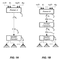
- FIG. 1A A prior-art process is shown in FIG. 1A , whereby a panning function is used inside Panner A [1], to produce the N p -channel Original Soundfield Signal [5], Y ( t ), which is subsequently decoded to a set of N S Speaker Signals, by Speaker Decoder [4] (an [ N S ⁇ N p ] matrix).
- a Soundfield Format may be used in situations where the playback speaker arrangement is unknown.
- the quality of the final listening experience will depend on both (a) the information-carrying capacity of the Soundfield Format and (b) the quantity and arrangement of speakers used in the playback environment.
- N p the number of channels in the Original Soundfield Signal [5].
- Panner A [1] will make use of a particular family of panning functions known as B-Format (also referred to in the literature as Spherical Harmonic, Ambisonic, or Higher Order Ambisonic, panning rules), and this disclosure is initially concerned with spatial formats that are based on B-Format panning rules.
- B-Format also referred to in the literature as Spherical Harmonic, Ambisonic, or Higher Order Ambisonic, panning rules
- FIG. 1B shows an alternative panner, Panner B [2], configured to produce Input Soundfield Signal [6], an N r -channel Spatial Format x ( t ), which is then processed to create an N p -channel Output Soundfield Signal [7], y ( t ), by the Format Converter [3], where N p > N r .
- This disclosure describes methods for implementing the Format Converter [3].
- this disclosure provides methods that may be used to construct the Linear Time Invariant (LTI) filters used in the Format Converter [3], in order to provide an N r -input, N p -output LTI transfer function for our Format Converter [3], so that the listening experience provided by the system of FIG. 1B is perceptually as close as possible to the listening experience of the system of FIG. 1A .
- LTI Linear Time Invariant
- Panner A [1] of FIG 1A is configured to produce a 4 th -order horizontal B-Format soundfield, according to the following panner equations (note that the terminology BF 4 h is used to indicate Horizontal 4 th - order B-Format ):
- variable ⁇ represents an azimuth angle
- N p 9
- P BF 4 h ( ⁇ ) represents a [9 ⁇ 1] column vector (and hence, the signal Y ( t ) will consist of 9 audio channels).
- N r 3 and P BF 1 h ( ⁇ ) represents a [3 ⁇ 1] column vector (and hence, the signal X ( t ) of FIG 1B will consist of 3 audio channels).
- our goal is to create the 9-channel Output Soundfield Signal [7] of FIG 1B , Y ( t ), that is derived by an LTI process from X( t ), suitable for decoding to any speaker array, so that an optimized listening experience is attained.
- the Format Converter [3] receives the N r -channel Input Soundfield Signal [6] as input and outputs the N p -channel Output Soundfield Signal [7].
- the Format Converter [3] will generally not receive information regarding the final speaker arrangement in the listeners playback environment. We can safely ignore the speaker arrangement if we choose to assume that the listener has a large enough number of speakers (this is the aforementioned assumption, N S ⁇ N p ), although the methods described in this disclosure will still produce an appropriate listening experience for a listener whose playback environment has fewer speakers.
- DecodeMatrix If we focus our attention to one speaker, we can ignore the other speakers in the array, and look at one row of DecodeMatrix. We will call this the DecodeRow Vector , Dec N ( ⁇ s ), indicating that this row of DecodeMatrix is intended to decode the N -channel Soundfield Signal to a speaker located at angle ⁇ s .
- Dec 3 ( ⁇ s ) is shown here, to allow us to examine the hypothetical scenario whereby a 3-channel BF 1 h signal is decoded to the speakers.
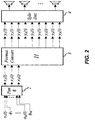
- Dec 9 ( ⁇ s ) is used in some implementations of the system shown in FIG. 2 .
- P 3 ( ⁇ ) represents a [3 ⁇ 1] vector of gain values that pans the input audio object, at location ⁇ , into the BF 1 h format.
- H represents a [9 ⁇ 3] matrix that performs the Format Conversion from the BF 1 h Format to the BF 4 h Format.
- Dec 9 ( ⁇ s ) represents a [1 ⁇ 9] row vector that decoded the BF 4 h signal to a loudspeaker located a position ⁇ s in the listening environment.
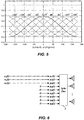
- the solid line in FIG. 3 shows the gain, gain 3 ( ⁇ , ⁇ s ), when an object is panned in the BH 1 h 3-channel Soundfield Format, and then decoded to a speaker array by the Dec 3 (0) Decode Row Vector.
- the gain curves shown in FIG. 3 can be re-plotted, to show all of the speaker gains. This allows us to see how the speakers interact with each other.
- FIG. 5 shows the result when the BH 1 h Soundfield Format is decoded to 9 speakers.
- Some implementations disclosed herein can reduce the correlation between speaker channels whilst preserving the same power distribution.
- H LS H LS ⁇ X t
- Equation 16 M p + represents the Moore-Penrose pseudoinverse, which is well known in the art.
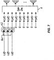
- FIG. 6 and FIG. 7 Whilst the Format Converts of Figures FIG. 6 and FIG. 7 will provide a somewhat-acceptable playback experience for the listener, they can produce a very large degree of correlation between neighboring speakers, as evidenced by the overlapping curves in FIG. 5 .
- a better alternative is to add more energy into the higher-order terms of the BF 4 h signals, using decorrelated versions of the BF 1 h input signals.
- Some implementations disclosed herein involve defining a method of synthesizing approximations of one or more higher-order components of Y ( t ) (e.g., y 4 ( t ), y 5 ( t ), y 6 ( t ), y 7 ( t ), y 8 ( t ) and y 9 ( t )) from one or more low resolution soundfield components of X ( t ) (e.g., x 1 ( t ), x 2 ( t ) and x 3 ( t )).
- decorrelators are merely examples.
- other methods of decorrelation such as other decorrelation methods that are well known to those of ordinary skill in the art, may be used in place of, or in addition to, the decorrelation methods described herein.
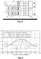
- decorrelators such as ⁇ 1 and ⁇ 2 of FIG. 8
- FIG. 8 A block diagram for implementing one such method is shown in FIG. 8 .
- Equations (27), x 1 (t), x 2 (t) and x 3 (t) represent inputs to the First Decorrelator [8].
- One very desirable result involves a mixture of these three gain curves, with the mixing coefficients ( g 0 , g 1 and g 2 ) determined by listener preference tests.
- the second decorrelator may be replaced by:
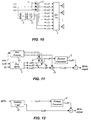
- Equation 29 represents a Hilbert transform, which effectively means that our second decorrelation process is identical to our first decorrelation process, with an additional phase shift of 90° (the Hilbert transform). If we substitute this expression for ⁇ 2 into the Second Decorrelator [10] in FIG. 8 , we arrive at the new diagram in FIG. 10 .
- the first decorrelation process involves a first decorrelation function and the second decorrelation process involves a second decorrelation function.
- the second decorrelation function may equal the first decorrelation function with a phase shift of approximately 90 degrees or approximately -90 degrees.
- an angle of approximately 90 degrees may be an angle in the range of 89 degrees to 91 degrees, an angle in the range of 88 degrees to 92 degrees, an angle in the range of 87 degrees to 93 degrees, an angle in the range of 86 degrees to 94 degrees, an angle in the range of 85 degrees to 95 degrees, an angle in the range of 84 degrees to 96 degrees, an angle in the range of 83 degrees to 97 degrees, an angle in the range of 82 degrees to 98 degrees, an angle in the range of 81 degrees to 99 degrees, an angle in the range of 80 degrees to 100 degrees, etc.
- an angle of approximately - 90 degrees may be an angle in the range of -89 degrees to -91 degrees, an angle in the range of -88 degrees to -92 degrees, an angle in the range of -87 degrees to -93 degrees, an angle in the range of -86 degrees to -94 degrees, an angle in the range of -85 degrees to -95 degrees, an angle in the range of -84 degrees to -96 degrees, an angle in the range of -83 degrees to - 97 degrees, an angle in the range of -82 degrees to -98 degrees, an angle in the range of -81 degrees to -99 degrees, an angle in the range of -80 degrees to -100 degrees, etc.
- the phase shift may vary as a function of frequency. According to some such implementations, the phase shift may be approximately 90 degrees over only some frequency range of interest. In some such examples, the frequency range of interest may include a range from 300Hz to 2kHz. Other examples may apply other phase shifts and/or may apply a phase shift of approximately 90 degrees over other frequency ranges.
- the first modulation process involves a first modulation function and the second modulation process involves a second modulation function, the second modulation function being the first modulation function with a phase shift of approximately 90 degrees or approximately -90 degrees.
- the second modulation function is the first modulation function with a phase shift of approximately 90 degrees or approximately -90 degrees.
- the Q matrices may also be reduced to a lesser number of rows, in order to reduce the number of channels in the output format, resulting in the following Q matrices:
- soundfield input formats may also be processed according to the methods disclosed herein, including:
- modulation methods as defined herein are applicable to a wide range of Soundfield Formats.
- FIG. 11 shows a system suitable for rendering an audio object, wherein a Format Converter [3] is used to create a 9-channel BF 4 h signal, y 1 ( t ) ⁇ y 9 ( t ), from a lower-resolution BF 1 h signal, x 1 ( t ) ⁇ x 3 ( t ).
- a Format Converter [3] is used to create a 9-channel BF 4 h signal, y 1 ( t ) ⁇ y 9 ( t ), from a lower-resolution BF 1 h signal, x 1 ( t ) ⁇ x 3 ( t ).
- an audio object, o 1 ( t ) is panned to form an intermediate 9-channel BF 4 h signal, z 1 ( t ) ⁇ z 9 ( t ).
- This high-resolution signal is summed to the BF 4 h output, via Direct Gain Scaler [15], allowing the audio object, o 1 ( t ), to be represented in the BF 4 h output with high resolution (so it will appear to the listener as a compact object).
- the 0 th -order and 1 st -order components of the BF 4 h signals ( z 1 (t) and z 2 ( t ) ⁇ z 3 ( t ) respectively) are modified by Zeroth Order Gain Scaler [17] and First Order Gain Scaler [16], to form the 3-channel BF 1 h signal, x 1 ( t ) ⁇ x 3 ( t ).
- the values of the three gain parameters will vary as piecewise-linear functions, which may be based on the values defined here.
- the BF 1 h signal formed by scaling the zeroth- and first-order components of the BF 4 h signal is passed through a format converter (e.g., as the type described previously) in order to generate a format-converted BF 4 h signal.
- the direct and format-converted BF 4 h signals are then combined in order to form the size-adjusted BF 4 h output signal.
- the perceived size of the object panned to the BF 4 h output signal may be varied between a point source and a very large source (e.g., encompassing the entire room).
- An upmixer such as that shown in FIG. 12 operates by use of a Steering Logic Process [18], which takes, as input, a low resolution soundfield signal (for example, BF 1 h ).
- the Steering Logic Process [18] may identify components of the input soundfield signal that are to be steered as accurately as possible (and processing those components to form the high-resolution output signal z 1 ( t ) ⁇ z 9 ( t )).
- the Steering Logic Process [18] will emit a residual signal, x 1 ( t ) ⁇ x 3 ( t ) .
- This residual signal contains the audio components that are not steered to form the high-resolution signal, z 1 ( t ) ⁇ z 9 ( t ).
- this residual signal, x 1 ( t ) ⁇ ⁇ ⁇ x 3 ( t ), is processed by the Format Converter [3], to provide a higher-resolution version of the residual signal, suitable for combining with the steered signal, z 1 ( t ) ⁇ z 9 ( t ).
- FIG. 12 shows an example of combining the N p audio channels of steered audio data with the N p audio channels of the output audio signal of the format converter in order to produce an upmixed BF 4 h output signal.
- the computational complexity of generating the BF 1 h residual signal and applying the format converter to that signal to generate the converted BF 4 h residual signal is lower than the computational complexity of directly upmixing the residual signals to BF 4 h format using the steering logic, a reduced computational complexity upmixing is achieved.
- the residual signals are perceptually less relevant than the dominant signals, the resulting upmixed BF 4 h output signal generated using an upmixer as shown in Fig. 12 will be perceptually similar to the BF 4 h output signal generated by, e.g., an upmixer which uses steering logic to directly generate both high accuracy dominant and residual BF 4 h output signals, but can be generated with reduced computational complexity.
- FIG. 13 is a block diagram that provides examples of components of an apparatus capable of implementing various methods described herein.
- the apparatus 1300 may, for example, be (or may be a portion of) an audio data processing system. In some examples, the apparatus 1300 may be implemented in a component of another device.
- the apparatus 1300 includes an interface system 1305 and a control system 1310.
- the control system 1310 may be capable of implementing some or all of the methods disclosed herein.
- the control system 1310 may, for example, include a general purpose single- or multi-chip processor, a digital signal processor (DSP), an application specific integrated circuit (ASIC), a field programmable gate array (FPGA) or other programmable logic device, discrete gate or transistor logic, and/or discrete hardware components.
- DSP digital signal processor
- ASIC application specific integrated circuit
- FPGA field programmable gate array
- the apparatus 1300 includes a memory system 1315.
- the memory system 1315 may include one or more suitable types of non-transitory storage media, such as flash memory, a hard drive, etc.
- the interface system 1305 may include a network interface, an interface between the control system and the memory system and/or an external device interface (such as a universal serial bus (USB) interface).
- USB universal serial bus
- the memory system 1315 is depicted as a separate element in FIG. 13
- the control system 1310 may include at least some memory, which may be regarded as a portion of the memory system.
- the memory system 1315 may be capable of providing some control system functionality.
- control system 1310 is capable of receiving audio data and other information via the interface system 1305.
- control system 1310 may include (or may implement), an audio processing apparatus.
- control system 1310 may be capable of performing at least some of the methods described herein according to software stored on one or more non-transitory media.
- the non-transitory media may include memory associated with the control system 1310, such as random access memory (RAM) and/or read-only memory (ROM).
- RAM random access memory
- ROM read-only memory
- the non-transitory media may include memory of the memory system 1315.
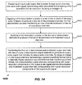
- FIG. 14 is a flow diagram that shows example blocks of a format conversion process according to some implementations.
- the blocks of FIG. 14 may, for example, be performed by the control system 1310 of FIG. 13 or by a similar apparatus. Accordingly, some blocks of FIG. 14 are described below with reference to one or more elements of FIG. 13 . As with other methods disclosed herein, the method outlined in FIG. 14 may include more or fewer blocks than indicated. Moreover, the blocks of methods disclosed herein are not necessarily performed in the order indicated.
- block 1405 involves receiving an input audio signal that includes N r input audio channels.
- N r is an integer ⁇ 2.
- the input audio signal represents a first soundfield format having a first soundfield format resolution.
- the first soundfield format may be a 3-channel BF 1 h Soundfield Format, whereas in other examples the first soundfield format may be a BF1 (4-channel, 1st order Ambisonics, also known as WXYZ-format), a BF2 (9-channel, 2nd order Ambisonics) format, or another soundfield format.
- block 1410 involves applying a first decorrelation process to a set of two or more of the input audio channels to produce a first set of decorrelated channels.
- the first decorrelation process maintains an inter-channel correlation of the set of input audio channels.
- the first decorrelation process may, for example, correspond with one of the implementations of the decorrelator ⁇ 1 that are described above with reference to FIG. 8 and FIG. 10 .
- applying the first decorrelation process involves applying an identical decorrelation process to each of the N r input audio channels.
- block 1415 involves applying a first modulation process to the first set of decorrelated channels to produce a first set of decorrelated and modulated output channels.
- the first modulation process may, for example, correspond with one of the implementations of the First Modulator [9] that is described above with reference to FIG. 8 or with one of the implementations of the Modulator [13] that is described above with reference to FIG. 10 . Accordingly, the modulation process may involve applying a linear matrix to the first set of decorrelated channels.
- block 1420 involves combining the first set of decorrelated and modulated output channels with two or more undecorrelated output channels to produce an output audio signal that includes N p output audio channels.
- N p is an integer ⁇ 3.
- the output channels represent a second soundfield format that is a relatively higher-resolution soundfield format than the first soundfield format.
- the second soundfield format is a 9-channel BF 4 h Soundfield Format.
- the second soundfield format may be another soundfield format, such as a 7-channel BF 3 h format, a 5-channel BF 3 h format, a BF 2 soundfield format (9-channel 2 nd order Ambisonics), a BF 3 soundfield format (16-channel 3 rd order Ambisonics), or another soundfield format.
- the undecorrelated output channels correspond with lower-resolution components of the output audio signal and the decorrelated and modulated output channels correspond with higher-resolution components of the output audio signal.
- the output channels y 1 (t)- y 3 (t) provide examples of the undecorrelated output channels.
- the undecorrelated output channels are produced by applying a least-squares format converter to the N r input audio channels.
- output channels y 4 (t)- y 9 (t) provide examples of decorrelated and modulated output channels produced by the first decorrelation process and the first modulation process.
- the first decorrelation process involves a first decorrelation function and the second decorrelation process involves a second decorrelation function, wherein the second decorrelation function is the first decorrelation function with a phase shift of approximately 90 degrees or approximately -90 degrees.
- the first modulation process involves a first modulation function and the second modulation process involves a second modulation function, wherein the second modulation function is the first modulation function with a phase shift of approximately 90 degrees or approximately -90 degrees.
- the decorrelation, modulation and combining produce the output audio signal such that, when the output audio signal is decoded and provided to an array of speakers, the spatial distribution of the energy in the array of speakers is substantially the same as the spatial distribution of the energy that would result from the input audio signal being decoded to the array of speakers via a least-squares decoder.
- the correlation between adjacent loudspeakers in the array of speakers is substantially different from the correlation that would result from the input audio signal being decoded to the array of speakers via a least-squares decoder.
- Some implementations may involve implementing a format converter for rendering objects with size. Some such implementations may involve receiving an indication of audio object size, determining that the audio object size is greater than or equal to a threshold size and applying a zero gain value to the set of two or more input audio channels.
- Some examples may involve implementing a format converter in an upmixer. Some such implementations may involve receiving output from an audio steering logic process, the output including N p audio channels of steered audio data in which a gain of one or more channels has been altered, based on a current dominant sound direction. Some examples may involve combining the N p audio channels of steered audio data with the N p audio channels of the output audio signal.
Landscapes
- Engineering & Computer Science (AREA)
- Physics & Mathematics (AREA)
- Signal Processing (AREA)
- Acoustics & Sound (AREA)
- Multimedia (AREA)
- Mathematical Physics (AREA)
- Computational Linguistics (AREA)
- Health & Medical Sciences (AREA)
- Audiology, Speech & Language Pathology (AREA)
- Human Computer Interaction (AREA)
- Stereophonic System (AREA)
Priority Applications (2)
| Application Number | Priority Date | Filing Date | Title |
|---|---|---|---|
| EP19172220.6A EP3611727B1 (en) | 2015-03-03 | 2016-03-02 | Enhancement of spatial audio signals by modulated decorrelation |
| EP22170424.0A EP4123643B1 (en) | 2015-03-03 | 2016-03-02 | Enhancement of spatial audio signals by modulated decorrelation |
Applications Claiming Priority (3)
| Application Number | Priority Date | Filing Date | Title |
|---|---|---|---|
| US201562127613P | 2015-03-03 | 2015-03-03 | |
| US201662298905P | 2016-02-23 | 2016-02-23 | |
| PCT/US2016/020380 WO2016141023A1 (en) | 2015-03-03 | 2016-03-02 | Enhancement of spatial audio signals by modulated decorrelation |
Related Child Applications (2)
| Application Number | Title | Priority Date | Filing Date |
|---|---|---|---|
| EP22170424.0A Division EP4123643B1 (en) | 2015-03-03 | 2016-03-02 | Enhancement of spatial audio signals by modulated decorrelation |
| EP19172220.6A Division EP3611727B1 (en) | 2015-03-03 | 2016-03-02 | Enhancement of spatial audio signals by modulated decorrelation |
Publications (2)
| Publication Number | Publication Date |
|---|---|
| EP3266021A1 EP3266021A1 (en) | 2018-01-10 |
| EP3266021B1 true EP3266021B1 (en) | 2019-05-08 |
Family
ID=55854783
Family Applications (3)
| Application Number | Title | Priority Date | Filing Date |
|---|---|---|---|
| EP16718934.9A Active EP3266021B1 (en) | 2015-03-03 | 2016-03-02 | Enhancement of spatial audio signals by modulated decorrelation |
| EP19172220.6A Active EP3611727B1 (en) | 2015-03-03 | 2016-03-02 | Enhancement of spatial audio signals by modulated decorrelation |
| EP22170424.0A Active EP4123643B1 (en) | 2015-03-03 | 2016-03-02 | Enhancement of spatial audio signals by modulated decorrelation |
Family Applications After (2)
| Application Number | Title | Priority Date | Filing Date |
|---|---|---|---|
| EP19172220.6A Active EP3611727B1 (en) | 2015-03-03 | 2016-03-02 | Enhancement of spatial audio signals by modulated decorrelation |
| EP22170424.0A Active EP4123643B1 (en) | 2015-03-03 | 2016-03-02 | Enhancement of spatial audio signals by modulated decorrelation |
Country Status (6)
| Country | Link |
|---|---|
| US (5) | US10210872B2 (enExample) |
| EP (3) | EP3266021B1 (enExample) |
| JP (3) | JP6576458B2 (enExample) |
| CN (2) | CN112002337B (enExample) |
| ES (1) | ES2922373T3 (enExample) |
| WO (1) | WO2016141023A1 (enExample) |
Families Citing this family (5)
| Publication number | Priority date | Publication date | Assignee | Title |
|---|---|---|---|---|
| JP6576458B2 (ja) | 2015-03-03 | 2019-09-18 | ドルビー ラボラトリーズ ライセンシング コーポレイション | 変調された脱相関による空間的オーディオ信号の向上 |
| US10334387B2 (en) | 2015-06-25 | 2019-06-25 | Dolby Laboratories Licensing Corporation | Audio panning transformation system and method |
| US10015618B1 (en) * | 2017-08-01 | 2018-07-03 | Google Llc | Incoherent idempotent ambisonics rendering |
| CN111819627B (zh) | 2018-07-02 | 2025-04-11 | 杜比实验室特许公司 | 用于对沉浸式音频信号进行编码及/或解码的方法及装置 |
| WO2021098957A1 (en) * | 2019-11-20 | 2021-05-27 | Fraunhofer-Gesellschaft zur Förderung der angewandten Forschung e.V. | Audio object renderer, methods for determining loudspeaker gains and computer program using panned object loudspeaker gains and spread object loudspeaker gains |
Family Cites Families (20)
| Publication number | Priority date | Publication date | Assignee | Title |
|---|---|---|---|---|
| JPH11275696A (ja) * | 1998-01-22 | 1999-10-08 | Sony Corp | ヘッドホン、ヘッドホンアダプタおよびヘッドホン装置 |
| CN100539737C (zh) * | 2001-03-27 | 2009-09-09 | 1...有限公司 | 产生声场的方法和装置 |
| US8363865B1 (en) | 2004-05-24 | 2013-01-29 | Heather Bottum | Multiple channel sound system using multi-speaker arrays |
| ES2333137T3 (es) * | 2004-07-14 | 2010-02-17 | Koninklijke Philips Electronics N.V. | Conversion de canal de audio. |
| DE102005010057A1 (de) * | 2005-03-04 | 2006-09-07 | Fraunhofer-Gesellschaft zur Förderung der angewandten Forschung e.V. | Vorrichtung und Verfahren zum Erzeugen eines codierten Stereo-Signals eines Audiostücks oder Audiodatenstroms |
| ES2433316T3 (es) * | 2005-07-19 | 2013-12-10 | Koninklijke Philips N.V. | Generación de señales de audio de multiples canales |
| EP1927265A2 (en) * | 2005-09-13 | 2008-06-04 | Koninklijke Philips Electronics N.V. | A method of and a device for generating 3d sound |
| US8515468B2 (en) | 2005-09-21 | 2013-08-20 | Buckyball Mobile Inc | Calculation of higher-order data from context data |
| US8073703B2 (en) * | 2005-10-07 | 2011-12-06 | Panasonic Corporation | Acoustic signal processing apparatus and acoustic signal processing method |
| WO2007118583A1 (en) * | 2006-04-13 | 2007-10-25 | Fraunhofer-Gesellschaft zur Förderung der angewandten Forschung e.V. | Audio signal decorrelator |
| US9015051B2 (en) * | 2007-03-21 | 2015-04-21 | Fraunhofer-Gesellschaft Zur Foerderung Der Angewandten Forschung E.V. | Reconstruction of audio channels with direction parameters indicating direction of origin |
| MX2011000372A (es) * | 2008-07-11 | 2011-05-19 | Fraunhofer Ges Forschung | Sintetizador de señales de audio y codificador de señales de audio. |
| TWI444989B (zh) * | 2010-01-22 | 2014-07-11 | Dolby Lab Licensing Corp | 針對改良多通道上混使用多通道解相關之技術 |
| EP2560161A1 (en) * | 2011-08-17 | 2013-02-20 | Fraunhofer-Gesellschaft zur Förderung der angewandten Forschung e.V. | Optimal mixing matrices and usage of decorrelators in spatial audio processing |
| CN103165136A (zh) * | 2011-12-15 | 2013-06-19 | 杜比实验室特许公司 | 音频处理方法及音频处理设备 |
| EP2830336A3 (en) * | 2013-07-22 | 2015-03-04 | Fraunhofer-Gesellschaft zur Förderung der angewandten Forschung e.V. | Renderer controlled spatial upmix |
| EP2830334A1 (en) * | 2013-07-22 | 2015-01-28 | Fraunhofer-Gesellschaft zur Förderung der angewandten Forschung e.V. | Multi-channel audio decoder, multi-channel audio encoder, methods, computer program and encoded audio representation using a decorrelation of rendered audio signals |
| CN110797037B (zh) * | 2013-07-31 | 2024-12-27 | 杜比实验室特许公司 | 用于处理音频数据的方法和装置、介质及设备 |
| EP2980789A1 (en) * | 2014-07-30 | 2016-02-03 | Fraunhofer-Gesellschaft zur Förderung der angewandten Forschung e.V. | Apparatus and method for enhancing an audio signal, sound enhancing system |
| JP6576458B2 (ja) | 2015-03-03 | 2019-09-18 | ドルビー ラボラトリーズ ライセンシング コーポレイション | 変調された脱相関による空間的オーディオ信号の向上 |
-
2016
- 2016-03-02 JP JP2017542860A patent/JP6576458B2/ja active Active
- 2016-03-02 CN CN202010914886.6A patent/CN112002337B/zh active Active
- 2016-03-02 CN CN201680011460.1A patent/CN107430861B/zh active Active
- 2016-03-02 WO PCT/US2016/020380 patent/WO2016141023A1/en not_active Ceased
- 2016-03-02 EP EP16718934.9A patent/EP3266021B1/en active Active
- 2016-03-02 ES ES19172220T patent/ES2922373T3/es active Active
- 2016-03-02 EP EP19172220.6A patent/EP3611727B1/en active Active
- 2016-03-02 EP EP22170424.0A patent/EP4123643B1/en active Active
- 2016-03-02 US US15/546,258 patent/US10210872B2/en active Active
-
2019
- 2019-02-14 US US16/276,397 patent/US10593338B2/en active Active
- 2019-08-20 JP JP2019150274A patent/JP6926159B2/ja active Active
-
2020
- 2020-03-11 US US16/816,189 patent/US11081119B2/en active Active
-
2021
- 2021-08-02 US US17/392,172 patent/US11562750B2/en active Active
- 2021-08-04 JP JP2021128119A patent/JP7321218B2/ja active Active
-
2023
- 2023-01-23 US US18/158,032 patent/US20230230600A1/en not_active Abandoned
Non-Patent Citations (1)
| Title |
|---|
| None * |
Also Published As
| Publication number | Publication date |
|---|---|
| EP3611727B1 (en) | 2022-05-04 |
| JP2021177668A (ja) | 2021-11-11 |
| ES2922373T3 (es) | 2022-09-14 |
| US20180018977A1 (en) | 2018-01-18 |
| EP4123643B1 (en) | 2024-06-19 |
| JP7321218B2 (ja) | 2023-08-04 |
| JP2020005278A (ja) | 2020-01-09 |
| EP3611727A1 (en) | 2020-02-19 |
| CN112002337A (zh) | 2020-11-27 |
| US20220028400A1 (en) | 2022-01-27 |
| US10210872B2 (en) | 2019-02-19 |
| JP6576458B2 (ja) | 2019-09-18 |
| US10593338B2 (en) | 2020-03-17 |
| US11081119B2 (en) | 2021-08-03 |
| US20190180760A1 (en) | 2019-06-13 |
| WO2016141023A1 (en) | 2016-09-09 |
| US20200273469A1 (en) | 2020-08-27 |
| CN112002337B (zh) | 2024-08-09 |
| EP3266021A1 (en) | 2018-01-10 |
| CN107430861A (zh) | 2017-12-01 |
| JP6926159B2 (ja) | 2021-08-25 |
| CN107430861B (zh) | 2020-10-16 |
| EP4123643A1 (en) | 2023-01-25 |
| US11562750B2 (en) | 2023-01-24 |
| US20230230600A1 (en) | 2023-07-20 |
| JP2018511213A (ja) | 2018-04-19 |
Similar Documents
| Publication | Publication Date | Title |
|---|---|---|
| US20230230600A1 (en) | Enhancement of spatial audio signals by modulated decorrelation | |
| AU2022291443B2 (en) | Method for and apparatus for decoding an ambisonics audio soundfield representation for audio playback using 2D setups | |
| US10231073B2 (en) | Ambisonic audio rendering with depth decoding | |
| AU2013292057B2 (en) | Method and device for rendering an audio soundfield representation for audio playback | |
| US8175280B2 (en) | Generation of spatial downmixes from parametric representations of multi channel signals | |
| KR102226071B1 (ko) | 다채널 오디오 신호의 바이노럴 렌더링 방법 및 장치 | |
| US11212631B2 (en) | Method for generating binaural signals from stereo signals using upmixing binauralization, and apparatus therefor | |
| EP3625974B1 (en) | Methods, systems and apparatus for conversion of spatial audio format(s) to speaker signals | |
| HK40016792B (en) | Enhancement of spatial audio signals by modulated decorrelation | |
| HK40016792A (en) | Enhancement of spatial audio signals by modulated decorrelation |
Legal Events
| Date | Code | Title | Description |
|---|---|---|---|
| STAA | Information on the status of an ep patent application or granted ep patent |
Free format text: STATUS: THE INTERNATIONAL PUBLICATION HAS BEEN MADE |
|
| PUAI | Public reference made under article 153(3) epc to a published international application that has entered the european phase |
Free format text: ORIGINAL CODE: 0009012 |
|
| STAA | Information on the status of an ep patent application or granted ep patent |
Free format text: STATUS: REQUEST FOR EXAMINATION WAS MADE |
|
| 17P | Request for examination filed |
Effective date: 20171004 |
|
| AK | Designated contracting states |
Kind code of ref document: A1 Designated state(s): AL AT BE BG CH CY CZ DE DK EE ES FI FR GB GR HR HU IE IS IT LI LT LU LV MC MK MT NL NO PL PT RO RS SE SI SK SM TR |
|
| AX | Request for extension of the european patent |
Extension state: BA ME |
|
| DAV | Request for validation of the european patent (deleted) | ||
| DAX | Request for extension of the european patent (deleted) | ||
| GRAP | Despatch of communication of intention to grant a patent |
Free format text: ORIGINAL CODE: EPIDOSNIGR1 |
|
| STAA | Information on the status of an ep patent application or granted ep patent |
Free format text: STATUS: GRANT OF PATENT IS INTENDED |
|
| INTG | Intention to grant announced |
Effective date: 20181012 |
|
| RIN1 | Information on inventor provided before grant (corrected) |
Inventor name: MCGRATH, DAVID S. |
|
| GRAS | Grant fee paid |
Free format text: ORIGINAL CODE: EPIDOSNIGR3 |
|
| GRAA | (expected) grant |
Free format text: ORIGINAL CODE: 0009210 |
|
| STAA | Information on the status of an ep patent application or granted ep patent |
Free format text: STATUS: THE PATENT HAS BEEN GRANTED |
|
| AK | Designated contracting states |
Kind code of ref document: B1 Designated state(s): AL AT BE BG CH CY CZ DE DK EE ES FI FR GB GR HR HU IE IS IT LI LT LU LV MC MK MT NL NO PL PT RO RS SE SI SK SM TR |
|
| REG | Reference to a national code |
Ref country code: GB Ref legal event code: FG4D |
|
| REG | Reference to a national code |
Ref country code: CH Ref legal event code: EP Ref country code: AT Ref legal event code: REF Ref document number: 1131461 Country of ref document: AT Kind code of ref document: T Effective date: 20190515 |
|
| REG | Reference to a national code |
Ref country code: DE Ref legal event code: R096 Ref document number: 602016013661 Country of ref document: DE |
|
| REG | Reference to a national code |
Ref country code: IE Ref legal event code: FG4D |
|
| REG | Reference to a national code |
Ref country code: NL Ref legal event code: MP Effective date: 20190508 |
|
| REG | Reference to a national code |
Ref country code: LT Ref legal event code: MG4D |
|
| PG25 | Lapsed in a contracting state [announced via postgrant information from national office to epo] |
Ref country code: NL Free format text: LAPSE BECAUSE OF FAILURE TO SUBMIT A TRANSLATION OF THE DESCRIPTION OR TO PAY THE FEE WITHIN THE PRESCRIBED TIME-LIMIT Effective date: 20190508 Ref country code: HR Free format text: LAPSE BECAUSE OF FAILURE TO SUBMIT A TRANSLATION OF THE DESCRIPTION OR TO PAY THE FEE WITHIN THE PRESCRIBED TIME-LIMIT Effective date: 20190508 Ref country code: LT Free format text: LAPSE BECAUSE OF FAILURE TO SUBMIT A TRANSLATION OF THE DESCRIPTION OR TO PAY THE FEE WITHIN THE PRESCRIBED TIME-LIMIT Effective date: 20190508 Ref country code: AL Free format text: LAPSE BECAUSE OF FAILURE TO SUBMIT A TRANSLATION OF THE DESCRIPTION OR TO PAY THE FEE WITHIN THE PRESCRIBED TIME-LIMIT Effective date: 20190508 Ref country code: FI Free format text: LAPSE BECAUSE OF FAILURE TO SUBMIT A TRANSLATION OF THE DESCRIPTION OR TO PAY THE FEE WITHIN THE PRESCRIBED TIME-LIMIT Effective date: 20190508 Ref country code: NO Free format text: LAPSE BECAUSE OF FAILURE TO SUBMIT A TRANSLATION OF THE DESCRIPTION OR TO PAY THE FEE WITHIN THE PRESCRIBED TIME-LIMIT Effective date: 20190808 Ref country code: PT Free format text: LAPSE BECAUSE OF FAILURE TO SUBMIT A TRANSLATION OF THE DESCRIPTION OR TO PAY THE FEE WITHIN THE PRESCRIBED TIME-LIMIT Effective date: 20190908 Ref country code: SE Free format text: LAPSE BECAUSE OF FAILURE TO SUBMIT A TRANSLATION OF THE DESCRIPTION OR TO PAY THE FEE WITHIN THE PRESCRIBED TIME-LIMIT Effective date: 20190508 Ref country code: ES Free format text: LAPSE BECAUSE OF FAILURE TO SUBMIT A TRANSLATION OF THE DESCRIPTION OR TO PAY THE FEE WITHIN THE PRESCRIBED TIME-LIMIT Effective date: 20190508 |
|
| PG25 | Lapsed in a contracting state [announced via postgrant information from national office to epo] |
Ref country code: GR Free format text: LAPSE BECAUSE OF FAILURE TO SUBMIT A TRANSLATION OF THE DESCRIPTION OR TO PAY THE FEE WITHIN THE PRESCRIBED TIME-LIMIT Effective date: 20190809 Ref country code: RS Free format text: LAPSE BECAUSE OF FAILURE TO SUBMIT A TRANSLATION OF THE DESCRIPTION OR TO PAY THE FEE WITHIN THE PRESCRIBED TIME-LIMIT Effective date: 20190508 Ref country code: BG Free format text: LAPSE BECAUSE OF FAILURE TO SUBMIT A TRANSLATION OF THE DESCRIPTION OR TO PAY THE FEE WITHIN THE PRESCRIBED TIME-LIMIT Effective date: 20190808 Ref country code: LV Free format text: LAPSE BECAUSE OF FAILURE TO SUBMIT A TRANSLATION OF THE DESCRIPTION OR TO PAY THE FEE WITHIN THE PRESCRIBED TIME-LIMIT Effective date: 20190508 |
|
| REG | Reference to a national code |
Ref country code: AT Ref legal event code: MK05 Ref document number: 1131461 Country of ref document: AT Kind code of ref document: T Effective date: 20190508 |
|
| PG25 | Lapsed in a contracting state [announced via postgrant information from national office to epo] |
Ref country code: AT Free format text: LAPSE BECAUSE OF FAILURE TO SUBMIT A TRANSLATION OF THE DESCRIPTION OR TO PAY THE FEE WITHIN THE PRESCRIBED TIME-LIMIT Effective date: 20190508 Ref country code: EE Free format text: LAPSE BECAUSE OF FAILURE TO SUBMIT A TRANSLATION OF THE DESCRIPTION OR TO PAY THE FEE WITHIN THE PRESCRIBED TIME-LIMIT Effective date: 20190508 Ref country code: DK Free format text: LAPSE BECAUSE OF FAILURE TO SUBMIT A TRANSLATION OF THE DESCRIPTION OR TO PAY THE FEE WITHIN THE PRESCRIBED TIME-LIMIT Effective date: 20190508 Ref country code: CZ Free format text: LAPSE BECAUSE OF FAILURE TO SUBMIT A TRANSLATION OF THE DESCRIPTION OR TO PAY THE FEE WITHIN THE PRESCRIBED TIME-LIMIT Effective date: 20190508 Ref country code: RO Free format text: LAPSE BECAUSE OF FAILURE TO SUBMIT A TRANSLATION OF THE DESCRIPTION OR TO PAY THE FEE WITHIN THE PRESCRIBED TIME-LIMIT Effective date: 20190508 Ref country code: SK Free format text: LAPSE BECAUSE OF FAILURE TO SUBMIT A TRANSLATION OF THE DESCRIPTION OR TO PAY THE FEE WITHIN THE PRESCRIBED TIME-LIMIT Effective date: 20190508 |
|
| REG | Reference to a national code |
Ref country code: DE Ref legal event code: R097 Ref document number: 602016013661 Country of ref document: DE |
|
| PG25 | Lapsed in a contracting state [announced via postgrant information from national office to epo] |
Ref country code: SM Free format text: LAPSE BECAUSE OF FAILURE TO SUBMIT A TRANSLATION OF THE DESCRIPTION OR TO PAY THE FEE WITHIN THE PRESCRIBED TIME-LIMIT Effective date: 20190508 Ref country code: IT Free format text: LAPSE BECAUSE OF FAILURE TO SUBMIT A TRANSLATION OF THE DESCRIPTION OR TO PAY THE FEE WITHIN THE PRESCRIBED TIME-LIMIT Effective date: 20190508 |
|
| PLBE | No opposition filed within time limit |
Free format text: ORIGINAL CODE: 0009261 |
|
| STAA | Information on the status of an ep patent application or granted ep patent |
Free format text: STATUS: NO OPPOSITION FILED WITHIN TIME LIMIT |
|
| PG25 | Lapsed in a contracting state [announced via postgrant information from national office to epo] |
Ref country code: TR Free format text: LAPSE BECAUSE OF FAILURE TO SUBMIT A TRANSLATION OF THE DESCRIPTION OR TO PAY THE FEE WITHIN THE PRESCRIBED TIME-LIMIT Effective date: 20190508 |
|
| 26N | No opposition filed |
Effective date: 20200211 |
|
| PG25 | Lapsed in a contracting state [announced via postgrant information from national office to epo] |
Ref country code: PL Free format text: LAPSE BECAUSE OF FAILURE TO SUBMIT A TRANSLATION OF THE DESCRIPTION OR TO PAY THE FEE WITHIN THE PRESCRIBED TIME-LIMIT Effective date: 20190508 |
|
| PG25 | Lapsed in a contracting state [announced via postgrant information from national office to epo] |
Ref country code: SI Free format text: LAPSE BECAUSE OF FAILURE TO SUBMIT A TRANSLATION OF THE DESCRIPTION OR TO PAY THE FEE WITHIN THE PRESCRIBED TIME-LIMIT Effective date: 20190508 |
|
| PG25 | Lapsed in a contracting state [announced via postgrant information from national office to epo] |
Ref country code: MC Free format text: LAPSE BECAUSE OF FAILURE TO SUBMIT A TRANSLATION OF THE DESCRIPTION OR TO PAY THE FEE WITHIN THE PRESCRIBED TIME-LIMIT Effective date: 20190508 |
|
| REG | Reference to a national code |
Ref country code: CH Ref legal event code: PL |
|
| REG | Reference to a national code |
Ref country code: BE Ref legal event code: MM Effective date: 20200331 |
|
| PG25 | Lapsed in a contracting state [announced via postgrant information from national office to epo] |
Ref country code: LU Free format text: LAPSE BECAUSE OF NON-PAYMENT OF DUE FEES Effective date: 20200302 |
|
| PG25 | Lapsed in a contracting state [announced via postgrant information from national office to epo] |
Ref country code: IE Free format text: LAPSE BECAUSE OF NON-PAYMENT OF DUE FEES Effective date: 20200302 Ref country code: CH Free format text: LAPSE BECAUSE OF NON-PAYMENT OF DUE FEES Effective date: 20200331 Ref country code: LI Free format text: LAPSE BECAUSE OF NON-PAYMENT OF DUE FEES Effective date: 20200331 |
|
| PG25 | Lapsed in a contracting state [announced via postgrant information from national office to epo] |
Ref country code: BE Free format text: LAPSE BECAUSE OF NON-PAYMENT OF DUE FEES Effective date: 20200331 |
|
| PG25 | Lapsed in a contracting state [announced via postgrant information from national office to epo] |
Ref country code: MT Free format text: LAPSE BECAUSE OF FAILURE TO SUBMIT A TRANSLATION OF THE DESCRIPTION OR TO PAY THE FEE WITHIN THE PRESCRIBED TIME-LIMIT Effective date: 20190508 Ref country code: CY Free format text: LAPSE BECAUSE OF FAILURE TO SUBMIT A TRANSLATION OF THE DESCRIPTION OR TO PAY THE FEE WITHIN THE PRESCRIBED TIME-LIMIT Effective date: 20190508 |
|
| PG25 | Lapsed in a contracting state [announced via postgrant information from national office to epo] |
Ref country code: MK Free format text: LAPSE BECAUSE OF FAILURE TO SUBMIT A TRANSLATION OF THE DESCRIPTION OR TO PAY THE FEE WITHIN THE PRESCRIBED TIME-LIMIT Effective date: 20190508 Ref country code: IS Free format text: LAPSE BECAUSE OF FAILURE TO SUBMIT A TRANSLATION OF THE DESCRIPTION OR TO PAY THE FEE WITHIN THE PRESCRIBED TIME-LIMIT Effective date: 20190908 |
|
| P01 | Opt-out of the competence of the unified patent court (upc) registered |
Effective date: 20230513 |
|
| PGFP | Annual fee paid to national office [announced via postgrant information from national office to epo] |
Ref country code: DE Payment date: 20250218 Year of fee payment: 10 |
|
| PGFP | Annual fee paid to national office [announced via postgrant information from national office to epo] |
Ref country code: FR Payment date: 20250218 Year of fee payment: 10 |
|
| PGFP | Annual fee paid to national office [announced via postgrant information from national office to epo] |
Ref country code: GB Payment date: 20250221 Year of fee payment: 10 |