EP3265656B1 - Mix box - Google Patents
Mix box Download PDFInfo
- Publication number
- EP3265656B1 EP3265656B1 EP16709740.1A EP16709740A EP3265656B1 EP 3265656 B1 EP3265656 B1 EP 3265656B1 EP 16709740 A EP16709740 A EP 16709740A EP 3265656 B1 EP3265656 B1 EP 3265656B1
- Authority
- EP
- European Patent Office
- Prior art keywords
- housing
- flow
- tube
- mixing box
- outlet tube
- Prior art date
- Legal status (The legal status is an assumption and is not a legal conclusion. Google has not performed a legal analysis and makes no representation as to the accuracy of the status listed.)
- Revoked
Links
Images


Classifications
-
- F—MECHANICAL ENGINEERING; LIGHTING; HEATING; WEAPONS; BLASTING
- F01—MACHINES OR ENGINES IN GENERAL; ENGINE PLANTS IN GENERAL; STEAM ENGINES
- F01N—GAS-FLOW SILENCERS OR EXHAUST APPARATUS FOR MACHINES OR ENGINES IN GENERAL; GAS-FLOW SILENCERS OR EXHAUST APPARATUS FOR INTERNAL-COMBUSTION ENGINES
- F01N3/00—Exhaust or silencing apparatus having means for purifying, rendering innocuous, or otherwise treating exhaust
- F01N3/08—Exhaust or silencing apparatus having means for purifying, rendering innocuous, or otherwise treating exhaust for rendering innocuous
- F01N3/10—Exhaust or silencing apparatus having means for purifying, rendering innocuous, or otherwise treating exhaust for rendering innocuous by thermal or catalytic conversion of noxious components of exhaust
- F01N3/24—Exhaust or silencing apparatus having means for purifying, rendering innocuous, or otherwise treating exhaust for rendering innocuous by thermal or catalytic conversion of noxious components of exhaust characterised by constructional aspects of converting apparatus
- F01N3/28—Construction of catalytic reactors
- F01N3/2892—Exhaust flow directors or the like, e.g. upstream of catalytic device
-
- B—PERFORMING OPERATIONS; TRANSPORTING
- B01—PHYSICAL OR CHEMICAL PROCESSES OR APPARATUS IN GENERAL
- B01F—MIXING, e.g. DISSOLVING, EMULSIFYING OR DISPERSING
- B01F23/00—Mixing according to the phases to be mixed, e.g. dispersing or emulsifying
- B01F23/20—Mixing gases with liquids
- B01F23/21—Mixing gases with liquids by introducing liquids into gaseous media
- B01F23/213—Mixing gases with liquids by introducing liquids into gaseous media by spraying or atomising of the liquids
- B01F23/2132—Mixing gases with liquids by introducing liquids into gaseous media by spraying or atomising of the liquids using nozzles
-
- B—PERFORMING OPERATIONS; TRANSPORTING
- B01—PHYSICAL OR CHEMICAL PROCESSES OR APPARATUS IN GENERAL
- B01F—MIXING, e.g. DISSOLVING, EMULSIFYING OR DISPERSING
- B01F25/00—Flow mixers; Mixers for falling materials, e.g. solid particles
- B01F25/10—Mixing by creating a vortex flow, e.g. by tangential introduction of flow components
-
- B—PERFORMING OPERATIONS; TRANSPORTING
- B01—PHYSICAL OR CHEMICAL PROCESSES OR APPARATUS IN GENERAL
- B01F—MIXING, e.g. DISSOLVING, EMULSIFYING OR DISPERSING
- B01F25/00—Flow mixers; Mixers for falling materials, e.g. solid particles
- B01F25/30—Injector mixers
- B01F25/31—Injector mixers in conduits or tubes through which the main component flows
- B01F25/313—Injector mixers in conduits or tubes through which the main component flows wherein additional components are introduced in the centre of the conduit
- B01F25/3131—Injector mixers in conduits or tubes through which the main component flows wherein additional components are introduced in the centre of the conduit with additional mixing means other than injector mixers, e.g. screens, baffles or rotating elements
-
- F—MECHANICAL ENGINEERING; LIGHTING; HEATING; WEAPONS; BLASTING
- F01—MACHINES OR ENGINES IN GENERAL; ENGINE PLANTS IN GENERAL; STEAM ENGINES
- F01N—GAS-FLOW SILENCERS OR EXHAUST APPARATUS FOR MACHINES OR ENGINES IN GENERAL; GAS-FLOW SILENCERS OR EXHAUST APPARATUS FOR INTERNAL-COMBUSTION ENGINES
- F01N13/00—Exhaust or silencing apparatus characterised by constructional features
- F01N13/18—Construction facilitating manufacture, assembly, or disassembly
- F01N13/1888—Construction facilitating manufacture, assembly, or disassembly the housing of the assembly consisting of two or more parts, e.g. two half-shells
-
- B—PERFORMING OPERATIONS; TRANSPORTING
- B01—PHYSICAL OR CHEMICAL PROCESSES OR APPARATUS IN GENERAL
- B01F—MIXING, e.g. DISSOLVING, EMULSIFYING OR DISPERSING
- B01F25/00—Flow mixers; Mixers for falling materials, e.g. solid particles
- B01F2025/93—Arrangements, nature or configuration of flow guiding elements
- B01F2025/931—Flow guiding elements surrounding feed openings, e.g. jet nozzles
-
- F—MECHANICAL ENGINEERING; LIGHTING; HEATING; WEAPONS; BLASTING
- F01—MACHINES OR ENGINES IN GENERAL; ENGINE PLANTS IN GENERAL; STEAM ENGINES
- F01N—GAS-FLOW SILENCERS OR EXHAUST APPARATUS FOR MACHINES OR ENGINES IN GENERAL; GAS-FLOW SILENCERS OR EXHAUST APPARATUS FOR INTERNAL-COMBUSTION ENGINES
- F01N2240/00—Combination or association of two or more different exhaust treating devices, or of at least one such device with an auxiliary device, not covered by indexing codes F01N2230/00 or F01N2250/00, one of the devices being
- F01N2240/20—Combination or association of two or more different exhaust treating devices, or of at least one such device with an auxiliary device, not covered by indexing codes F01N2230/00 or F01N2250/00, one of the devices being a flow director or deflector
-
- F—MECHANICAL ENGINEERING; LIGHTING; HEATING; WEAPONS; BLASTING
- F01—MACHINES OR ENGINES IN GENERAL; ENGINE PLANTS IN GENERAL; STEAM ENGINES
- F01N—GAS-FLOW SILENCERS OR EXHAUST APPARATUS FOR MACHINES OR ENGINES IN GENERAL; GAS-FLOW SILENCERS OR EXHAUST APPARATUS FOR INTERNAL-COMBUSTION ENGINES
- F01N2470/00—Structure or shape of exhaust gas passages, pipes or tubes
- F01N2470/02—Tubes being perforated
- F01N2470/04—Tubes being perforated characterised by shape, disposition or dimensions of apertures
-
- F—MECHANICAL ENGINEERING; LIGHTING; HEATING; WEAPONS; BLASTING
- F01—MACHINES OR ENGINES IN GENERAL; ENGINE PLANTS IN GENERAL; STEAM ENGINES
- F01N—GAS-FLOW SILENCERS OR EXHAUST APPARATUS FOR MACHINES OR ENGINES IN GENERAL; GAS-FLOW SILENCERS OR EXHAUST APPARATUS FOR INTERNAL-COMBUSTION ENGINES
- F01N2470/00—Structure or shape of exhaust gas passages, pipes or tubes
- F01N2470/18—Structure or shape of exhaust gas passages, pipes or tubes the axis of inlet or outlet tubes being other than the longitudinal axis of apparatus
-
- F—MECHANICAL ENGINEERING; LIGHTING; HEATING; WEAPONS; BLASTING
- F01—MACHINES OR ENGINES IN GENERAL; ENGINE PLANTS IN GENERAL; STEAM ENGINES
- F01N—GAS-FLOW SILENCERS OR EXHAUST APPARATUS FOR MACHINES OR ENGINES IN GENERAL; GAS-FLOW SILENCERS OR EXHAUST APPARATUS FOR INTERNAL-COMBUSTION ENGINES
- F01N2470/00—Structure or shape of exhaust gas passages, pipes or tubes
- F01N2470/20—Dimensional characteristics of tubes, e.g. length, diameter
-
- F—MECHANICAL ENGINEERING; LIGHTING; HEATING; WEAPONS; BLASTING
- F01—MACHINES OR ENGINES IN GENERAL; ENGINE PLANTS IN GENERAL; STEAM ENGINES
- F01N—GAS-FLOW SILENCERS OR EXHAUST APPARATUS FOR MACHINES OR ENGINES IN GENERAL; GAS-FLOW SILENCERS OR EXHAUST APPARATUS FOR INTERNAL-COMBUSTION ENGINES
- F01N2490/00—Structure, disposition or shape of gas-chambers
- F01N2490/18—Dimensional characteristics of gas chambers
-
- F—MECHANICAL ENGINEERING; LIGHTING; HEATING; WEAPONS; BLASTING
- F01—MACHINES OR ENGINES IN GENERAL; ENGINE PLANTS IN GENERAL; STEAM ENGINES
- F01N—GAS-FLOW SILENCERS OR EXHAUST APPARATUS FOR MACHINES OR ENGINES IN GENERAL; GAS-FLOW SILENCERS OR EXHAUST APPARATUS FOR INTERNAL-COMBUSTION ENGINES
- F01N2610/00—Adding substances to exhaust gases
- F01N2610/02—Adding substances to exhaust gases the substance being ammonia or urea
-
- F—MECHANICAL ENGINEERING; LIGHTING; HEATING; WEAPONS; BLASTING
- F01—MACHINES OR ENGINES IN GENERAL; ENGINE PLANTS IN GENERAL; STEAM ENGINES
- F01N—GAS-FLOW SILENCERS OR EXHAUST APPARATUS FOR MACHINES OR ENGINES IN GENERAL; GAS-FLOW SILENCERS OR EXHAUST APPARATUS FOR INTERNAL-COMBUSTION ENGINES
- F01N3/00—Exhaust or silencing apparatus having means for purifying, rendering innocuous, or otherwise treating exhaust
- F01N3/08—Exhaust or silencing apparatus having means for purifying, rendering innocuous, or otherwise treating exhaust for rendering innocuous
- F01N3/10—Exhaust or silencing apparatus having means for purifying, rendering innocuous, or otherwise treating exhaust for rendering innocuous by thermal or catalytic conversion of noxious components of exhaust
- F01N3/18—Exhaust or silencing apparatus having means for purifying, rendering innocuous, or otherwise treating exhaust for rendering innocuous by thermal or catalytic conversion of noxious components of exhaust characterised by methods of operation; Control
- F01N3/20—Exhaust or silencing apparatus having means for purifying, rendering innocuous, or otherwise treating exhaust for rendering innocuous by thermal or catalytic conversion of noxious components of exhaust characterised by methods of operation; Control specially adapted for catalytic conversion
- F01N3/206—Adding periodically or continuously substances to exhaust gases for promoting purification, e.g. catalytic material in liquid form, NOx reducing agents
- F01N3/2066—Selective catalytic reduction [SCR]
Definitions
- the invention relates to a device for mixing exhaust gases, thus a mix box for an exhaust system of an internal combustion engine for mixing additives into an exhaust gas flow with at least one inlet pipe having an E-pipe axis, with at least one outlet pipe having an A-pipe axis and with one a housing wall having a housing with an inside and an outside for receiving the end-closed inlet pipe and the outlet pipe, the housing limiting a volume V of the mix box from an environment, the inlet pipe having an inflow part arranged inside the housing with a diameter Dz and with a Has length Lz, which is provided with at least one inflow opening for the purpose of introducing the exhaust gas into the housing, the outlet pipe at the end having a metering device and an outflow part arranged inside the housing with a diameter Da and a length La, for the purpose Discharge of the exhaust gas from the housing is provided with at least one outflow opening, a flow zone S being provided between the inlet pipe and the outlet pipe, which is laterally delimited by two interfaces B1, B2, each
- the arrangement has an inlet pipe and an outlet pipe arranged parallel thereto, which are arranged in the housing.
- the outlet pipe is placed off-center within a helical section of the housing wall, so that a tapering inlet gap is formed.
- a mixing tube arrangement with a housing is made of WO 2014/167355 A1 known.
- the arrangement has an outlet pipe which is partially arranged in the housing.
- a mixing tube arrangement with housing is also already known.
- the arrangement also has an inlet pipe and an outlet pipe arranged parallel thereto, which are arranged in the housing.
- a mixing tube arrangement with housing is also known.
- the arrangement also has an inlet pipe and an outlet pipe arranged parallel thereto, which are arranged in a two-part housing.
- the mixing device has a housing with an inlet opening and a perforated inner tube.
- the housing has a spiral housing section, via which the incoming exhaust gas is guided to the inner tube.
- the invention is based on the object of designing and arranging a mixing tube arrangement in such a way that optimum mixing is achieved despite the simple construction.
- the object is achieved according to the invention in that at least a portion Sf of 70% of the flow zones S is free of flow guide elements over at least 30% to 50% of the length La, a flow guide element causing a flow deflection in a direction R radially to the A-pipe axis and the flow guide element has a wall side and a gas side, both of which are arranged within the volume V.
- the respective flow zone S between the inflow part and the outflow part lies in the section plane to be considered, which is usually at right angles to the A-pipe axis.
- the flow zone S ends at the height of the E-pipe axis and below at the height of the A-pipe axis.
- the flow zone S ends laterally at the two interfaces B1, B2.
- the sum of all flow zones S of the different sectional planes spans a flow volume Vs as part of the housing volume.
- Flow control elements are components within the volume V, which complement the inside of the housing wall and which have a not insignificant influence on the deflection of the exhaust gas flow in the circumferential direction U to the A-pipe axis and / or in a direction R radially to the A-pipe axis.
- Parts of the housing wall which limit the volume V of the mix box to the outside are not to be regarded as flow control elements in the sense of the invention. This also applies if these parts of the housing wall are arranged within the flow zone S.
- Flow guiding elements are characterized in that both their wall or outside facing the next housing wall and their gas or inside facing the main gas flow are arranged in volume V within the housing.
- the outflow part is the part of the outlet pipe which has the at least one outflow opening. There are usually several outflow openings Form provided a series, which are distributed over the circumference U. If the outlet pipe has an outflow part that is significantly shorter than the part of the outlet pipe located in the housing, then when assessing the proportion of the length La that is free of flow guiding elements, the sum of the lengths of the different rows of outflow openings has to be based on together form the length of the outflow part.
- the flow thread F can be selected as the starting point or as the bisector, so that the distances or ratios mentioned are provided within the corresponding sector.
- inflow openings and outflow openings can also be designed as flaps or formations which are directed inwards and / or outwards
- the diameter Dz, Da and the radius are given Ra is based on the mean diameter or the diameter of the original pipe wall without flaps or projections.
- a minimum size for the flow zone S would be achieved if part of the housing wall is designed as a flow guide element and / or if further flow guide elements are provided in the form of guide plates, with a direct flow connection between the inlet pipe and the outlet pipe with respect to at least one flow thread F in the direction a flow vector T is provided, the flow vector T connecting the E-tube axis and the A-tube axis.
- the above-mentioned measures achieve and support an essentially direct and axis-symmetrical or mirror-symmetrical flow against the outlet pipe.
- the outlet pipe sits opposite the inlet pipe symmetrically in the surrounding housing part.
- a significant part of the exhaust gas flow can thus flow directly from the inlet pipe or the inflow openings without a deflection through flow guide elements such as the housing wall or guide plates to the outlet pipe.
- a predominantly swirl and vortex-free flow forms within the housing, which is largely defined by the inflow openings.
- This exhaust gas flow can then enter the exhaust pipe.
- the shape of the flow within the outlet pipe is thus largely determined by the geometry of the outflow part or the outflow opening. This in turn ensures that the additive is mixed in optimally.
- the housing can advantageously have a cubic or cylindrical basic shape with a cylinder radius Z, at least 80% to 90% of the surface portions of the housing wall either being flat or having a radius of curvature K corresponding to the cylinder radius Z.
- Such a simply designed housing forms the basis for an unaffected exhaust gas flow within the housing between the inlet and the outlet pipe.
- the outflow part can be flowed around on its outside by 360 °.
- a distance from the housing wall of at least Da / 8 to Da / 4 is provided. This ensures the symmetry of the inflow into the outflow part of the outlet pipe.
- the diameters Dz, Da vary over the length Lz, La.
- this is irrelevant for the definition of the teaching according to the invention, hence the definition of the interfaces B1, B2 and the distances a12, a22, a13, a23, r1, r2, r3, r4, r5.
- the geometrical relationships in the respective cutting plane are considered.
- a metering device such as an injection nozzle
- the spray angle ⁇ is selected such that an intersection point X with the pipe wall lies within the mixing sector S2 after the washing sector S1.
- the outlet pipe penetrates the housing wall at two opposite positions.
- the arrangement of the end-side metering device on the one hand and the discharge of the exhaust gas on the side opposite the metering device on the other hand are thus possible.
- the outlet pipe in the area of one or more outflow openings each has a wing articulated at least on one side, which projects inwards or outwards in the radial direction.
- the wing is designed like a flap, it has a straight bending edge on. Starting from a rectangular basic shape, it can thus have three free sides, so that the exhaust gas can flow around the wing over at least 60% to 80% of its circumference via the free edge and enter the outflow opening.
- blades can also be provided which have a rounded connection to the tube wall, which is generally longer than a straight bending edge. In this case, the exhaust gas can only flow around the wing over a small part of its circumference via the free edge and enter the outflow opening.
- the degree of perforation decreases in the flow direction in the inlet pipe.
- the incoming volume flow thus increases in the direction of the metering device, which leads to improved mixing.
- an intermediate wall which is aligned parallel to a main flow direction H.
- the intermediate wall serves to stabilize the housing or to store the pipes. There is therefore no adverse influence on the exhaust gas flow within the housing between the inlet and outlet pipes.
- the partition wall only eliminates flow components with a directional component parallel to the E or A pipe axis. This in turn contributes to the formation of a calm flow between the two pipes.
- the inlet pipe has a frustoconical basic shape G1 and / or the outlet pipe has a frustoconical basic shape G2, the inlet pipe and the outlet pipe with respect to the basic shape G1, G2 in the same direction or in opposite directions are aligned. If the tubes are aligned in the same direction, the housing itself or the cross section of the housing can also be frustoconical.
- the housing is formed from a maximum of two or three housing parts and at least one connecting flange for both Has housing parts. This ensures a simple construction on the one hand and favorable installation conditions for the pipes on the other hand.
- Both housing parts can be made from the same shell blank. With the exception of special designs such as plug-in flanges, each housing part usually has its own flange, so that both flanges are connected to each other to couple the two housing parts.
- the housing has a first housing part with a first housing edge and at least one second housing part with a second housing edge, both housing parts being at least partially connected via the housing edge spanning a division level e, the housing edge with reference to a normal N of the division plane e is point-symmetrical or is axisymmetric with reference to a straight line G of the division plane e. While the axially symmetrical design of the housing edge or the flange allows a variation in the relative position of the two housing parts pivoted by 180 ° in two positions, the point-symmetrical design ensures at least one variation within at least four positions, that is to say in steps of 90 °.
- Sector S1 is preferably wing-free.
- a spray cone with a spray angle ⁇ is provided, the spray angle ⁇ being selected such that an intersection point X between the spray cone and the outlet pipe in the direction of flow downstream of the first sector S1 and / or within the second sector S2 is provided. This supports the rinsing effect. Precipitation of additive in the nozzle area is prevented.
- the shape of the respective housing edge ensures that the respective tube is received over a partial circumference of approximately 180 °, so that both opposing shapes as well as during passage ensure that the respective tube is supported and sealed over the circumference U.
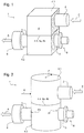
- a mix box 1 after Figure 1 is formed from two housing parts 4.1, 4.2, each with a housing edge 4a, 4b, which are coupled to one another via a connecting flange 4.4.
- An inlet pipe 2 with an inlet E for exhaust gas is arranged inside the first housing part 4.1, while an outlet pipe 3 with an outlet A is placed in the second housing part 4.2.
- the respective housing part 4.1, 4.2 has corresponding passages within which the tubes 2, 3 are mounted.
- the outlet pipe 3 has a spray nozzle 8, via which an additive can be introduced into the outlet pipe 3.
- a swirl mixer 10 is preferably placed on the outlet pipe 3.
- the connecting flange 4.4 of the cylindrical basic shape is round, while both housing parts 4.1, 4.2 have a radius of curvature K which corresponds to the cylinder radius Z.
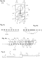
- the inlet pipe 2 has an inflow part 2.2 of length Lz arranged inside the housing 4, which is formed from a plurality of rows of inflow openings 2.3.
- the exhaust gas is deflected in the radial direction via the inflow openings 2.3 and flows out of the inlet pipe 2 in a main flow direction H to the outlet pipe 3.
- the outlet pipe 3 in turn has an outflow part 3.2 of length La, via which the exhaust gas flows from the inside of the housing 4 into the outlet pipe 3 in the radial direction to the A-pipe axis and from there in the axial direction to the outlet pipe 3 via the mix box 1 leaves the outlet 3.8.
- An intermediate wall 9.2 is provided within the housing 4 and is oriented parallel to the main flow direction H.
- the housing 4 has a housing wall 4.3 with an inner side 4i and an outer side 4o, which limits a volume V of the housing 4 with respect to an exhaust gas-free environment G.
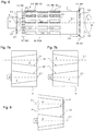
- the housing 4 has a basic shape with a rectangular cross section. In the left half of the picture, an indentation 4.5 is shown inside the housing wall. In addition, the housing wall 4.3 has a rounding 4.7 on the lower left edge.
- the inlet pipe 2 or the inflow part 2.2 has a diameter Dz and the outlet pipe 3 or the outflow part 3.2 has a diameter Da.
- the diameter Dz and / or the diameter Da can, for example, in the respective length Lz, La Figures 7a, 7b shown vary.
- the indentation 4.5 and the rounding 4.7 are shown.
- the guide plate 9.3 forms a taper similar to the indentation 4.5.
- the guide plate 9.1 forms a rounding similar to the rounding 4.7.
- the flow guide elements 9.1, 9.3 are not part of the housing wall 4.3 because they do not serve to limit the volume V in relation to an exhaust gas-free environment G. Because the wall side 9w is arranged within the housing 4 and not in the area.
- a flow zone S extends between the two tubes 2, 3 and extends up to the height of the tube axis 2.1 and downwards to the level of the tube axis 3.1.
- the flow zone S is delimited laterally by two interfaces B1, B2, the interface B1 being arranged at a distance a12 from the pipe axis 2.1 and at a distance a13 from the pipe axis 3.1.
- the boundary surface B2 is arranged at a distance a22 from the pipe axis 2.1 and at a distance a23 from the pipe axis 3.1.
- the distances a12 and / or a22 can vary over the length Lz.
- the distances a13 and / or a23 can vary over the length La.
- the axial extent of the flow zone S corresponds to the axial extent of the inflow part 2.2 or the outflow part 3.2, hence the respective length Lz or length La.
- the interface B2 lies at the level of the guide plate 9.3, which is arranged inside the housing 4. While the flow guide element 9.3 is placed outside the flow zone S, the indentation 4.5 is arranged as part of the housing wall 4.3 within the flow zone S.
- Both the distances r1, r2, r3, r4, r5 between the tubes 2, 3 and the housing wall 4.3 or indentation and, for example, the distance r6 between the tube 3 and the flow guide element 9.1 are shown.
- the wall distances r1 to r4 are of approximately the same size with respect to an axis A1, A2 arranged at right angles to the respective pipe axis 2.1, 3.1.
- the sizes of the wall distances r1 to r4 differ by a maximum of 10% to 30%.
- the interior of the housing 4 is free of flow guiding elements which would influence an inflow of the outlet pipe 3 starting from the inlet pipe 2.
- the indentation 4.5 of the housing wall or the rounding 4.7 at most has an influence. These are easy to manufacture as part of the housing wall.
- the distance r5 is between the outlet pipe 3 and the indentation 4.5.
- the two flow guide elements 9.1, 9.3 are designed in the form of separate guide plates. Although they have a similar effect on the flow, they are separate components that have to be installed separately.
- the distance r6 is shown as an example for the distance between the tube 3 and the flow guide elements 9.1, 9.3.
- the radius Ra of the outlet pipe 3 is approximately 20% larger than the wall distances r1 to r5 or larger than the distance r6 to the flow guide element 9.1.
- the housing 4 has an indentation 4.5 and a rounding 4.7 in the left half of the figure. These ensure that the radial distance r5 between the outlet pipe 3 and the housing wall 4.3 is almost identical over an angular range ⁇ of approximately 140 °. Supplementary to this are after Figure 4b Baffles 9.3, 9.1 are provided, which in turn limit the distance to the outlet pipe 3 to the corresponding dimension r6, so that the angular range ⁇ over which the outlet pipe 3 is approximately the same distance from the next housing wall 4.3 or the next flow guide element 9.1 Figure 4b grows to almost 280 °.
- Corresponding indentations 4.5 and / or roundings 4.7 of the housing wall 4.3 or corresponding flow guide elements 9.3, 9.1 can be provided to ensure the required distances. While according to the definition of the flow zone S, flow guide elements 9.3, 9.1 are not permitted within the flow zone S, this does not apply to the housing wall 4.3 or parts thereof.
- Figure 4c shows a schematic diagram of the length La of the outflow part 3.2, the outflow openings 3.3, which are in the form of mixing rows or mixing stages, being arranged distributed over the entire length La.
- the outflow part 3.2 is in two parts. There are two sections of outflow openings 3.3 or mixing rows or mixing stages, each of which forms part of the outflow part 3.2.
- the length La is therefore the sum of the lengths of both sections.
- FIG 4e different flow zones S are shown within the length La on the one hand and different flow guide elements 9.1, 9.3 on the other hand.
- a flow volume Vs which is defined by the flow zones S, can be formed over approximately 77% of the length La.
- the flow volume Vs is only partially stylized on the right, starting with the first flow zones S.
- the front part of the outflow part 3.2 is blocked by flow guide elements 9.3, so that no flow zone S, but at least no flow volume Vs, can be formed in this area.
- a portion Sf of the flow zones S is free within this flow volume, while a remaining portion Sb is blocked by flow guide elements 9.1.
- Figure 5 shows the schematic diagram of an exhaust system 5 with the Mix Box 1 and connected exhaust pipes 5.1, 5.2, via which the exhaust system is connected to the motor vehicle or an exhaust muffler.
- the outlet pipe 3 has a plurality of rows 3.5 of openings 3.3, an injection nozzle 8 at the inlet 3.7 and an open end at the outlet 3.8.
- the openings 3.3 are each designed as a wing-free recess in the housing wall 4.3.
- the sum of all opening cross sections Q1 of a sector S1 is SQ1.
- the sum of all opening cross sections Q of all openings 3.3 of all rows 3.5 of the outlet pipe 3 is SQ.
- SQ1 ⁇ 0.15 SQ applies to the ratio of SQ1 to SQ.
- a second sector S2 with a plurality of steps M2 formed from a plurality of rows 3.5 of openings 3.3 with a central opening cross section Q2 is provided in the outlet pipe 3.
- the sum of all opening cross sections Q2 of the sector S2 is SQ2.
- the openings 3.3 are designed as a molding of the housing wall 4.3, the molded part of the housing wall 4.3 forming a wing 3.4.
- a third sector S3 is provided with a step M3 with a row 3.5 of openings 3.3 with a central opening cross section Q3. Latter in connection with a conical widening or a cone 3.9 of the outlet pipe 3 at the pipe end or outlet 3.8, so that an enlarged diameter is achieved. All openings 3.3 extend in the circumferential direction U.
- the injection nozzle 8 has a spray cone 8.1, which nominally (without taking into account a flow) has an opening angle ⁇ of approximately 80 °.
- the spray cone 8.1 cuts the outlet pipe 3 at the intersection X, which is arranged within the sector S2.
- both the inlet pipe 2 and the outlet pipe 3 are designed in the shape of a truncated cone in their basic form G1, G2.
- Both tubes 2, 3 are arranged in opposite directions with respect to the alignment along the tube axis 2.1, 3.1, while according to the embodiment according to Figure 8 both tubes 2, 3 are arranged in the same direction.
- the housing 4 has a basic shape which is also frustoconical in cross-section and which can be used in the case of corresponding installation space conditions.
- the formation of a corresponding basic shape or the use of corresponding flow guide elements is necessary in order to ensure the above-mentioned distances a12 to a23 or distances r1 to r6, and consequently symmetrical flow conditions.
- the housing edge 4a, 4b which is not shown in detail, is square, and is therefore point-symmetrical with respect to a normal N of the division plane e, so that the two housing parts 4.1, 4.2 can be pivoted through 90 °.
- the pivoting takes place through 90 ° to the right. Further pivoting options by 180 ° or 270 ° or -90 ° are of course also possible.
- Both tubes 2, 3 are each stored in a pair of passages 7.1 to 7.4.
- FIG 9a To Figure 9a are the first housing half or the first housing part 4.1 and the second housing half or the second housing part 4.2 in the relative position P1.
- FIG. 9b In the embodiment according to Figure 9b are both housing shells 4.1, 4.2 in the relative position P2, rotated by 90 ° to each other. This results in a pivoting of the inlet and outlet pipes 2, 3 by the angle ⁇ by 90 °.
- Figure 9c shows the side view Figure 9b with the division level e and the connected housing edges 4a, 4b.
- the inlet pipe 2 and the outlet pipe 3 are placed in the respective bearing point 2.4, 3.6, which is designed as a passage.
- the two tube axes 2.1, 3.1 are aligned in parallel.
- the tubes 2, 3 are both in the relative position P2 with respect to the respective housing half 4.1, 4.2.
- the in the Figures 10a, 10b Mix box 1 shown has a housing 4 with two housing parts 4.1, 4.2 designed as a housing shell, in each of which four configurations 6.1, 6.2, 6.3, 6.4 (only two each shown) are provided, with an inlet pipe 2 in the configurations 6.1, 6.3 in a position P1 and in the formations 6.2, 6.4 an outlet pipe 3 are arranged in the position P1.
- the respective pipe 2, 3 has bearing points 2.4, 2.5, 3.6, via which it is mounted in the respective shape.
- the respective housing edge 4a, 4b is aligned parallel to the pipe axis 2.1, 3.1. Where the housing edges 4a, 4b can be brought into abutment against one another, they form the parting plane e for the housing 4.
- Both the inlet pipe 2 and the outlet pipe 3 have a pipe axis 2.1, 3.1, which is coaxial with a central axis 6a, 6b of the respective formation pairing 6.1, 6.3 and 6.2, 6.4 is aligned.
- the inlet pipe 2 in contrast to the embodiment of FIG Figure 10a rotated by 180 °.
- the inlet pipe 2 is in a position P2, while the outlet pipe 3 has remained in the position P1.
- the inlet pipe 2 In the area of its bearing points 2.4, 2.5, that is to say in the area of the respective formation 6.1, 6.3, the inlet pipe 2 has diameters D of the same size, so that these are easily rotated through 180 ° can.
- the two housing parts 4.1, 4.2 remain in the same relative position P1 to each other. The same can also be used for the outlet pipe 3.
Landscapes
- Chemical & Material Sciences (AREA)
- Engineering & Computer Science (AREA)
- Chemical Kinetics & Catalysis (AREA)
- Combustion & Propulsion (AREA)
- Mechanical Engineering (AREA)
- General Engineering & Computer Science (AREA)
- Health & Medical Sciences (AREA)
- Toxicology (AREA)
- Exhaust Gas After Treatment (AREA)
- Exhaust Silencers (AREA)
- Exhaust Gas Treatment By Means Of Catalyst (AREA)
Description
- Die Erfindung bezieht sich auf eine Vorrichtung zum Mischen von Abgasen, mithin eine Mix Box für eine Abgasanlage einer Verbrennungskraftmaschine zum Einmischen von Additiven in einen Abgasstrom mit mindestens einem eine E-Rohrachse aufweisenden Einlassrohr, mit mindestens einem eine A-Rohrachse aufweisenden Auslassrohr und mit einem eine Gehäusewand aufweisenden Gehäuse mit einer Innenseite und einer Außenseite zur Aufnahme des endseitig geschlossenen Einlassrohres und des Auslassrohres, wobei das Gehäuse ein Volumen V der Mix Box gegenüber einer Umgebung begrenzt, wobei das Einlassrohr einen innerhalb des Gehäuses angeordneten Zuströmteil mit einem Durchmesser Dz und mit einer Länge Lz aufweist, der zwecks Einleitung des Abgases in das Gehäuse mit mindestens einer Zuströmöffnung versehen ist, wobei das Auslassrohr endseitig eine Dosiervorrichtung und einen innerhalb des Gehäuses angeordneten Ausströmteil mit einem Durchmesser Da und einer Länge La aufweist, der zwecks Ausleitung des Abgases aus dem Gehäuse mit mindestens einer Ausströmöffnung versehen ist, wobei eine Strömungszone S zwischen dem Einlassrohr und dem Auslassrohr vorgesehen ist, die seitlich begrenzt ist durch zwei Grenzflächen B1, B2, die jeweils einen kürzesten Abstand a12, a13, a22, a23 zum jeweiligen Punkt der jeweiligen Rohrachse aufweisen.
- Es ist bereits eine Mischrohranordnung mit Gehäuse aus der
EP 2 687 697 A2 bekannt. Die Anordnung weist ein Einlassrohr sowie ein parallel dazu angeordnetes Auslassrohr auf, die in dem Gehäuse angeordnet sind. Innerhalb eines schneckenförmigen Abschnitts der Gehäusewand ist das Auslassrohr außermittig platziert, sodass ein verjüngender Einlaufspalt gebildet ist. - Zudem ist eine Mischrohranordnung mit Gehäuse aus der
WO 2014/167355 A1 bekannt. Die Anordnung weist ein Auslassrohr auf, das teilweise in dem Gehäuse angeordnet ist. - Aus der
US 2014 0 202 141 A1 ist eine Mischrohranordnung mit Gehäuse bekannt, wobei Einlassrohr und Auslassrohr perforationsfrei und rechtwinklig zueinander ausgerichtet sind. - Aus der
DE 10 2013 114 111 A1 ist bereits ebenfalls eine Mischrohranordnung mit Gehäuse bekannt. Die Anordnung weist auch ein Einlassrohr sowie ein parallel dazu angeordnetes Auslassrohr auf, die in dem Gehäuse angeordnet sind. - Aus der
WO 2015/091242 A1 ist ebenfalls eine Mischrohranordnung mit Gehäuse bekannt. Die Anordnung weist auch ein Einlassrohr sowie ein parallel dazu angeordnetes Auslassrohr auf, die in einem zweiteiligen Gehäuse angeordnet sind. - Aus der
DE 20 2014 102 872 U1 ist bereits ein Mischrohr zur alleinigen Anwendung in einer Mischrohranordnung bekannt. - Aus der
EP 2 687 697 A2 ist bereits eine Mischvorrichtung zur Nachbehandlung von Abgasen bekannt. Die Mischvorrichtung weist ein Gehäuse mit einer Eintrittsöffnung sowie einem perforierten Innenrohr auf. Das Gehäuse weist einen spiralförmigen Gehäuseabschnitt auf, über den das eintretende Abgas zum Innenrohr geführt wird. - Der Erfindung liegt die Aufgabe zugrunde, eine Mischrohranordnung derart auszubilden und anzuordnen, dass trotz einfachen Aufbaus eine optimale Einmischung erreicht wird.
- Gelöst wird die Aufgabe erfindungsgemäß dadurch, dass über mindestens 30 % bis 50 % der Länge La mindestens ein Anteil Sf von 70 % der Strömungszonen S frei von Strömungsleitelementen ist, wobei ein Strömungsleitelement eine Strömungsumlenkung in eine Richtung R radial zu der A-Rohrachse bewirkt und das Strömungsleitelement eine Wandseite und eine Gasseite aufweist, die beide innerhalb des Volumens V angeordnet sind. Die jeweilige Strömungszone S zwischen dem Zuströmteil und dem Ausströmteil liegt in der zu betrachtenden Schnittebene, die meist rechtwinklig zur A-Rohrachse platziert ist. Die Strömungszone S endet oben auf der Höhe der E-Rohrachse und unten auf der Höhe der A-Rohrachse. Seitlich endet die Strömungszone S an den beiden Grenzflächen B1, B2. Die Summe aller Strömungszonen S der verschiedenen Schnittebenen spannt ein Strömungsvolumen Vs als Teil des Gehäusevolumens auf.
- Strömungsleitelemente sind Bauteile innerhalb des Volumens V, die die Gehäusewand auf der Innenseite ergänzen und die einen nicht unwesentlichen Einfluss auf die Ablenkung der Abgasströmung in Umfangsrichtung U zur A-Rohrachse und/oder in eine Richtung R radial zur A-Rohrachse haben. Teile der Gehäusewand, die das Volumen V der Mix Box nach außen begrenzen, sind nicht als Strömungsleitelemente im Sinne der Erfindung anzusehen. Dies gilt auch, wenn diese Teile der Gehäusewand innerhalb der Strömungszone S angeordnet sind. Strömungsleitelemente kennzeichnen sich dadurch aus, dass sowohl ihre der nächsten Gehäusewand zugewendete Wand- bzw. Außenseite als auch ihre der Hauptgasströmung zugewandte Gas- bzw. Innenseite innerhalb des Gehäuses im Volumen V angeordnet sind.
- Es soll ein möglichst großes Strömungsvolumen bereit gestellt sein, innerhalb dessen die Strömungszonen S frei von Strömungsleitelementen sind. Dies wird erreicht durch zwei Bedingungen. Zum einen sollte sich das Strömungsvolumen über mindestens 30 % bis 50 % der Länge La erstrecken, mithin sollten möglichst viele Strömungszonen S frei von Strömungsleitelementen sein, sodass das Abgas ohne eine Umlenkung in radialer Richtung R vom Einlassrohr in das Auslassrohr strömen kann. Wenn innerhalb dieses Anteils von 30 % bis 50 % der Länge La ein geringer Teil Sb der Strömungszonen S durch ein Strömungsleitelement blockiert ist, mithin unfrei ist, so ist das nicht nachteilig. Zum anderen sollte jedoch dieser Anteil Sb 30 % nicht erreichen, mithin mindestens ein Anteil von Sf = 70 % frei sein. Im Ergebnis wird demnach gefordert, dass mit Bezug zur Länge La über mindestens 21 % des Ausströmteils die Strömungszonen S frei sein müssen.
- Der Ausströmteil ist der Teil des Auslassrohres, der die mindestens eine Ausströmöffnung aufweist. In der Regel sind mehrere Ausströmöffnungen in Form einer Reihe vorgesehen, die über den Umfang U verteilt sind. Sollte das Auslassrohr einen Ausströmteil aufweisen, der wesentlich kürzer ist als der im Gehäuse befindliche Teil des Auslassrohres, so ist bei der Beurteilung des Anteils der Länge La, der frei von Strömungsleitelementen ist, auf die Summe der Längen der verschiedenen Reihen von Ausströmöffnungen abzustellen, die zusammen die Länge des Ausströmteils bilden.
- Vorteilhaft kann es hierzu auch sein, wenn für den jeweiligen Abstand a12, a13, a22, a23 gilt:
0 < a12 <= x1 Dz und 0 < a13 <= x2 Da und 0 < a22 <= x3 Dz und 0 < a23 <= x4 Da, wobei der jeweilige Wert x1, x2, x3, x4 ein Element der Zahlengruppe {2; 1,5; 1; 1/2; 1/4} ist, wobei die jeweiligen Abstände a12, a13, a22, a23 unterschiedlich groß sein können und/oder über die jeweilige Länge Lz, La variieren können. - Gelöst wird die Aufgabe auch erfindungsgemäß dadurch, dass
- a) das Auslassrohr einen Rohrradius Ra = Da/2 und einen radialen Abstand r1, r2, r5, r6 zur Innenseite der Gehäusewand und/oder zu einem Strömungsleitelement aufweist, wobei
mit Bezug zu einem Winkelbereich β von mindestens 90° bis 270° oder von mindestens 160° bis 200° um die A-Rohrachse- ai) der Abstand r6 zum nächsten Strömungsleitelement und/oder der Abstand r5 zur nächsten Gehäusewand gleich ist oder maximal um 10 % bis 30 % abweicht und/oder
- aii) dass ein Strömungsleitelement vorgesehen ist und das Verhältnis von Rohrradius Ra zum Abstand r6 zwischen dem Auslassrohr und dem Strömungsleitelement maximal sechs oder maximal drei ist oder
- b) der Zuströmteil und der Ausströmteil ein Volumen V23 begrenzen und ein Differenzvolumen V1 = V - V23 bzw. das Volumen V die folgende Bedingung erfüllt: V1 >= 1,2 V23. Das Volumen V1 ist demnach mindestens 20 % größer als das Volumen V23 als Summe der Volumen des Zuströmteils und des Ausströmteils. Das Volumen V23 der beiden Rohre ergibt sich aus der Summe der Volumen beider Rohre. V23 = π/4 (Lz Dz Dz + La Da Da). Durch Anwendung eines entsprechend großen Gehäuses wird eine Vergleichmäßigung der Abgasströmung insbesondere beim Einströmen in das Auslassrohr bzw. den Zuströmteil gewährleistet.
- Für den Winkelbereich β kann der Strömungsfaden F als Ausgangspunkt oder als Winkelhalbierende gewählt werden, so dass innerhalb des entsprechenden Sektors die genannten Abstände bzw. Verhältnisse vorgesehen sind.
- Da Zuströmöffnungen und Ausströmöffnungen auch als Klappen oder Ausformungen ausgebildet sein können, die nach innen und/oder nach außen gerichtet sind, wird bei der Angabe des Durchmessers Dz, Da sowie bei dem Radius Ra abgestellt auf den mittleren Durchmesser bzw. den Durchmesser der ursprünglichen Rohrwand ohne Klappen oder Ausformungen.
- Eine Mindestgröße für die Strömungszone S wäre erreicht, wenn ein Teil der Gehäusewand als Strömungsleitelement ausgebildet ist und/oder wenn weitere Strömungsleitelemente in Form von Leitblechen vorgesehen sind, wobei eine direkte Strömungsverbindung zwischen dem Einlassrohr und dem Auslassrohr in Bezug auf zumindest einen Strömungsfaden F in Richtung eines Strömungsvektors T vorgesehen ist, wobei der Strömungsvektor T die E-Rohrachse und die A-Rohrachse verbindet.
- Durch die vorstehend genannten Maßnahmen wird eine im Wesentlichen direkte und eine achsen- bzw. spiegelsymmetrische Anströmung des Auslassrohres erreicht und unterstützt. Das Auslassrohr sitzt vis-à-vis zum Einlassrohr symmetrisch in dem es umgebenden Gehäuseteil. Somit kann ein maßgeblicher Teil der Abgasströmung ausgehend vom Einlassrohr bzw. den Einströmöffnungen ohne eine Umlenkung durch Strömungsleitelemente wie die Gehäusewand oder Leitbleche unmittelbar zum Auslassrohr strömen. Hierdurch bildet sich eine überwiegend drall- und wirbelfreie Strömung innerhalb des Gehäuses aus, die maßgeblich durch die Zuströmöffnungen definiert wird. Diese Abgasströmung kann dann in das Auslassrohr eintreten. Die Ausprägung der Strömung innerhalb des Auslassrohres wird somit maßgeblich durch die Geometrie des Ausströmteils bzw. der Ausströmöffnung bestimmt. Dies wiederum gewährleistet eine optimale Einmischung des Additivs.
- Das Gehäuse kann vorteilhafterweise eine kubische oder zylindrische Grundform mit einem Zylinderradius Z aufweisen, wobei mindestens 80 % bis 90 % der Flächenanteile der Gehäusewand entweder flach ausgebildet sind oder einen dem Zylinderradius Z entsprechenden Krümmungsradius K aufweisen. Ein solches einfach gestaltetes Gehäuse bildet die Grundlage für eine möglichst unbeeinflusste Abgasströmung innerhalb des Gehäuses zwischen dem Einlassund dem Auslassrohr.
- Außerdem kann es vorteilhaft sein, wenn der Ausströmteil auf seiner Außenseite um 360° umströmbar ist. Hierbei ist ein Abstand zur Gehäusewand von mindestens Da/8 bis Da/4 vorgesehen. Mithin wird die Symmetrie der Einströmung in den Ausströmteil des Auslassrohres gewährleistet.
- Für das Verhältnis der Rohrgrößen kann es von Vorteil sein, wenn für den Durchmesser Da gilt: 0,8 Dz <= Da <= 1,5 Dz. Dies gilt im Falle einer vom Zylinder abweichenden Form der Rohre sowohl für den jeweils in Betracht gezogenen Querschnitt, mithin punktweise oder alternativ einen über die Länge Lz, La gemittelten Durchmesser Dz, Da.
- Grundsätzlich ist es möglich, dass die Durchmesser Dz, Da über die Länge Lz, La variieren. Dies ist aber für die Definition der erfindungsgemäßen Lehre, mithin die Definition der Grenzflächen B1, B2 sowie der Abstände a12, a22, a13, a23, r1, r2, r3, r4, r5 unbeachtlich. Je nach angewendetem Querschnitt bzw. Schnittpunkt der Schnittebene findet eine Betrachtung der geometrischen Verhältnisse in der jeweiligen Schnittebene statt.
- Vorteilhaft kann es hierzu auch sein, wenn eine Dosiervorrichtung wie eine Einspritzdüse vorgesehen ist, die koaxial zum Auslassrohr angeordnet ist, wobei die Einspritzdüse einen Sprühwinkel δ aufweist, mit 5° <= δ <= 80° oder 10° <= δ <= 60°. Hierbei handelt es sich um die nominale Größe des Sprühwinkels δ, d. h. gemessen ohne Abgasströmung. Der Sprühwinkel δ ist derart gewählt, dass ein Schnittpunkt X mit der Rohrwand innerhalb des Mischsektors S2 nach dem Spülsektor S1 liegt.
- Ferner kann es vorteilhaft sein, wenn das Auslassrohr die Gehäusewand an zwei gegenüberliegenden Positionen durchdringt. Somit sind die Anordnung der endseitigen Dosiervorrichtung einerseits sowie die Ausleitung des Abgases auf der der Dosiervorrichtung gegenüberliegenden Seite andererseits möglich.
- Vorteilhaft kann es auch sein, wenn das Auslassrohr im Bereich einer oder mehrerer Ausströmöffnungen jeweils einen mindestens einseitig angelenkten Flügel aufweist, der nach innen oder außen in radialer Richtung übersteht. Wenn der Flügel klappenartig ausgebildet ist weist er eine gerade Biegekante auf. Ausgehend von einer rechteckförmigen Grundform kann dieser somit drei freie Seiten aufweisen, sodass das Abgas den Flügel über mindestens 60 % bis 80% seines Umfangs über die freie Kante umströmen und in die Ausströmöffnung eintreten kann. Alternativ können auch Schaufeln vorgesehen sein, die eine abgerundete Anbindung an die Rohrwand aufweisen, die in der Regel länger ist als eine gerade Biegekante. Das Abgas kann den Flügel in diesem Fall nur über einen kleineren Teil seines Umfangs über die freie Kante umströmen und in die Ausströmöffnung eintreten.
- Dabei kann es vorteilhafterweise vorgesehen sein, dass im Einlassrohr der Grad der Perforation in Strömungsrichtung abnimmt. Somit nimmt der eintretende Volumenstrom in Richtung zu der Dosiervorrichtung zu, was zu einer verbesserten Einmischung führt.
- Von besonderer Bedeutung kann für die vorliegende Erfindung sein, wenn eine Zwischenwand vorgesehen ist, die parallel zu einer Hauptströmungsrichtung H ausgerichtet ist. Die Zwischenwand dient der Stabilisierung des Gehäuses bzw. zur Lagerung der Rohre. Eine nachteilige Beeinflussung der Abgasströmung innerhalb des Gehäuses zwischen dem Einlass- und dem Auslassrohr findet somit nicht statt. Es werden durch die Zwischenwand lediglich Strömungsanteile eliminiert mit einer Richtungskomponente parallel zur E- oder A-Rohrachse. Dies wiederum trägt zur Ausbildung einer beruhigten Strömung zwischen beiden Rohren bei.
- Im Zusammenhang mit der erfindungsgemäßen Ausbildung und Anordnung kann es von Vorteil sein, wenn das Einlassrohr eine kegelstumpfförmige Grundform G1 aufweist und/oder das Auslassrohr eine kegelstumpfförmige Grundform G2 aufweist, wobei das Einlassrohr und das Auslassrohr mit Bezug auf die Grundform G1, G2 gleichsinnig oder gegensinnig ausgerichtet sind. Im Falle einer gleichsinnigen Ausrichtung der Rohre kann das Gehäuse selbst bzw. der Querschnitt des Gehäuses auch kegelstumpfförmig ausgebildet sein.
- Vorteilhaft kann es ferner sein, wenn das Gehäuse aus maximal zwei oder drei Gehäuseteilen gebildet ist und mindestens einen Verbindungsflansch für beide Gehäuseteile aufweist. Dies gewährleistet einen einfachen Aufbau einerseits und günstige Montageverhältnisse für die Rohre andererseits. Beide Gehäuseteile können aus dem gleichen Schalenrohling hergestellt werden. Mit Ausnahme von Sonderbauformen wie Steckflansche hat in der Regel jedes Gehäuseteil einen eigenen Flansch, sodass beide Flansche zum Koppeln der beiden Gehäuseteile miteinander verbunden werden.
- Möglich ist es hierzu auch, wenn das Gehäuse ein erstes Gehäuseteil mit einem ersten Gehäuserand und mindestens ein zweites Gehäuseteil mit einem zweiten Gehäuserand aufweist, wobei beide Gehäuseteile über den eine Teilungsebene e aufspannenden Gehäuserand zumindest teilweise verbunden sind, wobei der Gehäuserand mit Bezug zu einer Normalen N der Teilungsebene e punktsymmetrisch oder mit Bezug zu einer Geraden G der Teilungsebene e achssymmetrisch ausgebildet ist. Während die achssymmetrische Ausbildung des Gehäuserandes bzw. des Flansches eine Variation der relativen Lage beider Gehäuseteile in zwei Positionen verschwenkt um 180° zulässt, gewährleistet die punktsymmetrische Ausbildung zumindest eine Variation innerhalb von mindestens vier Positionen, also stufenweise um 90°.
- Ferner kann es vorteilhaft sein, wenn das Auslassrohr mehrere über einen Umfang U angeordnete Reihen von Ausströmöffnungen aufweist, durch die Abgas in das Innere des Auslassrohres strömen kann, wobei die mindestens eine Ausströmöffnung einer Reihe jeweils eine Stufe M bildet und wobei die jeweilige Stufe M ihrer Größe nach gekennzeichnet ist durch den mittleren Öffnungsquerschnitt Q der Öffnungen, wobei die Summe aller Öffnungsquerschnitte Q aller Ausströmöffnungen aller Reihen des Auslassrohres gleich SQ ist, wobei mindestens eine Stufe erster Ordnung, die Stufe M1, vorgesehen ist, wobei die Stufe M1 Ausströmöffnungen mit einem mittleren Öffnungsquerschnitt Q1 aufweist, und wenn zudem mindestens eine Stufe zweiter Ordnung, die Stufe M2, vorgesehen ist, wobei die Stufe M2 Ausströmöffnungen mit einem mittleren Öffnungsquerschnitt Q2 mit Q2 >= f Q1, mit 5 <= f <= 25 aufweist, und wenn ein erster Sektor S1 vorgesehen ist, der als Spülsektor ausgebildet ist und aus mindestens der einen Stufe M1 gebildet ist, und wenn ein zweiter Sektor S2 vorgesehen ist, der als Mischsektor ausgebildet ist und aus mindestens der einen Stufe M2 gebildet ist, wobei in Strömungsrichtung zunächst der erste Sektor S1 und danach der zweite Sektor S2 platziert ist. Durch die Anordnung von zwei Sektoren S1, S2 mit unterschiedlichen Öffnungsquerschnitten wird eine Spülwirkung des Sektors S1 erreicht, durch die Rückspüleffekte im Bereich der Dosiervorrichtung bzw. Düse verhindert werden. Durch den kleineren Öffnungsquerschnitt Q1 wird lediglich eine Mantelströmung innerhalb des Auslassrohres realisiert. Dies wiederum gewährleistet die Einmischung des Additivs in den Hauptabgasstrom in Sektor 2, dessen Öffnungsquerschnitte wesentlich größer sind.
- Dabei kann es von Vorteil sein, wenn der Sektor S1 eine Summe SQ1 der Öffnungsquerschnitte Q1 mit SQ1 <= x1 SQ, mit 0,05 <= x1 <= 0,25 aufweist und/oder wenn der Sektor S1 aus maximal drei bis fünf Stufen M1 gebildet ist. Ergänzend zu den kleineren Öffnungsquerschnitten ist die Öffnungsgröße insgesamt reduziert, damit der Spüleffekt noch besser zum Tragen kommt. Der Sektor S1 ist vorzugsweise flügelfrei.
- Weiterhin kann es von Vorteil sein, wenn ein Sprühkegel mit einem Sprühwinkel δ vorgesehen ist, wobei der Sprühwinkel δ derart gewählt ist, dass ein Schnittpunkt X zwischen dem Sprühkegel und dem Auslassrohr in Strömungsrichtung nach dem ersten Sektor S1 und/oder innerhalb des zweiten Sektors S2 vorgesehen ist. Somit wird die Spülwirkung unterstützt. Ein Niederschlag von Additiv im Düsenbereich wird verhindert.
- Schließlich kann es auch vorteilhaft sein, wenn das Gehäuse ein erstes Gehäuseteil mit einem ersten Gehäuserand und mindestens ein zweites Gehäusetel mit einem zweiten Gehäuserand aufweist, wobei beide Gehäuseteile über den Gehäuserand zumindest teilweise verbunden sind, und wenn das Einlassrohr einen innerhalb des Gehäuses angeordneten Zuströmteil aufweist, der zwecks Einleitung des Abgases in das Gehäuse mit mindestens einer Zuströmöffnung versehen ist, wobei
- a) der jeweilige Gehäuserand mindestens zwei Ausformungen mit je einer Mittelachse aufweist und/oder
- b) das jeweilige Gehäuseteil mindestens zwei Durchzüge mit je einer Mittelachse aufweist
und das jeweilige Rohr Lagerstellen aufweist, über die es innerhalb der Ausformungen oder innerhalb der Durchzüge gelagert ist, wobei- i) das jeweilige Rohr bezüglich der Ausbildung der Lagerstellen symmetrisch ausgebildet ist und zwecks Montage in mindestens zwei verschiedenen Positionen P1, P2 in der jeweiligen Ausformung lagerbar ist oder
- ii) das Einlassrohr und das Auslassrohr bezüglich der Ausbildung der Lagerstellen gleich ausgebildet sind.
- Hierdurch wird erreicht, dass die relative Lage zwischen dem jeweiligen Rohr und dem Gehäuse und/oder die relative Lage der Rohre innerhalb des Gehäuses variiert werden kann. Diese Variation lässt sich wie folgt erreichen:
- i) Durch unterschiedliche Ausrichtung des Einlassrohres oder des Auslassrohres in Bezug auf dieselbe Ausformung oder denselben Durchzug. Das Einlassrohr bzw. das Auslassrohr kann wahlweise gedreht werden, um die Ausrichtung von Ein- und Auslass des Rohres, mithin die Abgasführung zu verändern. Diese Lageänderung kann nur für das Einlassrohr oder nur für das Auslassrohr Anwendung finden.
- ii) Durch Vertauschen der Position des Einlassrohres mit der Position des Auslassrohres innerhalb des Gehäuses. Ergänzend zu Variante i) können durch das Vertauschen weitere Ausgestaltungsvarianten des Mischers bzw. dessen Gasführungsgeometrie erreicht werden. Somit sind die Mittelachsen von jeweils zwei Ausformungen oder von zwei Durchzügen mit der E-Rohrachse und mit der A-Rohrachse in Überdeckung bringbar, sodass alternativ das Einlassrohr oder das Auslassrohr bezüglich der jeweiligen Position P1, P2 in der Gehäuseschale bzw. in dem Gehäuseteil oder in dem Gehäuseboden lagerbar ist.
- iii) Durch eine Veränderung der relativen Lage beider Gehäuseteile bzw. Gehäuseschalen zueinander. In diesem Fall kann insbesondere beim Einsatz von Durchzügen die Gasführungsgeometrie unabhängig von der flexiblen Lagerung der Rohre nach den Varianten i) und ii) erreicht werden. Die in der jeweiligen Schale bzw. in dem Gehäuseboden angeordneten Rohre bzw. die damit einhergehende Gasführungsgeometrie wird durch Veränderung der relativen Lage beider Gehäuseschalen bzw. Gehäusewände zueinander variiert. Für die relativen Positionen P1, P2 kommt nicht nur ein rechter Winkel, sondern auch beliebige Winkel in Betracht.
- Die Ausformung des jeweiligen Gehäuserandes gewährleistet eine Aufnahme des jeweiligen Rohres über jeweils einen Teilumfang von ca. 180°, sodass durch beide gegenüberliegende Ausformungen wie auch beim Durchzug eine Lagerung und Abdichtung des jeweiligen Rohres über den Umfang U gewährleistet ist.
- Weitere Vorteile und Einzelheiten der Erfindung sind in den Patentansprüchen und in der Beschreibung erläutert und in den Figuren dargestellt. Es zeigt:
- Figur 1
- eine Prinzipskizze der Mix Box mit kubischer Grundform;
- Figur 2
- eine Prinzipskizze der Mix Box mit zylindrischer Grundform;
- Figur 3
- die Prinzipskizze einer Schnittdarstellung gem.
Fig. 1 oder 2 ; - Figur 4a
- eine Prinzipskizze der Schnittdarstellung y - y aus
Fig. 3 ; - Figur 4b
- eine Schnittdarstellung nach
Figur 4a mit weiteren Kenngrößen; - Figur 4c
- eine Prinzipskizze zur Länge La;
- Figur 4d
- eine weitere Prinzipskizze zur Länge La;
- Figur 4e
- eine Prinzipskizze zum Anteil Sf und Sa der Strömungszonen S;
- Figur 5
- eine Prinzipskizze einer Abgasanlage;
- Figur 6
- die Prinzipskizze eines Auslassrohres in der Seitenansicht;
- Figuren 7a - 8
- die Prinzipskizze der Mix Box mit kegelstumpfförmigen Rohren;
- Figuren 9a, 9b
- die Mix Box in der Ansicht von oben;
- Figur 9c
- die Mix Box nach
Figur 9b in der Seitenansicht; - Figuren 10a, 10b
- die Mix Box in der Seitenansicht mit geänderter Gehäuseteilung.
- Eine Mix Box 1 nach
Figur 1 ist aus zwei Gehäuseteilen 4.1, 4.2 mit je einem Gehäuserand 4a, 4b gebildet, die über einen Verbindungsflansch 4.4 miteinander gekoppelt sind. Innerhalb des ersten Gehäuseteils 4.1 ist ein Einlassrohr 2 mit einem Einlass E für Abgas angeordnet, während in dem zweiten Gehäuseteil 4.2 ein Auslassrohr 3 mit einem Auslass A platziert ist. Das jeweilige Gehäuseteil 4.1, 4.2 weist entsprechende Durchzüge auf, innerhalb derer die Rohre 2, 3 gelagert sind. Endseitig weist das Auslassrohr 3 eine Spritzdüse 8 auf, über die ein Additiv in das Auslassrohr 3 eingebracht werden kann. Auslassseitig ist am Auslassohr 3 vorzugsweise ein Drallmischer 10 platziert. - Gemäß
Figur 2 ist der Verbindungsflansch 4.4 der zylindrischen Grundform nach rund ausgebildet, während beide Gehäuseteile 4.1, 4.2 einen Krümmungsradius K, der dem Zylinderradius Z entspricht, aufweisen. - In der Schnittdarstellung nach
Figur 3 ist gezeigt, dass das Einlassrohr 2 einen innerhalb des Gehäuses 4 angeordneten Zuströmteil 2.2 der Länge Lz aufweist, der aus mehreren Reihen von Zuströmöffnungen 2.3 gebildet ist. Ausgehend vom Einlass E der Mix Box 1 und der axialen Einströmung wird das Abgas über die Zuströmöffnungen 2.3 in radiale Richtung umgelenkt und strömt aus dem Einlassrohr 2 einer Hauptströmrichtung H nach zum Auslassrohr 3 aus. Das Auslassrohr 3 weist wiederum einen Ausströmteil 3.2 der Länge La auf, über den das Abgas ausgehend von dem Inneren des Gehäuses 4 in das Auslassrohr 3 in radialer Richtung zur A-Rohrachse einströmt und von dort in axialer Richtung zum Auslassrohr 3 die Mix Box 1 über den Auslass 3.8 verlässt. Innerhalb des Gehäuses 4 ist eine Zwischenwand 9.2 vorgesehen, die parallel zur Hauptströmrichtung H ausgerichtet ist. - Nach
Figur 4a ,4b , Schnittdarstellung y - y ausFigur 3 , weist das Gehäuse 4 eine Gehäusewand 4.3 mit einer Innenseite 4i und einer Außenseite 4o auf, die ein Volumen V des Gehäuses 4 gegenüber einer abgasfreien Umgebung G begrenzt. Das Gehäuse 4 weist eine im Querschnitt rechteckförmige Grundform auf. In der linken Bildhälfte ist eine Einbuchtung 4.5 innerhalb der Gehäusewand dargestellt. Zudem weist die Gehäusewand 4.3 am linken unteren Rand eine Abrundung 4.7 auf. Das Einlassrohr 2 bzw. der Zuströmteil 2.2 weist einen Durchmesser Dz und das Auslassrohr 3 bzw. der Ausströmteil 3.2 einen Durchmesser Da auf. Der Durchmesser Dz und/oder der Durchmesser Da können über die jeweilige Länge Lz, La wie beispielhaft in denFiguren 7a, 7b dargestellt variieren. - In der rechten Bildhälfte sind zwei Alternativen für die Einbuchtung 4.5 und die Abrundung 4.7 dargestellt. Innerhalb des Gehäuses 4 sind zwei Strömungsleitelemente 9.1, 9.3 mit jeweils einer innenliegenden Gasseite 9g und einer Wandseite 9w in Form gesonderter Leitbleche vorgesehen. Das Leitblech 9.3 bildet eine Verjüngung ähnlich wie die Einbuchtung 4.5. Das Leitblech 9.1 bildet eine Verrundung ähnlich wie die Abrundung 4.7.
- Die Strömungsleitelemente 9.1, 9.3 sind nicht Teil der Gehäusewand 4.3, weil sie nicht dazu dienen, das Volumen V gegenüber einer abgasfreien Umgebung G zu begrenzen. Denn die Wandseite 9w ist innerhalb des Gehäuses 4 angeordnet und nicht in der Umgebung.
- Nach
Figur 4a sind sowohl das Einlassrohr 2 als auch das Auslassrohr 3 symmetrisch innerhalb des Gehäuses 4 platziert. Zwischen den beiden Rohren 2, 3 erstreckt sich eine Strömungszone S, die nach oben bis auf die Höhe der Rohrachse 2.1 und nach unten bis auf die Höhe der Rohrachse 3.1 reicht. Seitlich wird die Strömungszone S begrenzt durch zwei Grenzflächen B1, B2, wobei die Grenzfläche B1 mit Abstand a12 zur Rohrachse 2.1 und mit Abstand a13 zur Rohrachse 3.1 angeordnet ist. Die Grenzfläche B2 ist mit Abstand a22 zur Rohrachse 2.1 und mit Abstand a23 zur Rohrachse 3.1 angeordnet. Die Abstände a12 und/oder a22 können über die Länge Lz variieren. Alternativ oder ergänzend können die Abstände a13 und/oder a23 über die Länge La variieren. - Die axiale Ausdehnung der Strömungszone S entspricht der axialen Ausdehnung des Zuströmteils 2.2 bzw. des Ausströmteils 3.2, mithin der jeweiligen Länge Lz bzw. Länge La.
- Für den jeweiligen Abstand a12, a13, a22, a23 gilt: 0 < a12 <= x1 Dz und 0 < a13 <= x2 Da und 0 < a22 <= x3 Dz und 0 < a23 <= x4 Da, wobei der jeweilige Wert x1, x2, x3, x4 nach
Figur 4a etwa bei 0,3 liegt. - Betreffend die Grenzfläche B2 in
Figur 4a sind die Abstände a22, a23 maximiert. Die Grenzfläche B2 liegt auf Höhe des Leitbleches 9.3, das innerhalb des Gehäuses 4 angeordnet ist. Während das Strömungsleitelement 9.3 außerhalb der Strömungszone S platziert ist, ist die Einbuchtung 4.5 als Teil der Gehäusewand 4.3 innerhalb der Strömungszone S angeordnet. - Nach
Figur 4b sind sowohl die Abstände r1, r2, r3, r4, r5 zwischen den Rohren 2, 3 und der Gehäusewand 4.3 bzw. Einbuchtung als auch beispielhaft der Abstand r6 zwischen dem Rohr 3 und dem Strömungsleitelement 9.1 dargestellt. Die Wandabstände r1 bis r4 sind mit Bezug auf eine rechtwinklig zur jeweiligen Rohrachse 2.1, 3.1 angeordnete Achse A1, A2 etwa gleich groß ausgebildet. Die Größen der Wandabstände r1 bis r4 weichen maximal um 10 % bis 30 % ab. In der linken Bildhälfte ist das Innere des Gehäuses 4 frei von Strömungsleitelementen, die eine Anströmung des Auslassrohres 3 ausgehend von dem Einlassrohr 2 beeinflussen würden. Einen Einfluss hat allenfalls die Einbuchtung 4.5 der Gehäusewand bzw. die Abrundung 4.7. Diese sind als Teil der Gehäusewand auf einfache Weise herzustellen. Zwischen dem Auslassrohr 3 und der Einbuchtung 4.5 liegt der Abstand r5 vor. - In der rechten Bildhälfte sind die beiden Strömungsleitelemente 9.1, 9.3 in Form gesonderter Leitbleche ausgebildet. Sie haben zwar ähnliche Wirkung auf die Strömung, stellen aber gesonderte Bauteile dar, die gesondert montiert werden müssen. Für den Abstand zwischen dem Rohr 3 und den Strömungsleitelementen 9.1, 9.3 ist der Abstand r6 beispielhaft eingezeichnet.
- Der Radius Ra des Auslassrohres 3 ist etwa 20 % größer als die Wandabstände r1 bis r5 bzw. größer als der Abstand r6 zum Strömungsleitelement 9.1.
- Damit die symmetrische Anordnung des Auslassrohres 3 innerhalb des Gehäuses 4 verbessert ist, weist das Gehäuse 4 in der linken Bildhälfte eine Einbuchtung 4.5 sowie eine Abrundung 4.7 auf. Diese gewährleisten, dass der radiale Abstand r5 zwischen dem Auslassrohr 3 und der Gehäusewand 4.3 über einen Winkelbereich β von etwa 140° nahezu identisch ist. Ergänzend hierzu sind nach
Figur 4b Leitbleche 9.3, 9.1 vorgesehen, die wiederum den Abstand zum Auslassrohr 3 auf das entsprechende Maß r6 beschränken, sodass der Winkelbereich β, über den das Auslassrohr 3 annähernd gleichen Abstand zur nächsten Gehäusewand 4.3 bzw. zum nächsten Strömungsleitelement 9.1 aufweist, nachFigur 4b auf fast 280° anwächst. Lediglich der nach oben gerichtete und zum Einlassrohr 2 hin ausgerichtete Teil des Auslassrohres 3 weist einen deutlich größeren Abstand zur übrigen Gehäusewand 4.3 auf. Dieser Bereich wiederum ist vis-à-vis zum Einlassrohr 2 angeordnet, sodass ein Stromfaden F, der sich entlang eines Strömungsvektors T bewegt, ungehindert vom Einlassrohr 2 zum Auslassrohr 3 strömen kann. Der Strömungsvektor T wiederum verbindet die beiden Rohrachsen 2.1, 3.1. Darüber hinaus sind weitere Stromfäden möglich, über die die Abgasströmung ausgehend vom Einlassrohr 2 ohne weitere Umlenkung zum Auslassrohr 3 strömen kann. - Zur Gewährleistung der geforderten Abstände können entsprechende Einbuchtungen 4.5 und/oder Abrundungen 4.7 der Gehäusewand 4.3 oder entsprechende Strömungsleitelemente 9.3, 9.1 vorgesehen sein. Während nach der Definition der Strömungszone S Strömungsleitelemente 9.3, 9.1 innerhalb der Strömungszone S nicht zulässig sind, gilt dies für die Gehäusewand 4.3 oder Teile davon nicht.
-
Figur 4c zeigt eine Prinzipdarstellung der Länge La des Ausströmteils 3.2, wobei die Ausströmöffnungen 3.3, die als Mischreihen oder Mischstufen vorliegen, über die gesamte Länge La verteilt angeordnet sind. - Nach
Figur 4d ist der Ausströmteil 3.2 zweiteilig. Es sind zwei Abschnitte von Ausströmöffnungen 3.3 bzw. Mischreihen oder Mischstufen vorgesehen, die jeweils einen Teil des Ausströmteils 3.2 bilden. Die Länge La ist demnach die Summe der Längen beider Abschnitte. - In
Figur 4e sind verschiedene Strömungszonen S innerhalb der Länge La einerseits und verschiedene Strömungsleitelemente 9.1, 9.3 andererseits dargestellt. Über etwa 77 % der Länge La ist ein Strömungsvolumen Vs ausbildbar, welches durch die Strömungszonen S definiert ist. Das Strömungsvolumen Vs ist auf der rechten Seite beginnend mit der ersten Strömungszonen S nur teilweise stilisiert dargestellt. Der vordere Teil des Ausströmteils 3.2 ist durch Strömungsleitelemente 9.3 blockiert, so dass in diesem Bereich keine Strömungszone S, zumindest aber kein Strömungsvolumen Vs ausbildbar ist. Innerhalb dieses Strömungsvolumens ist ein Anteil Sf der Strömungszonen S frei, während ein übriger Teil Sb durch Strömungsleitelemente 9.1 blockiert ist. -
Figur 5 zeigt die Prinzipskizze einer Abgasanlage 5 mit der Mix Box 1 und daran angeschlossenen Abgasrohren 5.1, 5.2, über die die Abgasanlage mit dem Kraftfahrzeug bzw. einem Abgasendschalldämpfer verbunden ist. - Nach
Figur 6 weist das Auslassrohr 3 mehrere Reihen 3.5 von Öffnungen 3.3, eine Einspritzdüse 8 am Einlass 3.7 und ein offenes Ende am Auslass 3.8 auf. Zudem ist ein erster Sektor S1 mit zwei Reihen 3.5 von Öffnungen 3.3 mit einem mittleren Öffnungsquerschnitt Q1, mithin zwei Stufen M1 erster Ordnung vorgesehen. Die Öffnungen 3.3 sind jeweils als flügelfreie Ausnehmung der Gehäusewand 4.3 ausgebildet. Die Summe aller Öffnungsquerschnitte Q1 eines Sektors S1 ist SQ1. Die Summe aller Öffnungsquerschnitte Q aller Öffnungen 3.3 aller Reihen 3.5 des Auslassrohres 3 ist SQ. Für das Verhältnis von SQ1 zu SQ gilt zunächst SQ1 <= 0,15 SQ. - Zudem ist im Auslassrohr 3 ein zweiter Sektor S2 mit mehreren Stufen M2 gebildet aus mehreren Reihen 3.5 von Öffnungen 3.3 mit einem mittleren Öffnungsquerschnitt Q2 vorgesehen. Die Summe aller Öffnungsquerschnitte Q2 des Sektors S2 ist SQ2. Die Öffnungen 3.3 sind als Ausformung der Gehäusewand 4.3 ausgebildet, wobei der ausgeformte Teil der Gehäusewand 4.3 einen Flügel 3.4 bildet.
- Ergänzend ist ein dritter Sektor S3 mit einer Stufe M3 mit einer Reihe 3.5 von Öffnungen 3.3 mit einem mittleren Öffnungsquerschnitt Q3 vorgesehen. Letztere in Verbindung mit einer konischen Aufweitung bzw. einem Konus 3.9 des Auslassrohres 3 am Rohrende bzw. Auslass 3.8, sodass ein vergrößerter Durchmesser erreicht wird. Alle Öffnungen 3.3 erstrecken sich in Umfangsrichtung U.
- Die Einspritzdüse 8 weist einen Sprühkegel 8.1 auf, der nominal (ohne Berücksichtigung einer Strömung) einen Öffnungswinkel δ von etwa 80° besitzt. Der Sprühkegel 8.1 schneidet das Auslassrohr 3 im Schnittpunkt X, der innerhalb des Sektors S2 angeordnet ist.
- Nach den Ausführungsbeispielen gemäß
Figuren 7a, 7b sowie 8 sind sowohl das Einlassrohr 2 als auch das Auslassrohr 3 ihrer Grundform G1, G2 nach kegelstumpfförmig ausgebildet. Nach denFiguren 7a, 7b sind beide Rohre 2, 3 in Bezug auf die Ausrichtung entlang der Rohrachse 2.1, 3.1 gegensinnig angeordnet, während nach der Ausführungsform gemäßFigur 8 beide Rohre 2, 3 gleichsinnig angeordnet sind. In diesem Fall hat das Gehäuse 4 eine ebenfalls zumindest im Querschnitt kegelstumpfförmige Grundform, welche bei entsprechenden Bauraumverhältnissen angewendet werden kann. Die Ausbildung einer entsprechenden Grundform bzw. die Anwendung entsprechender Strömungsleitelemente ist notwendig, um die vorstehend genannten Abstände a12 bis a23 bzw. Abstände r1 bis r6, mithin symmetrische Strömungsverhältnisse zu gewährleisten. - Nach den Ausführungsbeispielen gemäß
Figuren 9a, 9b ist der nicht weiter dargestellte Gehäuserand 4a, 4b quadratisch, mithin bezüglich einer Normalen N der Teilungsebene e punktsymmetrisch ausgebildet, sodass die beiden Gehäuseteile 4.1, 4.2 um 90° verschwenkt werden können. Gemäß den Ausführungsbeispielen erfolgt die Verschwenkung um 90° nach rechts. Weitere Verschwenkmöglichkeiten um entsprechend 180° oder 270° bzw. -90° sind selbstverständlich auch möglich. Beide Rohre 2, 3 werden in je einem Paar Durchzügen 7.1 bis 7.4 gelagert. - Nach
Figur 9a befinden sich die erste Gehäusehälfte bzw. das erste Gehäuseteil 4.1 und die zweite Gehäusehälfte bzw. das zweite Gehäuseteil 4.2 in der relativen Position P1. In der Ausführungsform gemäßFigur 9b befinden sich beide Gehäuseschalen 4.1, 4.2 in der relativen Position P2, um 90° gedreht zueinander. Mithin ergibt sich eine Verschwenkung der Ein- und Auslassrohre 2, 3 um den Winkel α um 90°. -
Figur 9c zeigt die Seitenansicht zuFigur 9b mit der Teilungsebene e und den verbundenen Gehäuserändern 4a, 4b. Das Einlassrohr 2 und das Auslassrohr 3 sind in der jeweiligen Lagerstelle 2.4, 3.6 platziert, die als Durchzug ausgebildet ist. Die beiden Rohrachsen 2.1, 3.1 sind parallel ausgerichtet. Die Rohre 2, 3 befinden sich in Bezug auf die jeweilige Gehäusehälfte 4.1, 4.2 beide in der relativen Position P2. - Die in den
Figuren 10a, 10b dargestellte Mix Box 1 weist ein Gehäuse 4 mit zwei als Gehäuseschale ausgebildeten Gehäuseteilen 4.1, 4.2 auf, in denen jeweils vier Ausformungen 6.1, 6.2, 6.3, 6.4 (nur je zwei dargestellt) vorgesehen sind, wobei in den Ausformungen 6.1, 6.3 ein Einlassrohr 2 in einer Position P1 sowie in den Ausformungen 6.2, 6.4 ein Auslassrohr 3 in der Position P1 angeordnet sind. Das jeweilige Rohr 2, 3 weist Lagerstellen 2.4, 2.5, 3.6 auf, über die es in der jeweiligen Ausformung gelagert ist. - Der jeweilige Gehäuserand 4a, 4b ist parallel zur Rohrachse 2.1, 3.1 ausgerichtet. Dort, wo die Gehäuseränder 4a, 4b gegeneinander zur Anlage bringbar sind, bilden diese die Teilungsebene e für das Gehäuse 4. Sowohl das Einlassrohr 2 als auch das Auslassrohr 3 weisen eine Rohrachse 2.1, 3.1 auf, die koaxial zu einer Mittelachse 6a, 6b der jeweiligen Ausformungspaarung 6.1, 6.3 und 6.2, 6.4 ausgerichtet ist.
- Gemäß dem Ausführungsbeispiel nach
Figur 10b ist das Einlassrohr 2 im Gegensatz zur Ausführungsform nachFigur 10a um 180° gedreht. Das Eingangsrohr 2 befindet sich in einer Position P2, während das Auslassrohr 3 in der Position P1 verblieben ist. Das Einlassrohr 2 weist im Bereich seiner Lagerstellen 2.4, 2.5, also im Bereich der jeweiligen Ausformung 6.1, 6.3, gleich große Durchmesser D auf, sodass dieses ohne Weiteres um 180° gedreht werden kann. Die beiden Gehäuseteile 4.1, 4.2 bleiben in derselben relativen Position P1 zueinander. Gleiches ist auch für das Auslassrohr 3 anwendbar. -
- 1
- Mix Box
- 2
- Einlassrohr
- 2.1
- E-Rohrachse
- 2.2
- Zuströmteil
- 2.3
- Zuströmöffnung
- 2.4
- Lagerstelle
- 2.5
- Lagerstelle
- 3
- Auslassrohr
- 3.1
- A-Rohrachse
- 3.2
- Ausströmteil
- 3.3
- Ausströmöffnung
- 3.4
- Flügel, Klappe
- 3.5
- Reihe von 3.3
- 3.6
- Lagerstelle
- 3.7
- Einlass von 3
- 3.8
- Auslass von 3
- 3.9
- Konus
- 4
- Gehäuse
- 4a
- Gehäuserand
- 4b
- Gehäuserand
- 4i
- Innenseite
- 4o
- Außenseite
- 4.1
- Gehäusehälfte, Gehäuseteil
- 4.2
- Gehäusehälfte, Gehäuseteil
- 4.3
- Gehäusewand
- 4.4
- Verbindungsflansch
- 4.5
- Teil der Gehäusewand, Einbuchtung
- 4.7
- Teil der Gehäusewand, Abrundung
- 5
- Abgasanlage
- 5.1
- Abgasrohr
- 5.2
- Abgasrohr
- 6.1
- Ausformung
- 6.2
- Ausformung
- 6.3
- Ausformung
- 6.4
- Ausformung
- 6a
- Mittelachse 6.1, 6.3
- 6b
- Mittelachse 6.2, 6.4
- 7.1
- Durchzug
- 7.2
- Durchzug
- 7.3
- Durchzug
- 7.4
- Durchzug
- 8
- Einspritzdüse, Zuführeinrichtung für ein Additiv, Dosiervorrichtung
- 8.1
- Sprühkegel
- 9.1
- Leitblech, Strömungsleitelement
- 9.2
- Zwischenwand
- 9.3
- Leitblech, Strömungsleitelement
- 9g
- Gasseite
- 9w
- Wandseite
- 10
- Drallmischer
- α
- Winkel
- β
- Winkel
- δ
- Sprühwinkel
- A
- Auslass der Mix Box
- A1
- Achse
- A2
- Achse
- a12
- Abstand von B1 zu 2.1
- a22
- Abstand von B2 zu 2.1
- a13
- Abstand von B1 zu 3.1
- a23
- Abstand von B2 zu 3.1
- B1
- Grenzfläche
- B2
- Grenzfläche
- D
- Durchmesser
- Dz
- Durchmesser von 2.2
- Da
- Durchmesser von 3.2
- E
- Einlass der Mix Box
- e
- Teilungsebene
- F
- Strömungsfaden
- G
- Umgebung
- G1
- Grundform von 2
- G2
- Grundform von 3
- H
- Hauptströmungsrichtung
- K
- Krümmungsradius
- La
- Länge von 3.2
- Lz
- Länge von 2.2
- M
- Stufe
- M1
- Stufe
- M2
- Stufe
- M3
- Stufe
- N
- Normale zu e
- P1
- Position
- P2
- Position
- Q
- mittlerer Öffnungsquerschnitt
- Q1
- Öffnungsquerschnitt
- Q2
- Öffnungsquerschnitt
- Q3
- Öffnungsquerschnitt
- R
- Richtung radial zu A-Rohrachse
- Ra
- Radius von 3.2
- r1
- radialer Abstand von 3.1
- r2
- radialer Abstand 3.1
- r3
- radialer Abstand von 2.1
- r4
- radialer Abstand 2.1
- r5
- radialer Abstand 3.1
- r6
- radialer Abstand
- S
- Strömungszone
- Sf
- Anteil von Strömungszonen = frei
- Sb
- Anteil von Strömungszonen = blockiert
- S1
- Sektor
- S2
- Sektor
- S3
- Sektor
- SQ
- Summe aller Q
- SQ1
- Summe von S1
- SQ2
- Summe von S2
- T
- Strömungsvektor
- U
- Umfang, Umfangsrichtung zu A-Rohrachse
- V
- Volumen
- Vs
- Strömungsvolumen
- V23
- Volumen
- X
- Schnittpunkt
- Z
- Zylinderradius
Claims (16)
- Mix Box (1) für eine Abgasanlage einer Verbrennungskraftmaschine zum Einmischen von Additiven in einen Abgasstrom mit mindestens einem eine E-Rohrachse (2.1) aufweisenden Einlassrohr (2), mit mindestens einem eine A-Rohrachse (3.1) aufweisenden Auslassrohr (3) und mit einem eine Gehäusewand (4.3) aufweisenden Gehäuse (4) mit einer Innenseite (4i) und einer Außenseite (4o) zur Aufnahme des endseitig geschlossenen Einlassrohres (2) und des Auslassrohres (3), wobei das Gehäuse (4) ein Volumen V der Mix Box (1) gegenüber einer Umgebung begrenzt, wobei das Einlassrohr (2) einen innerhalb des Gehäuses (4) angeordneten Zuströmteil (2.2) mit einem Durchmesser Dz und mit einer Länge Lz aufweist, der zwecks Einleitung des Abgases in das Gehäuse (4) mit mindestens einer Zuströmöffnung (2.3) versehen ist, wobei das Auslassrohr (3) endseitig eine Dosiervorrichtung (8) und einen innerhalb des Gehäuses (4) angeordneten Ausströmteil (3.2) mit einem Durchmesser Da und einer Länge La aufweist, der zwecks Ausleitung des Abgases aus dem Gehäuse (4) mit mindestens einer Ausströmöffnung (3.3) versehen ist, wobei eine Strömungszone S zwischen dem Einlassrohr (2) und dem Auslassrohr (3) vorgesehen ist, die seitlich begrenzt ist durch zwei Grenzflächen B1, B2, die jeweils einen kürzesten Abstand a12, a13, a22, a23 zum jeweiligen Punkt der jeweiligen Rohrachse (2.1, 3.1) aufweisen, dadurch gekennzeichnet, dass über mindestens 30 % bis 50 % der Länge La mindestens ein Anteil Sf = 70 % der Strömungszonen S frei von Strömungsleitelementen (9.1) ist, wobei ein Strömungsleitelement (9.1) eine Strömungsumlenkung in eine Richtung R radial zu der A-Rohrachse (3.1) bewirkt und das Strömungsleitelement (9.1) eine Wandseite (9w) und eine Gasseite (9g) aufweist, die beide innerhalb des Volumens V angeordnet sind.
- Mix Box (1) nach Anspruch 1,
dadurch gekennzeichnet,
dass für den jeweiligen Abstand a12, a13, a22, a23 gilt:0 < a12 <= x1 Dz und 0 < a13 <= x2 Da und 0 < a22 <= x3 Dz und0 < a23 <= x4 Da, wobei der jeweilige Wert x1, x2, x3, x4 ein Element der Zahlengruppe {3; 2,5; 2; 1,5; 1; 1/2; 1/4} ist, wobei die jeweiligen Abstände a12, a13, a22, a23 unterschiedlich groß sein können und/oder über die jeweilige Länge Lz, La variieren können. - Mix Box (1) für eine Abgasanlage einer Verbrennungskraftmaschine zum Einmischen von Additiven in einen Abgasstrom mit mindestens einem eine E-Rohrachse (2.1) aufweisenden Einlassrohr (2), mit mindestens einem eine A-Rohrachse (3.1) aufweisenden Auslassrohr (3) und mit einem eine Gehäusewand (4.3) aufweisenden Gehäuse (4) mit einer Innenseite (4i) und einer Außenseite (4o) zur Aufnahme des Einlassrohres (2) und des Auslassrohres (3), wobei das Gehäuse (4) ein Volumen V der Mix Box (1) gegenüber einer Umgebung begrenzt, wobei das endseitig geschlossene Einlassrohr (2) einen innerhalb des Gehäuses (4) angeordneten Zuströmteil (2.2) mit einem Durchmesser Dz und mit einer Länge Lz aufweist, der zwecks Einleitung des Abgases in das Gehäuse (4) mit mindestens einer Zuströmöffnung (2.3) versehen ist, wobei das Auslassrohr (3) endseitig eine Dosiervorrichtung (8) und einen innerhalb des Gehäuses (4) angeordneten Ausströmteil (3.2) mit einem Durchmesser Da und einer Länge La aufweist, der zwecks Ausleitung des Abgases aus dem Gehäuse (4) mit mindestens einer Ausströmöffnung (3.3) versehen ist,
dadurch gekennzeichnet, dassa) das Auslassrohr (3) einen Rohrradius Ra = Da/2 und einen radialen Abstand r1, r2, r5, r6 zur Innenseite (4i) der Gehäusewand (4.3) und/oder zu einem Strömungsleitelement (9.1) aufweist, wobei mit Bezug zu einem Winkelbereich β von mindestens 90° bis 270°
oder von mindestens 160° bis 200° um die A-Rohrachse (3.1)ai) der Abstand r6 zum nächsten Strömungsleitelement (9.1) und/oder der Abstand r5 zur nächsten Gehäusewand (4.3) maximal um 10 % bis 30 % voneinander abweichten und/oderaii) dass ein Strömungsleitelement (9.1) vorgesehen ist und das Verhältnis von Rohrradius Ra zum Abstand r6 zwischen dem Auslassrohr (3) und dem Strömungsleitelement (9.1) maximal 6 oder maximal 3 ist oderb) der Zuströmteil (2.2) und der Ausströmteil (3.2) ein Volumen V23 begrenzen und ein Differenzvolumen V1 = V - V23 folgende Bedingung erfüllt: V1 >= 1,2 V23. - Mix Box (1) nach einem der vorhergehenden Ansprüche,
dadurch gekennzeichnet,
dass der Ausströmteil (3.2) auf seiner Außenseite um 360° umströmbar ist. - Mix Box (1) nach einem der vorhergehenden Ansprüche,
dadurch gekennzeichnet,
dass für den Durchmesser Da gilt: 0,8 Dz <= Da <= 1,5 Dz. - Mix Box (1) nach einem der vorhergehenden Ansprüche,
dadurch gekennzeichnet,
dass die Dosiervorrichtung (8) koaxial zum Auslassrohr (3) angeordnet ist, wobei die Dosiervorrichtung (8) einen Sprühwinkel δ aufweist, mit 5° <= δ <= 80° oder 10° <= δ <= 60°. - Mix Box (1) nach einem der vorhergehenden Ansprüche,
dadurch gekennzeichnet,
dass das Auslassrohr (3) die Gehäusewand (4.3) an zwei gegenüberliegenden Positionen durchdringt. - Mix Box (1) nach einem der vorhergehenden Ansprüche,
dadurch gekennzeichnet,
dass das Auslassrohr (3) im Bereich einer oder mehrerer Ausströmöffnungen (3.3) jeweils einen mindestens einseitig angelenkten Flügel (3.4) aufweist, der nach innen oder außen in radialer Richtung übersteht. - Mix Box (1) nach einem der vorhergehenden Ansprüche,
dadurch gekennzeichnet,
dass im Einlassrohr (2) der Grad der Perforation in Strömungsrichtung abnimmt. - Mix Box (1) nach einem der vorhergehenden Ansprüche,
dadurch gekennzeichnet,
dass eine Zwischenwand (9.2) vorgesehen ist, die parallel zu einer Hauptströmungsrichtung H ausgerichtet ist und keine Strömungsumlenkung in Umfangsrichtung U bewirkt. - Mix Box (1) nach einem der vorhergehenden Ansprüche,
dadurch gekennzeichnet,
dass das Einlassrohr (2) eine kegelstumpfförmige Grundform G1 aufweist und/oder dass das Auslassrohr (3) eine kegelstumpfförmige Grundform G2 aufweist, wobei das Einlassrohr (2) und das Auslassrohr (3) mit Bezug auf die Grundform G1, G2 gleichsinnig oder gegensinnig ausgerichtet sein kann. - Mix Box (1) nach einem der vorhergehenden Ansprüche,
dadurch gekennzeichnet,
dass das Gehäuse (4) aus mindestens zwei bis drei Gehäuseteilen (4.1, 4.2) gebildet ist, die ein- oder doppelwandig ausgebildet sein können, und mindestens einen Verbindungsflansch (4.4) für beide Gehäuseteile (4.1, 4.2) aufweist. - Mix Box (1) nach einem der vorhergehenden Ansprüche,
dadurch gekennzeichnet,
dass das Auslassrohr (3) mehrere über einen Umfang U angeordnete Reihen (3.5) von Ausströmöffnungen (3.3) aufweist, durch die Abgas in das Innere des Auslassrohres (3) strömen kann, wobei die mindestens eine Ausströmöffnung (3.3) einer Reihe (3.5) jeweils eine Stufe M bildet und wobei die jeweilige Stufe M ihrer Größe nach gekennzeichnet ist durch den mittleren Öffnungsquerschnitt Q der Öffnungen (1.2), wobei die Summe aller Öffnungsquerschnitte Q aller Ausströmöffnungen (3.3) aller Reihen (3.5) des Auslassrohres (3) gleich SQ ist, wobei mindestens eine Stufe erster Ordnung, die Stufe M1, vorgesehen ist, wobei die Stufe M1 Ausströmöffnungen (3.3) mit einem mittleren Öffnungsquerschnitt Q1 aufweist, und dass zudem mindestens eine Stufe zweiter Ordnung, die Stufe M2, vorgesehen ist, wobei die Stufe M2 Ausströmöffnungen (3.3) mit einem mittleren Öffnungsquerschnitt Q2 mit Q2 >= f Q1, mit 5 <= f <= 25 aufweist, und dass ein erster Sektor S1 vorgesehen ist, der als Spülsektor ausgebildet ist und aus mindestens der einen Stufe M1 gebildet ist, und dass ein zweiter Sektor S2 vorgesehen ist, der als Mischsektor ausgebildet ist und aus mindestens der einen Stufe M2 gebildet ist, wobei in Strömungsrichtung zunächst der erste Sektor S1 und danach der zweite Sektor S2 platziert ist. - Mix Box (1) nach Anspruch 13,
dadurch gekennzeichnet,
dass der Sektor S1 eine Summe SQ1 der Öffnungsquerschnitte Q1 mit SQ1 <= x1 SQ, mit 0,05 <= x1 <= 0,25 aufweist und/oder dass der Sektor S1 aus maximal drei bis fünf Stufen M1 gebildet ist. - Mix Box (1) nach Anspruch 13 oder 14,
dadurch gekennzeichnet,
dass ein Sprühkegel mit einem Sprühwinkel δ vorgesehen ist, wobei der Sprühwinkel δ derart gewählt ist, dass ein Schnittpunkt X zwischen dem Sprühkegel und dem Auslassrohr (3) in Strömungsrichtung nach dem ersten Sektor S1 und/oder innerhalb des zweiten Sektors S2 vorgesehen ist. - Mix Box (1) nach einem der vorhergehenden Ansprüche,
dadurch gekennzeichnet,
dass das Gehäuse (4) ein erstes Gehäuseteil (4.1) mit einem ersten Gehäuserand (4a) und mindestens ein zweites Gehäuseteil (4.2) mit einem zweiten Gehäuserand (4b) aufweist, wobei beide Gehäuseteile (4.1, 4.2) über den Gehäuserand (4a, 4b) zumindest teilweise verbunden sind, und dass das Einlassrohr (2) einen innerhalb des Gehäuses (4) angeordneten Zuströmteil (2.2) aufweist, der zwecks Einleitung des Abgases in das Gehäuse (4) mit mindestens einer Zuströmöffnung (2.3) versehen ist, wobeia) der jeweilige Gehäuserand (4a, 4b) mindestens zwei Ausformungen (6.1 bis 6.4) mit je einer Mittelachse (6a, 6b) aufweist und/oderb) das jeweilige Gehäuseteil (4.1, 4.2) mindestens zwei Durchzüge (7.1 bis 7.4) mit je einer Mittelachse (7a, 7b) aufweist und das jeweilige Rohr (2, 3) Lagerstellen (2.4, 3.6) aufweist, über die es innerhalb der Ausformungen (6.1, 6.2) oder innerhalb der Durchzüge (7.1, 7.2) gelagert ist, wobeii) das jeweilige Rohr (2, 3) bezüglich der Ausbildung der Lagerstellen (2.4, 3.6) symmetrisch ausgebildet ist und zwecks Montage in mindestens zwei verschiedenen Positionen R1, R2 in der jeweiligen Ausformung (6.1, 6.2) lagerbar ist oderii) das Einlassrohr (2) und das Auslassrohr (3) bezüglich der Ausbildung der Lagerstellen (2.4, 3.6) gleich ausgebildet sind.
Applications Claiming Priority (2)
| Application Number | Priority Date | Filing Date | Title |
|---|---|---|---|
| DE102015103303.8A DE102015103303B3 (de) | 2015-03-06 | 2015-03-06 | Mix Box |
| PCT/EP2016/054662 WO2016142292A1 (de) | 2015-03-06 | 2016-03-04 | Mix box |
Publications (2)
| Publication Number | Publication Date |
|---|---|
| EP3265656A1 EP3265656A1 (de) | 2018-01-10 |
| EP3265656B1 true EP3265656B1 (de) | 2020-02-19 |
Family
ID=55527537
Family Applications (1)
| Application Number | Title | Priority Date | Filing Date |
|---|---|---|---|
| EP16709740.1A Revoked EP3265656B1 (de) | 2015-03-06 | 2016-03-04 | Mix box |
Country Status (6)
| Country | Link |
|---|---|
| US (1) | US10626773B2 (de) |
| EP (1) | EP3265656B1 (de) |
| JP (1) | JP2018508700A (de) |
| CN (1) | CN107438705B (de) |
| DE (1) | DE102015103303B3 (de) |
| WO (1) | WO2016142292A1 (de) |
Cited By (1)
| Publication number | Priority date | Publication date | Assignee | Title |
|---|---|---|---|---|
| US11311845B2 (en) | 2019-10-22 | 2022-04-26 | Purem GmbH | Mixer |
Families Citing this family (4)
| Publication number | Priority date | Publication date | Assignee | Title |
|---|---|---|---|---|
| CN106401715A (zh) * | 2016-10-24 | 2017-02-15 | 无锡威孚力达催化净化器有限责任公司 | 斜管式旋流尿素混合装置 |
| DE102016224617A1 (de) | 2016-12-09 | 2018-06-14 | Man Diesel & Turbo Se | Mischvorrichtung für ein Abgasnachbehandlungssystem, Abgasnachbehandlungssystem und Brennkraftmaschine |
| DE202019100256U1 (de) | 2019-01-17 | 2019-02-25 | Hjs Emission Technology Gmbh & Co. Kg | Einrichtung zum Zuführen eines chemischen Reaktionsmittels in den Abgasstrang einer Brennkraftmaschine |
| CN114542248B (zh) * | 2022-01-18 | 2023-06-23 | 潍柴动力股份有限公司 | Scr系统和发动机 |
Citations (10)
| Publication number | Priority date | Publication date | Assignee | Title |
|---|---|---|---|---|
| EP1262644A2 (de) | 2001-06-01 | 2002-12-04 | Nelson Burgess Limited | Katalytischer Umwandler |
| DE202007010324U1 (de) | 2007-07-25 | 2008-11-27 | Heinrich Gillet Gmbh | Vorrichtung zum Nachbehandeln der Abgase von Dieselmotoren |
| US20090044522A1 (en) | 2007-08-15 | 2009-02-19 | Kubota Corporation | Exhaust device for a diesel engine |
| EP2119885A1 (de) | 2007-02-23 | 2009-11-18 | Hino Motors Ltd. | Abgasreinigungsvorrichtung |
| EP2128398A1 (de) | 2007-02-23 | 2009-12-02 | Hino Motors Ltd. | Abgasreinigungsvorrichtung |
| EP2168672A1 (de) | 2008-09-24 | 2010-03-31 | Emcon Technologies UK Limited | Mischgerät |
| US20110099978A1 (en) | 2009-04-02 | 2011-05-05 | Cummins Ip, Inc | Reductant decomposition system |
| EP2687697A2 (de) * | 2012-07-20 | 2014-01-22 | MAN Truck & Bus AG | Mischvorrichtung zur Nachbehandlung von Abgasen |
| DE202014102872U1 (de) | 2014-06-10 | 2014-07-09 | Tenneco Gmbh | Abgasmischer |
| WO2015091242A1 (de) | 2013-12-16 | 2015-06-25 | Tenneco Gmbh | Mischrohranordnung mit gehäuse |
Family Cites Families (10)
| Publication number | Priority date | Publication date | Assignee | Title |
|---|---|---|---|---|
| SE528092C2 (sv) | 2004-06-17 | 2006-09-05 | Ggp Sweden Ab | Anordning vid förbränningsmotor |
| EP3267005B2 (de) * | 2010-06-22 | 2023-12-27 | Donaldson Company, Inc. | Abgasnachbehandlungsvorrichtung |
| DE102011077183B4 (de) * | 2011-06-08 | 2015-05-21 | Eberspächer Exhaust Technology GmbH & Co. KG | Schalldämpfer und Herstellungsverfahren |
| JP5985822B2 (ja) | 2011-12-28 | 2016-09-06 | 日野自動車株式会社 | 排気浄化装置 |
| GB2511486A (en) * | 2013-01-22 | 2014-09-10 | Daimler Ag | Mixing device for an exhaust system of a vehicle |
| WO2014167355A1 (en) * | 2013-04-11 | 2014-10-16 | Perkins Engines Company Limited | Mixer and emissions cleaning module |
| US9410464B2 (en) * | 2013-08-06 | 2016-08-09 | Tenneco Automotive Operating Company Inc. | Perforated mixing pipe with swirler |
| US9435240B2 (en) * | 2013-08-06 | 2016-09-06 | Tenneco Automotive Operating Company Inc. | Perforated mixing pipe with swirler |
| JP5898714B2 (ja) | 2014-03-07 | 2016-04-06 | ヤンマー株式会社 | エンジン装置 |
| DE102016224617A1 (de) * | 2016-12-09 | 2018-06-14 | Man Diesel & Turbo Se | Mischvorrichtung für ein Abgasnachbehandlungssystem, Abgasnachbehandlungssystem und Brennkraftmaschine |
-
2015
- 2015-03-06 DE DE102015103303.8A patent/DE102015103303B3/de not_active Revoked
-
2016
- 2016-03-04 WO PCT/EP2016/054662 patent/WO2016142292A1/de not_active Ceased
- 2016-03-04 EP EP16709740.1A patent/EP3265656B1/de not_active Revoked
- 2016-03-04 CN CN201680013481.7A patent/CN107438705B/zh active Active
- 2016-03-04 US US15/552,416 patent/US10626773B2/en active Active
- 2016-03-04 JP JP2017546860A patent/JP2018508700A/ja active Pending
Patent Citations (11)
| Publication number | Priority date | Publication date | Assignee | Title |
|---|---|---|---|---|
| EP1262644A2 (de) | 2001-06-01 | 2002-12-04 | Nelson Burgess Limited | Katalytischer Umwandler |
| EP2119885A1 (de) | 2007-02-23 | 2009-11-18 | Hino Motors Ltd. | Abgasreinigungsvorrichtung |
| EP2128398A1 (de) | 2007-02-23 | 2009-12-02 | Hino Motors Ltd. | Abgasreinigungsvorrichtung |
| DE202007010324U1 (de) | 2007-07-25 | 2008-11-27 | Heinrich Gillet Gmbh | Vorrichtung zum Nachbehandeln der Abgase von Dieselmotoren |
| US20090044522A1 (en) | 2007-08-15 | 2009-02-19 | Kubota Corporation | Exhaust device for a diesel engine |
| EP2168672A1 (de) | 2008-09-24 | 2010-03-31 | Emcon Technologies UK Limited | Mischgerät |
| US20110099978A1 (en) | 2009-04-02 | 2011-05-05 | Cummins Ip, Inc | Reductant decomposition system |
| EP2687697A2 (de) * | 2012-07-20 | 2014-01-22 | MAN Truck & Bus AG | Mischvorrichtung zur Nachbehandlung von Abgasen |
| WO2015091242A1 (de) | 2013-12-16 | 2015-06-25 | Tenneco Gmbh | Mischrohranordnung mit gehäuse |
| EP3084163A1 (de) * | 2013-12-16 | 2016-10-26 | Tenneco GmbH | Mischrohranordnung mit gehäuse |
| DE202014102872U1 (de) | 2014-06-10 | 2014-07-09 | Tenneco Gmbh | Abgasmischer |
Cited By (1)
| Publication number | Priority date | Publication date | Assignee | Title |
|---|---|---|---|---|
| US11311845B2 (en) | 2019-10-22 | 2022-04-26 | Purem GmbH | Mixer |
Also Published As
| Publication number | Publication date |
|---|---|
| US20180030874A1 (en) | 2018-02-01 |
| EP3265656A1 (de) | 2018-01-10 |
| WO2016142292A1 (de) | 2016-09-15 |
| DE102015103303B3 (de) | 2016-09-01 |
| CN107438705B (zh) | 2020-06-02 |
| JP2018508700A (ja) | 2018-03-29 |
| CN107438705A (zh) | 2017-12-05 |
| US10626773B2 (en) | 2020-04-21 |
Similar Documents
| Publication | Publication Date | Title |
|---|---|---|
| DE102014108809B3 (de) | Abgasmischer | |
| DE102015103425B3 (de) | Mischvorrichtung | |
| EP3265656B1 (de) | Mix box | |
| EP3386617B1 (de) | Mischereinsatz, statischer mischer sowie herstellverfahren | |
| EP1123730B1 (de) | Statischer Mischer | |
| DE3311579C2 (de) | Wärmetauscher | |
| DE69531806T2 (de) | Gasturbinenbrennkammer | |
| EP1216747B1 (de) | Statischer Mischer | |
| DE102008000004B4 (de) | Düsenvorrichtung und diese aufweisendes Kraftstoffeinspritzventil | |
| EP3145619B1 (de) | Filtereinsatzteil mit einem gefalteten filterelement | |
| WO2004052519A1 (de) | Statischer mischer | |
| EP2599540A1 (de) | Mischelement für einen statischen Mischer | |
| EP3084163B1 (de) | Mischrohranordnung mit gehäuse | |
| EP3495036B1 (de) | Mischereinsatz für statische mischer, statischer mischer sowie herstellungsverfahren | |
| EP3246095A1 (de) | Düse zum versprühen von flüssigkeiten | |
| WO2016131786A1 (de) | Rohrbündelwärmeübertrager | |
| EP3645149B1 (de) | Verteiler für ein fluid | |
| EP3330509B1 (de) | Abgasschalldämpfer und verfahren zu dessen herstellung | |
| DE102013202790A1 (de) | Wärmeübertrager | |
| EP2700822A1 (de) | Gehäuse eines Radiallüfters mit im Lüftereinlass integriertem Druckmesskanal | |
| WO2016131787A1 (de) | Rohrbündelwärmeübertrager mit sequentiell angeordneten rohrbündelkomponenten | |
| EP3696383A1 (de) | Mischer | |
| EP2201983B1 (de) | Sicherheitsarmatur für gasführende Systeme | |
| EP3978108A2 (de) | Einstückiger statischer mischer sowie verfahren zu seiner herstellung | |
| DE10158651B4 (de) | Statisches Mischelement |
Legal Events
| Date | Code | Title | Description |
|---|---|---|---|
| STAA | Information on the status of an ep patent application or granted ep patent |
Free format text: STATUS: THE INTERNATIONAL PUBLICATION HAS BEEN MADE |
|
| PUAI | Public reference made under article 153(3) epc to a published international application that has entered the european phase |
Free format text: ORIGINAL CODE: 0009012 |
|
| STAA | Information on the status of an ep patent application or granted ep patent |
Free format text: STATUS: REQUEST FOR EXAMINATION WAS MADE |
|
| 17P | Request for examination filed |
Effective date: 20170918 |
|
| AK | Designated contracting states |
Kind code of ref document: A1 Designated state(s): AL AT BE BG CH CY CZ DE DK EE ES FI FR GB GR HR HU IE IS IT LI LT LU LV MC MK MT NL NO PL PT RO RS SE SI SK SM TR |
|
| AX | Request for extension of the european patent |
Extension state: BA ME |
|
| RIN1 | Information on inventor provided before grant (corrected) |
Inventor name: MUELLER, GERT Inventor name: TERRES, FRANK Inventor name: LANG, ANDREAS Inventor name: GEHRLEIN, JOACHIM |
|
| DAV | Request for validation of the european patent (deleted) | ||
| DAX | Request for extension of the european patent (deleted) | ||
| STAA | Information on the status of an ep patent application or granted ep patent |
Free format text: STATUS: EXAMINATION IS IN PROGRESS |
|
| 17Q | First examination report despatched |
Effective date: 20180704 |
|
| GRAP | Despatch of communication of intention to grant a patent |
Free format text: ORIGINAL CODE: EPIDOSNIGR1 |
|
| STAA | Information on the status of an ep patent application or granted ep patent |
Free format text: STATUS: GRANT OF PATENT IS INTENDED |
|
| RIC1 | Information provided on ipc code assigned before grant |
Ipc: B01F 5/00 20060101ALI20190527BHEP Ipc: B01F 3/04 20060101ALI20190527BHEP Ipc: B01F 5/06 20060101ALI20190527BHEP Ipc: F01N 13/18 20100101ALI20190527BHEP Ipc: B01F 5/04 20060101ALI20190527BHEP Ipc: F01N 3/20 20060101ALI20190527BHEP Ipc: F01N 3/28 20060101AFI20190527BHEP |
|
| INTG | Intention to grant announced |
Effective date: 20190628 |
|
| GRAS | Grant fee paid |
Free format text: ORIGINAL CODE: EPIDOSNIGR3 |
|
| GRAJ | Information related to disapproval of communication of intention to grant by the applicant or resumption of examination proceedings by the epo deleted |
Free format text: ORIGINAL CODE: EPIDOSDIGR1 |
|
| GRAL | Information related to payment of fee for publishing/printing deleted |
Free format text: ORIGINAL CODE: EPIDOSDIGR3 |
|
| STAA | Information on the status of an ep patent application or granted ep patent |
Free format text: STATUS: EXAMINATION IS IN PROGRESS |
|
| GRAR | Information related to intention to grant a patent recorded |
Free format text: ORIGINAL CODE: EPIDOSNIGR71 |
|
| STAA | Information on the status of an ep patent application or granted ep patent |
Free format text: STATUS: GRANT OF PATENT IS INTENDED |
|
| INTC | Intention to grant announced (deleted) | ||
| GRAA | (expected) grant |
Free format text: ORIGINAL CODE: 0009210 |
|
| STAA | Information on the status of an ep patent application or granted ep patent |
Free format text: STATUS: THE PATENT HAS BEEN GRANTED |
|
| INTG | Intention to grant announced |
Effective date: 20200109 |
|
| AK | Designated contracting states |
Kind code of ref document: B1 Designated state(s): AL AT BE BG CH CY CZ DE DK EE ES FI FR GB GR HR HU IE IS IT LI LT LU LV MC MK MT NL NO PL PT RO RS SE SI SK SM TR |
|
| REG | Reference to a national code |
Ref country code: CH Ref legal event code: EP |
|
| REG | Reference to a national code |
Ref country code: DE Ref legal event code: R096 Ref document number: 502016008794 Country of ref document: DE |
|
| REG | Reference to a national code |
Ref country code: AT Ref legal event code: REF Ref document number: 1235214 Country of ref document: AT Kind code of ref document: T Effective date: 20200315 |
|
| REG | Reference to a national code |
Ref country code: IE Ref legal event code: FG4D Free format text: LANGUAGE OF EP DOCUMENT: GERMAN |
|
| REG | Reference to a national code |
Ref country code: DE Ref legal event code: R026 Ref document number: 502016008794 Country of ref document: DE |
|
| PLBI | Opposition filed |
Free format text: ORIGINAL CODE: 0009260 |
|
| 26 | Opposition filed |
Opponent name: WINTER, BRANDL, FUERNISS, HUEBNER, ROESS, KAISER, POLTE - PARTNERSCHAFT MBB Effective date: 20200515 |
|
| REG | Reference to a national code |
Ref country code: NL Ref legal event code: MP Effective date: 20200219 |
|
| PG25 | Lapsed in a contracting state [announced via postgrant information from national office to epo] |
Ref country code: FI Free format text: LAPSE BECAUSE OF FAILURE TO SUBMIT A TRANSLATION OF THE DESCRIPTION OR TO PAY THE FEE WITHIN THE PRESCRIBED TIME-LIMIT Effective date: 20200219 Ref country code: NO Free format text: LAPSE BECAUSE OF FAILURE TO SUBMIT A TRANSLATION OF THE DESCRIPTION OR TO PAY THE FEE WITHIN THE PRESCRIBED TIME-LIMIT Effective date: 20200519 Ref country code: RS Free format text: LAPSE BECAUSE OF FAILURE TO SUBMIT A TRANSLATION OF THE DESCRIPTION OR TO PAY THE FEE WITHIN THE PRESCRIBED TIME-LIMIT Effective date: 20200219 |
|
| REG | Reference to a national code |
Ref country code: LT Ref legal event code: MG4D |
|
| PG25 | Lapsed in a contracting state [announced via postgrant information from national office to epo] |
Ref country code: GR Free format text: LAPSE BECAUSE OF FAILURE TO SUBMIT A TRANSLATION OF THE DESCRIPTION OR TO PAY THE FEE WITHIN THE PRESCRIBED TIME-LIMIT Effective date: 20200520 Ref country code: BG Free format text: LAPSE BECAUSE OF FAILURE TO SUBMIT A TRANSLATION OF THE DESCRIPTION OR TO PAY THE FEE WITHIN THE PRESCRIBED TIME-LIMIT Effective date: 20200519 Ref country code: IS Free format text: LAPSE BECAUSE OF FAILURE TO SUBMIT A TRANSLATION OF THE DESCRIPTION OR TO PAY THE FEE WITHIN THE PRESCRIBED TIME-LIMIT Effective date: 20200619 Ref country code: SE Free format text: LAPSE BECAUSE OF FAILURE TO SUBMIT A TRANSLATION OF THE DESCRIPTION OR TO PAY THE FEE WITHIN THE PRESCRIBED TIME-LIMIT Effective date: 20200219 Ref country code: LV Free format text: LAPSE BECAUSE OF FAILURE TO SUBMIT A TRANSLATION OF THE DESCRIPTION OR TO PAY THE FEE WITHIN THE PRESCRIBED TIME-LIMIT Effective date: 20200219 Ref country code: HR Free format text: LAPSE BECAUSE OF FAILURE TO SUBMIT A TRANSLATION OF THE DESCRIPTION OR TO PAY THE FEE WITHIN THE PRESCRIBED TIME-LIMIT Effective date: 20200219 |
|
| PG25 | Lapsed in a contracting state [announced via postgrant information from national office to epo] |
Ref country code: NL Free format text: LAPSE BECAUSE OF FAILURE TO SUBMIT A TRANSLATION OF THE DESCRIPTION OR TO PAY THE FEE WITHIN THE PRESCRIBED TIME-LIMIT Effective date: 20200219 |
|
| PG25 | Lapsed in a contracting state [announced via postgrant information from national office to epo] |
Ref country code: DK Free format text: LAPSE BECAUSE OF FAILURE TO SUBMIT A TRANSLATION OF THE DESCRIPTION OR TO PAY THE FEE WITHIN THE PRESCRIBED TIME-LIMIT Effective date: 20200219 Ref country code: ES Free format text: LAPSE BECAUSE OF FAILURE TO SUBMIT A TRANSLATION OF THE DESCRIPTION OR TO PAY THE FEE WITHIN THE PRESCRIBED TIME-LIMIT Effective date: 20200219 Ref country code: LT Free format text: LAPSE BECAUSE OF FAILURE TO SUBMIT A TRANSLATION OF THE DESCRIPTION OR TO PAY THE FEE WITHIN THE PRESCRIBED TIME-LIMIT Effective date: 20200219 Ref country code: CZ Free format text: LAPSE BECAUSE OF FAILURE TO SUBMIT A TRANSLATION OF THE DESCRIPTION OR TO PAY THE FEE WITHIN THE PRESCRIBED TIME-LIMIT Effective date: 20200219 Ref country code: SK Free format text: LAPSE BECAUSE OF FAILURE TO SUBMIT A TRANSLATION OF THE DESCRIPTION OR TO PAY THE FEE WITHIN THE PRESCRIBED TIME-LIMIT Effective date: 20200219 Ref country code: RO Free format text: LAPSE BECAUSE OF FAILURE TO SUBMIT A TRANSLATION OF THE DESCRIPTION OR TO PAY THE FEE WITHIN THE PRESCRIBED TIME-LIMIT Effective date: 20200219 Ref country code: PT Free format text: LAPSE BECAUSE OF FAILURE TO SUBMIT A TRANSLATION OF THE DESCRIPTION OR TO PAY THE FEE WITHIN THE PRESCRIBED TIME-LIMIT Effective date: 20200712 Ref country code: EE Free format text: LAPSE BECAUSE OF FAILURE TO SUBMIT A TRANSLATION OF THE DESCRIPTION OR TO PAY THE FEE WITHIN THE PRESCRIBED TIME-LIMIT Effective date: 20200219 Ref country code: SM Free format text: LAPSE BECAUSE OF FAILURE TO SUBMIT A TRANSLATION OF THE DESCRIPTION OR TO PAY THE FEE WITHIN THE PRESCRIBED TIME-LIMIT Effective date: 20200219 |
|
| REG | Reference to a national code |
Ref country code: CH Ref legal event code: PL |
|
| PLAX | Notice of opposition and request to file observation + time limit sent |
Free format text: ORIGINAL CODE: EPIDOSNOBS2 |
|
| PG25 | Lapsed in a contracting state [announced via postgrant information from national office to epo] |
Ref country code: MC Free format text: LAPSE BECAUSE OF FAILURE TO SUBMIT A TRANSLATION OF THE DESCRIPTION OR TO PAY THE FEE WITHIN THE PRESCRIBED TIME-LIMIT Effective date: 20200219 |
|
| REG | Reference to a national code |
Ref country code: BE Ref legal event code: MM Effective date: 20200331 |
|
| PG25 | Lapsed in a contracting state [announced via postgrant information from national office to epo] |
Ref country code: LU Free format text: LAPSE BECAUSE OF NON-PAYMENT OF DUE FEES Effective date: 20200304 |
|
| PG25 | Lapsed in a contracting state [announced via postgrant information from national office to epo] |
Ref country code: IT Free format text: LAPSE BECAUSE OF FAILURE TO SUBMIT A TRANSLATION OF THE DESCRIPTION OR TO PAY THE FEE WITHIN THE PRESCRIBED TIME-LIMIT Effective date: 20200219 Ref country code: IE Free format text: LAPSE BECAUSE OF NON-PAYMENT OF DUE FEES Effective date: 20200304 Ref country code: CH Free format text: LAPSE BECAUSE OF NON-PAYMENT OF DUE FEES Effective date: 20200331 Ref country code: FR Free format text: LAPSE BECAUSE OF NON-PAYMENT OF DUE FEES Effective date: 20200419 Ref country code: LI Free format text: LAPSE BECAUSE OF NON-PAYMENT OF DUE FEES Effective date: 20200331 |
|
| PG25 | Lapsed in a contracting state [announced via postgrant information from national office to epo] |
Ref country code: SI Free format text: LAPSE BECAUSE OF FAILURE TO SUBMIT A TRANSLATION OF THE DESCRIPTION OR TO PAY THE FEE WITHIN THE PRESCRIBED TIME-LIMIT Effective date: 20200219 Ref country code: BE Free format text: LAPSE BECAUSE OF NON-PAYMENT OF DUE FEES Effective date: 20200331 Ref country code: PL Free format text: LAPSE BECAUSE OF FAILURE TO SUBMIT A TRANSLATION OF THE DESCRIPTION OR TO PAY THE FEE WITHIN THE PRESCRIBED TIME-LIMIT Effective date: 20200219 |
|
| PLAB | Opposition data, opponent's data or that of the opponent's representative modified |
Free format text: ORIGINAL CODE: 0009299OPPO |
|
| GBPC | Gb: european patent ceased through non-payment of renewal fee |
Effective date: 20200519 |
|
| PLBB | Reply of patent proprietor to notice(s) of opposition received |
Free format text: ORIGINAL CODE: EPIDOSNOBS3 |
|
| R26 | Opposition filed (corrected) |
Opponent name: WINTER, BRANDL - PARTNERSCHAFT MBB Effective date: 20200515 |
|
| PG25 | Lapsed in a contracting state [announced via postgrant information from national office to epo] |
Ref country code: GB Free format text: LAPSE BECAUSE OF NON-PAYMENT OF DUE FEES Effective date: 20200519 |
|
| REG | Reference to a national code |
Ref country code: AT Ref legal event code: MM01 Ref document number: 1235214 Country of ref document: AT Kind code of ref document: T Effective date: 20210304 |
|
| PG25 | Lapsed in a contracting state [announced via postgrant information from national office to epo] |
Ref country code: TR Free format text: LAPSE BECAUSE OF FAILURE TO SUBMIT A TRANSLATION OF THE DESCRIPTION OR TO PAY THE FEE WITHIN THE PRESCRIBED TIME-LIMIT Effective date: 20200219 Ref country code: MT Free format text: LAPSE BECAUSE OF FAILURE TO SUBMIT A TRANSLATION OF THE DESCRIPTION OR TO PAY THE FEE WITHIN THE PRESCRIBED TIME-LIMIT Effective date: 20200219 Ref country code: CY Free format text: LAPSE BECAUSE OF FAILURE TO SUBMIT A TRANSLATION OF THE DESCRIPTION OR TO PAY THE FEE WITHIN THE PRESCRIBED TIME-LIMIT Effective date: 20200219 |
|
| PG25 | Lapsed in a contracting state [announced via postgrant information from national office to epo] |
Ref country code: MK Free format text: LAPSE BECAUSE OF FAILURE TO SUBMIT A TRANSLATION OF THE DESCRIPTION OR TO PAY THE FEE WITHIN THE PRESCRIBED TIME-LIMIT Effective date: 20200219 Ref country code: AL Free format text: LAPSE BECAUSE OF FAILURE TO SUBMIT A TRANSLATION OF THE DESCRIPTION OR TO PAY THE FEE WITHIN THE PRESCRIBED TIME-LIMIT Effective date: 20200219 |
|
| PG25 | Lapsed in a contracting state [announced via postgrant information from national office to epo] |
Ref country code: AT Free format text: LAPSE BECAUSE OF NON-PAYMENT OF DUE FEES Effective date: 20210304 |
|
| REG | Reference to a national code |
Ref country code: DE Ref legal event code: R103 Ref document number: 502016008794 Country of ref document: DE Ref country code: DE Ref legal event code: R064 Ref document number: 502016008794 Country of ref document: DE |
|
| RDAF | Communication despatched that patent is revoked |
Free format text: ORIGINAL CODE: EPIDOSNREV1 |
|
| RDAG | Patent revoked |
Free format text: ORIGINAL CODE: 0009271 |
|
| STAA | Information on the status of an ep patent application or granted ep patent |
Free format text: STATUS: PATENT REVOKED |
|
| REG | Reference to a national code |
Ref country code: CH Ref legal event code: PL |
|
| 27W | Patent revoked |
Effective date: 20221201 |
|
| PGFP | Annual fee paid to national office [announced via postgrant information from national office to epo] |
Ref country code: DE Payment date: 20230221 Year of fee payment: 8 |
|
| APBM | Appeal reference recorded |
Free format text: ORIGINAL CODE: EPIDOSNREFNO |
|
| APBP | Date of receipt of notice of appeal recorded |
Free format text: ORIGINAL CODE: EPIDOSNNOA2O |
|
| APAH | Appeal reference modified |
Free format text: ORIGINAL CODE: EPIDOSCREFNO |
|
| P01 | Opt-out of the competence of the unified patent court (upc) registered |
Effective date: 20230528 |
|
| REG | Reference to a national code |
Ref country code: AT Ref legal event code: MA03 Ref document number: 1235214 Country of ref document: AT Kind code of ref document: T Effective date: 20221201 |
|
| APBQ | Date of receipt of statement of grounds of appeal recorded |
Free format text: ORIGINAL CODE: EPIDOSNNOA3O |
|
| APBU | Appeal procedure closed |
Free format text: ORIGINAL CODE: EPIDOSNNOA9O |