EP3265295B1 - 3d thermoplastic composite pultrusion system and method - Google Patents
3d thermoplastic composite pultrusion system and method Download PDFInfo
- Publication number
- EP3265295B1 EP3265295B1 EP16759482.9A EP16759482A EP3265295B1 EP 3265295 B1 EP3265295 B1 EP 3265295B1 EP 16759482 A EP16759482 A EP 16759482A EP 3265295 B1 EP3265295 B1 EP 3265295B1
- Authority
- EP
- European Patent Office
- Prior art keywords
- thermoplastic
- pultrusion
- die
- composite
- cnc
- Prior art date
- Legal status (The legal status is an assumption and is not a legal conclusion. Google has not performed a legal analysis and makes no representation as to the accuracy of the status listed.)
- Active
Links
- 229920001169 thermoplastic Polymers 0.000 title claims description 131
- 239000004416 thermosoftening plastic Substances 0.000 title claims description 131
- 239000002131 composite material Substances 0.000 title claims description 75
- 238000000034 method Methods 0.000 title claims description 59
- 239000000463 material Substances 0.000 claims description 33
- 238000010104 thermoplastic forming Methods 0.000 claims description 13
- 239000000835 fiber Substances 0.000 claims description 12
- 238000010438 heat treatment Methods 0.000 claims description 12
- 230000007246 mechanism Effects 0.000 claims description 9
- 238000004891 communication Methods 0.000 description 24
- 238000003860 storage Methods 0.000 description 21
- 229920001296 polysiloxane Polymers 0.000 description 13
- 239000011162 core material Substances 0.000 description 11
- 230000008569 process Effects 0.000 description 10
- 238000012545 processing Methods 0.000 description 10
- 230000033001 locomotion Effects 0.000 description 9
- 238000007906 compression Methods 0.000 description 8
- 230000006835 compression Effects 0.000 description 7
- QNRATNLHPGXHMA-XZHTYLCXSA-N (r)-(6-ethoxyquinolin-4-yl)-[(2s,4s,5r)-5-ethyl-1-azabicyclo[2.2.2]octan-2-yl]methanol;hydrochloride Chemical compound Cl.C([C@H]([C@H](C1)CC)C2)CN1[C@@H]2[C@H](O)C1=CC=NC2=CC=C(OCC)C=C21 QNRATNLHPGXHMA-XZHTYLCXSA-N 0.000 description 6
- 239000006260 foam Substances 0.000 description 6
- 230000006870 function Effects 0.000 description 6
- 238000004590 computer program Methods 0.000 description 5
- 238000001816 cooling Methods 0.000 description 5
- 238000013461 design Methods 0.000 description 5
- 238000004519 manufacturing process Methods 0.000 description 5
- 239000007787 solid Substances 0.000 description 4
- 238000007596 consolidation process Methods 0.000 description 3
- 238000010586 diagram Methods 0.000 description 3
- 238000005516 engineering process Methods 0.000 description 3
- 230000002093 peripheral effect Effects 0.000 description 3
- 239000002994 raw material Substances 0.000 description 3
- 239000004065 semiconductor Substances 0.000 description 3
- 238000012546 transfer Methods 0.000 description 3
- 238000010146 3D printing Methods 0.000 description 2
- 230000008901 benefit Effects 0.000 description 2
- 230000005540 biological transmission Effects 0.000 description 2
- 230000008859 change Effects 0.000 description 2
- 239000011159 matrix material Substances 0.000 description 2
- 239000000155 melt Substances 0.000 description 2
- 238000003825 pressing Methods 0.000 description 2
- 230000001360 synchronised effect Effects 0.000 description 2
- 229920005992 thermoplastic resin Polymers 0.000 description 2
- XLYOFNOQVPJJNP-UHFFFAOYSA-N water Substances O XLYOFNOQVPJJNP-UHFFFAOYSA-N 0.000 description 2
- 239000002023 wood Substances 0.000 description 2
- UJCHIZDEQZMODR-BYPYZUCNSA-N (2r)-2-acetamido-3-sulfanylpropanamide Chemical class CC(=O)N[C@@H](CS)C(N)=O UJCHIZDEQZMODR-BYPYZUCNSA-N 0.000 description 1
- 101150012579 ADSL gene Proteins 0.000 description 1
- 102100020775 Adenylosuccinate lyase Human genes 0.000 description 1
- 108700040193 Adenylosuccinate lyases Proteins 0.000 description 1
- 241000167857 Bourreria Species 0.000 description 1
- 230000001133 acceleration Effects 0.000 description 1
- 238000003491 array Methods 0.000 description 1
- -1 but not limited to Substances 0.000 description 1
- 230000001413 cellular effect Effects 0.000 description 1
- 238000000576 coating method Methods 0.000 description 1
- 150000001875 compounds Chemical class 0.000 description 1
- 239000004567 concrete Substances 0.000 description 1
- 238000010276 construction Methods 0.000 description 1
- 238000010924 continuous production Methods 0.000 description 1
- 239000012809 cooling fluid Substances 0.000 description 1
- 239000000498 cooling water Substances 0.000 description 1
- 125000004122 cyclic group Chemical group 0.000 description 1
- 230000001351 cycling effect Effects 0.000 description 1
- 230000001419 dependent effect Effects 0.000 description 1
- 230000009977 dual effect Effects 0.000 description 1
- 238000000802 evaporation-induced self-assembly Methods 0.000 description 1
- 238000007667 floating Methods 0.000 description 1
- 239000012530 fluid Substances 0.000 description 1
- 239000011521 glass Substances 0.000 description 1
- 229910052602 gypsum Inorganic materials 0.000 description 1
- 239000010440 gypsum Substances 0.000 description 1
- 230000002209 hydrophobic effect Effects 0.000 description 1
- 230000006872 improvement Effects 0.000 description 1
- 238000009434 installation Methods 0.000 description 1
- 238000000465 moulding Methods 0.000 description 1
- 230000003287 optical effect Effects 0.000 description 1
- 239000003973 paint Substances 0.000 description 1
- 238000012805 post-processing Methods 0.000 description 1
- 238000011084 recovery Methods 0.000 description 1
- 230000003068 static effect Effects 0.000 description 1
- 230000007704 transition Effects 0.000 description 1
- 238000011144 upstream manufacturing Methods 0.000 description 1
Images


Classifications
-
- B—PERFORMING OPERATIONS; TRANSPORTING
- B29—WORKING OF PLASTICS; WORKING OF SUBSTANCES IN A PLASTIC STATE IN GENERAL
- B29C—SHAPING OR JOINING OF PLASTICS; SHAPING OF MATERIAL IN A PLASTIC STATE, NOT OTHERWISE PROVIDED FOR; AFTER-TREATMENT OF THE SHAPED PRODUCTS, e.g. REPAIRING
- B29C70/00—Shaping composites, i.e. plastics material comprising reinforcements, fillers or preformed parts, e.g. inserts
- B29C70/04—Shaping composites, i.e. plastics material comprising reinforcements, fillers or preformed parts, e.g. inserts comprising reinforcements only, e.g. self-reinforcing plastics
- B29C70/28—Shaping operations therefor
- B29C70/40—Shaping or impregnating by compression not applied
- B29C70/50—Shaping or impregnating by compression not applied for producing articles of indefinite length, e.g. prepregs, sheet moulding compounds [SMC] or cross moulding compounds [XMC]
- B29C70/52—Pultrusion, i.e. forming and compressing by continuously pulling through a die
- B29C70/525—Component parts, details or accessories; Auxiliary operations
- B29C70/526—Pultrusion dies, e.g. dies with moving or rotating parts
-
- B—PERFORMING OPERATIONS; TRANSPORTING
- B29—WORKING OF PLASTICS; WORKING OF SUBSTANCES IN A PLASTIC STATE IN GENERAL
- B29C—SHAPING OR JOINING OF PLASTICS; SHAPING OF MATERIAL IN A PLASTIC STATE, NOT OTHERWISE PROVIDED FOR; AFTER-TREATMENT OF THE SHAPED PRODUCTS, e.g. REPAIRING
- B29C51/00—Shaping by thermoforming, i.e. shaping sheets or sheet like preforms after heating, e.g. shaping sheets in matched moulds or by deep-drawing; Apparatus therefor
- B29C51/14—Shaping by thermoforming, i.e. shaping sheets or sheet like preforms after heating, e.g. shaping sheets in matched moulds or by deep-drawing; Apparatus therefor using multilayered preforms or sheets
-
- B—PERFORMING OPERATIONS; TRANSPORTING
- B29—WORKING OF PLASTICS; WORKING OF SUBSTANCES IN A PLASTIC STATE IN GENERAL
- B29C—SHAPING OR JOINING OF PLASTICS; SHAPING OF MATERIAL IN A PLASTIC STATE, NOT OTHERWISE PROVIDED FOR; AFTER-TREATMENT OF THE SHAPED PRODUCTS, e.g. REPAIRING
- B29C51/00—Shaping by thermoforming, i.e. shaping sheets or sheet like preforms after heating, e.g. shaping sheets in matched moulds or by deep-drawing; Apparatus therefor
- B29C51/18—Thermoforming apparatus
- B29C51/20—Thermoforming apparatus having movable moulds or mould parts
-
- B—PERFORMING OPERATIONS; TRANSPORTING
- B29—WORKING OF PLASTICS; WORKING OF SUBSTANCES IN A PLASTIC STATE IN GENERAL
- B29C—SHAPING OR JOINING OF PLASTICS; SHAPING OF MATERIAL IN A PLASTIC STATE, NOT OTHERWISE PROVIDED FOR; AFTER-TREATMENT OF THE SHAPED PRODUCTS, e.g. REPAIRING
- B29C51/00—Shaping by thermoforming, i.e. shaping sheets or sheet like preforms after heating, e.g. shaping sheets in matched moulds or by deep-drawing; Apparatus therefor
- B29C51/26—Component parts, details or accessories; Auxiliary operations
- B29C51/261—Handling means, e.g. transfer means, feeding means
-
- B—PERFORMING OPERATIONS; TRANSPORTING
- B29—WORKING OF PLASTICS; WORKING OF SUBSTANCES IN A PLASTIC STATE IN GENERAL
- B29C—SHAPING OR JOINING OF PLASTICS; SHAPING OF MATERIAL IN A PLASTIC STATE, NOT OTHERWISE PROVIDED FOR; AFTER-TREATMENT OF THE SHAPED PRODUCTS, e.g. REPAIRING
- B29C51/00—Shaping by thermoforming, i.e. shaping sheets or sheet like preforms after heating, e.g. shaping sheets in matched moulds or by deep-drawing; Apparatus therefor
- B29C51/26—Component parts, details or accessories; Auxiliary operations
- B29C51/264—Auxiliary operations prior to the thermoforming operation, e.g. cutting
-
- B—PERFORMING OPERATIONS; TRANSPORTING
- B29—WORKING OF PLASTICS; WORKING OF SUBSTANCES IN A PLASTIC STATE IN GENERAL
- B29C—SHAPING OR JOINING OF PLASTICS; SHAPING OF MATERIAL IN A PLASTIC STATE, NOT OTHERWISE PROVIDED FOR; AFTER-TREATMENT OF THE SHAPED PRODUCTS, e.g. REPAIRING
- B29C51/00—Shaping by thermoforming, i.e. shaping sheets or sheet like preforms after heating, e.g. shaping sheets in matched moulds or by deep-drawing; Apparatus therefor
- B29C51/26—Component parts, details or accessories; Auxiliary operations
- B29C51/42—Heating or cooling
- B29C51/421—Heating or cooling of preforms, specially adapted for thermoforming
-
- B—PERFORMING OPERATIONS; TRANSPORTING
- B29—WORKING OF PLASTICS; WORKING OF SUBSTANCES IN A PLASTIC STATE IN GENERAL
- B29C—SHAPING OR JOINING OF PLASTICS; SHAPING OF MATERIAL IN A PLASTIC STATE, NOT OTHERWISE PROVIDED FOR; AFTER-TREATMENT OF THE SHAPED PRODUCTS, e.g. REPAIRING
- B29C51/00—Shaping by thermoforming, i.e. shaping sheets or sheet like preforms after heating, e.g. shaping sheets in matched moulds or by deep-drawing; Apparatus therefor
- B29C51/26—Component parts, details or accessories; Auxiliary operations
- B29C51/46—Measuring, controlling or regulating
-
- B—PERFORMING OPERATIONS; TRANSPORTING
- B29—WORKING OF PLASTICS; WORKING OF SUBSTANCES IN A PLASTIC STATE IN GENERAL
- B29C—SHAPING OR JOINING OF PLASTICS; SHAPING OF MATERIAL IN A PLASTIC STATE, NOT OTHERWISE PROVIDED FOR; AFTER-TREATMENT OF THE SHAPED PRODUCTS, e.g. REPAIRING
- B29C70/00—Shaping composites, i.e. plastics material comprising reinforcements, fillers or preformed parts, e.g. inserts
- B29C70/04—Shaping composites, i.e. plastics material comprising reinforcements, fillers or preformed parts, e.g. inserts comprising reinforcements only, e.g. self-reinforcing plastics
- B29C70/28—Shaping operations therefor
- B29C70/40—Shaping or impregnating by compression not applied
- B29C70/50—Shaping or impregnating by compression not applied for producing articles of indefinite length, e.g. prepregs, sheet moulding compounds [SMC] or cross moulding compounds [XMC]
- B29C70/52—Pultrusion, i.e. forming and compressing by continuously pulling through a die
- B29C70/521—Pultrusion, i.e. forming and compressing by continuously pulling through a die and impregnating the reinforcement before the die
-
- B—PERFORMING OPERATIONS; TRANSPORTING
- B29—WORKING OF PLASTICS; WORKING OF SUBSTANCES IN A PLASTIC STATE IN GENERAL
- B29C—SHAPING OR JOINING OF PLASTICS; SHAPING OF MATERIAL IN A PLASTIC STATE, NOT OTHERWISE PROVIDED FOR; AFTER-TREATMENT OF THE SHAPED PRODUCTS, e.g. REPAIRING
- B29C70/00—Shaping composites, i.e. plastics material comprising reinforcements, fillers or preformed parts, e.g. inserts
- B29C70/04—Shaping composites, i.e. plastics material comprising reinforcements, fillers or preformed parts, e.g. inserts comprising reinforcements only, e.g. self-reinforcing plastics
- B29C70/28—Shaping operations therefor
- B29C70/40—Shaping or impregnating by compression not applied
- B29C70/50—Shaping or impregnating by compression not applied for producing articles of indefinite length, e.g. prepregs, sheet moulding compounds [SMC] or cross moulding compounds [XMC]
- B29C70/52—Pultrusion, i.e. forming and compressing by continuously pulling through a die
- B29C70/525—Component parts, details or accessories; Auxiliary operations
- B29C70/528—Heating or cooling
-
- E—FIXED CONSTRUCTIONS
- E04—BUILDING
- E04B—GENERAL BUILDING CONSTRUCTIONS; WALLS, e.g. PARTITIONS; ROOFS; FLOORS; CEILINGS; INSULATION OR OTHER PROTECTION OF BUILDINGS
- E04B1/00—Constructions in general; Structures which are not restricted either to walls, e.g. partitions, or floors or ceilings or roofs
- E04B1/32—Arched structures; Vaulted structures; Folded structures
-
- G—PHYSICS
- G05—CONTROLLING; REGULATING
- G05B—CONTROL OR REGULATING SYSTEMS IN GENERAL; FUNCTIONAL ELEMENTS OF SUCH SYSTEMS; MONITORING OR TESTING ARRANGEMENTS FOR SUCH SYSTEMS OR ELEMENTS
- G05B19/00—Programme-control systems
- G05B19/02—Programme-control systems electric
- G05B19/18—Numerical control [NC], i.e. automatically operating machines, in particular machine tools, e.g. in a manufacturing environment, so as to execute positioning, movement or co-ordinated operations by means of programme data in numerical form
- G05B19/4097—Numerical control [NC], i.e. automatically operating machines, in particular machine tools, e.g. in a manufacturing environment, so as to execute positioning, movement or co-ordinated operations by means of programme data in numerical form characterised by using design data to control NC machines, e.g. CAD/CAM
- G05B19/4099—Surface or curve machining, making 3D objects, e.g. desktop manufacturing
-
- B—PERFORMING OPERATIONS; TRANSPORTING
- B29—WORKING OF PLASTICS; WORKING OF SUBSTANCES IN A PLASTIC STATE IN GENERAL
- B29C—SHAPING OR JOINING OF PLASTICS; SHAPING OF MATERIAL IN A PLASTIC STATE, NOT OTHERWISE PROVIDED FOR; AFTER-TREATMENT OF THE SHAPED PRODUCTS, e.g. REPAIRING
- B29C43/00—Compression moulding, i.e. applying external pressure to flow the moulding material; Apparatus therefor
- B29C43/32—Component parts, details or accessories; Auxiliary operations
- B29C43/44—Compression means for making articles of indefinite length
- B29C43/48—Endless belts
- B29C2043/483—Endless belts cooperating with a second endless belt, i.e. double band presses
-
- B—PERFORMING OPERATIONS; TRANSPORTING
- B29—WORKING OF PLASTICS; WORKING OF SUBSTANCES IN A PLASTIC STATE IN GENERAL
- B29C—SHAPING OR JOINING OF PLASTICS; SHAPING OF MATERIAL IN A PLASTIC STATE, NOT OTHERWISE PROVIDED FOR; AFTER-TREATMENT OF THE SHAPED PRODUCTS, e.g. REPAIRING
- B29C33/00—Moulds or cores; Details thereof or accessories therefor
- B29C33/02—Moulds or cores; Details thereof or accessories therefor with incorporated heating or cooling means
- B29C33/026—Moulds or cores; Details thereof or accessories therefor with incorporated heating or cooling means in rolls, calenders or drums
-
- B—PERFORMING OPERATIONS; TRANSPORTING
- B29—WORKING OF PLASTICS; WORKING OF SUBSTANCES IN A PLASTIC STATE IN GENERAL
- B29C—SHAPING OR JOINING OF PLASTICS; SHAPING OF MATERIAL IN A PLASTIC STATE, NOT OTHERWISE PROVIDED FOR; AFTER-TREATMENT OF THE SHAPED PRODUCTS, e.g. REPAIRING
- B29C43/00—Compression moulding, i.e. applying external pressure to flow the moulding material; Apparatus therefor
- B29C43/22—Compression moulding, i.e. applying external pressure to flow the moulding material; Apparatus therefor of articles of indefinite length
- B29C43/228—Compression moulding, i.e. applying external pressure to flow the moulding material; Apparatus therefor of articles of indefinite length using endless belts feeding the material between non-rotating pressure members, e.g. vibrating pressure members
-
- B—PERFORMING OPERATIONS; TRANSPORTING
- B29—WORKING OF PLASTICS; WORKING OF SUBSTANCES IN A PLASTIC STATE IN GENERAL
- B29C—SHAPING OR JOINING OF PLASTICS; SHAPING OF MATERIAL IN A PLASTIC STATE, NOT OTHERWISE PROVIDED FOR; AFTER-TREATMENT OF THE SHAPED PRODUCTS, e.g. REPAIRING
- B29C43/00—Compression moulding, i.e. applying external pressure to flow the moulding material; Apparatus therefor
- B29C43/32—Component parts, details or accessories; Auxiliary operations
- B29C43/44—Compression means for making articles of indefinite length
- B29C43/48—Endless belts
-
- B—PERFORMING OPERATIONS; TRANSPORTING
- B29—WORKING OF PLASTICS; WORKING OF SUBSTANCES IN A PLASTIC STATE IN GENERAL
- B29C—SHAPING OR JOINING OF PLASTICS; SHAPING OF MATERIAL IN A PLASTIC STATE, NOT OTHERWISE PROVIDED FOR; AFTER-TREATMENT OF THE SHAPED PRODUCTS, e.g. REPAIRING
- B29C48/00—Extrusion moulding, i.e. expressing the moulding material through a die or nozzle which imparts the desired form; Apparatus therefor
- B29C48/25—Component parts, details or accessories; Auxiliary operations
- B29C48/88—Thermal treatment of the stream of extruded material, e.g. cooling
- B29C48/911—Cooling
- B29C48/9135—Cooling of flat articles, e.g. using specially adapted supporting means
- B29C48/9145—Endless cooling belts
-
- B—PERFORMING OPERATIONS; TRANSPORTING
- B29—WORKING OF PLASTICS; WORKING OF SUBSTANCES IN A PLASTIC STATE IN GENERAL
- B29C—SHAPING OR JOINING OF PLASTICS; SHAPING OF MATERIAL IN A PLASTIC STATE, NOT OTHERWISE PROVIDED FOR; AFTER-TREATMENT OF THE SHAPED PRODUCTS, e.g. REPAIRING
- B29C53/00—Shaping by bending, folding, twisting, straightening or flattening; Apparatus therefor
- B29C53/02—Bending or folding
- B29C53/04—Bending or folding of plates or sheets
- B29C53/043—Bending or folding of plates or sheets using rolls or endless belts
-
- B—PERFORMING OPERATIONS; TRANSPORTING
- B29—WORKING OF PLASTICS; WORKING OF SUBSTANCES IN A PLASTIC STATE IN GENERAL
- B29C—SHAPING OR JOINING OF PLASTICS; SHAPING OF MATERIAL IN A PLASTIC STATE, NOT OTHERWISE PROVIDED FOR; AFTER-TREATMENT OF THE SHAPED PRODUCTS, e.g. REPAIRING
- B29C59/00—Surface shaping of articles, e.g. embossing; Apparatus therefor
- B29C59/02—Surface shaping of articles, e.g. embossing; Apparatus therefor by mechanical means, e.g. pressing
- B29C59/04—Surface shaping of articles, e.g. embossing; Apparatus therefor by mechanical means, e.g. pressing using rollers or endless belts
- B29C59/043—Surface shaping of articles, e.g. embossing; Apparatus therefor by mechanical means, e.g. pressing using rollers or endless belts for profiled articles
-
- B—PERFORMING OPERATIONS; TRANSPORTING
- B29—WORKING OF PLASTICS; WORKING OF SUBSTANCES IN A PLASTIC STATE IN GENERAL
- B29C—SHAPING OR JOINING OF PLASTICS; SHAPING OF MATERIAL IN A PLASTIC STATE, NOT OTHERWISE PROVIDED FOR; AFTER-TREATMENT OF THE SHAPED PRODUCTS, e.g. REPAIRING
- B29C70/00—Shaping composites, i.e. plastics material comprising reinforcements, fillers or preformed parts, e.g. inserts
- B29C70/04—Shaping composites, i.e. plastics material comprising reinforcements, fillers or preformed parts, e.g. inserts comprising reinforcements only, e.g. self-reinforcing plastics
- B29C70/28—Shaping operations therefor
- B29C70/40—Shaping or impregnating by compression not applied
- B29C70/50—Shaping or impregnating by compression not applied for producing articles of indefinite length, e.g. prepregs, sheet moulding compounds [SMC] or cross moulding compounds [XMC]
- B29C70/52—Pultrusion, i.e. forming and compressing by continuously pulling through a die
- B29C70/521—Pultrusion, i.e. forming and compressing by continuously pulling through a die and impregnating the reinforcement before the die
- B29C70/522—Pultrusion, i.e. forming and compressing by continuously pulling through a die and impregnating the reinforcement before the die the transport direction being vertical
-
- B—PERFORMING OPERATIONS; TRANSPORTING
- B29—WORKING OF PLASTICS; WORKING OF SUBSTANCES IN A PLASTIC STATE IN GENERAL
- B29C—SHAPING OR JOINING OF PLASTICS; SHAPING OF MATERIAL IN A PLASTIC STATE, NOT OTHERWISE PROVIDED FOR; AFTER-TREATMENT OF THE SHAPED PRODUCTS, e.g. REPAIRING
- B29C70/00—Shaping composites, i.e. plastics material comprising reinforcements, fillers or preformed parts, e.g. inserts
- B29C70/04—Shaping composites, i.e. plastics material comprising reinforcements, fillers or preformed parts, e.g. inserts comprising reinforcements only, e.g. self-reinforcing plastics
- B29C70/28—Shaping operations therefor
- B29C70/40—Shaping or impregnating by compression not applied
- B29C70/50—Shaping or impregnating by compression not applied for producing articles of indefinite length, e.g. prepregs, sheet moulding compounds [SMC] or cross moulding compounds [XMC]
- B29C70/52—Pultrusion, i.e. forming and compressing by continuously pulling through a die
- B29C70/525—Component parts, details or accessories; Auxiliary operations
- B29C70/527—Pulling means
-
- B—PERFORMING OPERATIONS; TRANSPORTING
- B29—WORKING OF PLASTICS; WORKING OF SUBSTANCES IN A PLASTIC STATE IN GENERAL
- B29K—INDEXING SCHEME ASSOCIATED WITH SUBCLASSES B29B, B29C OR B29D, RELATING TO MOULDING MATERIALS OR TO MATERIALS FOR MOULDS, REINFORCEMENTS, FILLERS OR PREFORMED PARTS, e.g. INSERTS
- B29K2101/00—Use of unspecified macromolecular compounds as moulding material
- B29K2101/12—Thermoplastic materials
-
- B—PERFORMING OPERATIONS; TRANSPORTING
- B29—WORKING OF PLASTICS; WORKING OF SUBSTANCES IN A PLASTIC STATE IN GENERAL
- B29L—INDEXING SCHEME ASSOCIATED WITH SUBCLASS B29C, RELATING TO PARTICULAR ARTICLES
- B29L2031/00—Other particular articles
- B29L2031/08—Blades for rotors, stators, fans, turbines or the like, e.g. screw propellers
-
- B—PERFORMING OPERATIONS; TRANSPORTING
- B29—WORKING OF PLASTICS; WORKING OF SUBSTANCES IN A PLASTIC STATE IN GENERAL
- B29L—INDEXING SCHEME ASSOCIATED WITH SUBCLASS B29C, RELATING TO PARTICULAR ARTICLES
- B29L2031/00—Other particular articles
- B29L2031/30—Vehicles, e.g. ships or aircraft, or body parts thereof
- B29L2031/3076—Aircrafts
-
- E—FIXED CONSTRUCTIONS
- E04—BUILDING
- E04B—GENERAL BUILDING CONSTRUCTIONS; WALLS, e.g. PARTITIONS; ROOFS; FLOORS; CEILINGS; INSULATION OR OTHER PROTECTION OF BUILDINGS
- E04B1/00—Constructions in general; Structures which are not restricted either to walls, e.g. partitions, or floors or ceilings or roofs
- E04B1/32—Arched structures; Vaulted structures; Folded structures
- E04B2001/3223—Theorical polygonal geometry therefor
-
- G—PHYSICS
- G05—CONTROLLING; REGULATING
- G05B—CONTROL OR REGULATING SYSTEMS IN GENERAL; FUNCTIONAL ELEMENTS OF SUCH SYSTEMS; MONITORING OR TESTING ARRANGEMENTS FOR SUCH SYSTEMS OR ELEMENTS
- G05B2219/00—Program-control systems
- G05B2219/30—Nc systems
- G05B2219/49—Nc machine tool, till multiple
- G05B2219/49007—Making, forming 3-D object, model, surface
Definitions
- the present invention relates to 3D pultrusion systems and methods.
- thermoplastic 3D printing using CNC technology and 3-axis positioning. These 3D printing machines allow a wide variety of shapes to be produced with nothing more than a CAD drawing. That is, they have the advantage of creating a complex shape without a mold.
- thermoplastic composite pultrusions with at least one of varying cross-section geometry and constant surface contours, varying cross-section geometry and varying surface contours, and constant cross-section geometry and varying surface contours.
- the 3D pultrusion system and method enables a myriad of industries, from automotive, industrial, and aerospace to create continuous, automated complex shapes using only CAD programs and CNC processing without the need for expensive molds.
- thermoplastic pultrusion forming machine/apparatus and method an example of a thermoplastic pultrusion die system (“system") 300 and method of processing using the same will first be described.
- system 300 thermoplastic pultrusion die system
- the 3D thermoplastic pultrusion forming machine/apparatus and method is an improvement on the system 300 and method.
- thermoplastic composite tape pultrusion processing assembly 310 an example of an exemplary thermoplastic composite tape pultrusion processing assembly 310 and method that the thermoplastic pultrusion die system 300 and method may be a part of will first be described.
- thermoplastic composite tape pultrusion processing assembly 310 the pultrusion process moves from left to right. From left-to-right, the assembly 310 includes a tunnel oven 315, the thermoplastic pultrusion die system 300, and a pultrusion gripper mechanism including one or more grippers (e.g., one, two, three) 309, 311, 313 in series.
- a fairly short thermoplastic pultrusion die system 300 is shown, but in actuality the thermoplastic pultrusion die system 300 may extend forward in the process 6 meter (20 feet) or more to assist with heating of multiple tapes or plies of thermoplastic tape to achieve faster line speeds on the processing.
- the one or more grippers 309, 311, 313 pull a solid part 302 from the thermoplastic pultrusion die system 300 by clamping and pulling in a handover-hand method, using either a combination of one, two or three grippers at a time.
- a mechanical motive transmitter other than one or more grippers is used such as, but not by way of limitation, nip rollers or a caterpillar dive system.
- Raw material 304 includes a composite material including one or more thermoplastic composite tapes entering the thermoplastic pultrusion die system 300.
- the thermoplastic composite tapes are preheated in a pre-heating mechanism (e.g., tunnel oven) 315, which can be heated to a temperature just below a melt temperature of the thermoplastic resin of the thermoplastic composite tapes.
- a pre-heating mechanism e.g., tunnel oven
- thermoplastic pultrusion die system 300 As the pultruded tape material exits the thermoplastic pultrusion die system 300, it is chilled and consolidated, as represented by the solid part 302. The transition from a series of individual thermoplastic composite tapes to the solid part 302 takes place in the thermoplastic pultrusion die system 300.
- the thermoplastic pultrusion die system 300 preferably includes a heating mechanism (e.g., heater or hot zone) in the front of the thermoplastic pultrusion die system 300 heated by platens 330 using a series of heaters and controllers 335.
- a heating mechanism e.g., heater or hot zone
- a cooling mechanism e.g., cooler or chilling zone
- chilling platens 340 which are physically attached to thermoplastic pultrusion die system 300.
- the platens 340 have a cooling water circuit 342 designed to carry cooling fluids such as water to a radiating system, shown here with a fan 345.
- alternative heating mechanisms and/or cooling mechanism may be used with the thermoplastic pultrusion die system 300.
- a computer system 338 controls one of more of the components of the assembly 310.
- thermoplastic pultrusion die system 300 is a die, platen, and frame arrangement.
- the thermoplastic pultrusion die system 300 is shown in elevation in Figure 1B as if viewing from the pultrusion grippers 309, 311, 313 towards the downstream end of the thermoplastic pultrusion die system 300.
- the thermoplastic pultrusion die system 300 includes a die bottom 30 (supported by a lower support 18) and a die top 31 separated by a die cavity gap 47.
- the die top 31 is bolted to the die bottom 30 at bolt holes 45.
- Along opposite edges of the die bottom 30 and die top 31 are elongated, narrow flat silicone seals 40.
- Load cells 8 are supposed by the lower support 18 are measure the load pressure at various locations in the thermoplastic pultrusion die system 300.
- the load cells 8 are operably coupled to CNC servo motors 4 via ball screws 6.
- a strongback 2 and a platen 14 move with rotation of the ball screws (and are associated with the die top 31 and/or die bottom 30) to increase or decrease the die cavity gap 47.
- Figure 1B shows the assembly of the die halves with the silicone seal 40 and the ball screws 6 with servo motors 4 and load cells 8, as one would view the system 300 prior to connecting the die top 31 to the silicone seal 40 and prior to actuating the platen 14 and the strongback 2 into intimate contact with the die top 31.
- Figure 1B illustrates the die cavity gap 47 at an exit end of the thermoplastic pultrusion die system 300.
- the silicone seals 40 are shown as narrow, elongated strips of silicone material, in alternative examples, the silicone seals 40 may be any shape/configuration.
- the silicone seals 40 may be round and fit into somewhat circular slots of matting flanges of both die bottom 30 and die top 31. The bolts holding the die bottom 30 and the die top 31 together would pinch the silicone seal 40.
- a thread is disposed in die bottom 30 and a slip fit in die top 31. The bolts can be tightened to give a maximum die cavity gap position and no more.
- thermoplastic pultrusion die system 300 may include 4 or more actuated ball screws 6.
- the platen 14 is attached to the bottom of the strongback 2, which allows for a steady and well distributed downward force on the top of the thermoplastic pultrusion die system 300 when the ball screws 6 are actuated downward by the servo motors 4.
- the servo motors 4 are controlled by a CNC control system that command(s) a given position through sophisticated motion control including, but not limited to, commanded acceleration, deceleration, and soft reversal of torque and direction.
- the die cavity gap 47 remains sealed on the sides through the entire actuation cycle from maximum gap to minimum gap.
- the silicone seals 40 can stretch or be compressed up to 800% without losing its/their elasticity.
- the maximum die cavity gap 47 can be set by the bolts (in bolt holds 45), a more preferred method is the use of the load cells 8 at the end of ball screws 6 to give a measure of calibrated die pressure. If the weight of the die top 31 is great, it may be necessary in some cases to attach the die top 31 to the platen 14 and the strongback 2. In this way, absolute minimum material pressure can be achieved when the ball screws 6 are actuated upward. The goal will be to adjust the die cavity gap 47 to the proper height to achieve continuous pultrusion of thermoplastic composite laminates, and when the situation calls for it, the system 300 can actively alternate between pultrusion and cycling the die cavity gap 47, as well be described in more detail below.
- the system 300 may include an upper movable die top/platen/strongback and/or a lower movable die top/platen/strongback.
- the heating and cooling systems (they can generally be seen in Figure 1A ), which include a heating zone in the center and generally forward sections of the system 300, top and bottom, and with a cooling section toward the rear, or discharge end of the die, both top and bottom.
- Multiple coordinated controls may be used to control the system 300. If, for example, the system 300 of Figure 1B had four ball screws 6 with four servo motors 4, the system 300 would include 4-axes of motion control. With the addition of three pultrusion grippers (See Figure 1A ), the system 300 would include a minimum of a 7-axis CNC system and process.
- the computer hardware and/or software to interface with this system 300 will be generally described below with respect to the exemplary computer system 550 described below with respect to Figure 11 .
- Figure 1A is provided as a system 300, with the CNC motion control, then the control schemes of Figures 2 , 3 , 4 , and 5 can be implemented.
- factors such as, but not limited to, laminate thickness, laminate density, surface finish required, addition of foreign material (besides thermoplastic tape) including the wide variety of core materials such as, but not limited to, wood, concrete, gypsum, honeycomb, foam, and other foreign materials/cores that can be found in sandwich panel construction.
- core materials such as, but not limited to, wood, concrete, gypsum, honeycomb, foam, and other foreign materials/cores that can be found in sandwich panel construction.
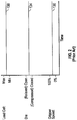
- FIG. 2 shows the simplest control scheme for the system 300. Three different graphs are shown versus time. The units in time can be any as part of the pultrusion process. As shown in Figure 2 , the grippers 309, 311, 313 are shown running at a consistent speed 130 somewhere between their 100% design speed and 0% speed (stopped). The die cavity gap 47 is shown between some maximum specification gap and some minimum specification gap 134. The load cell reading 138 is showing an effective internal pressure via a constant load cell reading. This is similar to thermoplastic tape pultrusions run consistently with thick parts (7.7 mm (0.303 inches) in thickness and 32 layers of Polystrand thermoplastic tape). In such a case, the die thickness that was machined was perfect. However, had it not been perfect, the frictional forces would have been too high or the consolidation would have been too low. In cases where the die is not perfectly set to the correct die cavity gap, then the system 300 and method of the present invention can correct such a problem.
- the grippers 309, 311, 313 are shown running at a consistent
- Figure 2 simulates setting the die cavity gap to the perfect thickness, as judged by numerous criteria, as if a solid die was perfectly manufactured.
- the system 300 of the present invention is critical in reducing the costs of manufacturing and trial and error in making the perfect die. Accordingly, Figure 2 represents a system that duplicates a perfect die cavity gap, and has an important other benefit. In start-up, it is necessary to open the cavity somewhat to make it easier to string-up the material at the start. Also, if splices ever are needed such as at the end of a pultrusion run, the pultrusion die system 300 can be slightly opened temporarily. If an anomaly occurs, the control system would catch the problem (such as the tape breaking at the inlet and suddenly having less volume). In this case, the load cell 8 on the die top 31 would catch a drop in consolidation pressures.
- Figure 3 shows a variation in software control that can be provided with the identical system described with respect to Figure 1 .
- the graph of Figure 3 is similar to Figure 2 .
- the term "pull-pression” is coined for the combination of pultrusion and compression (molding). It should be noted that two different moments in time are shown with the vertical lines 70 and 75.
- Line 70 in Figure 3 shows a point in time where the gripper 309, 311, 313 is pulling at 100% of design speed, indicated by 80. It is here where the die cavity gap 47 is most open or relaxed, as indicated by the peak in the curve 84. It so happens that the load cells 8 reading the die pressure will be at their lowest point 88.
- the cycle repeats itself.
- the material is in a relaxed condition and pulled into the pultrusion die system 300, then compressed at no speed, and then relaxed at 100% speed, and the process repeats itself.
- the pultrusion die system 300 starts out cold at the front (or partially heated below the melt point of the thermoplastic matrix).
- the material moves its way down the pultrusion die system 300, it encounters a hot zone designed to completely melt and consolidate the part under pressure, and then further down towards the die exit, the material is chilled or cooled and it is finished with its consolidation and eventually exits the cooled die as a finished section.
- Figure 4 is similar to Figure 3 . It should be noted that, in Figure 4 , there are peak load cell readings 99 associated with the most compressed die locations 95. Likewise, there are minimum load cell readings 98 that correspond to relaxed positions on the die gap 94. Shown in Figure 4 is a very high cyclic alternate actuation of servo controls to achieve this rapid movement and the numbers could amount to several per second, with the limitations of the actuation system and the ball screw travel. In this case, a small fraction of time allows the pultrusion speed to stay constant and follow steady pultrusion speed. Using the system 300 and method, trial and error can be used to determine the optimum control sequence.
- Figure 5 is similar to Figure 3 , except in Figure 5 the control interrupts a compression event 121 when some interference (e.g., a thicker core or skin material) has entered the pultrusion die system 300 and now the full compressed location 115 of the die cavity cannot be achieved as the load cell reading alarms the control system that maximum die pressure has occurred early in the compression cycle. In this case, the actuators will not complete the compression until the load has returned to an acceptable level.
- some interference e.g., a thicker core or skin material
- the lines 50 are break lines and indicate a much wider die than shown.
- a sample of an adjunct ball screw 206, load cell 208, and servo motor 204 are shown. This is shown inside a hole 214 which has been placed in the strongback, 2 and the plate 14.
- Figure 7 is a side elevation view similar to Figure 6 of an alternative example of a thermoplastic pultrusion die system and method, except that the CNC motors and actuators have been replaced with servo CNC hydraulic cylinders 705. Also shown is a sandwich panel in a compressed state, with skins 815 and core 810, in the compressed state as if the full design pressure had been applied through the cylinders 705.
- the servo-controlled hydraulic cylinders 705 can alternately close and open the die cavity.
- the die cavity can move to a position in which a given pressure is applied to the composite materials, which if, for example, a 0.69 Mpa (100 psi) pressure is required and if cylinder(s) 705 were incorporated into a centers-of-equal area, then 0.09 square meters (one square foot), or 929 square cm (144 square inches), requiring 0.69 Mpa (100 psi) would mean a 10.16 cm (4 inch) diameter cylinder 705 would operate at 7.9 Mpa (1146.5 psi) operating pressure.
- a single 10.16 cm (4 inch) cylinder 705 has 77.4 square cm (12.56 square inches) of area, and at 7.9 Mpa (1146.5 psi) will deliver 6531.7 kg (14400 lbs.), which is exactly 0.69 Mpa (100 psi) of laminate die pressure over 0.09 square meter (one square foot).
- the hydraulic cylinders 705 are intended to supply force at the centers-of-equal area.
- the strong-back 2 supports the upper platen 14, wherein the lower platen 814 has hydraulic cylinders 705 pressing on same and reacted by the ground 210.
- the die top 31 and die bottom 30 are shown in a compressed state, and as shown there is no need for bolts 45 to attach to the die upper and lower sections.
- FIG 8 is a side elevation view similar to Figure 7 of an alternative example of a thermoplastic pultrusion die system 900 and method.
- the view of thermoplastic pultrusion die system 900 in Figure 8 is of the exit of the die system 900, but a side view would show the same spherical shape (i.e., die system 900 has interior spherical curve in both longitudinal and lateral directions of die system 900, which manifests itself as an arc line when viewed, as in the case of Figure 8 at just one edge of the spherical die) and, thus, look similar to that shown in Figure 8 .
- the above description and drawings of the thermoplastic pultrusion die systems and methods with respect to Figures 1-7 are incorporated herein and like elements are shown with like reference numbers.
- thermoplastic pultrusion die system 900 and method are used to sequentially form from the input into the processing die of flat thermoplastic composite sandwich panel material into 100% spherical-curved sandwich panels 904 that exit the processing die, which are assembled together to form a rhombic triacontahedron composite radome 906 such as that shown in Figure 9 to protect a vast number of radar installations, including military radar.
- the flat sandwich panels include a foam core with top and bottom skins and as an option, 3-dimensional fibers transit from one skin to the other, through the foam.
- the thermoplastic pultrusion die system 900 and method are used to post mold sandwich panels for other applications, including panels of different spherical diameters and different cylindrical shapes, as well as complex curvatures.
- the thermoplastic pultrusion die system 900 includes a spherically curved die 910 in the shape of the defined spherical diameter of rhombic triacontahedron radome panels 906.
- the die 910 includes a die bottom 930 with a curved, spherical, concave top surface 935 and die top 940 with a curved, spherical, convex bottom surface 945.
- the curved, concave top surface 935 of the die bottom 930 and the curved, convex bottom surface 945 of the die top 940 form a curved spherical die cavity gap 947.
- the flat sandwich composite panels are processed into continuous curved, spherical sandwich composite panel parts 904.
- the curved sandwich composite panel parts 904 exiting the die system 900 climb according to the curvature being formed.
- the curved sandwich composite panel parts 904 are of the same length, size, and curvature and are assembled together to make the radome 906 to protect military radar.
- the convex and concave surfaces and die members are reversed, such that the spherical resultant panel exiting the die members curves in a downward direction.
- the rhombic triacontahedron composite radome 906 is a sandwich panel radome of the A-Sandwich variety wherein the thin skins on each side are a thermoplastic resin matrix with glass encapsulating a foam core, and the combination of the thin skins and the foam core are radio frequency (RF) transparent and sized to be approximately 1 ⁇ 4 the wavelength of the radar frequency of the military radar being protected.
- the radome 906 is made of spherical panels 904 and is of the order of 9.144 m to 18.288 m (30 feet to 60 feet) in diameter, but clearly could be any diameter from 1.524 m to 60.96 m (5 feet to 200 feet) in dimension.
- the radome 906 is a rhombic tricontrahedron radome, there is only one-sized panel to make the sphere. Because the radome 906 is a rhombic triacontahedron radome, there is only one-sized panel to make the sphere, excluding the truncated panels that attach to a mounting ring or foundation, at 908, and each said truncated panel is made from a larger, aforementioned one-sized panel.
- Hydrophobic films or coatings/paints can be applied to the outside of the radome sandwich part 904 prior to assembly to resist weathering and to keep the radome 906 clean and free of water droplets, in order to affect the superior transmission capability of the radar.
- the radome 906 is made of panels 904 having a few different configurations of a multitude of geodesic designs involving radome shapes, pentagons, hexagons, radome-shapes, oranger-peel shapes, and the like.
- Figure 11 is a block diagram illustrating an example computer system 550 that may be used in connection with various examples described herein.
- the computer system 550 may be used in conjunction with the computer system(s), computer(s), control(s), controller(s), control system (e.g., software, and/or hardware).
- control system e.g., software, and/or hardware
- other computer systems and/or architectures may be used, as will be clear to those skilled in the art.
- the computer system 550 preferably includes one or more processors, such as processor 552. Additional processors may be provided, such as an auxiliary processor to manage input/output, an auxiliary processor to perform floating point mathematical operations, a special-purpose microprocessor having an architecture suitable for fast execution of signal processing algorithms (e.g., digital signal processor), a slave processor subordinate to the main processing system (e.g., back-end processor), an additional microprocessor or controller for dual or multiple processor systems, or a coprocessor.
- auxiliary processors may be discrete processors or may be integrated with the processor 552.
- the processor 552 is preferably connected to a communication bus 554.
- the communication bus 554 may include a data channel for facilitating information transfer between storage and other peripheral components of the computer system 550.
- the communication bus 554 further may provide a set of signals used for communication with the processor 552, including a data bus, address bus, and control bus (not shown).
- the communication bus 554 may comprise any standard or non-standard bus architecture such as, for example, bus architectures compliant with industry standard architecture ("ISA”), extended industry standard architecture (“EISA”), Micro Channel Architecture (“MCA”), peripheral component interconnect (“PCI”) local bus, or standards promulgated by the Institute of Electrical and Electronics Engineers (“IEEE”) including IEEE 488 general-purpose interface bus (“GPIB”), IEEE 696/S-100, and the like.
- ISA industry standard architecture
- EISA extended industry standard architecture
- MCA Micro Channel Architecture
- PCI peripheral component interconnect
- IEEE Institute of Electrical and Electronics Engineers
- IEEE Institute of Electrical and Electronics Engineers
- GPIB general
- Computer system 550 preferably includes a main memory 556 and may also include a secondary memory 558.
- the main memory 556 provides storage of instructions and data for programs executing on the processor 552.
- the main memory 556 is typically semiconductor-based memory such as dynamic random access memory (“DRAM”) and/or static random access memory (“SRAM”).
- DRAM dynamic random access memory
- SRAM static random access memory
- Other semiconductor-based memory types include, for example, synchronous dynamic random access memory (“SDRAM”), Rambus dynamic random access memory (“RDRAM”), ferroelectric random access memory (“FRAM”), and the like, including read only memory (“ROM”).
- SDRAM synchronous dynamic random access memory
- RDRAM Rambus dynamic random access memory
- FRAM ferroelectric random access memory
- ROM read only memory
- the secondary memory 558 may optionally include a hard disk drive 560 and/or a removable storage drive 562, for example a floppy disk drive, a magnetic tape drive, a compact disc (“CD”) drive, a digital versatile disc (“DVD”) drive, etc.
- the removable storage drive 562 reads from and/or writes to a removable storage medium 564 in a well-known manner.
- Removable storage medium 564 may be, for example, a floppy disk, magnetic tape, CD, DVD, etc.
- the removable storage medium 564 is preferably a computer readable medium having stored thereon computer executable code (i.e., software) and/or data.
- the computer software or data stored on the removable storage medium 564 is read into the computer system 550 as electrical communication signals 578.
- secondary memory 558 may include other similar means for allowing computer programs or other data or instructions to be loaded into the computer system 550.
- Such means may include, for example, an external storage medium 572 and an interface 570.
- external storage medium 572 may include an external hard disk drive or an external optical drive, or and external magneto-optical drive.
- secondary memory 558 may include semiconductor-based memory such as programmable read-only memory (“PROM”), erasable programmable read-only memory (“EPROM”), electrically erasable read-only memory (“EEPROM”), or flash memory (block oriented memory similar to EEPROM). Also included are any other removable storage units 572 and interfaces 570, which allow software and data to be transferred from the removable storage unit 572 to the computer system 550.
- PROM programmable read-only memory
- EPROM erasable programmable read-only memory
- EEPROM electrically erasable read-only memory
- flash memory block oriented memory similar to EEPROM
- Computer system 550 may also include a communication interface 574.
- the communication interface 574 allows software and data to be transferred between computer system 550 and external devices (e.g. printers), networks, or information sources.
- external devices e.g. printers
- computer software or executable code may be transferred to computer system 550 from a network server via communication interface 574.
- Examples of communication interface 574 include a modem, a network interface card ("NIC"), a communications port, a PCMCIA slot and card, an infrared interface, and an IEEE 1394 fire-wire, just to name a few.
- Communication interface 574 preferably implements industry promulgated protocol standards, such as Ethernet IEEE 802 standards, Fiber Channel, digital subscriber line (“DSL”), asynchronous digital subscriber line (“ADSL”), frame relay, asynchronous transfer mode (“ATM”), integrated digital services network (“ISDN”), personal communications services (“PCS”), transmission control protocol/Internet protocol (“TCP/IP”), serial line Internet protocol/point to point protocol (“SLIP/PPP”), and so on, but may also implement customized or non-standard interface protocols as well.
- industry promulgated protocol standards such as Ethernet IEEE 802 standards, Fiber Channel, digital subscriber line (“DSL”), asynchronous digital subscriber line (“ADSL”), frame relay, asynchronous transfer mode (“ATM”), integrated digital services network (“ISDN”), personal communications services (“PCS”), transmission control protocol/Internet protocol (“TCP/IP”), serial line Internet protocol/point to point protocol (“SLIP/PPP”), and so on, but may also implement customized or non-standard interface protocols as well.
- Communication channel 576 carries signals 578 and can be implemented using a variety of wired or wireless communication means including wire or cable, fiber optics, conventional phone line, cellular phone link, wireless data communication link, radio frequency (RF) link, or infrared link, just to name a few.
- RF radio frequency
- Computer executable code i.e., computer programs or software
- main memory 556 and/or the secondary memory 558 are stored in the main memory 556 and/or the secondary memory 558.
- Computer programs can also be received via communication interface 574 and stored in the main memory 556 and/or the secondary memory 558.
- Such computer programs when executed, enable the computer system 550 to perform the various functions of the present invention as previously described.
- computer readable medium is used to refer to any media used to provide computer executable code (e.g., software and computer programs) to the computer system 550. Examples of these media include main memory 556, secondary memory 558 (including hard disk drive 560, removable storage medium 564, and external storage medium 572), and any peripheral device communicatively coupled with communication interface 574 (including a network information server or other network device). These computer readable mediums are means for providing executable code, programming instructions, and software to the computer system 550.
- the software may be stored on a computer readable medium and loaded into computer system 550 by way of removable storage drive 562, interface 570, or communication interface 574.
- the software is loaded into the computer system 550 in the form of electrical communication signals 578.
- the software when executed by the processor 552, preferably causes the processor 552 to perform the inventive features and functions previously described herein.
- ASICs application specific integrated circuits
- FPGAs field programmable gate arrays
- DSP digital signal processor
- a general-purpose processor can be a microprocessor, but in the alternative, the processor can be any processor, controller, microcontroller, or state machine.
- a processor can also be implemented as a combination of computing devices, for example, a combination of a DSP and a microprocessor, a plurality of microprocessors, one or more microprocessors in conjunction with a DSP core, or any other such configuration.
- a software module can reside in RAM memory, flash memory, ROM memory, EPROM memory, EEPROM memory, registers, hard disk, a removable disk, a CD-ROM, or any other form of storage medium including a network storage medium.
- An exemplary storage medium can be coupled to the processor such the processor can read information from, and write information to, the storage medium.
- the storage medium can be integral to the processor.
- the processor and the storage medium can also reside in an ASIC.
- thermoplastic pultrusion forming machine/apparatus and method With reference to FIGS. 12A-14 , an embodiment of a 3D thermoplastic pultrusion forming machine/apparatus and method will be described.
- Thermoplastic composite processing can be accomplished continuously by incrementally applying die pressure on preformed and prepreg material while the part is not moving through the machine, then sequentially altering between a release of the die surfaces/and movement-to-open-die-surfaces, then a movement in a controlled fashion an incremental step forward, followed again by zero line speed and a clamping force applied.
- Applicant has recognized that a need exists to manufacture a complex shape that has varying contours, such as a propeller for a small airplane. This is not a flat panel, a spherical panel or a pure cylindrical panel, and the shape of the propeller is a complex curvature surface that the state of the art would dictate a mold be produced and the material either vacuum bag-produced, or match mold produced, or the like. Applicant has also recognized that a need exists to produce a complex shape from the continuous system the Applicant has developed.
- thermoplastic pultrusion system and method includes a thermoplastic composite prepreg or the like that is sequentially consolidated at a "melt" temperature as the part is pulled forward, but, at the exit of the heated section of the die, as the chilled section is entered, the chilled section of the die is replaced with a new CNC actuated band that varies the lateral contour of the part as it exits the entire die.
- This very small and incremental die shape can be changed, both top and bottom, by computer code implemented by a computer system (e.g., computer system 550 shown in Figure 11 ) that commands actuators to change the shape of these chilled pressing bands, gradually and incrementally.
- thermoplastic pultrusion system and method allows any complex shape to be produced continuously without the need for expensive dies and net-shape-molds, in automotive industries it will be possible to continuously manufacture complex body panels such as doors and hoods; in the aerospace industry one can manufacture aircraft body panels, luggage compartments and airplane interior sections; and in the industrial markets, one can now manufacture any component that currently requires a large mold, including complex piping and duct-work.
- the 3D thermoplastic pultrusion system and method may include the system shown in Figure 1A , where heating occurs at the front section and chilling occurs at the rear section, but the 3D thermoplastic pultrusion system and method has only heating and adds a new component of CNC equipment, as shown in Figure 12A , that is placed and positioned just downstream of the heated die.
- the thermoplastic composite section has been thoroughly consolidated, worked and pressed, and is now ready to be chilled into a final shape. As the shape enters the device of Figure 12A , the following takes place:
- FIG 12A the 3D thermoplastic forming machine is shown.
- the upper chilled forming band 1040 and the lower chilled forming band 1042 are shown retracted from the thermoplastic prepreg material 1044.
- Both upper chilled forming band 1040 and the lower chilled forming band 1042 are flexible. That is, they are rigid, yet flexible and can curve depending on the force that is supplied by actuators 1020, 1021, 1022, 1023, 1024, and 1025.
- the commanded position comes from a computer and motion control program implemented by a computer system (e.g., computer system 550 shown in Figure 11 ) such that the servo motors 1010, 1011, 1012, 1013, 1014, and 1015 move the thrusting and retracting plates attached to the actuators and identified as 1050, 1051, 1052, 1053, 1054, and 1055.
- a computer system e.g., computer system 550 shown in Figure 11
- the servo motors 1010, 1011, 1012, 1013, 1014, and 1015 move the thrusting and retracting plates attached to the actuators and identified as 1050, 1051, 1052, 1053, 1054, and 1055.
- the upper chilling band 1040 has pivots 1060, 1061, and 1062 and the lower chilling band 1042 has pivots 1063, 1064, and 1065.
- a secondary pivot may be necessary that allows the actuators 1020, 1021, 1022, 1023, 1024, and 1025 to rotate. This accomplished by bearings, or the like shown as 1030, 1031, 1032, 1033, 1034, and 1035.
- the chilled bands are shown in the retracted position. Additionally the source for chilling the bands, whether fluid cooling and transfer or air flow, is not shown for clarity. But there are numerous systems available to constantly remove heat from the bands and maintain a chilled temperature (in thermoplastics a "chilled” temperature may be as high as 180 degrees F, which in thermoplastics technology is “chilled”).
- Figure 12B shows the bands 1040 and 1042 having been retracted, but note the thermoplastic prepreg material is now in a somewhat arched shape as defined by the CNC program. Note the pivots of 1060 and 1062 have rotated, as have the pivots 1063 and 1065. Additionally the actuator bearings show a rotation of the actuators at 1030 and 1032 as well as 1033 and 1035. The central actuators, 1021 and 1024 have not pivoted as they remain in a position that is midway on the arc of the material.
- FIG. 12B Shown in Figure 12B is the arch of the prepreg composite identified as 1046. The significance of this can be realized when looking at Figure 13 . Note that the straight section of thermoplastic composite 1044 in Figure 12A is shown as 1044 in Figure 13 , and the curved thermoplastic composite 1046 in Figure 12B is shown as 1046 in Figure 13 .
- the instantaneous chilling by the chilled bands defines the surface contour in the Y-direction (along the band and 90 degrees to the pultrusion direction)
- varying contours occur in the X-direction, or the pultrusion direction, by changing the CNC code for each incremental pulling in the pultrusion direction; the varying surface contour is in both directions, making a "compound" shape.
- an inside and outside shape can be defined and the chilled bands can take the shape and additionally pressure can be applied from the actuators such that the composite material is cooled and consolidated between the upper and lower bands.
- a part is actually a sandwich panel that is being formed and the contour shown in Figure 13 is an aerodynamic surface that is the pressure side of a public domain airfoil, the NACA series 65 airfoil, which has been, over the years, thoroughly defined and thoroughly tested.
- the NACA series 65 airfoil which has been, over the years, thoroughly defined and thoroughly tested.
- there is a core and two skins that form the sandwich panel that is being dynamically shaped there is a core and two skins that form the sandwich panel that is being dynamically shaped.
- Applicant's 3D fiber technology shown in Figure 15 wherein 3D fibers tie the core to the skins may be used for this aerodynamic surface of Figure 13 .
- the surface is a structural sandwich panel or fiber composite material wall.
- Each wall includes a first sandwich skin 131, a second sandwich skin 133, interior foam core 135, and distinct groups 137 of 3D Z-axis fibers that extend from the first sandwich skin 131 to the second sandwich skin 133, linking the sandwich skins 131, 135 together.
- the heated die shown and described with respect to FIGS. 1-8 is a variable curvature die, operating in a similar fashion to the chilled bands 1040 and 1042.
- thermoplastic pultrusion system and method is significantly important to US industry. Automotive doors can be made in rapid fashion and tooling can be minimized.
- aircraft industry one can now make propellers from thermoplastic composite, by simply programming a machine. Note that Figure 14 shows a thermoplastic composite that is not only curved but has a twist. Once formed the propeller could be machined along 1110, shown in Figure 14 , and with very little post processing, be completed into a finished composite propeller. Note that this can be accomplished with no molds.
- the example computer system 550 shown and described with respect to Figure 11 provides the computer control described here for the 3D thermoplastic pultrusion system and method.
Description
- The present invention relates to 3D pultrusion systems and methods.
- In recent times, advances have been made in thermoplastic 3D printing using CNC technology and 3-axis positioning. These 3D printing machines allow a wide variety of shapes to be produced with nothing more than a CAD drawing. That is, they have the advantage of creating a complex shape without a mold.
- Document
US8747098 discloses a 3D thermoplastic pultrusion system,characterized by a heating mechanism, a heated thermoplastic pultrusion die system, and a 3D thermoplastic forming machines downstream of the heated thermoplastic pultrusion die system. - It is an object of the invention to create a 3D pultrusion system and method based upon a 3D/variable die system to continuously produce thermoplastic composite pultrusions with at least one of varying cross-section geometry and constant surface contours, varying cross-section geometry and varying surface contours, and constant cross-section geometry and varying surface contours. This and other objects are achieved by the system according to
claim 1 and the method according to claim 12. Advantageous further embodiments are claimed in the dependent claims. - The 3D pultrusion system and method enables a myriad of industries, from automotive, industrial, and aerospace to create continuous, automated complex shapes using only CAD programs and CNC processing without the need for expensive molds.
- The accompanying drawings illustrating examples and illustrating embodiments of the invention serve together with the description to explain the principles of the invention.
-
Figure 1A is a diagram that demonstrates an exemplary thermoplastic composite tape pultrusion process in which the thermoplastic pultrusion die system and method of the present invention may be incorporated into in one application. -
Figure 1B is a side elevation view of an example showing an end of a die and die cavity gap (end being defined as the exit of the die as one would view the die system from the position of the pultrusion grippers) of an example of the thermoplastic pultrusion die system and method. -
Figure 2 is a graph showing how the example of the thermoplastic pultrusion die system and method shown inFigure 1B can operate steady state at some predefined load cell reading, which is a closed loop control and feedback on the opening of the die cavity gap, and synchronized with the pultrusion speed. -
Figure 3 is a graph similar toFigure 2 in which a further example is possible with the thermoplastic pultrusion die system and method. In this example, the thermoplastic pultrusion die system and method allow for temporary halting of the gripper speed while high-compression forces are temporarily applied to the part. -
Figure 4 is a graph similar toFigure 3 , except that in this example of the thermoplastic pultrusion die system and method a rapid servo control and high frequency of the change in die cavity gap occurs in a manner that does not require the grippers to be stopped. -
Figure 5 is a graph similar toFigure 3 , and shows how the thermoplastic pultrusion die system and method could react to an anomaly such as a splice, a knot in a wood core, or other disruption causing excessive die pressures. -
Figure 6 is a side elevation view similar toFigure 1B of an alternative example of a thermoplastic pultrusion die system and method with multiple CNC type servo actuators and load cells installed over a very wide die top, a very wide plate, and a very wide strongback. -
Figure 7 is a side elevation view similar toFigure 6 of an alternative example of a thermoplastic pultrusion die system and method, except that the CNC motors and actuators have been replaced with servo CNC hydraulic cylinders and a sandwich panel is shown. -
Figure 8 is a side elevation view similar toFigure 7 of a further example of a thermoplastic pultrusion die system and method, except that the interior of the die is spherically curved. -
Figure 9 is a perspective view of an example of a rhombic triacontahedron composite radome. -
Figures 10A-10E are perspective views of different stages of spherical thermoplastic composite sandwich panels processed in a small spherical die similar to that as shown inFigure 8 and exiting the die along the defined spherical path into curved spherical composite sandwich panels using the thermoplastic pultrusion die system ofFigure 8 . -
Figure 11 is a block diagram illustrating an example computer system that may be used in connection with various examples described herein. -
Figure 12A shows an embodiment of the invention of a 3D thermoplastic forming machine. -
Figure 12B shows the 3D thermoplastic forming machine ofFigure 12A with bands retracted and the thermoplastic prepreg material shown in a somewhat arched shape. -
Figure 13 shows a section of a thermoplastic composite resulting from the 3D thermoplastic composite pultrusion system and method according to an embodiment of the invention. -
Figure 14 shows a section of another thermoplastic composite resulting from the 3D thermoplastic composite pultrusion system and method according to an embodiment of the invention where the thermoplastic composite is not only curved but also has a twist. -
Figure 15 shows a cross-sectional view of an example of a structural sandwich panel or fiber composite material wall of a surface or part produced by a method described herein. - With reference to
Figures 1-8 , before describing examples of a 3D thermoplastic pultrusion forming machine/apparatus and method, an example of a thermoplastic pultrusion die system ("system") 300 and method of processing using the same will first be described. The 3D thermoplastic pultrusion forming machine/apparatus and method is an improvement on thesystem 300 and method. - With reference to
Figure 1A , before describing thesystem 300, an example of an exemplary thermoplastic composite tapepultrusion processing assembly 310 and method that the thermoplastic pultrusion diesystem 300 and method may be a part of will first be described. - In the thermoplastic composite tape
pultrusion processing assembly 310, the pultrusion process moves from left to right. From left-to-right, theassembly 310 includes atunnel oven 315, the thermoplasticpultrusion die system 300, and a pultrusion gripper mechanism including one or more grippers (e.g., one, two, three) 309, 311, 313 in series. InFigure 1A , a fairly short thermoplasticpultrusion die system 300 is shown, but in actuality the thermoplasticpultrusion die system 300 may extend forward in theprocess 6 meter (20 feet) or more to assist with heating of multiple tapes or plies of thermoplastic tape to achieve faster line speeds on the processing. - The one or
more grippers solid part 302 from the thermoplasticpultrusion die system 300 by clamping and pulling in a handover-hand method, using either a combination of one, two or three grippers at a time. In an alternative example, a mechanical motive transmitter other than one or more grippers is used such as, but not by way of limitation, nip rollers or a caterpillar dive system. -
Raw material 304 includes a composite material including one or more thermoplastic composite tapes entering the thermoplasticpultrusion die system 300. Beforeraw material 304 enters the thermoplasticpultrusion die system 300, upstream of the thermoplasticpultrusion die system 300, the thermoplastic composite tapes are preheated in a pre-heating mechanism (e.g., tunnel oven) 315, which can be heated to a temperature just below a melt temperature of the thermoplastic resin of the thermoplastic composite tapes. - As the pultruded tape material exits the thermoplastic
pultrusion die system 300, it is chilled and consolidated, as represented by thesolid part 302. The transition from a series of individual thermoplastic composite tapes to thesolid part 302 takes place in the thermoplasticpultrusion die system 300. - The thermoplastic
pultrusion die system 300 preferably includes a heating mechanism (e.g., heater or hot zone) in the front of the thermoplasticpultrusion die system 300 heated byplatens 330 using a series of heaters andcontrollers 335. At an end of thermoplasticpultrusion die system 300, just before the pultruded tape material exits, is a cooling mechanism (e.g., cooler or chilling zone) provided bychilling platens 340, which are physically attached to thermoplasticpultrusion die system 300. Theplatens 340 have acooling water circuit 342 designed to carry cooling fluids such as water to a radiating system, shown here with afan 345. In alternative examples, alternative heating mechanisms and/or cooling mechanism may be used with the thermoplasticpultrusion die system 300. Acomputer system 338 controls one of more of the components of theassembly 310. - With reference to
Figure 1B , the thermoplasticpultrusion die system 300 is a die, platen, and frame arrangement. The thermoplasticpultrusion die system 300 is shown in elevation inFigure 1B as if viewing from thepultrusion grippers pultrusion die system 300. - The thermoplastic pultrusion die
system 300 includes a die bottom 30 (supported by a lower support 18) and a dietop 31 separated by adie cavity gap 47. The dietop 31 is bolted to the diebottom 30 atbolt holes 45. Along opposite edges of thedie bottom 30 and dietop 31 are elongated, narrowflat silicone seals 40.Load cells 8 are supposed by thelower support 18 are measure the load pressure at various locations in the thermoplasticpultrusion die system 300. Theload cells 8 are operably coupled toCNC servo motors 4 viaball screws 6. Astrongback 2 and aplaten 14 move with rotation of the ball screws (and are associated with thedie top 31 and/or die bottom 30) to increase or decrease thedie cavity gap 47. -
Figure 1B shows the assembly of the die halves with thesilicone seal 40 and theball screws 6 withservo motors 4 andload cells 8, as one would view thesystem 300 prior to connecting thedie top 31 to thesilicone seal 40 and prior to actuating theplaten 14 and thestrongback 2 into intimate contact with thedie top 31. -
Figure 1B illustrates the diecavity gap 47 at an exit end of the thermoplastic pultrusion diesystem 300. Once thedie top 31 is bolted to thedie bottom 30 at thebolt holes 45 shown on each the left and right hand sides of the die, then thedie cavity gap 47 will be a closed cavity, but for the opening at the entrance of the die (not shown) and the opening at the exit (shown as 47 inFigure 1B ). - An important aspect of the
system 300 is the two pieces of silicone seal material shown as 40 on both sides of thesystem 300. Although thesilicone seals 40 are shown as narrow, elongated strips of silicone material, in alternative examples, thesilicone seals 40 may be any shape/configuration. For example, but not by way of limitation, thesilicone seals 40 may be round and fit into somewhat circular slots of matting flanges of bothdie bottom 30 and dietop 31. The bolts holding the diebottom 30 and the dietop 31 together would pinch thesilicone seal 40. In the example shown, a thread is disposed in diebottom 30 and a slip fit in dietop 31. The bolts can be tightened to give a maximum die cavity gap position and no more. The minimum die cavity position is attained by actuating theplaten 14, which is shown raised above thedie top 31, but would be brought down into intimate contact by way of the actuatedball screws 6 that are shown on each side of the thermoplasticpultrusion die system 300. Although only twoball screws 6 are shown inFigure 1B , the thermoplasticpultrusion die system 300 may include 4 or more actuatedball screws 6. - The
platen 14 is attached to the bottom of thestrongback 2, which allows for a steady and well distributed downward force on the top of the thermoplasticpultrusion die system 300 when theball screws 6 are actuated downward by theservo motors 4. Theservo motors 4 are controlled by a CNC control system that command(s) a given position through sophisticated motion control including, but not limited to, commanded acceleration, deceleration, and soft reversal of torque and direction. When the downward force of theplaten 14 depresses the silicone seals 40, there is additional resistance of the thermoplastic tape material, which is not shown inFigure 1B for clarity, but would be in the entiredie cavity gap 47. Since the silicone seals 40 are designed for high temperature and have good recovery after compression, thedie cavity gap 47 remains sealed on the sides through the entire actuation cycle from maximum gap to minimum gap. The silicone seals 40 can stretch or be compressed up to 800% without losing its/their elasticity. - Although the maximum
die cavity gap 47 can be set by the bolts (in bolt holds 45), a more preferred method is the use of theload cells 8 at the end ofball screws 6 to give a measure of calibrated die pressure. If the weight of thedie top 31 is great, it may be necessary in some cases to attach the die top 31 to theplaten 14 and thestrongback 2. In this way, absolute minimum material pressure can be achieved when the ball screws 6 are actuated upward. The goal will be to adjust thedie cavity gap 47 to the proper height to achieve continuous pultrusion of thermoplastic composite laminates, and when the situation calls for it, thesystem 300 can actively alternate between pultrusion and cycling thedie cavity gap 47, as well be described in more detail below. - Although the
lower support 18 is shown as being fixed and secured to ground/not deflectable, in one or more alternative examples, thesupport 18 is similar to theplaten 14 and thestrongback 2. Thus, in one or more examples, thesystem 300 may include an upper movable die top/platen/strongback and/or a lower movable die top/platen/strongback. - Purposely not shown in
Figure 1B are the heating and cooling systems (they can generally be seen inFigure 1A ), which include a heating zone in the center and generally forward sections of thesystem 300, top and bottom, and with a cooling section toward the rear, or discharge end of the die, both top and bottom. Multiple coordinated controls may be used to control thesystem 300. If, for example, thesystem 300 ofFigure 1B had fourball screws 6 with fourservo motors 4, thesystem 300 would include 4-axes of motion control. With the addition of three pultrusion grippers (SeeFigure 1A ), thesystem 300 would include a minimum of a 7-axis CNC system and process. The computer hardware and/or software to interface with thissystem 300 will be generally described below with respect to theexemplary computer system 550 described below with respect toFigure 11 . - Once the example of
Figure 1A is provided as asystem 300, with the CNC motion control, then the control schemes ofFigures 2 ,3 ,4 , and5 can be implemented. There are reasons to consider each, which will depend on factors, such as, but not limited to, laminate thickness, laminate density, surface finish required, addition of foreign material (besides thermoplastic tape) including the wide variety of core materials such as, but not limited to, wood, concrete, gypsum, honeycomb, foam, and other foreign materials/cores that can be found in sandwich panel construction. -
Figure 2 shows the simplest control scheme for thesystem 300. Three different graphs are shown versus time. The units in time can be any as part of the pultrusion process. As shown inFigure 2 , thegrippers consistent speed 130 somewhere between their 100% design speed and 0% speed (stopped). Thedie cavity gap 47 is shown between some maximum specification gap and someminimum specification gap 134. The load cell reading 138 is showing an effective internal pressure via a constant load cell reading. This is similar to thermoplastic tape pultrusions run consistently with thick parts (7.7 mm (0.303 inches) in thickness and 32 layers of Polystrand thermoplastic tape). In such a case, the die thickness that was machined was perfect. However, had it not been perfect, the frictional forces would have been too high or the consolidation would have been too low. In cases where the die is not perfectly set to the correct die cavity gap, then thesystem 300 and method of the present invention can correct such a problem. - In the case of thin laminates, the adjustment of die cavity gap may be mandatory in achieving a perfect pultrusion.
Figure 2 simulates setting the die cavity gap to the perfect thickness, as judged by numerous criteria, as if a solid die was perfectly manufactured. Thesystem 300 of the present invention is critical in reducing the costs of manufacturing and trial and error in making the perfect die. Accordingly,Figure 2 represents a system that duplicates a perfect die cavity gap, and has an important other benefit. In start-up, it is necessary to open the cavity somewhat to make it easier to string-up the material at the start. Also, if splices ever are needed such as at the end of a pultrusion run, thepultrusion die system 300 can be slightly opened temporarily. If an anomaly occurs, the control system would catch the problem (such as the tape breaking at the inlet and suddenly having less volume). In this case, theload cell 8 on thedie top 31 would catch a drop in consolidation pressures. -
Figure 3 shows a variation in software control that can be provided with the identical system described with respect toFigure 1 . With thin laminates, it is sometimes necessary to prevent the sloughing of off-axis tapes, such as +/- 30 degrees, +/- 45 degrees, or 90 degrees. This sloughing is caused by tight die cavity gaps, minimum material and high frictional forces. The graph ofFigure 3 is similar toFigure 2 . The term "pull-pression" is coined for the combination of pultrusion and compression (molding). It should be noted that two different moments in time are shown with thevertical lines -
Line 70 inFigure 3 shows a point in time where thegripper die cavity gap 47 is most open or relaxed, as indicated by the peak in thecurve 84. It so happens that theload cells 8 reading the die pressure will be at theirlowest point 88. - As the
grippers raw material 304 is being pulled into the entrance of thepultrusion die system 300 and the finishedcomposite part 302 is being pulled from the exit of thepultrusion die system 300. After a discrete unit of time, thegrippers die top 31 and the part is effectively undergoing compression. At this point, thegrippers % speed 81 and the die cavity is compressed atcycle point 85 and the load cell(s) 8 indicatemaximum compression 89. - It is at this point that the cycle repeats itself. At intervals, the material is in a relaxed condition and pulled into the
pultrusion die system 300, then compressed at no speed, and then relaxed at 100% speed, and the process repeats itself. Thepultrusion die system 300 starts out cold at the front (or partially heated below the melt point of the thermoplastic matrix). As the material moves its way down thepultrusion die system 300, it encounters a hot zone designed to completely melt and consolidate the part under pressure, and then further down towards the die exit, the material is chilled or cooled and it is finished with its consolidation and eventually exits the cooled die as a finished section. -
Figure 4 is similar toFigure 3 . It should be noted that, inFigure 4 , there are peakload cell readings 99 associated with the mostcompressed die locations 95. Likewise, there are minimumload cell readings 98 that correspond to relaxed positions on thedie gap 94. Shown inFigure 4 is a very high cyclic alternate actuation of servo controls to achieve this rapid movement and the numbers could amount to several per second, with the limitations of the actuation system and the ball screw travel. In this case, a small fraction of time allows the pultrusion speed to stay constant and follow steady pultrusion speed. Using thesystem 300 and method, trial and error can be used to determine the optimum control sequence. -
Figure 5 is similar toFigure 3 , except inFigure 5 the control interrupts acompression event 121 when some interference (e.g., a thicker core or skin material) has entered thepultrusion die system 300 and now the fullcompressed location 115 of the die cavity cannot be achieved as the load cell reading alarms the control system that maximum die pressure has occurred early in the compression cycle. In this case, the actuators will not complete the compression until the load has returned to an acceptable level. - In many large pultrusion die systems, producing panels continuously and up to as much as 4.27 meter (14 feet) in width, it is difficult to pressure the material and keep the die surfaces at the same gap in the middle of the
pultrusion die system 300 as the edges. In this case, as shown inFigure 6 , thelines 50 are break lines and indicate a much wider die than shown. A sample of anadjunct ball screw 206,load cell 208, andservo motor 204 are shown. This is shown inside ahole 214 which has been placed in the strongback, 2 and theplate 14. For a very widepultrusion die system 300, there may be several of these placed every 0.3, 0.61, 0.91 or 1.22 meter (1, 2, 3, or 4 feet) (or other distance) apart across the width of thepultrusion die system 300 and these are there to achieve the same purpose aselements Figure 6 . These multiple actuators could allow for controlling die cavity gaps in the center of a wide, flat die, in which any pressure would want to slightly open up the gap, due to hoop stress forces. There is a need for active CNC control of thedie cavity gap 47 over the entire panel width, and this will be especially important in thin and wide thermoplastic composites manufactured from the tapes described herein. -
Figure 7 is a side elevation view similar toFigure 6 of an alternative example of a thermoplastic pultrusion die system and method, except that the CNC motors and actuators have been replaced with servo CNChydraulic cylinders 705. Also shown is a sandwich panel in a compressed state, withskins 815 andcore 810, in the compressed state as if the full design pressure had been applied through thecylinders 705. - The servo-controlled
hydraulic cylinders 705 can alternately close and open the die cavity. When closing, the die cavity can move to a position in which a given pressure is applied to the composite materials, which if, for example, a 0.69 Mpa (100 psi) pressure is required and if cylinder(s) 705 were incorporated into a centers-of-equal area, then 0.09 square meters (one square foot), or 929 square cm (144 square inches), requiring 0.69 Mpa (100 psi) would mean a 10.16 cm (4 inch)diameter cylinder 705 would operate at 7.9 Mpa (1146.5 psi) operating pressure. In other words, a single 10.16 cm (4 inch)cylinder 705 has 77.4 square cm (12.56 square inches) of area, and at 7.9 Mpa (1146.5 psi) will deliver 6531.7 kg (14400 lbs.), which is exactly 0.69 Mpa (100 psi) of laminate die pressure over 0.09 square meter (one square foot). Further toFigure 7 , thehydraulic cylinders 705 are intended to supply force at the centers-of-equal area. As indicated above, the strong-back 2 supports theupper platen 14, wherein thelower platen 814 hashydraulic cylinders 705 pressing on same and reacted by theground 210. Thedie top 31 and die bottom 30 are shown in a compressed state, and as shown there is no need forbolts 45 to attach to the die upper and lower sections. -
Figure 8 is a side elevation view similar toFigure 7 of an alternative example of a thermoplasticpultrusion die system 900 and method. The view of thermoplasticpultrusion die system 900 inFigure 8 is of the exit of thedie system 900, but a side view would show the same spherical shape (i.e., diesystem 900 has interior spherical curve in both longitudinal and lateral directions ofdie system 900, which manifests itself as an arc line when viewed, as in the case ofFigure 8 at just one edge of the spherical die) and, thus, look similar to that shown inFigure 8 . The above description and drawings of the thermoplastic pultrusion die systems and methods with respect toFigures 1-7 are incorporated herein and like elements are shown with like reference numbers. - In the example shown, the thermoplastic
pultrusion die system 900 and method are used to sequentially form from the input into the processing die of flat thermoplastic composite sandwich panel material into 100% spherical-curved sandwich panels 904 that exit the processing die, which are assembled together to form a rhombictriacontahedron composite radome 906 such as that shown inFigure 9 to protect a vast number of radar installations, including military radar. The flat sandwich panels include a foam core with top and bottom skins and as an option, 3-dimensional fibers transit from one skin to the other, through the foam. In alternative examples or implementations, the thermoplasticpultrusion die system 900 and method are used to post mold sandwich panels for other applications, including panels of different spherical diameters and different cylindrical shapes, as well as complex curvatures. - The thermoplastic
pultrusion die system 900 includes a sphericallycurved die 910 in the shape of the defined spherical diameter of rhombictriacontahedron radome panels 906. Thedie 910 includes adie bottom 930 with a curved, spherical, concavetop surface 935 and die top 940 with a curved, spherical,convex bottom surface 945. Together, the curved, concavetop surface 935 of thedie bottom 930 and the curved,convex bottom surface 945 of thedie top 940 form a curved sphericaldie cavity gap 947. - As shown in
Figures 10A-10D , during the efficient in-line thermoplastic pultrusion method, the flat sandwich composite panels are processed into continuous curved, spherical sandwichcomposite panel parts 904. The curved sandwichcomposite panel parts 904 exiting thedie system 900 climb according to the curvature being formed. In the example shown, the curved sandwichcomposite panel parts 904 are of the same length, size, and curvature and are assembled together to make theradome 906 to protect military radar. In alternative examples, it may be desirable to make curved configurations/structures where one of more of the curved panels have a different curvature, length, and/or size. In a still further example, the convex and concave surfaces and die members are reversed, such that the spherical resultant panel exiting the die members curves in a downward direction. - With reference to
Figure 9 , the rhombictriacontahedron composite radome 906 is a sandwich panel radome of the A-Sandwich variety wherein the thin skins on each side are a thermoplastic resin matrix with glass encapsulating a foam core, and the combination of the thin skins and the foam core are radio frequency (RF) transparent and sized to be approximately ¼ the wavelength of the radar frequency of the military radar being protected. Theradome 906 is made ofspherical panels 904 and is of the order of 9.144 m to 18.288 m (30 feet to 60 feet) in diameter, but clearly could be any diameter from 1.524 m to 60.96 m (5 feet to 200 feet) in dimension. Because theradome 906 is a rhombic tricontrahedron radome, there is only one-sized panel to make the sphere. Because theradome 906 is a rhombic triacontahedron radome, there is only one-sized panel to make the sphere, excluding the truncated panels that attach to a mounting ring or foundation, at 908, and each said truncated panel is made from a larger, aforementioned one-sized panel. - Hydrophobic films or coatings/paints can be applied to the outside of the
radome sandwich part 904 prior to assembly to resist weathering and to keep theradome 906 clean and free of water droplets, in order to affect the superior transmission capability of the radar. - To house the
radome 906, there is a truncation of the dome, at approximately 85% of the height/diameter of theradome 906, where a mountingring 908 is located and theradome 906 bolts, or is fastened, to the mountingring 908 for structural stiffness and rigidity, and here there is a set of different shaped panels, but each formed from the same base-singular panel 904, to create thespherical radome 906. In an alternative example, theradome 906 is made ofpanels 904 having a few different configurations of a multitude of geodesic designs involving radome shapes, pentagons, hexagons, radome-shapes, oranger-peel shapes, and the like. -
Figure 11 is a block diagram illustrating anexample computer system 550 that may be used in connection with various examples described herein. For example, thecomputer system 550 may be used in conjunction with the computer system(s), computer(s), control(s), controller(s), control system (e.g., software, and/or hardware). However, other computer systems and/or architectures may be used, as will be clear to those skilled in the art. - The
computer system 550 preferably includes one or more processors, such asprocessor 552. Additional processors may be provided, such as an auxiliary processor to manage input/output, an auxiliary processor to perform floating point mathematical operations, a special-purpose microprocessor having an architecture suitable for fast execution of signal processing algorithms (e.g., digital signal processor), a slave processor subordinate to the main processing system (e.g., back-end processor), an additional microprocessor or controller for dual or multiple processor systems, or a coprocessor. Such auxiliary processors may be discrete processors or may be integrated with theprocessor 552. - The
processor 552 is preferably connected to acommunication bus 554. Thecommunication bus 554 may include a data channel for facilitating information transfer between storage and other peripheral components of thecomputer system 550. Thecommunication bus 554 further may provide a set of signals used for communication with theprocessor 552, including a data bus, address bus, and control bus (not shown). Thecommunication bus 554 may comprise any standard or non-standard bus architecture such as, for example, bus architectures compliant with industry standard architecture ("ISA"), extended industry standard architecture ("EISA"), Micro Channel Architecture ("MCA"), peripheral component interconnect ("PCI") local bus, or standards promulgated by the Institute of Electrical and Electronics Engineers ("IEEE") including IEEE 488 general-purpose interface bus ("GPIB"), IEEE 696/S-100, and the like. -
Computer system 550 preferably includes amain memory 556 and may also include asecondary memory 558. Themain memory 556 provides storage of instructions and data for programs executing on theprocessor 552. Themain memory 556 is typically semiconductor-based memory such as dynamic random access memory ("DRAM") and/or static random access memory ("SRAM"). Other semiconductor-based memory types include, for example, synchronous dynamic random access memory ("SDRAM"), Rambus dynamic random access memory ("RDRAM"), ferroelectric random access memory ("FRAM"), and the like, including read only memory ("ROM"). - The
secondary memory 558 may optionally include ahard disk drive 560 and/or aremovable storage drive 562, for example a floppy disk drive, a magnetic tape drive, a compact disc ("CD") drive, a digital versatile disc ("DVD") drive, etc. Theremovable storage drive 562 reads from and/or writes to aremovable storage medium 564 in a well-known manner.Removable storage medium 564 may be, for example, a floppy disk, magnetic tape, CD, DVD, etc. - The
removable storage medium 564 is preferably a computer readable medium having stored thereon computer executable code (i.e., software) and/or data. The computer software or data stored on theremovable storage medium 564 is read into thecomputer system 550 as electrical communication signals 578. - In alternative examples,
secondary memory 558 may include other similar means for allowing computer programs or other data or instructions to be loaded into thecomputer system 550. Such means may include, for example, anexternal storage medium 572 and aninterface 570. Examples ofexternal storage medium 572 may include an external hard disk drive or an external optical drive, or and external magneto-optical drive. - Other examples of
secondary memory 558 may include semiconductor-based memory such as programmable read-only memory ("PROM"), erasable programmable read-only memory ("EPROM"), electrically erasable read-only memory ("EEPROM"), or flash memory (block oriented memory similar to EEPROM). Also included are any otherremovable storage units 572 andinterfaces 570, which allow software and data to be transferred from theremovable storage unit 572 to thecomputer system 550. -
Computer system 550 may also include acommunication interface 574. Thecommunication interface 574 allows software and data to be transferred betweencomputer system 550 and external devices (e.g. printers), networks, or information sources. For example, computer software or executable code may be transferred tocomputer system 550 from a network server viacommunication interface 574. Examples ofcommunication interface 574 include a modem, a network interface card ("NIC"), a communications port, a PCMCIA slot and card, an infrared interface, and an IEEE 1394 fire-wire, just to name a few. -
Communication interface 574 preferably implements industry promulgated protocol standards, such as Ethernet IEEE 802 standards, Fiber Channel, digital subscriber line ("DSL"), asynchronous digital subscriber line ("ADSL"), frame relay, asynchronous transfer mode ("ATM"), integrated digital services network ("ISDN"), personal communications services ("PCS"), transmission control protocol/Internet protocol ("TCP/IP"), serial line Internet protocol/point to point protocol ("SLIP/PPP"), and so on, but may also implement customized or non-standard interface protocols as well. - Software and data transferred via
communication interface 574 are generally in the form of electrical communication signals 578. Thesesignals 578 are preferably provided tocommunication interface 574 via acommunication channel 576.Communication channel 576 carriessignals 578 and can be implemented using a variety of wired or wireless communication means including wire or cable, fiber optics, conventional phone line, cellular phone link, wireless data communication link, radio frequency (RF) link, or infrared link, just to name a few. - Computer executable code (i.e., computer programs or software) is stored in the
main memory 556 and/or thesecondary memory 558. Computer programs can also be received viacommunication interface 574 and stored in themain memory 556 and/or thesecondary memory 558. Such computer programs, when executed, enable thecomputer system 550 to perform the various functions of the present invention as previously described. - In this description, the term "computer readable medium" is used to refer to any media used to provide computer executable code (e.g., software and computer programs) to the
computer system 550. Examples of these media includemain memory 556, secondary memory 558 (includinghard disk drive 560,removable storage medium 564, and external storage medium 572), and any peripheral device communicatively coupled with communication interface 574 (including a network information server or other network device). These computer readable mediums are means for providing executable code, programming instructions, and software to thecomputer system 550. - In an example that is implemented using software, the software may be stored on a computer readable medium and loaded into
computer system 550 by way ofremovable storage drive 562,interface 570, orcommunication interface 574. In such an example, the software is loaded into thecomputer system 550 in the form of electrical communication signals 578. The software, when executed by theprocessor 552, preferably causes theprocessor 552 to perform the inventive features and functions previously described herein. - Various examples may also be implemented primarily in hardware using, for example, components such as application specific integrated circuits ("ASICs"), or field programmable gate arrays ("FPGAs"). Implementation of a hardware state machine capable of performing the functions described herein will also be apparent to those skilled in the relevant art. Various examples may also be implemented using a combination of both hardware and software.
- Furthermore, those of skill in the art will appreciate that the various illustrative logical blocks, modules, circuits, and method steps described in connection with the above described figures and the examples disclosed herein can often be implemented as electronic hardware, computer software, or combinations of both. To clearly illustrate this interchangeability of hardware and software, various illustrative components, blocks, modules, circuits, and steps have been described above generally in terms of their functionality. Whether such functionality is implemented as hardware or software depends upon the particular application and design constraints imposed on the overall system. Skilled persons can implement the described functionality in varying ways for each particular application, but such implementation decisions should not be interpreted as causing a departure from the scope of the invention. In addition, the grouping of functions within a module, block, circuit or step is for ease of description. Specific functions or steps can be moved from one module, block or circuit to another without departing from the invention.
- Moreover, the various illustrative logical blocks, modules, and methods described in connection with the examples disclosed herein can be implemented or performed with a general purpose processor, a digital signal processor ("DSP"), an ASIC, FPGA or other programmable logic device, discrete gate or transistor logic, discrete hardware components, or any combination thereof designed to perform the functions described herein. A general-purpose processor can be a microprocessor, but in the alternative, the processor can be any processor, controller, microcontroller, or state machine. A processor can also be implemented as a combination of computing devices, for example, a combination of a DSP and a microprocessor, a plurality of microprocessors, one or more microprocessors in conjunction with a DSP core, or any other such configuration.
- Additionally, the steps of a method or algorithm described in connection with the examples disclosed herein can be embodied directly in hardware, in a software module executed by a processor, or in a combination of the two. A software module can reside in RAM memory, flash memory, ROM memory, EPROM memory, EEPROM memory, registers, hard disk, a removable disk, a CD-ROM, or any other form of storage medium including a network storage medium. An exemplary storage medium can be coupled to the processor such the processor can read information from, and write information to, the storage medium. In the alternative, the storage medium can be integral to the processor. The processor and the storage medium can also reside in an ASIC.
- With reference to
FIGS. 12A-14 , an embodiment of a 3D thermoplastic pultrusion forming machine/apparatus and method will be described. - Thermoplastic composite processing can be accomplished continuously by incrementally applying die pressure on preformed and prepreg material while the part is not moving through the machine, then sequentially altering between a release of the die surfaces/and movement-to-open-die-surfaces, then a movement in a controlled fashion an incremental step forward, followed again by zero line speed and a clamping force applied.
- This can be seen by examining
Figure 3 , showing clamping and line speed alternating as the continuous process proceeds. The part then moves from a heated die at predetermined temperatures to a chilled die also at predetermined temperatures, and then when exiting the chilled die the part is fully consolidated. - Replacing the die, which initially is flat, as shown and described with respect to
FIGS. 1B ,6 , and7 , with a spherical or cylindrical die, as shown and described with respect toFigure 8 , one can make curved shapes continuously. A 32-foot diameter radome with thermoplastic sandwich panels manufactured in the process system described above was successfully manufactured and installed. - Applicant has recognized that a need exists to manufacture a complex shape that has varying contours, such as a propeller for a small airplane. This is not a flat panel, a spherical panel or a pure cylindrical panel, and the shape of the propeller is a complex curvature surface that the state of the art would dictate a mold be produced and the material either vacuum bag-produced, or match mold produced, or the like. Applicant has also recognized that a need exists to produce a complex shape from the continuous system the Applicant has developed.
- Similar to the embodiments shown herein and described above, where a thermoplastic composite prepreg or the like is sequentially consolidated at a "melt" temperature as the part is pulled forward, the 3D thermoplastic pultrusion system and method includes a thermoplastic composite prepreg or the like that is sequentially consolidated at a "melt" temperature as the part is pulled forward, but, at the exit of the heated section of the die, as the chilled section is entered, the chilled section of the die is replaced with a new CNC actuated band that varies the lateral contour of the part as it exits the entire die. This very small and incremental die shape can be changed, both top and bottom, by computer code implemented by a computer system (e.g.,
computer system 550 shown inFigure 11 ) that commands actuators to change the shape of these chilled pressing bands, gradually and incrementally. - With reference to
Figures 12A to 14 , an embodiment of the 3D thermoplastic pultrusion system and method will now be described in more detail. The 3D thermoplastic pultrusion system and method allows any complex shape to be produced continuously without the need for expensive dies and net-shape-molds, in automotive industries it will be possible to continuously manufacture complex body panels such as doors and hoods; in the aerospace industry one can manufacture aircraft body panels, luggage compartments and airplane interior sections; and in the industrial markets, one can now manufacture any component that currently requires a large mold, including complex piping and duct-work. - The 3D thermoplastic pultrusion system and method may include the system shown in
Figure 1A , where heating occurs at the front section and chilling occurs at the rear section, but the 3D thermoplastic pultrusion system and method has only heating and adds a new component of CNC equipment, as shown inFigure 12A , that is placed and positioned just downstream of the heated die. The thermoplastic composite section has been thoroughly consolidated, worked and pressed, and is now ready to be chilled into a final shape. As the shape enters the device ofFigure 12A , the following takes place: - CNC actuators and motors are positioned with a motion control program to extend, or retract actuators with an accuracy of +/- 0.0254 mm (0.001 inches);
- these actuators are connected through a swivel joint to a chilled band;
- the band has the ability to flex and contour as multiple actuators are commanded to specific locations;
- the chilled band can consolidate the hot prepreg thermoplastic composite material into a specific shape for each small increment of material advancement;
- below the prepreg composite material is a similar set of motion control motors and actuators, along with a similar chilled band;
- now an inside and outside shape can be defined and the chilled bands can take the shape and additionally, pressure can be applied from the actuators such that the composite material is cooled and consolidated between the upper and lower bands.
- Further description of this process will be described following a brief description of
Figures 12A, 12B ,13 and 14 . - In
Figure 12A , the 3D thermoplastic forming machine is shown. The upper chilled formingband 1040 and the lower chilled formingband 1042 are shown retracted from thethermoplastic prepreg material 1044. Although not shown, there may be a silicone release material between the bands and the composite to facilitate release and avoid sticking of the thermoplastic to the band material. Both upper chilled formingband 1040 and the lower chilled formingband 1042 are flexible. That is, they are rigid, yet flexible and can curve depending on the force that is supplied byactuators computer system 550 shown inFigure 11 ) such that theservo motors - Attached to these thrusting and retracting plates is a pivot linkage that is attached to the chilling bands. The upper
chilling band 1040 haspivots chilling band 1042 haspivots - When the chilled bands for a large curved surface as commanded by the CNC program, a secondary pivot may be necessary that allows the
actuators Figure 12A , the chilled bands are shown in the retracted position. Additionally the source for chilling the bands, whether fluid cooling and transfer or air flow, is not shown for clarity. But there are numerous systems available to constantly remove heat from the bands and maintain a chilled temperature (in thermoplastics a "chilled" temperature may be as high as 180 degrees F, which in thermoplastics technology is "chilled"). -
Figure 12B shows thebands pivots - Shown in
Figure 12B is the arch of the prepreg composite identified as 1046. The significance of this can be realized when looking atFigure 13 . Note that the straight section of thermoplastic composite 1044 inFigure 12A is shown as 1044 inFigure 13 , and thecurved thermoplastic composite 1046 inFigure 12B is shown as 1046 inFigure 13 . - Assume the composite part in
Figure 13 is 304.8 mm (12 inches) wide by 1219.2 mm (48 inches) long. Note that the chilled composite ofFigure 13 is gradually curved from the flat section at 1044 to the curved section at 1046. This machine has incrementally formed this composite. As shown and described respect toFigure 1A , the material is pulled by grippers a very short distance and the process is stopped incrementally to allow this CNC actuation. This advancement may be very small increments (as low as 0.127 mm (0.005 inches) or less). The finer the increments, the smoother the material. In fact, the chilled bands may be replaced with a small wire to consolidate and chill the thermoplastic over a very small length. In this way, the process is creating a truly 3D die shape that is continually changing in small increments. - Because the instantaneous chilling by the chilled bands defines the surface contour in the Y-direction (along the band and 90 degrees to the pultrusion direction), varying contours occur in the X-direction, or the pultrusion direction, by changing the CNC code for each incremental pulling in the pultrusion direction; the varying surface contour is in both directions, making a "compound" shape.
- Now an inside and outside shape can be defined and the chilled bands can take the shape and additionally pressure can be applied from the actuators such that the composite material is cooled and consolidated between the upper and lower bands. In this disclosure with respect to
FIGS. 12A-14 , a part is actually a sandwich panel that is being formed and the contour shown inFigure 13 is an aerodynamic surface that is the pressure side of a public domain airfoil, the NACA series 65 airfoil, which has been, over the years, thoroughly defined and thoroughly tested. In this case, there is a core and two skins that form the sandwich panel that is being dynamically shaped. Note that Applicant's 3D fiber technology shown inFigure 15 , wherein 3D fibers tie the core to the skins may be used for this aerodynamic surface ofFigure 13 . As shown inFigure 15 , the surface is a structural sandwich panel or fiber composite material wall. Each wall includes afirst sandwich skin 131, asecond sandwich skin 133,interior foam core 135, anddistinct groups 137 of 3D Z-axis fibers that extend from thefirst sandwich skin 131 to thesecond sandwich skin 133, linking the sandwich skins 131, 135 together. - It is important to note that the curved surface and composite shape of
Figure 13 was created with this new machine and a CAD program, feeding into a motion control program and most significantly there were no molds manufactured for this specific shape. An infinite number of shapes can be made with this machine and zero molds are needed. Additionally, in a further aspect, the heated die shown and described with respect toFIGS. 1-8 is a variable curvature die, operating in a similar fashion to thechilled bands - The 3D thermoplastic pultrusion system and method is significantly important to US industry. Automotive doors can be made in rapid fashion and tooling can be minimized. In the aircraft industry, one can now make propellers from thermoplastic composite, by simply programming a machine. Note that
Figure 14 shows a thermoplastic composite that is not only curved but has a twist. Once formed the propeller could be machined along 1110, shown inFigure 14 , and with very little post processing, be completed into a finished composite propeller. Note that this can be accomplished with no molds. - The
example computer system 550 shown and described with respect toFigure 11 provides the computer control described here for the 3D thermoplastic pultrusion system and method.
Claims (15)
- A 3D thermoplastic pultrusion system, comprising:a heating mechanism (315), a heated thermoplastic pultrusion die system (300), and 3D thermoplastic forming machines downstream of the heated thermoplastic pultrusion die system (300); ,one or more sets of 3D thermoplastic forming machines including a plurality of CNC actuators (1020 - 1025) and a flexible chilled band (1040, 1042) shapeable by the CNC actuators (1020 - 1025) to form the heated prepreg thermoplastic composite material into the thermoplastic composite pultrusion;a CNC control system controlling the one or more sets of 3D thermoplastic forming machines to form a heated prepreg thermoplastic composite material into a 3D thermoplastic composite pultrusion, wherein the CNC control system includes a computer system (550) having a computer readable medium (564) configured to store executable programmed modules; a processor communicatively coupled with the computer readable medium (564) configured to execute programmed modules stored therein; one or more computer programmed module elements stored in the computer readable medium (564) and configured to be executed by the processor (552), wherein the one or more computer programmed module elements are configured to at least one of extend and retract the CNC actuators (1020 -1025) thereby flexing the flexible chilled band (1040, 1042).
- The 3D thermoplastic pultrusion system of claim 1, characterized in that the CNC control system is adapted to extend and retract the CNC actuators (1020 - 1025) thereby flexing the flexible chilled band (1040, 1042) such that 3D thermoplastic composite pultrusion has varying surface contours in both a pultrusion direction and 90 degrees to the pultrusion direction.
- The 3D thermoplastic pultrusion system of claims 1 or 2, characterized by swivel joints as pivots (1060 -1065) connecting the plurality of CNC actuators (1020 - 1025) to the chilled band (1040, 1042).
- The 3D thermoplastic pultrusion system of one of claims 1 - 3, characterized in that the CNC control system at least one of extends and retracts the CNC actuators (1020 - 1025) with an accuracy of +/- 0.0254 mm (0.001 inches).
- The 3D thermoplastic pultrusion system of one of claims 1 - 4, characterized in that the one or more computer programmed module elements are configured to command the plurality of actuators (1020 - 1025) to specific location to flex and contour the chilled band (1040, 1042).
- The 3D thermoplastic pultrusion system of one of claims 1 - 5, characterized by a material advancement system that incrementally advances the thermoplastic composite pultrusion an incremental amount, wherein the one or more computer programmed module elements are configured to control the 3D thermoplastic forming machines so that the chilled band (1040, 1042) consolidate the heated prepreg thermoplastic composite material into a specific shape for each increment of material advancement.
- The 3D thermoplastic pultrusion system of one of claims 1 - 6, characterized in that the one or more sets of 3D thermoplastic forming machines are disposed above and below the heated prepreg thermoplastic composite material and include the flexible chilled band (1040, 1042).
- The 3D thermoplastic pultrusion system of one of claims 1 - 7, characterized in that the heated prepreg thermoplastic composite material includes a fiber composite material including a first sandwich skin, a second sandwich skin, an interior core, and distinct groups of 3D Z-axis fibers that extend from the first sandwich skin to the second sandwich skin, linking the sandwich skins together.
- The 3D thermoplastic pultrusion system of one of claims 1 - 8, characterized in that the flexible chilled band (1040, 1042) includes a release material.
- The 3D thermoplastic pultrusion system of one of claims 1 - 9, characterized in that the 3D thermoplastic forming machines include servo motors that the CNC actuators (1020 - 1025) are operatively coupled with and pivot points (1030 - 1035) that the actuators (1020 - 1025) rotate about.
- The 3D thermoplastic pultrusion system of one of claims 1 - 10, characterized in that the 3D thermoplastic forming machines include thrusting and retracting plates (1050 -1055) attached to the actuators (1020 - 1025).
- A method of creating a 3D thermoplastic composite pultrusion with a 3D thermoplastic pultrusion system as claimed in any one of claims 1 - 11, characterized by:providing composite material including one or more thermoplastic composite tapes;heating the composite material including one or more thermoplastic composite tapes with the heating mechanism (315); andcontrolling the one or more sets of 3D thermoplastic forming machines with a CNC control system to form the heated composite material including one or more thermoplastic composite tapes into a 3D thermoplastic composite pultrusion.
- The method of creating a 3D thermoplastic composite pultrusion of claim 12, further including incrementally advancing the formed 3D thermoplastic composite pultrusion with a material advancement system and controlling the 3D thermoplastic forming machines with the computer system (550) so that the chilled band (1040, 1042) consolidates the heated composite material into a specific shape for each increment of material advancement.
- The method of creating a 3D thermoplastic composite pultrusion of claims 12 or 13, characterized in that the heated composite material includes a fiber composite material including a first sandwich skin, a second sandwich skin, an interior core, and distinct groups of 3D Z-axis fibers that extend from the first sandwich skin to the second sandwich skin, linking the sandwich skins together.
- The method of creating a 3D thermoplastic composite pultrusion of one of claims 12 - 14, characterized by adding a release material to the flexible chilled band (1040, 1042).
Applications Claiming Priority (3)
| Application Number | Priority Date | Filing Date | Title |
|---|---|---|---|
| US201562128376P | 2015-03-04 | 2015-03-04 | |
| US14/864,544 US9616623B2 (en) | 2015-03-04 | 2015-09-24 | 3D thermoplastic composite pultrusion system and method |
| PCT/US2016/020653 WO2016141166A1 (en) | 2015-03-04 | 2016-03-03 | 3d thermoplastic composite pultrusion system and method |
Publications (3)
| Publication Number | Publication Date |
|---|---|
| EP3265295A1 EP3265295A1 (en) | 2018-01-10 |
| EP3265295A4 EP3265295A4 (en) | 2018-11-14 |
| EP3265295B1 true EP3265295B1 (en) | 2019-08-14 |
Family
ID=56848613
Family Applications (1)
| Application Number | Title | Priority Date | Filing Date |
|---|---|---|---|
| EP16759482.9A Active EP3265295B1 (en) | 2015-03-04 | 2016-03-03 | 3d thermoplastic composite pultrusion system and method |
Country Status (4)
| Country | Link |
|---|---|
| US (5) | US9616623B2 (en) |
| EP (1) | EP3265295B1 (en) |
| CN (1) | CN107530911B (en) |
| WO (1) | WO2016141166A1 (en) |
Families Citing this family (84)
| Publication number | Priority date | Publication date | Assignee | Title |
|---|---|---|---|---|
| CN109094658A (en) | 2014-05-16 | 2018-12-28 | 迪根特技术公司 | Modularization for carrier chassis shapes node and its application method |
| CN106794634B (en) | 2014-07-02 | 2023-09-01 | 迪根特技术公司 | System and method for manufacturing joint members |
| US10124546B2 (en) * | 2015-03-04 | 2018-11-13 | Ebert Composites Corporation | 3D thermoplastic composite pultrusion system and method |
| US9963978B2 (en) | 2015-06-09 | 2018-05-08 | Ebert Composites Corporation | 3D thermoplastic composite pultrusion system and method |
| US9637175B2 (en) * | 2015-08-13 | 2017-05-02 | Ford Global Technologies, Llc | Extruded vehicle body component |
| FR3041166B1 (en) * | 2015-09-11 | 2018-09-28 | Commissariat A L'energie Atomique Et Aux Energies Alternatives | RADOME EQUIPPED WITH A HEATING RESISTIVE SYSTEM STRUCTURE IN BANDS OF METAL NANO-ELEMENTS |
| CN109311070A (en) | 2016-06-09 | 2019-02-05 | 戴弗根特技术有限公司 | The system and method designed and manufactured for arc-shaped workpiece and node |
| US20180169925A1 (en) * | 2016-12-20 | 2018-06-21 | The Goodyear Tire & Rubber Company | Apparatus for producing laminated fabric ply strips |
| US11155005B2 (en) | 2017-02-10 | 2021-10-26 | Divergent Technologies, Inc. | 3D-printed tooling and methods for producing same |
| US10759090B2 (en) | 2017-02-10 | 2020-09-01 | Divergent Technologies, Inc. | Methods for producing panels using 3D-printed tooling shells |
| US10519927B2 (en) | 2017-02-20 | 2019-12-31 | General Electric Company | Shear web for a wind turbine rotor blade |
| US10786956B2 (en) * | 2017-04-26 | 2020-09-29 | The Boeing Company | Die-based composite fabrication |
| US10898968B2 (en) | 2017-04-28 | 2021-01-26 | Divergent Technologies, Inc. | Scatter reduction in additive manufacturing |
| US10703419B2 (en) | 2017-05-19 | 2020-07-07 | Divergent Technologies, Inc. | Apparatus and methods for joining panels |
| US11358337B2 (en) | 2017-05-24 | 2022-06-14 | Divergent Technologies, Inc. | Robotic assembly of transport structures using on-site additive manufacturing |
| US11123973B2 (en) | 2017-06-07 | 2021-09-21 | Divergent Technologies, Inc. | Interconnected deflectable panel and node |
| US10919230B2 (en) | 2017-06-09 | 2021-02-16 | Divergent Technologies, Inc. | Node with co-printed interconnect and methods for producing same |
| US10781846B2 (en) | 2017-06-19 | 2020-09-22 | Divergent Technologies, Inc. | 3-D-printed components including fasteners and methods for producing same |
| US10994876B2 (en) | 2017-06-30 | 2021-05-04 | Divergent Technologies, Inc. | Automated wrapping of components in transport structures |
| US11022375B2 (en) | 2017-07-06 | 2021-06-01 | Divergent Technologies, Inc. | Apparatus and methods for additively manufacturing microtube heat exchangers |
| US10895315B2 (en) | 2017-07-07 | 2021-01-19 | Divergent Technologies, Inc. | Systems and methods for implementing node to node connections in mechanized assemblies |
| US10751800B2 (en) | 2017-07-25 | 2020-08-25 | Divergent Technologies, Inc. | Methods and apparatus for additively manufactured exoskeleton-based transport structures |
| US10940609B2 (en) | 2017-07-25 | 2021-03-09 | Divergent Technologies, Inc. | Methods and apparatus for additively manufactured endoskeleton-based transport structures |
| US10605285B2 (en) | 2017-08-08 | 2020-03-31 | Divergent Technologies, Inc. | Systems and methods for joining node and tube structures |
| US10357959B2 (en) | 2017-08-15 | 2019-07-23 | Divergent Technologies, Inc. | Methods and apparatus for additively manufactured identification features |
| US11306751B2 (en) | 2017-08-31 | 2022-04-19 | Divergent Technologies, Inc. | Apparatus and methods for connecting tubes in transport structures |
| US10960611B2 (en) | 2017-09-06 | 2021-03-30 | Divergent Technologies, Inc. | Methods and apparatuses for universal interface between parts in transport structures |
| US11292058B2 (en) | 2017-09-12 | 2022-04-05 | Divergent Technologies, Inc. | Apparatus and methods for optimization of powder removal features in additively manufactured components |
| US10668816B2 (en) | 2017-10-11 | 2020-06-02 | Divergent Technologies, Inc. | Solar extended range electric vehicle with panel deployment and emitter tracking |
| US10814564B2 (en) | 2017-10-11 | 2020-10-27 | Divergent Technologies, Inc. | Composite material inlay in additively manufactured structures |
| US11786971B2 (en) | 2017-11-10 | 2023-10-17 | Divergent Technologies, Inc. | Structures and methods for high volume production of complex structures using interface nodes |
| US10926599B2 (en) | 2017-12-01 | 2021-02-23 | Divergent Technologies, Inc. | Suspension systems using hydraulic dampers |
| US11110514B2 (en) | 2017-12-14 | 2021-09-07 | Divergent Technologies, Inc. | Apparatus and methods for connecting nodes to tubes in transport structures |
| US11085473B2 (en) | 2017-12-22 | 2021-08-10 | Divergent Technologies, Inc. | Methods and apparatus for forming node to panel joints |
| US11534828B2 (en) | 2017-12-27 | 2022-12-27 | Divergent Technologies, Inc. | Assembling structures comprising 3D printed components and standardized components utilizing adhesive circuits |
| US11420262B2 (en) | 2018-01-31 | 2022-08-23 | Divergent Technologies, Inc. | Systems and methods for co-casting of additively manufactured interface nodes |
| US10751934B2 (en) | 2018-02-01 | 2020-08-25 | Divergent Technologies, Inc. | Apparatus and methods for additive manufacturing with variable extruder profiles |
| US11224943B2 (en) | 2018-03-07 | 2022-01-18 | Divergent Technologies, Inc. | Variable beam geometry laser-based powder bed fusion |
| US11267236B2 (en) | 2018-03-16 | 2022-03-08 | Divergent Technologies, Inc. | Single shear joint for node-to-node connections |
| US11872689B2 (en) | 2018-03-19 | 2024-01-16 | Divergent Technologies, Inc. | End effector features for additively manufactured components |
| US11254381B2 (en) | 2018-03-19 | 2022-02-22 | Divergent Technologies, Inc. | Manufacturing cell based vehicle manufacturing system and method |
| US11408216B2 (en) | 2018-03-20 | 2022-08-09 | Divergent Technologies, Inc. | Systems and methods for co-printed or concurrently assembled hinge structures |
| US11613078B2 (en) | 2018-04-20 | 2023-03-28 | Divergent Technologies, Inc. | Apparatus and methods for additively manufacturing adhesive inlet and outlet ports |
| US11214317B2 (en) | 2018-04-24 | 2022-01-04 | Divergent Technologies, Inc. | Systems and methods for joining nodes and other structures |
| US11020800B2 (en) | 2018-05-01 | 2021-06-01 | Divergent Technologies, Inc. | Apparatus and methods for sealing powder holes in additively manufactured parts |
| US10682821B2 (en) | 2018-05-01 | 2020-06-16 | Divergent Technologies, Inc. | Flexible tooling system and method for manufacturing of composite structures |
| US11389816B2 (en) | 2018-05-09 | 2022-07-19 | Divergent Technologies, Inc. | Multi-circuit single port design in additively manufactured node |
| US10691104B2 (en) | 2018-05-16 | 2020-06-23 | Divergent Technologies, Inc. | Additively manufacturing structures for increased spray forming resolution or increased fatigue life |
| US11590727B2 (en) | 2018-05-21 | 2023-02-28 | Divergent Technologies, Inc. | Custom additively manufactured core structures |
| US11441586B2 (en) | 2018-05-25 | 2022-09-13 | Divergent Technologies, Inc. | Apparatus for injecting fluids in node based connections |
| US11035511B2 (en) | 2018-06-05 | 2021-06-15 | Divergent Technologies, Inc. | Quick-change end effector |
| US11292056B2 (en) | 2018-07-06 | 2022-04-05 | Divergent Technologies, Inc. | Cold-spray nozzle |
| US11269311B2 (en) | 2018-07-26 | 2022-03-08 | Divergent Technologies, Inc. | Spray forming structural joints |
| US10836120B2 (en) | 2018-08-27 | 2020-11-17 | Divergent Technologies, Inc . | Hybrid composite structures with integrated 3-D printed elements |
| US11433557B2 (en) | 2018-08-28 | 2022-09-06 | Divergent Technologies, Inc. | Buffer block apparatuses and supporting apparatuses |
| US11826953B2 (en) | 2018-09-12 | 2023-11-28 | Divergent Technologies, Inc. | Surrogate supports in additive manufacturing |
| US11072371B2 (en) | 2018-10-05 | 2021-07-27 | Divergent Technologies, Inc. | Apparatus and methods for additively manufactured structures with augmented energy absorption properties |
| US11260582B2 (en) | 2018-10-16 | 2022-03-01 | Divergent Technologies, Inc. | Methods and apparatus for manufacturing optimized panels and other composite structures |
| CN109318466B (en) * | 2018-10-20 | 2021-06-25 | 泉州锦林环保高新材料有限公司 | Automatic plastic suction forming machine and automatic plastic suction forming method for box shell |
| US11504912B2 (en) | 2018-11-20 | 2022-11-22 | Divergent Technologies, Inc. | Selective end effector modular attachment device |
| USD911222S1 (en) | 2018-11-21 | 2021-02-23 | Divergent Technologies, Inc. | Vehicle and/or replica |
| DE102018009332A1 (en) * | 2018-11-28 | 2020-05-28 | Senvion Gmbh | Rotor blade with belts with deformable pultrudates |
| US11529741B2 (en) | 2018-12-17 | 2022-12-20 | Divergent Technologies, Inc. | System and method for positioning one or more robotic apparatuses |
| US10663110B1 (en) | 2018-12-17 | 2020-05-26 | Divergent Technologies, Inc. | Metrology apparatus to facilitate capture of metrology data |
| US11449021B2 (en) | 2018-12-17 | 2022-09-20 | Divergent Technologies, Inc. | Systems and methods for high accuracy fixtureless assembly |
| US11885000B2 (en) | 2018-12-21 | 2024-01-30 | Divergent Technologies, Inc. | In situ thermal treatment for PBF systems |
| US11203240B2 (en) | 2019-04-19 | 2021-12-21 | Divergent Technologies, Inc. | Wishbone style control arm assemblies and methods for producing same |
| CN110861286A (en) * | 2019-10-24 | 2020-03-06 | 安徽磐彩装饰工程有限公司 | Arc-shaped insulation board processing device |
| US11912339B2 (en) | 2020-01-10 | 2024-02-27 | Divergent Technologies, Inc. | 3-D printed chassis structure with self-supporting ribs |
| US11590703B2 (en) | 2020-01-24 | 2023-02-28 | Divergent Technologies, Inc. | Infrared radiation sensing and beam control in electron beam additive manufacturing |
| US11884025B2 (en) | 2020-02-14 | 2024-01-30 | Divergent Technologies, Inc. | Three-dimensional printer and methods for assembling parts via integration of additive and conventional manufacturing operations |
| US11479015B2 (en) | 2020-02-14 | 2022-10-25 | Divergent Technologies, Inc. | Custom formed panels for transport structures and methods for assembling same |
| US11535322B2 (en) | 2020-02-25 | 2022-12-27 | Divergent Technologies, Inc. | Omni-positional adhesion device |
| US11421577B2 (en) | 2020-02-25 | 2022-08-23 | Divergent Technologies, Inc. | Exhaust headers with integrated heat shielding and thermal syphoning |
| US11413686B2 (en) | 2020-03-06 | 2022-08-16 | Divergent Technologies, Inc. | Methods and apparatuses for sealing mechanisms for realizing adhesive connections with additively manufactured components |
| US11850804B2 (en) | 2020-07-28 | 2023-12-26 | Divergent Technologies, Inc. | Radiation-enabled retention features for fixtureless assembly of node-based structures |
| US11806941B2 (en) | 2020-08-21 | 2023-11-07 | Divergent Technologies, Inc. | Mechanical part retention features for additively manufactured structures |
| FI20205867A1 (en) * | 2020-09-07 | 2022-03-08 | Exel Composites Oyj | A panel profile and method for manufacturing thereof |
| EP4228877A1 (en) * | 2020-10-13 | 2023-08-23 | TPI Composites, Inc. | Positioning profiles for pultrusions in composite bus body |
| US11872626B2 (en) | 2020-12-24 | 2024-01-16 | Divergent Technologies, Inc. | Systems and methods for floating pin joint design |
| US11947335B2 (en) | 2020-12-30 | 2024-04-02 | Divergent Technologies, Inc. | Multi-component structure optimization for combining 3-D printed and commercially available parts |
| US11928966B2 (en) | 2021-01-13 | 2024-03-12 | Divergent Technologies, Inc. | Virtual railroad |
| US20220288689A1 (en) | 2021-03-09 | 2022-09-15 | Divergent Technologies, Inc. | Rotational additive manufacturing systems and methods |
| US11865617B2 (en) | 2021-08-25 | 2024-01-09 | Divergent Technologies, Inc. | Methods and apparatuses for wide-spectrum consumption of output of atomization processes across multi-process and multi-scale additive manufacturing modalities |
Family Cites Families (43)
| Publication number | Priority date | Publication date | Assignee | Title |
|---|---|---|---|---|
| EP0106593A3 (en) * | 1982-10-11 | 1984-11-28 | The Wiggins Teape Group Limited | Nozzle control apparatus |
| DE3530309A1 (en) * | 1985-08-24 | 1987-02-26 | Held Kurt | METHOD AND DEVICE FOR CONTINUOUSLY PRODUCING THERMOPLASTIC PLASTIC RAILS |
| US4777005A (en) * | 1986-02-03 | 1988-10-11 | The Board Of Trustees Of The Leland Stanford Junior University | Process for shaping fiber composite materials |
| US5458476A (en) | 1988-10-19 | 1995-10-17 | E. I. Du Pont De Nemours And Company | Apparatus for shaping fiber reinforced resin matrix materials |
| US5026447A (en) * | 1989-02-10 | 1991-06-25 | Phillips Petroleum Company | Method for making variable cross section pultruded thermoplastic composite articles |
| US5091036A (en) * | 1989-10-05 | 1992-02-25 | Taylor Scott R | Apparatus for pultruding thermoplastic structures at below melt temperatures |
| US5266021A (en) * | 1991-10-10 | 1993-11-30 | Jacobson Theodore L | Apparatus for continuous forming of complex molded shapes |
| FR2684719B1 (en) | 1991-12-04 | 1994-02-11 | Snecma | BLADE OF TURBOMACHINE COMPRISING PLASTS OF COMPOSITE MATERIAL. |
| US5264060A (en) * | 1992-01-22 | 1993-11-23 | Aluminum Company Of America | Method for pultruding fiber-reinforced thermoplastic stock |
| US5352311A (en) | 1992-07-02 | 1994-10-04 | Composite Development Corporation | Method of manufacturing a composite sail batten |
| US5353694A (en) * | 1992-07-29 | 1994-10-11 | Todd Fins | Heating and cooking apparatus |
| US6290895B1 (en) | 1997-10-14 | 2001-09-18 | General Electric Company | Selectively flexible caul and method of use |
| JP2000052438A (en) * | 1998-08-11 | 2000-02-22 | Sulzer Innotec Ag | Manufacture of body of continuous shape composed of fiber and plastic compound material, and plant for carrying out the manufacture |
| US7081219B2 (en) * | 1999-03-18 | 2006-07-25 | Stewart David H | Method and machine for manufacturing molded structures using zoned pressure molding |
| AU774011B2 (en) * | 1999-03-18 | 2004-06-10 | David H. Stewart | A method and machine for manufacturing molded structures using zoned pressure molding |
| US7785693B2 (en) * | 2001-04-06 | 2010-08-31 | Ebert Composites Corporation | Composite laminate structure |
| US6645333B2 (en) | 2001-04-06 | 2003-11-11 | Ebert Composites Corporation | Method of inserting z-axis reinforcing fibers into a composite laminate |
| US20050025948A1 (en) * | 2001-04-06 | 2005-02-03 | Johnson David W. | Composite laminate reinforced with curvilinear 3-D fiber and method of making the same |
| US6676785B2 (en) * | 2001-04-06 | 2004-01-13 | Ebert Composites Corporation | Method of clinching the top and bottom ends of Z-axis fibers into the respective top and bottom surfaces of a composite laminate |
| US6843565B2 (en) | 2002-08-02 | 2005-01-18 | General Electric Company | Laser projection system to facilitate layup of complex composite shapes |
| JP3639849B2 (en) | 2002-08-20 | 2005-04-20 | 独立行政法人 宇宙航空研究開発機構 | Ultralight electromagnetic wave focusing device and manufacturing method thereof |
| US7249943B2 (en) * | 2003-08-01 | 2007-07-31 | Alliant Techsystems Inc. | Apparatus for forming composite stiffeners and reinforcing structures |
| US8318291B2 (en) | 2005-09-07 | 2012-11-27 | The Boeing Company | Composite member defining a contour surface |
| JP5116282B2 (en) * | 2006-10-31 | 2013-01-09 | 株式会社ジャムコ | Continuous production method for structural members |
| US20080173190A1 (en) * | 2007-01-24 | 2008-07-24 | Husky Injection Molding Systems Ltd. | Molding-System Platen having Anti-Tilt Structure |
| US8057206B1 (en) * | 2007-09-13 | 2011-11-15 | Hrl Laboratories, Llc | Reconfigurable tooling using variable stiffness material |
| DE102008011411A1 (en) * | 2008-02-27 | 2009-09-10 | Airbus Deutschland Gmbh | Deformation device for producing profiled semi-finished products, plant with such a deformation device and method for producing profiled semi-finished products |
| US8123510B1 (en) * | 2008-03-24 | 2012-02-28 | Ebert Composite Corporation | Thermoplastic pultrusion die system and method |
| US8747098B1 (en) * | 2008-03-24 | 2014-06-10 | Ebert Composites Corporation | Thermoplastic pultrusion die system and method |
| WO2009119830A1 (en) * | 2008-03-28 | 2009-10-01 | 株式会社Ihi | Blade of a gas turbine engine for an airplane, and a method for manufacturing the same |
| US8152949B2 (en) | 2009-11-20 | 2012-04-10 | Lockheed Martin Corporation | Pultruded arc-segmented pipe |
| DE102010002988B4 (en) * | 2010-03-17 | 2014-07-17 | Zf Friedrichshafen Ag | Method and device for the continuous production of profile components made of fiber composite material |
| IT1400015B1 (en) * | 2010-05-17 | 2013-05-09 | Dws Srl | PERFECT STEREOLITOGRAPHIC MACHINE |
| US10108386B2 (en) * | 2011-02-04 | 2018-10-23 | Qualcomm Incorporated | Content provisioning for wireless back channel |
| WO2012139582A1 (en) | 2011-04-15 | 2012-10-18 | Vkr Holding A/S | Automatic adjustment of resin level for pultrusion apparatus |
| US9381675B2 (en) | 2011-11-30 | 2016-07-05 | The Boeing Company | Stabilized dry preform and method |
| US20130330496A1 (en) | 2012-06-06 | 2013-12-12 | General Electric Company | Composite structure with low density core and composite stitching reinforcement |
| US20140065312A1 (en) * | 2012-08-30 | 2014-03-06 | General Electric Company | Inline resin-infused fiber placement systems and methods |
| US9248613B2 (en) * | 2012-10-30 | 2016-02-02 | The Boeing Company | Method for forming thick thermoplastic composite structures |
| WO2014099531A1 (en) * | 2012-12-20 | 2014-06-26 | Ticona Llc | System and method for forming fiber reinforced polymer tape |
| GB2510340B (en) * | 2013-01-30 | 2017-12-06 | Rtl Mat Ltd | Apparatus and method for manufacturing a composite product from plural components |
| US9352518B2 (en) * | 2013-06-21 | 2016-05-31 | The Boeing Company | Staggered bevel for continuous compression molding tooling dies |
| US9735466B2 (en) | 2013-07-18 | 2017-08-15 | Ebert Composites Corporation | Advanced composite radome and method of manufacturing |
-
2015
- 2015-09-24 US US14/864,544 patent/US9616623B2/en active Active
-
2016
- 2016-01-28 US US15/008,814 patent/US9610737B2/en active Active
- 2016-01-28 US US15/008,832 patent/US20160257059A1/en not_active Abandoned
- 2016-03-03 WO PCT/US2016/020653 patent/WO2016141166A1/en active Application Filing
- 2016-03-03 EP EP16759482.9A patent/EP3265295B1/en active Active
- 2016-03-03 CN CN201680025668.9A patent/CN107530911B/en not_active Expired - Fee Related
-
2017
- 2017-02-27 US US15/444,069 patent/US9724881B2/en active Active
- 2017-02-27 US US15/444,036 patent/US9764520B2/en active Active
Non-Patent Citations (1)
| Title |
|---|
| None * |
Also Published As
| Publication number | Publication date |
|---|---|
| US9764520B2 (en) | 2017-09-19 |
| US20170165926A1 (en) | 2017-06-15 |
| EP3265295A4 (en) | 2018-11-14 |
| WO2016141166A1 (en) | 2016-09-09 |
| US20160257058A1 (en) | 2016-09-08 |
| CN107530911A (en) | 2018-01-02 |
| US20160257080A1 (en) | 2016-09-08 |
| US20170165927A1 (en) | 2017-06-15 |
| EP3265295A1 (en) | 2018-01-10 |
| US9724881B2 (en) | 2017-08-08 |
| CN107530911B (en) | 2020-10-16 |
| US9616623B2 (en) | 2017-04-11 |
| US20160257059A1 (en) | 2016-09-08 |
| US9610737B2 (en) | 2017-04-04 |
Similar Documents
| Publication | Publication Date | Title |
|---|---|---|
| EP3265295B1 (en) | 3d thermoplastic composite pultrusion system and method | |
| US10190424B2 (en) | 3D thermoplastic composite pultrusion system and method | |
| US10449737B2 (en) | 3D thermoplastic composite pultrusion system and method | |
| US10124546B2 (en) | 3D thermoplastic composite pultrusion system and method | |
| US8747098B1 (en) | Thermoplastic pultrusion die system and method | |
| US8684722B1 (en) | Thermoplastic pultrusion die system and method | |
| US11548246B2 (en) | Apparatus for manufacturing composite airfoils | |
| US10059041B2 (en) | Multi-state bladder for manufacture of composite material | |
| CN108973172A (en) | The continuous pultrusion hot-press arrangement of Varying-thickness composite material hat stringer and forming method | |
| US10328641B1 (en) | Thermoplastic composite tubular lineal forming system and method | |
| Elkington et al. | Automated composite draping: a review | |
| CN111655466A (en) | Apparatus and method for manufacturing composite airfoils | |
| US10093067B2 (en) | Method of forming a carbon fiber layup | |
| US11426957B2 (en) | Flexible caul and method of making the same | |
| Miller et al. | Die-less forming of thermoplastic-matrix, continuous-fiber composites | |
| WO2020130890A1 (en) | A mould body assembly and a method of forming a hollow article | |
| Reeves et al. | Automation and high-speed forming of thin layer composite | |
| EP4000883B1 (en) | Method and system of forming a pressure chamber defined by layup mandrel, atoclave and perimeter seals | |
| EP4000722B1 (en) | In-line autoclave adapted to preform geometry | |
| Mehdi | Hot Drape Forming of Aerospace Structural Parts |
Legal Events
| Date | Code | Title | Description |
|---|---|---|---|
| STAA | Information on the status of an ep patent application or granted ep patent |
Free format text: STATUS: THE INTERNATIONAL PUBLICATION HAS BEEN MADE |
|
| PUAI | Public reference made under article 153(3) epc to a published international application that has entered the european phase |
Free format text: ORIGINAL CODE: 0009012 |
|
| STAA | Information on the status of an ep patent application or granted ep patent |
Free format text: STATUS: REQUEST FOR EXAMINATION WAS MADE |
|
| 17P | Request for examination filed |
Effective date: 20171004 |
|
| AK | Designated contracting states |
Kind code of ref document: A1 Designated state(s): AL AT BE BG CH CY CZ DE DK EE ES FI FR GB GR HR HU IE IS IT LI LT LU LV MC MK MT NL NO PL PT RO RS SE SI SK SM TR |
|
| AX | Request for extension of the european patent |
Extension state: BA ME |
|
| DAV | Request for validation of the european patent (deleted) | ||
| DAX | Request for extension of the european patent (deleted) | ||
| A4 | Supplementary search report drawn up and despatched |
Effective date: 20181011 |
|
| RIC1 | Information provided on ipc code assigned before grant |
Ipc: B29C 67/00 20170101ALI20181005BHEP Ipc: B29K 101/12 20060101ALN20181005BHEP Ipc: B29C 70/52 20060101AFI20181005BHEP |
|
| GRAP | Despatch of communication of intention to grant a patent |
Free format text: ORIGINAL CODE: EPIDOSNIGR1 |
|
| STAA | Information on the status of an ep patent application or granted ep patent |
Free format text: STATUS: GRANT OF PATENT IS INTENDED |
|
| RIC1 | Information provided on ipc code assigned before grant |
Ipc: B29C 67/00 20170101ALI20190121BHEP Ipc: B29K 101/12 20060101ALN20190121BHEP Ipc: B29C 70/52 20060101AFI20190121BHEP |
|
| RIC1 | Information provided on ipc code assigned before grant |
Ipc: B29C 70/52 20060101AFI20190129BHEP Ipc: B29K 101/12 20060101ALN20190129BHEP Ipc: B29C 67/00 20170101ALI20190129BHEP |
|
| INTG | Intention to grant announced |
Effective date: 20190214 |
|
| GRAJ | Information related to disapproval of communication of intention to grant by the applicant or resumption of examination proceedings by the epo deleted |
Free format text: ORIGINAL CODE: EPIDOSDIGR1 |
|
| STAA | Information on the status of an ep patent application or granted ep patent |
Free format text: STATUS: REQUEST FOR EXAMINATION WAS MADE |
|
| REG | Reference to a national code |
Ref country code: DE Ref legal event code: R079 Ref document number: 602016018664 Country of ref document: DE Free format text: PREVIOUS MAIN CLASS: B29C0067000000 Ipc: B29C0070520000 |
|
| GRAR | Information related to intention to grant a patent recorded |
Free format text: ORIGINAL CODE: EPIDOSNIGR71 |
|
| GRAS | Grant fee paid |
Free format text: ORIGINAL CODE: EPIDOSNIGR3 |
|
| STAA | Information on the status of an ep patent application or granted ep patent |
Free format text: STATUS: GRANT OF PATENT IS INTENDED |
|
| GRAA | (expected) grant |
Free format text: ORIGINAL CODE: 0009210 |
|
| STAA | Information on the status of an ep patent application or granted ep patent |
Free format text: STATUS: THE PATENT HAS BEEN GRANTED |
|
| INTC | Intention to grant announced (deleted) | ||
| RIC1 | Information provided on ipc code assigned before grant |
Ipc: B29C 70/52 20060101AFI20190625BHEP Ipc: B29K 101/12 20060101ALN20190625BHEP Ipc: B29C 67/00 20170101ALI20190625BHEP |
|
| INTG | Intention to grant announced |
Effective date: 20190703 |
|
| AK | Designated contracting states |
Kind code of ref document: B1 Designated state(s): AL AT BE BG CH CY CZ DE DK EE ES FI FR GB GR HR HU IE IS IT LI LT LU LV MC MK MT NL NO PL PT RO RS SE SI SK SM TR |
|
| REG | Reference to a national code |
Ref country code: GB Ref legal event code: FG4D |
|
| REG | Reference to a national code |
Ref country code: CH Ref legal event code: EP Ref country code: AT Ref legal event code: REF Ref document number: 1166520 Country of ref document: AT Kind code of ref document: T Effective date: 20190815 |
|
| REG | Reference to a national code |
Ref country code: IE Ref legal event code: FG4D |
|
| REG | Reference to a national code |
Ref country code: DE Ref legal event code: R096 Ref document number: 602016018664 Country of ref document: DE |
|
| REG | Reference to a national code |
Ref country code: CH Ref legal event code: NV Representative=s name: SCHNEIDER FELDMANN AG PATENT- UND MARKENANWAEL, CH |
|
| REG | Reference to a national code |
Ref country code: NL Ref legal event code: FP |
|
| REG | Reference to a national code |
Ref country code: LT Ref legal event code: MG4D |
|
| PG25 | Lapsed in a contracting state [announced via postgrant information from national office to epo] |
Ref country code: HR Free format text: LAPSE BECAUSE OF FAILURE TO SUBMIT A TRANSLATION OF THE DESCRIPTION OR TO PAY THE FEE WITHIN THE PRESCRIBED TIME-LIMIT Effective date: 20190814 Ref country code: LT Free format text: LAPSE BECAUSE OF FAILURE TO SUBMIT A TRANSLATION OF THE DESCRIPTION OR TO PAY THE FEE WITHIN THE PRESCRIBED TIME-LIMIT Effective date: 20190814 Ref country code: BG Free format text: LAPSE BECAUSE OF FAILURE TO SUBMIT A TRANSLATION OF THE DESCRIPTION OR TO PAY THE FEE WITHIN THE PRESCRIBED TIME-LIMIT Effective date: 20191114 Ref country code: SE Free format text: LAPSE BECAUSE OF FAILURE TO SUBMIT A TRANSLATION OF THE DESCRIPTION OR TO PAY THE FEE WITHIN THE PRESCRIBED TIME-LIMIT Effective date: 20190814 Ref country code: PT Free format text: LAPSE BECAUSE OF FAILURE TO SUBMIT A TRANSLATION OF THE DESCRIPTION OR TO PAY THE FEE WITHIN THE PRESCRIBED TIME-LIMIT Effective date: 20191216 Ref country code: FI Free format text: LAPSE BECAUSE OF FAILURE TO SUBMIT A TRANSLATION OF THE DESCRIPTION OR TO PAY THE FEE WITHIN THE PRESCRIBED TIME-LIMIT Effective date: 20190814 Ref country code: NO Free format text: LAPSE BECAUSE OF FAILURE TO SUBMIT A TRANSLATION OF THE DESCRIPTION OR TO PAY THE FEE WITHIN THE PRESCRIBED TIME-LIMIT Effective date: 20191114 |
|
| REG | Reference to a national code |
Ref country code: AT Ref legal event code: MK05 Ref document number: 1166520 Country of ref document: AT Kind code of ref document: T Effective date: 20190814 |
|
| PG25 | Lapsed in a contracting state [announced via postgrant information from national office to epo] |
Ref country code: IS Free format text: LAPSE BECAUSE OF FAILURE TO SUBMIT A TRANSLATION OF THE DESCRIPTION OR TO PAY THE FEE WITHIN THE PRESCRIBED TIME-LIMIT Effective date: 20191214 Ref country code: RS Free format text: LAPSE BECAUSE OF FAILURE TO SUBMIT A TRANSLATION OF THE DESCRIPTION OR TO PAY THE FEE WITHIN THE PRESCRIBED TIME-LIMIT Effective date: 20190814 Ref country code: LV Free format text: LAPSE BECAUSE OF FAILURE TO SUBMIT A TRANSLATION OF THE DESCRIPTION OR TO PAY THE FEE WITHIN THE PRESCRIBED TIME-LIMIT Effective date: 20190814 Ref country code: ES Free format text: LAPSE BECAUSE OF FAILURE TO SUBMIT A TRANSLATION OF THE DESCRIPTION OR TO PAY THE FEE WITHIN THE PRESCRIBED TIME-LIMIT Effective date: 20190814 Ref country code: AL Free format text: LAPSE BECAUSE OF FAILURE TO SUBMIT A TRANSLATION OF THE DESCRIPTION OR TO PAY THE FEE WITHIN THE PRESCRIBED TIME-LIMIT Effective date: 20190814 Ref country code: GR Free format text: LAPSE BECAUSE OF FAILURE TO SUBMIT A TRANSLATION OF THE DESCRIPTION OR TO PAY THE FEE WITHIN THE PRESCRIBED TIME-LIMIT Effective date: 20191115 |
|
| PG25 | Lapsed in a contracting state [announced via postgrant information from national office to epo] |
Ref country code: TR Free format text: LAPSE BECAUSE OF FAILURE TO SUBMIT A TRANSLATION OF THE DESCRIPTION OR TO PAY THE FEE WITHIN THE PRESCRIBED TIME-LIMIT Effective date: 20190814 |
|
| PG25 | Lapsed in a contracting state [announced via postgrant information from national office to epo] |
Ref country code: AT Free format text: LAPSE BECAUSE OF FAILURE TO SUBMIT A TRANSLATION OF THE DESCRIPTION OR TO PAY THE FEE WITHIN THE PRESCRIBED TIME-LIMIT Effective date: 20190814 Ref country code: DK Free format text: LAPSE BECAUSE OF FAILURE TO SUBMIT A TRANSLATION OF THE DESCRIPTION OR TO PAY THE FEE WITHIN THE PRESCRIBED TIME-LIMIT Effective date: 20190814 Ref country code: EE Free format text: LAPSE BECAUSE OF FAILURE TO SUBMIT A TRANSLATION OF THE DESCRIPTION OR TO PAY THE FEE WITHIN THE PRESCRIBED TIME-LIMIT Effective date: 20190814 Ref country code: IT Free format text: LAPSE BECAUSE OF FAILURE TO SUBMIT A TRANSLATION OF THE DESCRIPTION OR TO PAY THE FEE WITHIN THE PRESCRIBED TIME-LIMIT Effective date: 20190814 Ref country code: RO Free format text: LAPSE BECAUSE OF FAILURE TO SUBMIT A TRANSLATION OF THE DESCRIPTION OR TO PAY THE FEE WITHIN THE PRESCRIBED TIME-LIMIT Effective date: 20190814 Ref country code: PL Free format text: LAPSE BECAUSE OF FAILURE TO SUBMIT A TRANSLATION OF THE DESCRIPTION OR TO PAY THE FEE WITHIN THE PRESCRIBED TIME-LIMIT Effective date: 20190814 |
|
| PG25 | Lapsed in a contracting state [announced via postgrant information from national office to epo] |
Ref country code: SM Free format text: LAPSE BECAUSE OF FAILURE TO SUBMIT A TRANSLATION OF THE DESCRIPTION OR TO PAY THE FEE WITHIN THE PRESCRIBED TIME-LIMIT Effective date: 20190814 Ref country code: SK Free format text: LAPSE BECAUSE OF FAILURE TO SUBMIT A TRANSLATION OF THE DESCRIPTION OR TO PAY THE FEE WITHIN THE PRESCRIBED TIME-LIMIT Effective date: 20190814 Ref country code: IS Free format text: LAPSE BECAUSE OF FAILURE TO SUBMIT A TRANSLATION OF THE DESCRIPTION OR TO PAY THE FEE WITHIN THE PRESCRIBED TIME-LIMIT Effective date: 20200224 Ref country code: CZ Free format text: LAPSE BECAUSE OF FAILURE TO SUBMIT A TRANSLATION OF THE DESCRIPTION OR TO PAY THE FEE WITHIN THE PRESCRIBED TIME-LIMIT Effective date: 20190814 |
|
| REG | Reference to a national code |
Ref country code: DE Ref legal event code: R097 Ref document number: 602016018664 Country of ref document: DE |
|
| PLBE | No opposition filed within time limit |
Free format text: ORIGINAL CODE: 0009261 |
|
| STAA | Information on the status of an ep patent application or granted ep patent |
Free format text: STATUS: NO OPPOSITION FILED WITHIN TIME LIMIT |
|
| PG2D | Information on lapse in contracting state deleted |
Ref country code: IS |
|
| 26N | No opposition filed |
Effective date: 20200603 |
|
| PG25 | Lapsed in a contracting state [announced via postgrant information from national office to epo] |
Ref country code: SI Free format text: LAPSE BECAUSE OF FAILURE TO SUBMIT A TRANSLATION OF THE DESCRIPTION OR TO PAY THE FEE WITHIN THE PRESCRIBED TIME-LIMIT Effective date: 20190814 |
|
| REG | Reference to a national code |
Ref country code: CH Ref legal event code: PFA Owner name: EBERT COMPOSITES CORPORATION, US Free format text: FORMER OWNER: EBERT COMPOSITES CORPORATION, US |
|
| PG25 | Lapsed in a contracting state [announced via postgrant information from national office to epo] |
Ref country code: MC Free format text: LAPSE BECAUSE OF FAILURE TO SUBMIT A TRANSLATION OF THE DESCRIPTION OR TO PAY THE FEE WITHIN THE PRESCRIBED TIME-LIMIT Effective date: 20190814 |
|
| PG25 | Lapsed in a contracting state [announced via postgrant information from national office to epo] |
Ref country code: LU Free format text: LAPSE BECAUSE OF NON-PAYMENT OF DUE FEES Effective date: 20200303 |
|
| PG25 | Lapsed in a contracting state [announced via postgrant information from national office to epo] |
Ref country code: MT Free format text: LAPSE BECAUSE OF FAILURE TO SUBMIT A TRANSLATION OF THE DESCRIPTION OR TO PAY THE FEE WITHIN THE PRESCRIBED TIME-LIMIT Effective date: 20190814 Ref country code: CY Free format text: LAPSE BECAUSE OF FAILURE TO SUBMIT A TRANSLATION OF THE DESCRIPTION OR TO PAY THE FEE WITHIN THE PRESCRIBED TIME-LIMIT Effective date: 20190814 |
|
| PG25 | Lapsed in a contracting state [announced via postgrant information from national office to epo] |
Ref country code: MK Free format text: LAPSE BECAUSE OF FAILURE TO SUBMIT A TRANSLATION OF THE DESCRIPTION OR TO PAY THE FEE WITHIN THE PRESCRIBED TIME-LIMIT Effective date: 20190814 |
|
| P01 | Opt-out of the competence of the unified patent court (upc) registered |
Effective date: 20230529 |
|
| PGFP | Annual fee paid to national office [announced via postgrant information from national office to epo] |
Ref country code: CH Payment date: 20230701 Year of fee payment: 8 |
|
| PGFP | Annual fee paid to national office [announced via postgrant information from national office to epo] |
Ref country code: NL Payment date: 20230719 Year of fee payment: 8 |
|
| PGFP | Annual fee paid to national office [announced via postgrant information from national office to epo] |
Ref country code: IE Payment date: 20230710 Year of fee payment: 8 Ref country code: GB Payment date: 20230629 Year of fee payment: 8 |
|
| PGFP | Annual fee paid to national office [announced via postgrant information from national office to epo] |
Ref country code: FR Payment date: 20230712 Year of fee payment: 8 Ref country code: DE Payment date: 20230703 Year of fee payment: 8 Ref country code: BE Payment date: 20230719 Year of fee payment: 8 |