EP4000883B1 - Method and system of forming a pressure chamber defined by layup mandrel, atoclave and perimeter seals - Google Patents
Method and system of forming a pressure chamber defined by layup mandrel, atoclave and perimeter seals Download PDFInfo
- Publication number
- EP4000883B1 EP4000883B1 EP21207380.3A EP21207380A EP4000883B1 EP 4000883 B1 EP4000883 B1 EP 4000883B1 EP 21207380 A EP21207380 A EP 21207380A EP 4000883 B1 EP4000883 B1 EP 4000883B1
- Authority
- EP
- European Patent Office
- Prior art keywords
- autoclave
- layup mandrel
- preform
- layup
- pressure chamber
- Prior art date
- Legal status (The legal status is an assumption and is not a legal conclusion. Google has not performed a legal analysis and makes no representation as to the accuracy of the status listed.)
- Active
Links
- 238000000034 method Methods 0.000 title claims description 105
- 238000007789 sealing Methods 0.000 claims description 48
- 239000002131 composite material Substances 0.000 claims description 40
- 230000008569 process Effects 0.000 claims description 32
- 238000010438 heat treatment Methods 0.000 claims description 19
- 230000004888 barrier function Effects 0.000 claims description 7
- 238000005056 compaction Methods 0.000 claims description 5
- 238000003780 insertion Methods 0.000 claims description 5
- 230000037431 insertion Effects 0.000 claims description 5
- 210000000569 greater omentum Anatomy 0.000 description 32
- 238000004519 manufacturing process Methods 0.000 description 21
- 238000012545 processing Methods 0.000 description 18
- 230000000295 complement effect Effects 0.000 description 12
- 239000000835 fiber Substances 0.000 description 10
- 239000007789 gas Substances 0.000 description 10
- 239000000463 material Substances 0.000 description 6
- 229920005989 resin Polymers 0.000 description 6
- 239000011347 resin Substances 0.000 description 6
- 238000009434 installation Methods 0.000 description 5
- 230000010354 integration Effects 0.000 description 5
- 238000012423 maintenance Methods 0.000 description 5
- 238000002360 preparation method Methods 0.000 description 5
- 238000003860 storage Methods 0.000 description 5
- IJGRMHOSHXDMSA-UHFFFAOYSA-N Atomic nitrogen Chemical compound N#N IJGRMHOSHXDMSA-UHFFFAOYSA-N 0.000 description 4
- 239000004918 carbon fiber reinforced polymer Substances 0.000 description 4
- 230000006835 compression Effects 0.000 description 4
- 238000007906 compression Methods 0.000 description 4
- 238000010586 diagram Methods 0.000 description 4
- 239000012530 fluid Substances 0.000 description 4
- 230000006870 function Effects 0.000 description 4
- 238000002844 melting Methods 0.000 description 4
- 230000008018 melting Effects 0.000 description 4
- 239000012528 membrane Substances 0.000 description 4
- 210000004379 membrane Anatomy 0.000 description 4
- 230000015654 memory Effects 0.000 description 4
- 239000004634 thermosetting polymer Substances 0.000 description 4
- 238000001816 cooling Methods 0.000 description 3
- 230000007613 environmental effect Effects 0.000 description 3
- 239000011159 matrix material Substances 0.000 description 3
- 229920001169 thermoplastic Polymers 0.000 description 3
- 229920005992 thermoplastic resin Polymers 0.000 description 3
- 239000004416 thermosoftening plastic Substances 0.000 description 3
- 238000009966 trimming Methods 0.000 description 3
- 229920000049 Carbon (fiber) Polymers 0.000 description 2
- 230000003213 activating effect Effects 0.000 description 2
- 230000008901 benefit Effects 0.000 description 2
- 239000004917 carbon fiber Substances 0.000 description 2
- 238000013461 design Methods 0.000 description 2
- 229910001873 dinitrogen Inorganic materials 0.000 description 2
- 230000005672 electromagnetic field Effects 0.000 description 2
- VNWKTOKETHGBQD-UHFFFAOYSA-N methane Chemical compound C VNWKTOKETHGBQD-UHFFFAOYSA-N 0.000 description 2
- 238000012986 modification Methods 0.000 description 2
- 230000004048 modification Effects 0.000 description 2
- 230000003014 reinforcing effect Effects 0.000 description 2
- 229920001187 thermosetting polymer Polymers 0.000 description 2
- 238000011144 upstream manufacturing Methods 0.000 description 2
- 238000013459 approach Methods 0.000 description 1
- 239000011230 binding agent Substances 0.000 description 1
- 230000015572 biosynthetic process Effects 0.000 description 1
- 239000011248 coating agent Substances 0.000 description 1
- 238000000576 coating method Methods 0.000 description 1
- 238000007596 consolidation process Methods 0.000 description 1
- 230000001351 cycling effect Effects 0.000 description 1
- 238000013500 data storage Methods 0.000 description 1
- 239000000428 dust Substances 0.000 description 1
- 238000000605 extraction Methods 0.000 description 1
- 239000004744 fabric Substances 0.000 description 1
- 230000003116 impacting effect Effects 0.000 description 1
- 238000005304 joining Methods 0.000 description 1
- 238000003754 machining Methods 0.000 description 1
- 238000007726 management method Methods 0.000 description 1
- 230000013011 mating Effects 0.000 description 1
- 238000012544 monitoring process Methods 0.000 description 1
- 229910052757 nitrogen Inorganic materials 0.000 description 1
- 230000008520 organization Effects 0.000 description 1
- 238000003825 pressing Methods 0.000 description 1
- 238000005086 pumping Methods 0.000 description 1
- 230000009467 reduction Effects 0.000 description 1
- 238000009419 refurbishment Methods 0.000 description 1
- 230000002787 reinforcement Effects 0.000 description 1
- 239000007787 solid Substances 0.000 description 1
- 239000003381 stabilizer Substances 0.000 description 1
- 238000012546 transfer Methods 0.000 description 1
- 230000007704 transition Effects 0.000 description 1
- 239000002699 waste material Substances 0.000 description 1
Images


Classifications
-
- B—PERFORMING OPERATIONS; TRANSPORTING
- B29—WORKING OF PLASTICS; WORKING OF SUBSTANCES IN A PLASTIC STATE IN GENERAL
- B29C—SHAPING OR JOINING OF PLASTICS; SHAPING OF MATERIAL IN A PLASTIC STATE, NOT OTHERWISE PROVIDED FOR; AFTER-TREATMENT OF THE SHAPED PRODUCTS, e.g. REPAIRING
- B29C70/00—Shaping composites, i.e. plastics material comprising reinforcements, fillers or preformed parts, e.g. inserts
- B29C70/04—Shaping composites, i.e. plastics material comprising reinforcements, fillers or preformed parts, e.g. inserts comprising reinforcements only, e.g. self-reinforcing plastics
- B29C70/28—Shaping operations therefor
- B29C70/30—Shaping by lay-up, i.e. applying fibres, tape or broadsheet on a mould, former or core; Shaping by spray-up, i.e. spraying of fibres on a mould, former or core
- B29C70/34—Shaping by lay-up, i.e. applying fibres, tape or broadsheet on a mould, former or core; Shaping by spray-up, i.e. spraying of fibres on a mould, former or core and shaping or impregnating by compression, i.e. combined with compressing after the lay-up operation
- B29C70/342—Shaping by lay-up, i.e. applying fibres, tape or broadsheet on a mould, former or core; Shaping by spray-up, i.e. spraying of fibres on a mould, former or core and shaping or impregnating by compression, i.e. combined with compressing after the lay-up operation using isostatic pressure
-
- B—PERFORMING OPERATIONS; TRANSPORTING
- B01—PHYSICAL OR CHEMICAL PROCESSES OR APPARATUS IN GENERAL
- B01J—CHEMICAL OR PHYSICAL PROCESSES, e.g. CATALYSIS OR COLLOID CHEMISTRY; THEIR RELEVANT APPARATUS
- B01J3/00—Processes of utilising sub-atmospheric or super-atmospheric pressure to effect chemical or physical change of matter; Apparatus therefor
- B01J3/03—Pressure vessels, or vacuum vessels, having closure members or seals specially adapted therefor
-
- B—PERFORMING OPERATIONS; TRANSPORTING
- B29—WORKING OF PLASTICS; WORKING OF SUBSTANCES IN A PLASTIC STATE IN GENERAL
- B29C—SHAPING OR JOINING OF PLASTICS; SHAPING OF MATERIAL IN A PLASTIC STATE, NOT OTHERWISE PROVIDED FOR; AFTER-TREATMENT OF THE SHAPED PRODUCTS, e.g. REPAIRING
- B29C33/00—Moulds or cores; Details thereof or accessories therefor
- B29C33/0038—Moulds or cores; Details thereof or accessories therefor with sealing means or the like
-
- B—PERFORMING OPERATIONS; TRANSPORTING
- B29—WORKING OF PLASTICS; WORKING OF SUBSTANCES IN A PLASTIC STATE IN GENERAL
- B29C—SHAPING OR JOINING OF PLASTICS; SHAPING OF MATERIAL IN A PLASTIC STATE, NOT OTHERWISE PROVIDED FOR; AFTER-TREATMENT OF THE SHAPED PRODUCTS, e.g. REPAIRING
- B29C33/00—Moulds or cores; Details thereof or accessories therefor
- B29C33/34—Moulds or cores; Details thereof or accessories therefor movable, e.g. to or from the moulding station
-
- B—PERFORMING OPERATIONS; TRANSPORTING
- B29—WORKING OF PLASTICS; WORKING OF SUBSTANCES IN A PLASTIC STATE IN GENERAL
- B29C—SHAPING OR JOINING OF PLASTICS; SHAPING OF MATERIAL IN A PLASTIC STATE, NOT OTHERWISE PROVIDED FOR; AFTER-TREATMENT OF THE SHAPED PRODUCTS, e.g. REPAIRING
- B29C35/00—Heating, cooling or curing, e.g. crosslinking or vulcanising; Apparatus therefor
- B29C35/02—Heating or curing, e.g. crosslinking or vulcanizing during moulding, e.g. in a mould
- B29C35/0227—Heating or curing, e.g. crosslinking or vulcanizing during moulding, e.g. in a mould using pressure vessels, e.g. autoclaves, vulcanising pans
-
- B—PERFORMING OPERATIONS; TRANSPORTING
- B29—WORKING OF PLASTICS; WORKING OF SUBSTANCES IN A PLASTIC STATE IN GENERAL
- B29C—SHAPING OR JOINING OF PLASTICS; SHAPING OF MATERIAL IN A PLASTIC STATE, NOT OTHERWISE PROVIDED FOR; AFTER-TREATMENT OF THE SHAPED PRODUCTS, e.g. REPAIRING
- B29C37/00—Component parts, details, accessories or auxiliary operations, not covered by group B29C33/00 or B29C35/00
- B29C37/0089—Sealing devices placed between articles and treatment installations during moulding or shaping, e.g. sealing off the entrance or exit of ovens or irradiation rooms, connections between rooms at different pressures
-
- B—PERFORMING OPERATIONS; TRANSPORTING
- B29—WORKING OF PLASTICS; WORKING OF SUBSTANCES IN A PLASTIC STATE IN GENERAL
- B29C—SHAPING OR JOINING OF PLASTICS; SHAPING OF MATERIAL IN A PLASTIC STATE, NOT OTHERWISE PROVIDED FOR; AFTER-TREATMENT OF THE SHAPED PRODUCTS, e.g. REPAIRING
- B29C70/00—Shaping composites, i.e. plastics material comprising reinforcements, fillers or preformed parts, e.g. inserts
- B29C70/04—Shaping composites, i.e. plastics material comprising reinforcements, fillers or preformed parts, e.g. inserts comprising reinforcements only, e.g. self-reinforcing plastics
- B29C70/28—Shaping operations therefor
- B29C70/40—Shaping or impregnating by compression not applied
- B29C70/42—Shaping or impregnating by compression not applied for producing articles of definite length, i.e. discrete articles
- B29C70/44—Shaping or impregnating by compression not applied for producing articles of definite length, i.e. discrete articles using isostatic pressure, e.g. pressure difference-moulding, vacuum bag-moulding, autoclave-moulding or expanding rubber-moulding
Definitions
- the disclosure relates to the field of processing of airframe or other high-performance components, and in particular, to autoclave processing of such components.
- Autoclaves are utilized to harden uncured preforms into final part.
- Autoclaves are designed for processing composite components at elevated temperatures and or pressures and are heated by pumping heated gas into the autoclave at pressure.
- the autoclave itself may be designed to accommodate a wide range of component geometries or a plurality of components during the same processing cycle. This can result in large scale autoclaves which require a significant initial equipment investment, with substantial foundation, installation and auxiliary equipment costs.
- the autoclave is then sealed and evacuated, causing the diaphragm to compress the resin layer against its core or mandrel due to atmospheric or higher pressure in the compression chamber.
- the autoclave is then heated to cure the resin. Subsequently, the autoclave is unsealed and the finished product is removed, with the autoclave immediately available for reuse.”
- the invention relates to a method and a device for producing a component from a fiber composite material (2), comprising the steps of: • introducing a plurality of layers (10, 11) of fibers impregnated with a matrix on an inner mould (3) within a mould space (9) formed between the inner mould (3) and an outer mold (4), • placing a membrane (6) sealed against the outer mould on the fibers impregnated with the matrix in such a way that a cavity (7) forms between the outer mould (4) and the membrane (6), which cavity extends along the lateral surface of the outer mould, and • subjecting the cavity (7) to a temperature-controllable pressure fluid at a temperature greater than the melting point of the matrix and at a pressure greater than the ambient pressure such that the temperature-controllable pressure fluid acts with the pressure onto the membrane.
- At least one reinforcing layer (11), which has a smaller extension and fibers aligned predominantly in a parallel manner, is placed locally on a part of the side of a base layer (10) facing the outer mould (4).
- Embodiments described herein provide autoclaves which receive preforms that have been laid-up in part of a continuous line fabrication process.
- the autoclaves are dimensioned to receive specific types of preforms, and include inner surfaces that correspond with contours defined by the preforms.
- One technical benefit is this reduces the amount of volume and mass that is heated within the autoclave, which reduces cycle time and increases efficiency.
- the autoclaves described herein may enable a hardened composite part to exit by continuing in the same direction that the autoclave was entered. This saves space on the factory floor, reducing expense.
- Airframes may be implemented as composite parts.
- Composite parts such as Carbon Fiber Reinforced Polymer (CFRP) parts, are initially laid-up in multiple layers that together are referred to as a preform. Individual fibers within each layer of the preform are aligned parallel with each other, but different layers may exhibit different fiber orientations in order to increase the strength of the resulting composite part along different dimensions.
- CFRP Carbon Fiber Reinforced Polymer
- the preform may also include woven fiber fabric or materials with random or discontinuous fibers.
- the preform may include a viscous resin that solidifies in order to harden the preform into a composite part.
- Carbon fiber that has been impregnated with an uncured thermoset resin or a thermoplastic resin is referred to as "prepreg.”
- Other types of carbon fiber include “dry fiber” which has not been impregnated with thermoset resin but may include a tackifier or binder. Dry fiber may be infused with resin prior to curing.
- the hardening is a one-way process referred to as curing, while for thermoplastic resins, the resin may reach a viscous form if it is re-heated.
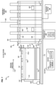
- FIG. 1 is a block diagram of a line assembly system 100 that includes an autoclave 180 for hardening preforms (i.e., curing thermoset preforms, re-heating and consolidating thermoplastic preforms) into composite parts in an illustrative embodiment.
- Line assembly system 100 comprises any system, device, or component operable to iteratively pulse a preform 170 for a half barrel section of fuselage (or other arcuate section of fuselage comprising skin and stringers) in a process direction 179.
- line assembly system 100 includes an autoclave 180 which hardens the preform 170 via the application of heat and pressure.
- the preform 170 is laid-up onto a layup mandrel 120 that proceeds in a process direction 179 along a factory floor 110, and is driven by an Autonomous Guided Vehicle (AGV) 130 or along a track 132 that leads to the autoclave 180.
- the layup mandrel 120 includes a perimeter 121.
- a caul plate 160 (or a vacuum bag) is placed over the preform 170, and follows a contour 162 of the preform 170.
- a layup surface 123 (see FIG. 5A ) of the layup mandrel 120 defines the contour 162 of the preform 170.
- the caul plate 160 seals the preform 170 to the layup mandrel 120 prior to sealing the layup mandrel 120 to an inner surface 186 of the autoclave 180.
- the caul plate 160 is sealed via vacuum to the layup mandrel 120 (e.g., via a vacuum system internal to the layup mandrel 120), which results in application of consolidation force to the preform 170.
- a vacuum bag e.g., vacuum bag 714 is utilized to perform this task.
- the layup mandrel 120 is driven into a hollow portion (e.g., passageway 189) of the autoclave 180 via entrance 722.
- a pressure chamber 187 (referred to herein as a vacuum, pressure, pressurized, or sealed chamber) for the preform 170.
- Perimeter seals 150 at the layup mandrel 120 seal against an inner surface 186 of the autoclave 180, which causes the autoclave 180 and the layup mandrel 120 together to form pressure chamber 187 in which the preform 170 is heated. That is, the perimeter seals 150 seal a perimeter 121 of the layup mandrel 120 to the inner surface 186 of the autoclave 180.
- the layup mandrel 120 also includes gap seals 124, which may comprise rigid or other thermal barriers for sealing gap 310 (e.g., an arcuate gap) by clamping to the autoclave 180 to form a pressure chamber 187 (i.e., any sealed/sealable chamber capable of supporting a different-than-atmospheric amount of pressure).
- the gap seals 124 are mounted via hinges 125 to the layup mandrel 120.
- the gap seals 124 may form an arcuate shape and may comprise rigid segments of material.
- hinge-mounted gap seals 124 are discussed, they are but one embodiment of sealing in an autoclave 180, and other types of seals may be utilized to engage layup mandrel 120, caul plate 160, and autoclave 180 in order to form the pressure chamber 187.
- the inner surface 186 of the autoclave 180 follows the contour 162 of the preform 170, it is complementary to the contour 162 and is separated by only a small distance (e.g. gap 310) from the contour 162 (e.g., less than 25.4 cm (ten inches), such as less than 5.08 cm (two inches)).
- a small distance e.g. gap 310
- heat and pressure applied to the pressure chamber 187 is applied to a smaller volume than in traditional autoclaves, which increases heating efficiency and hardening speed.
- the autoclave 180 has less thermal mass, and that smaller pieces of equipment may be used to pressurize the autoclave 180 (e.g., with nitrogen gas or other inert fluids).
- Heaters 182 are disposed within the autoclave 180 under an insulated shroud 188.
- the insulated shroud 188 includes vanes 184 which provide structural reinforcement to the autoclave 180 and facilitate the dissipation of heat after the autoclave 180 has completed a heating cycle.
- Heaters 182 at the autoclave 180 and heaters 122 at the layup mandrel 120 may comprise radiant heaters that increase a temperature of the chamber.
- heaters 122/182 are zonally controlled to ensure that temperature remains within an expected range uniformly across the entire surface of the preform 170. By continually monitoring and adjusting the amount of heat applied by the heaters 122/182 on a zone-by-zone basis, a temperature of the preform 170 is precisely controlled across the entirety of the preform 170.
- the heaters 122/182 are insulated from the exterior of the autoclave 180 and from the interior of the layup mandrel 120 by insulated shroud 188 and insulated shroud 128, respectively.
- the insulated shrouds 128/188 may comprise vacuum sealed or other thermally insulated regions.
- a pressure system 190 controls a pressure at the pressure chamber 187 during hardening/processing, for example, by drawing a vacuum within the pressure chamber 187 or increasing a pressure of the pressure chamber 187.
- vents 183 for driving heated gas into a vacuum chamber 187 formed between the layup mandrel 120, the autoclave 180, the perimeter seals 150, and the caul plate 160 are also provided.
- Including heaters 122/182 at the layup mandrel 120 and the autoclave 180 reduces the distance between the heaters 122/182 and the preform 170, which increases heat transfer efficiency.
- Using a "right sized" pressure chamber 187 that has little excess volume ensures that less gas (e.g., nitrogen gas or other inert fluid) is used by the line assembly system 100, which reduces material costs and also heat cycling time.
- the pressure chambers 187 discussed herein thereby reduce thermal mass and complexity of the autoclave structure, which reduces the amount of pressurized gas that needs to be stored.
- bladder 199 is disposed at the preform 170, and structurally supports any suitable hollow interior 170-1 of the preform 170 (e.g., a hollow interior 170-1 of a hat stringer disposed at the preform 170), thereby preventing the hollow interior 170-1 from collapsing during processing.
- the bladder 199 is therefore disposed underneath a caul plate 160 or vacuum bag that is used to consolidate the preform 170. In this manner, the bladder 199 supports a hollow interior 170-1 of the preform 170 against compaction caused by pressure applied by the autoclave 180.
- the bladder 199 communicates with a pressure chamber 187 formed by the autoclave 180, which means that when the pressure chamber 187 is pressurized, the bladder 199 is also pressurized and therefore inflates. In this manner, the bladder 199 is inflated via pressure from the pressure chamber 187.
- the vanes 184 at the autoclave 180 facilitate cooling of the autoclave 180 to a handling temperature at which the layup mandrel 120 and composite part 714 are removed in the process direction 179, and a next layup mandrel 120 can be inserted from upstream.
- two layup mandrels 120 are arranged in series or tandem, and placed into the autoclave 180 at the same time.
- each layup mandrel 120 may be sealed to the autoclave 180 to close a different door/entrance (e.g., entrance 722 or exit 724) of the autoclave 180.
- the next layup mandrel 120 is then inserted into the autoclave 180 and the process is repeated.
- This unique technical arrangement which enables a layup mandrel 120 to define part of the boundary of a chamber 187 of the autoclave 180, saves both energy and time. Furthermore, because the autoclave 180 has less thermal mass than traditional autoclaves, it may be rapidly heated and cooled, which reduces cycle time and increases throughput.
- the autoclave 180 itself forms part of a boundary or gated passageway 189 between a clean room environment 177 and an assembly region/environment 178 (which does not operate as a clean room environment).
- the autoclave 180 may be placed through a boundary 192, such as a shroud or wall that prevents dust from entering the clean room environment 177, with entrance 722 in the clean room environment 177.
- the autoclave 180 forms a portion of a boundary of a clean room environment 177.
- the composite part leaves the autoclave 180 via exit 724 and enters the assembly region 178.
- the autoclave 180 includes an inner surface 186 configured to slidably receive a layup mandrel 120, and to form a pressure chamber 187 in combination with the layup mandrel 120 after the layup mandrel 120 has been slidably received, and further defines an arcuate or contoured gap 310 defined by the inner surface 186 that is configured to receive a seal 124 that seals the layup mandrel 120 to the inner surface 186.
- the layup mandrel 120 defines a contour for a preform 170, and includes the perimeter seals 150 that seal the layup mandrel 120 to the autoclave 180 when the layup mandrel 120 is slid into the autoclave 180, and gap seals 124 that seal gap 310 (e.g., an arcuate gap) between the layup mandrel 120 and the autoclave 180 after the layup mandrel 120 is slid into the autoclave 180.
- the arcuate layup mandrel 120 and the arcuate autoclave 180 form complementary arcs.
- preforms 170 are heated in an autoclave 180, which is operated as a dedicated station with a full-length pulse corresponding with the length of a half barrel section of fuselage. Therefore, there may be an assembly line for layup prior to the autoclave 180 and an assembly line after the autoclave 180 with upper and lower half barrel sections on the line in series.
- the lower half barrel sections receive each type of work prior to the corresponding upper half barrel sections.
- the lower half barrel section may be hardened before the upper half barrel section, receive frames before the upper half barrel section, etc.
- the upper half barrel section and lower half barrel section are co-cured in a tandem autoclave, but the lower half barrel section exits the autoclave and enters an assembly line first.
- two half barrel sections are processed at the same time by the same autoclave 180.
- Layup mandrels 120 for the half barrel sections are arranged in tandem and sealed together or independently to the autoclave 180 and processed at the same time.
- a controller 197 comprising a processor 197-1 and a memory 197-2, manages the operations of the various components described herein, including for example, heaters 122/182, pressure system 190, autoclave 180, etc., to perform the methods described herein.
- controller 197 is implemented as custom circuitry, as a hardware processor executing programmed instructions stored in memory, or some combination thereof.
- line assembly system 100 Further details of the operation of line assembly system 100 will be discussed with regard to FIG. 2 . Assume, for this embodiment, that the layup mandrel 120 has received a preform 170, and that the preform 170 has been sealed onto the layup mandrel 120 via the application of caul plate 160. Hence, the preform 170 is ready to be hardened into a composite part 714.
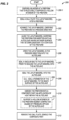
- FIG. 2 is a flowchart illustrating a method for operating a line assembly system to harden a preform in an autoclave an illustrative embodiment.
- the steps of method 200 are described with reference to line assembly system 100 of FIG. 1 , but those skilled in the art will appreciate that method 200 may be performed in other systems.
- the steps of the flowcharts described herein are not all inclusive and may include other steps not shown.
- the steps described herein may also be performed in an alternative order.
- the steps herein are described for half barrel sections, they may be applied to any suitable arcuate sections of fuselage, such as full barrel sections, one-quarter barrel sections, or other segment sizes.
- the autoclaves are dimensioned to harden any suitable structures, such as wing panels, spars, frames, floor beams, stabilizers, doors, etc.
- the insulated shroud 188 of the autoclave is sized and shaped to be complementary to a contour of a layup mandrel 120 for such components, and perimeter sealing 150 is used to seal the layup mandrel 120 to the autoclave 180.
- one or more bladders 199 are disposed at a preform 170 (optional step 200-1). These bladders 199 structurally support one or more hollow interiors 170-1 of the preform 170.
- Step 201 includes sealing a caul plate 160 to a layup mandrel 120 atop a preform 170. This comprises taping, suction-adhering, vacuum sealing, or otherwise securing the caul plate 160 against the preform 170 while preventing airflow from crossing the caul plate 160 to reach the preform 170.
- Step 202 includes advancing the layup mandrel 120 carrying the preform 170 in a process direction 179. This may comprise driving the layup mandrel 120 via the AGV 130, or advancing the layup mandrel 120 via tracks 132 that couple with the autoclave 180.
- the layup mandrel 120 has already advanced in the process direction 179 through multiple layup stations, as well as a preparation station at which the preform 170 is sealed to the layup mandrel 120. This may include sealing a caul plate 160 to the layup mandrel 120 prior to driving the layup mandrel 120 into the autoclave 180. In such embodiments, the caul plate 160 itself operates as a vacuum bag for the preform 170.
- Step 204 includes aligning the layup mandrel 120 for insertion into the autoclave 180, which has an inner surface 186 that follows/is complementary to a contour 162 of the preform 170. This may comprise placing the layup mandrel 120 into position such that driving the layup mandrel 120 in the process direction 179 results in insertion of the layup mandrel 120 into the autoclave 180 via entrance 722.
- an autoclave 180 of method 200 forms a pressure chamber 187 together with the layup mandrel 120 and any perimeter seals 150, gap seals 124, and/or shrouds 128.
- the seals and/or shrouds engage the autoclave shroud 188, which can be longitudinally open at the factory floor.
- the AGV 130 (or a tug, or manual cart) drives the layup mandrel 120 in the process direction 179 into the autoclave 180 via entrance 722, thereby nesting the preform 170 to the inner surface 186 of the autoclave 180.
- This may comprise aligning perimeter seals 150 with a complementary feature 185 (e.g., a groove or projection) at the inner surface 186, and mating the perimeter seals 150 with the complementary feature 185 at the inner surface 186 to form an airtight boundary.
- a complementary feature 185 e.g., a groove or projection
- an airtight seal is formed without the need for the complementary feature 185, by carefully dimensioning the perimeter seals 150.
- the airtight seal may be achieved via compression of a flexible coating or liner at the perimeter seals 150, which occurs when the perimeter seals 150 are driven into the complementary feature 185 of the autoclave 180.
- pairs of layup mandrels 120 in series are placed into the autoclave 180.
- pairs of layup mandrels 120 carrying separate half barrel sections may both be placed into the autoclave 180 in series, such that one layup mandrel 120 is downstream of the other layup mandrel 120 within the autoclave 180.
- Sealing a vacuum bag 717 to the layup mandrel 120 may be performed prior to sealing the layup mandrel 120 into the autoclave 180 (optional step 207).
- the layup mandrel 120 is sealed into the autoclave 180.
- This may comprise sealing gap 310 between the layup mandrel 120 and the autoclave 180 at either or both ends (e.g. entrance 722 and exit 724) of the autoclave 180 along the process direction 179.
- Sealing may comprise taping the gap closed, or closing the gap with a solid clamped plate (not shown) that acts an intermediary between the inner surface 186 and the layup mandrel 120.
- sealing may comprise sealing gap seals 124 that seal the gap 310 between the layup mandrel 120 and the autoclave 180 after the layup mandrel 120 is slid into the autoclave 180.
- a perimeter 121 of the layup mandrel 120 is sealed to the inner surface 186 of the autoclave 180 (optional step 209).
- each layup mandrel 120 may seal a separate entrance (e.g. entrance 722 or exit 722) (or portion thereof) of the autoclave 180.
- each may be sealed separately, or the layup mandrels 120 may utilize tandem sealing/joining techniques (e.g., where one layup mandrel 120 forms an upstream seal with the autoclave 180, and another layup mandrel 120 forms a downstream seal with the autoclave 180).
- the layup mandrel 120 defines a lower boundary of the autoclave 180 (i.e., a lower boundary of a pressure chamber 187 at the autoclave 180).
- sealing the layup mandrel 120 into the autoclave 180 comprises sealing an arcuate gap 310 between the preform 170 and the inner surface 186 of the autoclave 180.
- Step 210 includes hardening the preform 170 into a composite part 714 via application of heat and pressure within the autoclave 180.
- this comprises heating the preform 170 to a curing temperature and applying pressure to consolidate that preform 170 into a desired shape.
- this may comprise increasing a temperature of the preform 170 to a melting temperature of thermoplastic within the preform 170, consolidating the preform 170 under pressure, and cooling the preform 170 until it hardens/consolidates into a composite part 714.
- Hardening the preform 170 may comprise activating the heaters 122 in the layup mandrel 120 that are disposed under the preform 170 (e.g., beneath the layup surface 123), and/or activating the heaters 182 in the autoclave 180 that are disposed outside of the inner surface 186.
- the heaters 182 and/or 122 may comprise resistive heaters 126, susceptors 127 that respond to electromagnetic fields, etc.
- one or more bladders 199 may support one or more hollow interiors 170-1 of the preform 170 against compaction caused by pressure applied by the autoclave 180 (optional step 211).
- Step 212 includes removing the caul plate 160, performing any desired post-hardening trimming or machining, and demolding the composite part 714.
- the composite part 714 then receives additional work (e.g., installation of frames at the composite part, installation of windows at the composite part) and the layup mandrel 120 is cleaned.
- FIG. 3 is a perspective view of a preform 170 being inserted into an autoclave 180 (e.g., under an insulated shroud 188 of the autoclave 180) in an illustrative embodiment.
- FIG. 3 illustrates how the layup mandrel 120 forms a boundary of the autoclave 180 in the process direction 179, and further illustrates perimeter seals 150 interlocking with the autoclave 180.
- Gap seals 124 lock with a shroud 188 of the autoclave 180 to seal ends of the layup mandrel 120 into place. That is, gap seals 124 close the pressure chamber 187 by bridging gaps between the layup mandrel 120 and the autoclave 180 (e.g. at entrance 722 and exit 724, not show in FIG. 3 ).
- FIG. 3 illustrates that the arcuate gap 310 between the layup mandrel 120 and the inner surface 186 of autoclave 180 remains narrow (i.e., less than 25.4 cm (ten inches)) along the entirety of the contour 162 of the preform 170. That is, a volume between the layup mandrel 120 and the autoclave 180 is designed to be kept to a minimum to eliminate the amount of dead air space that must be heated and/or pressurized during operation. This reduction in stored energy dramatically reduces safety management approaches and system complexity when compared a traditional autoclave. This reduced volume provides an opportunity for zonal or local control of heating and pressurization if desired.
- FIG. 4 is a perspective view of an autoclave 180 into which a layup mandrel 120 has been inserted in an illustrative embodiment.
- a single layup mandrel 120 has been placed into the autoclave 180.
- multiple ones of the layup mandrels 120 may be placed into the autoclave 180 for curing at once.
- FIG. 5A which corresponds with view arrows 5A of FIG. 4 , shows a layup mandrel 120 prior to layup while awaiting entry into an autoclave 180.
- the layup surface 123 of the layup mandrel 120 defines a contour 162, and layup mandrel 120 includes heaters 122 beneath layup surface 123.
- layup has completed, and the layup mandrel 120 is covered by a preform 170 and a caul plate 160.
- FIG. 5C is an end view of the autoclave 180 of FIG. 4 in an illustrative embodiment, and corresponds with view arrows 5C of FIG. 4 .
- FIG. 5C makes clear that gap 310 between heaters 122 and heaters 182 is sealed by a cover 500 disposed between the layup mandrel 120 and the autoclave 180.
- the cover 500 is annular in shape, and may comprise a rigid tool or a flexible component that thermally insulates the autoclave 180 and is sealed to the autoclave 180.
- the autoclave 180 forms an upper boundary 512 of a pressure chamber 510, while the layup mandrel 120 (or a caul or preform molded thereto) forms a lower boundary 514 of the pressure chamber 510.
- FIG. 5D is a view of a further layup mandrel 560 and autoclave 550 for a wing panel in an illustrative embodiment.
- the layup mandrel 560 is inserted into an autoclave 550 that includes supports 552, lower wall 554, and upper wall 556.
- a preform 580 is laid-up onto a contour 562 of the layup mandrel 560, and a caul plate 570 covers the preform 580.
- the upper wall 556, supports 552, and the caul plate 570 form a pressure chamber 590 for hardening the preform 580.
- Perimeter seals 592 form boundaries of the pressure chamber 590 into and out of the page. For components of different dimensions, the perimeter seals 592 follow the different dimensions of layup mandrels for those components.
- FIG. 5E depicts a variety of sealing regimes for an autoclave 180 in an illustrative embodiment, and corresponds with region 5E of FIG. 5C .
- seals 500-40 directly contact an autoclave wall 500-30, and directly contact a caul plate 500-50 that contacts a layup mandrel surface 500-20.
- the seals 500-40 directly contact caul plate 500-50, which itself directly contacts the autoclave wall 500-30.
- the seals 500-40 also directly contact the layup mandrel surface 500-20.
- the seals 500-40 independently bridge the autoclave wall 500-30 and the layup mandrel surface 500-20, and the caul plate 500-50 terminates prior to reaching the seals 500-40.
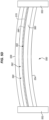
- FIG. 6 is side view of a layup mandrel 610 that includes extended regions for sealing to an autoclave in an illustrative embodiment.
- Layup mandrel 610 may be utilized to facilitate fabrication of a section of fuselage that has a smaller cross section or length than other sections of fuselage being fabricated via an autoclave.
- the layup mandrel 610 itself has a length L corresponding to a length of the autoclave, and includes extended regions 620 and 630 having heights H (and/or cross-sectional arcs) that correspond with entrances/exits of the autoclave.
- the extended regions 620 and 630 are capable of being sealed to the autoclave, because the layup mandrel 610 is dimensioned to match the autoclave, regardless of a size of the preform being hardened. Meanwhile, a layup region 640 is dimensioned to a contour for a preform that is smaller than other preforms used for the autoclave. Thus, the layup region 640 may exhibit a smaller diameter, height, or length than the autoclave, but this is compensated for by the dimensions of the layup mandrel 610.
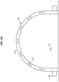
- FIG. 7 is a top view of an autoclave and preparation station in an illustrative embodiment.
- FIG. 7 illustrates layup mandrels 710 that receive preforms 170, and receive caul plates 716 and/or vacuum bags 717 at preparation station 718.
- the layup mandrels 710 are arranged in series for insertion into an autoclave 720 having entrance 722 at a first location and exit 724 at a second location separated by a distance in a process direction 779.
- the autoclave 720, entrance 722, and exit 724 are all arcuate. These processes may also be utilized, with modification to geometry as needed, to facilitate fabrication of wing panels, spars, ribs, or frames.
- the autoclave 720 forms a portion of an arcuate pressure chamber which is completed by inserting a layup mandrel 710 into the autoclave 720 and sealing the layup mandrel 710 into position.
- layup mandrels 710 After exiting the autoclave 720, layup mandrels 710 proceed to a debag station 730 that performs caul plate 716 removal and/or vacuum debagging, where a composite part 714 is demolded from the layup mandrels 710.
- the layup mandrels 710 and caul plates 716 are then cleaned and returned to a start of the fabrication line in order to receive a new preform 170 for a composite part 714.
- the composite part 714 continues in the process direction 779 for post cure processing into an aircraft (e.g., receiving fasteners, window installations, etc.). This process ensures that the layup mandrels 710 and caul plates 716 are capable of being rapidly and efficiently re-used, without the formation of waste products and without requiring an expansive amount of space at the factory floor.
- FIGS. 8-11 are flowcharts illustrating further techniques of operating layup mandrels and complementary autoclaves in illustrative embodiments. These methods will be described according to the autoclave 180 in FIG. 1 .
- FIG. 8 illustrates a method 800 of sealing an autoclave 180. The method includes driving or inserting a layup mandrel 120 in a process direction 179 into an autoclave 180 in step 802, and sealing an entrance 722 (and optionally an exit 724) of the autoclave 180 shut via seals 124 mounted at the layup mandrel 120 in step 804. Sealing the entrance 722 shut may comprise clamping the seals 124 to the autoclave 180 (optional step 806).
- a layup mandrel 120 is brought to within a desired distance (e.g. gap 310) of an autoclave 180 (e.g., a shroud 188 of the autoclave 180), bladders 199 at the layup mandrel 120 are enabled to receive pressure from the autoclave 180, and the perimeter 121 of the layup mandrel 120 is sealed to the autoclave 180 to form a pressure chamber 187, which is then pressurized.
- a desired distance e.g. gap 310
- an autoclave 180 e.g., a shroud 188 of the autoclave 180
- bladders 199 at the layup mandrel 120 are enabled to receive pressure from the autoclave 180, and the perimeter 121 of the layup mandrel 120 is sealed to the autoclave 180 to form a pressure chamber 187, which is then pressurized.
- the method further includes heating a preform 170 at the layup mandrel 120 via heaters 182 at the autoclave 180 and/or heating a preform 170 at the layup mandrel 120 via heaters 122 at the layup mandrel 120.
- the method further includes securing a preform 170 to the layup mandrel 120 by sealing edges of a caul plate 160 to the layup mandrel 120.
- driving the layup mandrel 120 into the autoclave 180 forms a pressure chamber 187 between the layup mandrel 120 and the autoclave 180.
- the method also includes driving the layup mandrel 120 in the process direction 179 out of the autoclave 180 via exit 724.
- sealing the entrance 722 comprises sealing an arcuate gap 310 between the layup mandrel 120 and the autoclave 180, thereby forming a thermally insulating barrier (optional step 808).
- the concepts discussed herein may be utilized for any suitable composite parts, such as wing panels, ribs, spars, and/or frames for an airframe of an aircraft.
- the shroud 188 of the autoclave 180 is dimensioned (i.e., sized and shaped) to be complementary to the contour (e.g., contour 562 of FIG. 5D ) of the layup mandrel 120 upon which a preform 170 has been placed.
- This complementary aspect enables the layup mandrel 120 itself to form a border of the autoclave 180, and enables a perimeter seal 150 to be used to seal the autoclave 180 and the layup mandrel 120 together.
- FIG. 9 depicts a method 900 of forming a pressure chamber 187 at an autoclave 180.
- the method includes driving a layup mandrel 120 in a process direction 179 into an autoclave 180 in step 902, forming a pressure chamber 187 having boundaries defined by the layup mandrel 120 and the autoclave 180 in step 904, and inflating one or more bladders 199 at a preform 170, which has been laid-up onto the layup mandrel 120, via pressure from the pressure chamber 187 in step 905.
- the bladders 199 support a hollow interior 170-1 of the preform 170 against compaction.
- Method 900 further includes hardening the preform 170 at the layup mandrel 120 into a composite part 714 in step 906.
- Hardening the preform 170 may comprise heating the preform 170 with heaters 122 at the layup mandrel 120 and/or heaters 182 at the autoclave 180 (optional step 912). In a further embodiment, hardening the preform 170 may comprise using heated gas from a pressure system 190 at the autoclave 180 to pressurize the pressure chamber 187 (optional step 914). Method 900 further includes removing the layup mandrel 120 in step 908.
- driving the layup mandrel 120 is performed via an Autonomous Guided Vehicle (AGV) 130, via a cart, via wheels, etc.
- AGV Autonomous Guided Vehicle
- the method 900 also includes demolding the composite part 714 from the layup mandrel 120 (optional step 910).
- the autoclave 180 forms a first boundary of the pressure chamber 187
- the layup mandrel 120 forms a second boundary of the pressure chamber 187
- the perimeter seals 150 form a third boundary.
- the pressure chamber 187 is arcuate, and forming a pressure chamber 187 comprises sealing an arcuate gap 310 (as well as longitudinal edges) between the layup mandrel 120 and the autoclave 180 (see step 804 of FIG. 8 ).
- sealing the arcuate gap 310 comprises forming a thermally insulating (and pressure retaining) barrier (see step 808 of FIG. 8 ).
- FIG. 10 illustrates a method 1000 of sealing an autoclave 180.
- the method includes driving (e.g., via an AGV, on rails, manually, etc.) a layup mandrel 120 in a process direction 179 into an autoclave 180 in step 1002, and heating a preform 170 at the layup mandrel 120 via heaters 122 disposed in the layup mandrel 120 and via heaters 182 disposed in the autoclave 180 in step 1004.
- Heating the preform 170 may comprise driving current through resistive heaters 126 at the layup mandrel 120 and the autoclave 180 (optional step 1006), or applying an electromagnetic field to susceptors 127 at the layup mandrel 120 and the autoclave 180 (optional step 1008).
- the preform 170 is heated via pressurized and heated gas pumped into the pressure chamber 187 of the autoclave 180.
- heating the preform 170 comprises increasing a temperature of the preform 170 to a curing temperature of a thermoset resin within the preform 170 (optional step 1010), or heating the preform 170 comprises increasing a temperature of the preform 170 to a melting temperature of a thermoplastic resin within the preform 170 (optional step 1012), after which the preform 170 is cooled below the melting temperature.
- the method 1000 further comprises securing a preform 170 to the layup mandrel 120 by sealing edges of a caul plate 160 to the layup mandrel 120.
- the method 1000 may further comprise driving the layup mandrel 120 in the process direction 179 out of the autoclave 180.
- the method 1000 may comprise sealing a gap 310 between the layup mandrel 120 and the autoclave 180 with a thermally insulating barrier (e.g., a seal).
- the layup mandrel 120 is dimensioned for extraction from the autoclave 180 via travel in the same process direction 179 that the layup mandrel 120 was inserted into the autoclave 180.
- the layup mandrel 120 forms a lower boundary of a chamber 187 of the autoclave 180 while inserted into the autoclave 180.
- FIG. 11 depicts a method 1100 of sealing an autoclave 180 in an illustrative embodiment.
- the method 1100 includes driving (e.g., via AGV 130, via rails, via manual carts, etc.) a layup mandrel 120 in a process direction 179 into an autoclave 180 in step 1102, and sealing the layup mandrel 120 to the autoclave 180 via seals 124/150, thereby forming a pressure chamber 187 bounded by the layup mandrel 120 and the autoclave 180 in step 1104.
- Method 1100 further includes hardening a preform 170 at the layup mandrel 120 into a composite part 714 in step 1106, and driving the layup mandrel 120 in the process direction 179 out of the autoclave 180 in step 1108.
- the autoclave 180 operates as a portal between a pre-cure/clean room environment 177 and a post hardening environment (e.g., assembly region 178).
- driving the layup mandrel 120 is performed via an Autonomous Guided Vehicle (AGV) 130.
- Method 1100 may further include demolding the composite part 714 from the layup mandrel 120 (optional step 1110).
- hardening the preform 170 comprises heating the preform 170 with heaters 122 at the layup mandrel 120 and/or heaters 182 at the autoclave 180 (see step 912 of FIG. 9 ).
- driving the layup mandrel 120 into the autoclave 180 forms the pressure chamber 187 between the layup mandrel 120 and the autoclave 180 (i.e., after perimeter seals 150 and/or other seals are in place).
- driving the layup mandrel 120 in the process direction 179 out of the autoclave 180 transitions the layup mandrel 120 out of a clean room environment 177. That is, the layup mandrel 120 is kept in a clean room environment 177 during layup and preparation, and then is moved into an autoclave 180 which forms a boundary between a clean room environment 177 and a non-clean room environment (e.g., assembly region 178). After hardening is completed, the layup mandrel 120 advances out of the autoclave 180 into the non-clean room environment, where demolding and trimming occurs. The layup mandrel 120 is then cleaned and returned to the clean room environment 177 to receive a preform 170 for another composite part 714.
- a non-clean room environment e.g., assembly region 178
- sealing the layup mandrel 120 to the autoclave 180 comprises sealing an arcuate gap 310 between the layup mandrel 120 and the autoclave 180 (see step 804 of FIG. 8 ). Sealing the arcuate gap 310 may comprise forming a thermally insulating barrier between the autoclave 180 and the layup mandrel 120 (see step 808 of FIG. 8 ).
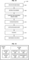
- FIG. 12 depicts a method 1200 of sealing an autoclave 180 in an illustrative embodiment.
- Method 1200 includes moving a preform 170 on a layup mandrel 120 from a clean room 177 into alignment with an autoclave 180 in step 1202.
- a caul plate 160 is placed over the preform 170, and conforms to the layup mandrel 120.
- Step 1204 includes sealing the layup mandrel 120 to the autoclave 180. In one embodiment, this results in a pressure chamber 187 between the caul plate 160 and the autoclave 180.
- the pressure chamber 187 is bounded by the autoclave 180 on one side and the caul plate 160 on another side.
- Step 1204 further includes hardening the preform 170 into a composite part 714 within the autoclave 180 in step 1206, and exiting the layup mandrel 120 from the autoclave 180 in step 1208. As the layup mandrel 120 exits from the autoclave 180, it has fully left the clean room environment 177 and enters an assembly environment 178 where demolding and trimming of the resulting composite part 714 is performed.
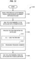
- FIG. 13 depicts a method 1300 of moving a preform 170 out of a clean room 177 in an illustrative embodiment.
- the method includes moving a preform 170 on a layup mandrel 120 from a clean room 177 into alignment with an autoclave 180 in step 1302, and sealing the layup mandrel 120 to the autoclave 180 with a perimeter seal 150 in step 1304. Sealing of the layup mandrel 120 to the autoclave 180 results in a pressure chamber 187 around the preform 170.
- Method 1300 further includes processing the preform 170 within the autoclave 180 in step 1306.
- Processing the preform 170 may include curing the preform 170 (optional step 1310), pressuring the pressure chamber 187 formed by the layup mandrel 120 and the autoclave 180 (optional step 1312), or other processing actions.
- Method 1300 further includes exiting the layup mandrel 120 from the autoclave 180 into a non-clean room (e.g., assembly region 178) in step 1308.
- method 1400 may include specification and design 1404 of the aircraft 1402 and material procurement 1406.
- component and subassembly manufacturing 1408 and system integration 1410 of the aircraft 1402 takes place.
- the aircraft 1402 may go through certification and delivery 1412 in order to be placed in service 1414.
- the aircraft 1402 is scheduled for routine work in maintenance and service 1416 (which may also include modification, reconfiguration, refurbishment, and so on).
- Apparatus and methods embodied herein may be employed during any one or more suitable stages of the production and service described in method 1400 (e.g., specification and design 1404, material procurement 1406, component and subassembly manufacturing 1408, system integration 1410, certification and delivery 1412, service 1414, maintenance and service 1416) and/or any suitable component of aircraft 1402 (e.g., airframe 1418, systems 1420, interior 1422, propulsion system 1424, electrical system 1426, hydraulic system 1428, environmental 1430).
- any suitable component of aircraft 1402 e.g., airframe 1418, systems 1420, interior 1422, propulsion system 1424, electrical system 1426, hydraulic system 1428, environmental 1430.
- a system integrator may include without limitation any number of aircraft manufacturers and major-system subcontractors; a third party may include without limitation any number of vendors, subcontractors, and suppliers; and an operator may be an airline, leasing company, military entity, service organization, and so on.
- the aircraft 1402 produced by method 1400 may include an airframe 1418 with a plurality of systems 1420 and an interior 1422.
- systems 1420 include one or more of a propulsion system 1424, an electrical system 1426, a hydraulic system 1428, and an environmental system 1430. Any number of other systems may be included.
- an aerospace example is shown, the principles of the present disclosure may be applied to other industries, such as the automotive industry.
- apparatus and methods embodied herein may be employed during any one or more of the stages of the production and service described in method 1400.
- components or subassemblies corresponding to component and subassembly manufacturing 1408 may be fabricated or manufactured in a manner similar to components or subassemblies produced while the aircraft 1402 is in service.
- one or more apparatus embodiments, method embodiments, or a combination thereof may be utilized during the subassembly manufacturing 1408 and system integration 1410, for example, by substantially expediting assembly of or reducing the cost of an aircraft 1402.
- one or more of apparatus embodiments, method embodiments, or a combination thereof may be utilized while the aircraft 1402 is in service, for example and without limitation during the maintenance and service 1416.
- the techniques and systems described herein may be used for material procurement 1406, component and subassembly manufacturing 1408, system integration 1410, service 1414, and/or maintenance and service 1416, and/or may be used for airframe 1418 and/or interior 1422.
- systems 1420 including, for example, propulsion system 1424, electrical system 1426, hydraulic 1428, and/or environmental system 1430.
- a part comprises a portion of airframe 1418, and is manufactured during component and subassembly manufacturing 1408.
- the part may then be assembled into an aircraft in system integration 1410, and then be utilized in service 1414 until wear renders the part unusable. Then, in maintenance and service 1416, the part may be discarded and replaced with a newly manufactured part.
- Inventive components and methods may be utilized throughout component and subassembly manufacturing 1408 in order to manufacture new parts.
- control elements e.g., electrical or electronic components
- a processor implementing software
- a processor implementing firmware or some combination of these.
- an element may be implemented as dedicated hardware.
- Dedicated hardware elements may be referred to as "processors", “controllers”, or some similar terminology.
- the functions may be provided by a single dedicated processor, by a single shared processor, or by a plurality of individual processors, some of which may be shared.
- processor or “controller” should not be construed to refer exclusively to hardware capable of executing software, and may implicitly include, without limitation, digital signal processor (DSP) hardware, a network processor, application specific integrated circuit (ASIC) or other circuitry, field programmable gate array (FPGA), read only memory (ROM) for storing software, random access memory (RAM), non-volatile storage, logic, or some other physical hardware component or module.
- DSP digital signal processor
- ASIC application specific integrated circuit
- FPGA field programmable gate array
- ROM read only memory
- RAM random access memory
- non-volatile storage logic, or some other physical hardware component or module.
- a control element may be implemented as instructions executable by a processor or a computer to perform the functions of the element.
- instructions are software, program code, and firmware.
- the instructions are operational when executed by the processor to direct the processor to perform the functions of the element.
- the instructions may be stored on storage devices that are readable by the processor. Some examples of the storage devices are digital or solid-state memories, magnetic storage media such as a magnetic disks and magnetic tapes, hard drives, or optically readable digital data storage media.
- a method (900) of forming a pressure chamber (187) at an autoclave comprising:
- driving (902) the layup mandrel (120) is performed via an Autonomous Guided Vehicle (AGV) (130).
- AGV Autonomous Guided Vehicle
- the method further comprises: demolding (910) a composite part (714) from the layup mandrel (120).
- hardening (906) the preform (170) comprises heating (912) the preform (170) with heaters (122) at the layup mandrel (120).
- hardening (906) the preform comprises heating (912) the preform with heaters (182) at the autoclave (180).
- hardening (906) the preform (170) comprises pressurizing (914) the pressure chamber (187) with a pressure system (190).
- the method further comprises: inflating (905) a bladder (199) at the preform (170) via pressure from the pressure chamber (187), wherein the bladder (199) supports a hollow interior (170-1) of the preform (170) against compaction.
- forming (904) the pressure chamber (187) comprises sealing (804) an arcuate gap (310) between the layup mandrel (120) and the autoclave (180).
- sealing (804) the arcuate gap (310) comprises forming (808) a thermally insulating barrier.
- a system (100) comprising:
- system further comprises: an Autonomous Guided Vehicle (AGV) (130) that drives the layup mandrel (120) into the hollow portion (189).
- AGV Autonomous Guided Vehicle
- layup mandrel (120) and the autoclave (180) both include heaters (122, 182) for hardening the preform (170) into the composite part (714).
- the system further comprises: a pressure system (190) that pressurizes the pressure chamber (187).
- the heaters (122, 182) comprise resistive heaters (126).
- the heaters (122, 182) comprise susceptors (127).
- the pressure chamber (187) is arcuate.
- the autoclave (180) forms a portion of a boundary (192) of a clean room environment (177).
- layup mandrel (120) is arcuate.
- the autoclave (180) further comprises vents (183) for driving heated air into the pressure chamber (187) formed between the layup mandrel (120) and the autoclave (180).
- a method (1300) of moving a preform (170) out of a clean room (177) comprising:
- processing (1306) the preform (170) comprises curing (1310) the preform (170).
- processing (1306) the preform (170) comprises pressurizing (1312) a pressure chamber (187) formed by the layup mandrel (120) and the autoclave (180).
Description
- The disclosure relates to the field of processing of airframe or other high-performance components, and in particular, to autoclave processing of such components.
- For fabrication of airframe or other high performance components made from composite materials, such as Carbon Fiber Reinforced Polymer (CFRP), autoclaves are utilized to harden uncured preforms into final part. Autoclaves are designed for processing composite components at elevated temperatures and or pressures and are heated by pumping heated gas into the autoclave at pressure. In a traditional factory environment, the autoclave itself may be designed to accommodate a wide range of component geometries or a plurality of components during the same processing cycle. This can result in large scale autoclaves which require a significant initial equipment investment, with substantial foundation, installation and auxiliary equipment costs.
- For large scale autoclaves, their large thermal mass and large volume for receiving a variety of component geometries require significant use of energy and gas, impacting utility costs for their operation. Significant time and energy are require to heat and pump the heated gas into the autoclave, and additional heated gas must be pumped in and maintained or replenished until the autoclave and its contents have reached a desired processing temperature and process time, further increasing operation costs.
- Large scale autoclaves may also hinder efficient assembly line flow within a factory environment, given their installation on a dedicated foundation and the use of gas storage tanks, such as for inert nitrogen, which need to position on an external wall. Further, the large scale, cost and operating costs of the autoclaves makes its use at the end of all pre-hardening fabrication processing in a centralized location, the norm. Transportation of components to and from the autoclave may not allow for optimized processing of components in a continuous or moving line manufacturing configuration. And the inherent time required for the heating, pressurizing, and cooling of such autoclaves further prohibits efficient processing time and factory operation.
- Therefore, it would be desirable to have a method and apparatus that take into account at least some of the issues discussed above, as well as other possible issues.
- The abstract of
US 4 997 511 A , states: "a method and apparatus for mass producing composite products comprising a novel autoclave having a cylindrical vacuum chamber; a cylindrical compression chamber surrounding the vacuum chamber; a reusable, flexible diaphragm defining the boundary between the chambers; and means for supplying heat and pressure between the diaphragm and the compression chamber. A core or mandrel is wrapped with a fiber-reinforced resin and is placed in the autoclave within the flexible diaphragm. Alternatively, a part layup can be sandwiched between an elastomeric caul and a hard tool by wrapping with expendable shrink tape to accommodate a variety of part shapes having constant or nearly constant cross sections throughout their length. The autoclave is then sealed and evacuated, causing the diaphragm to compress the resin layer against its core or mandrel due to atmospheric or higher pressure in the compression chamber. The autoclave is then heated to cure the resin. Subsequently, the autoclave is unsealed and the finished product is removed, with the autoclave immediately available for reuse." - The abstract of
WO 2021/032430 A1 , states: "the invention relates to a method and a device for producing a component from a fiber composite material (2), comprising the steps of: • introducing a plurality of layers (10, 11) of fibers impregnated with a matrix on an inner mould (3) within a mould space (9) formed between the inner mould (3) and an outer mold (4), • placing a membrane (6) sealed against the outer mould on the fibers impregnated with the matrix in such a way that a cavity (7) forms between the outer mould (4) and the membrane (6), which cavity extends along the lateral surface of the outer mould, and • subjecting the cavity (7) to a temperature-controllable pressure fluid at a temperature greater than the melting point of the matrix and at a pressure greater than the ambient pressure such that the temperature-controllable pressure fluid acts with the pressure onto the membrane. In order to produce a component having at least one reinforcing layer, which has a particularly smooth, stepless surface, it is proposed that at least one reinforcing layer (11), which has a smaller extension and fibers aligned predominantly in a parallel manner, is placed locally on a part of the side of a base layer (10) facing the outer mould (4). Subsequently, a membrane (6) having an average roughness depth of less than 1.0 µm, preferably less than 0.1 µm, exerts a set pressure on the component (2) in the cavity.". - Embodiments described herein provide autoclaves which receive preforms that have been laid-up in part of a continuous line fabrication process. The autoclaves are dimensioned to receive specific types of preforms, and include inner surfaces that correspond with contours defined by the preforms. One technical benefit is this reduces the amount of volume and mass that is heated within the autoclave, which reduces cycle time and increases efficiency. Furthermore, the autoclaves described herein may enable a hardened composite part to exit by continuing in the same direction that the autoclave was entered. This saves space on the factory floor, reducing expense.
- Other illustrative embodiments (e.g., methods and computer-readable media relating to the foregoing embodiments) may be described below. The features, functions, and advantages that have been discussed can be achieved independently in various embodiments or may be combined in yet other embodiments further details of which can be seen with reference to the following description and drawings.
- Some embodiments of the present disclosure are now described, by way of example only, and with reference to the accompanying drawings. The same reference number represents the same element or the same type of element on all drawings.
-
FIG. 1 is a block diagram of a line assembly system that includes an autoclave in an illustrative embodiment. -
FIG. 2 is a flowchart illustrating a method for operating a line assembly system to harden a preform in an autoclave an illustrative embodiment. -
FIG. 3 is a perspective view of a preform being inserted into an autoclave in an illustrative embodiment. -
FIG. 4 is a perspective view of an autoclave into which a layup mandrel has been inserted in an illustrative embodiment. -
FIGS. 5A-5C are views of the autoclave ofFIG. 4 in an illustrative embodiment. -
FIG. 5D is a view of a further layup mandrel and autoclave for a wing panel in an illustrative embodiment. -
FIG. 5E depicts a variety of sealing regimes for an autoclave in an illustrative embodiment. -
FIG. 6 is side view of a layup mandrel that includes extended regions for sealing to an autoclave in an illustrative embodiment. -
FIG. 7 is a top view of an autoclave and preparation station in an illustrative embodiment. -
FIGS. 8-12 are flowcharts illustrating further techniques of operating layup mandrels and complementary autoclaves in illustrative embodiments. -
FIG. 13 depicts amethod 1300 of moving a preform out of a clean room in an illustrative embodiment. -
FIG. 14 is a flow diagram of aircraft production and service methodology in an illustrative embodiment. -
FIG. 15 is a block diagram of an aircraft in an illustrative embodiment. - The figures and the following description provide specific illustrative embodiments of the disclosure. It will thus be appreciated that those skilled in the art will be able to devise various arrangements that, although not explicitly described or shown herein, embody the principles of the disclosure and are included within the scope of the disclosure. Furthermore, any examples described herein are intended to aid in understanding the principles of the disclosure, and are to be construed as being without limitation to such specifically recited examples and conditions. As a result, the disclosure is not limited to the specific embodiments or examples described below, but by the claims.
- Airframes may be implemented as composite parts. Composite parts, such as Carbon Fiber Reinforced Polymer (CFRP) parts, are initially laid-up in multiple layers that together are referred to as a preform. Individual fibers within each layer of the preform are aligned parallel with each other, but different layers may exhibit different fiber orientations in order to increase the strength of the resulting composite part along different dimensions. Alternatively, the preform may also include woven fiber fabric or materials with random or discontinuous fibers. The preform may include a viscous resin that solidifies in order to harden the preform into a composite part. Carbon fiber that has been impregnated with an uncured thermoset resin or a thermoplastic resin is referred to as "prepreg." Other types of carbon fiber include "dry fiber" which has not been impregnated with thermoset resin but may include a tackifier or binder. Dry fiber may be infused with resin prior to curing. For thermoset resins, the hardening is a one-way process referred to as curing, while for thermoplastic resins, the resin may reach a viscous form if it is re-heated.
-
FIG. 1 is a block diagram of aline assembly system 100 that includes anautoclave 180 for hardening preforms (i.e., curing thermoset preforms, re-heating and consolidating thermoplastic preforms) into composite parts in an illustrative embodiment.Line assembly system 100 comprises any system, device, or component operable to iteratively pulse apreform 170 for a half barrel section of fuselage (or other arcuate section of fuselage comprising skin and stringers) in aprocess direction 179. In this embodiment,line assembly system 100 includes anautoclave 180 which hardens thepreform 170 via the application of heat and pressure. - The
preform 170 is laid-up onto alayup mandrel 120 that proceeds in aprocess direction 179 along afactory floor 110, and is driven by an Autonomous Guided Vehicle (AGV) 130 or along atrack 132 that leads to theautoclave 180. Thelayup mandrel 120 includes aperimeter 121. A caul plate 160 (or a vacuum bag) is placed over thepreform 170, and follows acontour 162 of thepreform 170. A layup surface 123 (seeFIG. 5A ) of thelayup mandrel 120 defines thecontour 162 of thepreform 170. Thecaul plate 160 seals thepreform 170 to thelayup mandrel 120 prior to sealing thelayup mandrel 120 to aninner surface 186 of theautoclave 180. In this embodiment, thecaul plate 160 is sealed via vacuum to the layup mandrel 120 (e.g., via a vacuum system internal to the layup mandrel 120), which results in application of consolidation force to thepreform 170. In further embodiments, a vacuum bag (e.g., vacuum bag 714) is utilized to perform this task. During operation, thelayup mandrel 120 is driven into a hollow portion (e.g., passageway 189) of theautoclave 180 viaentrance 722. While thelayup mandrel 120 is inserted into theautoclave 180, thelayup mandrel 120 and theautoclave 180, along withperimeter seals 150 andcaul plate 160, define a pressure chamber 187 (referred to herein as a vacuum, pressure, pressurized, or sealed chamber) for thepreform 170. Perimeter seals 150 at thelayup mandrel 120 seal against aninner surface 186 of theautoclave 180, which causes theautoclave 180 and thelayup mandrel 120 together to formpressure chamber 187 in which thepreform 170 is heated. That is, the perimeter seals 150 seal aperimeter 121 of thelayup mandrel 120 to theinner surface 186 of theautoclave 180. In this embodiment, thelayup mandrel 120 also includes gap seals 124, which may comprise rigid or other thermal barriers for sealing gap 310 (e.g., an arcuate gap) by clamping to theautoclave 180 to form a pressure chamber 187 (i.e., any sealed/sealable chamber capable of supporting a different-than-atmospheric amount of pressure). The gap seals 124 are mounted viahinges 125 to thelayup mandrel 120. The gap seals 124 may form an arcuate shape and may comprise rigid segments of material. Although hinge-mounted gap seals 124 are discussed, they are but one embodiment of sealing in anautoclave 180, and other types of seals may be utilized to engagelayup mandrel 120,caul plate 160, andautoclave 180 in order to form thepressure chamber 187. - Because the
inner surface 186 of theautoclave 180 follows thecontour 162 of thepreform 170, it is complementary to thecontour 162 and is separated by only a small distance (e.g. gap 310) from the contour 162 (e.g., less than 25.4 cm (ten inches), such as less than 5.08 cm (two inches)). This means that heat and pressure applied to thepressure chamber 187 is applied to a smaller volume than in traditional autoclaves, which increases heating efficiency and hardening speed. This also means that theautoclave 180 has less thermal mass, and that smaller pieces of equipment may be used to pressurize the autoclave 180 (e.g., with nitrogen gas or other inert fluids). -
Heaters 182 are disposed within theautoclave 180 under aninsulated shroud 188. In this embodiment, theinsulated shroud 188 includesvanes 184 which provide structural reinforcement to theautoclave 180 and facilitate the dissipation of heat after theautoclave 180 has completed a heating cycle.Heaters 182 at theautoclave 180 andheaters 122 at thelayup mandrel 120 may comprise radiant heaters that increase a temperature of the chamber. In one embodiment,heaters 122/182 are zonally controlled to ensure that temperature remains within an expected range uniformly across the entire surface of thepreform 170. By continually monitoring and adjusting the amount of heat applied by theheaters 122/182 on a zone-by-zone basis, a temperature of thepreform 170 is precisely controlled across the entirety of thepreform 170. - The
heaters 122/182 are insulated from the exterior of theautoclave 180 and from the interior of thelayup mandrel 120 byinsulated shroud 188 andinsulated shroud 128, respectively. Theinsulated shrouds 128/188 may comprise vacuum sealed or other thermally insulated regions. Apressure system 190 controls a pressure at thepressure chamber 187 during hardening/processing, for example, by drawing a vacuum within thepressure chamber 187 or increasing a pressure of thepressure chamber 187. In this embodiment, vents 183 for driving heated gas into avacuum chamber 187 formed between thelayup mandrel 120, theautoclave 180, the perimeter seals 150, and thecaul plate 160 are also provided. Includingheaters 122/182 at thelayup mandrel 120 and theautoclave 180 reduces the distance between theheaters 122/182 and thepreform 170, which increases heat transfer efficiency. Using a "right sized"pressure chamber 187 that has little excess volume ensures that less gas (e.g., nitrogen gas or other inert fluid) is used by theline assembly system 100, which reduces material costs and also heat cycling time. Thepressure chambers 187 discussed herein thereby reduce thermal mass and complexity of the autoclave structure, which reduces the amount of pressurized gas that needs to be stored. - In some embodiments,
bladder 199 is disposed at thepreform 170, and structurally supports any suitable hollow interior 170-1 of the preform 170 (e.g., a hollow interior 170-1 of a hat stringer disposed at the preform 170), thereby preventing the hollow interior 170-1 from collapsing during processing. Thebladder 199 is therefore disposed underneath acaul plate 160 or vacuum bag that is used to consolidate thepreform 170. In this manner, thebladder 199 supports a hollow interior 170-1 of thepreform 170 against compaction caused by pressure applied by theautoclave 180. Thebladder 199 communicates with apressure chamber 187 formed by theautoclave 180, which means that when thepressure chamber 187 is pressurized, thebladder 199 is also pressurized and therefore inflates. In this manner, thebladder 199 is inflated via pressure from thepressure chamber 187. - After heating, the
vanes 184 at theautoclave 180 facilitate cooling of theautoclave 180 to a handling temperature at which thelayup mandrel 120 andcomposite part 714 are removed in theprocess direction 179, and anext layup mandrel 120 can be inserted from upstream. In a further embodiment, twolayup mandrels 120 are arranged in series or tandem, and placed into theautoclave 180 at the same time. In such embodiments, eachlayup mandrel 120 may be sealed to theautoclave 180 to close a different door/entrance (e.g.,entrance 722 or exit 724) of theautoclave 180. Thenext layup mandrel 120 is then inserted into theautoclave 180 and the process is repeated. This unique technical arrangement, which enables alayup mandrel 120 to define part of the boundary of achamber 187 of theautoclave 180, saves both energy and time. Furthermore, because theautoclave 180 has less thermal mass than traditional autoclaves, it may be rapidly heated and cooled, which reduces cycle time and increases throughput. - In this embodiment, the
autoclave 180 itself forms part of a boundary orgated passageway 189 between aclean room environment 177 and an assembly region/environment 178 (which does not operate as a clean room environment). For example, theautoclave 180 may be placed through aboundary 192, such as a shroud or wall that prevents dust from entering theclean room environment 177, withentrance 722 in theclean room environment 177. Thus, theautoclave 180 forms a portion of a boundary of aclean room environment 177. Upon completion of processing of thepreform 170 into acomposite part 714, the composite part leaves theautoclave 180 viaexit 724 and enters theassembly region 178. - To restate the above, the
autoclave 180 includes aninner surface 186 configured to slidably receive alayup mandrel 120, and to form apressure chamber 187 in combination with thelayup mandrel 120 after thelayup mandrel 120 has been slidably received, and further defines an arcuate or contouredgap 310 defined by theinner surface 186 that is configured to receive aseal 124 that seals thelayup mandrel 120 to theinner surface 186. Thelayup mandrel 120 defines a contour for apreform 170, and includes the perimeter seals 150 that seal thelayup mandrel 120 to theautoclave 180 when thelayup mandrel 120 is slid into theautoclave 180, and gap seals 124 that seal gap 310 (e.g., an arcuate gap) between thelayup mandrel 120 and theautoclave 180 after thelayup mandrel 120 is slid into theautoclave 180. In this manner, thearcuate layup mandrel 120 and thearcuate autoclave 180 form complementary arcs. - In one embodiment, preforms 170 are heated in an
autoclave 180, which is operated as a dedicated station with a full-length pulse corresponding with the length of a half barrel section of fuselage. Therefore, there may be an assembly line for layup prior to theautoclave 180 and an assembly line after theautoclave 180 with upper and lower half barrel sections on the line in series. When lower half barrel sections are downstream of upper half barrel sections, the lower half barrel sections receive each type of work prior to the corresponding upper half barrel sections. For example, the lower half barrel section may be hardened before the upper half barrel section, receive frames before the upper half barrel section, etc. In one embodiment, the upper half barrel section and lower half barrel section are co-cured in a tandem autoclave, but the lower half barrel section exits the autoclave and enters an assembly line first. In one embodiment, two half barrel sections are processed at the same time by thesame autoclave 180.Layup mandrels 120 for the half barrel sections are arranged in tandem and sealed together or independently to theautoclave 180 and processed at the same time. - A
controller 197, comprising a processor 197-1 and a memory 197-2, manages the operations of the various components described herein, including for example,heaters 122/182,pressure system 190,autoclave 180, etc., to perform the methods described herein. In one embodiment,controller 197 is implemented as custom circuitry, as a hardware processor executing programmed instructions stored in memory, or some combination thereof. - Further details of the operation of
line assembly system 100 will be discussed with regard toFIG. 2 . Assume, for this embodiment, that thelayup mandrel 120 has received apreform 170, and that thepreform 170 has been sealed onto thelayup mandrel 120 via the application ofcaul plate 160. Hence, thepreform 170 is ready to be hardened into acomposite part 714. -
FIG. 2 is a flowchart illustrating a method for operating a line assembly system to harden a preform in an autoclave an illustrative embodiment. The steps of method 200 are described with reference toline assembly system 100 ofFIG. 1 , but those skilled in the art will appreciate that method 200 may be performed in other systems. The steps of the flowcharts described herein are not all inclusive and may include other steps not shown. The steps described herein may also be performed in an alternative order. Furthermore, although the steps herein are described for half barrel sections, they may be applied to any suitable arcuate sections of fuselage, such as full barrel sections, one-quarter barrel sections, or other segment sizes. In further embodiments, the autoclaves are dimensioned to harden any suitable structures, such as wing panels, spars, frames, floor beams, stabilizers, doors, etc. In such cases, theinsulated shroud 188 of the autoclave is sized and shaped to be complementary to a contour of alayup mandrel 120 for such components, and perimeter sealing 150 is used to seal thelayup mandrel 120 to theautoclave 180. In one embodiment, prior to sealing, one ormore bladders 199 are disposed at a preform 170 (optional step 200-1). Thesebladders 199 structurally support one or more hollow interiors 170-1 of thepreform 170. - Step 201 includes sealing a
caul plate 160 to alayup mandrel 120 atop apreform 170. This comprises taping, suction-adhering, vacuum sealing, or otherwise securing thecaul plate 160 against thepreform 170 while preventing airflow from crossing thecaul plate 160 to reach thepreform 170. Step 202 includes advancing thelayup mandrel 120 carrying thepreform 170 in aprocess direction 179. This may comprise driving thelayup mandrel 120 via theAGV 130, or advancing thelayup mandrel 120 viatracks 132 that couple with theautoclave 180. In one embodiment, thelayup mandrel 120 has already advanced in theprocess direction 179 through multiple layup stations, as well as a preparation station at which thepreform 170 is sealed to thelayup mandrel 120. This may include sealing acaul plate 160 to thelayup mandrel 120 prior to driving thelayup mandrel 120 into theautoclave 180. In such embodiments, thecaul plate 160 itself operates as a vacuum bag for thepreform 170. - Step 204 includes aligning the
layup mandrel 120 for insertion into theautoclave 180, which has aninner surface 186 that follows/is complementary to acontour 162 of thepreform 170. This may comprise placing thelayup mandrel 120 into position such that driving thelayup mandrel 120 in theprocess direction 179 results in insertion of thelayup mandrel 120 into theautoclave 180 viaentrance 722. Thus, unlike autoclaves which themselves define all walls/boundaries of a pressure chamber, anautoclave 180 of method 200 forms apressure chamber 187 together with thelayup mandrel 120 and any perimeter seals 150, gap seals 124, and/or shrouds 128. The seals and/or shrouds engage theautoclave shroud 188, which can be longitudinally open at the factory floor. - In
step 206, the AGV 130 (or a tug, or manual cart) drives thelayup mandrel 120 in theprocess direction 179 into theautoclave 180 viaentrance 722, thereby nesting thepreform 170 to theinner surface 186 of theautoclave 180. This may comprise aligning perimeter seals 150 with a complementary feature 185 (e.g., a groove or projection) at theinner surface 186, and mating the perimeter seals 150 with thecomplementary feature 185 at theinner surface 186 to form an airtight boundary. In further embodiments, an airtight seal is formed without the need for thecomplementary feature 185, by carefully dimensioning the perimeter seals 150. Because theinner surface 186 follows thecontour 162, driving thelayup mandrel 120 into theautoclave 180 results in agap 310 between theinner surface 186 of theautoclave 180 and thecontour 162 of thepreform 170 of less than 25.4 cm (ten inches) (e.g., less than 5.08 cm (two inches)). The airtight seal may be achieved via compression of a flexible coating or liner at the perimeter seals 150, which occurs when the perimeter seals 150 are driven into thecomplementary feature 185 of theautoclave 180. In further embodiments, pairs oflayup mandrels 120 in series are placed into theautoclave 180. For example, pairs oflayup mandrels 120 carrying separate half barrel sections (that will later be joined into a full barrel section after the half barrel sections are hardened and demolded), may both be placed into theautoclave 180 in series, such that onelayup mandrel 120 is downstream of theother layup mandrel 120 within theautoclave 180. Sealing avacuum bag 717 to thelayup mandrel 120 may be performed prior to sealing thelayup mandrel 120 into the autoclave 180 (optional step 207). - In
step 208, thelayup mandrel 120 is sealed into theautoclave 180. This may comprise sealinggap 310 between thelayup mandrel 120 and theautoclave 180 at either or both ends (e.g. entrance 722 and exit 724) of theautoclave 180 along theprocess direction 179. Sealing may comprise taping the gap closed, or closing the gap with a solid clamped plate (not shown) that acts an intermediary between theinner surface 186 and thelayup mandrel 120. In some embodiments, sealing may comprise sealing gap seals 124 that seal thegap 310 between thelayup mandrel 120 and theautoclave 180 after thelayup mandrel 120 is slid into theautoclave 180. In one embodiment, aperimeter 121 of thelayup mandrel 120 is sealed to theinner surface 186 of the autoclave 180 (optional step 209). In embodiments withmultiple layup mandrels 120 placed into the autoclave (e.g., in series), eachlayup mandrel 120 may seal a separate entrance (e.g. entrance 722 or exit 722) (or portion thereof) of theautoclave 180. When thelayup mandrels 120 are arranged in series, each may be sealed separately, or thelayup mandrels 120 may utilize tandem sealing/joining techniques (e.g., where onelayup mandrel 120 forms an upstream seal with theautoclave 180, and anotherlayup mandrel 120 forms a downstream seal with the autoclave 180). After the sealing has been completed, thelayup mandrel 120 defines a lower boundary of the autoclave 180 (i.e., a lower boundary of apressure chamber 187 at the autoclave 180). In one embodiment, sealing thelayup mandrel 120 into theautoclave 180 comprises sealing anarcuate gap 310 between thepreform 170 and theinner surface 186 of theautoclave 180. - Step 210 includes hardening the
preform 170 into acomposite part 714 via application of heat and pressure within theautoclave 180. For thermoset preforms, this comprises heating thepreform 170 to a curing temperature and applying pressure to consolidate thatpreform 170 into a desired shape. For thermoplastic preforms, this may comprise increasing a temperature of thepreform 170 to a melting temperature of thermoplastic within thepreform 170, consolidating thepreform 170 under pressure, and cooling thepreform 170 until it hardens/consolidates into acomposite part 714. Hardening thepreform 170 may comprise activating theheaters 122 in thelayup mandrel 120 that are disposed under the preform 170 (e.g., beneath the layup surface 123), and/or activating theheaters 182 in theautoclave 180 that are disposed outside of theinner surface 186. Theheaters 182 and/or 122 may comprise resistive heaters 126,susceptors 127 that respond to electromagnetic fields, etc. During hardening, one ormore bladders 199 may support one or more hollow interiors 170-1 of thepreform 170 against compaction caused by pressure applied by the autoclave 180 (optional step 211). - After the
composite part 714 has been hardened, theautoclave 180 is unsealed, and thelayup mandrel 120 may proceed in theprocess direction 179 out of theautoclave 180 viaexit 724 in order to receive further work. Step 212 includes removing thecaul plate 160, performing any desired post-hardening trimming or machining, and demolding thecomposite part 714. Thecomposite part 714 then receives additional work (e.g., installation of frames at the composite part, installation of windows at the composite part) and thelayup mandrel 120 is cleaned. -
FIG. 3 is a perspective view of apreform 170 being inserted into an autoclave 180 (e.g., under aninsulated shroud 188 of the autoclave 180) in an illustrative embodiment.FIG. 3 illustrates how thelayup mandrel 120 forms a boundary of theautoclave 180 in theprocess direction 179, and further illustrates perimeter seals 150 interlocking with theautoclave 180. Gap seals 124 lock with ashroud 188 of theautoclave 180 to seal ends of thelayup mandrel 120 into place. That is, gap seals 124 close thepressure chamber 187 by bridging gaps between thelayup mandrel 120 and the autoclave 180 (e.g. atentrance 722 andexit 724, not show inFIG. 3 ). - Furthermore,
FIG. 3 illustrates that thearcuate gap 310 between thelayup mandrel 120 and theinner surface 186 ofautoclave 180 remains narrow (i.e., less than 25.4 cm (ten inches)) along the entirety of thecontour 162 of thepreform 170. That is, a volume between thelayup mandrel 120 and theautoclave 180 is designed to be kept to a minimum to eliminate the amount of dead air space that must be heated and/or pressurized during operation. This reduction in stored energy dramatically reduces safety management approaches and system complexity when compared a traditional autoclave. This reduced volume provides an opportunity for zonal or local control of heating and pressurization if desired. -
FIG. 4 is a perspective view of anautoclave 180 into which alayup mandrel 120 has been inserted in an illustrative embodiment. In this embodiment, asingle layup mandrel 120 has been placed into theautoclave 180. However, in further embodiments, multiple ones of thelayup mandrels 120 may be placed into theautoclave 180 for curing at once. -
FIG. 5A , which corresponds withview arrows 5A ofFIG. 4 , shows alayup mandrel 120 prior to layup while awaiting entry into anautoclave 180. Thelayup surface 123 of thelayup mandrel 120 defines acontour 162, andlayup mandrel 120 includesheaters 122 beneathlayup surface 123. InFIG. 5B , layup has completed, and thelayup mandrel 120 is covered by apreform 170 and acaul plate 160. -
FIG. 5C is an end view of theautoclave 180 ofFIG. 4 in an illustrative embodiment, and corresponds withview arrows 5C ofFIG. 4 .FIG. 5C makes clear thatgap 310 betweenheaters 122 andheaters 182 is sealed by acover 500 disposed between thelayup mandrel 120 and theautoclave 180. Thecover 500 is annular in shape, and may comprise a rigid tool or a flexible component that thermally insulates theautoclave 180 and is sealed to theautoclave 180. In this embodiment, theautoclave 180 forms anupper boundary 512 of apressure chamber 510, while the layup mandrel 120 (or a caul or preform molded thereto) forms alower boundary 514 of thepressure chamber 510. Seals may be applied inregion 5E in order to form apressure chamber 187.FIG. 5D is a view of afurther layup mandrel 560 andautoclave 550 for a wing panel in an illustrative embodiment. In this embodiment, thelayup mandrel 560 is inserted into anautoclave 550 that includessupports 552,lower wall 554, andupper wall 556. Apreform 580 is laid-up onto acontour 562 of thelayup mandrel 560, and acaul plate 570 covers thepreform 580. Together, theupper wall 556, supports 552, and thecaul plate 570 form apressure chamber 590 for hardening thepreform 580. Perimeter seals 592 form boundaries of thepressure chamber 590 into and out of the page. For components of different dimensions, the perimeter seals 592 follow the different dimensions of layup mandrels for those components. -
FIG. 5E depicts a variety of sealing regimes for anautoclave 180 in an illustrative embodiment, and corresponds withregion 5E ofFIG. 5C . In a first arrangement 500-10 depicted on the left, seals 500-40 directly contact an autoclave wall 500-30, and directly contact a caul plate 500-50 that contacts a layup mandrel surface 500-20. In a second arrangement 500-12, the seals 500-40 directly contact caul plate 500-50, which itself directly contacts the autoclave wall 500-30. The seals 500-40 also directly contact the layup mandrel surface 500-20. In a third arrangement 500-14, the seals 500-40 independently bridge the autoclave wall 500-30 and the layup mandrel surface 500-20, and the caul plate 500-50 terminates prior to reaching the seals 500-40. -
FIG. 6 is side view of a layup mandrel 610 that includes extended regions for sealing to an autoclave in an illustrative embodiment. Layup mandrel 610 may be utilized to facilitate fabrication of a section of fuselage that has a smaller cross section or length than other sections of fuselage being fabricated via an autoclave. The layup mandrel 610 itself has a length L corresponding to a length of the autoclave, and includesextended regions extended regions layup region 640 is dimensioned to a contour for a preform that is smaller than other preforms used for the autoclave. Thus, thelayup region 640 may exhibit a smaller diameter, height, or length than the autoclave, but this is compensated for by the dimensions of the layup mandrel 610. -
FIG. 7 is a top view of an autoclave and preparation station in an illustrative embodiment.FIG. 7 illustrateslayup mandrels 710 that receive preforms 170, and receivecaul plates 716 and/orvacuum bags 717 atpreparation station 718. The layup mandrels 710 are arranged in series for insertion into anautoclave 720 havingentrance 722 at a first location and exit 724 at a second location separated by a distance in aprocess direction 779. In one embodiment, theautoclave 720,entrance 722, andexit 724 are all arcuate. These processes may also be utilized, with modification to geometry as needed, to facilitate fabrication of wing panels, spars, ribs, or frames. Theautoclave 720 forms a portion of an arcuate pressure chamber which is completed by inserting alayup mandrel 710 into theautoclave 720 and sealing thelayup mandrel 710 into position. - After exiting the
autoclave 720,layup mandrels 710 proceed to adebag station 730 that performscaul plate 716 removal and/or vacuum debagging, where acomposite part 714 is demolded from the layup mandrels 710. The layup mandrels 710 andcaul plates 716 are then cleaned and returned to a start of the fabrication line in order to receive anew preform 170 for acomposite part 714. Thecomposite part 714 continues in theprocess direction 779 for post cure processing into an aircraft (e.g., receiving fasteners, window installations, etc.). This process ensures that thelayup mandrels 710 andcaul plates 716 are capable of being rapidly and efficiently re-used, without the formation of waste products and without requiring an expansive amount of space at the factory floor. -
FIGS. 8-11 are flowcharts illustrating further techniques of operating layup mandrels and complementary autoclaves in illustrative embodiments. These methods will be described according to theautoclave 180 inFIG. 1 .FIG. 8 illustrates amethod 800 of sealing anautoclave 180. The method includes driving or inserting alayup mandrel 120 in aprocess direction 179 into anautoclave 180 instep 802, and sealing an entrance 722 (and optionally an exit 724) of theautoclave 180 shut viaseals 124 mounted at thelayup mandrel 120 instep 804. Sealing theentrance 722 shut may comprise clamping theseals 124 to the autoclave 180 (optional step 806). Thus, according to the processes described above, alayup mandrel 120 is brought to within a desired distance (e.g. gap 310) of an autoclave 180 (e.g., ashroud 188 of the autoclave 180),bladders 199 at thelayup mandrel 120 are enabled to receive pressure from theautoclave 180, and theperimeter 121 of thelayup mandrel 120 is sealed to theautoclave 180 to form apressure chamber 187, which is then pressurized. - In another embodiment, the method further includes heating a
preform 170 at thelayup mandrel 120 viaheaters 182 at theautoclave 180 and/or heating apreform 170 at thelayup mandrel 120 viaheaters 122 at thelayup mandrel 120. In a further embodiment, the method further includes securing apreform 170 to thelayup mandrel 120 by sealing edges of acaul plate 160 to thelayup mandrel 120. In yet another embodiment, driving thelayup mandrel 120 into theautoclave 180 forms apressure chamber 187 between thelayup mandrel 120 and theautoclave 180. This involves bringing three separate elements (perimeter seals 150,caul plate 160, autoclave 180) together to form apressure chamber 187, and then removing several of the components when hardening is completed. In a still further embodiment, the method also includes driving thelayup mandrel 120 in theprocess direction 179 out of theautoclave 180 viaexit 724. In yet another embodiment, sealing theentrance 722 comprises sealing anarcuate gap 310 between thelayup mandrel 120 and theautoclave 180, thereby forming a thermally insulating barrier (optional step 808). The concepts discussed herein may be utilized for any suitable composite parts, such as wing panels, ribs, spars, and/or frames for an airframe of an aircraft. In such embodiments, theshroud 188 of theautoclave 180 is dimensioned (i.e., sized and shaped) to be complementary to the contour (e.g.,contour 562 ofFIG. 5D ) of thelayup mandrel 120 upon which apreform 170 has been placed. This complementary aspect enables thelayup mandrel 120 itself to form a border of theautoclave 180, and enables aperimeter seal 150 to be used to seal theautoclave 180 and thelayup mandrel 120 together. -
FIG. 9 depicts amethod 900 of forming apressure chamber 187 at anautoclave 180. The method includes driving alayup mandrel 120 in aprocess direction 179 into anautoclave 180 instep 902, forming apressure chamber 187 having boundaries defined by thelayup mandrel 120 and theautoclave 180 instep 904, and inflating one ormore bladders 199 at apreform 170, which has been laid-up onto thelayup mandrel 120, via pressure from thepressure chamber 187 in step 905. Thebladders 199 support a hollow interior 170-1 of thepreform 170 against compaction.Method 900 further includes hardening thepreform 170 at thelayup mandrel 120 into acomposite part 714 instep 906. Hardening thepreform 170 may comprise heating thepreform 170 withheaters 122 at thelayup mandrel 120 and/orheaters 182 at the autoclave 180 (optional step 912). In a further embodiment, hardening thepreform 170 may comprise using heated gas from apressure system 190 at theautoclave 180 to pressurize the pressure chamber 187 (optional step 914).Method 900 further includes removing thelayup mandrel 120 instep 908. - In a further embodiment, driving the
layup mandrel 120 is performed via an Autonomous Guided Vehicle (AGV) 130, via a cart, via wheels, etc. In a further embodiment, themethod 900 also includes demolding thecomposite part 714 from the layup mandrel 120 (optional step 910). In a further embodiment, theautoclave 180 forms a first boundary of thepressure chamber 187, thelayup mandrel 120 forms a second boundary of thepressure chamber 187, and the perimeter seals 150 form a third boundary. In a further embodiment, thepressure chamber 187 is arcuate, and forming apressure chamber 187 comprises sealing an arcuate gap 310 (as well as longitudinal edges) between thelayup mandrel 120 and the autoclave 180 (seestep 804 ofFIG. 8 ). In yet another embodiment, sealing thearcuate gap 310 comprises forming a thermally insulating (and pressure retaining) barrier (seestep 808 ofFIG. 8 ). -
FIG. 10 illustrates a method 1000 of sealing anautoclave 180. The method includes driving (e.g., via an AGV, on rails, manually, etc.) alayup mandrel 120 in aprocess direction 179 into anautoclave 180 instep 1002, and heating apreform 170 at thelayup mandrel 120 viaheaters 122 disposed in thelayup mandrel 120 and viaheaters 182 disposed in theautoclave 180 instep 1004. Heating thepreform 170 may comprise driving current through resistive heaters 126 at thelayup mandrel 120 and the autoclave 180 (optional step 1006), or applying an electromagnetic field tosusceptors 127 at thelayup mandrel 120 and the autoclave 180 (optional step 1008). In a still further embodiment, thepreform 170 is heated via pressurized and heated gas pumped into thepressure chamber 187 of theautoclave 180. In a still further embodiment, heating thepreform 170 comprises increasing a temperature of thepreform 170 to a curing temperature of a thermoset resin within the preform 170 (optional step 1010), or heating thepreform 170 comprises increasing a temperature of thepreform 170 to a melting temperature of a thermoplastic resin within the preform 170 (optional step 1012), after which thepreform 170 is cooled below the melting temperature. - In further embodiments, the method 1000 further comprises securing a
preform 170 to thelayup mandrel 120 by sealing edges of acaul plate 160 to thelayup mandrel 120. After thepreform 170 has been hardened, the method 1000 may further comprise driving thelayup mandrel 120 in theprocess direction 179 out of theautoclave 180. Furthermore, prior to heating, the method 1000 may comprise sealing agap 310 between thelayup mandrel 120 and theautoclave 180 with a thermally insulating barrier (e.g., a seal). Thelayup mandrel 120 is dimensioned for extraction from theautoclave 180 via travel in thesame process direction 179 that thelayup mandrel 120 was inserted into theautoclave 180. Furthermore, thelayup mandrel 120 forms a lower boundary of achamber 187 of theautoclave 180 while inserted into theautoclave 180. -
FIG. 11 depicts amethod 1100 of sealing anautoclave 180 in an illustrative embodiment. Themethod 1100 includes driving (e.g., viaAGV 130, via rails, via manual carts, etc.) alayup mandrel 120 in aprocess direction 179 into anautoclave 180 instep 1102, and sealing thelayup mandrel 120 to theautoclave 180 viaseals 124/150, thereby forming apressure chamber 187 bounded by thelayup mandrel 120 and theautoclave 180 instep 1104.Method 1100 further includes hardening apreform 170 at thelayup mandrel 120 into acomposite part 714 instep 1106, and driving thelayup mandrel 120 in theprocess direction 179 out of theautoclave 180 instep 1108. Theautoclave 180 operates as a portal between a pre-cure/clean room environment 177 and a post hardening environment (e.g., assembly region 178). - In a further embodiment, driving the
layup mandrel 120 is performed via an Autonomous Guided Vehicle (AGV) 130.Method 1100 may further include demolding thecomposite part 714 from the layup mandrel 120 (optional step 1110). In one embodiment, hardening thepreform 170 comprises heating thepreform 170 withheaters 122 at thelayup mandrel 120 and/orheaters 182 at the autoclave 180 (seestep 912 ofFIG. 9 ). In one embodiment, driving thelayup mandrel 120 into theautoclave 180 forms thepressure chamber 187 between thelayup mandrel 120 and the autoclave 180 (i.e., after perimeter seals 150 and/or other seals are in place). In a further embodiment, driving thelayup mandrel 120 in theprocess direction 179 out of theautoclave 180 transitions thelayup mandrel 120 out of aclean room environment 177. That is, thelayup mandrel 120 is kept in aclean room environment 177 during layup and preparation, and then is moved into anautoclave 180 which forms a boundary between aclean room environment 177 and a non-clean room environment (e.g., assembly region 178). After hardening is completed, thelayup mandrel 120 advances out of theautoclave 180 into the non-clean room environment, where demolding and trimming occurs. Thelayup mandrel 120 is then cleaned and returned to theclean room environment 177 to receive apreform 170 for anothercomposite part 714. - In one embodiment, sealing the
layup mandrel 120 to theautoclave 180 comprises sealing anarcuate gap 310 between thelayup mandrel 120 and the autoclave 180 (seestep 804 ofFIG. 8 ). Sealing thearcuate gap 310 may comprise forming a thermally insulating barrier between theautoclave 180 and the layup mandrel 120 (seestep 808 ofFIG. 8 ). -
FIG. 12 depicts amethod 1200 of sealing anautoclave 180 in an illustrative embodiment.Method 1200 includes moving apreform 170 on alayup mandrel 120 from aclean room 177 into alignment with anautoclave 180 instep 1202. In one embodiment, acaul plate 160 is placed over thepreform 170, and conforms to thelayup mandrel 120.Step 1204 includes sealing thelayup mandrel 120 to theautoclave 180. In one embodiment, this results in apressure chamber 187 between thecaul plate 160 and theautoclave 180. Thepressure chamber 187 is bounded by theautoclave 180 on one side and thecaul plate 160 on another side.Step 1204 further includes hardening thepreform 170 into acomposite part 714 within theautoclave 180 instep 1206, and exiting thelayup mandrel 120 from theautoclave 180 instep 1208. As thelayup mandrel 120 exits from theautoclave 180, it has fully left theclean room environment 177 and enters anassembly environment 178 where demolding and trimming of the resultingcomposite part 714 is performed. -
FIG. 13 depicts amethod 1300 of moving apreform 170 out of aclean room 177 in an illustrative embodiment. The method includes moving apreform 170 on alayup mandrel 120 from aclean room 177 into alignment with anautoclave 180 instep 1302, and sealing thelayup mandrel 120 to theautoclave 180 with aperimeter seal 150 instep 1304. Sealing of thelayup mandrel 120 to theautoclave 180 results in apressure chamber 187 around thepreform 170.Method 1300 further includes processing thepreform 170 within theautoclave 180 instep 1306. Processing thepreform 170 may include curing the preform 170 (optional step 1310), pressuring thepressure chamber 187 formed by thelayup mandrel 120 and the autoclave 180 (optional step 1312), or other processing actions.Method 1300 further includes exiting thelayup mandrel 120 from theautoclave 180 into a non-clean room (e.g., assembly region 178) instep 1308. - In the following examples, additional processes, systems, and methods are described in the context of an autoclave in a continuous line assembly environment.
- Referring more particularly to the drawings, embodiments of the disclosure may be described in the context of aircraft manufacturing and service in
method 1400 as shown inFIG. 14 and anaircraft 1402 as shown inFIG. 15 . During pre-production,method 1400 may include specification anddesign 1404 of theaircraft 1402 andmaterial procurement 1406. During production, component andsubassembly manufacturing 1408 andsystem integration 1410 of theaircraft 1402 takes place. Thereafter, theaircraft 1402 may go through certification anddelivery 1412 in order to be placed inservice 1414. While in service by a customer, theaircraft 1402 is scheduled for routine work in maintenance and service 1416 (which may also include modification, reconfiguration, refurbishment, and so on). Apparatus and methods embodied herein may be employed during any one or more suitable stages of the production and service described in method 1400 (e.g., specification anddesign 1404,material procurement 1406, component andsubassembly manufacturing 1408,system integration 1410, certification anddelivery 1412,service 1414, maintenance and service 1416) and/or any suitable component of aircraft 1402 (e.g.,airframe 1418,systems 1420, interior 1422,propulsion system 1424,electrical system 1426,hydraulic system 1428, environmental 1430). - Each of the processes of
method 1400 may be performed or carried out by a system integrator, a third party, and/or an operator (e.g., a customer). For the purposes of this description, a system integrator may include without limitation any number of aircraft manufacturers and major-system subcontractors; a third party may include without limitation any number of vendors, subcontractors, and suppliers; and an operator may be an airline, leasing company, military entity, service organization, and so on. - As shown in
FIG. 15 , theaircraft 1402 produced bymethod 1400 may include anairframe 1418 with a plurality ofsystems 1420 and an interior 1422. Examples ofsystems 1420 include one or more of apropulsion system 1424, anelectrical system 1426, ahydraulic system 1428, and anenvironmental system 1430. Any number of other systems may be included. Although an aerospace example is shown, the principles of the present disclosure may be applied to other industries, such as the automotive industry. - As already mentioned above, apparatus and methods embodied herein may be employed during any one or more of the stages of the production and service described in
method 1400. For example, components or subassemblies corresponding to component andsubassembly manufacturing 1408 may be fabricated or manufactured in a manner similar to components or subassemblies produced while theaircraft 1402 is in service. Also, one or more apparatus embodiments, method embodiments, or a combination thereof may be utilized during thesubassembly manufacturing 1408 andsystem integration 1410, for example, by substantially expediting assembly of or reducing the cost of anaircraft 1402. Similarly, one or more of apparatus embodiments, method embodiments, or a combination thereof may be utilized while theaircraft 1402 is in service, for example and without limitation during the maintenance andservice 1416. For example, the techniques and systems described herein may be used formaterial procurement 1406, component andsubassembly manufacturing 1408,system integration 1410,service 1414, and/or maintenance andservice 1416, and/or may be used forairframe 1418 and/or interior 1422. These techniques and systems may even be utilized forsystems 1420, including, for example,propulsion system 1424,electrical system 1426, hydraulic 1428, and/orenvironmental system 1430. - In one embodiment, a part comprises a portion of
airframe 1418, and is manufactured during component andsubassembly manufacturing 1408. The part may then be assembled into an aircraft insystem integration 1410, and then be utilized inservice 1414 until wear renders the part unusable. Then, in maintenance andservice 1416, the part may be discarded and replaced with a newly manufactured part. Inventive components and methods may be utilized throughout component andsubassembly manufacturing 1408 in order to manufacture new parts. - Any of the various control elements (e.g., electrical or electronic components) shown in the figures or described herein may be implemented as hardware, a processor implementing software, a processor implementing firmware, or some combination of these. For example, an element may be implemented as dedicated hardware. Dedicated hardware elements may be referred to as "processors", "controllers", or some similar terminology. When provided by a processor, the functions may be provided by a single dedicated processor, by a single shared processor, or by a plurality of individual processors, some of which may be shared. Moreover, explicit use of the term "processor" or "controller" should not be construed to refer exclusively to hardware capable of executing software, and may implicitly include, without limitation, digital signal processor (DSP) hardware, a network processor, application specific integrated circuit (ASIC) or other circuitry, field programmable gate array (FPGA), read only memory (ROM) for storing software, random access memory (RAM), non-volatile storage, logic, or some other physical hardware component or module.
- Also, a control element may be implemented as instructions executable by a processor or a computer to perform the functions of the element. Some examples of instructions are software, program code, and firmware. The instructions are operational when executed by the processor to direct the processor to perform the functions of the element. The instructions may be stored on storage devices that are readable by the processor. Some examples of the storage devices are digital or solid-state memories, magnetic storage media such as a magnetic disks and magnetic tapes, hard drives, or optically readable digital data storage media.
- Illustrative, non-exclusive examples represent background art that is useful for understanding the invention, are described in the following paragraphs.
- According to an aspect of the present disclosure, a method (900) of forming a pressure chamber (187) at an autoclave is disclosed, the method comprising:
- driving (902) a layup mandrel (120) in a process direction (179) into an autoclave (180);
- forming (904) the pressure chamber (187) having boundaries defined by the layup mandrel (120), the autoclave (180), and perimeter seals (150);
- hardening (906) a preform (170) at the layup mandrel (120) into a composite part (714); and
- removing (908) the layup mandrel (120).
- Optionally, driving (902) the layup mandrel (120) is performed via an Autonomous Guided Vehicle (AGV) (130).
- Optionally, the method further comprises:
demolding (910) a composite part (714) from the layup mandrel (120). - Optionally, hardening (906) the preform (170) comprises heating (912) the preform (170) with heaters (122) at the layup mandrel (120).
- Optionally, hardening (906) the preform comprises heating (912) the preform with heaters (182) at the autoclave (180).
- Optionally, hardening (906) the preform (170) comprises pressurizing (914) the pressure chamber (187) with a pressure system (190). Optionally, the method further comprises:
inflating (905) a bladder (199) at the preform (170) via pressure from the pressure chamber (187), wherein the bladder (199) supports a hollow interior (170-1) of the preform (170) against compaction. - Optionally, forming (904) the pressure chamber (187) comprises sealing (804) an arcuate gap (310) between the layup mandrel (120) and the autoclave (180). Optionally, sealing (804) the arcuate gap (310) comprises forming (808) a thermally insulating barrier.
- According to an aspect of the present disclosure, a portion of an aircraft (1402) assembled according to the method (900) of any one of the foregoing examples is disclosed.
- According to an aspect of the present disclosure, a system (100) is disclosed, the system comprising:
- an autoclave (180) that includes a hollow portion (189);
- a layup mandrel (120) that defines a layup region (640) for a preform (170), and that is dimensioned for insertion into the autoclave (180) into the hollow portion (189), thereby defining a pressure chamber (187) for hardening the preform (170) into a composite part (714); and
- seals (124, 150) that close the pressure chamber (187) by bridging a gap (310) between the layup mandrel (120) and the autoclave (180).
- Optionally, the system further comprises:
an Autonomous Guided Vehicle (AGV) (130) that drives the layup mandrel (120) into the hollow portion (189). - Optionally, the layup mandrel (120) and the autoclave (180) both include heaters (122, 182) for hardening the preform (170) into the composite part (714).
- Optionally, the system further comprises:
a pressure system (190) that pressurizes the pressure chamber (187). - Optionally, the heaters (122, 182) comprise resistive heaters (126).
- Optionally, the heaters (122, 182) comprise susceptors (127).
- Optionally, the pressure chamber (187) is arcuate.
- Optionally, the autoclave (180) forms a portion of a boundary (192) of a clean room environment (177).
- Optionally, the layup mandrel (120) is arcuate.
- Optionally, the autoclave (180) further comprises vents (183) for driving heated air into the pressure chamber (187) formed between the layup mandrel (120) and the autoclave (180). According to an aspect of the present disclosure, fabricating a portion of an aircraft (1402) using the system (100) of any one of foregoing examples is disclosed.
- According to an aspect of the present disclosure, a method (1300) of moving a preform (170) out of a clean room (177) is disclosed, the method comprising:
- moving (1302) a preform (170) on a layup mandrel (120) from a clean room (177) into alignment with an autoclave (180);
- sealing (1304) the layup mandrel (120) to the autoclave (180) with a perimeter seal (150);
- processing (1306) the preform (170) within the autoclave (180); and
- exiting (1308) the layup mandrel (120) from the autoclave (180) into a non-clean room (178).
- Optionally, processing (1306) the preform (170) comprises curing (1310) the preform (170).
- Optionally, processing (1306) the preform (170) comprises pressurizing (1312) a pressure chamber (187) formed by the layup mandrel (120) and the autoclave (180).
- According to an aspect of the present disclosure, a portion of an aircraft (1402) assembled according to the method (1300) of foregoing examples is disclosed.
- Although specific embodiments are described herein, the scope of the disclosure is not limited to those specific embodiments. The scope of the disclosure is defined by the following claims.
Claims (15)
- A method (900) of forming a pressure chamber (187) at an autoclave, the method comprising:driving (902) a layup mandrel (120) in a process direction (179) into an autoclave (180);forming (904) the pressure chamber (187) having boundaries defined by the layup mandrel (120), the autoclave (180), and perimeter seals (150);hardening (906) a preform (170) at the layup mandrel (120) into a composite part (714); andremoving (908) the layup mandrel (120).
- The method (900) of claim 1, wherein:
driving (902) the layup mandrel (120) is performed via an Autonomous Guided Vehicle (AGV) (130). - The method (900) of claim 1 or 2, further comprising:
demolding (910) a composite part (714) from the layup mandrel (120). - The method (900) of claim 1, 2, or 3, wherein:
hardening (906) the preform (170) comprises heating (912) the preform (170) with heaters (122) at the layup mandrel (120) and/or with heaters (182) at the autoclave (180). - The method (900) of any one of claims 1 to 4, wherein:
hardening (906) the preform (170) comprises pressurizing (914) the pressure chamber (187) with a pressure system (190), further preferably comprising inflating (905) a bladder (199) at the preform (170) via pressure from the pressure chamber (187), wherein the bladder (199) supports a hollow interior (170-1) of the preform (170) against compaction. - The method (900) of any one of claims 1 to 5, wherein:
forming (904) the pressure chamber (187) comprises sealing (804) an arcuate gap (310) between the layup mandrel (120) and the autoclave (180), wherein sealing (804) the arcuate gap (310) preferably comprises forming (808) a thermally insulating barrier. - The method (1300) of any one of claims 1 to 6, the method comprising exiting (1308) the layup mandrel (120) from the autoclave (180) into a non-clean room (178).
- A system (100) comprising:an autoclave (180) that includes a hollow portion (189);a layup mandrel (120) that defines a layup region (640) for a preform (170), and that is dimensioned for insertion into the autoclave (180) into the hollow portion (189), thereby defining a pressure chamber (187) for hardening the preform (170) into a composite part (714); andseals (124, 150) that close the pressure chamber (187) by bridging a gap (310) between the layup mandrel (120) and the autoclave (180).
- The system (100) of claim 8, further comprising:
an Autonomous Guided Vehicle (AGV) (130) that drives the layup mandrel (120) into the hollow portion (189). - The system (100) of claim 8 or 9, wherein:
the layup mandrel (120) and the autoclave (180) both include heaters (122, 182) for hardening the preform (170) into the composite part (714), wherein the heaters (122, 182) preferably comprise resistive heaters (126) and/or susceptors (127). - The system (100) of claim 8, 9 or 10, further comprising:
a pressure system (190) that pressurizes the pressure chamber (187). - The system (100) of any one of claims 8 to 11, wherein:
the pressure chamber (187) is arcuate and/or the layup mandrel (120) is arcuate. - The system (100) of any one of claims 8 to 12, wherein:
the autoclave (180) forms a portion of a boundary (192) of a clean room environment (177). - The system (100) of any one of claims 8 to 13, wherein:
the autoclave (180) further comprises vents (183) for driving heated air into the pressure chamber (187) formed between the layup mandrel (120) and the autoclave (180). - Fabricating a portion of an aircraft (1402) using the system (100) of any one of claims 8 to 14.
Applications Claiming Priority (2)
| Application Number | Priority Date | Filing Date | Title |
|---|---|---|---|
| US202063115032P | 2020-11-18 | 2020-11-18 | |
| NL2028113A NL2028113B1 (en) | 2021-04-30 | 2021-04-30 | In-line autoclave adapted to preform geometry |
Publications (2)
| Publication Number | Publication Date |
|---|---|
| EP4000883A1 EP4000883A1 (en) | 2022-05-25 |
| EP4000883B1 true EP4000883B1 (en) | 2024-01-10 |
Family
ID=78413871
Family Applications (1)
| Application Number | Title | Priority Date | Filing Date |
|---|---|---|---|
| EP21207380.3A Active EP4000883B1 (en) | 2020-11-18 | 2021-11-10 | Method and system of forming a pressure chamber defined by layup mandrel, atoclave and perimeter seals |
Country Status (2)
| Country | Link |
|---|---|
| EP (1) | EP4000883B1 (en) |
| PT (1) | PT4000883T (en) |
Family Cites Families (2)
| Publication number | Priority date | Publication date | Assignee | Title |
|---|---|---|---|---|
| US4997511A (en) | 1988-05-02 | 1991-03-05 | Newsom Cosby M | Tubular autoclave for curing composite parts |
| DE102019005917B4 (en) | 2019-08-22 | 2024-03-14 | Siempelkamp Maschinen- Und Anlagenbau Gmbh | Method and press arrangement for producing a component from a fiber composite material |
-
2021
- 2021-11-10 PT PT212073803T patent/PT4000883T/en unknown
- 2021-11-10 EP EP21207380.3A patent/EP4000883B1/en active Active
Also Published As
| Publication number | Publication date |
|---|---|
| PT4000883T (en) | 2024-01-29 |
| EP4000883A1 (en) | 2022-05-25 |
Similar Documents
| Publication | Publication Date | Title |
|---|---|---|
| US8545201B2 (en) | Curing system using electromagnetic force | |
| US10464239B2 (en) | System for manufacturing monolithic structures using expanding internal tools | |
| US8877114B2 (en) | Method for removing a SMP apparatus from a cured composite part | |
| EP2914415B1 (en) | Method and apparatus for forming thermoplastic composite structures | |
| EP2213445A1 (en) | Method for fabricating and curing composite structures | |
| US20230201980A1 (en) | Composite Assembly For Unhardened Fuselage Components | |
| EP4000841A1 (en) | Composite assembly for unhardened fuselage components | |
| EP3628475B1 (en) | System and method for manufacturing composite structures | |
| JP2019084818A (en) | Systems and methods for in situ manufacturing of minimally tooled stringers | |
| EP4000883B1 (en) | Method and system of forming a pressure chamber defined by layup mandrel, atoclave and perimeter seals | |
| EP4000722B1 (en) | In-line autoclave adapted to preform geometry | |
| EP4000896B1 (en) | In-line autoclave adapted to preform geometry | |
| EP4000898B1 (en) | Method and system for sealing an autoclave | |
| EP4000897B1 (en) | A method and system for heating an autoclave | |
| US11718046B2 (en) | In-line autoclave adapted to preform geometry | |
| NL2028114B1 (en) | In-line autoclave adapted to preform geometry | |
| NL2028113B1 (en) | In-line autoclave adapted to preform geometry | |
| NL2028112B1 (en) | In-line autoclave adapted to preform geometry | |
| NL2028115B1 (en) | In-line autoclave adapted to preform geometry | |
| NL2028117B1 (en) | In-line autoclave adapted to preform geometry | |
| US11794421B2 (en) | Cartridge molding of wing panels for aircraft | |
| EP4000852A1 (en) | Demolding of large composite parts for aircraft | |
| EP3628476B1 (en) | System and method for manufacturing composite structures | |
| US20240066762A1 (en) | Curing Composites Out-Of-Autoclave Using Induction Heating with Smart Susceptors | |
| US20200031060A1 (en) | Co-consolidation of thermoplastic parts |
Legal Events
| Date | Code | Title | Description |
|---|---|---|---|
| PUAI | Public reference made under article 153(3) epc to a published international application that has entered the european phase |
Free format text: ORIGINAL CODE: 0009012 |
|
| STAA | Information on the status of an ep patent application or granted ep patent |
Free format text: STATUS: THE APPLICATION HAS BEEN PUBLISHED |
|
| AK | Designated contracting states |
Kind code of ref document: A1 Designated state(s): AL AT BE BG CH CY CZ DE DK EE ES FI FR GB GR HR HU IE IS IT LI LT LU LV MC MK MT NL NO PL PT RO RS SE SI SK SM TR |
|
| STAA | Information on the status of an ep patent application or granted ep patent |
Free format text: STATUS: REQUEST FOR EXAMINATION WAS MADE |
|
| 17P | Request for examination filed |
Effective date: 20221117 |
|
| RBV | Designated contracting states (corrected) |
Designated state(s): AL AT BE BG CH CY CZ DE DK EE ES FI FR GB GR HR HU IE IS IT LI LT LU LV MC MK MT NL NO PL PT RO RS SE SI SK SM TR |
|
| RAP3 | Party data changed (applicant data changed or rights of an application transferred) |
Owner name: THE BOEING COMPANY |
|
| RIC1 | Information provided on ipc code assigned before grant |
Ipc: B29C 37/00 20060101ALI20230308BHEP Ipc: B29C 35/02 20060101ALI20230308BHEP Ipc: B29C 33/34 20060101ALI20230308BHEP Ipc: B29C 33/00 20060101ALI20230308BHEP Ipc: B01J 3/03 20060101ALI20230308BHEP Ipc: B29C 70/44 20060101ALI20230308BHEP Ipc: B29C 70/34 20060101AFI20230308BHEP |
|
| GRAP | Despatch of communication of intention to grant a patent |
Free format text: ORIGINAL CODE: EPIDOSNIGR1 |
|
| STAA | Information on the status of an ep patent application or granted ep patent |
Free format text: STATUS: GRANT OF PATENT IS INTENDED |
|
| INTG | Intention to grant announced |
Effective date: 20230418 |
|
| GRAJ | Information related to disapproval of communication of intention to grant by the applicant or resumption of examination proceedings by the epo deleted |
Free format text: ORIGINAL CODE: EPIDOSDIGR1 |
|
| STAA | Information on the status of an ep patent application or granted ep patent |
Free format text: STATUS: REQUEST FOR EXAMINATION WAS MADE |
|
| GRAP | Despatch of communication of intention to grant a patent |
Free format text: ORIGINAL CODE: EPIDOSNIGR1 |
|
| STAA | Information on the status of an ep patent application or granted ep patent |
Free format text: STATUS: GRANT OF PATENT IS INTENDED |
|
| INTC | Intention to grant announced (deleted) | ||
| INTG | Intention to grant announced |
Effective date: 20230803 |
|
| GRAS | Grant fee paid |
Free format text: ORIGINAL CODE: EPIDOSNIGR3 |
|
| GRAA | (expected) grant |
Free format text: ORIGINAL CODE: 0009210 |
|
| STAA | Information on the status of an ep patent application or granted ep patent |
Free format text: STATUS: THE PATENT HAS BEEN GRANTED |
|
| AK | Designated contracting states |
Kind code of ref document: B1 Designated state(s): AL AT BE BG CH CY CZ DE DK EE ES FI FR GB GR HR HU IE IS IT LI LT LU LV MC MK MT NL NO PL PT RO RS SE SI SK SM TR |
|
| REG | Reference to a national code |
Ref country code: GB Ref legal event code: FG4D |
|
| REG | Reference to a national code |
Ref country code: CH Ref legal event code: EP |
|
| P01 | Opt-out of the competence of the unified patent court (upc) registered |
Effective date: 20231219 |
|
| REG | Reference to a national code |
Ref country code: DE Ref legal event code: R096 Ref document number: 602021008504 Country of ref document: DE |
|
| REG | Reference to a national code |
Ref country code: PT Ref legal event code: SC4A Ref document number: 4000883 Country of ref document: PT Date of ref document: 20240129 Kind code of ref document: T Free format text: AVAILABILITY OF NATIONAL TRANSLATION Effective date: 20240124 |
|
| REG | Reference to a national code |
Ref country code: IE Ref legal event code: FG4D |
|
| REG | Reference to a national code |
Ref country code: SE Ref legal event code: TRGR |