EP3264960B1 - A suction nozzle for a vacuum cleaner - Google Patents
A suction nozzle for a vacuum cleaner Download PDFInfo
- Publication number
- EP3264960B1 EP3264960B1 EP16709533.0A EP16709533A EP3264960B1 EP 3264960 B1 EP3264960 B1 EP 3264960B1 EP 16709533 A EP16709533 A EP 16709533A EP 3264960 B1 EP3264960 B1 EP 3264960B1
- Authority
- EP
- European Patent Office
- Prior art keywords
- suction nozzle
- suction
- channel
- nozzle
- entrance slot
- Prior art date
- Legal status (The legal status is an assumption and is not a legal conclusion. Google has not performed a legal analysis and makes no representation as to the accuracy of the status listed.)
- Revoked
Links
Images

Classifications
-
- A—HUMAN NECESSITIES
- A47—FURNITURE; DOMESTIC ARTICLES OR APPLIANCES; COFFEE MILLS; SPICE MILLS; SUCTION CLEANERS IN GENERAL
- A47L—DOMESTIC WASHING OR CLEANING; SUCTION CLEANERS IN GENERAL
- A47L9/00—Details or accessories of suction cleaners, e.g. mechanical means for controlling the suction or for effecting pulsating action; Storing devices specially adapted to suction cleaners or parts thereof; Carrying-vehicles specially adapted for suction cleaners
- A47L9/02—Nozzles
- A47L9/04—Nozzles with driven brushes or agitators
- A47L9/0461—Dust-loosening tools, e.g. agitators, brushes
- A47L9/0466—Rotating tools
- A47L9/0477—Rolls
-
- A—HUMAN NECESSITIES
- A47—FURNITURE; DOMESTIC ARTICLES OR APPLIANCES; COFFEE MILLS; SPICE MILLS; SUCTION CLEANERS IN GENERAL
- A47L—DOMESTIC WASHING OR CLEANING; SUCTION CLEANERS IN GENERAL
- A47L9/00—Details or accessories of suction cleaners, e.g. mechanical means for controlling the suction or for effecting pulsating action; Storing devices specially adapted to suction cleaners or parts thereof; Carrying-vehicles specially adapted for suction cleaners
- A47L9/02—Nozzles
-
- A—HUMAN NECESSITIES
- A47—FURNITURE; DOMESTIC ARTICLES OR APPLIANCES; COFFEE MILLS; SPICE MILLS; SUCTION CLEANERS IN GENERAL
- A47L—DOMESTIC WASHING OR CLEANING; SUCTION CLEANERS IN GENERAL
- A47L9/00—Details or accessories of suction cleaners, e.g. mechanical means for controlling the suction or for effecting pulsating action; Storing devices specially adapted to suction cleaners or parts thereof; Carrying-vehicles specially adapted for suction cleaners
- A47L9/0072—Mechanical means for controlling the suction or for effecting pulsating action
Definitions
- the present invention relates to a suction nozzle for a vacuum cleaner.
- the invention is not limited to suction nozzles for any particular type of vacuum cleaner.
- suction nozzles for any particular type of vacuum cleaner.
- it includes both cleaner heads on upright vacuum cleaners and floor tools on cylinder vacuum cleaners or handheld vacuum cleaners.
- a desirable pick-up performance often includes the ability to pick up both fine dirt as well as so-called "large debris” such as, for example, certain pet snacks, breakfast cereals, grains of rice etc.
- the design of the suction nozzle on a vacuum cleaner is one of the factors which determines the ability of a vacuum cleaner to pick up large debris.
- DE102004005144 discloses a cleaner head with a suction opening provided between two floor-engaging skids.
- the front skid can be raised manually to allow air to flow into the cleaner head through the front.
- the object of the present invention is to seek to provide a new design of suction nozzle for a vacuum cleaner which is configured for picking up both fine dirt and large debris.
- a suction nozzle for a vacuum cleaner comprising a suction chamber, an outlet duct extending from the suction chamber for connection to a vacuum source on the vacuum cleaner, a soleplate for supporting the nozzle on a carpeted floor, a suction opening in the soleplate which opens into the suction chamber, and a valve which can be manually operated to open or close a bleed path through the front of the nozzle into the suction chamber, the bleed path being defined by a channel formed on the underside of the soleplate which is fluidly connected to the outlet duct, the channel terminating in an entrance slot on the front of the nozzle for admitting debris as the suction nozzle is pushed in a forward direction, the channel defining a throat downstream of the entrance slot, the throat having a smaller cross-sectional area than the entrance slot.
- the throat downstream of the entrance slot provides a flow restriction in the bleed path for limiting the proportion of available flow drawn in through the bleed path in use of the vacuum cleaner, so that a greater proportion of the flow is instead drawn in through the main suction opening for effective fine dust pick-up.
- the nozzle incorporates a manual valve which can be used to close off the bleed path completely, in effect so that in use the entire flow through the suction nozzle is drawn in through the suction opening. This provides additional flexibility for the user if large-debris pick-up is not required.
- the channel may incorporate a tapered section between the entrance slot and the throat, which tapers inwardly towards the throat.
- This tapered section preferably extends from the entrance slot to the throat, although this is not essential: instead only a shorter section of the channel in between the entrance slot and the throat may be tapered.
- the inwardly tapered section of the channel advantageously funnels the debris inwards towards the throat.
- the channel may be fluidly connected to the outlet duct via the suction chamber, so that the debris passes first into the main suction chamber, from where it is then ducted through the outlet duct.
- This is a relatively simple arrangement which does not require the provision of separate, parallel flow paths connecting the outlet duct to the suction chamber and the channel respectively.
- the channel on the underside of the soleplate is merged with the suction opening to provide a straightforward and simple connection of the channel to the suction chamber.
- the channel may form part of the valve or it may form part of the soleplate, or alternatively separate sections of the channel may form part of the soleplate and the valve, respectively.
- the valve may comprise a valve member which is manually moveable between an open position in which the valve is open, and a closed position in which the valve is closed.
- the channel - or at least part of the channel - may be formed by the valve member.
- the valve member may be manually slidable between the open position and the closed position.
- the channel forms part of the soleplate and the valve member is a sliding shutter which can be moved between the open position, in which the channel is open, and the closed position, in which the shutter obstructs the channel.
- the sliding shutter is preferably positioned to obstruct the entrance slot, and preferably closes off the entrance slot so that debris is effectively prevented from entering the entrance slot.
- valve member is a sliding member which incorporates at least a section of the channel
- the front wall of the suction chamber comprises an inlet and the valve member is manually slidable between an open position in which the channel section fluidly connects the entrance slot to the inlet in the front wall of the suction chamber, and a closed position in which the valve member obstructs the entrance slot.
- the entrance slot is preferably positioned centrally on the suction nozzle, viewed from the front of the nozzle.
- the suction nozzle may comprise an agitator inside the suction chamber for engaging and agitating the carpeted floor through the suction opening.
- the entrance slot may be incorporated in a straight front edge of the cleaner head, which front edge preferably extends across the full width of the front of the suction nozzle.
- An actuator is preferably provided externally on the suction nozzle for manual operation to move the valve between the open and closed positions.
- the actuator may be an external sliding handle fixed or operably connected to the sliding valve member.
- the sliding valve member itself may be housed internally inside the suction nozzle, in which case the external handle my project through a guide slot in an external wall of the suction nozzle.
- a vacuum cleaner incorporating the suction nozzle.
- the vacuum cleaner may be an upright vacuum cleaner.
- FIG. 1-4 illustrates a suction nozzle in the form of a cleaner head 1 for an upright vacuum cleaner.
- the remainder of the upright vacuum cleaner itself is not illustrated, and can be taken to be conventional.
- the cleaner head 1 comprises a rear neck portion 3 arranged along a centerline A of the cleaner head 1 and a roughly hemi-cylindrical head section 5 which extends perpendicular to the neck portion 3 along a transverse axis B, so that the cleaner head 1 is roughly the shape of an inverted "T" (see Figure 3 ).
- the rear neck portion 3 forms an outlet duct of the cleaner head 1 which is arranged for conventional connection to a suction inlet on the main body of the upright vacuum cleaner.
- This outlet duct connects to a hemi-cylindrical suction chamber 7 inside the head section 5 which houses an agitator in the form of a driven brush bar 9 rotatably mounted inside the suction chamber 7 along the transverse axis B.
- the brush bar 9 is mounted so that it protrudes through a rectangular suction opening 11 provided in a roughly rectangular soleplate 13 forming the flat underside of the hemi-cylindrical head section 5.
- the soleplate 13 engages a carpeted floor to form a working seal around the suction opening 11 and with suction applied to the outlet duct in the rear portion 3 the reduced head pressure inside the suction chamber 7 draws in dirt-laden air underneath the soleplate 13 (through the carpet fibres), through the suction opening 11, into the suction chamber 7and out through the outlet duct in the rear neck portion 3.
- the cleaner head is provided with a valve which can be manually operated to open or close a bleed path through a relatively large entrance slot 15 on the front of the cleaner head 1.
- the bleed path is defined by a channel 17 formed on the underside of the soleplate 13 which, when the valve is open as shown in Figures 1-4 , connects the entrance slot 15 on the front of the cleaner head to an inlet 19 in the front wall 7a of the suction chamber 7 in such manner that the soleplate 13 also forms a working seal (against the carpet) around the channel 17.
- the channel 17 comprises two sections: a rear section 17a, having the same cross sectional area as the inlet 19 and which defines a throat having a smaller cross sectional area than the entrance slot 15; and a tapered front section 17b, which tapers inwardly from the entrance slot 15 towards the rear section 17a.
- the negative head pressure inside the suction chamber 7 acts on the channel 17 and so assists with large-debris pick-up. Nevertheless, the relatively small-area rear section 17a - defining the throat - provides a flow restriction in the bleed path to limit the proportion of the available airflow which is drawn in through the bleed path and to ensure that the majority flow is instead drawn through the suction opening 7.
- the valve can be closed to close off the bleed path completely, in effect so that in use the entire flow through the cleaner head 1 is drawn in through the suction opening 7. This provides additional flexibility for the user if large-debris pick-up is not required.
- the valve is closed by means of an elongate sliding valve member 21 which defines the channel 17 between the entrance slot 15 and the inlet 19 and which is housed inside a transverse guide channel 23 running parallel to the transverse axis B, along the front of the cleaner head (see Figure 6 ).
- the sliding valve member 21 is thus arranged to slide between an open position shown in Figure 5 - in which the channel 17 connects the entrance slot 15 to the inlet 19 (see also Figure 1 ) - and a closed position shown in Figure 9 - in which the sliding valve member 21 obstructs the entrance slot 15 (see also Figure 8 ) so that the valve (and so the bleed path through the front of the nozzle) is closed.
- the sliding valve member 21 is manually operated by means of a slider handle 25 on the valve member which projects externally through an external guide slot 27 formed through a top part of a front bumper 27 of the head section 5.
- the entrance slot 15 is positioned centrally on the cleaner head 1, when viewed from the front, and incorporated in a straight front edge 29 of the cleaner head 1 which extends across the full width of the cleaner head 1.
- the front of the cleaner head 1- and in particular the entrance slot - can thus be brought into close proximity to a wall or skirting so that the cleaner head can provide some additional "edge pick-up" near to walls, via the bleed path through entrance slot.
- the channel may be defined by the soleplate itself rather than by the valve sliding member.
- the sliding valve member may take the form of a sliding shutter which can be moved between an open position in which the channel is open, and a closed position, in which the shutter obstructs the channel.
- the sliding shutter may be positioned to obstruct the entrance slot in the closed position, or alternatively to obstruct the inlet to the suction chamber in the closed position.
- the channel is connected to the outlet duct via the suction chamber.
- the channel may be connected to the outlet duct via a bypass duct which bypasses the suction chamber.
- the sliding valve member is not essential, provided that the valve member is moveable between the open and closed positions.
- a pivoting valve member may alternatively be provided.
- the invention can similarly be implemented on other types of vacuum cleaner, for example as part of a floor tool for a cylinder vacuum cleaner or a handheld/stick vacuum cleaner.
Description
- The present invention relates to a suction nozzle for a vacuum cleaner.
- The invention is not limited to suction nozzles for any particular type of vacuum cleaner. For example it includes both cleaner heads on upright vacuum cleaners and floor tools on cylinder vacuum cleaners or handheld vacuum cleaners.
- One way of characterizing the cleaning performance of a vacuum cleaner is by reference to its so-called "pick-up" performance: the ability of the vacuum cleaner to pick up dirt and debris from a floor surface.
- A desirable pick-up performance often includes the ability to pick up both fine dirt as well as so-called "large debris" such as, for example, certain pet snacks, breakfast cereals, grains of rice etc.
- The design of the suction nozzle on a vacuum cleaner is one of the factors which determines the ability of a vacuum cleaner to pick up large debris.
-
DE102004005144 discloses a cleaner head with a suction opening provided between two floor-engaging skids. The front skid can be raised manually to allow air to flow into the cleaner head through the front. - The object of the present invention is to seek to provide a new design of suction nozzle for a vacuum cleaner which is configured for picking up both fine dirt and large debris.
- According to the invention there is provided a suction nozzle for a vacuum cleaner, the suction nozzle comprising a suction chamber, an outlet duct extending from the suction chamber for connection to a vacuum source on the vacuum cleaner, a soleplate for supporting the nozzle on a carpeted floor, a suction opening in the soleplate which opens into the suction chamber, and a valve which can be manually operated to open or close a bleed path through the front of the nozzle into the suction chamber, the bleed path being defined by a channel formed on the underside of the soleplate which is fluidly connected to the outlet duct, the channel terminating in an entrance slot on the front of the nozzle for admitting debris as the suction nozzle is pushed in a forward direction, the channel defining a throat downstream of the entrance slot, the throat having a smaller cross-sectional area than the entrance slot.
- The provision of an entrance slot on the front of the nozzle provides a large debris pick-up capability.
- The throat downstream of the entrance slot provides a flow restriction in the bleed path for limiting the proportion of available flow drawn in through the bleed path in use of the vacuum cleaner, so that a greater proportion of the flow is instead drawn in through the main suction opening for effective fine dust pick-up. This makes possible a degree of independent optimization of both large debris pick-up - by specifying the width of the entrance slot - and also fine dust pick-up - by specifying the cross-sectional area of the throat.
- In order to maximize fine dust pick-up, the nozzle incorporates a manual valve which can be used to close off the bleed path completely, in effect so that in use the entire flow through the suction nozzle is drawn in through the suction opening. This provides additional flexibility for the user if large-debris pick-up is not required.
- The channel may incorporate a tapered section between the entrance slot and the throat, which tapers inwardly towards the throat. This tapered section preferably extends from the entrance slot to the throat, although this is not essential: instead only a shorter section of the channel in between the entrance slot and the throat may be tapered.
- The inwardly tapered section of the channel advantageously funnels the debris inwards towards the throat.
- The channel may be fluidly connected to the outlet duct via the suction chamber, so that the debris passes first into the main suction chamber, from where it is then ducted through the outlet duct. This is a relatively simple arrangement which does not require the provision of separate, parallel flow paths connecting the outlet duct to the suction chamber and the channel respectively. In a particular arrangement, the channel on the underside of the soleplate is merged with the suction opening to provide a straightforward and simple connection of the channel to the suction chamber.
- The channel may form part of the valve or it may form part of the soleplate, or alternatively separate sections of the channel may form part of the soleplate and the valve, respectively.
- The valve may comprise a valve member which is manually moveable between an open position in which the valve is open, and a closed position in which the valve is closed.
- The channel - or at least part of the channel - may be formed by the valve member.
- The valve member may be manually slidable between the open position and the closed position.
- In one embodiment, the channel forms part of the soleplate and the valve member is a sliding shutter which can be moved between the open position, in which the channel is open, and the closed position, in which the shutter obstructs the channel. The sliding shutter is preferably positioned to obstruct the entrance slot, and preferably closes off the entrance slot so that debris is effectively prevented from entering the entrance slot.
- In an alternative embodiment, the valve member is a sliding member which incorporates at least a section of the channel, the front wall of the suction chamber comprises an inlet and the valve member is manually slidable between an open position in which the channel section fluidly connects the entrance slot to the inlet in the front wall of the suction chamber, and a closed position in which the valve member obstructs the entrance slot.
- The entrance slot is preferably positioned centrally on the suction nozzle, viewed from the front of the nozzle.
- The suction nozzle may comprise an agitator inside the suction chamber for engaging and agitating the carpeted floor through the suction opening.
- The entrance slot may be incorporated in a straight front edge of the cleaner head, which front edge preferably extends across the full width of the front of the suction nozzle.
- An actuator is preferably provided externally on the suction nozzle for manual operation to move the valve between the open and closed positions. For example, if a sliding valve member is used, the actuator may be an external sliding handle fixed or operably connected to the sliding valve member. The sliding valve member itself may be housed internally inside the suction nozzle, in which case the external handle my project through a guide slot in an external wall of the suction nozzle.
- In accordance with another aspect of the invention, there is also provided a vacuum cleaner incorporating the suction nozzle. The vacuum cleaner may be an upright vacuum cleaner.
- One or more embodiments of the invention will now be described with reference to the accompanying drawings, in which:
-
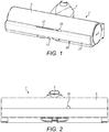
Figure 1 is a perspective view showing a cleaner head for an upright vacuum cleaner (not illustrated), with the valve being open to define a bleed path through the front of the nozzle in accordance with the present invention; -
Figure 2 is a front view of the cleaner head inFigure 1 ; -
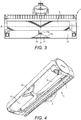
Figure 3 is a plan view of the underside of the cleaner head inFigure 1 ; -
Figure 4 is a perspective view showing the underside of the cleaner head inFigure 1 ; -
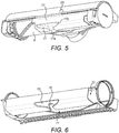
Figure 5 is a perspective view of the cleaner head shown inFigures 1 -4 , but with the soleplate removed to illustrate the position of a sliding member when the valve is open; -
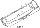
Figure 6 is a front perspective view of the soleplate omitted fromFigure 5 ; -
Figure 7 is a rear perspective view of the soleplate omitted fromFigure 5 ; -
Figure 8 is a perspective view illustrating the underside of the cleaner head shown inFigures 1-4 , but with the valve closed in accordance with the invention; and -
Figure 9 is a perspective view corresponding toFigure 8 , but with the soleplate removed to illustrate the position of the sliding member when the valve is closed. -
Figures 1-4 illustrates a suction nozzle in the form of acleaner head 1 for an upright vacuum cleaner. The remainder of the upright vacuum cleaner itself is not illustrated, and can be taken to be conventional. - The
cleaner head 1 comprises arear neck portion 3 arranged along a centerline A of thecleaner head 1 and a roughly hemi-cylindrical head section 5 which extends perpendicular to theneck portion 3 along a transverse axis B, so that thecleaner head 1 is roughly the shape of an inverted "T" (seeFigure 3 ). - The
rear neck portion 3 forms an outlet duct of thecleaner head 1 which is arranged for conventional connection to a suction inlet on the main body of the upright vacuum cleaner. This outlet duct connects to a hemi-cylindrical suction chamber 7 inside thehead section 5 which houses an agitator in the form of a drivenbrush bar 9 rotatably mounted inside thesuction chamber 7 along the transverse axis B. Thebrush bar 9 is mounted so that it protrudes through a rectangular suction opening 11 provided in a roughlyrectangular soleplate 13 forming the flat underside of the hemi-cylindrical head section 5. - In use, the
soleplate 13 engages a carpeted floor to form a working seal around the suction opening 11 and with suction applied to the outlet duct in therear portion 3 the reduced head pressure inside thesuction chamber 7 draws in dirt-laden air underneath the soleplate 13 (through the carpet fibres), through the suction opening 11, into the suction chamber 7and out through the outlet duct in therear neck portion 3. - The working seal is important for pick-up performance: an effective flow of dirt-laden air through the
suction opening 11 requires an effective working seal around thesuction opening 11. Nonetheless, it raises the problem that relatively large debris cannot pass underneath the soleplate 13: the debris is simply too large. In order therefore to provide a large debris pick-up capability, the cleaner head is provided with a valve which can be manually operated to open or close a bleed path through a relativelylarge entrance slot 15 on the front of thecleaner head 1. - The bleed path is defined by a
channel 17 formed on the underside of thesoleplate 13 which, when the valve is open as shown inFigures 1-4 , connects theentrance slot 15 on the front of the cleaner head to aninlet 19 in thefront wall 7a of thesuction chamber 7 in such manner that thesoleplate 13 also forms a working seal (against the carpet) around thechannel 17. - The
channel 17 comprises two sections: arear section 17a, having the same cross sectional area as theinlet 19 and which defines a throat having a smaller cross sectional area than theentrance slot 15; and a taperedfront section 17b, which tapers inwardly from theentrance slot 15 towards therear section 17a. - In use, large debris is admitted through the
entrance slot 15 on the front of the nozzle as the upright vacuum cleaner (and so the nozzle itself) is pushed in a forward direction. From here, the large debris is funneled through thechannel 17 and towards theinlet 19 by thetapered front section 17b, passing via therear section 17a. - The negative head pressure inside the
suction chamber 7 acts on thechannel 17 and so assists with large-debris pick-up. Nevertheless, the relatively small-arearear section 17a - defining the throat - provides a flow restriction in the bleed path to limit the proportion of the available airflow which is drawn in through the bleed path and to ensure that the majority flow is instead drawn through thesuction opening 7. This makes possible a degree of independent optimization of both large debris pick-up: by specifying the width of theentrance slot 15 so that it presents a wide 'collection' area; and also fine dust pick-up: by specifying the cross-sectional area of therear channel section 17a so that the majority of flow is directed through thesuction opening 7. - In order to maximize fine dust pick-up, the valve can be closed to close off the bleed path completely, in effect so that in use the entire flow through the
cleaner head 1 is drawn in through the suction opening 7. This provides additional flexibility for the user if large-debris pick-up is not required. - The valve is closed by means of an elongate sliding
valve member 21 which defines thechannel 17 between theentrance slot 15 and theinlet 19 and which is housed inside atransverse guide channel 23 running parallel to the transverse axis B, along the front of the cleaner head (seeFigure 6 ). The slidingvalve member 21 is thus arranged to slide between an open position shown inFigure 5 - in which thechannel 17 connects theentrance slot 15 to the inlet 19 (see alsoFigure 1 ) - and a closed position shown inFigure 9 - in which the slidingvalve member 21 obstructs the entrance slot 15 (see alsoFigure 8 ) so that the valve (and so the bleed path through the front of the nozzle) is closed. - The sliding
valve member 21 is manually operated by means of aslider handle 25 on the valve member which projects externally through anexternal guide slot 27 formed through a top part of afront bumper 27 of thehead section 5. - The
entrance slot 15 is positioned centrally on thecleaner head 1, when viewed from the front, and incorporated in a straightfront edge 29 of thecleaner head 1 which extends across the full width of thecleaner head 1. The front of the cleaner head 1- and in particular the entrance slot - can thus be brought into close proximity to a wall or skirting so that the cleaner head can provide some additional "edge pick-up" near to walls, via the bleed path through entrance slot. - In an alternative embodiment (not shown), the channel may be defined by the soleplate itself rather than by the valve sliding member. In this arrangement the sliding valve member may take the form of a sliding shutter which can be moved between an open position in which the channel is open, and a closed position, in which the shutter obstructs the channel. For example, the sliding shutter may be positioned to obstruct the entrance slot in the closed position, or alternatively to obstruct the inlet to the suction chamber in the closed position.
- It is not essential that the channel is connected to the outlet duct via the suction chamber. For example in an alternative embodiment (not shown), the channel may be connected to the outlet duct via a bypass duct which bypasses the suction chamber.
- The sliding valve member is not essential, provided that the valve member is moveable between the open and closed positions. For example, a pivoting valve member may alternatively be provided.
- The invention can similarly be implemented on other types of vacuum cleaner, for example as part of a floor tool for a cylinder vacuum cleaner or a handheld/stick vacuum cleaner.
Claims (13)
- A suction nozzle (1) for a vacuum cleaner, the suction nozzle (1) comprising a suction chamber (7), an outlet duct extending from the suction chamber (7) for connection to a vacuum source on the vacuum cleaner, a soleplate (13) for supporting the nozzle (1) on a carpeted floor, a suction opening (11) in the soleplate (13) which opens into the suction chamber (7), and a valve which can be manually operated to open or close a bleed path through the front of the nozzle (1), the bleed path being defined by a channel (17) formed on the underside of the soleplate (13) which is fluidly connected to the outlet duct, the channel (17) terminating in an entrance slot (15) on the front of the nozzle (1) for admitting debris as the suction nozzle (1) is pushed in a forward direction, characterized in that the channel (17) defines a throat (17a) downstream of the entrance slot (15), the throat (17a) having a smaller cross-sectional area than the entrance slot (15).
- A suction nozzle (1) according to claim 1, wherein the channel (17) incorporates a tapered section (17b), between the entrance slot (15) and the throat (17a), which tapers inwardly towards the throat (17a).
- A suction nozzle (1) according to claim 1 or 2, wherein the channel (17) is fluidly connected to the outlet duct via the suction chamber (7).
- A suction nozzle (1) according to claim 3, wherein the channel (17) on the underside of the soleplate (13) is merged with the suction opening (11).
- A suction nozzle (1) according to any preceding claim, in which the valve comprises a valve member (21) which is manually moveable between an open position, in which the valve is open, and a closed position, in which the valve is closed.
- A suction nozzle (1) according to claim 5, wherein at least a section of the channel (17) is formed in the valve member (21).
- A suction nozzle (1) according to claim 5 or 6, wherein the valve member (21) is manually slidable between the open position and the closed position.
- A suction nozzle (1) according to claim 7, in which the valve member (21) is housed internally inside the suction nozzle (1) and the valve member (21) is manually slidable via a slider handle (25) which projects externally through a guide slot (27) in the top of the suction nozzle (1).
- A suction nozzle (1) according to claim 7 or 8, wherein the valve member (21) is a sliding member which incorporates at least a section of the channel (17), the front wall (7a) of the suction chamber (7) comprises an inlet (19) and the valve member (21) is manually slidable between an open position in which the channel section (17) fluidly connects the entrance slot (15) to the inlet (19) in the front wall (7a) of the suction chamber (7), and a closed position in which the valve member (21) obstructs the entrance slot (15).
- A suction nozzle (1) according to any preceding claim, in which the entrance slot (15) is positioned centrally on the suction nozzle (1), viewed from the front of the nozzle (1).
- A suction nozzle (1) according to any preceding claim, in which the entrance slot (15) is incorporated in a straight front edge (29) of the cleaner head (1) extending transversely across the full width of the cleaner head (1).
- A suction nozzle (1) according to any preceding claim, in which the nozzle (1) comprises an agitator (9) inside the suction chamber (7) for engaging and agitating the carpeted floor through the suction opening (11).
- A vacuum cleaner incorporating a suction nozzle (1) according to any preceding claim.
Applications Claiming Priority (2)
| Application Number | Priority Date | Filing Date | Title |
|---|---|---|---|
| GB1503858.1A GB2536064B (en) | 2015-03-06 | 2015-03-06 | A suction nozzle for a vacuum cleaner |
| PCT/GB2016/050580 WO2016142662A1 (en) | 2015-03-06 | 2016-03-04 | A suction nozzle for a vacuum cleaner |
Publications (2)
| Publication Number | Publication Date |
|---|---|
| EP3264960A1 EP3264960A1 (en) | 2018-01-10 |
| EP3264960B1 true EP3264960B1 (en) | 2018-12-05 |
Family
ID=52998537
Family Applications (1)
| Application Number | Title | Priority Date | Filing Date |
|---|---|---|---|
| EP16709533.0A Revoked EP3264960B1 (en) | 2015-03-06 | 2016-03-04 | A suction nozzle for a vacuum cleaner |
Country Status (6)
| Country | Link |
|---|---|
| US (1) | US9826869B2 (en) |
| EP (1) | EP3264960B1 (en) |
| JP (1) | JP2016163707A (en) |
| CN (1) | CN105935274B (en) |
| GB (1) | GB2536064B (en) |
| WO (1) | WO2016142662A1 (en) |
Cited By (1)
| Publication number | Priority date | Publication date | Assignee | Title |
|---|---|---|---|---|
| WO2021141223A1 (en) * | 2020-01-09 | 2021-07-15 | 엘지전자 주식회사 | Cleaning module and cleaner comprising same |
Families Citing this family (9)
| Publication number | Priority date | Publication date | Assignee | Title |
|---|---|---|---|---|
| WO2016123190A1 (en) * | 2015-01-28 | 2016-08-04 | Techtronic Industries Co. Ltd | Surface cleaning head with a valve assembly |
| EP3429450A1 (en) * | 2016-01-27 | 2019-01-23 | China Manufacturing and Brokerage, Inc. | Vacuum cleaner power nozzle having selectively introduced secondary airflow for operation on carpeted surfaces |
| KR101935946B1 (en) * | 2017-01-19 | 2019-01-07 | 엘지전자 주식회사 | Cleaner |
| KR102448087B1 (en) * | 2017-01-19 | 2022-09-28 | 엘지전자 주식회사 | Cleaner |
| GB2562524B (en) * | 2017-05-18 | 2019-10-02 | Dyson Technology Ltd | Suction nozzle |
| GB2571535A (en) * | 2018-02-28 | 2019-09-04 | Dyson Technology Ltd | A cleaner head |
| US11291345B2 (en) | 2018-08-27 | 2022-04-05 | Techtronic Floor Care Technology Limited | Floor cleaner |
| DE102019103651A1 (en) | 2019-02-13 | 2020-08-13 | Alfred Kärcher SE & Co. KG | Floor nozzle for a cleaning device with suction function, cleaning device and method for vacuuming a floor area |
| US11033162B1 (en) * | 2019-12-12 | 2021-06-15 | Zenith Technologies, Llc | Vacuum cleaner having flexible vent members |
Citations (10)
| Publication number | Priority date | Publication date | Assignee | Title |
|---|---|---|---|---|
| DE862654C (en) | 1950-09-06 | 1953-01-12 | Siemens Ag | Vacuum cleaner nozzles, in particular articulated nozzles |
| JPS57145354U (en) | 1981-03-06 | 1982-09-13 | ||
| JPH01181826A (en) | 1988-01-14 | 1989-07-19 | Tokyo Electric Co Ltd | Sucking port body for vacuum cleaner |
| JPH04197224A (en) | 1990-11-28 | 1992-07-16 | Tokyo Electric Co Ltd | Suction port body of vacuum cleaner |
| JPH0521852U (en) | 1991-08-30 | 1993-03-23 | 清二 北村 | Floor suction of vacuum cleaner with corner cleaning function |
| US20020133902A1 (en) | 2001-03-20 | 2002-09-26 | Vanderlinden Roger P. | Large area surface cleaning tool |
| CA2376220A1 (en) | 2002-03-20 | 2003-09-20 | Roger Vanderlinden | Large area surface cleaning tool |
| DE102004031373A1 (en) | 2003-12-05 | 2005-07-07 | Samsung Gwangju Electronics Co. Ltd. | Vacuum cleaner and suction connection arrangement of a vacuum cleaner |
| DE102004005144A1 (en) | 2004-02-03 | 2005-08-18 | Vorwerk & Co. Interholding Gmbh | A method for improving the action of a vacuum cleaner nozzle on carpeted surfaces has a sliding shoe in front of the rotating brush which withdraws in the backward direction |
| DE102008012889A1 (en) | 2008-03-06 | 2009-09-10 | Wessel-Werk Gmbh | Suction nozzle for vacuum cleaner |
Family Cites Families (20)
| Publication number | Priority date | Publication date | Assignee | Title |
|---|---|---|---|---|
| JPS56122448U (en) * | 1980-02-20 | 1981-09-18 | ||
| JPS57145354A (en) | 1980-11-21 | 1982-09-08 | Gao Ges Automation Org | Carrier element for ic module |
| JPS6033948A (en) | 1983-08-02 | 1985-02-21 | 松下電器産業株式会社 | Water emitting apparatus with shower |
| JPH0630129Y2 (en) | 1987-01-06 | 1994-08-17 | シャープ株式会社 | Vacuum cleaner suction tool |
| JPH06102060B2 (en) | 1987-01-20 | 1994-12-14 | 三洋電機株式会社 | Vacuum cleaner floor suction tool |
| DE3740635A1 (en) | 1987-12-01 | 1989-06-15 | Bayer Ag | RUTILE MIXED-PHASE PIGMENTS WITH IMPROVED COLORISTICS |
| JP2639970B2 (en) | 1988-07-07 | 1997-08-13 | 三洋電機株式会社 | Floor suction device |
| JPH0910147A (en) | 1995-06-28 | 1997-01-14 | Hitachi Ltd | Vacuum cleaner |
| DE29914329U1 (en) | 1999-08-16 | 2000-12-28 | Faun Viatec Gmbh | Suction nozzle |
| KR100555209B1 (en) | 1999-10-19 | 2006-03-03 | 삼성광주전자 주식회사 | Brush for vacuum cleaner |
| JP4612156B2 (en) | 2000-06-23 | 2011-01-12 | 株式会社東芝 | Vacuum cleaner and its suction port |
| JP3731725B2 (en) | 2000-08-31 | 2006-01-05 | 東芝テック株式会社 | Vacuum cleaner and its suction port |
| US6584640B2 (en) | 2001-03-20 | 2003-07-01 | Roger P. Vanderlinden | Large area surface cleaning tool for suctioning both dust and debris |
| JP2003144356A (en) * | 2001-11-13 | 2003-05-20 | Toshiba Tec Corp | Sucking port body for vacuum cleaner and vacuum cleaner |
| GB2383257B (en) * | 2001-12-21 | 2005-08-10 | Dyson Ltd | Cleaner head for a vacuum cleaner |
| KR20030093625A (en) * | 2002-06-04 | 2003-12-11 | 삼성광주전자 주식회사 | A Brush of vacuum cleaner with floor cloth using a Turbine |
| KR100642076B1 (en) * | 2004-07-01 | 2006-11-10 | 삼성광주전자 주식회사 | A suction port assembly and a vacuum cleaner having the same |
| GB2419278B (en) * | 2006-01-19 | 2007-01-10 | Grey Technology Ltd | Suction head for a vacuum cleaner |
| GB201003601D0 (en) * | 2010-03-04 | 2010-04-21 | Dyson Technology Ltd | A vacuum cleaning appliance |
| FR2980353B1 (en) * | 2011-09-28 | 2013-10-25 | Seb Sa | VACUUM SUCKER |
-
2015
- 2015-03-06 GB GB1503858.1A patent/GB2536064B/en not_active Expired - Fee Related
-
2016
- 2016-03-04 US US15/061,172 patent/US9826869B2/en not_active Expired - Fee Related
- 2016-03-04 WO PCT/GB2016/050580 patent/WO2016142662A1/en active Application Filing
- 2016-03-04 EP EP16709533.0A patent/EP3264960B1/en not_active Revoked
- 2016-03-07 CN CN201610127663.9A patent/CN105935274B/en not_active Expired - Fee Related
- 2016-03-07 JP JP2016043115A patent/JP2016163707A/en active Pending
Patent Citations (10)
| Publication number | Priority date | Publication date | Assignee | Title |
|---|---|---|---|---|
| DE862654C (en) | 1950-09-06 | 1953-01-12 | Siemens Ag | Vacuum cleaner nozzles, in particular articulated nozzles |
| JPS57145354U (en) | 1981-03-06 | 1982-09-13 | ||
| JPH01181826A (en) | 1988-01-14 | 1989-07-19 | Tokyo Electric Co Ltd | Sucking port body for vacuum cleaner |
| JPH04197224A (en) | 1990-11-28 | 1992-07-16 | Tokyo Electric Co Ltd | Suction port body of vacuum cleaner |
| JPH0521852U (en) | 1991-08-30 | 1993-03-23 | 清二 北村 | Floor suction of vacuum cleaner with corner cleaning function |
| US20020133902A1 (en) | 2001-03-20 | 2002-09-26 | Vanderlinden Roger P. | Large area surface cleaning tool |
| CA2376220A1 (en) | 2002-03-20 | 2003-09-20 | Roger Vanderlinden | Large area surface cleaning tool |
| DE102004031373A1 (en) | 2003-12-05 | 2005-07-07 | Samsung Gwangju Electronics Co. Ltd. | Vacuum cleaner and suction connection arrangement of a vacuum cleaner |
| DE102004005144A1 (en) | 2004-02-03 | 2005-08-18 | Vorwerk & Co. Interholding Gmbh | A method for improving the action of a vacuum cleaner nozzle on carpeted surfaces has a sliding shoe in front of the rotating brush which withdraws in the backward direction |
| DE102008012889A1 (en) | 2008-03-06 | 2009-09-10 | Wessel-Werk Gmbh | Suction nozzle for vacuum cleaner |
Cited By (3)
| Publication number | Priority date | Publication date | Assignee | Title |
|---|---|---|---|---|
| WO2021141223A1 (en) * | 2020-01-09 | 2021-07-15 | 엘지전자 주식회사 | Cleaning module and cleaner comprising same |
| CN115003204A (en) * | 2020-01-09 | 2022-09-02 | Lg电子株式会社 | Cleaning module and dust collector comprising same |
| CN115003204B (en) * | 2020-01-09 | 2023-12-08 | Lg电子株式会社 | Cleaning module and dust collector comprising same |
Also Published As
| Publication number | Publication date |
|---|---|
| GB201503858D0 (en) | 2015-04-22 |
| WO2016142662A1 (en) | 2016-09-15 |
| CN105935274B (en) | 2018-09-25 |
| US20160256024A1 (en) | 2016-09-08 |
| US9826869B2 (en) | 2017-11-28 |
| CN105935274A (en) | 2016-09-14 |
| GB2536064B (en) | 2017-06-07 |
| EP3264960A1 (en) | 2018-01-10 |
| JP2016163707A (en) | 2016-09-08 |
| GB2536064A (en) | 2016-09-07 |
Similar Documents
| Publication | Publication Date | Title |
|---|---|---|
| EP3264960B1 (en) | A suction nozzle for a vacuum cleaner | |
| EP2453779B1 (en) | A surface treating head | |
| US8468647B2 (en) | Surface treating head | |
| US8424157B2 (en) | Tool for a surface treating appliance | |
| EP2048999B1 (en) | An attachment for a cleaning appliance | |
| US20130047370A1 (en) | Auxiliary suction nozzle and port for vacuum cleaner | |
| US6539577B1 (en) | Vacuum cleaner suction tool with partition defining air current dust pickup path | |
| US9737183B2 (en) | Vacuum cleaner | |
| US10667660B2 (en) | Suction nozzle | |
| KR20090050792A (en) | Vacuum cleaner | |
| TWI615121B (en) | a nozzle for absorbing coarse particles and fine dust | |
| US9149169B2 (en) | Dual suction vacuum apparatuses and methods for use | |
| KR100688614B1 (en) | Suction brush of vacuum cleaner | |
| US20020133902A1 (en) | Large area surface cleaning tool | |
| CN211722986U (en) | Ground-engaging suction nozzle for a suction device for cleaning floor surfaces | |
| EP3010385B1 (en) | Nozzle for a vacuum cleaner and vacuum cleaner | |
| CN112190176A (en) | Ground-engaging suction nozzle for a suction device for cleaning and caring for floor surfaces |
Legal Events
| Date | Code | Title | Description |
|---|---|---|---|
| STAA | Information on the status of an ep patent application or granted ep patent |
Free format text: STATUS: THE INTERNATIONAL PUBLICATION HAS BEEN MADE |
|
| PUAI | Public reference made under article 153(3) epc to a published international application that has entered the european phase |
Free format text: ORIGINAL CODE: 0009012 |
|
| STAA | Information on the status of an ep patent application or granted ep patent |
Free format text: STATUS: REQUEST FOR EXAMINATION WAS MADE |
|
| 17P | Request for examination filed |
Effective date: 20170919 |
|
| AK | Designated contracting states |
Kind code of ref document: A1 Designated state(s): AL AT BE BG CH CY CZ DE DK EE ES FI FR GB GR HR HU IE IS IT LI LT LU LV MC MK MT NL NO PL PT RO RS SE SI SK SM TR |
|
| AX | Request for extension of the european patent |
Extension state: BA ME |
|
| DAV | Request for validation of the european patent (deleted) | ||
| DAX | Request for extension of the european patent (deleted) | ||
| GRAP | Despatch of communication of intention to grant a patent |
Free format text: ORIGINAL CODE: EPIDOSNIGR1 |
|
| STAA | Information on the status of an ep patent application or granted ep patent |
Free format text: STATUS: GRANT OF PATENT IS INTENDED |
|
| INTG | Intention to grant announced |
Effective date: 20180814 |
|
| GRAS | Grant fee paid |
Free format text: ORIGINAL CODE: EPIDOSNIGR3 |
|
| GRAA | (expected) grant |
Free format text: ORIGINAL CODE: 0009210 |
|
| STAA | Information on the status of an ep patent application or granted ep patent |
Free format text: STATUS: THE PATENT HAS BEEN GRANTED |
|
| AK | Designated contracting states |
Kind code of ref document: B1 Designated state(s): AL AT BE BG CH CY CZ DE DK EE ES FI FR GB GR HR HU IE IS IT LI LT LU LV MC MK MT NL NO PL PT RO RS SE SI SK SM TR |
|
| REG | Reference to a national code |
Ref country code: GB Ref legal event code: FG4D |
|
| REG | Reference to a national code |
Ref country code: CH Ref legal event code: EP |
|
| REG | Reference to a national code |
Ref country code: AT Ref legal event code: REF Ref document number: 1071993 Country of ref document: AT Kind code of ref document: T Effective date: 20181215 |
|
| REG | Reference to a national code |
Ref country code: IE Ref legal event code: FG4D |
|
| REG | Reference to a national code |
Ref country code: DE Ref legal event code: R096 Ref document number: 602016007862 Country of ref document: DE |
|
| REG | Reference to a national code |
Ref country code: NL Ref legal event code: MP Effective date: 20181205 |
|
| REG | Reference to a national code |
Ref country code: AT Ref legal event code: MK05 Ref document number: 1071993 Country of ref document: AT Kind code of ref document: T Effective date: 20181205 |
|
| REG | Reference to a national code |
Ref country code: LT Ref legal event code: MG4D |
|
| PG25 | Lapsed in a contracting state [announced via postgrant information from national office to epo] |
Ref country code: FI Free format text: LAPSE BECAUSE OF FAILURE TO SUBMIT A TRANSLATION OF THE DESCRIPTION OR TO PAY THE FEE WITHIN THE PRESCRIBED TIME-LIMIT Effective date: 20181205 Ref country code: NO Free format text: LAPSE BECAUSE OF FAILURE TO SUBMIT A TRANSLATION OF THE DESCRIPTION OR TO PAY THE FEE WITHIN THE PRESCRIBED TIME-LIMIT Effective date: 20190305 Ref country code: AT Free format text: LAPSE BECAUSE OF FAILURE TO SUBMIT A TRANSLATION OF THE DESCRIPTION OR TO PAY THE FEE WITHIN THE PRESCRIBED TIME-LIMIT Effective date: 20181205 Ref country code: ES Free format text: LAPSE BECAUSE OF FAILURE TO SUBMIT A TRANSLATION OF THE DESCRIPTION OR TO PAY THE FEE WITHIN THE PRESCRIBED TIME-LIMIT Effective date: 20181205 Ref country code: LV Free format text: LAPSE BECAUSE OF FAILURE TO SUBMIT A TRANSLATION OF THE DESCRIPTION OR TO PAY THE FEE WITHIN THE PRESCRIBED TIME-LIMIT Effective date: 20181205 Ref country code: HR Free format text: LAPSE BECAUSE OF FAILURE TO SUBMIT A TRANSLATION OF THE DESCRIPTION OR TO PAY THE FEE WITHIN THE PRESCRIBED TIME-LIMIT Effective date: 20181205 Ref country code: LT Free format text: LAPSE BECAUSE OF FAILURE TO SUBMIT A TRANSLATION OF THE DESCRIPTION OR TO PAY THE FEE WITHIN THE PRESCRIBED TIME-LIMIT Effective date: 20181205 Ref country code: BG Free format text: LAPSE BECAUSE OF FAILURE TO SUBMIT A TRANSLATION OF THE DESCRIPTION OR TO PAY THE FEE WITHIN THE PRESCRIBED TIME-LIMIT Effective date: 20190305 |
|
| PGFP | Annual fee paid to national office [announced via postgrant information from national office to epo] |
Ref country code: DE Payment date: 20190327 Year of fee payment: 4 Ref country code: FR Payment date: 20190325 Year of fee payment: 4 |
|
| PG25 | Lapsed in a contracting state [announced via postgrant information from national office to epo] |
Ref country code: AL Free format text: LAPSE BECAUSE OF FAILURE TO SUBMIT A TRANSLATION OF THE DESCRIPTION OR TO PAY THE FEE WITHIN THE PRESCRIBED TIME-LIMIT Effective date: 20181205 Ref country code: RS Free format text: LAPSE BECAUSE OF FAILURE TO SUBMIT A TRANSLATION OF THE DESCRIPTION OR TO PAY THE FEE WITHIN THE PRESCRIBED TIME-LIMIT Effective date: 20181205 Ref country code: GR Free format text: LAPSE BECAUSE OF FAILURE TO SUBMIT A TRANSLATION OF THE DESCRIPTION OR TO PAY THE FEE WITHIN THE PRESCRIBED TIME-LIMIT Effective date: 20190306 Ref country code: SE Free format text: LAPSE BECAUSE OF FAILURE TO SUBMIT A TRANSLATION OF THE DESCRIPTION OR TO PAY THE FEE WITHIN THE PRESCRIBED TIME-LIMIT Effective date: 20181205 |
|
| PG25 | Lapsed in a contracting state [announced via postgrant information from national office to epo] |
Ref country code: NL Free format text: LAPSE BECAUSE OF FAILURE TO SUBMIT A TRANSLATION OF THE DESCRIPTION OR TO PAY THE FEE WITHIN THE PRESCRIBED TIME-LIMIT Effective date: 20181205 |
|
| PG25 | Lapsed in a contracting state [announced via postgrant information from national office to epo] |
Ref country code: CZ Free format text: LAPSE BECAUSE OF FAILURE TO SUBMIT A TRANSLATION OF THE DESCRIPTION OR TO PAY THE FEE WITHIN THE PRESCRIBED TIME-LIMIT Effective date: 20181205 Ref country code: PL Free format text: LAPSE BECAUSE OF FAILURE TO SUBMIT A TRANSLATION OF THE DESCRIPTION OR TO PAY THE FEE WITHIN THE PRESCRIBED TIME-LIMIT Effective date: 20181205 Ref country code: PT Free format text: LAPSE BECAUSE OF FAILURE TO SUBMIT A TRANSLATION OF THE DESCRIPTION OR TO PAY THE FEE WITHIN THE PRESCRIBED TIME-LIMIT Effective date: 20190405 Ref country code: IT Free format text: LAPSE BECAUSE OF FAILURE TO SUBMIT A TRANSLATION OF THE DESCRIPTION OR TO PAY THE FEE WITHIN THE PRESCRIBED TIME-LIMIT Effective date: 20181205 |
|
| PG25 | Lapsed in a contracting state [announced via postgrant information from national office to epo] |
Ref country code: SM Free format text: LAPSE BECAUSE OF FAILURE TO SUBMIT A TRANSLATION OF THE DESCRIPTION OR TO PAY THE FEE WITHIN THE PRESCRIBED TIME-LIMIT Effective date: 20181205 Ref country code: EE Free format text: LAPSE BECAUSE OF FAILURE TO SUBMIT A TRANSLATION OF THE DESCRIPTION OR TO PAY THE FEE WITHIN THE PRESCRIBED TIME-LIMIT Effective date: 20181205 Ref country code: RO Free format text: LAPSE BECAUSE OF FAILURE TO SUBMIT A TRANSLATION OF THE DESCRIPTION OR TO PAY THE FEE WITHIN THE PRESCRIBED TIME-LIMIT Effective date: 20181205 Ref country code: SK Free format text: LAPSE BECAUSE OF FAILURE TO SUBMIT A TRANSLATION OF THE DESCRIPTION OR TO PAY THE FEE WITHIN THE PRESCRIBED TIME-LIMIT Effective date: 20181205 Ref country code: IS Free format text: LAPSE BECAUSE OF FAILURE TO SUBMIT A TRANSLATION OF THE DESCRIPTION OR TO PAY THE FEE WITHIN THE PRESCRIBED TIME-LIMIT Effective date: 20190405 |
|
| REG | Reference to a national code |
Ref country code: DE Ref legal event code: R026 Ref document number: 602016007862 Country of ref document: DE |
|
| PLBI | Opposition filed |
Free format text: ORIGINAL CODE: 0009260 |
|
| PLAX | Notice of opposition and request to file observation + time limit sent |
Free format text: ORIGINAL CODE: EPIDOSNOBS2 |
|
| 26 | Opposition filed |
Opponent name: VORWERK & CO. INTERHOLDING GMBH Effective date: 20190902 |
|
| PG25 | Lapsed in a contracting state [announced via postgrant information from national office to epo] |
Ref country code: DK Free format text: LAPSE BECAUSE OF FAILURE TO SUBMIT A TRANSLATION OF THE DESCRIPTION OR TO PAY THE FEE WITHIN THE PRESCRIBED TIME-LIMIT Effective date: 20181205 Ref country code: MC Free format text: LAPSE BECAUSE OF FAILURE TO SUBMIT A TRANSLATION OF THE DESCRIPTION OR TO PAY THE FEE WITHIN THE PRESCRIBED TIME-LIMIT Effective date: 20181205 |
|
| REG | Reference to a national code |
Ref country code: CH Ref legal event code: PL |
|
| PG25 | Lapsed in a contracting state [announced via postgrant information from national office to epo] |
Ref country code: LU Free format text: LAPSE BECAUSE OF NON-PAYMENT OF DUE FEES Effective date: 20190304 |
|
| REG | Reference to a national code |
Ref country code: BE Ref legal event code: MM Effective date: 20190331 |
|
| PG25 | Lapsed in a contracting state [announced via postgrant information from national office to epo] |
Ref country code: LI Free format text: LAPSE BECAUSE OF NON-PAYMENT OF DUE FEES Effective date: 20190331 Ref country code: CH Free format text: LAPSE BECAUSE OF NON-PAYMENT OF DUE FEES Effective date: 20190331 Ref country code: IE Free format text: LAPSE BECAUSE OF NON-PAYMENT OF DUE FEES Effective date: 20190304 |
|
| PLBB | Reply of patent proprietor to notice(s) of opposition received |
Free format text: ORIGINAL CODE: EPIDOSNOBS3 |
|
| RDAF | Communication despatched that patent is revoked |
Free format text: ORIGINAL CODE: EPIDOSNREV1 |
|
| REG | Reference to a national code |
Ref country code: DE Ref legal event code: R064 Ref document number: 602016007862 Country of ref document: DE Ref country code: DE Ref legal event code: R103 Ref document number: 602016007862 Country of ref document: DE |
|
| PG25 | Lapsed in a contracting state [announced via postgrant information from national office to epo] |
Ref country code: BE Free format text: LAPSE BECAUSE OF NON-PAYMENT OF DUE FEES Effective date: 20190331 |
|
| PG25 | Lapsed in a contracting state [announced via postgrant information from national office to epo] |
Ref country code: TR Free format text: LAPSE BECAUSE OF FAILURE TO SUBMIT A TRANSLATION OF THE DESCRIPTION OR TO PAY THE FEE WITHIN THE PRESCRIBED TIME-LIMIT Effective date: 20181205 |
|
| PG25 | Lapsed in a contracting state [announced via postgrant information from national office to epo] |
Ref country code: MT Free format text: LAPSE BECAUSE OF NON-PAYMENT OF DUE FEES Effective date: 20190304 |
|
| RDAG | Patent revoked |
Free format text: ORIGINAL CODE: 0009271 |
|
| STAA | Information on the status of an ep patent application or granted ep patent |
Free format text: STATUS: PATENT REVOKED |
|
| REG | Reference to a national code |
Ref country code: FI Ref legal event code: MGE |
|
| 27W | Patent revoked |
Effective date: 20200223 |
|
| GBPR | Gb: patent revoked under art. 102 of the ep convention designating the uk as contracting state |
Effective date: 20200223 |
|
| PG25 | Lapsed in a contracting state [announced via postgrant information from national office to epo] |
Ref country code: HU Free format text: LAPSE BECAUSE OF FAILURE TO SUBMIT A TRANSLATION OF THE DESCRIPTION OR TO PAY THE FEE WITHIN THE PRESCRIBED TIME-LIMIT; INVALID AB INITIO Effective date: 20160304 |
|
| PG25 | Lapsed in a contracting state [announced via postgrant information from national office to epo] |
Ref country code: SI Free format text: LAPSE BECAUSE OF FAILURE TO SUBMIT A TRANSLATION OF THE DESCRIPTION OR TO PAY THE FEE WITHIN THE PRESCRIBED TIME-LIMIT Effective date: 20181205 |
|
| PG25 | Lapsed in a contracting state [announced via postgrant information from national office to epo] |
Ref country code: MK Free format text: LAPSE BECAUSE OF FAILURE TO SUBMIT A TRANSLATION OF THE DESCRIPTION OR TO PAY THE FEE WITHIN THE PRESCRIBED TIME-LIMIT Effective date: 20181205 |