EP3264251B1 - Generation of a color of an object displayed on a gui - Google Patents
Generation of a color of an object displayed on a gui Download PDFInfo
- Publication number
- EP3264251B1 EP3264251B1 EP16305798.7A EP16305798A EP3264251B1 EP 3264251 B1 EP3264251 B1 EP 3264251B1 EP 16305798 A EP16305798 A EP 16305798A EP 3264251 B1 EP3264251 B1 EP 3264251B1
- Authority
- EP
- European Patent Office
- Prior art keywords
- color
- user
- icon
- user interaction
- touch
- Prior art date
- Legal status (The legal status is an assumption and is not a legal conclusion. Google has not performed a legal analysis and makes no representation as to the accuracy of the status listed.)
- Active
Links
Images


Classifications
-
- G—PHYSICS
- G06—COMPUTING; CALCULATING OR COUNTING
- G06F—ELECTRIC DIGITAL DATA PROCESSING
- G06F3/00—Input arrangements for transferring data to be processed into a form capable of being handled by the computer; Output arrangements for transferring data from processing unit to output unit, e.g. interface arrangements
- G06F3/01—Input arrangements or combined input and output arrangements for interaction between user and computer
- G06F3/048—Interaction techniques based on graphical user interfaces [GUI]
- G06F3/0484—Interaction techniques based on graphical user interfaces [GUI] for the control of specific functions or operations, e.g. selecting or manipulating an object, an image or a displayed text element, setting a parameter value or selecting a range
- G06F3/04847—Interaction techniques to control parameter settings, e.g. interaction with sliders or dials
-
- G—PHYSICS
- G06—COMPUTING; CALCULATING OR COUNTING
- G06F—ELECTRIC DIGITAL DATA PROCESSING
- G06F3/00—Input arrangements for transferring data to be processed into a form capable of being handled by the computer; Output arrangements for transferring data from processing unit to output unit, e.g. interface arrangements
- G06F3/01—Input arrangements or combined input and output arrangements for interaction between user and computer
- G06F3/048—Interaction techniques based on graphical user interfaces [GUI]
- G06F3/0481—Interaction techniques based on graphical user interfaces [GUI] based on specific properties of the displayed interaction object or a metaphor-based environment, e.g. interaction with desktop elements like windows or icons, or assisted by a cursor's changing behaviour or appearance
- G06F3/04817—Interaction techniques based on graphical user interfaces [GUI] based on specific properties of the displayed interaction object or a metaphor-based environment, e.g. interaction with desktop elements like windows or icons, or assisted by a cursor's changing behaviour or appearance using icons
-
- G—PHYSICS
- G06—COMPUTING; CALCULATING OR COUNTING
- G06F—ELECTRIC DIGITAL DATA PROCESSING
- G06F3/00—Input arrangements for transferring data to be processed into a form capable of being handled by the computer; Output arrangements for transferring data from processing unit to output unit, e.g. interface arrangements
- G06F3/01—Input arrangements or combined input and output arrangements for interaction between user and computer
- G06F3/048—Interaction techniques based on graphical user interfaces [GUI]
- G06F3/0487—Interaction techniques based on graphical user interfaces [GUI] using specific features provided by the input device, e.g. functions controlled by the rotation of a mouse with dual sensing arrangements, or of the nature of the input device, e.g. tap gestures based on pressure sensed by a digitiser
- G06F3/0488—Interaction techniques based on graphical user interfaces [GUI] using specific features provided by the input device, e.g. functions controlled by the rotation of a mouse with dual sensing arrangements, or of the nature of the input device, e.g. tap gestures based on pressure sensed by a digitiser using a touch-screen or digitiser, e.g. input of commands through traced gestures
- G06F3/04883—Interaction techniques based on graphical user interfaces [GUI] using specific features provided by the input device, e.g. functions controlled by the rotation of a mouse with dual sensing arrangements, or of the nature of the input device, e.g. tap gestures based on pressure sensed by a digitiser using a touch-screen or digitiser, e.g. input of commands through traced gestures for inputting data by handwriting, e.g. gesture or text
-
- G—PHYSICS
- G06—COMPUTING; CALCULATING OR COUNTING
- G06F—ELECTRIC DIGITAL DATA PROCESSING
- G06F30/00—Computer-aided design [CAD]
-
- G—PHYSICS
- G06—COMPUTING; CALCULATING OR COUNTING
- G06T—IMAGE DATA PROCESSING OR GENERATION, IN GENERAL
- G06T11/00—2D [Two Dimensional] image generation
- G06T11/001—Texturing; Colouring; Generation of texture or colour
-
- G—PHYSICS
- G06—COMPUTING; CALCULATING OR COUNTING
- G06F—ELECTRIC DIGITAL DATA PROCESSING
- G06F2119/00—Details relating to the type or aim of the analysis or the optimisation
- G06F2119/18—Manufacturability analysis or optimisation for manufacturability
-
- G—PHYSICS
- G06—COMPUTING; CALCULATING OR COUNTING
- G06F—ELECTRIC DIGITAL DATA PROCESSING
- G06F3/00—Input arrangements for transferring data to be processed into a form capable of being handled by the computer; Output arrangements for transferring data from processing unit to output unit, e.g. interface arrangements
- G06F3/01—Input arrangements or combined input and output arrangements for interaction between user and computer
- G06F3/048—Interaction techniques based on graphical user interfaces [GUI]
- G06F3/0484—Interaction techniques based on graphical user interfaces [GUI] for the control of specific functions or operations, e.g. selecting or manipulating an object, an image or a displayed text element, setting a parameter value or selecting a range
- G06F3/04842—Selection of displayed objects or displayed text elements
-
- G—PHYSICS
- G06—COMPUTING; CALCULATING OR COUNTING
- G06T—IMAGE DATA PROCESSING OR GENERATION, IN GENERAL
- G06T2200/00—Indexing scheme for image data processing or generation, in general
- G06T2200/24—Indexing scheme for image data processing or generation, in general involving graphical user interfaces [GUIs]
Definitions
- the invention relates to the field of computer programs and systems, and more specifically to a method, system and program for generating a color of an object displayed on a graphical user interface.
- CAD Computer-Aided Design
- CAE Computer-Aided Engineering
- CAM Computer-Aided Manufacturing
- the graphical user interface plays an important role as regards the efficiency of the technique.
- PLM refers to a business strategy that helps companies to share product data, apply common processes, and leverage corporate knowledge for the development of products from conception to the end of their life, across the concept of extended enterprise.
- the PLM solutions provided by Dassault Systèmes (under the trademarks CATIA, ENOVIA and DELMIA) provide an Engineering Hub, which organizes product engineering knowledge, a Manufacturing Hub, which manages manufacturing engineering knowledge, and an Enterprise Hub which enables enterprise integrations and connections into both the Engineering and Manufacturing Hubs. All together the system delivers an open object model linking products, processes, resources to enable dynamic, knowledge-based product creation and decision support that drives optimized product definition, manufacturing preparation, production and service.
- a color picker contains graphical tools such as buttons, sliders, entry fields... for modifying color properties, and therefore for modifying a color. These color pickers can be accessed thanks to a separated panel, or a contextual menu, that appears after an action on the button.
- the known color pickers suffer several drawbacks.
- the number of user interactions required for configuring and obtaining the right color can be important, notably when customizing the parameters, while reducing the number of interactions for configuring a color is critical in touch-sensitive environments, e.g. on the touch-sensitive screen of a tablet.
- the known color pickers use a non-negligible space on the graphical user interface, and thus on the screen, due to the multiple commands display.
- touch-sensitive devices have a display with a limited size, e.g. a tablet.
- the manipulations for using the commands are not adapted to touch-sensitive environments, and many input errors may occur when configuring parameters of a color. The user has to trigger several times a same command for performing all the adjustment of all the parameters.
- Document WO 2013/133905 A1 discloses a computer program for adjusting color values of an image represented in a color space.
- the image includes a set of pixels. Each pixel has a set of color values.
- the computer program receives a user input on a user interface item for adjusting color values of an image that are associated with a type of content.
- the computer program identifies a subset of pixels having color values that fall within a range of color values associated with the type of content.
- Some embodiments implement a set of on-image UI controls as direction dependent UI controls.
- the application displays a directional arrow for each UI control in order to guide the user to initiate the color adjustment operation associated with the UI control.
- the user initiates different color adjustment operations by providing different directional inputs. Based on the direction of the directional input, the application performs a particular color adjustment on the image, including adjustments to the type of content and adjustments to the entire image.
- Document US 2013/0326381 A1 discloses a touch sensitive device running a digital art program that provides a user interface, including elements comprising a palette and art tools.
- the palette includes a mixing area and paint wells.
- the art tools include selectable brushes by which a user interacts to add paint from the paint wells to the mixing area and mix the paint into a mixed color paint.
- the user interface also includes a drawing surface with which the user interacts to add paint from the paint wells via a selected brush, and/or add paint from the mixing area.
- the invention relates to a computer-implemented method as defined in the appended independent claim 1.
- Preferred embodiments of the method are defined in the appended dependent claims 2-9.
- the invention further relates to a computer program comprising instructions for performing the method and to a computer readable storage medium having recorded thereon the computer program.
- the invention further relates to a system comprising a processor coupled to a memory and a graphical user interface, the memory having recorded thereon the computer program.
- a computer-implemented method for generating a color of an object displayed on a graphical user interface improves the configuration of a colour on a touch sensitive display or at least with a touch sensitive haptic device.
- the invention makes easier the modification of the color properties on a dimensional geometry on a 3D modeled object, or on 2D object, and more generally on any object displayed by a computer program such as a CAD system, a graphics editor program.
- This invention allows the user to customize the color properties in one hold, e.g. without lifting the finger from a touch-sensitive display.
- the user can modify color, brightness and opacity in a same action.
- the user can also merge different colors in order to obtain a new hybrid color.
- the method is computer-implemented. This means that the steps (or substantially all the steps) of the method are executed by at least one computer, or any system alike. Thus, steps of the method are performed by the computer, possibly fully automatically, or, semi-automatically. In examples, the triggering of at least some of the steps of the method may be performed through user-computer interaction.
- the level of user-computer interaction required may depend on the level of automatism foreseen and put in balance with the need to implement user's wishes. In examples, this level may be user-defined and/or pre-defined.
- the modification of a value of a parameter of a color is performed with a user interaction that may be a touch comprising a slide; the user may touch a touch-sensitive display with one of their finger and then slide the finger from the location of the touch in order to modify the parameter value.
- Touch, tap, and slide are examples of user interactions a user can carry out for performing the method of the invention.
- Atypical example of computer-implementation of the method is to perform the method with a system adapted for this purpose.
- the system may comprise a processor coupled to a memory and a graphical user interface (GUI), the memory having recorded thereon a computer program comprising instructions for performing the method.
- the memory may also store a database.
- the memory is any hardware adapted for such storage, possibly comprising several physical distinct parts (e.g. one for the program, and possibly one for the database).
- the system also provides a touch sensitive haptic device that may be, but is not limited to, a touch sensitive screen, a pen display, a pen tablet. The touch sensitive screen or the pen display can display the graphical user interface.
- the generated color can be applied on an object that may be, but is not limited to, a 2D object, a 3D object (the 2D or 3D object can be a modeled object), a picture,... More generally, the generated color can be applied on any kind of object that is rendered or displayed on a graphical user interface. Applying the generated color means that the rendering of an object is modified: the object (or at least a part of the object) is rendered with the generated color.
- the object to color can be stored on a database.
- database it is meant any collection of data (i.e. information) organized for search and retrieval (e.g. a relational database, e.g. based on a predetermined structured language, e.g. SQL).
- search and retrieval e.g. a relational database, e.g. based on a predetermined structured language, e.g. SQL.
- databases are indeed structured to facilitate storage, retrieval, modification, and deletion of data in conjunction with various data-processing operations.
- the database may consist of a file or set of files that can be broken down into records, each of which consists of one or more fields. Fields are the basic units of data storage. Users may retrieve data primarily through queries. Using keywords and sorting commands, users can rapidly search, rearrange, group, and select the field in many records to retrieve or create reports on particular aggregates of data according to the rules of the database management system being used.
- the method generally manipulates objects.
- An object is defined by data stored e.g. in the database.
- the term "object” designates the data itself.
- the objects may be defined by different kinds of data.
- the system may indeed be any combination of a CAD system, a CAE system, a CAM system, a PDM system and/or a PLM system.
- the system may execute any application suitable for rendering an object, such as a graphic editor.
- objects are defined by corresponding data.
- these systems are not exclusive one of the other, as a modeled object may be defined by data corresponding to any combination of these systems.
- CAD system it is additionally meant any system adapted at least for designing a modeled object on the basis of a graphical representation of the modeled object, such as CATIA.
- the data defining a modeled object comprise data allowing the representation of the modeled object.
- a CAD system may for example provide a representation of CAD modeled objects using edges or lines, in certain cases with faces or surfaces. Lines, edges, or surfaces may be represented in various manners, e.g. non-uniform rational B-splines (NURBS).
- NURBS non-uniform rational B-splines
- a CAD file contains specifications, from which geometry may be generated, which in turn allows for a representation to be generated. Specifications of a modeled object may be stored in a single CAD file or multiple ones.
- the typical size of a file representing a modeled object in a CAD system is in the range of one Megabyte per part.
- a modeled object may typically be an assembly of thousands of parts.
- an object may typically be a modeled object, or even a 3D modeled object, e.g. representing a product such as a part or an assembly of parts, or possibly an assembly of products.
- 3D modeled object it is meant any object which is modeled by data allowing its 3D representation.
- a 3D representation allows the viewing of the part from all angles.
- a 3D modeled object when 3D represented, may be handled and turned around any of its axes, or around any axis in the screen on which the representation is displayed. This notably excludes 2D icons, which are not 3D modeled.
- the display of a 3D representation facilitates design (i.e. increases the speed at which designers statistically accomplish their task). This speeds up the manufacturing process in the industry, as the design of the products is part of the manufacturing process.
- the 3D modeled object may represent the geometry of a product to be manufactured in the real world subsequent to the completion of its virtual design with for instance a CAD software solution or CAD system, such as a (e.g. mechanical) part or assembly of parts (or equivalently an assembly of parts, as the assembly of parts may be seen as a part itself from the point of view of the method, or the method may be applied independently to each part of the assembly), or more generally any rigid body assembly (e.g. a mobile mechanism).
- a CAD software solution allows the design of products in various and unlimited industrial fields, including: aerospace, architecture, construction, consumer goods, high-tech devices, industrial equipment, transportation, marine, and/or offshore oil/gas production or transportation.
- the 3D modeled object designed by the method may thus represent an industrial product which may be any mechanical part, such as a part of a terrestrial vehicle (including e.g. car and light truck equipment, racing cars, motorcycles, truck and motor equipment, trucks and buses, trains), a part of an aerial vehicle (including e.g. airframe equipment, aerospace equipment, propulsion equipment, defense products, airline equipment, space equipment), a part of a naval vehicle (including e.g. navy equipment, commercial ships, offshore equipment, yachts and workboats, marine equipment), a general mechanical part (including e.g. industrial manufacturing machinery, heavy mobile machinery or equipment, installed equipment, industrial equipment product, fabricated metal product, tire manufacturing product), an electro-mechanical or electronic part (including e.g.
- a terrestrial vehicle including e.g. car and light truck equipment, racing cars, motorcycles, truck and motor equipment, trucks and buses, trains
- an aerial vehicle including e.g. airframe equipment, aerospace equipment, propulsion equipment, defense products, airline equipment, space equipment
- a consumer good including e.g. furniture, home and garden products, leisure goods, fashion products, hard goods retailers' products, soft goods retailers' products
- a packaging including e.g. food and beverage and tobacco, beauty and personal care, household product packaging.
- PLM system it is additionally meant any system adapted for the management of a modeled object representing a physical manufactured product (or product to be manufactured).
- a modeled object is thus defined by data suitable for the manufacturing of a physical object. These may typically be dimension values and/or tolerance values. For a correct manufacturing of an object, it is indeed better to have such values.
- CAM solution it is additionally meant any solution, software of hardware, adapted for managing the manufacturing data of a product.
- the manufacturing data generally includes data related to the product to manufacture, the manufacturing process and the required resources.
- a CAM solution is used to plan and optimize the whole manufacturing process of a product. For instance, it can provide the CAM users with information on the feasibility, the duration of a manufacturing process or the number of resources, such as specific robots, that may be used at a specific step of the manufacturing process; and thus allowing decision on management or required investment.
- CAM is a subsequent process after a CAD process and potential CAE process.
- Such CAM solutions are provided by Dassault Systdiags under the trademark DELMIA®.
- CAE solution it is additionally meant any solution, software of hardware, adapted for the analysis of the physical behavior of modeled object.
- a well-known and widely used CAE technique is the Finite Element Method (FEM) which typically involves a division of a modeled object into elements which physical behaviors can be computed and simulated through equations.
- FEM Finite Element Method
- Such CAE solutions are provided by Dassault Systèmes under the trademark SIMULIA®.
- SIMULIA® a well-known and widely used CAE technique
- Another growing CAE technique involves the modeling and analysis of complex systems composed a plurality components from different fields of physics without CAD geometry data.
- CAE solutions allows the simulation and thus the optimization, the improvement and the validation of products to manufacture.
- Such CAE solutions are provided by Dassault Systdiags under the trademark DYMOLA®.
- PDM Product Data Management.
- PDM solution it is meant any solution, software of hardware, adapted for managing all types of data related to a particular product.
- a PDM solution may be used by all actors involved in the lifecycle of a product: primarily engineers but also including project managers, finance people, sales people and buyers.
- a PDM solution is generally based on a product-oriented database. It allows the actors to share consistent data on their products and therefore prevents actors from using divergent data.
- PDM solutions are provided by Dassault Systdiags under the trademark ENOVIA®.
- FIG. 13 shows an example of a system for performing the invention, wherein the system is a client computer system, e.g. a workstation of a user.
- a client computer system e.g. a workstation of a user.
- the client computer of the example comprises a central processing unit (CPU) 1010 connected to an internal communication BUS 1000, a random access memory (RAM) 1070 also connected to the BUS.
- the client computer is further provided with a graphical processing unit (GPU) 1110 which is associated with a video random access memory 1100 connected to the BUS.
- Video RAM 1100 is also known in the art as frame buffer.
- a mass storage device controller 1020 manages accesses to a mass memory device, such as hard drive 1030.
- Mass memory devices suitable for tangibly embodying computer program instructions and data include all forms of nonvolatile memory, including by way of example semiconductor memory devices, such as EPROM, EEPROM, and flash memory devices; magnetic disks such as internal hard disks and removable disks; magneto-optical disks; and CD-ROM disks 1040. Any of the foregoing may be supplemented by, or incorporated in, specially designed ASICs (application-specific integrated circuits).
- a network adapter 1050 manages accesses to a network 1060.
- the client computer may also include a haptic device 1090 such as cursor control device, a keyboard or the like.
- a cursor control device is used in the client computer to permit the user to selectively position a cursor at any desired location on display 1080.
- the cursor control device allows the user to select various commands, and input control signals.
- the cursor control device includes a number of signal generation devices for input control signals to system.
- a cursor control device may be a mouse, the button of the mouse being used to generate the signals.
- the client computer system may comprise a sensitive pad, and/or a touch sensitive display.
- the sensitive pad e.g. a graphic tablet
- the touch sensitive display e.g. a touch screen
- the computer program may comprise instructions executable by a computer, the instructions comprising means for causing the above system to perform the method.
- the program may be recordable on any data storage medium, including the memory of the system.
- the program may for example be implemented in digital electronic circuitry, or in computer hardware, firmware, software, or in combinations of them.
- the program may be implemented as an apparatus, for example a product tangibly embodied in a machine-readable storage device for execution by a programmable processor. Method steps may be performed by a programmable processor executing a program of instructions to perform functions of the method by operating on input data and generating output.
- the processor may thus be programmable and coupled to receive data and instructions from, and to transmit data and instructions to, a data storage system, at least one input device, and at least one output device.
- the application program may be implemented in a high-level procedural or object-oriented programming language, or in assembly or machine language if desired. In any case, the language may be a compiled or interpreted language.
- the program may be a full installation program or an update program. Application of the program on the system results in any case in instructions for performing the method.
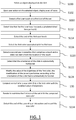
- FIGs. 3 to 11 show representations of a graphical tool for generating a color with the method as well as representations of examples of user interactions performed with the method.
- an object is selected on a graphical user interface (GUI); the object to be selected is displayed on the GUI.
- the display of the object is the result of a rendering.
- Rendering is the process of generating an image from a data of two-dimensional (2D) or three-dimensional (3D) model (or models in what collectively could be called a scene file) by means of a computer program.
- the object is any data that can be displayed. For instance, an image is an object, and an image display on a GUI may be selected by a user.
- a GUI is an interface that allows users to interact with a computer system.
- the GUI may show various types of graphic tools; for example, the GUI of a CAD system may comprise graphic tools for facilitating 3D orientation of the object, for triggering a simulation of an operation of an edited product or rendering various attributes of the displayed product.
- a cursor is in general used to interact with the GUI, e.g. the cursor of the haptic device 1090.
- the interactions can be performed directly on a touch sensitive display that displays the GUI, e.g. an appendage such as user finger(s) or a stylus are typically used for interacting with the GUI. It is to be understood that the present invention can be carried out on any kind of GUI accepting user inputs or user interactions.
- FIG. 14 shows an example a typical CAD-like interface, having standard menu bars 2110, 2120, as well as bottom and side toolbars 2140, 2150.
- Such menu- and toolbars contain a set of user-selectable icons, each icon being associated with one or more operations or functions, as known in the art.
- Some of these icons are associated with software tools, adapted for editing and/or working on the 3D modeled object 2000 displayed in the GUI 2100.
- the software tools may be grouped into workbenches. Each workbench comprises a subset of software tools. In particular, one of the workbenches is an edition workbench, suitable for editing geometrical features of the modeled product 2000.
- a designer may for example pre-select a part of the object 2000 and then initiate an operation (e.g. change the dimension, color, etc.) or edit geometrical constraints by selecting an appropriate icon.
- typical CAD operations are the modeling of the punching or the folding of the 3D modeled object displayed on the screen.
- the GUI may for example display data 2500 related to the displayed product 2000.
- the data 2500, displayed as a "feature tree", and their 3D representation 2000 pertain to a brake assembly including brake caliper and disc.
- the GUI may further show various types of graphic tools 2130, 2070, 2080 for example for facilitating 3D orientation of the object, for triggering a simulation of an operation of an edited product or render various attributes of the displayed product 2000.
- a cursor 2060 may be controlled by a haptic device to allow the user to interact with the graphic tools.
- the selection of the object is carried out as known in the art. For instance, the user performs a tap on the displayed object. Said otherwise, the user uses an appendage such as, but is not limited to, a finger or a stylet, for creating an interaction with the graphical representation of the object; the interaction is made through a touch sensitive display and interpreted by the system as a selection of the object displayed.
- an appendage such as, but is not limited to, a finger or a stylet
- a set of icons is displayed as a result of the selection of the object. For instance, a tap on the object at step S100 may be interpreted by the system as a command for selecting the object and for displaying the set of icons at the same time.
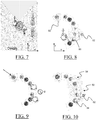
- FIG. 3 shows an example of a set of icons 30 that are displayed.
- the icons are 2D disks, being understood that icons are not limited to disk shapes.
- the icons may be also 3D icons, e.g. they are 3D objects displayed in a 3D scene.
- the icons may be also 2D icons represented with a perspective view in order to mimic a 3D representation.
- the icons 30 are placed on a 2D portion of a circular crown 32 that is also displayed on the GUI.
- the portion of a circular crown may be also a 3D object.
- the portion of a circular crown may be a 2D object represented with a perspective view in order to mimic a 3D representation.
- the 2D portion of the circular crown 32 may be contemplated as a layout on which the icons are laid on, being understood that the object 32 is not limited to this particular shape.
- the set of icons 30 and the portion 32 of the circular crown are displayed all at the same time after a user selection on the icon 20 of a toolbar 10 occurred. For instance, the user puts they finger on the icon 20.
- the toolbar 10 is displayed as a result of the selection of an object, for instance at step S100.
- the user selection of an object at step S100 can trigger the display of the toolbar 10, which in turn allows a user's selection of a color configuration mode, e.g. by performing a tap on the button 20.
- the icons of the set 30 may be substantially placed equidistant from a first location in the GUI. This first location is typically defined from a user interaction with the GUI, e.g. the user selection of the icon 20.
- the 2D representations of the objects 10, 20, 30 may be displayed in a 3D scene.
- the 2D objects 10, 20, 30 are over the view of the 3D scene, that is, they are displayed on a 2D plan wherein the scene and the objects are projected for display purpose.
- Each icon of the set is associated with a color.
- the term association means that there is a logical link between the icon and a color; or said otherwise, a user interaction on an icon of the set is likely to trigger an operation involving the color with which the icon is associated.
- the icon A of FIG. 3 is associated with the color grey; the icon D is associated with the color yellow.
- each icon of the set (the seven icons A to G) is associated with one color that is unique among the colors of the other icons; being understood that two or more icons might be associated with a same color.
- each icon is rendered with the color with which it is associated; for example, the icon A is rendered as a grey disk, the icon D as yellow disk.
- a first user interaction is detected on a first icon of the set.
- the user interaction can be made the same way as already discussed in reference to step S100.
- the user interaction may be a touch, that is, the user puts an appendage on the icon during a time period t. Said otherwise, a contact between the appendage and the touch screen is maintained during t.
- FIG. 4 illustrates an example of step S110: the user touches with their finger the icon E associated with the color green.
- the first user interaction can be carried out only on the graphical representation of the icon, that is, the location of the user interaction belong to the area defined by the icon.
- the first user interaction may be also performed on a zone of the GUI that extends the area of the icon: the user interactions performed on this zone are interpreted as having being made on the area defined by the icon.
- step S112 it is determined whether or not the duration of the first user interaction on the icon of the set is equal to or exceeds a predetermined time period t1.
- the user interaction is a touch and the first color that is associated with the touched icon is selected (S116).
- the selection S116 of the first color means that the first color can be used in subsequent steps that require a color, e.g. the parameters defining the selected first color are stored on memory for the purpose of a next use.
- the user interaction is a tap and the first color that is associated with the taped icon is applied on the object selected at step S100.
- Applying the color means that the rendering of the selected object is modified according to the color associated with the first icon. For instance, the selected object may be (partially or totally) colored with this color.
- the system performing the method may provide a signal to the user indicating that the time period t1 elapsed.
- the rendering of the icon may be modified, or the system may send a vibration of the user through the appendage, or a sound may be emitted by the system...
- the selection of the first color may be carried out afterthat the detection (S114) of the end of the first user touch is ended. This allows the user providing a confirmation to the system that they agree with the color to be selected.
- FIG. 5 shows an example of the representation of the set of icons after that the selection of the color associated with the icon E is effective.
- a blurred zone 50 surrounds the icon E for providing a visual indication of the selection of the color green associated with the icon E.
- two new visual indicators 52, 54 are also displayed together with the blurred zone 50.
- the representations are displayed in the close neighborhood of the icon E; they are represented on the blurred zone. The purpose of these two representations is to indicate to the user the new user interactions they can perform.
- a second user interaction is detected.
- the second user interaction comprises at least a slide.
- the term slide means a displacement of a user interaction from a first location on the touch sensitive display to a second one. For instance, the user puts one of their finger on the touch sensitive display and displaces it on the touch sensitive display -the finger is continuously in contact with the touch sensitive display and the system does not detect an end of the second user interaction between the first and second location on the GUI-.
- the second user interaction comprises a touch and a slide: the slide starts from the location on the touch sensitive display of the touch and the duration of the second user interaction is equal to or exceeds a predetermined duration.
- the second user interaction may be performed with the same appendage as the first one, or with a different one.
- the user can perform the second user interaction with the same finger used for selecting a color. Any combination of appendages may be contemplated.
- an orientation of the slide of the second user interaction on the GUI is detected.
- the orientation of the slide of the second user interaction is determined by the relative position of the first location of the slide on the GUI with the second location of the slide on the GUI.
- the detection of the orientation of the slide may further comprise the detection of the direction of the slide, as explained below.
- the second user interaction may be in the continuity of the first one; the second user interaction starts without the end of the first one is detected.
- the selection of step S116 is immediately carried out after the step S112 (that is, without the detection of step S114 ). For instance, the user puts a finger on the first icon at a first location in order to select a color (this is, the first user interaction is a touch), and when the color is selected, the user slides their finger from the first location (which is the location of the touch) to a second one; the slide is therefore the second user interaction.
- a value of a parameter of the first color associated with the first icon is modified.
- the parameter of a color can comprise, but is not limited to, any color appearance parameters such opacity, hue, lightness, brightness, chroma, colorfulness, saturation.
- the value of a parameter is modified, and the modification is performed according to the slide of the second user interaction.
- a given orientation of the slide allows selecting a color parameter and modifying a value of this particular parameter. For instance, a slide with a substantially horizontal orientation will trigger the selection of the parameter brightness of the selected color (the first color at step S122). As another example, a slide with a substantially vertical orientation will select the parameter opacity of the selected color. Further orientations of slide may be contemplated and one understands that any parameter may be associated with any slide orientation.
- the orientation of the slide of a user interaction is determined with reference to a frame of reference (x, y), e.g. the frame of reference of the GUI, the frame of reference of a portable device (smartphone, tablet) that implements the invention.
- the determination of the orientation of the slide may further comprise the detection of the direction of the slide.
- a vertically oriented slide can be performed from high to low and has therefore a direction referred to as DOWN; inversely, the vertically oriented slide can be performed from low to high and has therefore a direction referred to as UP.
- a horizontally oriented slide can have a left to the right direction and has therefore a direction referred to as RIGHT; inversely, the horizontally oriented slide can be performed from the right to the left and has therefore a direction referred to as LEFT. Therefore, the vertical orientation can be directed UP or DOWN, and the horizontal orientation can be directed RIGHT or LEFT.
- the distance of the slide allows modifying the value of the parameter.
- the value belongs to a range of values.
- Each value of the range can be associated with the parameter, being understood that one value at a time is associated with the parameter.
- the range of values may form a set of continuous values, as opposed to discrete values.
- the term value is synonym of data.
- the range of values can be finite or infinite.
- the modification of the value of the parameter is performed as known in the art.
- the increase or the decrease of the parameter value can be proportional to the distance of the displacement of the second user interaction from a first location to a second location.
- the distance may be a Euclidian distance, a number of pixels...
- the increase or the decrease of the parameter value may depend on the direction of the slide. For instance, an UP slide (a slide with a vertical orientation and a low to the high direction) may increase the value of the opacity, while the DOWN slide (a slide with a vertical orientation and a high to the low direction) may decrease it. As another example, the LEFT slide (a slide with a horizontal orientation and a right to the left direction) may decrease the value of the brightness of the first color, while the RIGHT slide (a slide with a horizontal orientation and a left to the right direction) may increase it.
- the parameter value can be modified.
- the new parameter value is set when the second user interaction is no more detected, e.g. the contact between the touch sensitive display and the appendage is no more detected.
- FIG. 6 shows an example of a second user interaction that is performed after the selection of the color of the icon E that is illustrated on FIG. 5 .
- the second user interaction starts with a contact performed on the icon E, for instance, the user uses one of their finger.
- the contact may be a touch, that is, the duration of the contact is equal to or exceeds a predetermined time period. The location of this touch is thus the first location from which the slide starts.
- the user horizontally slides their finger to the right for increasing the brightness of the color formerly selected (a RIGHT slide), or on the contrary they can move their finger to the left in order to decrease the brightness (a LEFT slide).
- the movement of slide is substantially parallel to the axis x: the slide is substantially horizontal. Substantially means that the angle between the axis x and the orientation of the slide does not exceed a predetermined angle, e.g. this angle is comprised between -45 and +45 degrees.
- FIG. 7 shows another example of second user interaction that is also performed after the selection of the color of the icon E.
- the second user interaction starts from a touch performed on the icon E that is illustrated on FIG. 5 .
- the user can vertically slide their finger up for increasing the opacity of the color associated with the icon E; an UP slide is done.
- the user can vertically move down their finger in order to decrease the opacity; a DOWN slide is done.
- the movement of slide is substantially parallel to the axis y: the slide is substantially vertical. Substantially means that the angle between the axis y and the direction of the slide does not exceed a predetermined angle, e.g. this angle is comprised between -45 and +45 degrees.
- FIG. 8 shows another illustration of the example of FIG. 7 .
- the user moves up their finger for increasing the opacity of the color associated with the icon E.
- the visual indicator 52 is now displayed for indicating the user that the opacity is currently modified.
- the first location 80 of the second user interaction is not performed on the icon E or on the zone of the icon E.
- the system knows that the next user interaction will concern the selected color, unless another user interaction is performed on another icon, as it will be discussed in reference to FIG. 2 . Therefore, the second user interaction can be executed outside the zone of the icon, but it will concern the color associated with the icon; this allows performing a second user interaction after the detection of the end of the first user interaction.
- a new color is computed in real-time from the first color on which the modified parameter value is applied: the former parameter value is thus replaced by the new parameter value.
- Computing in real-time means that the new color is computed as soon as a new value of the parameter is obtained upon the second user interaction.
- the term real-time does not refer to a guaranty of providing a response within available parameter value of this color, but rather to the ability to display a computed result when information required for computing the result is available to the system.
- the first icon may be re-rendered with the computed new color (S132); the re-rendering is preferably performed in real-time, that is, each time a new color is computed.
- the user benefits therefore of a visual feedback of the current parameter value.
- the display of the new color may be performed with another icon of the set.
- This icon is preferably an icon dedicated to the record of a new color obtained with the present method: this icon is associated with a user-defined color.
- the icon H on FIG. 8 displays the new color (step S132), and the original rendering of the first icon is not modified (the icon E is still rendered in green).
- the last computed new color is recorded, for instance upon user action by clicking on the add button 82 of FIG. 8 .
- the recorded new color can be applied on an object, e.g. on the selected object of step S100, or on another object. Applying the new color means that at least a part of the object is re-rendered with this new color.
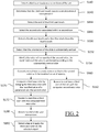
- FIG. 2 it is discussed a second example of the invention in which the generated color is obtained from the merge of two colors.
- One of these two colors can be obtained by performing the method discussed in reference of FIG. 1 .
- a third user interaction is detected on a second icon of the set, e.g. the third user interaction is a touch.
- the step S140 is similar to the step S110.
- the second icon may be the same or not as the first one of step S110.
- the third user interaction is performed while the second user interaction is still detected. The system thus knows that a merge of color is going to be carried out.
- the user can select a color by performing a touch on one of the icons of the set as explained in reference to steps S110 to S116.
- the user can also recall the color recorded at step S134, e.g. they perform a touch on the icon 80 that is associated with a user-defined color. In both cases, a user interaction is still detected in addition to the third one.
- the step S140 is performed before detecting the end of the first user interaction (S114).
- the system knows that a new color will be computed by merging the first color and a second color (modified or not).
- step S142 one determines that the third user interaction exceeds a predetermined time period t2.
- the step S142 is similar to the step S112.
- the time period t2 may be equal, smaller or larger than t1.
- t1 and t2 have a same value so that there is no difference for the user between the first and third user interactions.
- FIG. 9 illustrates an example of step S142: the user touches with their finger the icon C associated with the color orange while the user touch on the icon E is maintained.
- step S144 the end of the third user interaction is detected.
- the step S144 is similar to the step S114.
- step S146 a second color that is associated with the second icon is selected. This is done the same way as discussed for step S116.
- a new color may be computed by merging the first new color computed at step S130 with the second color that is associated with the selected second icon of step S146.
- the computed new color is the merge of a modified color and an unmodified color that are selected upon user interactions.
- the new color may be computed by merging the first color that is associated with the selected first icon at step S116 with the second color that is associated with the selected second icon of step S146.
- the computed new color is the merge of two unmodified colors selected upon user interactions. This computed new color can be displayed as discussed in reference to steps S130-S134.
- FIG. 10 shows the situation in which two colors have been selected. Both icons E and C are surrounded by blurred zones for providing a visual indication of the selection of the color green and color orange associated with the icons E and C. Still in reference to FIG. 10 , two new indicators 52, 54 are also displayed together with the blurred zone 50. In this example, the indicators are displayed in the close neighborhood of the icon E and they are represented over the blurred zone 50. In another example, the two new representations 52, 54 might be represented over the blurred zone 56 of the last selected icon C.
- the user may release the first or the second user interaction, depending on whether the user has or not modified at least one parameter value of the selected first color.
- the system knows that a new color will be computed by merging the first color (modified or not) and the second color (modified or not).
- the second color can be modified only with the fourth user interaction of the example of the steps S150, S152, S154, S160.
- These fourth steps are similar to the steps S120, S122, S124, S130, except that the slide in this example is substantially vertical and that the parameter value tuned by the user is the opacity of the second color.
- the selected second color can be modified by using both the first and the fourth user interactions or the second and fourth user interactions.
- the user can simultaneously modify values of two parameters of the selected second color, e.g. by sliding their two fingers.
- step S162 a second icon of the set (the one selected at step S140-S146) is re-rendered in real-time with the second new color computed at step S160.
- the re-rendering of step S162 is similar to the one described in reference to step S132.
- the step S162 is not carried out as the user does not need to see the modification of the color of the second icon, but rather the third new color obtained as a result of steps S170 to S180.
- a third new color is computed by merging the first new color computed at step S130 with the second new color computed at step S160.
- the merge of two colors is performed as known in the art: merging two colors is also referred to as color mixing.
- Color merging (or color mixing) can be done, for example, by performing an additive mixing of colors or a subtractive mixing of colors.
- the third new color is preferably rendered on an icon dedicated to the record of a new color obtained with the present method. Hence, this icon is associated with a user-defined color.
- the icon H is associated with the third new color and is rendered in real-time with this third new color (S172).
- step S180 the end of the user interactions is detected; this triggers the recording of the third new color.
- the recording can also be carried out upon user action by clicking on the add button 82.
- step S182 a fifth user interaction is detected, and the third new color is applied on the select object.
- the fifth user action may be performed on the icon H that is associated with the third new color.
- the selected colors are those associated with the set of icons. It is to be understood that a color obtained and recorded can be used for generating a new color. The recorded color is associated with an icon used for displaying user-made colors, for instance with the icon H discussed in reference with FIG. 8 and 10 .
- FIGs. 11a to 11d show examples of color wheels, as known in the art.
- the color wheels depict relationships between colors, and can be used for computing a merge of primary, secondary, tertiary colors. These primary, secondary, tertiary colors may be associated with the icons of the set.
- FIG. 12 is a flowchart that shows the different examples and alternatives discussed in relation with FIGs. 1 and 2 . As it is apparent on FIG. 12 , many combinations of user interactions can be performed. FIG. 15 shows examples of different combinations of user interactions (Ul).
- the examples of the invention have been discussed with user interactions performed on a touch-sensitive display. It is to be understood that the present invention can be performed with user-interactions that are not necessarily done with a contact between an appendage and a touch sensitive display. For instance, a user interaction can be detected when the appendage is close to the display, or even simulated in a context of virtual environment.
Priority Applications (5)
| Application Number | Priority Date | Filing Date | Title |
|---|---|---|---|
| EP16305798.7A EP3264251B1 (en) | 2016-06-29 | 2016-06-29 | Generation of a color of an object displayed on a gui |
| JP2017125154A JP6978863B2 (ja) | 2016-06-29 | 2017-06-27 | Gui上に表示されたオブジェクトの色の生成 |
| US15/637,100 US11334233B2 (en) | 2016-06-29 | 2017-06-29 | Generation of a color of an object displayed on a GUI |
| CN201710516261.2A CN107544797B (zh) | 2016-06-29 | 2017-06-29 | 用于生成在图形用户接口上显示的对象色彩的方法和装置 |
| US17/743,635 US11733851B2 (en) | 2016-06-29 | 2022-05-13 | Generation of a color of an object displayed on a GUI |
Applications Claiming Priority (1)
| Application Number | Priority Date | Filing Date | Title |
|---|---|---|---|
| EP16305798.7A EP3264251B1 (en) | 2016-06-29 | 2016-06-29 | Generation of a color of an object displayed on a gui |
Publications (2)
| Publication Number | Publication Date |
|---|---|
| EP3264251A1 EP3264251A1 (en) | 2018-01-03 |
| EP3264251B1 true EP3264251B1 (en) | 2019-09-04 |
Family
ID=56551352
Family Applications (1)
| Application Number | Title | Priority Date | Filing Date |
|---|---|---|---|
| EP16305798.7A Active EP3264251B1 (en) | 2016-06-29 | 2016-06-29 | Generation of a color of an object displayed on a gui |
Country Status (4)
| Country | Link |
|---|---|
| US (2) | US11334233B2 (zh) |
| EP (1) | EP3264251B1 (zh) |
| JP (1) | JP6978863B2 (zh) |
| CN (1) | CN107544797B (zh) |
Families Citing this family (19)
| Publication number | Priority date | Publication date | Assignee | Title |
|---|---|---|---|---|
| TWI439960B (zh) | 2010-04-07 | 2014-06-01 | Apple Inc | 虛擬使用者編輯環境 |
| KR20210013323A (ko) | 2016-09-23 | 2021-02-03 | 애플 인크. | 아바타 생성 및 편집 |
| DK179978B1 (en) | 2016-09-23 | 2019-11-27 | Apple Inc. | IMAGE DATA FOR ENHANCED USER INTERACTIONS |
| KR20180051288A (ko) * | 2016-11-08 | 2018-05-16 | 삼성전자주식회사 | 디스플레이 장치 및 그 제어 방법 |
| JP1590263S (zh) | 2016-12-28 | 2017-11-06 | ||
| JP1589999S (zh) * | 2016-12-28 | 2017-11-06 | ||
| KR102439054B1 (ko) | 2017-05-16 | 2022-09-02 | 애플 인크. | 이모지 레코딩 및 전송 |
| DK179948B1 (en) | 2017-05-16 | 2019-10-22 | Apple Inc. | Recording and sending Emoji |
| DK201870378A1 (en) | 2018-05-07 | 2020-01-13 | Apple Inc. | DISPLAYING USER INTERFACES ASSOCIATED WITH PHYSICAL ACTIVITIES |
| US11722764B2 (en) | 2018-05-07 | 2023-08-08 | Apple Inc. | Creative camera |
| US10375313B1 (en) | 2018-05-07 | 2019-08-06 | Apple Inc. | Creative camera |
| DK180212B1 (en) | 2018-05-07 | 2020-08-19 | Apple Inc | USER INTERFACE FOR CREATING AVATAR |
| US11107261B2 (en) | 2019-01-18 | 2021-08-31 | Apple Inc. | Virtual avatar animation based on facial feature movement |
| DK201970531A1 (en) | 2019-05-06 | 2021-07-09 | Apple Inc | Avatar integration with multiple applications |
| DK202070625A1 (en) | 2020-05-11 | 2022-01-04 | Apple Inc | User interfaces related to time |
| US11921998B2 (en) | 2020-05-11 | 2024-03-05 | Apple Inc. | Editing features of an avatar |
| KR20220104921A (ko) * | 2021-01-19 | 2022-07-26 | 라인플러스 주식회사 | 디스플레이 모드 기반 그래픽 객체 제공 방법 및 시스템 |
| US11714536B2 (en) | 2021-05-21 | 2023-08-01 | Apple Inc. | Avatar sticker editor user interfaces |
| US11776190B2 (en) | 2021-06-04 | 2023-10-03 | Apple Inc. | Techniques for managing an avatar on a lock screen |
Citations (1)
| Publication number | Priority date | Publication date | Assignee | Title |
|---|---|---|---|---|
| US20130326381A1 (en) * | 2012-05-29 | 2013-12-05 | Microsoft Corporation | Digital art program interaction and mechanisms |
Family Cites Families (18)
| Publication number | Priority date | Publication date | Assignee | Title |
|---|---|---|---|---|
| US7071950B2 (en) * | 2000-09-01 | 2006-07-04 | Ricoh Co., Ltd. | Super imposed image display color selection system and method |
| US7898397B2 (en) * | 2007-06-12 | 2011-03-01 | Apple Inc. | Selectively adjustable icons for assisting users of an electronic device |
| US20090231356A1 (en) * | 2008-03-17 | 2009-09-17 | Photometria, Inc. | Graphical user interface for selection of options from option groups and methods relating to same |
| US20110074807A1 (en) * | 2009-09-30 | 2011-03-31 | Hitachi, Ltd. | Method of color customization of content screen |
| JP4981946B2 (ja) | 2010-03-29 | 2012-07-25 | 株式会社エヌ・ティ・ティ・ドコモ | 携帯端末及び携帯端末における文字色変更方法 |
| US20110292069A1 (en) * | 2010-05-28 | 2011-12-01 | Witt David Joseph | RGB Color Mixer |
| CN102622214B (zh) * | 2011-01-27 | 2015-09-30 | 腾讯科技(深圳)有限公司 | 一种实现多种显示模式通用图标的方法与装置 |
| US8762866B2 (en) * | 2011-04-08 | 2014-06-24 | Adobe Systems Incorporated | Remote paint mixing controller |
| US9424799B2 (en) * | 2011-10-28 | 2016-08-23 | Apple Inc. | On-screen image adjustments |
| CN104221359B (zh) * | 2012-03-06 | 2018-01-12 | 苹果公司 | 用于色彩片段的色彩调节器 |
| US9131192B2 (en) * | 2012-03-06 | 2015-09-08 | Apple Inc. | Unified slider control for modifying multiple image properties |
| US9563972B2 (en) * | 2012-10-22 | 2017-02-07 | FifthyThree, Inc. | Methods and apparatus for providing color palette management within a graphical user interface |
| JP5751283B2 (ja) * | 2013-06-04 | 2015-07-22 | コニカミノルタ株式会社 | 色調整システム、色調整方法、および色調整プログラム |
| CN103870155B (zh) * | 2014-02-21 | 2017-08-25 | 联想(北京)有限公司 | 信息处理的方法及电子设备 |
| US10558334B2 (en) * | 2014-03-31 | 2020-02-11 | Htc Corporation | Electronic device and method for messaging |
| CN104050004B (zh) * | 2014-06-30 | 2018-01-09 | 宇龙计算机通信科技(深圳)有限公司 | 界面图标色彩设置方法、装置及终端 |
| US10489051B2 (en) * | 2014-11-28 | 2019-11-26 | Samsung Electronics Co., Ltd. | Handwriting input apparatus and control method thereof |
| KR20170053435A (ko) * | 2015-11-06 | 2017-05-16 | 삼성전자주식회사 | 전자 장치 및 전자 장치에서의 이미지 편집 방법 |
-
2016
- 2016-06-29 EP EP16305798.7A patent/EP3264251B1/en active Active
-
2017
- 2017-06-27 JP JP2017125154A patent/JP6978863B2/ja active Active
- 2017-06-29 CN CN201710516261.2A patent/CN107544797B/zh active Active
- 2017-06-29 US US15/637,100 patent/US11334233B2/en active Active
-
2022
- 2022-05-13 US US17/743,635 patent/US11733851B2/en active Active
Patent Citations (1)
| Publication number | Priority date | Publication date | Assignee | Title |
|---|---|---|---|---|
| US20130326381A1 (en) * | 2012-05-29 | 2013-12-05 | Microsoft Corporation | Digital art program interaction and mechanisms |
Also Published As
| Publication number | Publication date |
|---|---|
| CN107544797B (zh) | 2022-11-08 |
| US20220269402A1 (en) | 2022-08-25 |
| EP3264251A1 (en) | 2018-01-03 |
| JP2018041441A (ja) | 2018-03-15 |
| US11334233B2 (en) | 2022-05-17 |
| JP6978863B2 (ja) | 2021-12-08 |
| CN107544797A (zh) | 2018-01-05 |
| US11733851B2 (en) | 2023-08-22 |
| US20180004404A1 (en) | 2018-01-04 |
Similar Documents
| Publication | Publication Date | Title |
|---|---|---|
| US11733851B2 (en) | Generation of a color of an object displayed on a GUI | |
| US11256832B2 (en) | Replica selection | |
| US10002465B2 (en) | Creation of bounding boxes on a 3D modeled assembly | |
| US10706186B2 (en) | B-rep design with face trajectories | |
| US11163915B2 (en) | Three-dimensional modeled object | |
| US10372290B2 (en) | Comparing 3D modeled objects | |
| US11087051B2 (en) | Designing a multi-physics system | |
| EP3040946B1 (en) | Viewpoint selection in the rendering of a set of objects | |
| EP3506133A1 (en) | Method of assembling parts of a product | |
| KR102055952B1 (ko) | 오브젝트들의 원형 스태거드 패턴의 설계 | |
| US20200211296A1 (en) | Flexible modeling using a weak type definition | |
| US20230195296A1 (en) | Setting typed parameter | |
| US11941773B2 (en) | Method for designing a three-dimensional mesh in a 3D scene |
Legal Events
| Date | Code | Title | Description |
|---|---|---|---|
| PUAI | Public reference made under article 153(3) epc to a published international application that has entered the european phase |
Free format text: ORIGINAL CODE: 0009012 |
|
| STAA | Information on the status of an ep patent application or granted ep patent |
Free format text: STATUS: THE APPLICATION HAS BEEN PUBLISHED |
|
| AK | Designated contracting states |
Kind code of ref document: A1 Designated state(s): AL AT BE BG CH CY CZ DE DK EE ES FI FR GB GR HR HU IE IS IT LI LT LU LV MC MK MT NL NO PL PT RO RS SE SI SK SM TR |
|
| AX | Request for extension of the european patent |
Extension state: BA ME |
|
| STAA | Information on the status of an ep patent application or granted ep patent |
Free format text: STATUS: REQUEST FOR EXAMINATION WAS MADE |
|
| 17P | Request for examination filed |
Effective date: 20180703 |
|
| RBV | Designated contracting states (corrected) |
Designated state(s): AL AT BE BG CH CY CZ DE DK EE ES FI FR GB GR HR HU IE IS IT LI LT LU LV MC MK MT NL NO PL PT RO RS SE SI SK SM TR |
|
| GRAP | Despatch of communication of intention to grant a patent |
Free format text: ORIGINAL CODE: EPIDOSNIGR1 |
|
| STAA | Information on the status of an ep patent application or granted ep patent |
Free format text: STATUS: GRANT OF PATENT IS INTENDED |
|
| INTG | Intention to grant announced |
Effective date: 20190214 |
|
| GRAJ | Information related to disapproval of communication of intention to grant by the applicant or resumption of examination proceedings by the epo deleted |
Free format text: ORIGINAL CODE: EPIDOSDIGR1 |
|
| GRAL | Information related to payment of fee for publishing/printing deleted |
Free format text: ORIGINAL CODE: EPIDOSDIGR3 |
|
| GRAS | Grant fee paid |
Free format text: ORIGINAL CODE: EPIDOSNIGR3 |
|
| STAA | Information on the status of an ep patent application or granted ep patent |
Free format text: STATUS: REQUEST FOR EXAMINATION WAS MADE |
|
| GRAR | Information related to intention to grant a patent recorded |
Free format text: ORIGINAL CODE: EPIDOSNIGR71 |
|
| STAA | Information on the status of an ep patent application or granted ep patent |
Free format text: STATUS: GRANT OF PATENT IS INTENDED |
|
| INTC | Intention to grant announced (deleted) | ||
| GRAA | (expected) grant |
Free format text: ORIGINAL CODE: 0009210 |
|
| STAA | Information on the status of an ep patent application or granted ep patent |
Free format text: STATUS: THE PATENT HAS BEEN GRANTED |
|
| AK | Designated contracting states |
Kind code of ref document: B1 Designated state(s): AL AT BE BG CH CY CZ DE DK EE ES FI FR GB GR HR HU IE IS IT LI LT LU LV MC MK MT NL NO PL PT RO RS SE SI SK SM TR |
|
| INTG | Intention to grant announced |
Effective date: 20190726 |
|
| REG | Reference to a national code |
Ref country code: GB Ref legal event code: FG4D |
|
| REG | Reference to a national code |
Ref country code: CH Ref legal event code: EP |
|
| REG | Reference to a national code |
Ref country code: AT Ref legal event code: REF Ref document number: 1176315 Country of ref document: AT Kind code of ref document: T Effective date: 20190915 |
|
| REG | Reference to a national code |
Ref country code: DE Ref legal event code: R096 Ref document number: 602016019833 Country of ref document: DE |
|
| REG | Reference to a national code |
Ref country code: IE Ref legal event code: FG4D |
|
| REG | Reference to a national code |
Ref country code: SE Ref legal event code: TRGR |
|
| REG | Reference to a national code |
Ref country code: NL Ref legal event code: MP Effective date: 20190904 |
|
| REG | Reference to a national code |
Ref country code: LT Ref legal event code: MG4D |
|
| PG25 | Lapsed in a contracting state [announced via postgrant information from national office to epo] |
Ref country code: FI Free format text: LAPSE BECAUSE OF FAILURE TO SUBMIT A TRANSLATION OF THE DESCRIPTION OR TO PAY THE FEE WITHIN THE PRESCRIBED TIME-LIMIT Effective date: 20190904 Ref country code: HR Free format text: LAPSE BECAUSE OF FAILURE TO SUBMIT A TRANSLATION OF THE DESCRIPTION OR TO PAY THE FEE WITHIN THE PRESCRIBED TIME-LIMIT Effective date: 20190904 Ref country code: LT Free format text: LAPSE BECAUSE OF FAILURE TO SUBMIT A TRANSLATION OF THE DESCRIPTION OR TO PAY THE FEE WITHIN THE PRESCRIBED TIME-LIMIT Effective date: 20190904 Ref country code: NO Free format text: LAPSE BECAUSE OF FAILURE TO SUBMIT A TRANSLATION OF THE DESCRIPTION OR TO PAY THE FEE WITHIN THE PRESCRIBED TIME-LIMIT Effective date: 20191204 Ref country code: BG Free format text: LAPSE BECAUSE OF FAILURE TO SUBMIT A TRANSLATION OF THE DESCRIPTION OR TO PAY THE FEE WITHIN THE PRESCRIBED TIME-LIMIT Effective date: 20191204 |
|
| PG25 | Lapsed in a contracting state [announced via postgrant information from national office to epo] |
Ref country code: AL Free format text: LAPSE BECAUSE OF FAILURE TO SUBMIT A TRANSLATION OF THE DESCRIPTION OR TO PAY THE FEE WITHIN THE PRESCRIBED TIME-LIMIT Effective date: 20190904 Ref country code: ES Free format text: LAPSE BECAUSE OF FAILURE TO SUBMIT A TRANSLATION OF THE DESCRIPTION OR TO PAY THE FEE WITHIN THE PRESCRIBED TIME-LIMIT Effective date: 20190904 Ref country code: RS Free format text: LAPSE BECAUSE OF FAILURE TO SUBMIT A TRANSLATION OF THE DESCRIPTION OR TO PAY THE FEE WITHIN THE PRESCRIBED TIME-LIMIT Effective date: 20190904 Ref country code: LV Free format text: LAPSE BECAUSE OF FAILURE TO SUBMIT A TRANSLATION OF THE DESCRIPTION OR TO PAY THE FEE WITHIN THE PRESCRIBED TIME-LIMIT Effective date: 20190904 Ref country code: GR Free format text: LAPSE BECAUSE OF FAILURE TO SUBMIT A TRANSLATION OF THE DESCRIPTION OR TO PAY THE FEE WITHIN THE PRESCRIBED TIME-LIMIT Effective date: 20191205 |
|
| REG | Reference to a national code |
Ref country code: AT Ref legal event code: MK05 Ref document number: 1176315 Country of ref document: AT Kind code of ref document: T Effective date: 20190904 |
|
| PG25 | Lapsed in a contracting state [announced via postgrant information from national office to epo] |
Ref country code: RO Free format text: LAPSE BECAUSE OF FAILURE TO SUBMIT A TRANSLATION OF THE DESCRIPTION OR TO PAY THE FEE WITHIN THE PRESCRIBED TIME-LIMIT Effective date: 20190904 Ref country code: PT Free format text: LAPSE BECAUSE OF FAILURE TO SUBMIT A TRANSLATION OF THE DESCRIPTION OR TO PAY THE FEE WITHIN THE PRESCRIBED TIME-LIMIT Effective date: 20200106 Ref country code: PL Free format text: LAPSE BECAUSE OF FAILURE TO SUBMIT A TRANSLATION OF THE DESCRIPTION OR TO PAY THE FEE WITHIN THE PRESCRIBED TIME-LIMIT Effective date: 20190904 Ref country code: NL Free format text: LAPSE BECAUSE OF FAILURE TO SUBMIT A TRANSLATION OF THE DESCRIPTION OR TO PAY THE FEE WITHIN THE PRESCRIBED TIME-LIMIT Effective date: 20190904 Ref country code: AT Free format text: LAPSE BECAUSE OF FAILURE TO SUBMIT A TRANSLATION OF THE DESCRIPTION OR TO PAY THE FEE WITHIN THE PRESCRIBED TIME-LIMIT Effective date: 20190904 Ref country code: EE Free format text: LAPSE BECAUSE OF FAILURE TO SUBMIT A TRANSLATION OF THE DESCRIPTION OR TO PAY THE FEE WITHIN THE PRESCRIBED TIME-LIMIT Effective date: 20190904 |
|
| PG25 | Lapsed in a contracting state [announced via postgrant information from national office to epo] |
Ref country code: CZ Free format text: LAPSE BECAUSE OF FAILURE TO SUBMIT A TRANSLATION OF THE DESCRIPTION OR TO PAY THE FEE WITHIN THE PRESCRIBED TIME-LIMIT Effective date: 20190904 Ref country code: SK Free format text: LAPSE BECAUSE OF FAILURE TO SUBMIT A TRANSLATION OF THE DESCRIPTION OR TO PAY THE FEE WITHIN THE PRESCRIBED TIME-LIMIT Effective date: 20190904 Ref country code: SM Free format text: LAPSE BECAUSE OF FAILURE TO SUBMIT A TRANSLATION OF THE DESCRIPTION OR TO PAY THE FEE WITHIN THE PRESCRIBED TIME-LIMIT Effective date: 20190904 Ref country code: IS Free format text: LAPSE BECAUSE OF FAILURE TO SUBMIT A TRANSLATION OF THE DESCRIPTION OR TO PAY THE FEE WITHIN THE PRESCRIBED TIME-LIMIT Effective date: 20200224 |
|
| REG | Reference to a national code |
Ref country code: DE Ref legal event code: R097 Ref document number: 602016019833 Country of ref document: DE |
|
| PLBE | No opposition filed within time limit |
Free format text: ORIGINAL CODE: 0009261 |
|
| STAA | Information on the status of an ep patent application or granted ep patent |
Free format text: STATUS: NO OPPOSITION FILED WITHIN TIME LIMIT |
|
| PG2D | Information on lapse in contracting state deleted |
Ref country code: IS |
|
| PG25 | Lapsed in a contracting state [announced via postgrant information from national office to epo] |
Ref country code: DK Free format text: LAPSE BECAUSE OF FAILURE TO SUBMIT A TRANSLATION OF THE DESCRIPTION OR TO PAY THE FEE WITHIN THE PRESCRIBED TIME-LIMIT Effective date: 20190904 Ref country code: IS Free format text: LAPSE BECAUSE OF FAILURE TO SUBMIT A TRANSLATION OF THE DESCRIPTION OR TO PAY THE FEE WITHIN THE PRESCRIBED TIME-LIMIT Effective date: 20200105 |
|
| 26N | No opposition filed |
Effective date: 20200605 |
|
| PG25 | Lapsed in a contracting state [announced via postgrant information from national office to epo] |
Ref country code: SI Free format text: LAPSE BECAUSE OF FAILURE TO SUBMIT A TRANSLATION OF THE DESCRIPTION OR TO PAY THE FEE WITHIN THE PRESCRIBED TIME-LIMIT Effective date: 20190904 |
|
| PG25 | Lapsed in a contracting state [announced via postgrant information from national office to epo] |
Ref country code: MC Free format text: LAPSE BECAUSE OF FAILURE TO SUBMIT A TRANSLATION OF THE DESCRIPTION OR TO PAY THE FEE WITHIN THE PRESCRIBED TIME-LIMIT Effective date: 20190904 |
|
| REG | Reference to a national code |
Ref country code: CH Ref legal event code: PL |
|
| PG25 | Lapsed in a contracting state [announced via postgrant information from national office to epo] |
Ref country code: LU Free format text: LAPSE BECAUSE OF NON-PAYMENT OF DUE FEES Effective date: 20200629 |
|
| REG | Reference to a national code |
Ref country code: BE Ref legal event code: MM Effective date: 20200630 |
|
| PG25 | Lapsed in a contracting state [announced via postgrant information from national office to epo] |
Ref country code: IE Free format text: LAPSE BECAUSE OF NON-PAYMENT OF DUE FEES Effective date: 20200629 Ref country code: CH Free format text: LAPSE BECAUSE OF NON-PAYMENT OF DUE FEES Effective date: 20200630 Ref country code: LI Free format text: LAPSE BECAUSE OF NON-PAYMENT OF DUE FEES Effective date: 20200630 |
|
| PG25 | Lapsed in a contracting state [announced via postgrant information from national office to epo] |
Ref country code: BE Free format text: LAPSE BECAUSE OF NON-PAYMENT OF DUE FEES Effective date: 20200630 |
|
| PG25 | Lapsed in a contracting state [announced via postgrant information from national office to epo] |
Ref country code: TR Free format text: LAPSE BECAUSE OF FAILURE TO SUBMIT A TRANSLATION OF THE DESCRIPTION OR TO PAY THE FEE WITHIN THE PRESCRIBED TIME-LIMIT Effective date: 20190904 Ref country code: MT Free format text: LAPSE BECAUSE OF FAILURE TO SUBMIT A TRANSLATION OF THE DESCRIPTION OR TO PAY THE FEE WITHIN THE PRESCRIBED TIME-LIMIT Effective date: 20190904 Ref country code: CY Free format text: LAPSE BECAUSE OF FAILURE TO SUBMIT A TRANSLATION OF THE DESCRIPTION OR TO PAY THE FEE WITHIN THE PRESCRIBED TIME-LIMIT Effective date: 20190904 |
|
| PG25 | Lapsed in a contracting state [announced via postgrant information from national office to epo] |
Ref country code: MK Free format text: LAPSE BECAUSE OF FAILURE TO SUBMIT A TRANSLATION OF THE DESCRIPTION OR TO PAY THE FEE WITHIN THE PRESCRIBED TIME-LIMIT Effective date: 20190904 |
|
| P01 | Opt-out of the competence of the unified patent court (upc) registered |
Effective date: 20230527 |
|
| PGFP | Annual fee paid to national office [announced via postgrant information from national office to epo] |
Ref country code: FR Payment date: 20230628 Year of fee payment: 8 Ref country code: DE Payment date: 20230620 Year of fee payment: 8 |
|
| PGFP | Annual fee paid to national office [announced via postgrant information from national office to epo] |
Ref country code: SE Payment date: 20230620 Year of fee payment: 8 |
|
| PGFP | Annual fee paid to national office [announced via postgrant information from national office to epo] |
Ref country code: IT Payment date: 20230623 Year of fee payment: 8 Ref country code: GB Payment date: 20230622 Year of fee payment: 8 |