EP3264199A1 - Timepiece comprising a switching device of a clockwork mechanism - Google Patents
Timepiece comprising a switching device of a clockwork mechanism Download PDFInfo
- Publication number
- EP3264199A1 EP3264199A1 EP16177617.4A EP16177617A EP3264199A1 EP 3264199 A1 EP3264199 A1 EP 3264199A1 EP 16177617 A EP16177617 A EP 16177617A EP 3264199 A1 EP3264199 A1 EP 3264199A1
- Authority
- EP
- European Patent Office
- Prior art keywords
- magnetic
- control member
- rotation
- axis
- rotary control
- Prior art date
- Legal status (The legal status is an assumption and is not a legal conclusion. Google has not performed a legal analysis and makes no representation as to the accuracy of the status listed.)
- Withdrawn
Links
Images


Classifications
-
- G—PHYSICS
- G04—HOROLOGY
- G04F—TIME-INTERVAL MEASURING
- G04F7/00—Apparatus for measuring unknown time intervals by non-electric means
- G04F7/04—Apparatus for measuring unknown time intervals by non-electric means using a mechanical oscillator
- G04F7/08—Watches or clocks with stop devices, e.g. chronograph
- G04F7/0842—Watches or clocks with stop devices, e.g. chronograph with start-stop control mechanisms
-
- G—PHYSICS
- G04—HOROLOGY
- G04B—MECHANICALLY-DRIVEN CLOCKS OR WATCHES; MECHANICAL PARTS OF CLOCKS OR WATCHES IN GENERAL; TIME PIECES USING THE POSITION OF THE SUN, MOON OR STARS
- G04B11/00—Click devices; Stop clicks; Clutches
- G04B11/001—Clutch mechanism between two rotating members with transfer of movement in both directions, possibly with limitation on the transfer of power
- G04B11/005—Clutch mechanism between two rotating members with transfer of movement in both directions, possibly with limitation on the transfer of power with magnetic elements
-
- G—PHYSICS
- G04—HOROLOGY
- G04F—TIME-INTERVAL MEASURING
- G04F7/00—Apparatus for measuring unknown time intervals by non-electric means
- G04F7/04—Apparatus for measuring unknown time intervals by non-electric means using a mechanical oscillator
- G04F7/08—Watches or clocks with stop devices, e.g. chronograph
- G04F7/0804—Watches or clocks with stop devices, e.g. chronograph with reset mechanisms
- G04F7/0814—Watches or clocks with stop devices, e.g. chronograph with reset mechanisms with double hammer, i.e. one hammer acts on two counters
-
- G—PHYSICS
- G04—HOROLOGY
- G04F—TIME-INTERVAL MEASURING
- G04F7/00—Apparatus for measuring unknown time intervals by non-electric means
- G04F7/04—Apparatus for measuring unknown time intervals by non-electric means using a mechanical oscillator
- G04F7/08—Watches or clocks with stop devices, e.g. chronograph
- G04F7/0842—Watches or clocks with stop devices, e.g. chronograph with start-stop control mechanisms
- G04F7/0847—Watches or clocks with stop devices, e.g. chronograph with start-stop control mechanisms with column wheel
Definitions
- the present invention relates to a switching device of a clock mechanism between two functional states.
- the present invention relates to a timepiece comprising, on the one hand, a watch mechanism that can switch between a first state and a second determined state and, on the other hand, a switching device arranged to switch on command the clock mechanism between its first and second states.
- This switching device comprises a movable switching member and a rotary control member which is arranged to be driven step-by-step in a given direction of rotation, so as to successively occupy a plurality of angular positions around an axis of rotation. rotation of this control member.
- the switching device is arranged so that a step-by-step rotation of the rotary control member causes reciprocating movement of the movable switching member, substantially in a plane perpendicular to said axis of rotation, so that at least a part of this movable switching member moves between two radial positions for which the clock mechanism is respectively in its first state and its second state.
- the document EP 2,602,675 describes a watch movement that includes a column wheel chronograph mechanism, the latter forming a rotary control member of the chronograph mechanism which has two functional states, namely "on" and "off".
- the watch movement described in this prior document therefore comprises a column wheel and a clutch rocker arranged to cooperate with the column wheel in order to start or stop the chronograph mechanism.
- the column wheel is driven in order to rotate in steps in one direction of rotation while the clutch rocker is reciprocated between two determined radial positions for which the chronograph mechanism is respectively in both states. aforementioned functionalities.
- the known switching devices generally comprise a rotary control member consisting of a cam or a column wheel, and a movable switching member. in the form of a cam follower of one type or another and more specifically constituted by a rocker or a lever.
- a disadvantage of such switching devices is that they all in principle require the use of prestressed springs to return and maintain the movable switching member against the cam or the column wheel.
- Watch springs are bulky and delicate. They are subject to aging which gradually makes them lose effectiveness. This aging is also considerably accelerated by the shocks that may be experienced by the timepiece. On the other hand, by always returning the mobile switching member in abutment against the cam, the springs accelerate the wear of these two components.
- watch springs with their small dimensions are quite sensitive to tolerances, which is an additional problem.
- An object of the present invention is to overcome the disadvantages of the prior art which have just been described.
- the invention achieves this goal by providing a timepiece according to the appended claim 1.
- the switching device comprises a mobile switching member and a rotary control member respectively carrying a first magnetic structure and a second magnetic structure arranged so as to have a magnetic interaction between them which makes it possible to switch to command the clock mechanism between a first state and a second state.
- One of the first and second magnetic structures comprises at least one first magnetic pole and the other of these two magnetic structures comprises at least one second magnetic pole and a third magnetic pole with opposite polarities and capable of interacting successively with the first magnetic pole. magnetic pole.
- the first and second magnetic structures are arranged so that, in a first angular position of the rotary control member, a first magnetic force, generated by a magnetic interaction between the first and second magnetic poles, acts on the switching member.
- a second magnetic force generated by a magnetic interaction between the first and third magnetic poles and thus in the opposite direction to the first magnetic force, acts on the switching member so as to recall the latter in the other of its two stable radial positions.
- the two stable radial positions relate more specifically to an end portion of the organ. of commutation.
- a sliding switch member it is the whole of this member which undergoes a translation movement in a plane substantially perpendicular to said axis of rotation between two stable radial positions of its center of mass.
- Such a magnetic system has the advantage of being a non-contact system capable of alternately exerting two forces with opposite directions on the switching member.
- the appended figures 1 to 5 illustrate a first embodiment of the invention which is constituted by a timepiece comprising a striking mechanism that can switch between a first state where the ringing is activated and a second state where the ringing is stopped. and further comprising a ring stop device provided for switching the striking mechanism between the activated state and the stopped state. This device therefore defines a switch.
- the Figures 1 to 5 are partial views that do not show the timepiece as a whole, but only the components of its stop ring device and the few elements of the striking mechanism that interact directly with the stop ring device.
- the Figures 1 and 2 are top plan views which show the ring stop device respectively in its disengaged position and in its engaged position. Now considering these figures in more detail, we can first see three mobiles that are part of the gear of the striking mechanism.
- first mobile constituted by a wheel referenced 11
- second mobile constituted by a wheel 15 secured to a pinion 13
- third mobile which is constituted by a speed controller generally referenced 17
- wheel 11 engraine with the pinion 13 so as to cause the second mobile
- wheel 15 of the second mobile engraine with a peripheral toothing (not referenced) of the regulator 17.
- timepieces ringing generally comprise a ring gear associated with a power source consists of a cylinder in which is wound a motor spring called mainspring. If the barrel was simply connected to the bell, the progressive disarming of the spring would result in a slower rhythm of the melody as it was performed. This is the reason why we have the habit of correcting this phenomenon by integrating a regulator with the gear that controls the ring. Neither the barrel nor the striking mechanism itself are shown in the figures. However, it will be understood that the barrel is arranged to cause the ring gear by means of the wheel 11, and that the ring itself is arranged downstream of the regulator 17, so as to be driven via the latter.
- a switching device (referenced globally 1) which comprises a rotary control member 21 and a movable switching member 23.
- the switching member 23 comprises a rocker 25 pivotally mounted around an axis 27.
- the rocker 25 has two arms extending from the pivot axis.
- a first arm of the rocker carries at its end a hook 29 and the second arm carries a bipolar magnet 31 whose magnetization direction is substantially parallel to the pivot plane of the rocker 25.
- the switching device further comprises a stop 28 arranged to cooperate with the second arm of the rocker so as to limit the stroke of the latter.
- the organ of control of the illustrated embodiment is pivotally mounted about an axis of rotation 22.
- This member comprises a bipolar magnet 33 whose magnetization direction is perpendicular to the axis of rotation 22 of the control member, and which is substantially centered on this axis of rotation.
- the rotary control member also comprises a coaxial toothing 35 and a bistable cam 37 which may have, for example, the shape illustrated in FIG. figure 4 .
- the bistable cam shaped eight is further arranged to cooperate with a jumper spring 39.
- the rotary control member 21 is arranged to be driven step-by-step in a given direction of rotation.
- control member 21 is provided to occupy exactly two distinct stable positions which are separated from each other by an angular pitch of 180 °.
- the eight-shaped cam 37 and the jumper spring 39 are arranged in such a way that one of the two poles of the magnet 33 is always substantially opposite the magnet 31 when the rotating member of the magnet 33 control 21 is in one or other of its two stable positions.
- the switching device 1 represented in the Figures 1 and 2 further comprises a pusher actuating mechanism.
- This mechanism comprises a pusher 41, a control lever 43 and an intermediate mobile 45.
- the control lever 43 has a spout 47 which is provided to cooperate with a star 49 of the intermediate mobile 45.
- the intermediate mobile also has a concentric toothing 50 which engrains with the toothing 35 of the rotary control member.
- the star 49 has six branches. It will therefore be understood that the gear ratio between the teeth 50 and 35 is three in this example.
- the switching device is arranged so that a step-by-step rotation of the rotary control member 21 causes reciprocating movement of the movable switching member 23 substantially in a plane perpendicular to the the axis of rotation 22 of the control member, between a first stable radial position and a second stable radial position.
- the figure 1 shows the rotary control member 21 in a first stable angular position in which the south pole of the magnet 33 is opposite the north pole of the magnet 31. Under these conditions, the magnet 31 of the switching member 23 is attracted towards the control member so that the switching member comes to rest in abutment against the stop 28, the movable switching member then being in its first stable radial position in which the hook 29 is released from the regulator 17, so that the latter is free to rotate.
- the magnetic force generated by the interaction between magnets 31 and 33 regrows the magnet 31 so that the rocker 25 pivots and moves away from the abutment 28.
- This pivoting movement causes the lowering of the hook 29 against an external toothing of the regulator 17.
- the switching device is in the configuration illustrated by the figure 2 where the switching member 23 is now in its second radial position in which the hook 29 is engaged in an external toothing of the regulator 17, so that the latter is immobilized and the ring gear as a whole is blocked.
- the switching device 1 is also adapted to automatically switch the striking mechanism, so as to function as a ring time limiter.
- This second mode of operation of the switching device 1 will now be described with reference to the FIGS. 5A, 5B and 5C .
- the board of the wheel 11 carries a pin 51 arranged at the periphery close to the toothing. It will be understood that the pin 51 travels a circular path during each turn of the wheel 11.
- the star 49 of the intermediate mobile 45 is placed in the path of the pin.
- the wheel 11 is part of the ring gear that is a gear train multiplier. It can be seen in the figures that the gear ratio is quite high. Under these conditions, when the buzzer is actuated, the wheel 11 rotates relatively slowly.
- FIG. 5A illustrates the switching device at the moment when the pin 51 abuts against a branch of the star 49.
- the pin 51 then continues its way by pushing back the branch of the star in front of her.
- FIG 5B The advance of the pin rotates the star 49 of about 1 / l2 th round.
- the pin overtook the star by completely pushing back the branch that stretched across its path.
- the star 49 has then rotated one-sixth of a turn, thereby advancing the rotary control member 21 by one step.
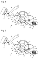
- FIG. 6 is a top plan view of a second embodiment of the invention which, like the first embodiment, is in the form of a stop ring device.
- This second model of stop ring device shares several characteristics with the first stop ring device described in the preceding pages.
- the elements of the second stop ring device which have already been described in relation to the first stop ring device are designated in FIG. figure 6 by the same reference numbers.
- the essential difference between the first and the second embodiment is the rotary control member which, in the figure 6 , is referenced globally 121.
- This rotary control member is arranged to perform steps each corresponding to a pivoting angle ⁇ / N, with N > 1, so that the rotary control member and the magnetic structure that it carries are caused to occupy successively 2N distinct angular positions around their axis of rotation.
- N 4.
- the control member 121 has the general shape of a disk pivoted at its center about an axis of rotation (not referenced).
- the disk carries 2N bipolar magnets (referenced each 133a or 133b), or eight magnets, which are evenly distributed along the periphery of the disk and which have their direction of magnetization oriented radially relative to the axis of rotation of the magnet. control member.
- Four magnets, referenced 133a, have their north pole facing outwards, and the other four magnets (referenced 133b) have their south pole turned outward.
- the rotary control member 121 also comprises a star with 2N branches 149 which is mounted under the disk carrying the magnets.
- the rotary control member 121 is arranged to be driven step-by-step in a given direction of rotation so as to successively occupy a plurality of distinct angular positions around its axis of rotation.
- the control member 121 is provided to occupy exactly 2N distinct stable positions which are regularly spaced by angular steps of 45 °.
- the jumper spring 39 is arranged to cooperate with the eight-pointed star 149, and its two elements are arranged, relative to one another, so that one of the magnets 133a or 133b is still substantially in contact with each other. with respect to the magnet 31 of the switching member 23 when the rotary control member 121 is in any of its stable positions.
- the switching device represented in the figure 6 has a pusher actuation mechanism which is substantially identical to that of the first example.
- This mechanism comprises a pusher 41, a control lever 43 and an intermediate mobile 45.
- the spout 47 of the control lever 43 is arranged to cooperate directly with the star 149 of the rotary control member 121.
- the star 149 has eight branches, it is understood that a pressure on the pusher 41 has the effect to advance the rotary control member by a step of 45 °. Once this step is accomplished, it is the north pole of one of the magnets 133a which will occupy the position vis-à-vis the north pole of the magnet 31.
- FIG. 7 is a top plan view of a third embodiment of the invention which, like the first two embodiments, is in the form of a stop ring device.
- This third model of stop ring device shares many features with the second embodiment.
- the elements of the third stop ring device which have already been described in relation to the first or the second device are designated in FIG. figure 7 by the same reference numbers.
- the differences between the second and third examples of the stop ring device relate to the two magnetic structures respectively forming the rotary control member 221 and the movable member
- the rotary control device shown in FIG. figure 7 comprises a star 149 which has eight branches as in the previous example
- the control member 221 comprises only four bipolar magnets (each referenced 133b). The latter all have their direction of magnetization oriented radially with their south pole turned outwards (their north pole being turned towards the axis of rotation).
- By against the latch 125 of the movable switching member 223 carries two bipolar magnets (referenced 131a and 131b).
- These two magnets have their magnetization directions substantially parallel to each other, but in the opposite direction, so that the south pole of the magnet 131a and the north pole of the magnet 131b are turned in the direction of the control member 221.
- the two magnets 131a and 131b are preferably oriented radially relative to the axis of rotation of the control member and angularly offset by an angular pitch of the control member .
- the rotary control member 221 is arranged to be driven step-by-step in a given direction of rotation so as to successively occupy a plurality of distinct angular positions around its axis of rotation. It will be understood that in the present example, the control member 221 is provided to occupy exactly eight distinct stable positions which are regularly spaced by angular steps of 45 °. It will be further understood that the star 149 with eight branches and the jumper 39 are arranged relative to one another so that at each step, only one of the magnets 133b come to standstill substantially opposite either the south pole of the magnet 131a, or the north pole of the magnet 131b.
- the south pole of a magnet 133b is positioned substantially opposite the north pole of the magnet 131b.
- the magnet 131 b of the switching member 223 is attracted to direction of the control member 221 so that the switching member bears against the stop 28, the movable switching member then being in a first stable position in which the hook 29 is disengaged from the regulator 17, so that the latter is free to turn.
- the switching device represented in the figure 7 has a pusher actuating mechanism which is identical to that shown in FIG. figure 6 .
- a pressure on the pusher 41 has the effect of advancing the rotary control member by a step of 45 ° in the counterclockwise direction.
- the magnet 133b which was opposite the magnet 131b is spaced apart, but another magnet 133b is now positioned facing the south pole of the magnet 131a.
- the magnetic force generated by the interaction between the magnets 133b and 131a pushes the arm of the rocker 125 so that the latter pivots and moves away from the stop 28.
- This pivoting movement causes the lowering of the hook 29 against an external toothing of the regulator 17, which stops it.
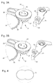
- the attached figures 8 to 11 illustrate a fourth embodiment of the invention which is constituted by a timepiece comprising a rotating bezel and a locking mechanism of the bezel.
- a timepiece comprising a rotating bezel and a locking mechanism of the bezel.
- the figure 8 is a perspective view of a timepiece comprising a rotating bezel (referenced 300) and a locking mechanism of the bezel controlled by a push-button 341.
- the rotating bezel 300 is a watchmaker mechanism that can be in either the locked state or the unlocked state.
- the locking mechanism is an example of a switching device 301 arranged to switch the rotating bezel between a locked state and an unlocked state.
- the rotating bezel 300 has a crenellated lower face and that the locking mechanism comprises a rotary control member which is formed by a shaft 350 mounted to pivot about an axis of rotation substantially perpendicular to the plane of the bezel 300.
- the shaft 350 can for example be pivoted at both ends between the watch case (not shown) and a casing ring (not shown).
- the shaft 350 is further provided with a coaxial pinion 335 and a bipolar magnet 333.
- the magnetization direction of the bipolar magnet 333 is perpendicular to the axis of the magnet. the shaft 350 and the magnet is substantially centered on this axis of rotation.
- the shaft 350 also comprises a non-cylindrical section which has two notches in diametrically opposed positions (a notch visible on the figure 10 is referenced 337). This non-cylindrical section is arranged to cooperate with a jumper spring 339. It plays the same role as the bistable cam 37 of the first embodiment.
- the switching device also comprises two movable switching members (respectively referenced 323a and 323b) which are arranged symmetrically on either side of the shaft 350.
- Each of the movable switching members comprises a rocker (respectively referenced 325a and 325b) pivotally mounted about an axis (respectively referenced 327a and 327b).
- the latches each comprise two arms extending from the pivot axis.
- a first arm is extended by a spout (respectively referenced 329a and 329b) and the second arm carries a bipolar magnet (respectively referenced 331a and 331b).
- the magnetization direction of the magnets is substantially parallel to the pivot plane of the rocker.
- Figures 11A and 11B shows again that the magnet 331a is oriented with its south pole facing the rotary control member and that the magnet 331b is oriented with its north pole facing the control member.
- the switching device 301 shown in the Figures 8 to 11 also has a pusher actuating mechanism.
- This mechanism comprises a pusher 341, a rack 343 having a toothing with triangular teeth, a helical spring 345 and a jumper spring 347.
- the rack 343 is biased against the pinion 335 by the jumper spring 347.
- the triangular teeth of the rack 343 cooperate with the toothing of the pinion 335 to rotate the rotary control member.
- the coil spring 345 pushes the rack 343 towards the pusher.
- the rotary member of control is arranged to be driven step-by-step in a given direction of rotation so as to successively occupy a plurality of distinct angular positions around its axis of rotation.
- the control member is provided to occupy exactly two distinct stable positions which are separated from each other by an angular pitch of 180 °.
- non-cylindrical section of the shaft 350 and the jumper spring 339 are arranged in such a way that the magnetization direction of the magnet 333 is substantially perpendicular to the axis of symmetry between the two movable switching members. 323a and 323b when the control member is in one or other of its two stable angular positions.
- the switching device 301 is arranged so that a step-by-step rotation of the rotary control member causes reciprocating movement of each of the two movable switching members 323a and 323b substantially in a perpendicular plane to the shaft 350 between two radial positions.
- the rotary control member is rotated so that the south pole of the magnet 333 (not visible in the figure) is oriented towards a first 323b of the two movable switching members.
- figure 11A shows the rotary control member rotated so that the south pole of the magnet 333 (not visible in the figure) is oriented towards the movable switching member 323b. The pole north of the magnet 333 is thus turned towards the other movable switching member 323a.
- the magnet 331a of the switching member 323a is oriented with its south pole facing the rotary member, it is also attracted towards the shaft 350 of the rotary control member, so that the second switching member comes to rest in its first radial position in which the spout 329a is also disengaged slots formed on the underside of the rotating bezel 300.
- the rotating bezel is free to rotate. Under these conditions, when a user of the timepiece actuates the pusher 341, the latter pushes the rack 343, so that the triangular teeth of the latter drive the pinion 335 in rotation.
- the non-cylindrical section of the shaft 350 and the jumper spring 339 are arranged so that the control member advances in 180 ° angular increments.
- the actuation of the pusher 341 by the wearer of the watch therefore has the effect of making a half turn to the rotary control member, so that the orientation of the magnet 333 is reversed, the south pole becomes then being oriented in the direction of the movable switching member 323a and the north pole towards the switching member 323b.
- the magnet 331 of the switching member 323a is oriented with its south pole facing the rotary member, it is pushed back by the magnet of the rotary control member, so that the switching member 323a pivots and comes to rest in a second radial position in which the spout 329a cooperates with one of the slots formed on the underside of the rotating bezel 300 as illustrated in FIG. Figure 11B .
- the magnet 331 b of the switching member 323b is oriented with its north pole facing the rotary member, it is also pushed by the magnet of the rotary control member.
- the switching member 323b therefore also comes to be placed in a second radial position in which the spout 329b cooperates with one of the slots formed on the face bottom of the rotating bezel 300 as shown in the Figure 11B .
- the rotating bezel 300 is then locked.
- Variants of this fourth embodiment correspond to arrangements with a plurality of bipolar magnets on the controller or switch member, similarly to the second and third embodiments.
- control member may advantageously comprise, instead of a plurality of bipolar magnets.
- the radial multipolar magnet of circular or annular shape, comprises 2N external magnetic poles (that is to say, oriented towards the outside of this multipolar magnet) which have alternating polarities (that is, that is, alternately south and north), the axis of rotation of the control member passing through the center of the multipole magnet.
- control member is actuated by a user via an actuating device such as a pusher.
- actuating device such as a pusher.
- Other actuation devices known to those skilled in the art can be envisaged.
- These actuating mechanisms may be actuated by a user or, in other embodiments, be automatically and in particular periodically actuated by the timepiece, that is to say by another mechanism of this timepiece which cooperates with the switched mechanism according to the invention.
- the invention has been described in the context of entirely mechanical timepieces. However, the invention can also be applied advantageously to timepieces having electromechanical parts.
- the actuating device of the control member may comprise an electromechanical motor.
Abstract
La pièce d'horlogerie comprend un mécanisme horloger et un dispositif de commutation (1) agencé pour faire commuter ce mécanisme horloger entre deux états. Le dispositif de commutation comprend un organe mobile de commutation (23) et un organe rotatif de commande (21) agencé pour être entrainé pas-à-pas de manière à occuper successivement une pluralité de positions angulaires distinctes autour de son axe de rotation. L'organe mobile de commutation et l'organe rotatif de commande portent respectivement une première structure magnétique (31) et une deuxième structure magnétique (33) agencées de manière que, dans une première position angulaire de l'organe rotatif de commande, une première force magnétique agisse sur l'organe de commutation dans un sens donné, et que, dans une deuxième position angulaire de l'organe rotatif de commande, une deuxième force magnétique agisse sur l'organe de commutation dans le sens opposé.The timepiece comprises a clock mechanism and a switching device (1) arranged to switch this clock mechanism between two states. The switching device comprises a movable switching member (23) and a rotary control member (21) arranged to be driven step-by-step so as to successively occupy a plurality of distinct angular positions around its axis of rotation. The movable switching member and the rotary control member respectively carry a first magnetic structure (31) and a second magnetic structure (33) arranged so that, in a first angular position of the rotary control member, a first magnetic force acts on the switching member in a given direction, and that in a second angular position of the rotary control member, a second magnetic force acts on the switching member in the opposite direction.
Description
La présente invention concerne un dispositif de commutation d'un mécanisme horloger entre deux états fonctionnels.The present invention relates to a switching device of a clock mechanism between two functional states.
Plus particulièrement, la présente invention concerne une pièce d'horlogerie comprenant, d'une part, un mécanisme horloger pouvant commuter entre un premier état et un deuxième état déterminés et, d'autre part, un dispositif de commutation agencé pour faire commuter sur commande le mécanisme horloger entre ses premier et deuxième états. Ce dispositif de commutation comprend un organe mobile de commutation et un organe rotatif de commande qui est agencé pour être entrainé pas-à-pas dans un sens de rotation donné, de manière à occuper successivement une pluralité de positions angulaires autour d'un axe de rotation de cet organe de commande. Le dispositif de commutation est agencé de manière qu'une rotation pas-à-pas de l'organe rotatif de commande provoque un mouvement alternatif de l'organe mobile de commutation, sensiblement dans un plan perpendiculaire audit axe de rotation, de sorte qu'au moins une partie de cet organe mobile de commutation se déplace entre deux positions radiales pour lesquelles le mécanisme horloger est respectivement dans son premier état et son deuxième état.More particularly, the present invention relates to a timepiece comprising, on the one hand, a watch mechanism that can switch between a first state and a second determined state and, on the other hand, a switching device arranged to switch on command the clock mechanism between its first and second states. This switching device comprises a movable switching member and a rotary control member which is arranged to be driven step-by-step in a given direction of rotation, so as to successively occupy a plurality of angular positions around an axis of rotation. rotation of this control member. The switching device is arranged so that a step-by-step rotation of the rotary control member causes reciprocating movement of the movable switching member, substantially in a plane perpendicular to said axis of rotation, so that at least a part of this movable switching member moves between two radial positions for which the clock mechanism is respectively in its first state and its second state.
On connait déjà un grand nombre de pièces d'horlogerie qui correspondent au domaine de l'invention. En particulier, le document
Plus généralement, qu'il s'agisse de montres-chronographes ou d'autre pièces d'horlogerie, les dispositifs de commutation connus comportent généralement un organe rotatif de commande constitué par une came ou une roue à colonnes, et un organe mobile de commutation prenant la forme d'un suiveur de came d'un type ou d'un autre et plus spécifiquement constitué par une bascule ou un levier. Un inconvénient de tels dispositifs de commutation est qu'ils nécessitent tous en principe l'utilisation de ressorts précontraints pour rappeler et maintenir l'organe mobile de commutation contre la came ou la roue à colonnes. Les ressorts horlogers sont encombrants et délicats. Ils sont sujets au vieillissement qui leur fait progressivement perdre en efficacité. Ce vieillissement est en outre considérablement accéléré par les chocs que peut subir la pièce d'horlogerie. D'autre part, en faisant toujours revenir l'organe mobile de commutation en butée contre la came, les ressorts accélèrent l'usure de ces deux composants. Finalement, les ressorts horlogers avec leurs petites dimensions sont assez sensibles aux tolérances, ce qui constitue un problème supplémentaire.More generally, whether chronograph watches or other timepieces, the known switching devices generally comprise a rotary control member consisting of a cam or a column wheel, and a movable switching member. in the form of a cam follower of one type or another and more specifically constituted by a rocker or a lever. A disadvantage of such switching devices is that they all in principle require the use of prestressed springs to return and maintain the movable switching member against the cam or the column wheel. Watch springs are bulky and delicate. They are subject to aging which gradually makes them lose effectiveness. This aging is also considerably accelerated by the shocks that may be experienced by the timepiece. On the other hand, by always returning the mobile switching member in abutment against the cam, the springs accelerate the wear of these two components. Finally, watch springs with their small dimensions are quite sensitive to tolerances, which is an additional problem.
Un but de la présente invention est de remédier aux inconvénients de l'art antérieur qui viennent d'être décrits. L'invention atteint ce but en fournissant une pièce d'horlogerie conforme à la revendication 1 annexée.An object of the present invention is to overcome the disadvantages of the prior art which have just been described. The invention achieves this goal by providing a timepiece according to the appended
Conformément à l'invention, le dispositif de commutation comprend un organe mobile de commutation et un organe rotatif de commande portant respectivement une première structure magnétique et une deuxième structure magnétique agencées de manière à présenter entre elles une interaction magnétique qui permet de faire commuter sur commande le mécanisme horloger entre un premier état et un deuxième état. L'une des première et deuxième structures magnétiques comprend au moins un premier pôle magnétique et l'autre de ces deux structures magnétiques comprend au moins un deuxième pôle magnétique et un troisième pôle magnétique avec des polarités opposées et susceptibles d'interagir successivement avec le premier pôle magnétique. Les première et deuxième structures magnétiques sont agencées de manière que, dans une première position angulaire de l'organe rotatif de commande, une première force magnétique, engendrée par une interaction magnétique entre les premier et deuxième pôles magnétiques, agisse sur l'organe de commutation de manière à amener ce dernier dans une de ses deux positions radiales stables, et que, dans une deuxième position angulaire de l'organe rotatif de commande, une deuxième force magnétique, engendrée par une interaction magnétique entre les premier et troisième pôles magnétiques et ainsi de sens opposé à la première force magnétique, agisse sur l'organe de commutation de manière à rappeler ce dernier dans l'autre de ses deux positions radiales stables.According to the invention, the switching device comprises a mobile switching member and a rotary control member respectively carrying a first magnetic structure and a second magnetic structure arranged so as to have a magnetic interaction between them which makes it possible to switch to command the clock mechanism between a first state and a second state. One of the first and second magnetic structures comprises at least one first magnetic pole and the other of these two magnetic structures comprises at least one second magnetic pole and a third magnetic pole with opposite polarities and capable of interacting successively with the first magnetic pole. magnetic pole. The first and second magnetic structures are arranged so that, in a first angular position of the rotary control member, a first magnetic force, generated by a magnetic interaction between the first and second magnetic poles, acts on the switching member. in order to bring the latter into one of its two stable radial positions, and that, in a second angular position of the rotary control member, a second magnetic force, generated by a magnetic interaction between the first and third magnetic poles and thus in the opposite direction to the first magnetic force, acts on the switching member so as to recall the latter in the other of its two stable radial positions.
On notera que, notamment dans le cas d'une bascule pivotant autour d'un axe parallèle à l'axe de rotation de l'organe rotatif de commande, les deux positions radiales stables concernent plus spécifiquement une partie d'extrémité de l'organe de commutation. Dans le cadre d'un organe de commutation coulissant, c'est l'entier de cet organe qui subit un mouvement de translation dans un plan sensiblement perpendiculaire audit axe de rotation entre deux positions radiales stables de son centre de masse.Note that, particularly in the case of a rocker pivoting about an axis parallel to the axis of rotation of the rotary control member, the two stable radial positions relate more specifically to an end portion of the organ. of commutation. In the context of a sliding switch member, it is the whole of this member which undergoes a translation movement in a plane substantially perpendicular to said axis of rotation between two stable radial positions of its center of mass.
On comprendra que, grâce à ces caractéristiques, il n'est pas nécessaire de prévoir un ressort pour rappeler en permanence l'organe de commutation en direction de l'une des deux positions radiales stables. Ainsi, il en résulte une réduction des contraintes mécaniques et une économie d'énergie mécanique. Un tel système magnétique présente l'avantage d'être un système sans contact capable d'exercer alternativement deux forces avec des sens opposés sur l'organe de commutation.It will be understood that, by virtue of these features, it is not necessary to provide a spring to permanently return the switching member towards one of the two stable radial positions. Thus, it results in a reduction of mechanical stresses and a saving of mechanical energy. Such a magnetic system has the advantage of being a non-contact system capable of alternately exerting two forces with opposite directions on the switching member.
D'autres caractéristiques et avantages de la présente invention apparaîtront à la lecture de la description qui va suivre, donnée uniquement à titre d'exemples non limitatifs, et faite en référence aux dessins annexés dans lesquels :
- les
figures 1 et 2 sont des vues en plan de dessus d'un premier mode de réalisation de l'invention qui est constitué par un premier dispositif stop sonnerie particulier, lafigure 1 montrant ce dispositif en position désengagée alors que lafigure 2 le montre dans sa position engagée dans laquelle il bloque la sonnerie; - la
figure 3A est une vue partielle en perspective du dispositif stop sonnerie desfigures 1 et 2 montrant le dispositif de commutation dans une configuration correspondant à la position engagée représentée à lafigure 2 ;
- la
figure 3B est une vue partielle en perspective du dispositif stop sonnerie desfigures 1 et 2 montrant le dispositif de commutation dans une configuration correspondant à la position désengagée représentée dans lafigure 1 ; - la
figure 4 est une vue schématique en plan d'une came bistable solidaire de l'organe de commande du premier mode de réalisation; - les
figures 5A, 5B et 5C sont des vues en plan de dessus semblables auxfigures 1 et 2 , et qui correspondent à trois instantanés successifs montrant la transition accompagnant l'arrêt automatique de la sonnerie; - la
figure 6 est une vue en plan de dessus d'un deuxième mode de réalisation de l'invention qui est constitué par un deuxième dispositif stop sonnerie particulier; - la
figure 7 est une vue en plan de dessus d'un troisième mode de réalisation de l'invention qui est constitué par un troisième dispositif stop sonnerie particulier; - la
figure 8 est une vue en perspective d'une pièce d'horlogerie comportant une lunette tournante et un mécanisme de verrouillage de la lunette, et correspondant à un quatrième mode de réalisation de l'invention; - la
figure 9 est une vue partielle en plan de dessus montrant plus particulièrement le mécanisme de verrouillage de la lunette de la pièce d'horlogerie de lafigure 8 ; - la
figure 10 est une vue partielle en perspective, depuis le côté fond de la pièce d'horlogerie de lafigure 8 , montrant la lunette tournante et son mécanisme de verrouillage; - la
figure 11A est une vue partielle en plan de dessous montrant le mécanisme de verrouillage de la lunette de la pièce d'horlogerie de lafigure 8 en position désengagée; - la
figure 11B est vue partielle en plan de dessous montrant la lunette tournante de la pièce d'horlogerie de lafigure 8 bloquée par son mécanisme de verrouillage.
- the
Figures 1 and 2 are top plan views of a first embodiment of the invention which is constituted by a first particular ring stop device, thefigure 1 showing this device in disengaged position while thefigure 2 shows it in its engaged position in which it blocks the ringing; - the
figure 3A is a partial perspective view of the stop ring deviceFigures 1 and 2 showing the switching device in a configuration corresponding to the engaged position shown in FIG.figure 2 ;
- the
figure 3B is a partial perspective view of the stop ring deviceFigures 1 and 2 showing the switching device in a configuration corresponding to the disengaged position shown in FIG.figure 1 ; - the
figure 4 is a schematic plan view of a bistable cam integral with the control member of the first embodiment; - the
FIGS. 5A, 5B and 5C are top plan views similar toFigures 1 and 2 , and which correspond to three successive snapshots showing the transition accompanying the automatic stop of the ring; - the
figure 6 is a top plan view of a second embodiment of the invention which is constituted by a second particular ring stop device; - the
figure 7 is a top plan view of a third embodiment of the invention which is constituted by a third particular ring stop device; - the
figure 8 is a perspective view of a timepiece comprising a rotating bezel and a locking mechanism of the bezel, and corresponding to a fourth embodiment of the invention; - the
figure 9 is a partial plan view showing more particularly the locking mechanism of the bezel of the timepiece of thefigure 8 ; - the
figure 10 is a partial perspective view, from the bottom side of the timepiece of thefigure 8 , showing the rotating bezel and its locking mechanism; - the
figure 11A is a partial plan view from below showing the locking mechanism of the bezel of the timepiece of thefigure 8 in disengaged position; - the
Figure 11B is a partial plan view from below showing the rotating bezel of the timepiece of thefigure 8 blocked by its locking mechanism.
Les figures annexées 1 à 5 illustrent un premier mode de réalisation de l'invention qui est constitué par une pièce d'horlogerie comprenant un mécanisme de sonnerie pouvant commuter entre un premier état où la sonnerie est activée et un deuxième état où la sonnerie est stoppée, et comprenant en outre un dispositif stop sonnerie prévu pour faire commuter le mécanisme de sonnerie entre l'état activé et l'état stoppé. Ce dispositif définit donc un interrupteur.The appended figures 1 to 5 illustrate a first embodiment of the invention which is constituted by a timepiece comprising a striking mechanism that can switch between a first state where the ringing is activated and a second state where the ringing is stopped. and further comprising a ring stop device provided for switching the striking mechanism between the activated state and the stopped state. This device therefore defines a switch.
Les
On sait que les pièces d'horlogerie à sonnerie comportent généralement un rouage de sonnerie associé à une source d'énergie constituée par un barillet dans lequel est enroulé un ressort moteur appelé ressort de barillet. Si le barillet était simplement relié à la sonnerie, le désarmage progressif du ressort se traduirait par un ralentissement du rythme de la mélodie au fur et à mesure de son exécution. C'est la raison pour laquelle on a l'habitude de corriger ce phénomène en intégrant un régulateur au rouage qui commande la sonnerie. Ni le barillet, ni le mécanisme de sonnerie proprement dit, ne sont représentés dans les figures. On comprendra toutefois que le barillet est agencé pour entrainer le rouage de sonnerie par l'intermédiaire de la roue 11, et que la sonnerie proprement dite est agencée en aval du régulateur 17, de manière à être entrainée par l'intermédiaire de ce dernier.It is known that timepieces ringing generally comprise a ring gear associated with a power source consists of a cylinder in which is wound a motor spring called mainspring. If the barrel was simply connected to the bell, the progressive disarming of the spring would result in a slower rhythm of the melody as it was performed. This is the reason why we have the habit of correcting this phenomenon by integrating a regulator with the gear that controls the ring. Neither the barrel nor the striking mechanism itself are shown in the figures. However, it will be understood that the barrel is arranged to cause the ring gear by means of the
En se référant toujours aux mêmes figures, on peut voir encore un dispositif de commutation (référencé globalement 1) qui comporte un organe rotatif de de commande 21 et un organe mobile de commutation 23. L'organe de commutation 23 comporte une bascule 25 montée pivotante autour d'un axe 27. La bascule 25 comporte deux bras s'étendant à partir de l'axe de pivotement. Un premier bras de la bascule porte à son extrémité un crochet 29 et le second bras porte un aimant bipolaire 31 dont la direction d'aimantation est sensiblement parallèle au plan de pivotement de la bascule 25. Le dispositif de commutation comporte encore une butée 28 agencée pour coopérer avec le second bras de la bascule de manière à limiter la course de cette dernière.Referring always to the same figures, one can still see a switching device (referenced globally 1) which comprises a
En se référant maintenant aux
Le dispositif de commutation 1 représenté dans les
Conformément à l'invention, le dispositif de commutation est agencé de manière qu'une rotation pas-à-pas de l'organe rotatif de commande 21 provoque un mouvement alternatif de l'organe mobile de commutation 23 sensiblement dans un plan perpendiculaire à l'axe de rotation 22 de l'organe de commande, entre une première position radiale stable et une deuxième position radiale stable. La
Dans la configuration de la
Conformément aux trois premiers modes de réalisation de l'invention qui font l'objet de la présente description, le dispositif de commutation 1 est aussi adapté pour commuter automatiquement le mécanisme de sonnerie, de manière à fonctionner comme limiteur de durée de sonnerie. Ce deuxième mode de fonctionnement du dispositif de commutation 1 sera maintenant décrit en faisant référence aux
Vue de dessus, comme illustré dans les
La
En comparant la
Le dispositif de commutation représenté dans la
La
En comparant la
Conformément à l'invention, l'organe rotatif de commande 221 est agencé pour être entrainé pas-à-pas dans un sens de rotation donné de manière à occuper successivement une pluralité de positions angulaires distinctes autour de son axe de rotation. On comprendra que dans le présent exemple, l'organe de commande 221 est prévu pour occuper exactement huit positions stables distinctes qui sont régulièrement espacées par des pas angulaire de 45°. On comprendra de plus que l'étoile 149 à huit branches et le sautoir 39 sont disposés, l'un relativement à l'autre, de manière à ce qu'à chaque pas, un seul des aimants 133b vienne s'immobiliser sensiblement en regard soit du pôle sud de l'aimant 131 a, soit du pôle nord de l'aimant 131b. En se référant toujours à la
Le dispositif de commutation représenté dans la
Les figures annexées 8 à 11 illustrent un quatrième mode de réalisation de l'invention qui est constitué par une pièce d'horlogerie comportant une lunette tournante et un mécanisme de verrouillage de la lunette. On sait que les montres de plongée sont le plus souvent équipées d'une lunette tournante. Cette lunette a pour fonction principale de marquer la position où se trouvait l'aiguille des minutes au début de la plongée. Le plongeur peut ensuite à tout moment savoir depuis combien de temps il est sous l'eau en observant la distance parcourue par l'aiguille des minutes depuis la position indexée par la lunette tournante. Dans le but d'éviter toute modification accidentelle de la position angulaire de la lunette tournante en cours de plongée, on a l'habitude d'équiper la lunette tournante d'un mécanisme de verrouillage.The attached figures 8 to 11 illustrate a fourth embodiment of the invention which is constituted by a timepiece comprising a rotating bezel and a locking mechanism of the bezel. We know that diving watches are most often equipped with a rotating bezel. The main function of this telescope is to mark the position of the minute hand at the beginning of the dive. The diver can then at any time know how long he has been underwater by observing the distance traveled by the minute hand from the position indexed by the rotating bezel. In order to avoid any accidental modification of the angular position of the rotating bezel during a dive, it is customary to equip the rotating bezel with a locking mechanism.
La
En se référant plus particulièrement à la
Dans le mode de réalisation illustré, le dispositif de commutation comporte également deux organes mobiles de commutation (respectivement référencés 323a et 323b) qui sont arrangés symétriquement de part et d'autre de l'arbre 350. Chacun des organes mobiles de commutation comporte une bascule (respectivement référencées 325a et 325b) montée pivotante autour d'un axe (respectivement référencés 327a et 327b). Les bascules comportent chacune deux bras s'étendant à partir de l'axe de pivotement. Un premier bras se prolonge par un bec (respectivement référencés 329a et 329b) et le second bras porte un aimant bipolaire (respectivement référencés 331 a et 331 b). La direction d'aimantation des aimants est sensiblement parallèle au plan de pivotement de la bascule. Un examen plus détaillé (
Comme déjà mentionné, le dispositif de commutation 301 représenté dans les
Le fonctionnement du dispositif de commutation 301 va maintenant être décrit en se référant plus particulièrement aux
Des variantes de ce quatrième mode de réalisation correspondent à des agencements avec plusieurs aimants bipolaires sur l'organe de commande ou sur l'organe de commutation, de manière similaire aux deuxième et troisième modes de réalisation.Variants of this fourth embodiment correspond to arrangements with a plurality of bipolar magnets on the controller or switch member, similarly to the second and third embodiments.
On remarquera que dans les divers modes de réalisation avec des organes de commande comprenant au moins quatre pôles magnétiques interagissant avec l'organe de commutation, l'organe de commande peut avantageusement comprendre, en lieu et place d'une pluralité d'aimants bipolaires. Dans une variante particulière, l'aimant multipolaire radial, de forme circulaire ou annulaire, comporte 2N pôles magnétiques externes (c'est-à-dire orientés vers l'extérieur de cet aimant multipolaire) qui présentent des polarités alternées (c'est-à-dire alternativement sud et nord), l'axe de rotation de l'organe de commande passant par le centre de l'aimant multipolaire.It will be noted that in the various embodiments with control members comprising at least four magnetic poles interacting with the switching member, the control member may advantageously comprise, instead of a plurality of bipolar magnets. In a particular variant, the radial multipolar magnet, of circular or annular shape, comprises 2N external magnetic poles (that is to say, oriented towards the outside of this multipolar magnet) which have alternating polarities (that is, that is, alternately south and north), the axis of rotation of the control member passing through the center of the multipole magnet.
On notera que d'autres applications horlogères sont prévues dans le cadre de l'invention, notamment un dispositif d'embrayage latéral, permettant de transmettre momentanément un couple, ou un dispositif de commutation d'un mécanisme de chronographe du type décrit précédemment dans la section relative à l'art antérieur, dans lequel la roue à colonnes et la/les came(s) associée(s) sont remplacées par un dispositif de commutation selon l'invention. On remarquera par ailleurs que la présente invention s'applique aussi à des réalisations avec plusieurs organes de commutation associés à un même organe de commande.It will be noted that other horological applications are provided within the scope of the invention, in particular a lateral clutch device, making it possible to momentarily transmit a torque, or a switching device of a chronograph mechanism of the type previously described in FIG. section relating to the prior art, in which the column wheel and the cam (s) associated (s) associated (s) are replaced by a switching device according to the invention. It will also be noted that the present invention also applies to embodiments with a plurality of switching members associated with the same control member.
Dans les modes de réalisation décrits, l'organe de commande est actionné par un utilisateur via un dispositif d'actionnement comme un poussoir. D'autres dispositifs d'actionnement connus de l'homme du métier peuvent être envisagés. Ces mécanismes d'actionnement peuvent être actionnés par un utilisateur ou, dans d'autres modes de réalisation, être automatiquement et notamment périodiquement actionnés par la pièce d'horlogerie, c'est-à-dire par un autre mécanisme de cette pièce d'horlogerie qui coopère avec le mécanisme commuté selon l'invention.In the embodiments described, the control member is actuated by a user via an actuating device such as a pusher. Other actuation devices known to those skilled in the art can be envisaged. These actuating mechanisms may be actuated by a user or, in other embodiments, be automatically and in particular periodically actuated by the timepiece, that is to say by another mechanism of this timepiece which cooperates with the switched mechanism according to the invention.
Finalement, l'invention a été décrite dans le cadre de pièces d'horlogerie entièrement mécanique. Toutefois, l'invention peut s'appliquer aussi avantageusement à des pièces d'horlogerie ayant des parties électromécaniques. Ainsi, le dispositif d'actionnement de l'organe de commande peut comprendre un moteur électromécanique.Finally, the invention has been described in the context of entirely mechanical timepieces. However, the invention can also be applied advantageously to timepieces having electromechanical parts. Thus, the actuating device of the control member may comprise an electromechanical motor.
Claims (10)
Priority Applications (6)
| Application Number | Priority Date | Filing Date | Title |
|---|---|---|---|
| EP16177617.4A EP3264199A1 (en) | 2016-07-01 | 2016-07-01 | Timepiece comprising a switching device of a clockwork mechanism |
| EP17172015.4A EP3264200B1 (en) | 2016-07-01 | 2017-05-19 | Timepiece comprising a switching device of a clockwork mechanism |
| US15/614,884 US10037010B2 (en) | 2016-07-01 | 2017-06-06 | Timepiece comprising a device for switching a timekeeping mechanism |
| JP2017114963A JP6594929B2 (en) | 2016-07-01 | 2017-06-12 | Timer with device for switching timing mechanism |
| CN201710526886.7A CN107561914B (en) | 2016-07-01 | 2017-06-30 | Clock and watch including the device for switching time movement |
| HK18108132.2A HK1248837A1 (en) | 2016-07-01 | 2018-06-25 | Timepiece comprising a device for switching a timekeeping mechanism |
Applications Claiming Priority (1)
| Application Number | Priority Date | Filing Date | Title |
|---|---|---|---|
| EP16177617.4A EP3264199A1 (en) | 2016-07-01 | 2016-07-01 | Timepiece comprising a switching device of a clockwork mechanism |
Publications (1)
| Publication Number | Publication Date |
|---|---|
| EP3264199A1 true EP3264199A1 (en) | 2018-01-03 |
Family
ID=56321828
Family Applications (2)
| Application Number | Title | Priority Date | Filing Date |
|---|---|---|---|
| EP16177617.4A Withdrawn EP3264199A1 (en) | 2016-07-01 | 2016-07-01 | Timepiece comprising a switching device of a clockwork mechanism |
| EP17172015.4A Active EP3264200B1 (en) | 2016-07-01 | 2017-05-19 | Timepiece comprising a switching device of a clockwork mechanism |
Family Applications After (1)
| Application Number | Title | Priority Date | Filing Date |
|---|---|---|---|
| EP17172015.4A Active EP3264200B1 (en) | 2016-07-01 | 2017-05-19 | Timepiece comprising a switching device of a clockwork mechanism |
Country Status (5)
| Country | Link |
|---|---|
| US (1) | US10037010B2 (en) |
| EP (2) | EP3264199A1 (en) |
| JP (1) | JP6594929B2 (en) |
| CN (1) | CN107561914B (en) |
| HK (1) | HK1248837A1 (en) |
Families Citing this family (3)
| Publication number | Priority date | Publication date | Assignee | Title |
|---|---|---|---|---|
| EP3327518B1 (en) * | 2016-11-29 | 2020-03-18 | Montres Breguet S.A. | Timepiece comprising a switching device of a clockwork mechanism |
| EP3540524B1 (en) * | 2018-03-13 | 2022-02-16 | Montres Breguet S.A. | Governed jumping display mechanism in a timepiece |
| CH714798B1 (en) * | 2018-03-19 | 2022-03-31 | Hublot Sa Geneve | Chronograph mechanism for a timepiece. |
Citations (4)
| Publication number | Priority date | Publication date | Assignee | Title |
|---|---|---|---|---|
| FR1090564A (en) * | 1953-09-17 | 1955-03-31 | Hatot Leon Ets | Improvements to time mechanisms and similar devices |
| FR1276734A (en) * | 1960-10-12 | 1961-11-24 | Magnetic drive and linkage system and applications in mechanical and electrical watchmaking | |
| US3462942A (en) * | 1962-11-03 | 1969-08-26 | Us Time Corp The | Dial train drive |
| EP2602675A1 (en) | 2011-12-08 | 2013-06-12 | ETA SA Manufacture Horlogère Suisse | Timepiece movement comprising a chronograph mechanism with column wheel |
Family Cites Families (8)
| Publication number | Priority date | Publication date | Assignee | Title |
|---|---|---|---|---|
| JPS6080379U (en) * | 1983-09-28 | 1985-06-04 | カシオ計算機株式会社 | Electronic clock time adjustment device |
| DE4010837C1 (en) * | 1990-04-04 | 1991-07-25 | Manufacture Jaeger-Le Coultre S.A., Le Sentier, Ch | |
| JPH0514974U (en) * | 1991-08-03 | 1993-02-26 | シチズン時計株式会社 | Rotating structure of inner register ring |
| ATE492837T1 (en) * | 2008-06-17 | 2011-01-15 | Montres Breguet Sa | DISPLAY DEVICE FOR DISPLAYING ONE OR THE OTHER OF TWO DIFFERENT INFORMATION WITH THE SAME DISPLAY ELEMENT OF A CLOCK |
| EP2463732B1 (en) * | 2010-12-10 | 2016-03-30 | Montres Breguet SA | Chiming mechanism of a watch or a music box |
| CH707582B1 (en) * | 2013-02-04 | 2018-12-14 | Montres Breguet Sa | Watch sub-assembly with magnetic or electrostatic pivoting. |
| EP3185080B1 (en) * | 2015-12-22 | 2019-12-18 | Montres Breguet S.A. | Timepiece mechanism comprising a pivoting member provided with magnetic return means |
| EP3264198B1 (en) * | 2016-07-01 | 2020-01-15 | Montres Breguet S.A. | Timepiece comprising a device for switching a mechanism of said timepiece |
-
2016
- 2016-07-01 EP EP16177617.4A patent/EP3264199A1/en not_active Withdrawn
-
2017
- 2017-05-19 EP EP17172015.4A patent/EP3264200B1/en active Active
- 2017-06-06 US US15/614,884 patent/US10037010B2/en active Active
- 2017-06-12 JP JP2017114963A patent/JP6594929B2/en active Active
- 2017-06-30 CN CN201710526886.7A patent/CN107561914B/en active Active
-
2018
- 2018-06-25 HK HK18108132.2A patent/HK1248837A1/en unknown
Patent Citations (4)
| Publication number | Priority date | Publication date | Assignee | Title |
|---|---|---|---|---|
| FR1090564A (en) * | 1953-09-17 | 1955-03-31 | Hatot Leon Ets | Improvements to time mechanisms and similar devices |
| FR1276734A (en) * | 1960-10-12 | 1961-11-24 | Magnetic drive and linkage system and applications in mechanical and electrical watchmaking | |
| US3462942A (en) * | 1962-11-03 | 1969-08-26 | Us Time Corp The | Dial train drive |
| EP2602675A1 (en) | 2011-12-08 | 2013-06-12 | ETA SA Manufacture Horlogère Suisse | Timepiece movement comprising a chronograph mechanism with column wheel |
Also Published As
| Publication number | Publication date |
|---|---|
| EP3264200B1 (en) | 2020-01-01 |
| EP3264200A1 (en) | 2018-01-03 |
| JP2018004629A (en) | 2018-01-11 |
| HK1248837A1 (en) | 2018-10-19 |
| JP6594929B2 (en) | 2019-10-23 |
| US20180004167A1 (en) | 2018-01-04 |
| CN107561914B (en) | 2019-07-05 |
| CN107561914A (en) | 2018-01-09 |
| US10037010B2 (en) | 2018-07-31 |
Similar Documents
| Publication | Publication Date | Title |
|---|---|---|
| EP2453322B1 (en) | Fast time quantity indicator corrector for a timepiece | |
| EP2410388B1 (en) | Time piece with double display | |
| EP3407144B1 (en) | Timepiece comprising a device for locking a pusher | |
| EP2073076B1 (en) | Alarm clock control mechanism | |
| EP2541346B1 (en) | Device for resetting a component indicating a time-related magnitude to a predetermined position | |
| EP2136271B1 (en) | Display device for displaying one of two different indications using the same indicating element of a timepiece | |
| EP1373991A1 (en) | Chronograph with two rotational directions | |
| EP3264200B1 (en) | Timepiece comprising a switching device of a clockwork mechanism | |
| EP3584643B1 (en) | Instantaneous command device for date display of timepieces | |
| WO2011160970A1 (en) | Clockwork movement exhibiting chronograph and countdown functions | |
| EP1962152A1 (en) | Security device for display | |
| CH703470A2 (en) | On-demand additional display mechanism for e.g. hour, measurement and/or generation movement in timepiece, has pusher controlling resetting of display by disengaging control and by indexing control of original position of peripheral core | |
| FR2097126A1 (en) | ||
| CA2059133C (en) | Control device for the timed release of a mechanism | |
| CH712669A2 (en) | Timepiece comprising a switching device of a clock mechanism. | |
| EP1857890B1 (en) | Device for triggering a pulse | |
| EP2802945A1 (en) | Clockwork movement indicating mechanism that acts in response to a request for information | |
| WO2009144265A1 (en) | Display device | |
| CH712012A1 (en) | Watch movement with jumping display mechanism. | |
| EP3882718A1 (en) | Device for correction of at least one complication module of a timepiece | |
| WO2007060150A2 (en) | Clockwork movement | |
| CH708902A2 (en) | animated timepiece. | |
| EP4060428B1 (en) | Driving mechanism for timepiece movement, in particular a chronograph mechanism comprising such a driving mechanism | |
| EP3800512B1 (en) | Device for on-demand display for a clock piece | |
| EP3686694B1 (en) | Alarm clock mechanism and timepiece comprising such a mechanism |
Legal Events
| Date | Code | Title | Description |
|---|---|---|---|
| PUAI | Public reference made under article 153(3) epc to a published international application that has entered the european phase |
Free format text: ORIGINAL CODE: 0009012 |
|
| AK | Designated contracting states |
Kind code of ref document: A1 Designated state(s): AL AT BE BG CH CY CZ DE DK EE ES FI FR GB GR HR HU IE IS IT LI LT LU LV MC MK MT NL NO PL PT RO RS SE SI SK SM TR |
|
| AX | Request for extension of the european patent |
Extension state: BA ME |
|
| STAA | Information on the status of an ep patent application or granted ep patent |
Free format text: STATUS: THE APPLICATION HAS BEEN WITHDRAWN |
|
| 18W | Application withdrawn |
Effective date: 20180626 |