EP3264153A1 - Light sheet microscope and control method for light sheet microscope - Google Patents
Light sheet microscope and control method for light sheet microscope Download PDFInfo
- Publication number
- EP3264153A1 EP3264153A1 EP17177377.3A EP17177377A EP3264153A1 EP 3264153 A1 EP3264153 A1 EP 3264153A1 EP 17177377 A EP17177377 A EP 17177377A EP 3264153 A1 EP3264153 A1 EP 3264153A1
- Authority
- EP
- European Patent Office
- Prior art keywords
- light sheet
- objective
- light
- sample
- controller
- Prior art date
- Legal status (The legal status is an assumption and is not a legal conclusion. Google has not performed a legal analysis and makes no representation as to the accuracy of the status listed.)
- Granted
Links
- 238000000034 method Methods 0.000 title claims description 78
- 230000003287 optical effect Effects 0.000 claims abstract description 102
- 238000005286 illumination Methods 0.000 claims abstract description 15
- 230000008569 process Effects 0.000 claims description 54
- 238000011156 evaluation Methods 0.000 claims description 30
- 230000001678 irradiating effect Effects 0.000 claims description 3
- 239000011521 glass Substances 0.000 description 10
- 230000007246 mechanism Effects 0.000 description 6
- 230000008859 change Effects 0.000 description 4
- 238000003860 storage Methods 0.000 description 4
- 238000007654 immersion Methods 0.000 description 3
- 238000012937 correction Methods 0.000 description 2
- 238000009826 distribution Methods 0.000 description 2
- 238000012545 processing Methods 0.000 description 2
- 241000252212 Danio rerio Species 0.000 description 1
- 230000001133 acceleration Effects 0.000 description 1
- 230000008901 benefit Effects 0.000 description 1
- 238000004364 calculation method Methods 0.000 description 1
- 210000004027 cell Anatomy 0.000 description 1
- 230000000295 complement effect Effects 0.000 description 1
- 210000004748 cultured cell Anatomy 0.000 description 1
- BFMYDTVEBKDAKJ-UHFFFAOYSA-L disodium;(2',7'-dibromo-3',6'-dioxido-3-oxospiro[2-benzofuran-1,9'-xanthene]-4'-yl)mercury;hydrate Chemical compound O.[Na+].[Na+].O1C(=O)C2=CC=CC=C2C21C1=CC(Br)=C([O-])C([Hg])=C1OC1=C2C=C(Br)C([O-])=C1 BFMYDTVEBKDAKJ-UHFFFAOYSA-L 0.000 description 1
- 238000007876 drug discovery Methods 0.000 description 1
- 238000005562 fading Methods 0.000 description 1
- 102000034287 fluorescent proteins Human genes 0.000 description 1
- 108091006047 fluorescent proteins Proteins 0.000 description 1
- 230000004907 flux Effects 0.000 description 1
- 230000006870 function Effects 0.000 description 1
- 238000010191 image analysis Methods 0.000 description 1
- 238000004519 manufacturing process Methods 0.000 description 1
- 230000007721 medicinal effect Effects 0.000 description 1
- 229910044991 metal oxide Inorganic materials 0.000 description 1
- 150000004706 metal oxides Chemical class 0.000 description 1
- 238000012986 modification Methods 0.000 description 1
- 230000004048 modification Effects 0.000 description 1
- 239000013307 optical fiber Substances 0.000 description 1
- 210000002220 organoid Anatomy 0.000 description 1
- 238000012216 screening Methods 0.000 description 1
- 239000004065 semiconductor Substances 0.000 description 1
- 230000000638 stimulation Effects 0.000 description 1
Images


Classifications
-
- G—PHYSICS
- G02—OPTICS
- G02B—OPTICAL ELEMENTS, SYSTEMS OR APPARATUS
- G02B21/00—Microscopes
- G02B21/0004—Microscopes specially adapted for specific applications
- G02B21/002—Scanning microscopes
- G02B21/0024—Confocal scanning microscopes (CSOMs) or confocal "macroscopes"; Accessories which are not restricted to use with CSOMs, e.g. sample holders
- G02B21/0032—Optical details of illumination, e.g. light-sources, pinholes, beam splitters, slits, fibers
-
- G—PHYSICS
- G01—MEASURING; TESTING
- G01J—MEASUREMENT OF INTENSITY, VELOCITY, SPECTRAL CONTENT, POLARISATION, PHASE OR PULSE CHARACTERISTICS OF INFRARED, VISIBLE OR ULTRAVIOLET LIGHT; COLORIMETRY; RADIATION PYROMETRY
- G01J1/00—Photometry, e.g. photographic exposure meter
- G01J1/42—Photometry, e.g. photographic exposure meter using electric radiation detectors
- G01J1/44—Electric circuits
-
- G—PHYSICS
- G01—MEASURING; TESTING
- G01N—INVESTIGATING OR ANALYSING MATERIALS BY DETERMINING THEIR CHEMICAL OR PHYSICAL PROPERTIES
- G01N21/00—Investigating or analysing materials by the use of optical means, i.e. using sub-millimetre waves, infrared, visible or ultraviolet light
- G01N21/62—Systems in which the material investigated is excited whereby it emits light or causes a change in wavelength of the incident light
- G01N21/63—Systems in which the material investigated is excited whereby it emits light or causes a change in wavelength of the incident light optically excited
- G01N21/64—Fluorescence; Phosphorescence
- G01N21/6428—Measuring fluorescence of fluorescent products of reactions or of fluorochrome labelled reactive substances, e.g. measuring quenching effects, using measuring "optrodes"
-
- G—PHYSICS
- G01—MEASURING; TESTING
- G01N—INVESTIGATING OR ANALYSING MATERIALS BY DETERMINING THEIR CHEMICAL OR PHYSICAL PROPERTIES
- G01N21/00—Investigating or analysing materials by the use of optical means, i.e. using sub-millimetre waves, infrared, visible or ultraviolet light
- G01N21/62—Systems in which the material investigated is excited whereby it emits light or causes a change in wavelength of the incident light
- G01N21/63—Systems in which the material investigated is excited whereby it emits light or causes a change in wavelength of the incident light optically excited
- G01N21/64—Fluorescence; Phosphorescence
- G01N21/645—Specially adapted constructive features of fluorimeters
- G01N21/6456—Spatial resolved fluorescence measurements; Imaging
- G01N21/6458—Fluorescence microscopy
-
- G—PHYSICS
- G02—OPTICS
- G02B—OPTICAL ELEMENTS, SYSTEMS OR APPARATUS
- G02B21/00—Microscopes
- G02B21/0004—Microscopes specially adapted for specific applications
- G02B21/002—Scanning microscopes
- G02B21/0024—Confocal scanning microscopes (CSOMs) or confocal "macroscopes"; Accessories which are not restricted to use with CSOMs, e.g. sample holders
- G02B21/0052—Optical details of the image generation
- G02B21/006—Optical details of the image generation focusing arrangements; selection of the plane to be imaged
-
- G—PHYSICS
- G02—OPTICS
- G02B—OPTICAL ELEMENTS, SYSTEMS OR APPARATUS
- G02B21/00—Microscopes
- G02B21/0004—Microscopes specially adapted for specific applications
- G02B21/002—Scanning microscopes
- G02B21/0024—Confocal scanning microscopes (CSOMs) or confocal "macroscopes"; Accessories which are not restricted to use with CSOMs, e.g. sample holders
- G02B21/0052—Optical details of the image generation
- G02B21/0076—Optical details of the image generation arrangements using fluorescence or luminescence
-
- G—PHYSICS
- G02—OPTICS
- G02B—OPTICAL ELEMENTS, SYSTEMS OR APPARATUS
- G02B21/00—Microscopes
- G02B21/06—Means for illuminating specimens
-
- G—PHYSICS
- G02—OPTICS
- G02B—OPTICAL ELEMENTS, SYSTEMS OR APPARATUS
- G02B21/00—Microscopes
- G02B21/36—Microscopes arranged for photographic purposes or projection purposes or digital imaging or video purposes including associated control and data processing arrangements
- G02B21/365—Control or image processing arrangements for digital or video microscopes
- G02B21/367—Control or image processing arrangements for digital or video microscopes providing an output produced by processing a plurality of individual source images, e.g. image tiling, montage, composite images, depth sectioning, image comparison
-
- G—PHYSICS
- G01—MEASURING; TESTING
- G01J—MEASUREMENT OF INTENSITY, VELOCITY, SPECTRAL CONTENT, POLARISATION, PHASE OR PULSE CHARACTERISTICS OF INFRARED, VISIBLE OR ULTRAVIOLET LIGHT; COLORIMETRY; RADIATION PYROMETRY
- G01J1/00—Photometry, e.g. photographic exposure meter
- G01J1/42—Photometry, e.g. photographic exposure meter using electric radiation detectors
- G01J1/44—Electric circuits
- G01J2001/4446—Type of detector
- G01J2001/4453—PMT
-
- G—PHYSICS
- G01—MEASURING; TESTING
- G01N—INVESTIGATING OR ANALYSING MATERIALS BY DETERMINING THEIR CHEMICAL OR PHYSICAL PROPERTIES
- G01N21/00—Investigating or analysing materials by the use of optical means, i.e. using sub-millimetre waves, infrared, visible or ultraviolet light
- G01N21/62—Systems in which the material investigated is excited whereby it emits light or causes a change in wavelength of the incident light
- G01N21/63—Systems in which the material investigated is excited whereby it emits light or causes a change in wavelength of the incident light optically excited
- G01N21/64—Fluorescence; Phosphorescence
- G01N21/6428—Measuring fluorescence of fluorescent products of reactions or of fluorochrome labelled reactive substances, e.g. measuring quenching effects, using measuring "optrodes"
- G01N2021/6439—Measuring fluorescence of fluorescent products of reactions or of fluorochrome labelled reactive substances, e.g. measuring quenching effects, using measuring "optrodes" with indicators, stains, dyes, tags, labels, marks
-
- G—PHYSICS
- G01—MEASURING; TESTING
- G01N—INVESTIGATING OR ANALYSING MATERIALS BY DETERMINING THEIR CHEMICAL OR PHYSICAL PROPERTIES
- G01N21/00—Investigating or analysing materials by the use of optical means, i.e. using sub-millimetre waves, infrared, visible or ultraviolet light
- G01N21/62—Systems in which the material investigated is excited whereby it emits light or causes a change in wavelength of the incident light
- G01N21/63—Systems in which the material investigated is excited whereby it emits light or causes a change in wavelength of the incident light optically excited
- G01N21/64—Fluorescence; Phosphorescence
- G01N21/645—Specially adapted constructive features of fluorimeters
- G01N2021/6463—Optics
-
- G—PHYSICS
- G01—MEASURING; TESTING
- G01N—INVESTIGATING OR ANALYSING MATERIALS BY DETERMINING THEIR CHEMICAL OR PHYSICAL PROPERTIES
- G01N2201/00—Features of devices classified in G01N21/00
- G01N2201/06—Illumination; Optics
- G01N2201/061—Sources
- G01N2201/06113—Coherent sources; lasers
- G01N2201/0612—Laser diodes
Definitions
- the disclosure of the present invention is related to a light sheet microscope and a control method for a light sheet microscope.
- a technique in which a sample is irradiated with a laser beam from a direction that is orthogonal to the optical axis of the objective so as to form, in the sample, a light sheet orthogonal to the optical axis of the objective.
- a light sheet microscope using this technique is disclosed in for example U.S. Unexamined Patent Application Publication No 2015/0286042 and International Publication Pamphlet No. WO2015/184124 .
- Light sheet microscopes can generate an excellent 3-D image of a sample at a high speed with suppressed fading of fluorescence, which is a great advantage.
- purposes of this technique are not limited to the obtainment of a 3-D image of a creature such as zebrafish that is labeled with fluorescent protein as a target molecule.
- This technique draws attention also as a technique aiming to be applied to so-called “drug-discovery screening", in which medical effects are evaluated by obtaining a 3-D image of a 3-D cultured cell such as spheroid or organoid and using an image analysis technique. This technique is expected to be applied to a wide range of applications.
- a light sheet microscope In order to obtain a 3-D image of a sample, a light sheet microscope usually obtains a plurality of cross-sectional images while relatively moving the light sheet and the sample along the observation optical axis (optical axis of the objective). In many cases, the light sheet and the objective are fixed after the light sheet is set to be formed on the focal plane of the objective. Then, a plurality of cross-sectional images are obtained by sequentially moving the sample in the optical axis direction.
- a change of an observed location of the sample i.e., a plane on which the light sheet is formed in the sample, which will be referred to as a light sheet plane
- a component ratio of media between the objective and the light sheet plane e.g., the ratio between the air, the culture solution and the inside of the sample.
- the optical path length between the objective and the light sheet plane changes.
- the focal plane of the objective moves in the optical axis directions and the focal plane of the objective does not coincide with the light sheet plane.
- the refractive-index distribution in the sample also changes the movement amount of the focal plane.
- the more the optical resolution of a 3-D image is to be increased i.e., the more the numerical aperture of the objective is to be increased by reducing the thickness of the light sheet, the greater the influence caused by this difference becomes because the shallower the focal depth is.
- U.S. Unexamined Patent Application Publication No 2015/0286042 and International Publication Pamphlet No. WO 2015/184124 above disclose a technique that performs calibration by using the observation target before observation so as to generate data for correcting a difference of the focal plane of the objective. Using this technique can suppress a difference between the focal plane of the objective and the light sheet plane to some extent.
- a light sheet microscope includes an objective, an illumination optical system that irradiates sample with a light sheet from a direction that is different from an optical axis direction of the objective, first adjustment means for adjusting a relative position between a light sheet plane on which the light sheet is formed and the objective in the optical axis direction of the objective, second adjustment means for adjusting a relative position between the light sheet plane and the sample in the optical axis direction of the objective, and a controller that controls the first adjustment means on the basis of light that is from the light sheet plane and that is detected via the objective when a relative position between the light sheet plane and the sample is changed by the second adjustment means.
- a control method for a light sheet microscope having an objective includes irradiating sample with a light sheet from a direction that is different from an optical axis direction of the objective, adjusting a relative position between a light sheet plane on which the light sheet is formed and the sample in the optical axis direction of the objective, adjusting a relative position between the light sheet plane and the objective in the optical axis direction of the objective on the basis of light that is from the light sheet plane and that is detected via the objective when a relative position between the light sheet plane and the sample is adjusted, and obtaining an image of the sample that is irradiated with the light sheet.
- An aspect of the present invention can provide a light sheet microscope and a control method for a light sheet microscope that can make the focal plane of an objective coincide with a light sheet plane swiftly and highly accurately.
- FIG. 1 exemplifies a configuration of a light sheet microscope 100 according to the present embodiment.
- the light sheet microscope 100 is a apparatus that obtains a cross-sectional image of sample S immersed in medium M such as culture solution, transparentization solution, etc.
- Sample S is for example a biological cell that was labeled by fluorochrome.
- Sample S is contained in for example a sample container 5 such as a cuvette etc. mounted on a stage 6.
- the light sheet microscope 100 includes a laser 1, an optical fiber 2, a light sheet illumination optical system 4, the stage 6, a dry objective 7, Z drive unit 8, a tube lens 9, a dichroic mirror 10, an emission filter 11 and an image pickup device 12.
- the light sheet illumination optical system 4 includes for example a collector lens and a cylindrical lens, and irradiates sample S with a light sheet from a direction different from the optical axis direction of the objective 7. More specifically, the light sheet illumination optical system 4 is arranged so that the emission optical axis of the light sheet illumination optical system 4 is roughly orthogonal to the optical axis of the objective 7.
- the light sheet illumination optical system 4 is configured to irradiate sample S with light sheet LS from a direction that is roughly orthogonal to the optical axis of the objective 7.
- a light sheet is illumination light that forms a sheet-shaped illumination area.
- Light sheet LS has a sheet-like shape that is thin in the optical axis directions of the objective 7 in sample S.
- "roughly orthogonal" refers to a range that may be considered by those skilled in the art as an error in setting or manufacturing from the orthogonal state.
- the stage 6 is an electric stage that moves in the optical axis directions of the objective 7.
- the stage 6 is second adjustment means for adjusting the relative position (i.e. relative distance) between a light sheet plane and sample S in the optical axis directions of the objective 7.
- the movement of the stage 6 is controlled by a controller 20, which will be explained later.
- the Z drive unit 8 is an electric unit that moves the objective 7 in the optical axis directions of the objective 7.
- the Z drive unit 8 is first adjustment means for adjusting the relative position (i.e. relative distance) between a light sheet plane on which light sheet LS is formed and the objective 7 in the optical axis directions of the objective 7. Movements of the objective 7 via the Z drive unit 8 are controlled by the controller 20, which will be described later.
- the dichroic mirror 10 reflects a laser beam so as to split the beam into a laser beam and fluorescence.
- the emission filter 11 shields a laser beam and transmits fluorescence.
- the dichroic mirror 10 and the emission filter 11 limit the entrance of a laser beam to the image pickup device 12.
- the image pickup device 12 obtains, via the objective 7, an image of sample S that is irradiated with light sheet LS.
- the image pickup device 12 is for example a digital camera having a 2-D image sensor such as a CCD (Charge Coupled Device, a CMOS (Complementary Metal Oxide Semiconductor), etc.
- the image pickup device 12 has light-receiving surface S1, and is arranged in such a manner that the front-side focal position of the objective 7 is projected on the light-receiving surface S1.
- Position P1 on light-receiving surface S1 shown in FIG. 1 is the position at which the front-side focal position of the objective 7 is projected, i.e., the position that is optically conjugate with the front-side focal position of the objective 7.
- the light sheet microscope 100 further includes a beam splitter 13, two light shielding plates (pinhole plates 14 and 16) and two photodetectors (photodetectors 15 and 17) in the reflection optical path of the dichroic mirror 10 (the optical path branching, by the dichroic mirror 10, from the optical path between the image pickup device 12 and the objective 7).
- the beam splitter 13 splits the laser beam reflected by the dichroic mirror 10 at a ratio of 50: 50.
- the pinhole plate 14 and the photodetector 15 are arranged in one of the optical paths branched by the beam splitter 13.
- the pinhole plate 16 and the photodetector 17 are arranged on the other of the optical paths branched by the beam splitter 13.
- the pinhole plate 14 is a first light shielding plate having an opening, and is arranged on the far side of position P2 at which the front-side focal position of the objective 7 is projected.
- the pinhole plate 16 is a second light shielding plate having an opening, and is arranged on the near side of position P3 at which the front-side focal position of the objective 7 is projected.
- Positions P2 and P3 are positions that are optically conjugate with the front-side focal position of the objective 7, and are, in other words, positions corresponding to the light-receiving surface S1 (position P1) of the image pickup device 12.
- positions P2 and P3 may respectively be referred to also as reference positions, as necessary.
- “near side” means a near side with respect to the traveling direction of the light
- far side means a far side with respect to the traveling direction of the light.
- the photodetector 15 is a first photodetector that detects light that is from the light sheet plane and that passed through the pinhole plate 14, and detects a laser beam in a dedicated manner.
- the photodetector 17 is a second photodetector that detects light that is from the light sheet plane and that passed through the pinhole plate 16, and detects a laser beam in a dedicated manner.
- the photodetector 15 and the photodetector 17 are for example Photomultiplier Tubes (PMTs), and output a signal in accordance with a detected light amount.
- PMTs Photomultiplier Tubes
- the light sheet microscope 100 further includes the controller 20.
- the controller 20 is configured to perform a cross-sectional image obtainment process for obtaining a plurality of cross-sectional images of sample S.
- the outline of the cross-sectional image obtainment process is as below, although this process will be described later in detail.
- the controller 20 varies the relative position between the light sheet plane and the sample S by controlling the stage 6 in order to obtain a plurality of cross-sectional images by irradiating different positions of sample S with a light sheet. Then, the refractive-index distribution in the medium between the light sheet plane and the objective 7 (including the air, medium M and the inside of sample S) varies. This moves the focal plane of the objective 7 in the optical axis directions even when the objective is not moved. Because of this, just controlling the stage 6 results in a difference between a light sheet plane and the focal plane of the objective.
- the controller 20 further controls the Z drive unit 8 on the basis of the light that is from the light sheet plane and that is detected via the objective 7, and adjusts the relative position between the light sheet plane and the objective 7. More specifically, the Z drive unit 8 is controlled so that the focal plane of the objective 7 is made closer to the light sheet plane and thereby these positions coincide. Thereby, it is possible to obtain a plurality of cross-sectional images with the focal plane of the objective 7 and the light sheet plane coinciding highly accurately.
- FIG. 2 exemplifies a configuration of hardware of the controller 20.
- the controller 20 is for example a standard computer, and includes a processor 21, a memory 22, an input/output interface 23, a storage 24 and a portable recording medium drive device 25 into which a portable recording medium 26 is inserted. They are connected to each other via a bus 27.
- FIG. 2 shows an example of the hardware configuration of the controller 20, and the controller 20 is not limited to this configuration.
- the processor 21 is for example a CPU (Central Processing Unit), an MPU (Micro Processing Unit) a DSP (Digital Signal Processor), etc.
- the processor 21 executes a program so as to perform the programmed process such as the cross-sectional image obtainment process described above.
- the memory 22 is for example a RAM (Random Access Memory). When a program is to be executed, the memory 22 temporarily stores the program or data that are recorded in the storage 24 or the portable recording medium 26.
- the input/output interface 23 is a circuit that exchanges a signal with devices other than the controller 20 (for example the stage 6, the Z drive unit 8, the photodetector 15, the photodetector 17, etc.).
- the storage 24 is for example a hard disk, a flash memory, and is used mainly for recording various types of data and programs.
- the portable recording medium drive device 25 accommodates the portable recording medium 26 such as an optical disk, a CompactFlash (registered trademark), etc.
- the portable recording medium 26 plays a role of assisting the storage 24.
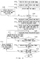
- FIG. 3 is a flowchart showing procedures of a cross-sectional image obtainment process.
- FIG. 3 specific explanations will be given for a cross-sectional image obtainment process performed by the light sheet microscope 100.
- the light sheet microscope 100 first receives specifying of a height range in which cross-sectional images are obtained (step S101).
- the controller 20 receives the specified height range.
- the controller 20 further determines, on the basis of the received height range, the position at which cross-sectional images are obtained, i.e., the position of the light sheet plane in sample S.
- the light sheet microscope 100 irradiates sample S with light sheet LS (step S102), and obtains an image of sample S (step S103).
- the position of the light sheet plane in sample S is not limited particularly. Accordingly, it is possible to irradiate an arbitrary position with light sheet LS so as to obtain an image of sample S, i.e., an image of a light sheet plane by using the image pickup device 12.
- the light sheet microscope 100 makes a focus determination on the basis of the obtained image (step S104).
- whether or not the focal plane of the objective 7 coincides with the light sheet plane is determined by for example the controller 20 on the basis of the contrast of the image. It is also possible to make a determination by a human checking the image visually instead of the controller 20 making the determination so that the controller 20 makes a determination of whether or not the state is a focus state on the basis of the determination state.
- step S104 the light sheet microscope 100 adjusts the relative position between the light sheet plane and the objective 7 in the optical axis directions of the objective 7 (step S105).
- the controller 20 controls the Z drive unit 8 so as to adjust the relative position between the light sheet plane and the objective 7.
- an image of sample S is again obtained (step S103).
- step S104 the processes in step S103 through step S105 are repeated. Note that this focus determination process does not have to be performed on an entire image that has been obtained. It may be performed on part of an image obtained by using an image pickup element of the image pickup device 12.
- the light sheet microscope 100 calculates a focus evaluation value (step S106).
- the controller 20 performs a prescribed computation on the basis of output signals from the photodetector 15 and the photodetector 17 that detected a laser beam scattered on the light sheet plane, and thereby a focus evaluation value is calculated.
- a focus evaluation value is a value that varies in accordance with a degree to which the focal plane of the objective 7 and the light sheet plane coincide.
- a focus evaluation value is calculated from for example (A-B)/(A+B), where A represents an output signal value from the photodetector 15 and B represents an output signal value from the photodetector 17 although this example is not limitative particularly.
- step S107 the light sheet microscope 100 records the value calculated in step S106, as a reference value (step S107).
- a value calculated in step S106 is a focus evaluation value calculated in a focus state. Whether or not the state is a focus state can be determined on the basis of whether or not the focus evaluation value is equal to the value calculated in step S106.
- the value calculated in step S106 is recorded as a reference value so as to use the value in a step that will be described later.
- the light sheet microscope 100 adjusts the relative position between the light sheet plane and sample S in the optical axis directions of the objective 7 so that the light sheet plane moves to the initial position (step S108).
- the controller 20 controls the stage 6 to move the light sheet plane to the initial position, which is one of positions, determined in step S101, at which cross-sectional images are obtained.
- the light sheet microscope 100 calculates a focus evaluation value (step S109), and determines whether or not the focus evaluation value is substantially equal to the reference value recorded in step S107 (step S110).
- This process is performed because there is a possibility that the movement of the stage 6 in step S108 may have moved the focal plane of the objective 7.
- the process in step S110 is similar to that of step S104 in that a focus determination is made.
- the process in step S110 is different in that a focus determination is made on the basis of output signals from the photodetector 15 and the photodetector 17 from that of step S104, in which a focus determination is made on the basis of an image obtained by the image pickup device 12.
- the controller 20 may determine that a focus evaluation value is substantially equal to the reference value when the focus evaluation value is in a prescribed range including the reference value.
- the light sheet microscope 100 adjusts the relative position between the light sheet plane and the objective in the optical axis directions of the objective 7 (step S111).
- the controller 20 controls the Z drive unit 8 so that the focus evaluation value becomes closer to the reference value, and thereby adjusts the relative position between the light sheet plane and the objective 7.
- the light sheet microscope 100 calculates a focus evaluation value again (step S109). Thereafter, until the focus evaluation value is determined to be substantially equal to the reference value, i.e., until the focus evaluation value becomes a value that is in a prescribed range including the reference value (YES in step S110), the processes in step S109 through step S111 are repeated.
- the controller 20 controls the Z drive unit 8 on the basis of an output signal from the photodetector 15 and an output signal from the photodetector 17 in step S109 through step S111.
- the light sheet microscope 100 obtains a cross-sectional image of sample S (step S112). Thereby, a cross-sectional image is obtained with the focal plane of the objective 7 and the light sheet plane coinciding.
- the light sheet microscope 100 determines whether or not the light sheet plane has moved to the final position (step S113).
- the controller 20 determines whether or not the light sheet plane has moved to the final position, which is one of positions, determined in step S101, at which cross-sectional images are obtained.
- the light sheet microscope 100 adjusts the relative position between the light sheet plane and sample S in the optical axis directions of the objective 7 (step S114).
- the controller 20 controls the stage 6 to move the light sheet plane to a different position from among positions, determined in step S101, at which cross-sectional images are obtained.
- the light sheet microscope 100 repeats the processes from step S109 through step S114, and, when it is determined in step S113 that the light sheet plane has moved to the final position, the light sheet microscope 100 terminates the cross-sectional image obtainment process shown in FIG. 3 .
- a focus state is determined on the basis of an output signal from a photodetector that is obtained after changing the relative position between the light sheet plane and sample S. This makes it possible to make the light sheet plane coincide with the focal plane of the objective 7 more swiftly than in a case when a focus state is determined by a human on the basis of an image.
- the calculation amount is smaller even than a case when a focus state is determined by a controller on the basis of an image, making it possible to swiftly make the light sheet plane coincide with the focal plane of the objective 7.
- combinations of two detectors and two pinhole plates make it possible to discriminate between a state in which the focus is on a point closer to the lens than the intended point and a state in which the focus is on a point farther from the lens than the intended point.
- This makes it possible to learn a direction in which a difference has been caused between the focal plane of the objective 7 and the light sheet plane so as to determine the direction in which the relative position between the light sheet plane and the objective is to be adjusted. This point as well contributes to making the light sheet plane coincide with the focal plane of the objective 7 swiftly.
- each time the relative position between the light sheet plane and sample S is changed a focus process is performed on the basis of a signal detected actually at that relative position. This make it possible to make the light sheet plane coincide with the focal plane of the objective 7 more highly accurately than in a case when a focus process is performed on the basis of calibration data.
- the light sheet microscope 100 makes it possible to make the focal plane of an objective coincide with a light sheet plane highly accurately and swiftly.
- the present embodiment has only explained a case when sample S has been moved in the optical axis directions of the objective 7, it is necessary to move the sheet light in the directions of the illumination optical axis to pick up an image when sample S is large.
- the refractive index varies depending upon the position of sample S to shift the focal plane of the objective 7, it is possible to bring the light sheet plane into focus by using the present method even in such a case.
- the controller 20 calculates a focus evaluation value through a software process so as to control the Z drive unit 8 has been shown for the light sheet microscope 100
- a focus process can be performed further faster than a software process.
- a light shielding plate 18 having for example the pinhole array 19 shown in FIG. 4 may be included instead of each of the pinhole plates 14 and 16. Using the light shielding plate 18 makes it possible to detect light from many points in sample S. This can reduce influence caused by an exceptional point (location with a little scattering) in sample S, making it possible to obtain a focus determination result that is more reliable.
- FIG. 5 exemplifies a configuration of a light sheet microscope 200 according to the present embodiment.
- the light sheet microscope 200 is different from the light sheet microscope 100 in that it includes a light sheet illumination optical system 31, a scan mirror 32, a relay optical system 33, a mirror 34 and a scan lens 35 instead of the light sheet illumination optical system 4 and that it includes a stage 6a and a controller 30 instead of the stage 6 and the controller 20, respectively.
- the other points are similar to those of the light sheet microscope 100.
- sample S is irradiated with a light sheet formed by the light sheet illumination optical system 31 via the scan mirror 32, the relay optical system 33, the mirror 34 and the scan lens 35 from a direction that is roughly orthogonal to the optical axis of the objective 7.
- changing the swing angle of the scan mirror 32 moves light sheet LS with which sample S is irradiated, in the optical axis directions of the objective 7.
- the scan mirror 32 is second adjustment means for adjusting the relative position between the light sheet plane and sample S in the optical axis directions of the objective 7.
- the swing angle of the scan mirror 32 is controlled by the controller 30.
- the stage 6a does not have to be an electric stage that can be controlled by the controller 30.
- controller 30 is different from the controller 20 in that it is connected to the scan mirror 32 instead of the stage 6, the hardware of the controller 30 is similar to that of the controller 20. Also, the controller 30 is similar to the controller 20 also in that it is configured to perform the cross-sectional image obtainment process shown in FIG. 3 , in which a plurality of cross-sectional images of sample S are obtained. However, the controller 30 adjusts the relative position between the light sheet plane and the sample S by controlling the scan mirror 32 (step S108 and step S114), which is different from the controller 20.
- the light sheet microscope 200 as well can make the focal plane of the objective coincide with the light sheet plane swiftly and highly accurately, similarly to the light sheet microscope 100. Also, the light sheet microscope 200 makes it possible to change the relative position between the light sheet plane and sample S without moving sample S. This makes it possible to obtain a plurality of cross-sectional images so as to generate a 3-D image without giving stimulation (for example a change in acceleration etc.) caused by movement of sample S.
- FIG. 6 exemplifies a configuration of a light sheet microscope 300 according to the present embodiment.
- the light sheet microscope 300 is different from the light sheet microscope 100 in that a plurality of objectives (objectives 7 and 41) having different magnifications are mounted on a revolver 42, that two light shielding plates (pinhole plates 43 and 45) are provided in such a manner that they can move along the optical path so that the distance from reference positions (positions P2 and P3) varies, that two drive mechanisms (drive mechanisms 44 and 46) that move the two light shielding plates along the optical path are provided and that a controller 40 is provided instead of the controller 20.
- the other points are similar to those of the light sheet microscope 100.
- the drive mechanisms 44 and 46 are third adjustment means for adjusting the positions of the pinhole plates 43 and 45, and movements of the pinhole plates 43 and 45 via the drive mechanisms 44 and 46 are controlled by the controller 40.
- the controller 40 is different from the controller 20 in that it is connected to the drive mechanisms 44 and 46.
- the hardware configuration of the controller 40 is similar to that of the controller 20. Also, the controller 40 performs the cross-sectional image obtainment process shown in FIG. 7 instead of the cross-sectional image obtainment process shown in FIG. 3 .
- FIG. 7 is a flowchart showing procedures of a cross-sectional image obtainment process.
- FIG. 7 specific explanations will be given for a cross-sectional image obtainment process performed by the light sheet microscope 300.
- the light sheet microscope 300 first receives specifying of an objective that is to be used (step S301).
- the controller 40 receives specifying of the objective.
- the light sheet microscope 300 switches to the specified objective (step S302).
- the controller 40 controls the revolver 42 so that the revolver 42 switches the objective arranged in the optical path to the selected objective.
- the light sheet microscope 300 changes, in accordance with the magnification of the switched objective lens, the distances from the reference positions to the two pinhole plates (pinhole plates 43 and 45) (step S303).
- the controller 40 controls the drive mechanisms 44 and 46 in accordance with the magnification of the objective so as to adjust the positions of the two pinhole plates. More specifically, the positions of the two pinhole plates are adjusted in such a manner that the higher the magnification of the objective is, the more the two pinhole plates becomes distant from the reference positions. This is because the position at which the light sheet plane is projected (image position) changes on the basis of a magnitude obtained by multiplying the square of the magnification of the objective by the changing amount of the position of the light sheet plane.
- Step S101 through step S114 that follow are similar to the cross-sectional image obtainment process, shown in FIG. 3 , performed by the light sheet microscope 100.
- the light sheet microscope 300 as well can make the focal plane of the objective coincide with the light sheet plane swiftly and highly accurately, similarly to the light sheet microscope 100. Also, the position of the light shielding plate is adjusted in accordance with the magnification of the objective, making it possible to perform a focus determination stably and without depending on the magnification. Further, by configuring the pinhole diameter in such a manner that the diameter can be varied and setting the optimum pinhole diameter for the objective that is to be inserted into the optical path, it is also possible to perform focusing with higher accuracy.
- FIG. 8 exemplifies a configuration of a light sheet microscope 400 according to the present embodiment.
- the light sheet microscope 400 is different from the light sheet microscope 100 in that it includes an immersion objective 51 instead of the dry objective 7, that the beam splitter 13, the pinhole plate 16 and the photodetector 17 are omitted, that it includes a pinhole plate 52 instead of the pinhole plate 14 and that it includes a controller 50 instead of the controller 20.
- the other points are similar to those of the light sheet microscope 100.
- the pinhole plate 52 is arranged at reference point P2, which corresponds to light-receiving surface S1.
- the controller 50 is different from the controller 20 in that it controls the Z drive unit 8 on the basis of an output signal from the photodetector 15 having detected light that is from the light sheet plane and that passed through the pinhole plate 52.
- the configuration of the controller 50 is similar to that of the controller 20. Also, the controller 50 performs the cross-sectional image obtainment process shown in FIG. 9 instead of the cross-sectional image obtainment process shown in FIG. 3 .
- FIG. 9 is a flowchart showing procedures of a cross-sectional image obtainment process.
- FIG. 9 specific explanations will be given for a cross-sectional image obtainment process performed by the light sheet microscope 400.
- the light sheet microscope 400 first receives specifying of a height range in which cross-sectional images are obtained (step S401). This process is similar to that in step S101 of FIG. 3 .
- the controller 50 determines, on the basis of the received height range, the position at which cross-sectional images are obtained, i.e., the position of the light sheet plane in sample S.
- the light sheet microscope 400 adjusts the relative position between the light sheet plane and sample S in the optical axis directions of the objective 51 so that the light sheet plane moves to the initial position (step S402).
- the controller 50 controls the stage 6 to move the light sheet plane to the initial position, which is one of positions, determined in step S401, at which cross-sectional images are obtained.
- the light sheet microscope 400 irradiates sample S with light sheet LS (step S403). Thereafter, the light sheet microscope 400 adjusts the relative position between the light sheet plane and the objective 51 in the optical axis directions of the objective 51 so that the detected light amount becomes maximum (step S404).
- the controller 50 repeats a process of controlling the Z drive unit 8 in such a manner that output signals from the photodetector 15 increase, and thereby determines the relative position that leads to the maximum detected light amount on the basis of output signals from the photodetector 15.
- the light sheet microscope 400 obtains a cross-sectional image of sample S (step S405). Thereby, a cross-sectional image is obtained with the focal plane of the objective 51 and the light sheet plane coinciding.
- the light sheet microscope 400 determines whether or not the light sheet plane has moved to the final position (step S406).
- the controller 50 determines whether or not the light sheet plane has moved to the final position, which is one of positions, determined in step S401, at which cross-sectional images are obtained.
- the light sheet microscope 400 adjusts the relative position between the light sheet plane and sample S in the optical axis directions of the objective 51 (step S407).
- the controller 50 controls the stage 6 to move the light sheet plane to a different position from among positions, determined in step S401, at which cross-sectional images are obtained.
- the light sheet microscope 400 repeats the processes from step S404 through step S407, and, when it is determined in step S406 that the light sheet plane has moved to the final position, the light sheet microscope 400 terminates the cross-sectional image obtainment process shown in FIG. 9 .
- the light sheet microscope 400 as well can make the focal plane of the objective coincide with the light sheet plane swiftly and highly accurately because a focus state is determined on the basis of an output signal, from an photodetector, that was actually output at each relative position.
- the optical system has a configuration that is simpler than that of the light sheet microscope 100, making it possible to configure the device inexpensively.
- an immersion objective is used as in the present embodiment, an image can be obtained with a high resolution and a there is no air layer between the objective and the sample, leading to a smaller variation of the focal plane caused by a refractive-index difference, and accordingly the movement range of the objective (correction range) is small. This makes it possible to perform focus adjustment at a higher speed.
- a dry objective may be used.
- FIG. 10 exemplifies a configuration of a light sheet microscope 500 according to the present embodiment.
- FIG. 11 exemplifies an array of pixels of an image pickup device 71 included in the light sheet microscope 500.
- the light sheet microscope 500 is different from the light sheet microscope 100 in that it includes an image pickup device 71 instead of the image pickup device 12, that the dichroic mirror 10, the beam splitter 13, the pinhole plate 14, the photodetector 15, the pinhole plate 16 and the photodetector 17 are omitted and that it includes a controller 70 instead of the controller 20.
- the other points are similar to those of the light sheet microscope 100.
- the image pickup device 71 is an image pickup device that includes an image plane phase difference sensor, and is different from the image pickup device 12 in that it includes phase difference evaluation pixels 73 in addition to normal pixels 72 shown in FIG. 11 .
- the phase difference evaluation pixel 73 includes a light shielding member 73b in which a slit 73a is formed.
- the phase difference evaluation pixels 73 include two types having different positions of the slits 73a in relation to the pixel centers, and pixels of the two types are used in pairs.
- the controller 70 is different from the controller 20 in that it controls the Z drive unit 8 on the basis of an output signal from the phase difference evaluation pixel 73.
- the hardware configuration of the controller 70 is similar to that of the controller 20.
- the controller 70 is similar to the controller 20 also in that it is configured to perform the cross-sectional image obtainment process shown in FIG. 3 , in which a plurality of cross-sectional images of sample S are obtained.
- the controller 70 calculates a focus evaluation value and determines focus on the basis of an output signal from the phase difference evaluation pixel 73, differently from the controller 20.
- the light sheet microscope 500 as well can make the focal plane of the objective coincide with the light sheet plane swiftly and highly accurately, similarly to the light sheet microscope 100 because it is possible to discriminate between a state in which the focus is on a point closer to the lens than the intended point and a state in which the focus is on a point farther from the lens than the intended point.
- the optical system has a configuration that is simpler than that of the light sheet microscope 100, making it possible to configure the device inexpensively.
- FIG. 12 exemplifies a configuration of a light sheet microscope 600 according to the present embodiment.
- the light sheet microscope 600 is different from the light sheet microscope 500 in that the emission filter 11 is accommodated in a filter turret 82 so that the emission filter 11 is used by being switched with a glass plate 81 and that a controller 80 is included instead of the controller 70.
- the other points are similar to those of the light sheet microscope 500.
- the filter turret 82 is a device that switches the optical element arranged in the optical path between the emission filter 11 and the glass plate 81, and the switching operation is controlled by the controller 80.
- the glass plate 81 is a flat plate that transmits fluorescence and a laser beam, and the glass plate 81 has a thickness that results in a situation where the optical path length in that glass plate 81 is roughly equal to the optical path length in the emission filter 11.
- the controller 80 is different from the controller 70 in that it is connected the filter turret 82, but the hardware configuration of the controller 80 is similar to that of the controller 70. Also, the controller 80 performs the cross-sectional image obtainment process shown in FIG. 13 instead of the cross-sectional image obtainment process shown in FIG. 3 .
- FIG. 13 is a flowchart showing procedures of a cross-sectional image obtainment process.
- FIG. 13 specific explanations will be given for a cross-sectional image obtainment process performed by the light sheet microscope 600.
- the light sheet microscope 600 first removes the emission filter 11 from the optical path (step S701).
- the controller 80 controls the rotation of the filter turret 82 so as to remove the emission filter 11 from the optical path and instead inserts the glass plate 81 into the optical path.
- step S101 through step S111 are similar to those of the cross-sectional image obtainment process shown in FIG. 3 and performed by the light sheet microscope 100.
- the light sheet microscope 600 inserts the emission filter 11 into the optical path (step S702).
- the controller 80 controls the rotation of the filter turret 82 so as to remove the glass plate 81 from the optical path and instead inserts the emission filter 11 into the optical path.
- the light sheet microscope 600 obtains a cross-sectional image of sample S (step S112), and further determines whether or not the light sheet plane has moved to the final position (step S113).
- the light sheet microscope 600 When determining that the light sheet plane has not moved to the final position, the light sheet microscope 600 removes the emission filter 11 from the optical path (step S703), and thereafter adjusts the relative position between the light sheet plane and sample S in the optical axis direction of the objective 7 (step S114). Note that the process in step S703 is similar to that is step S701. Lastly, the light sheet microscope 600 repeats the processes from step S109 through step S114, and when it is determined in step S113 that the light sheet plane has moved to the final position, the light sheet microscope 600 terminates the cross-sectional image obtainment process shown in FIG. 13 .
- the light sheet microscope 600 as well can make the focal plane of the objective coincide with the light sheet plane swiftly and highly accurately, similarly to the light sheet microscope 100.
- the optical system has a configuration that is simpler than that of the light sheet microscope 100, making it possible to configure the device inexpensively similarly to the light sheet microscope 500.
- a focus determination process is performed with a laser beam entering the image pickup device 71. This makes it possible to perform a focus determination more stably than the light sheet microscope 500, in which a focus determination process is performed with only fluorescence, which is weaker than laser beams and is generated in different amounts depending upon the positions etc. in sample S, entering the image pickup device 71.
- the emission filter 11 and the glass plate 81 are switched by the filter turret 82.
- a plurality of emission filters of different specifications may be accommodated in the filter turret 82, and emission filters may be switched depending upon the fluorescence wavelengths by using the filter turret 82.
- a focus determination may be conducted with a bandpass filter, which transmits only a laser beam, inserted into the optical path instead of the glass plate 81.
- FIG. 14 exemplifies a configuration of a light sheet microscope 700 according to the present embodiment.
- the light sheet microscope 700 is different from the light sheet microscope 500 in that it includes the image pickup device 12 instead of the image pickup device 71, that it includes the dichroic mirror 10 and a phase difference auto focus (which will be referred to as "AF" hereinafter) sensor 91 and that it includes a controller 90 instead of the controller 70.
- the other points are similar to those of the light sheet microscope 500.
- the phase difference AF sensor 91 is a sensor unit that includes a separator lens 92 and a sensor 93 and that performs a phase difference AF process, and is provided on the optical path branching from the optical path between the photodetector 12 and the objective 7.
- the phase difference AF sensor 91 functions substantially similarly to the image plane phase difference sensor provided in the image pickup device 71 of the light sheet microscope 500.
- the controller 90 is different from the controller 70 in that it is connected to the phase difference AF sensor 91 and that it controls the Z drive unit 8 on the basis of an output signal from the phase difference AF sensor 91.
- the hardware configuration of the controller 90 is similar to that of the controller 70.
- the controller 90 is similar to the controller 70 also in that it is configured to perform the cross-sectional image obtainment process shown in FIG. 2 .
- the controller 90 calculates a focus evaluation value and determines focus on the basis of an output signal from the phase difference AF sensor 91, differently from the controller 70.
- the light sheet microscope 700 as well can make the focal plane of the objective coincide with the light sheet plane swiftly and highly accurately, similarly to the light sheet microscope 500. It is also possible to consider inserting a convex lens into a space between the dichroic mirror 10 and the phase difference AF sensor 91 so as to increase NA of a light beam that enters the phase difference AF sensor 91, and thereby to increase the accuracy of a focus determination.
- FIG. 15 exemplifies a configuration of a light sheet microscope 800 according to the present embodiment.
- the light sheet microscope 800 is different from the light sheet microscope 100 in that it includes a mirror 94 instead of the dichroic mirror 10.
- the other points are similar to the light sheet microscope 100.
- the mirror 94 is arranged at a position out of the optical axis of the objective 7 that is in the optical path between the objective 7 and the image pickup device 12. In more detail, the mirror 94 is arranged at a position at which the mirror 94 does not block a light flux that is to be detected by the image pickup device 12. Note that 2/3-inch CCD cameras, which are often used for microscopes, usually utilize only about half of the field of view that microscopes inherently have.
- the light sheet microscope 800 as well can make the focal plane of the objective coincide with the light sheet plane swiftly and highly accurately, similarly to the light sheet microscope 100. Also, a cross-sectional image can be obtained not via the dichroic mirror 10, making it possible to obtain a cross-sectional image that is brighter than one obtained by the light sheet microscope 100.
- the controller may perform a continuous AF process that continuously controls the Z drive unit so that the light sheet plane and the focal plane become closer on the basis of light from the light sheet plane detected via the objective.
- the controller may control the Z drive unit in each relative position between the sheet plane and the sample or may control the Z drive unit on the basis of light from the light sheet plane when the relative position between the sheet plane and the sample is at a prescribed position.
Abstract
Description
- The disclosure of the present invention is related to a light sheet microscope and a control method for a light sheet microscope.
- In the field of fluorescence microscopes, a technique is known in which a sample is irradiated with a laser beam from a direction that is orthogonal to the optical axis of the objective so as to form, in the sample, a light sheet orthogonal to the optical axis of the objective. A light sheet microscope using this technique is disclosed in for example
U.S. Unexamined Patent Application Publication No 2015/0286042 and International Publication Pamphlet No.WO2015/184124 . Light sheet microscopes can generate an excellent 3-D image of a sample at a high speed with suppressed fading of fluorescence, which is a great advantage. - In recent years, purposes of this technique are not limited to the obtainment of a 3-D image of a creature such as zebrafish that is labeled with fluorescent protein as a target molecule. This technique draws attention also as a technique aiming to be applied to so-called "drug-discovery screening", in which medical effects are evaluated by obtaining a 3-D image of a 3-D cultured cell such as spheroid or organoid and using an image analysis technique. This technique is expected to be applied to a wide range of applications.
- In order to obtain a 3-D image of a sample, a light sheet microscope usually obtains a plurality of cross-sectional images while relatively moving the light sheet and the sample along the observation optical axis (optical axis of the objective). In many cases, the light sheet and the objective are fixed after the light sheet is set to be formed on the focal plane of the objective. Then, a plurality of cross-sectional images are obtained by sequentially moving the sample in the optical axis direction.
- However, a change of an observed location of the sample (i.e., a plane on which the light sheet is formed in the sample, which will be referred to as a light sheet plane) in this method changes a component ratio of media between the objective and the light sheet plane (e.g., the ratio between the air, the culture solution and the inside of the sample). Thereby, the optical path length between the objective and the light sheet plane changes. This results in a situation where even when the objective is not moved, the focal plane of the objective moves in the optical axis directions and the focal plane of the objective does not coincide with the light sheet plane. Also, the refractive-index distribution in the sample also changes the movement amount of the focal plane. Also, the more the optical resolution of a 3-D image is to be increased, i.e., the more the numerical aperture of the objective is to be increased by reducing the thickness of the light sheet, the greater the influence caused by this difference becomes because the shallower the focal depth is.
-
U.S. Unexamined Patent Application Publication No 2015/0286042 and International Publication Pamphlet No.WO 2015/184124 above disclose a technique that performs calibration by using the observation target before observation so as to generate data for correcting a difference of the focal plane of the objective. Using this technique can suppress a difference between the focal plane of the objective and the light sheet plane to some extent. - However, when the refractive index of a sample has a steep change inside or other cases, it is difficult to suppress differences with sufficient accuracy. By obtaining more images in calibration, it is possible to improve the correction accuracy. However, obtaining more images takes a longer time for calibration. Also, there is a risk that calibration may damage the sample.
- In view of the above situation, it is an object of an aspect of the present invention to provide a light sheet microscope and a control method for light sheet microscope that make it possible to make the focal plane of the objective coincide with the light sheet plane swiftly and highly accurately.
- A light sheet microscope according to an aspect of the present invention includes an objective, an illumination optical system that irradiates sample with a light sheet from a direction that is different from an optical axis direction of the objective, first adjustment means for adjusting a relative position between a light sheet plane on which the light sheet is formed and the objective in the optical axis direction of the objective, second adjustment means for adjusting a relative position between the light sheet plane and the sample in the optical axis direction of the objective, and a controller that controls the first adjustment means on the basis of light that is from the light sheet plane and that is detected via the objective when a relative position between the light sheet plane and the sample is changed by the second adjustment means.
- A control method for a light sheet microscope having an objective according to another aspect of the present invention includes irradiating sample with a light sheet from a direction that is different from an optical axis direction of the objective, adjusting a relative position between a light sheet plane on which the light sheet is formed and the sample in the optical axis direction of the objective, adjusting a relative position between the light sheet plane and the objective in the optical axis direction of the objective on the basis of light that is from the light sheet plane and that is detected via the objective when a relative position between the light sheet plane and the sample is adjusted, and obtaining an image of the sample that is irradiated with the light sheet.
- An aspect of the present invention can provide a light sheet microscope and a control method for a light sheet microscope that can make the focal plane of an objective coincide with a light sheet plane swiftly and highly accurately.
- The present invention will be more apparent from the following detailed description when the accompanying drawings are referenced.
-
FIG. 1 exemplifies a configuration of alight sheet microscope 100 according to the first embodiment; -
FIG. 2 exemplifies a configuration of hardware of acontroller 20; -
FIG. 3 is a flowchart showing procedures of a cross-sectional image obtainment process according to the first embodiment; -
FIG. 4 exemplifies a configuration of alight shielding plate 18 including apinhole array 19; -
FIG. 5 exemplifies a configuration of alight sheet microscope 200 according to the second embodiment; -
FIG. 6 exemplifies a configuration of alight sheet microscope 300 according to the third embodiment; -
FIG. 7 is a flowchart showing procedures of a cross-sectional image obtainment process according to the third embodiment; -
FIG. 8 exemplifies a configuration of alight sheet microscope 400 according to the fourth embodiment; -
FIG. 9 is a flowchart showing procedures of a cross-sectional image obtainment process according to the fourth embodiment; -
FIG. 10 exemplifies a configuration of alight sheet microscope 500 according to the fifth embodiment; -
FIG. 11 exemplifies an array of pixels of animage pickup device 71; -
FIG. 12 exemplifies a configuration of alight sheet microscope 600 according to the sixth embodiment; -
FIG. 13 is a flowchart showing procedures of a cross-sectional image obtainment process according to the sixth embodiment; -
FIG. 14 exemplifies a configuration of alight sheet microscope 700 according to the seventh embodiment; and -
FIG. 15 exemplifies a configuration of alight sheet microscope 800 according to the eighth embodiment. -
FIG. 1 exemplifies a configuration of alight sheet microscope 100 according to the present embodiment. Thelight sheet microscope 100 is a apparatus that obtains a cross-sectional image of sample S immersed in medium M such as culture solution, transparentization solution, etc. Sample S is for example a biological cell that was labeled by fluorochrome. Sample S is contained in for example asample container 5 such as a cuvette etc. mounted on astage 6. - The
light sheet microscope 100 includes alaser 1, anoptical fiber 2, a light sheet illuminationoptical system 4, thestage 6, adry objective 7,Z drive unit 8, atube lens 9, adichroic mirror 10, anemission filter 11 and animage pickup device 12. - The light sheet illumination
optical system 4 includes for example a collector lens and a cylindrical lens, and irradiates sample S with a light sheet from a direction different from the optical axis direction of theobjective 7. More specifically, the light sheet illuminationoptical system 4 is arranged so that the emission optical axis of the light sheet illuminationoptical system 4 is roughly orthogonal to the optical axis of theobjective 7. The light sheet illuminationoptical system 4 is configured to irradiate sample S with light sheet LS from a direction that is roughly orthogonal to the optical axis of theobjective 7. In this example, a light sheet is illumination light that forms a sheet-shaped illumination area. Light sheet LS has a sheet-like shape that is thin in the optical axis directions of the objective 7 in sample S. Also, "roughly orthogonal" refers to a range that may be considered by those skilled in the art as an error in setting or manufacturing from the orthogonal state. - The
stage 6 is an electric stage that moves in the optical axis directions of theobjective 7. Thestage 6 is second adjustment means for adjusting the relative position (i.e. relative distance) between a light sheet plane and sample S in the optical axis directions of theobjective 7. The movement of thestage 6 is controlled by acontroller 20, which will be explained later. - The
Z drive unit 8 is an electric unit that moves the objective 7 in the optical axis directions of theobjective 7. TheZ drive unit 8 is first adjustment means for adjusting the relative position (i.e. relative distance) between a light sheet plane on which light sheet LS is formed and the objective 7 in the optical axis directions of theobjective 7. Movements of theobjective 7 via theZ drive unit 8 are controlled by thecontroller 20, which will be described later. - The
dichroic mirror 10 reflects a laser beam so as to split the beam into a laser beam and fluorescence. Theemission filter 11 shields a laser beam and transmits fluorescence. Thedichroic mirror 10 and theemission filter 11 limit the entrance of a laser beam to theimage pickup device 12. - The
image pickup device 12 obtains, via theobjective 7, an image of sample S that is irradiated with light sheet LS. Theimage pickup device 12 is for example a digital camera having a 2-D image sensor such as a CCD (Charge Coupled Device, a CMOS (Complementary Metal Oxide Semiconductor), etc. Theimage pickup device 12 has light-receiving surface S1, and is arranged in such a manner that the front-side focal position of theobjective 7 is projected on the light-receiving surface S1. Position P1 on light-receiving surface S1 shown inFIG. 1 is the position at which the front-side focal position of theobjective 7 is projected, i.e., the position that is optically conjugate with the front-side focal position of theobjective 7. - The
light sheet microscope 100 further includes abeam splitter 13, two light shielding plates (pinhole plates 14 and 16) and two photodetectors (photodetectors 15 and 17) in the reflection optical path of the dichroic mirror 10 (the optical path branching, by thedichroic mirror 10, from the optical path between theimage pickup device 12 and the objective 7). - The
beam splitter 13 splits the laser beam reflected by thedichroic mirror 10 at a ratio of 50: 50. Thepinhole plate 14 and thephotodetector 15 are arranged in one of the optical paths branched by thebeam splitter 13. Thepinhole plate 16 and thephotodetector 17 are arranged on the other of the optical paths branched by thebeam splitter 13. - The
pinhole plate 14 is a first light shielding plate having an opening, and is arranged on the far side of position P2 at which the front-side focal position of theobjective 7 is projected. Thepinhole plate 16 is a second light shielding plate having an opening, and is arranged on the near side of position P3 at which the front-side focal position of theobjective 7 is projected. Positions P2 and P3 are positions that are optically conjugate with the front-side focal position of theobjective 7, and are, in other words, positions corresponding to the light-receiving surface S1 (position P1) of theimage pickup device 12. Hereinafter, positions P2 and P3 may respectively be referred to also as reference positions, as necessary. In this example, "near side" means a near side with respect to the traveling direction of the light, and "far side" means a far side with respect to the traveling direction of the light. - The
photodetector 15 is a first photodetector that detects light that is from the light sheet plane and that passed through thepinhole plate 14, and detects a laser beam in a dedicated manner. Thephotodetector 17 is a second photodetector that detects light that is from the light sheet plane and that passed through thepinhole plate 16, and detects a laser beam in a dedicated manner. Thephotodetector 15 and thephotodetector 17 are for example Photomultiplier Tubes (PMTs), and output a signal in accordance with a detected light amount. - The
light sheet microscope 100 further includes thecontroller 20. Thecontroller 20 is configured to perform a cross-sectional image obtainment process for obtaining a plurality of cross-sectional images of sample S. The outline of the cross-sectional image obtainment process is as below, although this process will be described later in detail. - In the cross-sectional image obtainment process, the
controller 20 varies the relative position between the light sheet plane and the sample S by controlling thestage 6 in order to obtain a plurality of cross-sectional images by irradiating different positions of sample S with a light sheet. Then, the refractive-index distribution in the medium between the light sheet plane and the objective 7 (including the air, medium M and the inside of sample S) varies. This moves the focal plane of theobjective 7 in the optical axis directions even when the objective is not moved. Because of this, just controlling thestage 6 results in a difference between a light sheet plane and the focal plane of the objective. Thus, after controlling thestage 6, thecontroller 20 further controls theZ drive unit 8 on the basis of the light that is from the light sheet plane and that is detected via theobjective 7, and adjusts the relative position between the light sheet plane and theobjective 7. More specifically, theZ drive unit 8 is controlled so that the focal plane of theobjective 7 is made closer to the light sheet plane and thereby these positions coincide. Thereby, it is possible to obtain a plurality of cross-sectional images with the focal plane of theobjective 7 and the light sheet plane coinciding highly accurately. -
FIG. 2 exemplifies a configuration of hardware of thecontroller 20. Thecontroller 20 is for example a standard computer, and includes aprocessor 21, amemory 22, an input/output interface 23, astorage 24 and a portable recordingmedium drive device 25 into which aportable recording medium 26 is inserted. They are connected to each other via abus 27. Note thatFIG. 2 shows an example of the hardware configuration of thecontroller 20, and thecontroller 20 is not limited to this configuration. - The
processor 21 is for example a CPU (Central Processing Unit), an MPU (Micro Processing Unit) a DSP (Digital Signal Processor), etc. Theprocessor 21 executes a program so as to perform the programmed process such as the cross-sectional image obtainment process described above. Thememory 22 is for example a RAM (Random Access Memory). When a program is to be executed, thememory 22 temporarily stores the program or data that are recorded in thestorage 24 or theportable recording medium 26. - The input/
output interface 23 is a circuit that exchanges a signal with devices other than the controller 20 (for example thestage 6, theZ drive unit 8, thephotodetector 15, thephotodetector 17, etc.). Thestorage 24 is for example a hard disk, a flash memory, and is used mainly for recording various types of data and programs. The portable recordingmedium drive device 25 accommodates theportable recording medium 26 such as an optical disk, a CompactFlash (registered trademark), etc. Theportable recording medium 26 plays a role of assisting thestorage 24. -
FIG. 3 is a flowchart showing procedures of a cross-sectional image obtainment process. Hereinafter, while referring toFIG. 3 , specific explanations will be given for a cross-sectional image obtainment process performed by thelight sheet microscope 100. - The
light sheet microscope 100 first receives specifying of a height range in which cross-sectional images are obtained (step S101). In this example, when the user uses an input device (not shown) so as to input a height range in which cross-sectional images are obtained, thecontroller 20 receives the specified height range. Thecontroller 20 further determines, on the basis of the received height range, the position at which cross-sectional images are obtained, i.e., the position of the light sheet plane in sample S. - Next, the
light sheet microscope 100 irradiates sample S with light sheet LS (step S102), and obtains an image of sample S (step S103). In this example, the position of the light sheet plane in sample S is not limited particularly. Accordingly, it is possible to irradiate an arbitrary position with light sheet LS so as to obtain an image of sample S, i.e., an image of a light sheet plane by using theimage pickup device 12. - Thereafter, the
light sheet microscope 100 makes a focus determination on the basis of the obtained image (step S104). In the determination, whether or not the focal plane of theobjective 7 coincides with the light sheet plane is determined by for example thecontroller 20 on the basis of the contrast of the image. It is also possible to make a determination by a human checking the image visually instead of thecontroller 20 making the determination so that thecontroller 20 makes a determination of whether or not the state is a focus state on the basis of the determination state. - When the state is determined to be not a focus state (NO in step S104), the
light sheet microscope 100 adjusts the relative position between the light sheet plane and theobjective 7 in the optical axis directions of the objective 7 (step S105). In this example, thecontroller 20 controls theZ drive unit 8 so as to adjust the relative position between the light sheet plane and theobjective 7. Thereafter, an image of sample S is again obtained (step S103). Thereafter, until the state is determined to be a focus state (YES in step S104), the processes in step S103 through step S105 are repeated. Note that this focus determination process does not have to be performed on an entire image that has been obtained. It may be performed on part of an image obtained by using an image pickup element of theimage pickup device 12. - When the state is determined to be a focus state, the
light sheet microscope 100 calculates a focus evaluation value (step S106). In this example, thecontroller 20 performs a prescribed computation on the basis of output signals from thephotodetector 15 and thephotodetector 17 that detected a laser beam scattered on the light sheet plane, and thereby a focus evaluation value is calculated. A focus evaluation value is a value that varies in accordance with a degree to which the focal plane of theobjective 7 and the light sheet plane coincide. A focus evaluation value is calculated from for example (A-B)/(A+B), where A represents an output signal value from thephotodetector 15 and B represents an output signal value from thephotodetector 17 although this example is not limitative particularly. - Thereafter, the
light sheet microscope 100 records the value calculated in step S106, as a reference value (step S107). A value calculated in step S106 is a focus evaluation value calculated in a focus state. Whether or not the state is a focus state can be determined on the basis of whether or not the focus evaluation value is equal to the value calculated in step S106. Thus, in step S107, the value calculated in step S106 is recorded as a reference value so as to use the value in a step that will be described later. - Next, the
light sheet microscope 100 adjusts the relative position between the light sheet plane and sample S in the optical axis directions of theobjective 7 so that the light sheet plane moves to the initial position (step S108). In this example, thecontroller 20 controls thestage 6 to move the light sheet plane to the initial position, which is one of positions, determined in step S101, at which cross-sectional images are obtained. - Thereafter, the
light sheet microscope 100 calculates a focus evaluation value (step S109), and determines whether or not the focus evaluation value is substantially equal to the reference value recorded in step S107 (step S110). This process is performed because there is a possibility that the movement of thestage 6 in step S108 may have moved the focal plane of theobjective 7. Note that the process in step S110 is similar to that of step S104 in that a focus determination is made. However, the process in step S110 is different in that a focus determination is made on the basis of output signals from thephotodetector 15 and thephotodetector 17 from that of step S104, in which a focus determination is made on the basis of an image obtained by theimage pickup device 12. Also, thecontroller 20 may determine that a focus evaluation value is substantially equal to the reference value when the focus evaluation value is in a prescribed range including the reference value. - When a focus evaluation value is determined to be not equal to the reference value in step S110 (NO in step S110), the
light sheet microscope 100 adjusts the relative position between the light sheet plane and the objective in the optical axis directions of the objective 7 (step S111). In this example, thecontroller 20 controls theZ drive unit 8 so that the focus evaluation value becomes closer to the reference value, and thereby adjusts the relative position between the light sheet plane and theobjective 7. - The
light sheet microscope 100 calculates a focus evaluation value again (step S109). Thereafter, until the focus evaluation value is determined to be substantially equal to the reference value, i.e., until the focus evaluation value becomes a value that is in a prescribed range including the reference value (YES in step S110), the processes in step S109 through step S111 are repeated. In other words, thecontroller 20 controls theZ drive unit 8 on the basis of an output signal from thephotodetector 15 and an output signal from thephotodetector 17 in step S109 through step S111. - When the focus evaluation value is determined to be substantially equal to the reference value (YES in step S110), the
light sheet microscope 100 obtains a cross-sectional image of sample S (step S112). Thereby, a cross-sectional image is obtained with the focal plane of theobjective 7 and the light sheet plane coinciding. - Thereafter, the
light sheet microscope 100 determines whether or not the light sheet plane has moved to the final position (step S113). In this example, thecontroller 20 determines whether or not the light sheet plane has moved to the final position, which is one of positions, determined in step S101, at which cross-sectional images are obtained. - When determining that the light sheet plane has not moved to the final position, the
light sheet microscope 100 adjusts the relative position between the light sheet plane and sample S in the optical axis directions of the objective 7 (step S114). In this example, thecontroller 20 controls thestage 6 to move the light sheet plane to a different position from among positions, determined in step S101, at which cross-sectional images are obtained. Thereafter, thelight sheet microscope 100 repeats the processes from step S109 through step S114, and, when it is determined in step S113 that the light sheet plane has moved to the final position, thelight sheet microscope 100 terminates the cross-sectional image obtainment process shown inFIG. 3 . - In the
light sheet microscope 100, a focus state is determined on the basis of an output signal from a photodetector that is obtained after changing the relative position between the light sheet plane and sample S. This makes it possible to make the light sheet plane coincide with the focal plane of theobjective 7 more swiftly than in a case when a focus state is determined by a human on the basis of an image. The calculation amount is smaller even than a case when a focus state is determined by a controller on the basis of an image, making it possible to swiftly make the light sheet plane coincide with the focal plane of theobjective 7. - Also, in the
light sheet microscope 100, combinations of two detectors and two pinhole plates make it possible to discriminate between a state in which the focus is on a point closer to the lens than the intended point and a state in which the focus is on a point farther from the lens than the intended point. This makes it possible to learn a direction in which a difference has been caused between the focal plane of theobjective 7 and the light sheet plane so as to determine the direction in which the relative position between the light sheet plane and the objective is to be adjusted. This point as well contributes to making the light sheet plane coincide with the focal plane of theobjective 7 swiftly. - Further, in the
light sheet microscope 100, each time the relative position between the light sheet plane and sample S is changed, a focus process is performed on the basis of a signal detected actually at that relative position. This make it possible to make the light sheet plane coincide with the focal plane of theobjective 7 more highly accurately than in a case when a focus process is performed on the basis of calibration data. - As described above, the
light sheet microscope 100 makes it possible to make the focal plane of an objective coincide with a light sheet plane highly accurately and swiftly. Note that while the present embodiment has only explained a case when sample S has been moved in the optical axis directions of theobjective 7, it is necessary to move the sheet light in the directions of the illumination optical axis to pick up an image when sample S is large. In the above situation, while there is a possibility that the refractive index varies depending upon the position of sample S to shift the focal plane of theobjective 7, it is possible to bring the light sheet plane into focus by using the present method even in such a case. Also, while an example where thecontroller 20 calculates a focus evaluation value through a software process so as to control theZ drive unit 8 has been shown for thelight sheet microscope 100, it is also possible to evaluate a focus evaluation value by using for example a circuit such as a comparator etc. instead of thecontroller 20 so as to output a control signal in accordance with the evaluation result to theZ drive unit 8. In such a case, a focus process can be performed further faster than a software process. Also, while an example where thepinhole plates light sheet microscope 100, alight shielding plate 18 having for example thepinhole array 19 shown inFIG. 4 may be included instead of each of thepinhole plates light shielding plate 18 makes it possible to detect light from many points in sample S. This can reduce influence caused by an exceptional point (location with a little scattering) in sample S, making it possible to obtain a focus determination result that is more reliable. -
FIG. 5 exemplifies a configuration of alight sheet microscope 200 according to the present embodiment. Thelight sheet microscope 200 is different from thelight sheet microscope 100 in that it includes a light sheet illuminationoptical system 31, ascan mirror 32, a relayoptical system 33, amirror 34 and ascan lens 35 instead of the light sheet illuminationoptical system 4 and that it includes astage 6a and acontroller 30 instead of thestage 6 and thecontroller 20, respectively. The other points are similar to those of thelight sheet microscope 100. - In the
light sheet microscope 200, sample S is irradiated with a light sheet formed by the light sheet illuminationoptical system 31 via thescan mirror 32, the relayoptical system 33, themirror 34 and thescan lens 35 from a direction that is roughly orthogonal to the optical axis of theobjective 7. Also, changing the swing angle of thescan mirror 32 moves light sheet LS with which sample S is irradiated, in the optical axis directions of theobjective 7. Accordingly, in thelight sheet microscope 200, thescan mirror 32 is second adjustment means for adjusting the relative position between the light sheet plane and sample S in the optical axis directions of theobjective 7. The swing angle of thescan mirror 32 is controlled by thecontroller 30. Thus, thestage 6a does not have to be an electric stage that can be controlled by thecontroller 30. - While the
controller 30 is different from thecontroller 20 in that it is connected to thescan mirror 32 instead of thestage 6, the hardware of thecontroller 30 is similar to that of thecontroller 20. Also, thecontroller 30 is similar to thecontroller 20 also in that it is configured to perform the cross-sectional image obtainment process shown inFIG. 3 , in which a plurality of cross-sectional images of sample S are obtained. However, thecontroller 30 adjusts the relative position between the light sheet plane and the sample S by controlling the scan mirror 32 (step S108 and step S114), which is different from thecontroller 20. - The
light sheet microscope 200 as well can make the focal plane of the objective coincide with the light sheet plane swiftly and highly accurately, similarly to thelight sheet microscope 100. Also, thelight sheet microscope 200 makes it possible to change the relative position between the light sheet plane and sample S without moving sample S. This makes it possible to obtain a plurality of cross-sectional images so as to generate a 3-D image without giving stimulation (for example a change in acceleration etc.) caused by movement of sample S. -
FIG. 6 exemplifies a configuration of alight sheet microscope 300 according to the present embodiment. Thelight sheet microscope 300 is different from thelight sheet microscope 100 in that a plurality of objectives (objectives 7 and 41) having different magnifications are mounted on arevolver 42, that two light shielding plates (pinhole plates 43 and 45) are provided in such a manner that they can move along the optical path so that the distance from reference positions (positions P2 and P3) varies, that two drive mechanisms (drivemechanisms 44 and 46) that move the two light shielding plates along the optical path are provided and that acontroller 40 is provided instead of thecontroller 20. The other points are similar to those of thelight sheet microscope 100. - The
drive mechanisms pinhole plates pinhole plates drive mechanisms controller 40. - The
controller 40 is different from thecontroller 20 in that it is connected to thedrive mechanisms controller 40 is similar to that of thecontroller 20. Also, thecontroller 40 performs the cross-sectional image obtainment process shown inFIG. 7 instead of the cross-sectional image obtainment process shown inFIG. 3 . -
FIG. 7 is a flowchart showing procedures of a cross-sectional image obtainment process. Hereinafter, while referring toFIG. 7 , specific explanations will be given for a cross-sectional image obtainment process performed by thelight sheet microscope 300. - The
light sheet microscope 300 first receives specifying of an objective that is to be used (step S301). In this example, when the user selects an objective by using an input device (not shown), thecontroller 40 receives specifying of the objective. - Thereafter, the
light sheet microscope 300 switches to the specified objective (step S302). In this example, thecontroller 40 controls therevolver 42 so that therevolver 42 switches the objective arranged in the optical path to the selected objective. - When the objectives have been switched, the
light sheet microscope 300 changes, in accordance with the magnification of the switched objective lens, the distances from the reference positions to the two pinhole plates (pinhole plates 43 and 45) (step S303). In this example, thecontroller 40 controls thedrive mechanisms - Step S101 through step S114 that follow are similar to the cross-sectional image obtainment process, shown in
FIG. 3 , performed by thelight sheet microscope 100. - The
light sheet microscope 300 as well can make the focal plane of the objective coincide with the light sheet plane swiftly and highly accurately, similarly to thelight sheet microscope 100. Also, the position of the light shielding plate is adjusted in accordance with the magnification of the objective, making it possible to perform a focus determination stably and without depending on the magnification. Further, by configuring the pinhole diameter in such a manner that the diameter can be varied and setting the optimum pinhole diameter for the objective that is to be inserted into the optical path, it is also possible to perform focusing with higher accuracy. -
FIG. 8 exemplifies a configuration of alight sheet microscope 400 according to the present embodiment. Thelight sheet microscope 400 is different from thelight sheet microscope 100 in that it includes animmersion objective 51 instead of thedry objective 7, that thebeam splitter 13, thepinhole plate 16 and thephotodetector 17 are omitted, that it includes apinhole plate 52 instead of thepinhole plate 14 and that it includes acontroller 50 instead of thecontroller 20. The other points are similar to those of thelight sheet microscope 100. - The
pinhole plate 52 is arranged at reference point P2, which corresponds to light-receiving surface S1. Thecontroller 50 is different from thecontroller 20 in that it controls theZ drive unit 8 on the basis of an output signal from thephotodetector 15 having detected light that is from the light sheet plane and that passed through thepinhole plate 52. The configuration of thecontroller 50 is similar to that of thecontroller 20. Also, thecontroller 50 performs the cross-sectional image obtainment process shown inFIG. 9 instead of the cross-sectional image obtainment process shown inFIG. 3 . -
FIG. 9 is a flowchart showing procedures of a cross-sectional image obtainment process. Hereinafter, while referring toFIG. 9 , specific explanations will be given for a cross-sectional image obtainment process performed by thelight sheet microscope 400. - The
light sheet microscope 400 first receives specifying of a height range in which cross-sectional images are obtained (step S401). This process is similar to that in step S101 ofFIG. 3 . In this example, thecontroller 50 determines, on the basis of the received height range, the position at which cross-sectional images are obtained, i.e., the position of the light sheet plane in sample S. - Next, the
light sheet microscope 400 adjusts the relative position between the light sheet plane and sample S in the optical axis directions of the objective 51 so that the light sheet plane moves to the initial position (step S402). In this example, thecontroller 50 controls thestage 6 to move the light sheet plane to the initial position, which is one of positions, determined in step S401, at which cross-sectional images are obtained. - Further, the
light sheet microscope 400 irradiates sample S with light sheet LS (step S403). Thereafter, thelight sheet microscope 400 adjusts the relative position between the light sheet plane and the objective 51 in the optical axis directions of the objective 51 so that the detected light amount becomes maximum (step S404). In this example, thecontroller 50 repeats a process of controlling theZ drive unit 8 in such a manner that output signals from thephotodetector 15 increase, and thereby determines the relative position that leads to the maximum detected light amount on the basis of output signals from thephotodetector 15. - When the adjustment between the light sheet plane and the objective 51 is terminated, the
light sheet microscope 400 obtains a cross-sectional image of sample S (step S405). Thereby, a cross-sectional image is obtained with the focal plane of the objective 51 and the light sheet plane coinciding. - Thereafter, the
light sheet microscope 400 determines whether or not the light sheet plane has moved to the final position (step S406). In this example, thecontroller 50 determines whether or not the light sheet plane has moved to the final position, which is one of positions, determined in step S401, at which cross-sectional images are obtained. - When determining that the light sheet plane has not moved to the final position, the
light sheet microscope 400 adjusts the relative position between the light sheet plane and sample S in the optical axis directions of the objective 51 (step S407). In this example, thecontroller 50 controls thestage 6 to move the light sheet plane to a different position from among positions, determined in step S401, at which cross-sectional images are obtained. Thereafter, thelight sheet microscope 400 repeats the processes from step S404 through step S407, and, when it is determined in step S406 that the light sheet plane has moved to the final position, thelight sheet microscope 400 terminates the cross-sectional image obtainment process shown inFIG. 9 . - The
light sheet microscope 400 as well can make the focal plane of the objective coincide with the light sheet plane swiftly and highly accurately because a focus state is determined on the basis of an output signal, from an photodetector, that was actually output at each relative position. Also, the optical system has a configuration that is simpler than that of thelight sheet microscope 100, making it possible to configure the device inexpensively. Further, when an immersion objective is used as in the present embodiment, an image can be obtained with a high resolution and a there is no air layer between the objective and the sample, leading to a smaller variation of the focal plane caused by a refractive-index difference, and accordingly the movement range of the objective (correction range) is small. This makes it possible to perform focus adjustment at a higher speed. Note that while the above embodiment uses an immersion objective, a dry objective may be used. -
FIG. 10 exemplifies a configuration of alight sheet microscope 500 according to the present embodiment.FIG. 11 exemplifies an array of pixels of animage pickup device 71 included in thelight sheet microscope 500. Thelight sheet microscope 500 is different from thelight sheet microscope 100 in that it includes animage pickup device 71 instead of theimage pickup device 12, that thedichroic mirror 10, thebeam splitter 13, thepinhole plate 14, thephotodetector 15, thepinhole plate 16 and thephotodetector 17 are omitted and that it includes acontroller 70 instead of thecontroller 20. The other points are similar to those of thelight sheet microscope 100. - The
image pickup device 71 is an image pickup device that includes an image plane phase difference sensor, and is different from theimage pickup device 12 in that it includes phasedifference evaluation pixels 73 in addition tonormal pixels 72 shown inFIG. 11 . The phasedifference evaluation pixel 73 includes alight shielding member 73b in which aslit 73a is formed. The phasedifference evaluation pixels 73 include two types having different positions of theslits 73a in relation to the pixel centers, and pixels of the two types are used in pairs. - The
controller 70 is different from thecontroller 20 in that it controls theZ drive unit 8 on the basis of an output signal from the phasedifference evaluation pixel 73. The hardware configuration of thecontroller 70 is similar to that of thecontroller 20. Also, thecontroller 70 is similar to thecontroller 20 also in that it is configured to perform the cross-sectional image obtainment process shown inFIG. 3 , in which a plurality of cross-sectional images of sample S are obtained. However, thecontroller 70 calculates a focus evaluation value and determines focus on the basis of an output signal from the phasedifference evaluation pixel 73, differently from thecontroller 20. - The
light sheet microscope 500 as well can make the focal plane of the objective coincide with the light sheet plane swiftly and highly accurately, similarly to thelight sheet microscope 100 because it is possible to discriminate between a state in which the focus is on a point closer to the lens than the intended point and a state in which the focus is on a point farther from the lens than the intended point. Also, the optical system has a configuration that is simpler than that of thelight sheet microscope 100, making it possible to configure the device inexpensively. -
FIG. 12 exemplifies a configuration of alight sheet microscope 600 according to the present embodiment. Thelight sheet microscope 600 is different from thelight sheet microscope 500 in that theemission filter 11 is accommodated in afilter turret 82 so that theemission filter 11 is used by being switched with aglass plate 81 and that acontroller 80 is included instead of thecontroller 70. The other points are similar to those of thelight sheet microscope 500. - The
filter turret 82 is a device that switches the optical element arranged in the optical path between theemission filter 11 and theglass plate 81, and the switching operation is controlled by thecontroller 80. Theglass plate 81 is a flat plate that transmits fluorescence and a laser beam, and theglass plate 81 has a thickness that results in a situation where the optical path length in thatglass plate 81 is roughly equal to the optical path length in theemission filter 11. - The
controller 80 is different from thecontroller 70 in that it is connected thefilter turret 82, but the hardware configuration of thecontroller 80 is similar to that of thecontroller 70. Also, thecontroller 80 performs the cross-sectional image obtainment process shown inFIG. 13 instead of the cross-sectional image obtainment process shown inFIG. 3 . -
FIG. 13 is a flowchart showing procedures of a cross-sectional image obtainment process. Hereinafter, while referring toFIG. 13 , specific explanations will be given for a cross-sectional image obtainment process performed by thelight sheet microscope 600. - The
light sheet microscope 600 first removes theemission filter 11 from the optical path (step S701). In this example, thecontroller 80 controls the rotation of thefilter turret 82 so as to remove theemission filter 11 from the optical path and instead inserts theglass plate 81 into the optical path. Subsequent step S101 through step S111 are similar to those of the cross-sectional image obtainment process shown inFIG. 3 and performed by thelight sheet microscope 100. - When the focus evaluation value is determined to be substantially equal to the reference value (YES in step S110), the
light sheet microscope 600 inserts theemission filter 11 into the optical path (step S702). In this example, thecontroller 80 controls the rotation of thefilter turret 82 so as to remove theglass plate 81 from the optical path and instead inserts theemission filter 11 into the optical path. - Thereafter, the
light sheet microscope 600 obtains a cross-sectional image of sample S (step S112), and further determines whether or not the light sheet plane has moved to the final position (step S113). - When determining that the light sheet plane has not moved to the final position, the
light sheet microscope 600 removes theemission filter 11 from the optical path (step S703), and thereafter adjusts the relative position between the light sheet plane and sample S in the optical axis direction of the objective 7 (step S114). Note that the process in step S703 is similar to that is step S701. Lastly, thelight sheet microscope 600 repeats the processes from step S109 through step S114, and when it is determined in step S113 that the light sheet plane has moved to the final position, thelight sheet microscope 600 terminates the cross-sectional image obtainment process shown inFIG. 13 . - The
light sheet microscope 600 as well can make the focal plane of the objective coincide with the light sheet plane swiftly and highly accurately, similarly to thelight sheet microscope 100. Also, the optical system has a configuration that is simpler than that of thelight sheet microscope 100, making it possible to configure the device inexpensively similarly to thelight sheet microscope 500. Further, a focus determination process is performed with a laser beam entering theimage pickup device 71. This makes it possible to perform a focus determination more stably than thelight sheet microscope 500, in which a focus determination process is performed with only fluorescence, which is weaker than laser beams and is generated in different amounts depending upon the positions etc. in sample S, entering theimage pickup device 71. - In the
light sheet microscope 600, an example has been shown in which theemission filter 11 and theglass plate 81 are switched by thefilter turret 82. However, a plurality of emission filters of different specifications may be accommodated in thefilter turret 82, and emission filters may be switched depending upon the fluorescence wavelengths by using thefilter turret 82. While an example in which a focus determination is performed with theglass plate 81 inserted into the optical path has been shown for thelight sheet microscope 600, a focus determination may be conducted with a bandpass filter, which transmits only a laser beam, inserted into the optical path instead of theglass plate 81. -
FIG. 14 exemplifies a configuration of alight sheet microscope 700 according to the present embodiment. Thelight sheet microscope 700 is different from thelight sheet microscope 500 in that it includes theimage pickup device 12 instead of theimage pickup device 71, that it includes thedichroic mirror 10 and a phase difference auto focus (which will be referred to as "AF" hereinafter)sensor 91 and that it includes acontroller 90 instead of thecontroller 70. The other points are similar to those of thelight sheet microscope 500. - The phase
difference AF sensor 91 is a sensor unit that includes aseparator lens 92 and asensor 93 and that performs a phase difference AF process, and is provided on the optical path branching from the optical path between thephotodetector 12 and theobjective 7. The phasedifference AF sensor 91 functions substantially similarly to the image plane phase difference sensor provided in theimage pickup device 71 of thelight sheet microscope 500. - The
controller 90 is different from thecontroller 70 in that it is connected to the phasedifference AF sensor 91 and that it controls theZ drive unit 8 on the basis of an output signal from the phasedifference AF sensor 91. The hardware configuration of thecontroller 90 is similar to that of thecontroller 70. Also, thecontroller 90 is similar to thecontroller 70 also in that it is configured to perform the cross-sectional image obtainment process shown inFIG. 2 . However, thecontroller 90 calculates a focus evaluation value and determines focus on the basis of an output signal from the phasedifference AF sensor 91, differently from thecontroller 70. - The
light sheet microscope 700 as well can make the focal plane of the objective coincide with the light sheet plane swiftly and highly accurately, similarly to thelight sheet microscope 500. It is also possible to consider inserting a convex lens into a space between thedichroic mirror 10 and the phasedifference AF sensor 91 so as to increase NA of a light beam that enters the phasedifference AF sensor 91, and thereby to increase the accuracy of a focus determination. -
FIG. 15 exemplifies a configuration of alight sheet microscope 800 according to the present embodiment. Thelight sheet microscope 800 is different from thelight sheet microscope 100 in that it includes amirror 94 instead of thedichroic mirror 10. The other points are similar to thelight sheet microscope 100. - The
mirror 94 is arranged at a position out of the optical axis of theobjective 7 that is in the optical path between the objective 7 and theimage pickup device 12. In more detail, themirror 94 is arranged at a position at which themirror 94 does not block a light flux that is to be detected by theimage pickup device 12. Note that 2/3-inch CCD cameras, which are often used for microscopes, usually utilize only about half of the field of view that microscopes inherently have. - The
light sheet microscope 800 as well can make the focal plane of the objective coincide with the light sheet plane swiftly and highly accurately, similarly to thelight sheet microscope 100. Also, a cross-sectional image can be obtained not via thedichroic mirror 10, making it possible to obtain a cross-sectional image that is brighter than one obtained by thelight sheet microscope 100. - The above embodiments are specific examples shown in order to facilitate the understanding, and the embodiments of the present invention are not limited to them. The light sheet microscope and the control method thereof allow various modifications and changes without departing from the claims. For example, the controller may perform a continuous AF process that continuously controls the Z drive unit so that the light sheet plane and the focal plane become closer on the basis of light from the light sheet plane detected via the objective. Also, the controller may control the Z drive unit in each relative position between the sheet plane and the sample or may control the Z drive unit on the basis of light from the light sheet plane when the relative position between the sheet plane and the sample is at a prescribed position.
Claims (15)
- A light sheet microscope (100; 200; 300; 400; 500; 600; 700; 800) comprising:an objective (7; 41; 51);an illumination optical system (4; 31, 32, 33, 34, 35) that irradiates sample (S) with a light sheet from a direction that is different from an optical axis direction of the objective (7; 41; 51);first adjustment means (8) for adjusting a relative position between a light sheet plane on which the light sheet is formed and the objective (7; 41; 51) in the optical axis direction of the objective (7; 41; 51);second adjustment means (6; 32) for adjusting a relative position between the light sheet plane and the sample (S) in the optical axis direction of the objective (7; 41; 51); anda controller (20; 30; 40; 50; 70; 80; 90) that controls the first adjustment means (8) on the basis of light that is from the light sheet plane and that is detected via the objective (7; 41; 51) when a relative position between the light sheet plane and the sample (S) is changed by the second adjustment means (6; 32).
- The light sheet microscope (100; 200; 300; 800) according to claim 1, further comprising
an image pickup device (12) that has a light-receiving surface and that obtains an image of the sample via the objective (7, 41),
a first light shielding plate (14; 43) that is arranged on a far side of a position and that has an opening, wherein the position is in an optical path branching from an optical path between the image pickup device (12) and the objective (7, 41) and corresponds to the light-receiving surface,
a second light shielding plate (16; 45) that is arranged on a near side of a position and that has an opening, wherein the position is in an optical path branching from an optical path between the image pickup device (12) and the objective (7, 41) and corresponds to the light-receiving surface,
a first photodetector (15) that detects light that is from the light sheet plane and that passed through the first light shielding plate (14; 43), and
a second photodetector (17) that detects light that is from the light sheet plane and that passed through the second light shielding plate (16; 45), wherein
the controller (20; 30; 40) is configured to control the first adjustment means (8) on the basis of an output signal from the first photodetector (15) and an output signal from the second photodetector (17). - The light sheet microscope (100; 200; 300; 800) according to claim 2, wherein
the controller (20; 30; 40) is configured to control the first adjustment means (8) so that an evaluation value that is calculated from the output signal from the first photodetector (15) and the output signal from the second photodetector (17) becomes closer to a prescribed value. - The light sheet microscope (300) according to claim 2 or 3, wherein
the first light shielding plate (43) and the second light shielding plate (45) are provided in such a manner that the first and second light shielding plates move along the optical path. - The light sheet microscope (300) according to claim 4, further comprising
third adjustment means (44, 46) for adjusting positions of the first light shielding plate (43) and the second light shielding plate (45), wherein
the controller (40) controls the third adjustment means (44, 46) in accordance with a magnification of the objective (7; 41). - The light sheet microscope (400) according to claim 1, further comprising
an image pickup device (12) that has a light-receiving surface and that obtains an image of the sample via the objective (51),
a light shielding plate (52) that is arranged at a position and that has an opening, wherein the position is in an optical path branching from an optical path between the image pickup device (12) and the objective (51) and corresponds to the light-receiving surface, and
a photodetector (15) that detects light that is from the light sheet plane and that passed through the light shielding plate (52), wherein
the controller (50) is configured to control the first adjustment means (8) on the basis of an output signal from the photodetector (15). - The light sheet microscope (400) according to claim 6, wherein
the controller (50) is configured to control the first adjustment means (8) so that output signals from the photodetector (15) increases. - The light sheet microscope (100; 200; 300; 400; 800) according to one of claims 2 through 7, wherein
the opening is a pinhole array (19). - The light sheet microscope (100; 200; 300; 400; 800) according to one of claims 2 through 8, further comprising
a dichroic mirror (10) in an optical path between the objective (7; 41; 51) and the image pickup device (12). - The light sheet microscope (800) according to one of claims 2 through 8, further comprising
a mirror (94) that is arranged at a position out of an optical axis of the objective (7) in an optical path between the objective (7) and the image pickup device (12). - The light sheet microscope (500) according to claim 1, further comprising
an image pickup device (71) that has a phase difference evaluation pixel (73) and that obtains an image of the sample (S) via the objective (7), wherein
the controller (70) is configured to control the first adjustment means (8) on the basis of an output signal from the phase difference evaluation pixel (73). - The light sheet microscope (700) according to claim 1, further comprising
an image pickup device (12) that obtains an image of the sample (S) via the objective (7), and
a phase difference AF sensor (91) that is provided in an optical path branching from an optical path between the image pickup device (12) and the objective (7), wherein
the controller (90) is configured to control the first adjustment means (8) on the basis of an output signal from the phase difference AF sensor (91). - The light sheet microscope (100; 200; 300; 400; 500; 600; 700; 800) according to one of claims 1 through 12, wherein
the controller (20; 30; 40; 50; 70; 80; 90) is configured to control the first adjustment means (8) on the basis of light that is from the light sheet plane and that is detected via the objective (7; 41; 51) for each relative position between the light sheet plane and the sample (S) or when a relative position between light sheet plane and the sample (S) is at a prescribed position. - The light sheet microscope (100; 200; 300; 400; 500; 600; 700; 800) according to claim 1, wherein
the controller (20;30;40;50;70;80;90) performs a continuous AF process of continuously controlling the first adjustment means (8) so that the light sheet plane and the focal plane become closer, on the basis of light that is from the light sheet plane and that is detected via the objective (7; 41; 51) . - A control method for a light sheet microscope (100; 200; 300; 400; 500; 600; 700; 800) having an objective (7; 41; 51), comprising:irradiating sample (S) with a light sheet from a direction that is different from an optical axis direction of the objective (7; 41; 51);adjusting a relative position between a light sheet plane on which the light sheet is formed and the sample (S) in the optical axis direction of the objective (7; 41; 51);adjusting a relative position between the light sheet plane and the objective (7; 41; 51) in the optical axis direction of the objective (7; 41; 51) on the basis of light that is from the light sheet plane and that is detected via the objective (7; 41; 51) when a relative position between the light sheet plane and the sample (S) is adjusted; andobtaining an image of the sample (S) that is irradiated with the light sheet.
Applications Claiming Priority (1)
| Application Number | Priority Date | Filing Date | Title |
|---|---|---|---|
| JP2016128146A JP2018004777A (en) | 2016-06-28 | 2016-06-28 | Light sheet microscope and light sheet microscope control method |
Publications (2)
| Publication Number | Publication Date |
|---|---|
| EP3264153A1 true EP3264153A1 (en) | 2018-01-03 |
| EP3264153B1 EP3264153B1 (en) | 2019-05-01 |
Family
ID=59101417
Family Applications (1)
| Application Number | Title | Priority Date | Filing Date |
|---|---|---|---|
| EP17177377.3A Active EP3264153B1 (en) | 2016-06-28 | 2017-06-22 | Light sheet microscope and control method for light sheet microscope |
Country Status (3)
| Country | Link |
|---|---|
| US (1) | US10754135B2 (en) |
| EP (1) | EP3264153B1 (en) |
| JP (1) | JP2018004777A (en) |
Cited By (4)
| Publication number | Priority date | Publication date | Assignee | Title |
|---|---|---|---|---|
| CN108956562A (en) * | 2018-06-11 | 2018-12-07 | 浙江大学 | A kind of light slice fluorescent microscopic imaging method and device based on reorientation |
| CN111258045A (en) * | 2020-02-25 | 2020-06-09 | 中国科学院苏州生物医学工程技术研究所 | High-resolution optical sheet microscopic imaging system for observing free-moving zebra fish |
| WO2020126634A3 (en) * | 2018-12-21 | 2020-08-06 | Lavision Biotec Gmbh | Light sheet microscope with movable container |
| EP4089461A1 (en) * | 2021-05-14 | 2022-11-16 | Igor Lyuboshenko | Light sheet microscope having streamlined field of view changes |
Families Citing this family (7)
| Publication number | Priority date | Publication date | Assignee | Title |
|---|---|---|---|---|
| US11353402B2 (en) * | 2017-07-11 | 2022-06-07 | Hamamatsu Photonics K.K. | Sample observation device and sample observation method |
| WO2019236549A1 (en) * | 2018-06-08 | 2019-12-12 | The Board Of Trustees Of The Leland Stanford Junior University | Near infra-red light sheet microscopy through scattering tissues |
| US20220026696A1 (en) * | 2018-12-21 | 2022-01-27 | Lavision Biotec Gmbh | Light sheet microscope with turreted lenses |
| JP7262114B2 (en) * | 2019-07-26 | 2023-04-21 | 国立研究開発法人理化学研究所 | Microscope, method, program and controller for imaging a sample with a microscope |
| EP3786685A1 (en) * | 2019-09-02 | 2021-03-03 | Leica Microsystems CMS GmbH | Control device and method for controlling a microscope, microscope and computer program product |
| WO2021166069A1 (en) * | 2020-02-18 | 2021-08-26 | オリンパス株式会社 | Light-sheet microscope, control method, and program |
| JP2023541449A (en) * | 2020-09-14 | 2023-10-02 | シンギュラー・ゲノミクス・システムズ・インコーポレイテッド | Methods and systems for multidimensional imaging |
Citations (3)
| Publication number | Priority date | Publication date | Assignee | Title |
|---|---|---|---|---|
| US20130094755A1 (en) * | 2007-09-26 | 2013-04-18 | Carl Zeiss Microlmaging Gmbh | Method for the microscopic three-dimensional reproduction of a sample |
| US20150286042A1 (en) | 2012-10-12 | 2015-10-08 | Carl Zeiss Microscopy Gmbh | Microscope and method for spim microscopy |
| WO2015184124A1 (en) | 2014-05-30 | 2015-12-03 | The Board Of Trustees Of The Leland Stanford Junior University | Methods and devices for imaging large intact tissue samples |
Family Cites Families (8)
| Publication number | Priority date | Publication date | Assignee | Title |
|---|---|---|---|---|
| US20030184856A1 (en) * | 2002-04-02 | 2003-10-02 | Nikon Corporation | Focus point detection device and microscope using the same |
| DE102007047464B4 (en) * | 2007-09-28 | 2023-03-02 | Carl Zeiss Microscopy Gmbh | Optical arrangement for photomanipulation |
| DE102007047461A1 (en) * | 2007-09-28 | 2009-04-02 | Carl Zeiss Microimaging Gmbh | Method and optical arrangement for examining a sample |
| DE102008009216A1 (en) * | 2008-02-13 | 2009-08-20 | Carl Zeiss Microimaging Gmbh | Apparatus and method for spatially high resolution imaging of a structure of a sample |
| US8570649B2 (en) * | 2009-10-29 | 2013-10-29 | California Institute Of Technology | Dual-mode raster point scanning/light sheet illumination microscope |
| DE102010060121C5 (en) * | 2010-10-22 | 2023-09-28 | Leica Microsystems Cms Gmbh | SPIM microscope with sequential lightsheet |
| CN103308440A (en) * | 2013-05-28 | 2013-09-18 | 香港浸会大学深圳研究院 | Flow type fluorescence microscopy imaging device and method |
| JP6522361B2 (en) * | 2015-02-18 | 2019-05-29 | オリンパス株式会社 | Fluorescence microscope |
-
2016
- 2016-06-28 JP JP2016128146A patent/JP2018004777A/en active Pending
-
2017
- 2017-06-21 US US15/629,467 patent/US10754135B2/en active Active
- 2017-06-22 EP EP17177377.3A patent/EP3264153B1/en active Active
Patent Citations (3)
| Publication number | Priority date | Publication date | Assignee | Title |
|---|---|---|---|---|
| US20130094755A1 (en) * | 2007-09-26 | 2013-04-18 | Carl Zeiss Microlmaging Gmbh | Method for the microscopic three-dimensional reproduction of a sample |
| US20150286042A1 (en) | 2012-10-12 | 2015-10-08 | Carl Zeiss Microscopy Gmbh | Microscope and method for spim microscopy |
| WO2015184124A1 (en) | 2014-05-30 | 2015-12-03 | The Board Of Trustees Of The Leland Stanford Junior University | Methods and devices for imaging large intact tissue samples |
Non-Patent Citations (2)
| Title |
|---|
| MICHAEL WEBER ET AL: "Chapter 11 - Light sheet microscopy", 31 December 2014, QUANTITATIVE IMAGING IN CELL BIOLOGY; [METHODS IN CELL BIOLOGY; ISSN 0091-679X; VOL. 123], ELSEVIER, US, PAGE(S) 193 - 215, ISBN: 978-0-12-420138-5, XP008175309, DOI: 10.1016/B978-0-12-420138-5.00011-2 * |
| RAPHAEL JORAND ET AL: "Deep and Clear Optical Imaging of Thick Inhomogeneous Samples", PLOS ONE, vol. 7, no. 4, 25 April 2012 (2012-04-25), pages e35795, XP055419329, DOI: 10.1371/journal.pone.0035795 * |
Cited By (7)
| Publication number | Priority date | Publication date | Assignee | Title |
|---|---|---|---|---|
| CN108956562A (en) * | 2018-06-11 | 2018-12-07 | 浙江大学 | A kind of light slice fluorescent microscopic imaging method and device based on reorientation |
| CN108956562B (en) * | 2018-06-11 | 2020-05-22 | 浙江大学 | Light section fluorescence microscopic imaging method and device based on repositioning |
| WO2020126634A3 (en) * | 2018-12-21 | 2020-08-06 | Lavision Biotec Gmbh | Light sheet microscope with movable container |
| WO2020126637A3 (en) * | 2018-12-21 | 2020-08-06 | Lavision Biotec Gmbh | Light sheet microscope with turreted lenses |
| CN111258045A (en) * | 2020-02-25 | 2020-06-09 | 中国科学院苏州生物医学工程技术研究所 | High-resolution optical sheet microscopic imaging system for observing free-moving zebra fish |
| CN111258045B (en) * | 2020-02-25 | 2022-02-11 | 中国科学院苏州生物医学工程技术研究所 | High-resolution optical sheet microscopic imaging system for observing free-moving zebra fish |
| EP4089461A1 (en) * | 2021-05-14 | 2022-11-16 | Igor Lyuboshenko | Light sheet microscope having streamlined field of view changes |
Also Published As
| Publication number | Publication date |
|---|---|
| JP2018004777A (en) | 2018-01-11 |
| US20170371136A1 (en) | 2017-12-28 |
| EP3264153B1 (en) | 2019-05-01 |
| US10754135B2 (en) | 2020-08-25 |
Similar Documents
| Publication | Publication Date | Title |
|---|---|---|
| EP3264153B1 (en) | Light sheet microscope and control method for light sheet microscope | |
| JP5015955B2 (en) | Automatic focusing method and system of automatic microscope | |
| US20150286042A1 (en) | Microscope and method for spim microscopy | |
| TW201245896A (en) | Structured illumination for contrast enhancement in overlay metrology | |
| TW201945786A (en) | Systems, devices and methods for automatic microscope focus | |
| CN111149037B (en) | Real-time automatic focusing algorithm | |
| JP2012073285A (en) | Imaging method and microscope device | |
| CN104049338B (en) | Digital microscope apparatus, method of searching for in-focus position thereof, and program | |
| EP2333602B1 (en) | Spherical aberration correction for non-descanned applications | |
| CN113795778A (en) | Self-calibrating and directional focusing system and method for infinity corrected microscopes | |
| JP5655617B2 (en) | microscope | |
| US10288861B2 (en) | Light sheet microscope and control method of light sheet microscope | |
| US11874224B2 (en) | Sample observation device and sample observation method | |
| JP5581690B2 (en) | Thickness information acquisition device, thickness information acquisition method, thickness information acquisition program, and microscope | |
| JP6590366B2 (en) | Microscope device, autofocus device, and autofocus method | |
| CN108693624B (en) | Imaging method, device and system | |
| US11933972B2 (en) | Optical system for a microscope | |
| JP2009053578A (en) | Confocal microscope device | |
| CN106772983A (en) | A kind of microscope of auto-focusing | |
| JP2012212018A (en) | Focal point maintenance device and microscope device | |
| JP2008267842A (en) | Organism observation container, biological microscope using the same, and organism observation apparatus | |
| JP5145698B2 (en) | Microscope focus detection apparatus and microscope having the same | |
| EP3112918B1 (en) | Observation device | |
| CN114994895A (en) | Method and device for the light-sheet microscopic examination of a sample | |
| CN204405545U (en) | A kind of automatic focusing flexible biological probe |
Legal Events
| Date | Code | Title | Description |
|---|---|---|---|
| PUAI | Public reference made under article 153(3) epc to a published international application that has entered the european phase |
Free format text: ORIGINAL CODE: 0009012 |
|
| STAA | Information on the status of an ep patent application or granted ep patent |
Free format text: STATUS: THE APPLICATION HAS BEEN PUBLISHED |
|
| AK | Designated contracting states |
Kind code of ref document: A1 Designated state(s): AL AT BE BG CH CY CZ DE DK EE ES FI FR GB GR HR HU IE IS IT LI LT LU LV MC MK MT NL NO PL PT RO RS SE SI SK SM TR |
|
| AX | Request for extension of the european patent |
Extension state: BA ME |
|
| STAA | Information on the status of an ep patent application or granted ep patent |
Free format text: STATUS: REQUEST FOR EXAMINATION WAS MADE |
|
| 17P | Request for examination filed |
Effective date: 20180514 |
|
| RBV | Designated contracting states (corrected) |
Designated state(s): AL AT BE BG CH CY CZ DE DK EE ES FI FR GB GR HR HU IE IS IT LI LT LU LV MC MK MT NL NO PL PT RO RS SE SI SK SM TR |
|
| REG | Reference to a national code |
Ref country code: DE Ref legal event code: R079 Ref document number: 602017003605 Country of ref document: DE Free format text: PREVIOUS MAIN CLASS: G02B0021000000 Ipc: G01J0001440000 |
|
| GRAP | Despatch of communication of intention to grant a patent |
Free format text: ORIGINAL CODE: EPIDOSNIGR1 |
|
| STAA | Information on the status of an ep patent application or granted ep patent |
Free format text: STATUS: GRANT OF PATENT IS INTENDED |
|
| RIC1 | Information provided on ipc code assigned before grant |
Ipc: G01J 1/44 20060101AFI20181024BHEP Ipc: G02B 21/00 20060101ALI20181024BHEP Ipc: G01N 21/64 20060101ALI20181024BHEP Ipc: G02B 21/36 20060101ALI20181024BHEP Ipc: G02B 21/06 20060101ALI20181024BHEP |
|
| INTG | Intention to grant announced |
Effective date: 20181123 |
|
| GRAS | Grant fee paid |
Free format text: ORIGINAL CODE: EPIDOSNIGR3 |
|
| GRAA | (expected) grant |
Free format text: ORIGINAL CODE: 0009210 |
|
| STAA | Information on the status of an ep patent application or granted ep patent |
Free format text: STATUS: THE PATENT HAS BEEN GRANTED |
|
| AK | Designated contracting states |
Kind code of ref document: B1 Designated state(s): AL AT BE BG CH CY CZ DE DK EE ES FI FR GB GR HR HU IE IS IT LI LT LU LV MC MK MT NL NO PL PT RO RS SE SI SK SM TR |
|
| REG | Reference to a national code |
Ref country code: GB Ref legal event code: FG4D |
|
| REG | Reference to a national code |
Ref country code: CH Ref legal event code: EP Ref country code: AT Ref legal event code: REF Ref document number: 1127570 Country of ref document: AT Kind code of ref document: T Effective date: 20190515 |
|
| REG | Reference to a national code |
Ref country code: DE Ref legal event code: R096 Ref document number: 602017003605 Country of ref document: DE Ref country code: IE Ref legal event code: FG4D |
|
| REG | Reference to a national code |
Ref country code: NL Ref legal event code: MP Effective date: 20190501 |
|
| REG | Reference to a national code |
Ref country code: LT Ref legal event code: MG4D |
|
| PG25 | Lapsed in a contracting state [announced via postgrant information from national office to epo] |
Ref country code: ES Free format text: LAPSE BECAUSE OF FAILURE TO SUBMIT A TRANSLATION OF THE DESCRIPTION OR TO PAY THE FEE WITHIN THE PRESCRIBED TIME-LIMIT Effective date: 20190501 Ref country code: NL Free format text: LAPSE BECAUSE OF FAILURE TO SUBMIT A TRANSLATION OF THE DESCRIPTION OR TO PAY THE FEE WITHIN THE PRESCRIBED TIME-LIMIT Effective date: 20190501 Ref country code: LT Free format text: LAPSE BECAUSE OF FAILURE TO SUBMIT A TRANSLATION OF THE DESCRIPTION OR TO PAY THE FEE WITHIN THE PRESCRIBED TIME-LIMIT Effective date: 20190501 Ref country code: HR Free format text: LAPSE BECAUSE OF FAILURE TO SUBMIT A TRANSLATION OF THE DESCRIPTION OR TO PAY THE FEE WITHIN THE PRESCRIBED TIME-LIMIT Effective date: 20190501 Ref country code: PT Free format text: LAPSE BECAUSE OF FAILURE TO SUBMIT A TRANSLATION OF THE DESCRIPTION OR TO PAY THE FEE WITHIN THE PRESCRIBED TIME-LIMIT Effective date: 20190901 Ref country code: NO Free format text: LAPSE BECAUSE OF FAILURE TO SUBMIT A TRANSLATION OF THE DESCRIPTION OR TO PAY THE FEE WITHIN THE PRESCRIBED TIME-LIMIT Effective date: 20190801 Ref country code: FI Free format text: LAPSE BECAUSE OF FAILURE TO SUBMIT A TRANSLATION OF THE DESCRIPTION OR TO PAY THE FEE WITHIN THE PRESCRIBED TIME-LIMIT Effective date: 20190501 Ref country code: AL Free format text: LAPSE BECAUSE OF FAILURE TO SUBMIT A TRANSLATION OF THE DESCRIPTION OR TO PAY THE FEE WITHIN THE PRESCRIBED TIME-LIMIT Effective date: 20190501 Ref country code: SE Free format text: LAPSE BECAUSE OF FAILURE TO SUBMIT A TRANSLATION OF THE DESCRIPTION OR TO PAY THE FEE WITHIN THE PRESCRIBED TIME-LIMIT Effective date: 20190501 |
|
| PG25 | Lapsed in a contracting state [announced via postgrant information from national office to epo] |
Ref country code: LV Free format text: LAPSE BECAUSE OF FAILURE TO SUBMIT A TRANSLATION OF THE DESCRIPTION OR TO PAY THE FEE WITHIN THE PRESCRIBED TIME-LIMIT Effective date: 20190501 Ref country code: BG Free format text: LAPSE BECAUSE OF FAILURE TO SUBMIT A TRANSLATION OF THE DESCRIPTION OR TO PAY THE FEE WITHIN THE PRESCRIBED TIME-LIMIT Effective date: 20190801 Ref country code: GR Free format text: LAPSE BECAUSE OF FAILURE TO SUBMIT A TRANSLATION OF THE DESCRIPTION OR TO PAY THE FEE WITHIN THE PRESCRIBED TIME-LIMIT Effective date: 20190802 Ref country code: RS Free format text: LAPSE BECAUSE OF FAILURE TO SUBMIT A TRANSLATION OF THE DESCRIPTION OR TO PAY THE FEE WITHIN THE PRESCRIBED TIME-LIMIT Effective date: 20190501 |
|
| REG | Reference to a national code |
Ref country code: AT Ref legal event code: MK05 Ref document number: 1127570 Country of ref document: AT Kind code of ref document: T Effective date: 20190501 |
|
| PG25 | Lapsed in a contracting state [announced via postgrant information from national office to epo] |
Ref country code: IS Free format text: LAPSE BECAUSE OF FAILURE TO SUBMIT A TRANSLATION OF THE DESCRIPTION OR TO PAY THE FEE WITHIN THE PRESCRIBED TIME-LIMIT Effective date: 20190901 |
|
| PG25 | Lapsed in a contracting state [announced via postgrant information from national office to epo] |
Ref country code: MC Free format text: LAPSE BECAUSE OF FAILURE TO SUBMIT A TRANSLATION OF THE DESCRIPTION OR TO PAY THE FEE WITHIN THE PRESCRIBED TIME-LIMIT Effective date: 20190501 Ref country code: RO Free format text: LAPSE BECAUSE OF FAILURE TO SUBMIT A TRANSLATION OF THE DESCRIPTION OR TO PAY THE FEE WITHIN THE PRESCRIBED TIME-LIMIT Effective date: 20190501 Ref country code: CZ Free format text: LAPSE BECAUSE OF FAILURE TO SUBMIT A TRANSLATION OF THE DESCRIPTION OR TO PAY THE FEE WITHIN THE PRESCRIBED TIME-LIMIT Effective date: 20190501 Ref country code: EE Free format text: LAPSE BECAUSE OF FAILURE TO SUBMIT A TRANSLATION OF THE DESCRIPTION OR TO PAY THE FEE WITHIN THE PRESCRIBED TIME-LIMIT Effective date: 20190501 Ref country code: AT Free format text: LAPSE BECAUSE OF FAILURE TO SUBMIT A TRANSLATION OF THE DESCRIPTION OR TO PAY THE FEE WITHIN THE PRESCRIBED TIME-LIMIT Effective date: 20190501 Ref country code: SK Free format text: LAPSE BECAUSE OF FAILURE TO SUBMIT A TRANSLATION OF THE DESCRIPTION OR TO PAY THE FEE WITHIN THE PRESCRIBED TIME-LIMIT Effective date: 20190501 Ref country code: DK Free format text: LAPSE BECAUSE OF FAILURE TO SUBMIT A TRANSLATION OF THE DESCRIPTION OR TO PAY THE FEE WITHIN THE PRESCRIBED TIME-LIMIT Effective date: 20190501 |
|
| REG | Reference to a national code |
Ref country code: DE Ref legal event code: R097 Ref document number: 602017003605 Country of ref document: DE |
|
| PG25 | Lapsed in a contracting state [announced via postgrant information from national office to epo] |
Ref country code: IT Free format text: LAPSE BECAUSE OF FAILURE TO SUBMIT A TRANSLATION OF THE DESCRIPTION OR TO PAY THE FEE WITHIN THE PRESCRIBED TIME-LIMIT Effective date: 20190501 Ref country code: SM Free format text: LAPSE BECAUSE OF FAILURE TO SUBMIT A TRANSLATION OF THE DESCRIPTION OR TO PAY THE FEE WITHIN THE PRESCRIBED TIME-LIMIT Effective date: 20190501 |
|
| PLBE | No opposition filed within time limit |
Free format text: ORIGINAL CODE: 0009261 |
|
| STAA | Information on the status of an ep patent application or granted ep patent |
Free format text: STATUS: NO OPPOSITION FILED WITHIN TIME LIMIT |
|
| REG | Reference to a national code |
Ref country code: BE Ref legal event code: MM Effective date: 20190630 |
|
| PG25 | Lapsed in a contracting state [announced via postgrant information from national office to epo] |
Ref country code: TR Free format text: LAPSE BECAUSE OF FAILURE TO SUBMIT A TRANSLATION OF THE DESCRIPTION OR TO PAY THE FEE WITHIN THE PRESCRIBED TIME-LIMIT Effective date: 20190501 |
|
| 26N | No opposition filed |
Effective date: 20200204 |
|
| PG25 | Lapsed in a contracting state [announced via postgrant information from national office to epo] |
Ref country code: IE Free format text: LAPSE BECAUSE OF NON-PAYMENT OF DUE FEES Effective date: 20190622 Ref country code: PL Free format text: LAPSE BECAUSE OF FAILURE TO SUBMIT A TRANSLATION OF THE DESCRIPTION OR TO PAY THE FEE WITHIN THE PRESCRIBED TIME-LIMIT Effective date: 20190501 |
|
| PG25 | Lapsed in a contracting state [announced via postgrant information from national office to epo] |
Ref country code: SI Free format text: LAPSE BECAUSE OF FAILURE TO SUBMIT A TRANSLATION OF THE DESCRIPTION OR TO PAY THE FEE WITHIN THE PRESCRIBED TIME-LIMIT Effective date: 20190501 Ref country code: BE Free format text: LAPSE BECAUSE OF NON-PAYMENT OF DUE FEES Effective date: 20190630 Ref country code: LU Free format text: LAPSE BECAUSE OF NON-PAYMENT OF DUE FEES Effective date: 20190622 |
|
| PG25 | Lapsed in a contracting state [announced via postgrant information from national office to epo] |
Ref country code: FR Free format text: LAPSE BECAUSE OF NON-PAYMENT OF DUE FEES Effective date: 20190701 |
|
| REG | Reference to a national code |
Ref country code: CH Ref legal event code: PL |
|
| PG25 | Lapsed in a contracting state [announced via postgrant information from national office to epo] |
Ref country code: CH Free format text: LAPSE BECAUSE OF NON-PAYMENT OF DUE FEES Effective date: 20200630 Ref country code: LI Free format text: LAPSE BECAUSE OF NON-PAYMENT OF DUE FEES Effective date: 20200630 |
|
| PG25 | Lapsed in a contracting state [announced via postgrant information from national office to epo] |
Ref country code: CY Free format text: LAPSE BECAUSE OF FAILURE TO SUBMIT A TRANSLATION OF THE DESCRIPTION OR TO PAY THE FEE WITHIN THE PRESCRIBED TIME-LIMIT Effective date: 20190501 |
|
| PG25 | Lapsed in a contracting state [announced via postgrant information from national office to epo] |
Ref country code: MT Free format text: LAPSE BECAUSE OF FAILURE TO SUBMIT A TRANSLATION OF THE DESCRIPTION OR TO PAY THE FEE WITHIN THE PRESCRIBED TIME-LIMIT Effective date: 20190501 Ref country code: HU Free format text: LAPSE BECAUSE OF FAILURE TO SUBMIT A TRANSLATION OF THE DESCRIPTION OR TO PAY THE FEE WITHIN THE PRESCRIBED TIME-LIMIT; INVALID AB INITIO Effective date: 20170622 |
|
| GBPC | Gb: european patent ceased through non-payment of renewal fee |
Effective date: 20210622 |
|
| PG25 | Lapsed in a contracting state [announced via postgrant information from national office to epo] |
Ref country code: GB Free format text: LAPSE BECAUSE OF NON-PAYMENT OF DUE FEES Effective date: 20210622 |
|
| PG25 | Lapsed in a contracting state [announced via postgrant information from national office to epo] |
Ref country code: MK Free format text: LAPSE BECAUSE OF FAILURE TO SUBMIT A TRANSLATION OF THE DESCRIPTION OR TO PAY THE FEE WITHIN THE PRESCRIBED TIME-LIMIT Effective date: 20190501 |
|
| REG | Reference to a national code |
Ref country code: DE Ref legal event code: R081 Ref document number: 602017003605 Country of ref document: DE Owner name: EVIDENT CORPORATION, JP Free format text: FORMER OWNER: OLYMPUS CORPORATION, TOKYO, JP |
|
| PGFP | Annual fee paid to national office [announced via postgrant information from national office to epo] |
Ref country code: DE Payment date: 20230620 Year of fee payment: 7 |