EP3264131A1 - A vehicle radar for environmental detection - Google Patents
A vehicle radar for environmental detection Download PDFInfo
- Publication number
- EP3264131A1 EP3264131A1 EP16177581.2A EP16177581A EP3264131A1 EP 3264131 A1 EP3264131 A1 EP 3264131A1 EP 16177581 A EP16177581 A EP 16177581A EP 3264131 A1 EP3264131 A1 EP 3264131A1
- Authority
- EP
- European Patent Office
- Prior art keywords
- radar system
- radar
- spectrum density
- control unit
- arrangement
- Prior art date
- Legal status (The legal status is an assumption and is not a legal conclusion. Google has not performed a legal analysis and makes no representation as to the accuracy of the status listed.)
- Ceased
Links
Images


Classifications
-
- G—PHYSICS
- G01—MEASURING; TESTING
- G01S—RADIO DIRECTION-FINDING; RADIO NAVIGATION; DETERMINING DISTANCE OR VELOCITY BY USE OF RADIO WAVES; LOCATING OR PRESENCE-DETECTING BY USE OF THE REFLECTION OR RERADIATION OF RADIO WAVES; ANALOGOUS ARRANGEMENTS USING OTHER WAVES
- G01S13/00—Systems using the reflection or reradiation of radio waves, e.g. radar systems; Analogous systems using reflection or reradiation of waves whose nature or wavelength is irrelevant or unspecified
- G01S13/88—Radar or analogous systems specially adapted for specific applications
- G01S13/93—Radar or analogous systems specially adapted for specific applications for anti-collision purposes
- G01S13/931—Radar or analogous systems specially adapted for specific applications for anti-collision purposes of land vehicles
-
- G—PHYSICS
- G01—MEASURING; TESTING
- G01S—RADIO DIRECTION-FINDING; RADIO NAVIGATION; DETERMINING DISTANCE OR VELOCITY BY USE OF RADIO WAVES; LOCATING OR PRESENCE-DETECTING BY USE OF THE REFLECTION OR RERADIATION OF RADIO WAVES; ANALOGOUS ARRANGEMENTS USING OTHER WAVES
- G01S13/00—Systems using the reflection or reradiation of radio waves, e.g. radar systems; Analogous systems using reflection or reradiation of waves whose nature or wavelength is irrelevant or unspecified
- G01S13/02—Systems using reflection of radio waves, e.g. primary radar systems; Analogous systems
- G01S13/06—Systems determining position data of a target
- G01S13/08—Systems for measuring distance only
- G01S13/32—Systems for measuring distance only using transmission of continuous waves, whether amplitude-, frequency-, or phase-modulated, or unmodulated
- G01S13/34—Systems for measuring distance only using transmission of continuous waves, whether amplitude-, frequency-, or phase-modulated, or unmodulated using transmission of continuous, frequency-modulated waves while heterodyning the received signal, or a signal derived therefrom, with a locally-generated signal related to the contemporaneously transmitted signal
-
- G—PHYSICS
- G01—MEASURING; TESTING
- G01S—RADIO DIRECTION-FINDING; RADIO NAVIGATION; DETERMINING DISTANCE OR VELOCITY BY USE OF RADIO WAVES; LOCATING OR PRESENCE-DETECTING BY USE OF THE REFLECTION OR RERADIATION OF RADIO WAVES; ANALOGOUS ARRANGEMENTS USING OTHER WAVES
- G01S13/00—Systems using the reflection or reradiation of radio waves, e.g. radar systems; Analogous systems using reflection or reradiation of waves whose nature or wavelength is irrelevant or unspecified
- G01S13/02—Systems using reflection of radio waves, e.g. primary radar systems; Analogous systems
- G01S13/06—Systems determining position data of a target
- G01S13/08—Systems for measuring distance only
- G01S13/32—Systems for measuring distance only using transmission of continuous waves, whether amplitude-, frequency-, or phase-modulated, or unmodulated
- G01S13/34—Systems for measuring distance only using transmission of continuous waves, whether amplitude-, frequency-, or phase-modulated, or unmodulated using transmission of continuous, frequency-modulated waves while heterodyning the received signal, or a signal derived therefrom, with a locally-generated signal related to the contemporaneously transmitted signal
- G01S13/343—Systems for measuring distance only using transmission of continuous waves, whether amplitude-, frequency-, or phase-modulated, or unmodulated using transmission of continuous, frequency-modulated waves while heterodyning the received signal, or a signal derived therefrom, with a locally-generated signal related to the contemporaneously transmitted signal using sawtooth modulation
-
- G—PHYSICS
- G01—MEASURING; TESTING
- G01S—RADIO DIRECTION-FINDING; RADIO NAVIGATION; DETERMINING DISTANCE OR VELOCITY BY USE OF RADIO WAVES; LOCATING OR PRESENCE-DETECTING BY USE OF THE REFLECTION OR RERADIATION OF RADIO WAVES; ANALOGOUS ARRANGEMENTS USING OTHER WAVES
- G01S13/00—Systems using the reflection or reradiation of radio waves, e.g. radar systems; Analogous systems using reflection or reradiation of waves whose nature or wavelength is irrelevant or unspecified
- G01S13/88—Radar or analogous systems specially adapted for specific applications
- G01S13/89—Radar or analogous systems specially adapted for specific applications for mapping or imaging
- G01S13/895—Side looking radar [SLR]
-
- G—PHYSICS
- G01—MEASURING; TESTING
- G01S—RADIO DIRECTION-FINDING; RADIO NAVIGATION; DETERMINING DISTANCE OR VELOCITY BY USE OF RADIO WAVES; LOCATING OR PRESENCE-DETECTING BY USE OF THE REFLECTION OR RERADIATION OF RADIO WAVES; ANALOGOUS ARRANGEMENTS USING OTHER WAVES
- G01S13/00—Systems using the reflection or reradiation of radio waves, e.g. radar systems; Analogous systems using reflection or reradiation of waves whose nature or wavelength is irrelevant or unspecified
- G01S13/88—Radar or analogous systems specially adapted for specific applications
- G01S13/89—Radar or analogous systems specially adapted for specific applications for mapping or imaging
- G01S13/90—Radar or analogous systems specially adapted for specific applications for mapping or imaging using synthetic aperture techniques, e.g. synthetic aperture radar [SAR] techniques
- G01S13/9004—SAR image acquisition techniques
- G01S13/9017—SAR image acquisition techniques with time domain processing of the SAR signals in azimuth
-
- G—PHYSICS
- G01—MEASURING; TESTING
- G01S—RADIO DIRECTION-FINDING; RADIO NAVIGATION; DETERMINING DISTANCE OR VELOCITY BY USE OF RADIO WAVES; LOCATING OR PRESENCE-DETECTING BY USE OF THE REFLECTION OR RERADIATION OF RADIO WAVES; ANALOGOUS ARRANGEMENTS USING OTHER WAVES
- G01S7/00—Details of systems according to groups G01S13/00, G01S15/00, G01S17/00
- G01S7/02—Details of systems according to groups G01S13/00, G01S15/00, G01S17/00 of systems according to group G01S13/00
- G01S7/35—Details of non-pulse systems
- G01S7/352—Receivers
- G01S7/356—Receivers involving particularities of FFT processing
-
- G—PHYSICS
- G01—MEASURING; TESTING
- G01S—RADIO DIRECTION-FINDING; RADIO NAVIGATION; DETERMINING DISTANCE OR VELOCITY BY USE OF RADIO WAVES; LOCATING OR PRESENCE-DETECTING BY USE OF THE REFLECTION OR RERADIATION OF RADIO WAVES; ANALOGOUS ARRANGEMENTS USING OTHER WAVES
- G01S13/00—Systems using the reflection or reradiation of radio waves, e.g. radar systems; Analogous systems using reflection or reradiation of waves whose nature or wavelength is irrelevant or unspecified
- G01S13/02—Systems using reflection of radio waves, e.g. primary radar systems; Analogous systems
- G01S2013/0236—Special technical features
- G01S2013/0245—Radar with phased array antenna
- G01S2013/0263—Passive array antenna
-
- G—PHYSICS
- G01—MEASURING; TESTING
- G01S—RADIO DIRECTION-FINDING; RADIO NAVIGATION; DETERMINING DISTANCE OR VELOCITY BY USE OF RADIO WAVES; LOCATING OR PRESENCE-DETECTING BY USE OF THE REFLECTION OR RERADIATION OF RADIO WAVES; ANALOGOUS ARRANGEMENTS USING OTHER WAVES
- G01S13/00—Systems using the reflection or reradiation of radio waves, e.g. radar systems; Analogous systems using reflection or reradiation of waves whose nature or wavelength is irrelevant or unspecified
- G01S13/88—Radar or analogous systems specially adapted for specific applications
- G01S13/93—Radar or analogous systems specially adapted for specific applications for anti-collision purposes
- G01S13/931—Radar or analogous systems specially adapted for specific applications for anti-collision purposes of land vehicles
- G01S2013/9314—Parking operations
-
- G—PHYSICS
- G01—MEASURING; TESTING
- G01S—RADIO DIRECTION-FINDING; RADIO NAVIGATION; DETERMINING DISTANCE OR VELOCITY BY USE OF RADIO WAVES; LOCATING OR PRESENCE-DETECTING BY USE OF THE REFLECTION OR RERADIATION OF RADIO WAVES; ANALOGOUS ARRANGEMENTS USING OTHER WAVES
- G01S13/00—Systems using the reflection or reradiation of radio waves, e.g. radar systems; Analogous systems using reflection or reradiation of waves whose nature or wavelength is irrelevant or unspecified
- G01S13/88—Radar or analogous systems specially adapted for specific applications
- G01S13/93—Radar or analogous systems specially adapted for specific applications for anti-collision purposes
- G01S13/931—Radar or analogous systems specially adapted for specific applications for anti-collision purposes of land vehicles
- G01S2013/9327—Sensor installation details
- G01S2013/93274—Sensor installation details on the side of the vehicles
Definitions
- the present disclosure relates to a vehicle Doppler radar system comprising a transmitter arrangement, a receiver arrangement and at least one control unit.
- the radar system is arranged to be mounted in a vehicle having a forward running direction.
- the transmitter arrangement comprises a signal generator and a transmitter antenna arrangement arranged for transmitting signals.
- the receiver comprises a receiver and a receiver antenna arrangement arranged for receiving reflected signals.
- One or more radar systems are often used in vehicles in order to detect obstacles in the surroundings.
- Such a radar system is usually arranged to distinguish or resolve single targets from the surroundings by using a Doppler effect in a previously well-known manner.
- radar transceivers that are arranged for generating radar signals that are transmitted, reflected and received by means of appropriate antennas comprised in the radar system.
- the radar signals may for example be in the form of FMCW (Frequency Modulated Continuous Wave) signals.
- radars may for example be used for detecting available space for parking spots, assisting when parking a vehicle as well as for all assisted driving such as more or less completely automated driving assistance.
- an estimation of the dimensions of a possible parking spot is desired, in particular its depth and length.
- An accurate detection of the surroundings is also desired for more or less completely automated driving assistance.
- Such a radar system is described in EP 2881754 , where a radar transceiver is used to acquire measuring points, where a control unit is arranged to subject each measuring point to a probability analysis to determine the probability that a certain measuring point represents the presence of an object.
- the object of the present disclosure is thus to provide an improved vehicle radar for environmental detection.
- a vehicle FMCW (Frequency Modulated Continuous Wave) Doppler radar system comprising a transmitter arrangement, a receiver arrangement and at least one control unit.
- the radar system is arranged to be mounted in a vehicle having a forward running direction.
- the transmitter arrangement comprises a transmitter antenna arrangement arranged for transmitting signals
- the receiver arrangement comprises a receiver antenna arrangement arranged for receiving reflected signals.
- the radar system is arranged to obtain a plurality of measure results from the received reflected signals along a main field of view during at least two radar cycles where each radar cycle comprises a plurality of FMCW ramps.
- the control unit is arranged to form a spectrum density map from measuring points along the main field of view, where each measure result results in a measuring point.
- Said control unit is arranged to combine at least two spectrum density maps to form a combined spectrum density map.
- Said object is also achieved by means of a method for a vehicle Doppler radar system that is used in a vehicle having a forward running direction.
- the method comprises:
- the spectrum density map comprises range and angle spectrum.
- control unit is arranged to calculate the spectrum density map by means of either data from a range FFT (Fast Fourier Transform) function or a Doppler FFT function, where the radar system comprises a DSP (Digital Signal Processor) function that is arranged to perform said FFT functions.
- range FFT Fast Fourier Transform
- Doppler FFT Doppler FFT
- said control unit is arranged to determine a phase difference between adjacent FMCW ramps for each measuring point, to determine a measurement vector comprising direction and magnitude for each measuring point, and to perform a rotation of each measurement vector with said phase difference such that the rotated measurement vectors that correspond to stationary measuring points add in phase.
- the receiver antenna arrangement comprises at least two receiver antenna devices with corresponding receive channels.
- the control unit is arranged to combine the receive channels of said receiver antenna devices by means of beamforming, where each wavefront corresponding to the received reflected signals reach adjacent receiver antenna devices with a delay time that corresponds to a certain delay distance and a certain delay phase that depends on a direction of arrival (DOA) angle.
- DOA direction of arrival
- the control unit is arranged to compensate for said delay phase by means of a compensating rotation of a determined complex signal for each antenna device.
- Figure 1 schematically shows a side view a vehicle 1 that runs on a road 2 in a forward direction F with a certain vehicle velocity v F , where the vehicle 1 comprises a vehicle radar system 3 which is arranged to distinguish and/or resolve single targets from the surroundings by using a Doppler effect in a previously well-known manner, i.e. successive echoes from the same point are superimposed and identified by means of Doppler effect.
- the radar system 3 is in this example positioned on the right-hand side of the vehicle, and has a main field of view 10 that is aimed in a pointing direction P that extends more or less perpendicular to the forward direction F.
- the radar system 3 comprises a transceiver arrangement 5 that is arranged for generating and transmitting sweep signals in the form of FMCW (Frequency Modulated Continuous Wave) chirp signals 11, and to receive reflected signals 12, where the transmitted chirp signals 11 have been reflected by an object 31.
- FMCW Frequency Modulated Continuous Wave
- the transceiver arrangement 5 comprises a transmitter arrangement 4 with a transmit antenna arrangement 8, a receiver arrangement 7 with a receiver antenna arrangement 9, an Analog to Digital Converter (ADC) arrangement 32 and sampling and timing arrangement 33.
- ADC Analog to Digital Converter
- transmitted signal 11 constituting a so-called chirp signal that is in the form of a continuous sinusoid where the frequency varies from a first frequency f start to a second frequency f stop over the course of a ramp, where the magnitude of the first frequency f start falls below the magnitude of the second frequency f stop .
- the chirp signal 11 comprises repeating cycles of a plurality N of frequency ramps r where a radar cycle for the chirp signal 4 lasts for a certain radar cycle time t c , each ramp lasting a certain ramp time t r and where there is a certain delay time t D between adjacent ramps r.
- Each ramp r has a period time T that equals a sum of the ramp time t r and the delay time t D .
- the delay time t D may be essentially zero.
- the reflected signals 12 are received by the receiver arrangement 7 via the receiver antenna arrangement 9.
- the received signals 12, thus constituted by reflected radar echoes, are then mixed with the transmitted chirp signals 11 in the receiver arrangement 9.
- This may be a single channel mixer, or a two channel mixer comprising both in-phase and quadrature components.
- an IF (Intermediate Frequency) signal 34 is acquired, which may be real or, in the case of quadrature mixer, imaginary.
- the IF signal 34 is filtered in an IF filter 35 such that a filtered IF signal 36 is acquired.
- the frequency of the filtered IF signal 36 relates to the target distance and is transferred to the corresponding ADC arrangement 32, where the filtered IF signal 36 is sampled at a certain predetermined sampling frequency f s and converted to a digital IF signal 37 comprising sample points in a previously known manner, the sampling frequency f s being provided in the form of a sampling and timing signal 38 produced by the sampling and timing arrangement 33 that is connected to the ADC arrangement 32.
- the ADC arrangement 32 is connected to a DSP arrangement 39 that is adapted for radar signal by means of well-known FFT (Fast Fourier Transform) processing of an FMCW radar signal to extract objects within the field of view 10.
- FFT Fast Fourier Transform
- a range FFT function is arranged to convert the filtered digital IF signal 36 to a range domain
- a Doppler FFT function is arranged to combine the results from successive chirp signal ramps, or other suitable Doppler radar cycles, into the Doppler domain.
- This results in an output 40 comprising Range-Doppler matrices that are transferred for further processing, which is not further discussed here, many examples of such further processing being well-known in the art.
- the radar system 3 also comprises a control unit 15.
- the control unit 15 should be regarded as a control unit arrangement that is in the form of one unit or several units that either co-operate or handle different tasks more or less independently. In the case of several units, these may be placed adjacent to each other, or in a distributed manner.
- the control unit is here shown connected to the DSP arrangement 39, of course this is not necessary; the control unit 15 may be connected to several components and/or other control units.
- the transmitter antenna arrangement 6 when in use, sends a signal laterally in the pointing direction P when the vehicle 1 runs past a parking 13, the radar system 3 having said certain field of view 10 that passes along the parking 13.
- the radar system 3 then receives echoes of the transmitted signals 11 by means of the receiver antenna arrangement 8 where the transmitted signals 11 have been reflected by an object 31.
- the field of view 10 corresponds to the beamwidth of the antenna arrangements 6, 9 in a previously known manner.
- the above is repeated as many times as necessary at a predetermined frequency band, while the vehicle moves along the parking 13 in the forward direction F, to obtain required information regarding possible parking spots.
- each measure results in a measuring point 14, where the control unit is arranged to use each measuring point 14 to form a spectrum density map 30, as indicated in Figure 7 , for each radar cycle along the main field of view 10.
- the control unit 15 is thus arranged to combine at least two spectrum density maps to form a combined spectrum density map.
- a radar cycle is one observation phase in which the radar acquires data, processes the date on several signal processing levels and sends out available results. This can be a fixed time interval (i.e. 40 to 60 milliseconds), or it can be a dynamic time interval depending on environment conditions and processing load.
- the spectrum density map 30 comprises range and angle spectrum data.
- the spectrum density map 30 comprises a calculated returned amount of energy from stationary measuring points.
- the data comprised in the spectrum density map 30 may be taken from either the range FFT function or the Doppler FFT function.
- Each measuring point is thus detected several times as the vehicle 1 moves in the forward direction F during a plurality of sample times, where at each sample time measuring points with the field of view 10 are detected.
- the position of a measuring point 14 is determined with respect to the vehicle's position by a target distance T, running between the measuring point 14 and the transmitter antenna arrangement, and a target angle ⁇ running between the forward direction F and an extension 18 of the target distance T. As the vehicle approaches a certain measuring point 14, the target angle ⁇ increases.
- each measurement point results in a complex number that is derived from the range FFT function by means of the control unit 15 and turns with the phase difference ⁇ from ramp to ramp.
- Each complex number comprises a phase and a magnitude, where the direction turns with the phase difference ⁇ between adjacent ramps.
- the control unit 15 is according to some aspects arranged to rotate all measurement vectors for a certain object using the calculated phase difference ⁇ such that they are added in phase. This means that consecutive measurements vectors are rotated an integer k times the phase difference ⁇ , where the integer k runs from 0 to V-1 where V is the number of measurement vectors.
- FIG. 6 This is illustrated in Figure 6 , where there is a first vector v 1 , a second vector v 2 , a third vector v 3 and a fourth vector v 4 .
- the first vector v 1 is used as a reference vector and is rotated 0°, such that the rotated first vector v 1 equals the first vector v 1 .
- the second vector v 2 has a phase difference ⁇ relative the first vector v 1 and is rotated back ⁇ to form a rotated second vector v 2 '
- the third vector v 3 has a phase difference ⁇ relative the second vector v 2 and is rotated back 2 ⁇ to form a rotated third vector v 3 '
- the fourth vector v 4 has a phase difference ⁇ relative the third vector v 3 and is rotated back 3 ⁇ to form a rotated fourth vector v 4 '.
- the first vector v 1 and the rotated vectors v 2 ', v 3 ', v 4 ' all add in phase since the measurement point is stationary. In Figure 6 , only a few vectors are shown for explanatory reasons.
- c 0 is the speed of light in vacuum.
- all receive channels, corresponding to the receiver antenna devices 9a, 9b, 9c, 9d, are combined by means of beamforming.
- the receiver antenna arrangement 9 comprises four receiver antenna devices; a first receiver antenna device 9a, a second receiver antenna device 9b, a third receiver antenna device 9c and a fourth receiver antenna device 9d.
- a reflected signal 12 comprises a wavefront that here is illustrated at two times, constituting a first time wavefront 26a and a second time wavefront 26b, the first time wavefront 26a and the second time wavefront 26b thus illustrating the same wavefront at two different times.
- the reflected signal 12 has an inclination ⁇ relative the boresight direction B, where the inclination ⁇ constitutes a direction of arrival (DOA), ⁇ constituting a DOA angle.
- DOA direction of arrival
- the DOA angle ⁇ results in that the first time wavefront 26a reaches the first receiver antenna device 9a first, then the second receiver antenna device 9b and so on. There is thus a delay time ⁇ t that occurs between when the first time wavefront 26a reaches the first receiver antenna device 9a and when the second time wavefront 26b reaches the second receiver antenna device 9b, and this delay time ⁇ t corresponds to a certain delay distance d and a certain delay phase ⁇ , and depends on the DOA angle ⁇ .
- the delay time ⁇ t is calculated by the control unit 15, and then the corresponding delay phase difference ⁇ is derived.
- Equation (4) follows from trigonometry in Figure 5 .
- the processing is done on all receive channels separately by adding a phase rotation that is introduced due to the Doppler effect, where there is a phase rotation performed for a determined complex signal at a specific antenna. As stationary objects having different angles to the system have different relative velocities, this separates the energy received from objects at different angles.
- a complete spectrum density map 30 is acquired in a Cartesian grid 24 that is combined from all cycles during the passing of the main field of view 10 and having a certain depth R, providing a dense estimation of energy returns 14, 25 (only a few indicated in the Figure) instead of single separate detection points.
- An energy return is any type of received reflection, for example from a measuring point 14. In this way, a two-dimensional detailed top view of the parking 13 is obtained, where all energy returns are accounted for.
- a camera device and image processing algorithms are used for identification and classification of objects.
- three objects 20a, 20b, 20c are shown.
- An advantage of keeping all information is that for example a rear light reflector provides a relatively high degree of reflection, but does in itself not provide all data necessary for determining the extension of a vehicle.
- a radar system that focusses on detections having high degrees of reflection and discards other detections will lose valuable information.
- parking spaces may be detected with a high degree of accuracy, i.e. it may be determined whether there is a useful parking spot 21 available, i.e. a spot which has a sufficient depth 22 and sufficient length 23 admit parking of the vehicle 1.
- the present disclosure also relates to a method for a vehicle Doppler radar system 3 that is used in a vehicle 1 having a forward running direction F.
- the method comprises the steps of:
- the method further comprises:
- the radar system may be implemented in any type of vehicle such as cars, trucks and buses as well as boats and aircraft.
- the constitution of the antenna devices comprised in the transmitter antenna arrangement 6 and the receiver antenna arrangement 9 may be of any suitable design, such as slot antennas of patch antennas.
- the transmitter antenna arrangement 6 and receiver antenna arrangement 9 may be combined in one antenna arrangement that is arranged for both transmission and reception by means of, for example, time division.
- the number of antenna devices comprised in the transmitter antenna arrangement 6 and the receiver antenna arrangement 9 may vary; there should be at least one transmitter antenna device and at least one receiver antenna device 9a, 9b, 9c, 9d.
- the present disclosure relates to a vehicle FMCW (Frequency Modulated Continuous Wave) Doppler radar system 3 comprising a transmitter arrangement 4, a receiver arrangement 7 and at least one control unit 15, the radar system 3 being arranged to be mounted in a vehicle 1, where the transmitter arrangement 4 comprises a transmitter antenna arrangement 6 arranged for transmitting signals 11, and where the receiver arrangement 7 comprises a receiver antenna arrangement 9 arranged for receiving reflected signals 12, the radar system 3 being arranged to obtain a plurality of measure results from the received reflected signals 12 along a main field of view 10 during at least two radar cycles where each radar cycle comprises a plurality of FMCW ramps.
- FMCW Frequency Modulated Continuous Wave
- said control unit 15 is arranged to form a spectrum density map 30 from measuring points 14 along the main field of view 10, where each measure result results in a measuring point 14, where said control unit 15 is arranged to combine at least two spectrum density maps to form a combined spectrum density map.
- each spectrum density map 30 comprises range and angle spectrum.
- said control unit 15 is arranged to calculate each spectrum density map 30 by means of either data from a range FFT (Fast Fourier Transform) function or a Doppler FFT function, where the radar system 3 comprises a DSP (Digital Signal Processor) function 39 that is arranged to perform said FFT functions.
- a range FFT Fast Fourier Transform
- a Doppler FFT function where the radar system 3 comprises a DSP (Digital Signal Processor) function 39 that is arranged to perform said FFT functions.
- said control unit 15 is arranged to determine a phase difference ⁇ between adjacent FMCW ramps r for each measuring point 14, to determine a measurement vector v 1 , v 2 , v 3 , v 4 comprising direction and magnitude for each measuring point 14, and to perform a rotation of each measurement vector v 1 , v 2 , v 3 , v 4 with said phase difference ⁇ such that the rotated measurement vectors v 1 ', v 2 ', v 3 ', v 4 ' that correspond to stationary measuring points 14 add in phase.
- the receiver antenna arrangement 9 comprises at least two receiver antenna devices 9a, 9b, 9c, 9d with corresponding receive channels
- said control unit 15 is arranged to combine the receive channels of said receiver antenna devices 9a, 9b, 9c, 9d by means of beamforming, where each wavefront 12a, 12b corresponding to the received reflected signals 12 reach adjacent receiver antenna devices 9a, 9b, 9c, 9d with a delay time ⁇ t that corresponds to a certain delay distance d and a certain delay phase ⁇ that depends on a direction of arrival DOA angle ⁇
- said control unit 15 is arranged to compensate for said delay phase ⁇ by means of a compensating rotation of a determined complex signal for each antenna device 9a, 9b, 9c, 9d.
- the radar system 3 is arranged to determine whether there is sufficient parking space available.
- the present disclosure also relates to a method for a vehicle FMCW (Frequency Modulated Continuous Wave) Doppler radar system 3 that is used in a vehicle 1, where the method comprises:
- each spectrum density map 30 uses range and angle spectrum.
- each spectrum density map 30 is calculated by either using data from a range FFT (Fast Fourier Transform) function or using a Doppler FFT function.
- range FFT Fast Fourier Transform
- the method further comprises:
- the radar system 3 uses at least two receiver antenna devices 9a, 9b, 9c, 9d with corresponding receive channels, where the method comprises combining the receive channels of said receiver antenna devices 9a, 9b, 9c, 9d using beamforming, where each wavefront 12a, 12b corresponding to the received reflected signals 12 reach adjacent receiver antenna devices 9a, 9b, 9c, 9d with a delay time ⁇ t that corresponds to a certain delay distance d and a certain delay phase ⁇ that depends on a direction of arrival (DOA) angle ⁇ , where the method further comprises compensating for said delay phase ⁇ by performing a compensating rotation of a determined complex signal for each antenna device 9a, 9b, 9c, 9d.
- DOA direction of arrival
- the method comprises determining whether there is sufficient parking space available.
Landscapes
- Engineering & Computer Science (AREA)
- Remote Sensing (AREA)
- Radar, Positioning & Navigation (AREA)
- Physics & Mathematics (AREA)
- Computer Networks & Wireless Communication (AREA)
- General Physics & Mathematics (AREA)
- Electromagnetism (AREA)
- Signal Processing (AREA)
- Radar Systems Or Details Thereof (AREA)
Abstract
Description
- The present disclosure relates to a vehicle Doppler radar system comprising a transmitter arrangement, a receiver arrangement and at least one control unit. The radar system is arranged to be mounted in a vehicle having a forward running direction. The transmitter arrangement comprises a signal generator and a transmitter antenna arrangement arranged for transmitting signals. The receiver comprises a receiver and a receiver antenna arrangement arranged for receiving reflected signals.
- Today, one or more radar systems are often used in vehicles in order to detect obstacles in the surroundings. Such a radar system is usually arranged to distinguish or resolve single targets from the surroundings by using a Doppler effect in a previously well-known manner.
- Many vehicle radar systems comprise radar transceivers that are arranged for generating radar signals that are transmitted, reflected and received by means of appropriate antennas comprised in the radar system. The radar signals may for example be in the form of FMCW (Frequency Modulated Continuous Wave) signals.
- Apart from use for collision detector arrangements, radars may for example be used for detecting available space for parking spots, assisting when parking a vehicle as well as for all assisted driving such as more or less completely automated driving assistance.
- When detecting the surroundings, such as for example available space for parking spots, an estimation of the dimensions of a possible parking spot is desired, in particular its depth and length. An accurate detection of the surroundings is also desired for more or less completely automated driving assistance.
- Such a radar system is described in
EP 2881754 , where a radar transceiver is used to acquire measuring points, where a control unit is arranged to subject each measuring point to a probability analysis to determine the probability that a certain measuring point represents the presence of an object. - However, an improved approach is desired.
- The object of the present disclosure is thus to provide an improved vehicle radar for environmental detection.
- Said object is achieved by means of a vehicle FMCW (Frequency Modulated Continuous Wave) Doppler radar system comprising a transmitter arrangement, a receiver arrangement and at least one control unit. The radar system is arranged to be mounted in a vehicle having a forward running direction. The transmitter arrangement comprises a transmitter antenna arrangement arranged for transmitting signals, and the receiver arrangement comprises a receiver antenna arrangement arranged for receiving reflected signals. The radar system is arranged to obtain a plurality of measure results from the received reflected signals along a main field of view during at least two radar cycles where each radar cycle comprises a plurality of FMCW ramps. For each radar cycle, the control unit is arranged to form a spectrum density map from measuring points along the main field of view, where each measure result results in a measuring point. Said control unit is arranged to combine at least two spectrum density maps to form a combined spectrum density map.
- Said object is also achieved by means of a method for a vehicle Doppler radar system that is used in a vehicle having a forward running direction. The method comprises:
- Transmitting signals.
- Receiving reflected signals.
- Obtaining a plurality of measure results from the received reflected signals along a main field of view during at least two radar cycles.
- For each radar cycle, forming a spectrum density map from measuring points along the main field of view, where each measure result results in a measuring point.
- Combining at least two spectrum density maps to form a combined spectrum density map.
- According to an example, the spectrum density map comprises range and angle spectrum.
- According to another example, the control unit is arranged to calculate the spectrum density map by means of either data from a range FFT (Fast Fourier Transform) function or a Doppler FFT function, where the radar system comprises a DSP (Digital Signal Processor) function that is arranged to perform said FFT functions.
- According to another example, said control unit is arranged to determine a phase difference between adjacent FMCW ramps for each measuring point, to determine a measurement vector comprising direction and magnitude for each measuring point, and to perform a rotation of each measurement vector with said phase difference such that the rotated measurement vectors that correspond to stationary measuring points add in phase.
- According to another example, the receiver antenna arrangement comprises at least two receiver antenna devices with corresponding receive channels. The control unit is arranged to combine the receive channels of said receiver antenna devices by means of beamforming, where each wavefront corresponding to the received reflected signals reach adjacent receiver antenna devices with a delay time that corresponds to a certain delay distance and a certain delay phase that depends on a direction of arrival (DOA) angle. The control unit is arranged to compensate for said delay phase by means of a compensating rotation of a determined complex signal for each antenna device.
- Other examples are disclosed in the dependent claims.
- A number of advantages are obtained by means of the present disclosure. Mainly, a vehicle radar system is disclosed where the risk for detection errors such as false detection is minimized.
- The present disclosure will now be described more in detail with reference to the appended drawings, where:
- Figure 1
- shows a schematic side view of a vehicle;
- Figure 2
- shows a simplified schematic view of a radar system according to the present disclosure;
- Figure 3
- shows a chirp signal;
- Figure 4
- shows a simplified top view of a vehicle passing a parking;
- Figure 5
- shows a simplified schematic view of a receiver antenna arrangement;
- Figure 6
- shows rotated and added measurement vectors;
- Figure 7
- shows a simplified top view of a vehicle passing a parking where a Cartesian grid for a complete range and angle spectrum is formed; and
- Figure 8
- shows a flowchart for methods according to the present disclosure.
-
Figure 1 schematically shows a side view avehicle 1 that runs on aroad 2 in a forward direction F with a certain vehicle velocity vF, where thevehicle 1 comprises avehicle radar system 3 which is arranged to distinguish and/or resolve single targets from the surroundings by using a Doppler effect in a previously well-known manner, i.e. successive echoes from the same point are superimposed and identified by means of Doppler effect. Theradar system 3 is in this example positioned on the right-hand side of the vehicle, and has a main field ofview 10 that is aimed in a pointing direction P that extends more or less perpendicular to the forward direction F. - With reference also to
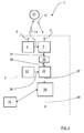
Figure 2 , theradar system 3 comprises atransceiver arrangement 5 that is arranged for generating and transmitting sweep signals in the form of FMCW (Frequency Modulated Continuous Wave) chirp signals 11, and to receive reflectedsignals 12, where the transmitted chirp signals 11 have been reflected by anobject 31. - The
transceiver arrangement 5 comprises atransmitter arrangement 4 with a transmit antenna arrangement 8, areceiver arrangement 7 with areceiver antenna arrangement 9, an Analog to Digital Converter (ADC)arrangement 32 and sampling and timing arrangement 33. - More in detail, with reference to
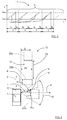
Figure 3 , there is transmittedsignal 11, constituting a so-called chirp signal that is in the form of a continuous sinusoid where the frequency varies from a first frequency fstart to a second frequency fstop over the course of a ramp, where the magnitude of the first frequency fstart falls below the magnitude of the second frequency fstop. - The
chirp signal 11 comprises repeating cycles of a plurality N of frequency ramps r where a radar cycle for thechirp signal 4 lasts for a certain radar cycle time tc, each ramp lasting a certain ramp time tr and where there is a certain delay time tD between adjacent ramps r. Each ramp r has a period time T that equals a sum of the ramp time tr and the delay time tD. The delay time tD may be essentially zero. - With renewed reference to
Figure 2 , the reflected signals 12 are received by thereceiver arrangement 7 via thereceiver antenna arrangement 9. The receivedsignals 12, thus constituted by reflected radar echoes, are then mixed with the transmittedchirp signals 11 in thereceiver arrangement 9. This may be a single channel mixer, or a two channel mixer comprising both in-phase and quadrature components. In this way, an IF (Intermediate Frequency) signal 34 is acquired, which may be real or, in the case of quadrature mixer, imaginary. TheIF signal 34 is filtered in anIF filter 35 such that a filtered IFsignal 36 is acquired. - The frequency of the filtered IF
signal 36 relates to the target distance and is transferred to thecorresponding ADC arrangement 32, where the filtered IFsignal 36 is sampled at a certain predetermined sampling frequency fs and converted to a digital IFsignal 37 comprising sample points in a previously known manner, the sampling frequency fs being provided in the form of a sampling andtiming signal 38 produced by the sampling and timing arrangement 33 that is connected to theADC arrangement 32. - The
ADC arrangement 32 is connected to aDSP arrangement 39 that is adapted for radar signal by means of well-known FFT (Fast Fourier Transform) processing of an FMCW radar signal to extract objects within the field ofview 10. For such processing normally a range FFT function is arranged to convert the filtered digital IFsignal 36 to a range domain, and a Doppler FFT function is arranged to combine the results from successive chirp signal ramps, or other suitable Doppler radar cycles, into the Doppler domain. This results in anoutput 40 comprising Range-Doppler matrices that are transferred for further processing, which is not further discussed here, many examples of such further processing being well-known in the art. - The
radar system 3 also comprises acontrol unit 15. Thecontrol unit 15 should be regarded as a control unit arrangement that is in the form of one unit or several units that either co-operate or handle different tasks more or less independently. In the case of several units, these may be placed adjacent to each other, or in a distributed manner. The control unit is here shown connected to theDSP arrangement 39, of course this is not necessary; thecontrol unit 15 may be connected to several components and/or other control units. - With reference also to
Figure 1 , when in use, thetransmitter antenna arrangement 6 sends a signal laterally in the pointing direction P when thevehicle 1 runs past aparking 13, theradar system 3 having said certain field ofview 10 that passes along theparking 13. Theradar system 3 then receives echoes of the transmitted signals 11 by means of the receiver antenna arrangement 8 where the transmitted signals 11 have been reflected by anobject 31. The field ofview 10 corresponds to the beamwidth of theantenna arrangements - The above is repeated as many times as necessary at a predetermined frequency band, while the vehicle moves along the
parking 13 in the forward direction F, to obtain required information regarding possible parking spots. - According to the present disclosure, with reference also to
Figure 4 , each measure results in ameasuring point 14, where the control unit is arranged to use each measuringpoint 14 to form aspectrum density map 30, as indicated inFigure 7 , for each radar cycle along the main field ofview 10. As thevehicle 1 moves in the forward direction F, the main field ofview 10 moves along, and in this manner a complete spectrum density mapping of a certain area is obtained by combining several spectrum density maps from a corresponding plurality of radar cycles. Thecontrol unit 15 is thus arranged to combine at least two spectrum density maps to form a combined spectrum density map. - In this context, a radar cycle is one observation phase in which the radar acquires data, processes the date on several signal processing levels and sends out available results. This can be a fixed time interval (i.e. 40 to 60 milliseconds), or it can be a dynamic time interval depending on environment conditions and processing load.
- According to some aspects, the
spectrum density map 30 comprises range and angle spectrum data. Generally, thespectrum density map 30 comprises a calculated returned amount of energy from stationary measuring points. The data comprised in thespectrum density map 30 may be taken from either the range FFT function or the Doppler FFT function. - Each measuring point is thus detected several times as the
vehicle 1 moves in the forward direction F during a plurality of sample times, where at each sample time measuring points with the field ofview 10 are detected. For each such detection, the position of ameasuring point 14 is determined with respect to the vehicle's position by a target distance T, running between the measuringpoint 14 and the transmitter antenna arrangement, and a target angle ϕ running between the forward direction F and anextension 18 of the target distance T. As the vehicle approaches acertain measuring point 14, the target angle ϕ increases. - According to some aspects, a stationary target, such as a
measurement point 14, has a relative velocity vrel that is calculated by thecontrol unit 15 as the vehicle velocity vF times cosine for the target angle ϕ, i.e. vrel = vF *cos (ϕ). From the relative velocity vrel a phase difference α between two adjacent FMCW ramps is calculated by thecontrol unit 15, as will be described below. - Only stationary objects will present the same phase difference +α for all ramps r in a radar cycle for a certain target angle ϕ. For each ramp r, each measurement point results in a complex number that is derived from the range FFT function by means of the
control unit 15 and turns with the phase difference α from ramp to ramp. Each complex number comprises a phase and a magnitude, where the direction turns with the phase difference α between adjacent ramps. With knowledge of the phase difference α, thecontrol unit 15 is according to some aspects arranged to rotate all measurement vectors for a certain object using the calculated phase difference α such that they are added in phase. This means that consecutive measurements vectors are rotated an integer k times the phase difference α, where the integer k runs from 0 to V-1 where V is the number of measurement vectors. - This is illustrated in
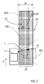
Figure 6 , where there is a first vector v1, a second vector v2, a third vector v3 and a fourth vector v4. The first vector v1 is used as a reference vector and is rotated 0°, such that the rotated first vector v1 equals the first vector v1. The second vector v2 has a phase difference α relative the first vector v1 and is rotated back α to form a rotated second vector v2', the third vector v3 has a phase difference α relative the second vector v2 and is rotated back 2α to form a rotated third vector v3', and the fourth vector v4 has a phase difference α relative the third vector v3 and is rotated back 3α to form a rotated fourth vector v4'. The first vector v1 and the rotated vectors v2', v3', v4' all add in phase since the measurement point is stationary. InFigure 6 , only a few vectors are shown for explanatory reasons. - Generally, this means that consecutive measurements vectors v1, v2, v3, v4 ... vV are rotated an integer k times the phase difference α, where the integer k runs from 0 to V-1 where V is the number of measurement vectors.
- In this manner, only stationary objects are considered, moving objects will not result in measurement vectors that add in phase; over time such objects will result in measurement vectors that more or less cancel out, and thus only stationary objects will be considered. This is done for each angle in the acquired range and angle spectrum. For each receive channel, a range and angle spectrum is formed in this manner. In this context, the term "stationary" refers to stationary with respect the
vehicle radar system 3. - The phase difference α between adjacent ramps is calculated as


- Furthermore, according to some aspects, all receive channels, corresponding to the
receiver antenna devices - As illustrated in
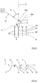
Figure 5 , thereceiver antenna arrangement 9 comprises four receiver antenna devices; a first receiver antenna device 9a, a secondreceiver antenna device 9b, a thirdreceiver antenna device 9c and a fourthreceiver antenna device 9d. A reflectedsignal 12 comprises a wavefront that here is illustrated at two times, constituting afirst time wavefront 26a and asecond time wavefront 26b, thefirst time wavefront 26a and thesecond time wavefront 26b thus illustrating the same wavefront at two different times. - There is a receiver antenna aperture plane A and a boresight direction B that runs perpendicular to the receiver antenna aperture plane A. The reflected
signal 12 has an inclination β relative the boresight direction B, where the inclination β constitutes a direction of arrival (DOA), β constituting a DOA angle. - The DOA angle β results in that the
first time wavefront 26a reaches the first receiver antenna device 9a first, then the secondreceiver antenna device 9b and so on. There is thus a delay time Δt that occurs between when thefirst time wavefront 26a reaches the first receiver antenna device 9a and when thesecond time wavefront 26b reaches the secondreceiver antenna device 9b, and this delay time Δt corresponds to a certain delay distance d and a certain delay phase ξ, and depends on the DOA angle β. - Since the angle of each stationary measurement point is known, according to some aspects, the delay time Δt is calculated by the
control unit 15, and then the corresponding delay phase difference ξ is derived. The calculation is made according to:
Figure 5 between the first receiver antenna device 9a and the secondreceiver antenna device 9b, and where λc is a center frequency wavelength, i.e.
- Equation (4) follows from trigonometry in
Figure 5 . - The processing is done on all receive channels separately by adding a phase rotation that is introduced due to the Doppler effect, where there is a phase rotation performed for a determined complex signal at a specific antenna. As stationary objects having different angles to the system have different relative velocities, this separates the energy received from objects at different angles.
- By means of the present disclosure, as shown in
Figure 7 , a completespectrum density map 30 is acquired in aCartesian grid 24 that is combined from all cycles during the passing of the main field ofview 10 and having a certain depth R, providing a dense estimation of energy returns 14, 25 (only a few indicated in the Figure) instead of single separate detection points. An energy return is any type of received reflection, for example from ameasuring point 14. In this way, a two-dimensional detailed top view of theparking 13 is obtained, where all energy returns are accounted for. - Suitably, according to some aspects, a camera device and image processing algorithms are used for identification and classification of objects. In
Figure 4 andFigure 7 , threeobjects - An advantage of keeping all information is that for example a rear light reflector provides a relatively high degree of reflection, but does in itself not provide all data necessary for determining the extension of a vehicle. A radar system that focusses on detections having high degrees of reflection and discards other detections will lose valuable information.
- By means of the now acquired range and angle spectrum density map, parking spaces may be detected with a high degree of accuracy, i.e. it may be determined whether there is a
useful parking spot 21 available, i.e. a spot which has asufficient depth 22 andsufficient length 23 admit parking of thevehicle 1. - For reasons of clarity, not all measures of
Figure 3 are indicated inFigure 5 . - According to some aspects, there may instead be a forward-looking radar system, or several radar systems covering several fields around the vehicle. Such a coverage is desired for automatic driver assistance systems, where the control and driving of the
vehicle 1 is more or less automated. - With reference to
Figure 8 , the present disclosure also relates to a method for a vehicleDoppler radar system 3 that is used in avehicle 1 having a forward running direction F. The method comprises the steps of: - 42: Transmitting signals 11.
- 43: Receiving reflected signals 12.
- 44: Obtaining a plurality of measure results from the received reflected
signals 12 along a main field ofview 10 during at least two radar cycles. - 45: For each radar cycle, forming a
spectrum density map 30 from measuringpoints 14 along the main field ofview 10, where each measure result results in ameasuring point 14. - 46: Combining at least two spectrum density maps to form a combined spectrum density map.
- According to an example, for each measuring
point 14, the method further comprises: - 47: Determining a measurement vector v1, v2, v3, v4, comprising direction and magnitude, for each FMCW ramp r.
- 48: Determining a phase difference α between adjacent FMCW ramps r.
- 49: Performing a rotation of measurement vectors v1, v2, v3, v4 using a number of said phase difference α, such that the rotated measurement vectors v1, v2', v3', v4' that correspond to stationary measuring points 14 add in phase.
- The present disclosure is not limited to the examples above, but may vary freely within the scope of the appended claims. For example, the radar system may be implemented in any type of vehicle such as cars, trucks and buses as well as boats and aircraft.
- All drawings are simplified, only showing parts that are considered relevant for an adequate description of the present disclosure. It is understood that the general design of radar systems of this kind is well-known in the art.
- The constitution of the antenna devices comprised in the
transmitter antenna arrangement 6 and thereceiver antenna arrangement 9 may be of any suitable design, such as slot antennas of patch antennas. Thetransmitter antenna arrangement 6 andreceiver antenna arrangement 9 may be combined in one antenna arrangement that is arranged for both transmission and reception by means of, for example, time division. - The number of antenna devices comprised in the
transmitter antenna arrangement 6 and thereceiver antenna arrangement 9 may vary; there should be at least one transmitter antenna device and at least onereceiver antenna device - Generally, the present disclosure relates to a vehicle FMCW (Frequency Modulated Continuous Wave)
Doppler radar system 3 comprising atransmitter arrangement 4, areceiver arrangement 7 and at least onecontrol unit 15, theradar system 3 being arranged to be mounted in avehicle 1, where thetransmitter arrangement 4 comprises atransmitter antenna arrangement 6 arranged for transmittingsignals 11, and where thereceiver arrangement 7 comprises areceiver antenna arrangement 9 arranged for receiving reflectedsignals 12, theradar system 3 being arranged to obtain a plurality of measure results from the received reflectedsignals 12 along a main field ofview 10 during at least two radar cycles where each radar cycle comprises a plurality of FMCW ramps. For each radar cycle, saidcontrol unit 15 is arranged to form aspectrum density map 30 from measuringpoints 14 along the main field ofview 10, where each measure result results in ameasuring point 14, where saidcontrol unit 15 is arranged to combine at least two spectrum density maps to form a combined spectrum density map. - According to an example, each
spectrum density map 30 comprises range and angle spectrum. - According to an example, said
control unit 15 is arranged to calculate eachspectrum density map 30 by means of either data from a range FFT (Fast Fourier Transform) function or a Doppler FFT function, where theradar system 3 comprises a DSP (Digital Signal Processor) function 39 that is arranged to perform said FFT functions. - According to an example, said
control unit 15 is arranged to determine a phase difference α between adjacent FMCW ramps r for each measuringpoint 14, to determine a measurement vector v1, v2, v3, v4 comprising direction and magnitude for each measuringpoint 14, and to perform a rotation of each measurement vector v1, v2, v3, v4 with said phase difference α such that the rotated measurement vectors v1', v2', v3', v4' that correspond to stationary measuring points 14 add in phase. - According to an example, the
receiver antenna arrangement 9 comprises at least tworeceiver antenna devices control unit 15 is arranged to combine the receive channels of saidreceiver antenna devices signals 12 reach adjacentreceiver antenna devices control unit 15 is arranged to compensate for said delay phase ξ by means of a compensating rotation of a determined complex signal for eachantenna device - According to an example, the
radar system 3 is arranged to determine whether there is sufficient parking space available. - Generally, the present disclosure also relates to a method for a vehicle FMCW (Frequency Modulated Continuous Wave)
Doppler radar system 3 that is used in avehicle 1, where the method comprises: - 42: Transmitting signals 11.
- 43: Receiving reflected signals 12.
- 44: Obtaining a plurality of measure results from the received reflected
signals 12 along a main field ofview 10 during at least two radar cycles. - 45: For each radar cycle, forming a
spectrum density map 30 from measuringpoints 14 along the main field ofview 10, where each measure result results in ameasuring point 14. - 46: Combining at least two spectrum density maps to form a combined spectrum density map.
- According to an example, each
spectrum density map 30 uses range and angle spectrum. - According to an example, each
spectrum density map 30 is calculated by either using data from a range FFT (Fast Fourier Transform) function or using a Doppler FFT function. - According to an example, for each measuring
point 14, the method further comprises: - 47: Determining a measurement vector v1, v2, v3, v4, comprising direction and magnitude, for each FMCW ramp r.
- 48: Determining a phase difference α between adjacent FMCW ramps r.
- 49: Performing a rotation of measurement vectors v1, v2, v3, v4 using a number of said phase difference α, such that the rotated measurement vectors v1, v2', v3', v4' that correspond to stationary measuring points 14 add in phase.
- According to an example, the
radar system 3 uses at least tworeceiver antenna devices receiver antenna devices signals 12 reach adjacentreceiver antenna devices antenna device - According to an example, the method comprises determining whether there is sufficient parking space available.
Claims (12)
- A vehicle FMCW, Frequency Modulated Continuous Wave, Doppler radar system (3) comprising a transmitter arrangement (4), a receiver arrangement (7) and at least one control unit (15), the radar system (3) being arranged to be mounted in a vehicle (1), where the transmitter arrangement (4) comprises a transmitter antenna arrangement (6) arranged for transmitting signals (11), and where the receiver arrangement (7) comprises a receiver antenna arrangement (9) arranged for receiving reflected signals (12), the radar system (3) being arranged to obtain a plurality of measure results from the received reflected signals (12) along a main field of view (10) during at least two radar cycles where each radar cycle comprises a plurality of FMCW ramps, characterized in that for each radar cycle, said control unit (15) is arranged to form a spectrum density map (30) from measuring points (14) along the main field of view (10), where each measure result results in a measuring point (14), where said control unit (15) is arranged to combine at least two spectrum density maps to form a combined spectrum density map.
- A radar system according to claim 1, characterized in that each spectrum density map (30) comprises range and angle spectrum.
- A radar system according to any one of the claims 1 or 2, characterized in that said control unit (15) is arranged to calculate each spectrum density map (30) by means of either data from a range FFT, Fast Fourier Transform, function or a Doppler FFT function, where the radar system (3) comprises a DSP, Digital Signal Processor, function (39) that is arranged to perform said FFT functions.
- A radar system according to any one of the previous claims, characterized in that said control unit (15) is arranged to determine a phase difference (α) between adjacent FMCW ramps (r) for each measuring point (14), to determine a measurement vector (v1, v2, v3, v4) comprising direction and magnitude for each measuring point (14), and to perform a rotation of each measurement vector (v1, v2, v3, v4) with said phase difference (α) such that the rotated measurement vectors (v1', v2', v3', v4') that correspond to stationary measuring points (14) add in phase.
- A radar system according to any one of the previous claims, characterized in that the receiver antenna arrangement (9) comprises at least two receiver antenna devices (9a, 9b, 9c, 9d) with corresponding receive channels, where said control unit (15) is arranged to combine the receive channels of said receiver antenna devices (9a, 9b, 9c, 9d) by means of beamforming, where each wavefront (12a, 12b) corresponding to the received reflected signals (12) reach adjacent receiver antenna devices (9a, 9b, 9c, 9d) with a delay time (Δt) that corresponds to a certain delay distance (d) and a certain delay phase (ξ) that depends on a direction of arrival, DOA, angle (β), where said control unit (15) is arranged to compensate for said delay phase (ξ) by means of a compensating rotation of a determined complex signal for each antenna device (9a, 9b, 9c, 9d).
- A radar system according to any one of the previous claims, characterized in that the radar system (3) is arranged to determine whether there is sufficient parking space available.
- A method for a vehicle FMCW, Frequency Modulated Continuous Wave, Doppler radar system (3) that is used in a vehicle (1), where the method comprises:(42) transmitting signals (11);(43) receiving reflected signals (12); and(44) obtaining a plurality of measure results from the received reflected signals (12) along a main field of view (10) during at least two radar cycles,characterized in that the method further comprises:(45) For each radar cycle, forming a spectrum density map (30) from measuring points (14) along the main field of view (10), where each measure result results in a measuring point (14); and(46) combining at least two spectrum density maps (30) to form a combined spectrum density map.
- The method according to claim 7, characterized in that each spectrum density map (30) uses range and angle spectrum.
- The method according to any one of the claims 7 or 8, characterized in that each spectrum density map (30) is calculated by either using data from a range FFT, Fast Fourier Transform, function or using a Doppler FFT function.
- The method according to any one of the claims 7-9, characterized in that, for each measuring point (14), the method further comprises:(47) determining a measurement vector (v1, v2, v3, v4), comprising direction and magnitude, for each FMCW ramp (r);(48) determining a phase difference (α) between adjacent FMCW ramps (r); and(49) performing a rotation of measurement vectors (v1, v2, v3, v4) using a number of said phase difference (α), such that the rotated measurement vectors (v1, v2', v3', v4') that correspond to stationary measuring points (14) add in phase.
- The method according to any one of the claims 7-10, characterized in that the radar system (3) uses at least two receiver antenna devices (9a, 9b, 9c, 9d) with corresponding receive channels, where the method comprises combining the receive channels of said receiver antenna devices (9a, 9b, 9c, 9d) using beamforming, where each wavefront (12a, 12b) corresponding to the received reflected signals (12) reach adjacent receiver antenna devices (9a, 9b, 9c, 9d) with a delay time (Δt) that corresponds to a certain delay distance (d) and a certain delay phase (ξ) that depends on a direction of arrival, DOA, angle (β), where the method further comprises compensating for said delay phase (ξ) by performing a compensating rotation of a determined complex signal for each antenna device (9a, 9b, 9c, 9d).
- The method according to any one of the claims 1-11, characterized in that the method comprises determining whether there is sufficient parking space available.
Priority Applications (7)
| Application Number | Priority Date | Filing Date | Title |
|---|---|---|---|
| EP16177581.2A EP3264131A1 (en) | 2016-07-01 | 2016-07-01 | A vehicle radar for environmental detection |
| EP21175247.2A EP3907529A1 (en) | 2016-07-01 | 2016-07-01 | A vehicle radar for environmental detection |
| KR1020197000017A KR102176025B1 (en) | 2016-07-01 | 2017-06-29 | Vehicle radar for environmental detection |
| JP2018567748A JP6751993B2 (en) | 2016-07-01 | 2017-06-29 | Vehicle radar for environmental detection |
| CN201780040947.7A CN109477892B (en) | 2016-07-01 | 2017-06-29 | Vehicle radar for environmental detection |
| PCT/EP2017/066152 WO2018002233A1 (en) | 2016-07-01 | 2017-06-29 | A vehicle radar for environmental detection |
| US16/313,767 US11105919B2 (en) | 2016-07-01 | 2017-06-29 | Vehicle radar for environmental detection |
Applications Claiming Priority (1)
| Application Number | Priority Date | Filing Date | Title |
|---|---|---|---|
| EP16177581.2A EP3264131A1 (en) | 2016-07-01 | 2016-07-01 | A vehicle radar for environmental detection |
Related Child Applications (1)
| Application Number | Title | Priority Date | Filing Date |
|---|---|---|---|
| EP21175247.2A Division EP3907529A1 (en) | 2016-07-01 | 2016-07-01 | A vehicle radar for environmental detection |
Publications (1)
| Publication Number | Publication Date |
|---|---|
| EP3264131A1 true EP3264131A1 (en) | 2018-01-03 |
Family
ID=56292618
Family Applications (2)
| Application Number | Title | Priority Date | Filing Date |
|---|---|---|---|
| EP21175247.2A Ceased EP3907529A1 (en) | 2016-07-01 | 2016-07-01 | A vehicle radar for environmental detection |
| EP16177581.2A Ceased EP3264131A1 (en) | 2016-07-01 | 2016-07-01 | A vehicle radar for environmental detection |
Family Applications Before (1)
| Application Number | Title | Priority Date | Filing Date |
|---|---|---|---|
| EP21175247.2A Ceased EP3907529A1 (en) | 2016-07-01 | 2016-07-01 | A vehicle radar for environmental detection |
Country Status (6)
| Country | Link |
|---|---|
| US (1) | US11105919B2 (en) |
| EP (2) | EP3907529A1 (en) |
| JP (1) | JP6751993B2 (en) |
| KR (1) | KR102176025B1 (en) |
| CN (1) | CN109477892B (en) |
| WO (1) | WO2018002233A1 (en) |
Cited By (2)
| Publication number | Priority date | Publication date | Assignee | Title |
|---|---|---|---|---|
| CN111783595A (en) * | 2020-06-24 | 2020-10-16 | 中国第一汽车股份有限公司 | Vehicle parking method and device, vehicle-mounted equipment and storage medium |
| RU2761928C1 (en) * | 2021-03-26 | 2021-12-14 | Общество с ограниченной ответственностью "Научно-производственное предприятие "ИТЭЛМА" (ООО "НПП "ИТЭЛМА") | Radar sensor for vehicle collision prevention |
Families Citing this family (13)
| Publication number | Priority date | Publication date | Assignee | Title |
|---|---|---|---|---|
| DE102018104243B3 (en) * | 2018-02-26 | 2019-05-16 | Autoliv Development Ab | Method and system for detecting parking spaces suitable for a vehicle |
| DE112019003435T5 (en) * | 2018-08-07 | 2021-04-01 | Murata Manufacturing Co., Ltd. | Radar device |
| DE112019005851T5 (en) | 2018-11-22 | 2021-09-09 | Murata Manufacturing Co., Ltd. | RADAR DEVICE, VEHICLE AND OBJECT POSITION DETECTION METHODS |
| KR102708716B1 (en) * | 2019-02-18 | 2024-09-23 | 삼성메디슨 주식회사 | Analog beam former |
| US11196171B2 (en) * | 2019-07-23 | 2021-12-07 | Veoneer Us, Inc. | Combined waveguide and antenna structures and related sensor assemblies |
| EP3779505B1 (en) | 2019-08-13 | 2024-06-12 | Magna Electronics Sweden AB | Detection of blocked radar sensor |
| DE102019220238A1 (en) * | 2019-12-19 | 2021-06-24 | Robert Bosch Gmbh | Calibration of a cooperative radar sensor system |
| KR102982738B1 (en) | 2019-12-26 | 2026-06-26 | 삼성전자주식회사 | Method and device to process radar signal |
| KR20210101957A (en) | 2020-02-11 | 2021-08-19 | 삼성전자주식회사 | Method and apparatus for detecting velocity of object in radar system |
| DE102020109502A1 (en) * | 2020-04-06 | 2021-10-07 | HELLA GmbH & Co. KGaA | Method for determining an angle information |
| CN112180372A (en) * | 2020-08-19 | 2021-01-05 | 福瑞泰克智能系统有限公司 | A target detection method, device and radar system based on dual-angle radar |
| JP7166496B1 (en) * | 2022-02-24 | 2022-11-07 | 三菱電機株式会社 | radar system |
| EP4469825A4 (en) * | 2022-03-09 | 2026-01-21 | Sensata Technologies Inc | WIDE-FIELD VIEW ANTENNA FOR BLIND SPOT DETECTION |
Citations (4)
| Publication number | Priority date | Publication date | Assignee | Title |
|---|---|---|---|---|
| WO2015078682A1 (en) * | 2013-11-26 | 2015-06-04 | Thales | Anticollision radar, especially for an aircraft when taxiing, and anticollision system |
| EP2881754A1 (en) | 2013-12-06 | 2015-06-10 | Autoliv Development AB | Vehicle radar for environmental detection |
| US20160018511A1 (en) * | 2014-07-17 | 2016-01-21 | Texas Instruments Incorporated | Distributed Radar Signal Processing in a Radar System |
| DE102014218092A1 (en) * | 2014-09-10 | 2016-03-10 | Volkswagen Aktiengesellschaft | Creating an image of the environment of a motor vehicle and determining the relative speed between the motor vehicle and objects in the environment |
Family Cites Families (17)
| Publication number | Priority date | Publication date | Assignee | Title |
|---|---|---|---|---|
| JP2003202373A (en) * | 2002-01-07 | 2003-07-18 | Omron Corp | Moving object detecting device and moving object detecting method |
| DE10220837A1 (en) * | 2002-05-08 | 2003-11-27 | Daimler Chrysler Ag | Device for parking space search by means of radar |
| DE102004052521A1 (en) * | 2004-10-29 | 2006-05-04 | Robert Bosch Gmbh | FMCW radar with stationary target suppression |
| JP4561507B2 (en) * | 2005-07-08 | 2010-10-13 | 株式会社デンソー | Road shape recognition device |
| US7400290B2 (en) * | 2005-12-30 | 2008-07-15 | Valeo Raytheon Systems, Inc. | Vehicle radar system having multiple operating modes |
| EP2057480B1 (en) * | 2006-10-06 | 2014-06-04 | ADC Automotive Distance Control Systems GmbH | Radar system for detecting surroundings with compensation of interfering signals |
| US7639171B2 (en) * | 2007-09-27 | 2009-12-29 | Delphi Technologies, Inc. | Radar system and method of digital beamforming |
| JP5468304B2 (en) * | 2009-05-20 | 2014-04-09 | 株式会社東芝 | Radar equipment |
| JP2011220779A (en) * | 2010-04-07 | 2011-11-04 | Toyota Motor Corp | Obstacle detection device |
| US9594159B2 (en) * | 2013-07-15 | 2017-03-14 | Texas Instruments Incorporated | 2-D object detection in radar applications |
| DE102014213190A1 (en) * | 2014-06-10 | 2015-12-17 | Robert Bosch Gmbh | Method for object location with an FMCW radar |
| JP6406601B2 (en) * | 2014-08-05 | 2018-10-17 | パナソニックIpマネジメント株式会社 | Radar apparatus and object detection method |
| US9470777B2 (en) * | 2014-09-19 | 2016-10-18 | Delphi Technologies, Inc. | Radar system for automated vehicle with phase change based target catagorization |
| US9784820B2 (en) * | 2014-09-19 | 2017-10-10 | Delphi Technologies, Inc. | Radar system with phase based multi-target detection |
| US10061016B2 (en) * | 2014-12-29 | 2018-08-28 | Texas Instruments Incorporated | Phase noise measurement in a cascaded radar system |
| EP3098623A1 (en) * | 2015-05-25 | 2016-11-30 | Autoliv Development AB | A vehicle radar system |
| US10775489B2 (en) * | 2016-12-15 | 2020-09-15 | Texas Instruments Incorporated | Maximum measurable velocity in frequency modulated continuous wave (FMCW) radar |
-
2016
- 2016-07-01 EP EP21175247.2A patent/EP3907529A1/en not_active Ceased
- 2016-07-01 EP EP16177581.2A patent/EP3264131A1/en not_active Ceased
-
2017
- 2017-06-29 WO PCT/EP2017/066152 patent/WO2018002233A1/en not_active Ceased
- 2017-06-29 US US16/313,767 patent/US11105919B2/en active Active
- 2017-06-29 KR KR1020197000017A patent/KR102176025B1/en active Active
- 2017-06-29 JP JP2018567748A patent/JP6751993B2/en active Active
- 2017-06-29 CN CN201780040947.7A patent/CN109477892B/en active Active
Patent Citations (4)
| Publication number | Priority date | Publication date | Assignee | Title |
|---|---|---|---|---|
| WO2015078682A1 (en) * | 2013-11-26 | 2015-06-04 | Thales | Anticollision radar, especially for an aircraft when taxiing, and anticollision system |
| EP2881754A1 (en) | 2013-12-06 | 2015-06-10 | Autoliv Development AB | Vehicle radar for environmental detection |
| US20160018511A1 (en) * | 2014-07-17 | 2016-01-21 | Texas Instruments Incorporated | Distributed Radar Signal Processing in a Radar System |
| DE102014218092A1 (en) * | 2014-09-10 | 2016-03-10 | Volkswagen Aktiengesellschaft | Creating an image of the environment of a motor vehicle and determining the relative speed between the motor vehicle and objects in the environment |
Cited By (2)
| Publication number | Priority date | Publication date | Assignee | Title |
|---|---|---|---|---|
| CN111783595A (en) * | 2020-06-24 | 2020-10-16 | 中国第一汽车股份有限公司 | Vehicle parking method and device, vehicle-mounted equipment and storage medium |
| RU2761928C1 (en) * | 2021-03-26 | 2021-12-14 | Общество с ограниченной ответственностью "Научно-производственное предприятие "ИТЭЛМА" (ООО "НПП "ИТЭЛМА") | Radar sensor for vehicle collision prevention |
Also Published As
| Publication number | Publication date |
|---|---|
| CN109477892B (en) | 2023-06-23 |
| JP2019525145A (en) | 2019-09-05 |
| KR102176025B1 (en) | 2020-11-06 |
| EP3907529A1 (en) | 2021-11-10 |
| WO2018002233A1 (en) | 2018-01-04 |
| JP6751993B2 (en) | 2020-09-09 |
| US11105919B2 (en) | 2021-08-31 |
| KR20190014061A (en) | 2019-02-11 |
| CN109477892A (en) | 2019-03-15 |
| US20190170870A1 (en) | 2019-06-06 |
Similar Documents
| Publication | Publication Date | Title |
|---|---|---|
| US11105919B2 (en) | Vehicle radar for environmental detection | |
| US11249180B2 (en) | Method and device for ascertaining transverse relative velocity components of radar targets | |
| US5818383A (en) | Interferometric moving vehicle imaging apparatus and method | |
| EP3746809B1 (en) | Systems and methods for virtual aperture radar tracking | |
| US11762084B2 (en) | Vehicle radar system | |
| US20050179579A1 (en) | Radar receiver motion compensation system and method | |
| JP3821688B2 (en) | Radar equipment | |
| EP3098623A1 (en) | A vehicle radar system | |
| US11280882B2 (en) | Method and radar device for ascertaining radial relative acceleration of at least one target | |
| US11841416B2 (en) | Radar system for a vehicle | |
| US11493596B2 (en) | Estimation of cartesian velocities of extended radar objects using a radar sensor | |
| CN111712722B (en) | Estimation of the lateral or Cartesian velocity of a point target using a radar sensor | |
| WO2017050798A1 (en) | A vehicle synthetic aperture radar system | |
| EP3460512B1 (en) | A vehicle radar for environmental detection | |
| US5559516A (en) | Dual cancellation interferometric AMTI radar | |
| JP7224292B2 (en) | Radar device and automobile equipped with it | |
| US6982668B1 (en) | Tangential velocity measurement using interferometric MTI radar | |
| EP4459315A1 (en) | Method for calibration of a radar sensor | |
| US11333754B2 (en) | Detection of parking row orientation | |
| JP3865761B2 (en) | Radar equipment | |
| Berens et al. | First multi-channel results of the airborne sar/gmti sensor pamir-ka | |
| EP4624991A1 (en) | A method for determining a target information of a radar target based on an coherent signal processing chain, radar system and motor vehicle | |
| JPS61140883A (en) | High resolving power radar for tracking target |
Legal Events
| Date | Code | Title | Description |
|---|---|---|---|
| PUAI | Public reference made under article 153(3) epc to a published international application that has entered the european phase |
Free format text: ORIGINAL CODE: 0009012 |
|
| STAA | Information on the status of an ep patent application or granted ep patent |
Free format text: STATUS: THE APPLICATION HAS BEEN PUBLISHED |
|
| AK | Designated contracting states |
Kind code of ref document: A1 Designated state(s): AL AT BE BG CH CY CZ DE DK EE ES FI FR GB GR HR HU IE IS IT LI LT LU LV MC MK MT NL NO PL PT RO RS SE SI SK SM TR |
|
| AX | Request for extension of the european patent |
Extension state: BA ME |
|
| STAA | Information on the status of an ep patent application or granted ep patent |
Free format text: STATUS: REQUEST FOR EXAMINATION WAS MADE |
|
| RAP1 | Party data changed (applicant data changed or rights of an application transferred) |
Owner name: VEONEER SWEDEN AB |
|
| 17P | Request for examination filed |
Effective date: 20180628 |
|
| RBV | Designated contracting states (corrected) |
Designated state(s): AL AT BE BG CH CY CZ DE DK EE ES FI FR GB GR HR HU IE IS IT LI LT LU LV MC MK MT NL NO PL PT RO RS SE SI SK SM TR |
|
| STAA | Information on the status of an ep patent application or granted ep patent |
Free format text: STATUS: EXAMINATION IS IN PROGRESS |
|
| 17Q | First examination report despatched |
Effective date: 20190625 |
|
| STAA | Information on the status of an ep patent application or granted ep patent |
Free format text: STATUS: THE APPLICATION HAS BEEN REFUSED |
|
| 18R | Application refused |
Effective date: 20210627 |