EP3263939A1 - Constant velocity universal joint - Google Patents
Constant velocity universal joint Download PDFInfo
- Publication number
- EP3263939A1 EP3263939A1 EP16755105.0A EP16755105A EP3263939A1 EP 3263939 A1 EP3263939 A1 EP 3263939A1 EP 16755105 A EP16755105 A EP 16755105A EP 3263939 A1 EP3263939 A1 EP 3263939A1
- Authority
- EP
- European Patent Office
- Prior art keywords
- boot
- mounting portion
- joint member
- diameter mounting
- receiving portion
- Prior art date
- Legal status (The legal status is an assumption and is not a legal conclusion. Google has not performed a legal analysis and makes no representation as to the accuracy of the status listed.)
- Granted
Links
Images


Classifications
-
- F—MECHANICAL ENGINEERING; LIGHTING; HEATING; WEAPONS; BLASTING
- F16—ENGINEERING ELEMENTS AND UNITS; GENERAL MEASURES FOR PRODUCING AND MAINTAINING EFFECTIVE FUNCTIONING OF MACHINES OR INSTALLATIONS; THERMAL INSULATION IN GENERAL
- F16D—COUPLINGS FOR TRANSMITTING ROTATION; CLUTCHES; BRAKES
- F16D3/00—Yielding couplings, i.e. with means permitting movement between the connected parts during the drive
- F16D3/84—Shrouds, e.g. casings, covers; Sealing means specially adapted therefor
- F16D3/843—Shrouds, e.g. casings, covers; Sealing means specially adapted therefor enclosed covers
- F16D3/845—Shrouds, e.g. casings, covers; Sealing means specially adapted therefor enclosed covers allowing relative movement of joint parts due to the flexing of the cover
-
- F—MECHANICAL ENGINEERING; LIGHTING; HEATING; WEAPONS; BLASTING
- F16—ENGINEERING ELEMENTS AND UNITS; GENERAL MEASURES FOR PRODUCING AND MAINTAINING EFFECTIVE FUNCTIONING OF MACHINES OR INSTALLATIONS; THERMAL INSULATION IN GENERAL
- F16D—COUPLINGS FOR TRANSMITTING ROTATION; CLUTCHES; BRAKES
- F16D3/00—Yielding couplings, i.e. with means permitting movement between the connected parts during the drive
- F16D3/84—Shrouds, e.g. casings, covers; Sealing means specially adapted therefor
-
- F—MECHANICAL ENGINEERING; LIGHTING; HEATING; WEAPONS; BLASTING
- F16—ENGINEERING ELEMENTS AND UNITS; GENERAL MEASURES FOR PRODUCING AND MAINTAINING EFFECTIVE FUNCTIONING OF MACHINES OR INSTALLATIONS; THERMAL INSULATION IN GENERAL
- F16D—COUPLINGS FOR TRANSMITTING ROTATION; CLUTCHES; BRAKES
- F16D3/00—Yielding couplings, i.e. with means permitting movement between the connected parts during the drive
- F16D3/16—Universal joints in which flexibility is produced by means of pivots or sliding or rolling connecting parts
- F16D3/24—Universal joints in which flexibility is produced by means of pivots or sliding or rolling connecting parts comprising balls, rollers, or the like between overlapping driving faces, e.g. cogs, on both coupling parts
-
- F—MECHANICAL ENGINEERING; LIGHTING; HEATING; WEAPONS; BLASTING
- F16—ENGINEERING ELEMENTS AND UNITS; GENERAL MEASURES FOR PRODUCING AND MAINTAINING EFFECTIVE FUNCTIONING OF MACHINES OR INSTALLATIONS; THERMAL INSULATION IN GENERAL
- F16J—PISTONS; CYLINDERS; SEALINGS
- F16J15/00—Sealings
- F16J15/50—Sealings between relatively-movable members, by means of a sealing without relatively-moving surfaces, e.g. fluid-tight sealings for transmitting motion through a wall
- F16J15/52—Sealings between relatively-movable members, by means of a sealing without relatively-moving surfaces, e.g. fluid-tight sealings for transmitting motion through a wall by means of sealing bellows or diaphragms
-
- F—MECHANICAL ENGINEERING; LIGHTING; HEATING; WEAPONS; BLASTING
- F16—ENGINEERING ELEMENTS AND UNITS; GENERAL MEASURES FOR PRODUCING AND MAINTAINING EFFECTIVE FUNCTIONING OF MACHINES OR INSTALLATIONS; THERMAL INSULATION IN GENERAL
- F16J—PISTONS; CYLINDERS; SEALINGS
- F16J3/00—Diaphragms; Bellows; Bellows pistons
- F16J3/04—Bellows
- F16J3/041—Non-metallic bellows
-
- F—MECHANICAL ENGINEERING; LIGHTING; HEATING; WEAPONS; BLASTING
- F16—ENGINEERING ELEMENTS AND UNITS; GENERAL MEASURES FOR PRODUCING AND MAINTAINING EFFECTIVE FUNCTIONING OF MACHINES OR INSTALLATIONS; THERMAL INSULATION IN GENERAL
- F16D—COUPLINGS FOR TRANSMITTING ROTATION; CLUTCHES; BRAKES
- F16D3/00—Yielding couplings, i.e. with means permitting movement between the connected parts during the drive
- F16D3/16—Universal joints in which flexibility is produced by means of pivots or sliding or rolling connecting parts
- F16D3/20—Universal joints in which flexibility is produced by means of pivots or sliding or rolling connecting parts one coupling part entering a sleeve of the other coupling part and connected thereto by sliding or rolling members
- F16D3/22—Universal joints in which flexibility is produced by means of pivots or sliding or rolling connecting parts one coupling part entering a sleeve of the other coupling part and connected thereto by sliding or rolling members the rolling members being balls, rollers, or the like, guided in grooves or sockets in both coupling parts
- F16D3/223—Universal joints in which flexibility is produced by means of pivots or sliding or rolling connecting parts one coupling part entering a sleeve of the other coupling part and connected thereto by sliding or rolling members the rolling members being balls, rollers, or the like, guided in grooves or sockets in both coupling parts the rolling members being guided in grooves in both coupling parts
- F16D2003/22316—Means for fastening or attaching the bellows or gaiters
-
- F—MECHANICAL ENGINEERING; LIGHTING; HEATING; WEAPONS; BLASTING
- F16—ENGINEERING ELEMENTS AND UNITS; GENERAL MEASURES FOR PRODUCING AND MAINTAINING EFFECTIVE FUNCTIONING OF MACHINES OR INSTALLATIONS; THERMAL INSULATION IN GENERAL
- F16D—COUPLINGS FOR TRANSMITTING ROTATION; CLUTCHES; BRAKES
- F16D2300/00—Special features for couplings or clutches
- F16D2300/12—Mounting or assembling
-
- F—MECHANICAL ENGINEERING; LIGHTING; HEATING; WEAPONS; BLASTING
- F16—ENGINEERING ELEMENTS AND UNITS; GENERAL MEASURES FOR PRODUCING AND MAINTAINING EFFECTIVE FUNCTIONING OF MACHINES OR INSTALLATIONS; THERMAL INSULATION IN GENERAL
- F16D—COUPLINGS FOR TRANSMITTING ROTATION; CLUTCHES; BRAKES
- F16D3/00—Yielding couplings, i.e. with means permitting movement between the connected parts during the drive
- F16D3/16—Universal joints in which flexibility is produced by means of pivots or sliding or rolling connecting parts
- F16D3/20—Universal joints in which flexibility is produced by means of pivots or sliding or rolling connecting parts one coupling part entering a sleeve of the other coupling part and connected thereto by sliding or rolling members
- F16D3/202—Universal joints in which flexibility is produced by means of pivots or sliding or rolling connecting parts one coupling part entering a sleeve of the other coupling part and connected thereto by sliding or rolling members one coupling part having radially projecting pins, e.g. tripod joints
- F16D3/205—Universal joints in which flexibility is produced by means of pivots or sliding or rolling connecting parts one coupling part entering a sleeve of the other coupling part and connected thereto by sliding or rolling members one coupling part having radially projecting pins, e.g. tripod joints the pins extending radially outwardly from the coupling part
- F16D3/2055—Universal joints in which flexibility is produced by means of pivots or sliding or rolling connecting parts one coupling part entering a sleeve of the other coupling part and connected thereto by sliding or rolling members one coupling part having radially projecting pins, e.g. tripod joints the pins extending radially outwardly from the coupling part having three pins, i.e. true tripod joints
-
- F—MECHANICAL ENGINEERING; LIGHTING; HEATING; WEAPONS; BLASTING
- F16—ENGINEERING ELEMENTS AND UNITS; GENERAL MEASURES FOR PRODUCING AND MAINTAINING EFFECTIVE FUNCTIONING OF MACHINES OR INSTALLATIONS; THERMAL INSULATION IN GENERAL
- F16D—COUPLINGS FOR TRANSMITTING ROTATION; CLUTCHES; BRAKES
- F16D3/00—Yielding couplings, i.e. with means permitting movement between the connected parts during the drive
- F16D3/16—Universal joints in which flexibility is produced by means of pivots or sliding or rolling connecting parts
- F16D3/20—Universal joints in which flexibility is produced by means of pivots or sliding or rolling connecting parts one coupling part entering a sleeve of the other coupling part and connected thereto by sliding or rolling members
- F16D3/22—Universal joints in which flexibility is produced by means of pivots or sliding or rolling connecting parts one coupling part entering a sleeve of the other coupling part and connected thereto by sliding or rolling members the rolling members being balls, rollers, or the like, guided in grooves or sockets in both coupling parts
- F16D3/223—Universal joints in which flexibility is produced by means of pivots or sliding or rolling connecting parts one coupling part entering a sleeve of the other coupling part and connected thereto by sliding or rolling members the rolling members being balls, rollers, or the like, guided in grooves or sockets in both coupling parts the rolling members being guided in grooves in both coupling parts
-
- Y—GENERAL TAGGING OF NEW TECHNOLOGICAL DEVELOPMENTS; GENERAL TAGGING OF CROSS-SECTIONAL TECHNOLOGIES SPANNING OVER SEVERAL SECTIONS OF THE IPC; TECHNICAL SUBJECTS COVERED BY FORMER USPC CROSS-REFERENCE ART COLLECTIONS [XRACs] AND DIGESTS
- Y10—TECHNICAL SUBJECTS COVERED BY FORMER USPC
- Y10S—TECHNICAL SUBJECTS COVERED BY FORMER USPC CROSS-REFERENCE ART COLLECTIONS [XRACs] AND DIGESTS
- Y10S464/00—Rotary shafts, gudgeons, housings, and flexible couplings for rotary shafts
- Y10S464/904—Homokinetic coupling
Abstract
Description
- The present invention relates to a constant velocity universal joint, and more particularly, to a constant velocity universal joint to which a boot configured to seal an opening portion of an outer joint member is mounted.
- A constant velocity universal joint which is to be incorporated into a power transmission mechanism of, for example, automobiles and various industrial machines receives a boot (boot for a constant velocity universal joint) mounted thereto for the purpose of preventing entry of foreign matters such as dusts into the joint or preventing leakage of grease sealed in the joint.
-
FIG. 10 is an illustration of a drive shaft. The drive shaft is obtained by connecting a fixed type constant velocityuniversal joint 1 and a plunging type constant velocityuniversal joint 2 to each other with ashaft 30. In the illustrated example, a Barfield-type constant velocity universal joint is used as the fixed type constant velocityuniversal joint 1, and a tripod type constant velocity universal joint is used as the plunging type constant velocityuniversal joint 2. - The fixed type constant velocity
universal joint 1 includes anouter joint member 15, an innerjoint member 18, a plurality ofballs 19, and acage 20. The outerjoint member 15 includes a radiallyinner surface 14 having a plurality oftracks 13 extending in an axial direction. Theinner joint member 18 includes a radiallyouter surface 17 having a plurality oftracks 16 extending in the axial direction. The plurality ofbails 19 are interposed between thetracks 13 of the outerjoint member 15 and thetracks 16 of the innerjoint member 18 to transmit torque. Thecage 20 is interposed between the radiallyinner surface 14 of theouter joint member 15 and the radiallyouter surface 17 of theinner joint member 18 to retain thebails 19. - The plunging type constant velocity
universal joint 2 includes anouter joint member 22, a tripod member 24, androllers 25. Theouter joint member 22 has threegrooves 21 extending in an axis direction on an inner periphery, androller guide surfaces 21a opposed to each other are formed on inner walls of thegrooves 21. The tripod member 24 includes threejournals 23 protruding in a radial direction. Therollers 25 each serving as a torque transmission unit are supported on thejournals 23 so as to be rotatable and are inserted to thegrooves 21 of theouter joint member 22 so as to be reliable. In this case, therollers 25 are externally fitted onto radially outer surfaces of thejournals 23 through intermediation of a plurality ofrollers 26 which are arranged along a circumferential direction. The tripod member 24 includes aboss portion 27 and thejournals 23 extending in a radial direction from theboss portion 27. - The
shaft 30 hasmale splines shaft 30. Onemale spline 30a is fitted into theinner joint member 18 of the fixed type constant velocityuniversal joint 1, and anothermale spline 30b is fitted into the tripod member 24 of the plunging type constant velocityuniversal joint 2. Afemale spline 34 is formed in anaxial center hole 33 of theinner joint member 18, and the onemale spline 30a of theshaft 30 is fitted into theaxial center hole 33 of theinner joint member 18 and is brought into mesh with thefemale spline 34. Further, the anothermale spline 30b of theshaft 30 is fitted into anaxial center hole 35 of theboss portion 27 of the tripod member 24 and is brought into mesh with a female spline 36 of theaxial center hole 35. - A
boot 40A configured to seal an opening portion of theouter joint member 15 is provided to the fixed type constant velocityuniversal joint 1. Aboot 40B configured to seal an opening portion of theouter joint member 22 is provided to the plunging type constant velocityuniversal joint 2. Each of theboots diameter end portion 40a, a small-diameter end portion 40b, and abellows portion 40c which connects the large-diameter end portion 40a and the small-diameter end portion 40b to each other. The large-diameter end portions 40a of theboots clamps outer joint members diameter end portions 40b of theboots clamps - Incidentally, the constant velocity universal joint has a function of rotating while taking an operating angle or a function of rotating while sliding in the axial direction. The boot is flexibly deformed so as to follow the actions of the constant velocity universal joint. Further, the constant velocity universal joint may be, for example, of a type which is capable of operating angle of equal to or more than θ=45 degrees (Rzeppa type or Barfield type) or a type which is not capable of taking a considerably large angle but includes a mechanism configured to slide in an axial directoin of the constant velocity universal joint (double-offset type, tripod type, or cross-groove type). Various mounting structures for the boot of such type have hitherto been proposed (see
Patent Literature 1 to Patent Literature 6). - According to
Patent Literature 1, a clamp groove is formed in an outer periphery of a mounting portion (fixing portion) of a boot. Dimensional and positional relationships are defined for projections and groove portions of a mating member (outer joint member or shaft), the boot fixing portion, and a clamp so as to cause the projections of the mating member to bite into the boot fixing portion, thereby improving sealability. - According to
Patent Literature 2, a plurality of projections are formed on a boot receiving portion of a shaft, and a shaft mounting portion of a boot is fastened by a fastening clamp so that at least one of the projections has a compression set amount which is different from those of other projections. - According to Patent Literature 3, a pair of projections are formed on a boot receiving portion of a shaft, and a projection which is to be brought into press contact with the shaft is formed on a shaft mounting portion of a boot at a portion corresponding to a position between the pair of projections.
- According to Patent Literature 4, a pair of projections are formed on a boot receiving portion of a shaft, and a recessed groove configured to retain lubricant delivered from an inside of a joint is formed on an inner side with respect to the projection formed on a boot inner side.
- According to Patent Literature 5, an annular groove is formed in a boot receiving portion of a shaft, and a projection which is to be fitted into the annular groove is formed in an inner peripheral surface of a mounting portion of a boot. An interference between the boot and the shaft on a boot inner side with respect to the projection is set larger than an interference between the boot and the shaft on a boot outer side with respect to the projection.
- According to Patent Literature 6, two or more clamp mounting grooves are formed in an outer peripheral surface of a mounting portion of a boot, and boot mounting grooves are formed in a shaft at positions corresponding to the clamp mounting grooves. Under a state in which the clamp mounting grooves and the boot mounting grooves correspond to each other, fastening clamp corresponding to the number of clamp mounting grooves are mounted, thereby improving sealability.
-
- Patent Literature 1:
JP 09-177993 A - Patent Literature 2:
JP 2007-146959 A - Patent Literature 3:
JP 2007-146960 A - Patent Literature 4:
JP 2007-232144 A - Patent Literature 5:
JP 2008-45675 A - Patent Literature 6:
JP 2007-155003 A - According to
Patent Literature 1 to Patent Literature 4 described above, the long-time exposure under the high-temperature atmosphere may cause progression of compressive stress relaxation involving compression set in the mounting portion of the boot bitten by the projection of the mating member. Further, at the portion at which the flat portion formed on the inner side of the projection of the mating member, which is located on innermost side, and the mounting portion of the boot are brought into contact with each other, the range of close contact through fastening by the fastening clamp becomes smaller. Therefore, when the constant velocity universal joint is rotated while taking the operating angle or sliding in the axial direction, the stress is repeatedly generated at the mounting portion of the boot, with the result that repeated deformation involving removal and contact with respect to the mating member may be caused in the portion of the boot on the joint inner side with respect to the projection of the mating member. Thus, there is a problem in that entry of the lubricant becomes more liable to occur, resulting in degradation of the sealability. - Further, according to Patent Literature 5, a projection is not formed on the shaft, and hence there is no portion to bite into the boot. Further, the interference is different between the inner side and the outer side of the projection on the boot side, and hence the balance is poor, with the result that the sealability is degraded. Further, the range on the inner side from the projection involving the close contact through fastening by the fastening clamp is small. Therefore, similarly to
Patent Literature 1 to Patent Literature 4 described above, when the constant velocity universal joint is rotated while taking the operating angle or sliding in the axial direction, the stress is repeatedly generated at the boot fixing portion. Thus, there is a problem in that repeated deformation involving removal and contact with respect to the boot receiving portion of the shaft may be caused in the portion of the boot on the joint inner side, resulting in degradation of the sealability. According to Patent Literature 6, the number of components is large, and the structure is complicated, with the result that the problem of high cost may arise. - In view of the above, the present invention provides a constant velocity universal joint, which is capable of improving sealability, has a smaller number of components with a simple and compact structure, is capable of suppressing working cost, and is excellent in operability at the time of assembly.
- According to a first embodiment of the present invention, there is provided a constant velocity universal joint, comprising: an outer joint member; an inner joint member; and a torque transmission member which is interposed between the outer joint member and the inner joint member, the outer joint member having an opening portion sealed with a boot, the boot comprising: a large-diameter mounting portion which is mounted to a boot receiving portion formed on a radially outer surface of the outer joint member on an opening portion side; a small-diameter mounting portion which is mounted to a boot receiving portion on a shaft fitted to the inner joint member; and a bent portion which connects the large-diameter mounting portion and the small-diameter mounting portion to each other, the large-diameter mounting portion being fastened and fixed by a fastening clamp in a state of being externally fitted onto the boot receiving portion of the outer joint member, the small-diameter mounting portion being fastened and fixed by a fastening clamp in state of being externally fitted onto a boot receiving portion of the shaft, the large-diameter mounting portion comprising: a circumferential band groove to which the fastening clamp is fitted, the circumferential clamp groove being formed in an outer peripheral surface of the large-diameter mounting portion; and a protruding portion formed on a boot outer side end portion of the inner peripheral surface of the large-diameter mounting portion, the boot receiving portion being a cylindrical surface of the outer joint member comprising: a recessed portion to which the protruding portion of the large-diameter mounting portion is fitted; and a action formed in a vicinity of a boot inner side of the recessed portion. The boot inner side corresponds to a side of the boot which is close to the bent portion of the boot, and the boot outer side corresponds to a side of the boot which is far from the bent portion of the boot.
- According to a second embodiment of the present invention, there is provided a constant velocity universal joint, comprising: an outer joint member; an inner joint member; and a torque transmission member which is interposed between the outer joint member and the inner joint member, the outer joint member having an opening portion sealed with a boot, the boot comprising: a large-diameter mounting portion which is mounted to a boot receiving portion formed on a radially outer surface of the outer joint member on an opening portion side; a small-diameter mounting portion which is mounted to a boot receiving portion on a shaft fitted to the inner joint member; and a bent portion which connects the large-diameter mounting portion and the small-diameter mounting portion to each other, the large-diameter mounting portion being fastened and fixed by a fastening clamp in a state of being externally fitted onto the boot receiving portion of the outer joint member, the small-diameter mounting portion being fastened and fixed by a fastening clamp in a state of being externally fitted onto a boot receiving portion of the shaft, small-diameter mounting portion comprising: a circuraferential clamp groove to which the fastening clamp is fitted, the circumferential clamp groove being formed in an outer peripheral surface of the small-diameter mounting portion; and a protruding surface of the small - diameter mouting portion, the boot receiving portion being a cylindrical surface of the shaft comprising: a recessed portion to which the protruding portion of the small-diameter mounting portion is fitted; and a projection formed in a vicinity of a boot inner side of the recessed portion.
- According to the constant velocity universal joint of the present invention, under a state in which the boot is mounted, the protruding portion of the boot on the mounting portion side is fitted to the recessed portion in a circumferential direction on the boot receiving portion side. In this manner, the mounting portion of the boot can be positioned with respect to the boot receiving portion. Further, the projection on the boot receiving portion side bites into the mounting portion side of the boot. In this case, the projection is opposed, to the clamp groove on the boot side, and the projection can stably bite through fastening of the fastening clamp.
- It is preferred that the projection be opposed to the circumferential clamp groove within a width direction range of the circumferential clamp and be positioned on a boot outer side from a center of the circumferential clamp groove in the width direction. With such setting, a relatively larger close-contact area can be secured between the cylindrical surface of the boot receiving portion and the cylindrical surface of the mounting portion of the boot. Moreover, the projection is arranged at a position far from the bent portion (for example, bellows portion) which connects the pair of mounting portions to each other. Therefore, the force caused by the repeated deformation of the bent portion becomes less liable to be transmitted.
- A height dimension of the protruding portion of the boot may be set to a dimension which causes the protruding portion to be brought into close contact or into contact with the recessed portion to which the protruding portion is fitted. A cylindrical surface of the mounting portion of the boot, which is fitted to the boot receiving portion, may be fitted with an interference to the cylindrical surface of the boot receiving portion, and fastening by the fastening clamp may cause the projection of the boot receiving portion to bite into the mounting portion of the boot having the cylindrical surface shape from a radially inner side of the boot, to thereby cause the boot receiving portion having the cylindrical surface and the mounting portion of the boot having the cylindrical surface shape to be fixed in close contact with each other.
- With such a configuration, the protruding portion of the boot is stably fitted to the recessed portion of the boot receiving portion. Further, the cylindrical surface of the mounting portion of the boot, which is mounted to the boot receiving portion, is fitted with the interference to the cylindrical surface the boot receiving portion, thereby stabilizing the close contact between the mounting portion of the boot and the boot receiving portion.
- A height of the projection of the boot receiving portion may be set equal to or more than 10% and equal to or less than 35 of a thickness of the mounting portion which is mounted to the boot receiving portion. A width dimension of the projection may be set equal to or less than 10% of a width dimension of the clamp groove. An axial length of a close-contact fixing portion between the cylindrical surface of the boot receiving portion and the cylindrical surface of the mounting portion of the boot may be set equal to or more than 65% of the width dimension of the clamp groove.
- The height of the projection of the boot receiving portion is set equal to or more than 10% and equal to or less than 35% of the thickness of the mounting portion of the boot which is mounted to the boot receiving portion, thereby being capable of securing a biting amount which sufficiently achieves the leakage preventing function. That is, when the height of the projection is less than 10%, the protruding amount of the projection is excessively small, and hence the biting amount is small, with the result that the leakage preventing function cannot be sufficiently achieved. Further, when the height of the projection is more than 35%, the protruding amount of the projection is excessively large, and hence a large gap is formed between the boot receiving portion and the mounting portion of the boot, with the result that the close contact between the cylindrical surfaces is hindered.
- When the width dimension of the projection is set equal to or less than 10% of the width dimension of the clamp groove, the close-contact area of the cylindrical surfaces can effectively be secured. That is, when the width dimension of the projection is excessively large, the close-contact area of the cylindrical surfaces becomes smaller. When the axial length of the close-contact fixing portion between the cylindrical surface of the boot receiving portion, and the cylindrical surface of the mounting portion of the boot is set equal to or more than 65% of the width dimension of the clamp groove, the close contact between the cylindrical surface of the boot receiving portion and the cylindrical surface of the mounting portion of the boot can be secured. When the axial length is less than 65%, there is difficulty in securing the close contact.
- It is preferred that a boot material be thermoplastic polyester elastomer having a type-D durometer hardness, which is defined by JIS K6253, of equal to or more than 35 and equal to or less than 55. When the hardness is less than 35, the boot is excessively soft, with the result that thermal resistance, rotational expansion performance, and the like of the boot are degraded. In contrast, when the hardness is more than 55, the boot is excessively hard, with the result that fatigability and wearability are degraded.
- According to the present invention, the projection can stably bite into the boot mounting portion, and a relatively larger close-contact area can be secured between the cylindrical surface of the boot receiving portion and the cylindrical surface of the mounting portion of the boot. Therefore, the mounting portion of the boot can be stably fixed to the boot receiving portion, thereby being capable of improving the sealability of the boot. Further, there are a smaller number components with the simple and compact structure, and the working cost can be suppressed. Further, the operability at the time of assembly is not degraded.
- That is, an axial length with a uniform close contact between the inner periphery of the mounting portion of the boot and the boot receiving portion is secured, and is performed with the fastening clamp. Therefore, the stress which is generated in the boot receiveing portion along with any deformation in the bent portion (bellows portion) of the boot is received, and hence the axial length portion with the uniform close contact maintains the close-contact state, Further, the annular projection formed on the boot receiving portion bites into the mounting portion of the boot on a joint outer side with respect to the axial length portion with the uniform close contact in an inner periphery of the mounting portion of the boot, to thereby prevent leakage of the lubricant, which enters the axial length portion with the uniform close-contact, to the outside.
-
-
FIG. 1 is a sectional view of a drive shaft for which constant velocity universal joints according to the present invention are used. -
FIG. 2 is a front view of an outer joint member of a fixed type constant velocity universal joint of the drive shaft illustrated inFIG. 1 . -
FIG. 3 is an enlarged sectional view of main parts of the outer joint member of the fixed type constant velocity universal joint of the drive shaft illustrated inFIG. 1 . -
FIG. 4A is a sectional view for illustrating a relationship between a mounting portion of a boot and a boot receiving portion of the outer joint member before mounting the boot. -
FIG. 4B is a sectional view for illustrating a relationship between the mounting portion of the boot and the boot receiving portion of the outer joint member after mounting the boot. -
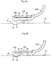
FIG. 5 is a sectional view of an outer joint member in which a radially outer surface is a non-cylindrical, surface. -
FIG. 6 is a front view of the outer joint member illustrated inFIG. 5 . -
FIG. 7 is an enlarged sectional view of main parts of the outer joint member under a state in which the boot is mounted. -
FIG. 8A is a sectional view for illustrating a relationship between a mounting portion of the boot and another boot receiving portion before Mounting the boot. -
FIG. 8B is a sectional view for illustrating a relationship between the portion of the boot and the another boot receiving portion after mounting the boot. -
FIG. 9A is a sectional view for illustrating a relationship between a mounting portion of another boot and a boot receiving portion, of the outer joint member before mounting the another boot. -
FIG. 9B is a sectional view for illustrating a relationship between a mounting portion of another boot and a boot receiving portion of the outer joint member before mounting the another boot. -
FIG. 10 is a sectional view of a drive shaft for which related-art constant velocity universal joints are used. - Now, embodiment of the present invention is described with reference to
FIG. 1 to FIG. 9 .FIG. 1 is an illustration of a drive shaft. The drive shaft comprises a fixed type constant velocity universal, joint 51, a plunging type constant velocity universal, joint 52, and ashaft 50 configured to those constant velocity universal joints. In the illustrated example, a Barfied-type constant velocity universal joint is used as the fixed type constant velocityuniversal joint 51, and a tripod type constant velocity universal joint is used as the plunging type constant velocityuniversal joint 52. - The fixed type constant velocity
universal joint 51 comprises an outerjoint member 55, an innerjoint member 58, a plurality ofballs 59, and acage 60. The outerjoint member 55 includes a radiallyinner surface 54 having a plurality oftracks 53 extending in an axial direction. The innerjoint member 58 includes a radially outer surface 57 having a plurality oftracks 56 extending in the axial direction. The plurality ofballs 59 are interposed between thetracks 53 of the outerjoint member 55 and thetracks 56 of the innerjoint member 58 to transmit a torque. Thecage 60 is interposed between the radiallyinner surface 54 of the outerjoint member 55 and the radially outer surface 57 of the innerjoint member 58 to retain theballs 59. - The plunging type constant velocity
universal joint 52 comprises an outerjoint member 62, atripod member 64, androllers 65. The outerjoint member 62 has threegrooves 61 extending in an axis direction in an inner periphery, androller guide surfaces 61a opposed to each other are formed on inner walls of thegrooves 61. Thetripod member 64 serving as an inner joint member comprises threejournals 63 protruding in a radial direction. Therollers 65 each serving as a torque transmission unit are supported on thejournals 63 so as to be rotatable and are inserted to thegrooves 61 of the outer joint member so as to be rollable. In this case, therollers 65 are externally fitted onto radially outer surfaces of thejournals 63 through intermediation of a plurality ofrollers 66 which are arranged along a circumferential directon. Thetripod member 64 comprises aboss portion 67 and thejournals 63 extending in radial direction from theboss portion 67. - The
shaft 50 hasmale splines shaft 50. Onemale spline 50a is fitted into the innerjoint member 58 of the fixed type constant velocityuniversal joint 51, and anothermale spline 50b is fitted into thetripod member 64 of the plunging type constant velocityuniversal joint 52. Afemale spline 72 is formed in anaxial center hole 71 of the innerjoint member 58, and the onemale spline 50a of theshaft 50 is fitted into theaxial center hole 71 of the innerjoint member 58 and is brought into mesh with thefemale spline 72. Further, the anothermale spline 50b of theshaft 50 is fitted into anaxial center hole 73 of theboss portion 67 of thetripod member 64 and is brought into mesh with afemale spline 74 of theaxial center hole 73. - A
boot 80A configured to seal an opening portion of the outerjoint member 15 is provided to the fixed type constant velocityuniversal joint 51. About 80B configured to seal an opening portion of the outerjoint member 62 is provided to the plunging type constant velocityuniversal joint 52. Each of theboots diameter mounting portion 80a, a small-diameter mounting portion 80b, and a bellows portion 80cwhich constructs a bent portion wich connects the large-diameter mounting portion 80a and the small-diameter mounting portion 80b to each other. The large-diameter mounting portions 80a of theboots fastening clamps boot receiving portions joint members diameter mounting portions 80b of theboots fastening clamps portions 86 and 86) of theshaft 50, respectively. - That is, a boot mounting structure M is formed between the mounting
portion 80a and theboot receiving portion 85 and between the mountingportion 80b and theboot receiving portion 86. First, with reference toFIG. 3 ,FIG. 4A, and FIG. 4B , description is made of the boot mounting structure M on the outerjoint member 55 side on the fixed type constant velocity universal joint 51 side. As illustrated inFIG. 2 , the outerjoint member 55 of the fixed type constant velocityuniversal joint 51 has sixtracks 53 in theinner surface 54. An outer periphery of the outerjoint member 55 has a circular shape. - A
circumferential clamp groove 90 to which thefastening clamp 82A is fitted is formed in an outer peripheral surface of the mountingportion 80a, and a protrudingportion 91 is formed at a boot outer side end portion of an inner peripheral surface of the mountingportion 80a . Further, a recessedportion 92 to which the protrudingportion 91 of the mountingportion 80a is fitted is formed at theboot receiving portion 85 being a cylindrical surface of the outerjoint member 55, and aprojection 93 is formed in the vicinity of the boot inner side of the recessedportion 92. The protrudingportion 91 at the boot outer side end portion and the recessedportion 92 of theboot receiving portion 85 may be formed into an annular shape extending along the circumferential direction or be arranged at predetermined pitches along the circumferential direction. Theprotection 93 may also be formed into an annular shepe extending along the circumferential direction or be arranged at predetermined pitches along the circumferential direction. - In this case, when the large
diameter mounting portion 80 a of theboot 80A is mounted to theboot receiving portion 85 of the outerjoint member 55, the protrudingportion 91 of the large-diameter mounting portion 80a is fitted to the recessedportion 92 of theboot receiving portion 85, to thereby position the large-diameter mounting portion 80a of the boot with respect to theboot receiving portion 85. - Therefore, it is required that a width dimension W, a height dimension H, and the like of the protruding
portion 91 are set to dimensions which enable fitting and positioning of the protrudingportion 91 with respect to the recessedportion 92 of theboot receiving portion 85. When thermoplastic polyester elastomer is employed as a boot material, and the protrudingportion 91 has a fiat semi-elliptical cross-sectionai shape as in the illustrated example, it is preferred that the height dimension H of the protrudingportion 91 be from 20% to 40% of a thickness T of the large-diameter mounting portion 80a of the boot. When the height dimension H is less than 20% of the thickness T, the positioning function is insufficient. When the height dimension H is more than 40% of the thickness T, the mountability is rather degraded. - It: is preferred that the width dimension W of the protruding
portion 91 be from about 3 times to about 15 times, more preferably, from about 5 times to about 10 times larger than the height dimension H of the protrudingportion 91. When the width dimension W is less than 3 times, the protrudingportion 91 has a small volume and thus has a small rigidity, with the result that the positioning function is insufficient in some cases. The width dimension W which is more than 15 times is an unnecessary width, with the result that the compactness is impaired, and the positioning function is rather degraded in some cases. - Further, it is preferred that a position of the protruding
portion 91 partially correspond to a position of theclamp groove 90. In this case, the compactness in the axial direction can further be improved. Through formation of theclamp groove 90, anend surface projection 95 is formed at the radially outer surface end portion of the mountingportion 80a. In this case, the width dimension, the height dimension, and the like of theend surface projection 95 may suitably be set, but the protrudingportion 91 is arranged at a position corresponding to a position of theend surface projection 95. The width dimension of the protrudingportion 91 and the width dimension of theend surface projection 95 may be set equal to each other. However, as described above, in consideration of fastening by thefastening clamp 82A, it is preferred that the position of the protrudingportion 91 partially correspond to the position of theclamp groove 90, - It is only necessary that a width dimension W1 and a depth dimension D of the recessed
portion 92 of theboot receiving portion 85 be set to dimensions required for positioning of theboot 80A. Excessively large dimensions are not desirable because the workability of the outer joint member 55 (shaft 50) and the strength of the outer joint member 55 (shaft 50) are degraded. The width dimension X1 of the recessedportion 92 of theboot receiving portion 85 is set substantially equal to the width dimension W of the protrudingportion 91 along the boot end portion of theboot mounting portion 80a. Further, the depth dimension D of the recessedportion 92 of theboot receiving portion 85 is set equal to or more than 0.8 times, preferably, set substantially equal to the height dimension H of the protrudingportion 91 along the boot end portion of theboot mounting portion 80a, When the depth dimension D is less than 0.8 times, the protrudingportion 91 along the boot end portion of the boot receiving portion is born on a groove bottom of theboot receiving portion 85, with the result, that the mountability and positioning performance of theboot 80A are degraded. When the depth dimension D of the recessedportion 92 of theboot receiving portion 85 is excessively large, the workability of the outerjoint member 55 and the strength of the outerjoint member 55 are degraded. Therefore, it is preferred that the depth, dimension D be equal to or less than one-third of the width dimension W1 of the recessedportion 92. - When a height dimension H1 of the
projection 93 formed on the boot inner side adjacent to the recessedportion 92 of theboot receiving portion 85 is excessively small, the biting amount is small, with the result that the leakage preventing function is insufficient. When the height dimension H1 of theprojection 93 is excessively large, a gap which is formed between the boot receiving portion. 85 and theboot mounting portion 80a is large, and hence the close contact of the cylindrical portions is hindered, with the result that the leakage preventing function is degraded. Therefore, it is preferred that the height dimension H1 of theprojection 93 be equal, to or more than 10% and equal to or less than 35% of the thickness T of theboot mounting portion 80a. Further, when a width dimension W2 of theprojection 93 is excessively large, a close-contact area between the cylindrical portion of theboot receiving portion 85 and the cylindrical inner peripheral surface of the boot mounting portion is reduced, and the close contact is hindered. Therefore, it is preferred that the width dimension W2 of theprojection 93 be equal to or less than 10% of a clamp groove width W3 of theboot mounting portion 80a. - It is intended that the cylindrical portion of the
boot receiving portion 85 and the cylindrical inner peripheral surface of theboot mounting portion 80a be brought into close contact with each other through fastening by thefastening clamp 82A. The close-contact area is kept large to receive a twisting force in a circumferential direction, a force in the axial direction, and a force of vertical movement, which are caused by deformation of the boot bellowsportion 80c when the constant velocity universel joint takes the operating angle or rotates while sliding, thereby suppressing deformation of theboot mounting portion 80a. Therefors, in order to secure a sufficient close-contact area, the annular projection of theboot receiving portion 85 is formed at a position closer to the boot outer side with respect to a center of theclamp groove 90 of theboot mounting portion 80a and thefastening clamp 82A. - This means that the axial length along which the cylindrical portion of the
boot receiving portion 85 and the cylindrical inner peripheral surface of theboot mounting portion 80a are in close contact with each other is equal to or more than 50% of the clamp groove width in the outer periphery of the boot receiving portion and a width W4 of thefastening clamp 82A. More preferably, the axial length of equal to or more than 65% is secured, It is preferred that the width W4 of thefastening clamp 82A have a dimension substantially equal to the clamp groove width W3 of theboot mounting portion 80a or be equal to or more than 90% of the clamp groove width. - It is preferred that the boot material, be thermoplastic polyester elastomer having a type-D durometer hardness, which is based on JIS K6253, of equal to or more than 35 and equal to or less than 55(from 35 to 55). When a material having a hardness of less than 35 is employed, the thermal resistance and the rotational expansion performance of the boot are degraded. When a material having a hardness of more than 55 is employed, the fatigability and the wearability are degraded. As a result, the performance required for the boot is not satisfied.
- Also on the small-
diameter mounting portion 80b side of theboot 80A for the fixed type constant velocityuniversal joint 51, thecircumferential clamp groove 90 to which thefastening clamp 83A is fitted is formed in the outer peripheral surface of the mountingportion 80b, and the protrudingportion 91 is formed at the boot outer side end portion of the inner peripheral surface of the mountingportion 80b. Further, the recessedportion 92 to which the protrudingportion 91 of the mountingportion 80b is fitted is formed in theboot receiving portion 86 being the cylindrical surface of theshaft 50, and theprojection 93 is formed in the vicinity of the boot inner side of the recessedportion 92. - As illustrated in
FIG. 5 to FIG. 7 , thecircumferential clamp groove 90 to which thefastening clamp 82B is fitted is formed in the outer peripheral surface of the mountingportion 80a of theboot 80B for the plunging type constant velocityuniversal joint 52, and the protrudingportion 91 is formed at the boot outer side end portion of the inner peripheral surface of the mountingportion 80a. Further, the recessedportion 92 to which the protrudingportion 91 of the mountingportion 80a is fitted is formed in theboot receiving portion 85 being the cylindrical surface of the outerjoint member 62, and theprojection 93 is formed in the vicinity of the boot inner side of the recessedportion 92. - Also on the small-
diameter mounting portion 80b side of theboot 80B for the plunging type constant velocityuniversal joint 52, thecircumferential clamp groove 90 to which thefastening clamp 83B is fitted is formed in the outer peripheral surface of the mountingportion 80b, and the protrudingportion 91 is formed at the boot outer side end portion of the inner peripheral surface of the mountingportion 80b. Further, the recessedportion 92 to which the protrudingportion 91 of the mountingportion 80b is fitted is formed in theboot receiving portion 86 being the cylindrical surface of theshaft 50, and theprojection 93 is formed in the vicinity of the boot inner side of the recessedportion 92. - Through use of such a boot mounting structure, when the
fastening clamp 82A (82B, 83A, or 83B) which is fitted to theclamp groove 90 is fastened, theprojection 93 of the boot receiving portion 85 (86) bites into a part of the cylindrical inner peripheral surface of theboot mounting portion 80a (80b), and the cylindrical inner peripheral surface of theboot mounting portion 80a (80b) is brought into close contact with the cylindrical surface of the boot receiving portion 85 (86). A sufficient close-contact area of the cylindrical inner peripheral surface is secured, and hence, even when the twisting force in the circumferential direction, the force in the axial direction, and the force of vertical movement, which are caused by deformation of the boot bellowsportion 80c when the constant velocity universal joint rotates while taking the operating angle or sliding, are repeatedly received, the cylindrical portion of theboot mounting portion 80a (80b) is firmly fixed, thereby being capable of suppressing the deformation of theboot mounting portion 80a (80b). - Further, the portion of the
boot mounting portion 80a (80b) which is bitten by theprojection 93 of the boot clamp receiving portion 85 (86) is firmly fixed by thefastening clamp 82A (82B, 83A, or 83B), and the force caused by the repeated deformation of the boot bellowsportion 80c is hardly transmitted. Therefore, deformation of theboot mounting portion 80a (80b) is suppressed, thereby being capable of suppressing reduction in the biting force. As a result, a minute gap formed between the boot receiving portion 85 (86) and theboot mounting portion 80a (80b) can be minimized, and the relative movement of the boot receiving portion 85 (86) and theboot mounting portion 80a (80b) can be reduced, thereby being capable of preventing entry of lubricant (grease), which is sealed in the constant velocity universal joint, into the gap. A small amount of the lubricant which enters the gap even with the above-mentioned configuration is completely prevented from leaking to the outside because theprojection 93 formed on the boot receiving portion 85 (86) stably bites into the inner periphery of the boot mounting portion. - As illustrated in
FIG. 6 , the outerjoint member 62 of the plunging type constant velocity universal joint 52 illustrated inFIG. 5 comprises large-diameter portions 52a, which correspond to groove bottoms of thegrooves 61, and small-diameter portions 52b each located between theadjacent grooves 61. Therefore, the outerjoint member 62 has a non-cylindrical surface shape. In this case, the radially surfaces of the large-diameter portions 52a are cylindrical surfaces. - Therefore, as illustrated in
FIG. 6 , the large-diameter mounting portion 80a of theboot 80B comprises large-thickness portions 96 and small-thickness portions 97. Therefore, the protrudingportion 91 is formed on the radially inner surface of each small-thickness portion 97, and the recessedportion 92 and theprojection 93 of the outerjoint member 55 are formed on the radially outer surface of the large-diameter portion 52a. Further, together with the formation of the recessedportion 92 andprojection 93, the protrudingportion 91 may be formed on the radially inner surface of the large-thickness portion 96, and the recessedportion 92 and theprojection 93 of outerjoint member 55 may be formed on the radially outer surface of the small-diameter portion 52b. - In
FIG. 8A and FIG. 8B , theprojection 93 of theboot receiving portion 86 is located further on the boot inner side as compared to the above-mentioned embodiment. Theprojection 93 is located at a position within the range which is capable of securing a sufficient close-contact area between the cylindrical surface of theboot receiving portion 86 and the cylindrical surface of theboot mounting portion 80b, stably fixing the cylindrical portion of the mountingportion 80b of theboot 80B, and suppressing the deformation of theboot mounting portion 80b. - Further, in
FIG. 9A , asmall projection 98 is formed on the radially inner surface of the mountingportion 80b of theboot 80B. Similarly to theprojection 93, thesmall projection 98 is located at a position within the range which is capable of securing a sufficient, close-contact area between the cylindrical surface of theboot receiving portion 86 and the cylindrical surface of theboot mounting portion 80b. Therefore, as illustrated inFIG. 9B , a plurality ofsmall projections 98 may be formed along the axial direction. When thesmall projection 98 is formed, it is preferred that a height dimension of thesmall projection 98 be smaller than the height dimension of the protrudingportion 91. When the height dimension of thesmall projection 98 is larger than the height dimension of the protrudingportion 91, there is possibility that the positioning function through fitting of the protrudingportion 91 to the recessedportion 92 cannot be achieved. - In the above, description is made of the embodiment of the present invention. However, the present invention is not limited to the above-mentioned embodiment, and various modification may be made. In the above-mentioned embodiment, the protruding
portion 91 has a flat semi-elliptical cross-sectional shape. However, the cross-sectional shape of the protrudingportion 91 is not limited thereto, and may be a semi-circular shape, a semi-polygonal shape a rectangular shape, or the like. Therefore, a cross-sectional shape of the recessedportion 92 to which the protrudingportion 91 is fitted may be a semi-circular shape, a semi-polygonal shape, a rectangular shape, or the like. Further, in the above-mentioned embodiment, theprojection 93 has a cross-sectional shape of like (like a flat chevron mark) shape, which is a cross-sectional shape having a trapezoidal shape in which both sides form a gently curved recessed surface on the bottom side. However, the cross-sectional shape of theprojection 93 is not limited thereto, and may be a trapezoidal shape or the like. When the plurality ofsmall projections 98 are formed as illustrated, inFIG. 9B , the number, arrangement pitch, and the like of thesmall projections 98 may be suitably set. - The boot mounting structure M illustrated in
FIGS. 8 andFIGS. 9 is provided on the small-diameter mounting portion 80b side of theboot 80B for the plunging type constant velocityuniversal joint 52. However, the boot mounting structure M may be used for the large-diameter mounting portion 80a side of theboot 80B, and may further be used for the large-diameter mounting portion 80a side and the small-diameter mounting portion 80b side of theboot 80A for the fixed type constant velocity universal joint. - Further, in the above-mentioned embodiment, the boot mounting structure M on each of the large-diameter side and the small-diameter side of the boot for each of the fixed type constant velocity universal joint and the plunging type constant velocity universal joint has the configuration of the present invention, which comprises the protruding
portion 91 formed on the inner peripheral surface of the mountingportion 80a (80b), the recessedportion 92 formed in the boot receiving portion 85 (86), and theprojection 93 formed in the vicinity of the recessedportion 92. However, it is only necessary that the boot mounting structure M be provided on any one of the large-diameter side and the small-diameter side. - The fixed type constant velocity universal joint may be a Barfield-type constant velocity universal joint or an undercut-free constant velocity universal joint, and the plunging type constant velocity universal joint may be a tripod type constant velocity universal joint, a double-offset constant velocity universal joint, or a cross-groove constant velocity universal joint. The constant velocity universal joint may be used for a propeller shaft other than the drive shaft. Further, when the tripod type constant velocity universal joint is used as the plunging type constant velocity universal joint, a single roller type or a double roller type may be used.
-
- 55, 62
- outer joint member
- 58
- inner joint member
- 59
- ball
- 64
- tripod member
- 65
- roller
- 80A, 80B
- boot
- 80b
- mounting portion
- 80c
- bellows portion
- 82A, 82B, 83A, 83B
- fastening clamp
- 85, 86
- boot receiving portion
- 90
- circumferential clamp groove
- 91
- protruding portion
- 92
- recessed portion
- 93
- projection
Claims (6)
- A constant velocity universal joint, comprising:an outer joint member;an inner joint member; anda torque transmission member which is interposed between the outer joint member and the inner joint member,the outer joint member having an opening portion sealed with a boot,the boot comprising:a large-diameter mounting portion which is mounted to a boot receiving portion formed on a radially outer surface of the outer joint member on an opening portion side;a small-diameter mounting portion which is mounted to a boot receiving portion on a shaft fitted to the inner joint member; anda bent portion which connects the large-diameter mounting portion and the small-diameter mounting portion to each other,the large-diameter mounting portion being fastened and fixed by a fastening clamp in a state of being externally fitted onto the boot receiving portion of the outer joint member,the small-diameter mounting portion being fastened and fixed by a fastening clamp in a state of being externally fitted onto a boot receiving ion of the shaft,the large-diameter mounting portion comprising:a circumferential clamp groove to which the fastening clamp is fitted, the circumferential clamp groove being formed in an outer peripheral surface of the large-diameter mounting portion anda protruding portion formed on a boot outer side end portion of the inner peripheral surface of the large-diameter mounting portion,the boot receiving portion being a cylindrical surface of the outer joint member comprising:a recessed portion to which the protruding portion of the large-diameter mounting portion is fitted; anda projection formed in a vicinity of a boot inner side of the recessed portion.
- A constant velocity universal joint, comprising:an outer joint member;an inner joint member; anda torque transmission member which is interposed between the outer joint member and the inner joint member,the outer joint member having an opening portion sealed with a boot,the boot comprising:a large-diameter mounting portion which is mounted to a boot receiving portion formed on a radially outer surface of the outer joint member on an opening portion side;a small-diameter mounting portion which is mounted to a boot receiving portion on a shaft fitted to the inner joint member; anda bent portion which connects the large-diameter mounting portion and the small-diameter mounting portion to each other,the large-diameter mounting portion being fastened and fixed by a fastening clamp in a state of being externally fitted onto the boot receiving portion of the outer joint member,the small-diameter mounting portion being fastened and fixed by a fastening clamp in a state of being externally fitted onto a boot receiving portion of the shaft,the small-diameter mounting portion comprising:a circumferential clamp groove to which the fastening clamp is fitted, the circumferential clamp groove being formed in an outer peripheral surface of the small-diameter mounting portion; anda protruding portion formed on a boot outer side end portion of the inner peripheral surface of the small-diameter mounting portion,the boot receiving portion being a cylindrical surface of the shaft comprising:a recessed portion to which the protruding portion of the small-diameter mounting portion is fitted; anda projection formed in a vicinity of a boot inner side of the recessed portion.
- The constant velocity universal joint according to claim 1 or 2, wherein the projection is opposed to the circumferential clamp groove and is positioned on a boot outer side from a center of the circumferential clamp groove in a width direction of the circumferential clamp groove.
- The constant velocity universal joint according to any one of claims 1 to 3,
wherein a height dimension of the protruding portion of the boot is set to a dimension which causes the protruding portion to be brought into close contact or into contact with the recessed portion to which the protruding portion is fitted, and
wherein a cylindrical surface of the mounting portion of the boot, which is fitted to the boot receiving portion, is fitted with an interference to the cylindrical surface of the boot receiving portion, and fastening by the fastening clamp causes the projection of the boot receiving portion to bite into the mounting portion of the boot having the cylindrical surface shape from a radially inner side of the boot, to thereby cause the boot receiving portion having the cylindrical surface and the mounting portion of the boot having the cylindrical surface shape to be fixed in close contact with each other. - The constant velocity universal joint according to any one of claims 1 to 4,
wherein a height of the projection of the boot receiving portion is set equal to or more than 10% and equal to or less than 35% of a thickness of the mounting portion which is mounted to the boot receiving portion,
wherein a width dimension of the projection is set equal to or less than 10% of a width dimension of the clamp groove, and
wherein an axial length of a close-contact fixing portion between the cylindrical surface of the boot receiving portion and the cylindrical surface of the mounting portion of the boot is set equal to or more than 65% of the width dimension of the clamp groove. - The constant velocity universal joint according to any one of claims 1 to 5, wherein a boot material is thermoplastic polyester elastomer having a type-D durometer hardness, which is defined by JIS K6253, of equal to or more than 35 and equal to or less than 55.
Applications Claiming Priority (2)
| Application Number | Priority Date | Filing Date | Title |
|---|---|---|---|
| JP2015035463A JP6517042B2 (en) | 2015-02-25 | 2015-02-25 | Constant velocity universal joint |
| PCT/JP2016/052060 WO2016136355A1 (en) | 2015-02-25 | 2016-01-26 | Constant velocity universal joint |
Publications (3)
| Publication Number | Publication Date |
|---|---|
| EP3263939A1 true EP3263939A1 (en) | 2018-01-03 |
| EP3263939A4 EP3263939A4 (en) | 2018-09-05 |
| EP3263939B1 EP3263939B1 (en) | 2019-09-25 |
Family
ID=56789274
Family Applications (1)
| Application Number | Title | Priority Date | Filing Date |
|---|---|---|---|
| EP16755105.0A Active EP3263939B1 (en) | 2015-02-25 | 2016-01-26 | Constant velocity universal joint |
Country Status (5)
| Country | Link |
|---|---|
| US (1) | US10550894B2 (en) |
| EP (1) | EP3263939B1 (en) |
| JP (1) | JP6517042B2 (en) |
| CN (1) | CN107250588B (en) |
| WO (1) | WO2016136355A1 (en) |
Families Citing this family (3)
| Publication number | Priority date | Publication date | Assignee | Title |
|---|---|---|---|---|
| JP7177252B2 (en) * | 2018-09-28 | 2022-11-22 | コンティネンタル・テーベス・アクチエンゲゼルシヤフト・ウント・コンパニー・オッフェネ・ハンデルスゲゼルシヤフト | Improved flexible dust boot for automotive brake cylinders |
| CN110259840A (en) * | 2019-06-13 | 2019-09-20 | 奇瑞汽车股份有限公司 | Internal spherical cage assembling structure |
| WO2021029228A1 (en) * | 2019-08-14 | 2021-02-18 | 日立オートモティブシステムズ株式会社 | Propeller shaft and production method therefor |
Family Cites Families (19)
| Publication number | Priority date | Publication date | Assignee | Title |
|---|---|---|---|---|
| JPH0710562A (en) | 1993-06-21 | 1995-01-13 | Canon Inc | Die for molding optical device |
| JP2598536Y2 (en) * | 1993-07-23 | 1999-08-16 | エヌティエヌ株式会社 | Constant velocity universal joint boot mounting structure |
| JP2942709B2 (en) * | 1994-11-24 | 1999-08-30 | 本田技研工業株式会社 | Rotary joint boot mounting structure |
| JP3964944B2 (en) | 1995-12-27 | 2007-08-22 | Ntn株式会社 | Boot mounting structure |
| US6244967B1 (en) * | 1997-09-30 | 2001-06-12 | Ntn Corporation | Constant velocity joint with resin boot |
| FR2796686B1 (en) * | 1999-07-19 | 2001-12-07 | Gkn Glaenzer Spicer | BELLOWS AND CORRESPONDING TRANSMISSION JOINT |
| JP2003113858A (en) * | 2001-10-04 | 2003-04-18 | Toyoda Gosei Co Ltd | Boot for constant velocity universal joint |
| JP4359532B2 (en) * | 2003-09-02 | 2009-11-04 | 株式会社フコク | Method for manufacturing constant velocity joint boot and manufacturing apparatus used in the method |
| US7347787B2 (en) * | 2004-11-24 | 2008-03-25 | Toyo Tire & Rubber Co., Ltd. | Joint boot |
| JP4532440B2 (en) * | 2004-11-24 | 2010-08-25 | 東洋ゴム工業株式会社 | Joint boots |
| CN100582512C (en) * | 2005-01-20 | 2010-01-20 | 富国股份有限公司 | Hood for constant velocity cardan joint |
| EP1890047A4 (en) * | 2005-05-16 | 2010-07-07 | Honda Motor Co Ltd | Rotation drive force transmission mechanism, constant velocity universal joint and resin joint boot constructing the mechanism, and method of tightening clamp band for constant velocity universal joint |
| JP4657897B2 (en) | 2005-11-28 | 2011-03-23 | Ntn株式会社 | Seal structure |
| JP2007146960A (en) | 2005-11-28 | 2007-06-14 | Ntn Corp | Sealing structure |
| JP2007155003A (en) | 2005-12-05 | 2007-06-21 | Ntn Corp | Constant velocity universal joint boot |
| DE102006008558B3 (en) * | 2006-02-22 | 2007-08-02 | Gkn Driveline International Gmbh | Bellows arrangement for tripod joint unit, uses adapter ring matched to outer shape of outer part of joint |
| JP2007232144A (en) | 2006-03-02 | 2007-09-13 | Ntn Corp | Shaft for constant velocity universal joint |
| JP2008045675A (en) | 2006-08-17 | 2008-02-28 | Ntn Corp | Boot mounting structure of constant velocity universal joint |
| JP2013087885A (en) * | 2011-10-19 | 2013-05-13 | Ntn Corp | Constant velocity universal joint |
-
2015
- 2015-02-25 JP JP2015035463A patent/JP6517042B2/en not_active Expired - Fee Related
-
2016
- 2016-01-26 US US15/551,379 patent/US10550894B2/en not_active Expired - Fee Related
- 2016-01-26 WO PCT/JP2016/052060 patent/WO2016136355A1/en active Application Filing
- 2016-01-26 EP EP16755105.0A patent/EP3263939B1/en active Active
- 2016-01-26 CN CN201680011726.2A patent/CN107250588B/en not_active Expired - Fee Related
Also Published As
| Publication number | Publication date |
|---|---|
| EP3263939B1 (en) | 2019-09-25 |
| CN107250588A (en) | 2017-10-13 |
| WO2016136355A1 (en) | 2016-09-01 |
| JP2016156469A (en) | 2016-09-01 |
| EP3263939A4 (en) | 2018-09-05 |
| US20180031047A1 (en) | 2018-02-01 |
| US10550894B2 (en) | 2020-02-04 |
| CN107250588B (en) | 2020-01-21 |
| JP6517042B2 (en) | 2019-05-22 |
Similar Documents
| Publication | Publication Date | Title |
|---|---|---|
| US8328650B2 (en) | Constant velocity universal joint | |
| EP3263939B1 (en) | Constant velocity universal joint | |
| US8337111B2 (en) | Axial retention assembly | |
| US20110018212A1 (en) | Silicone boot for constant velocity universal joint and constant velocity universal joint | |
| WO2016152667A1 (en) | Sliding constant velocity universal joint | |
| US11525484B2 (en) | Constant velocity universal joint | |
| JP2009228727A (en) | Dust preventing device for joint | |
| US11047425B2 (en) | Stationary constant-velocity universal joint | |
| JP2010106942A (en) | Double offset type constant velocity universal joint | |
| JP2006312953A (en) | Fixed type constant velocity universal joint | |
| US11073179B2 (en) | Sliding-type constant velocity universal joint and method for manufacturing same | |
| JP2010261532A (en) | Constant velocity universal coupling | |
| EP3351808A1 (en) | Boot band | |
| JP2010001979A (en) | Constant velocity universal joint | |
| JP2006348990A (en) | Boot | |
| JP2023020379A (en) | constant velocity universal joint | |
| JP2020034063A (en) | Constant velocity universal joint | |
| JP2007155098A (en) | Boot for constant velocity universal joint, and its assembling method | |
| JP2007032643A (en) | Flexible boots for constant velocity universal joint | |
| JP2006275170A (en) | Fixed type constant velocity universal joint | |
| JP2008038959A (en) | Shaft coming-off preventive structure | |
| JP2017110694A (en) | Contact velocity universal joint | |
| JP2017155907A (en) | Constant velocity universal joint | |
| JP2004316922A (en) | Rolling bearing unit for wheel | |
| JP2015068377A (en) | Constant velocity universal joint |
Legal Events
| Date | Code | Title | Description |
|---|---|---|---|
| STAA | Information on the status of an ep patent application or granted ep patent |
Free format text: STATUS: THE INTERNATIONAL PUBLICATION HAS BEEN MADE |
|
| PUAI | Public reference made under article 153(3) epc to a published international application that has entered the european phase |
Free format text: ORIGINAL CODE: 0009012 |
|
| STAA | Information on the status of an ep patent application or granted ep patent |
Free format text: STATUS: REQUEST FOR EXAMINATION WAS MADE |
|
| 17P | Request for examination filed |
Effective date: 20170829 |
|
| AK | Designated contracting states |
Kind code of ref document: A1 Designated state(s): AL AT BE BG CH CY CZ DE DK EE ES FI FR GB GR HR HU IE IS IT LI LT LU LV MC MK MT NL NO PL PT RO RS SE SI SK SM TR |
|
| AX | Request for extension of the european patent |
Extension state: BA ME |
|
| DAV | Request for validation of the european patent (deleted) | ||
| DAX | Request for extension of the european patent (deleted) | ||
| A4 | Supplementary search report drawn up and despatched |
Effective date: 20180807 |
|
| RIC1 | Information provided on ipc code assigned before grant |
Ipc: F16J 3/04 20060101ALI20180801BHEP Ipc: C23C 18/00 20060101ALI20180801BHEP Ipc: C25D 5/00 20060101ALI20180801BHEP Ipc: F16J 15/52 20060101ALI20180801BHEP Ipc: F16D 3/84 20060101AFI20180801BHEP Ipc: F16D 3/24 20060101ALI20180801BHEP Ipc: C25D 3/00 20060101ALI20180801BHEP |
|
| RIC1 | Information provided on ipc code assigned before grant |
Ipc: C23C 18/00 20060101ALI20190326BHEP Ipc: F16J 3/04 20060101ALI20190326BHEP Ipc: F16D 3/84 20060101AFI20190326BHEP Ipc: C25D 3/00 20060101ALI20190326BHEP Ipc: F16J 15/52 20060101ALI20190326BHEP Ipc: F16D 3/223 20110101ALI20190326BHEP Ipc: F16D 3/24 20060101ALI20190326BHEP Ipc: C25D 5/00 20060101ALI20190326BHEP Ipc: F16D 3/205 20060101ALI20190326BHEP |
|
| GRAP | Despatch of communication of intention to grant a patent |
Free format text: ORIGINAL CODE: EPIDOSNIGR1 |
|
| STAA | Information on the status of an ep patent application or granted ep patent |
Free format text: STATUS: GRANT OF PATENT IS INTENDED |
|
| INTG | Intention to grant announced |
Effective date: 20190517 |
|
| GRAS | Grant fee paid |
Free format text: ORIGINAL CODE: EPIDOSNIGR3 |
|
| GRAA | (expected) grant |
Free format text: ORIGINAL CODE: 0009210 |
|
| STAA | Information on the status of an ep patent application or granted ep patent |
Free format text: STATUS: THE PATENT HAS BEEN GRANTED |
|
| AK | Designated contracting states |
Kind code of ref document: B1 Designated state(s): AL AT BE BG CH CY CZ DE DK EE ES FI FR GB GR HR HU IE IS IT LI LT LU LV MC MK MT NL NO PL PT RO RS SE SI SK SM TR |
|
| REG | Reference to a national code |
Ref country code: GB Ref legal event code: FG4D |
|
| REG | Reference to a national code |
Ref country code: CH Ref legal event code: EP |
|
| REG | Reference to a national code |
Ref country code: AT Ref legal event code: REF Ref document number: 1184104 Country of ref document: AT Kind code of ref document: T Effective date: 20191015 |
|
| REG | Reference to a national code |
Ref country code: IE Ref legal event code: FG4D |
|
| REG | Reference to a national code |
Ref country code: DE Ref legal event code: R096 Ref document number: 602016021295 Country of ref document: DE |
|
| REG | Reference to a national code |
Ref country code: NL Ref legal event code: MP Effective date: 20190925 |
|
| PG25 | Lapsed in a contracting state [announced via postgrant information from national office to epo] |
Ref country code: BG Free format text: LAPSE BECAUSE OF FAILURE TO SUBMIT A TRANSLATION OF THE DESCRIPTION OR TO PAY THE FEE WITHIN THE PRESCRIBED TIME-LIMIT Effective date: 20191225 Ref country code: LT Free format text: LAPSE BECAUSE OF FAILURE TO SUBMIT A TRANSLATION OF THE DESCRIPTION OR TO PAY THE FEE WITHIN THE PRESCRIBED TIME-LIMIT Effective date: 20190925 Ref country code: FI Free format text: LAPSE BECAUSE OF FAILURE TO SUBMIT A TRANSLATION OF THE DESCRIPTION OR TO PAY THE FEE WITHIN THE PRESCRIBED TIME-LIMIT Effective date: 20190925 Ref country code: SE Free format text: LAPSE BECAUSE OF FAILURE TO SUBMIT A TRANSLATION OF THE DESCRIPTION OR TO PAY THE FEE WITHIN THE PRESCRIBED TIME-LIMIT Effective date: 20190925 Ref country code: HR Free format text: LAPSE BECAUSE OF FAILURE TO SUBMIT A TRANSLATION OF THE DESCRIPTION OR TO PAY THE FEE WITHIN THE PRESCRIBED TIME-LIMIT Effective date: 20190925 Ref country code: NO Free format text: LAPSE BECAUSE OF FAILURE TO SUBMIT A TRANSLATION OF THE DESCRIPTION OR TO PAY THE FEE WITHIN THE PRESCRIBED TIME-LIMIT Effective date: 20191225 |
|
| REG | Reference to a national code |
Ref country code: LT Ref legal event code: MG4D |
|
| PG25 | Lapsed in a contracting state [announced via postgrant information from national office to epo] |
Ref country code: RS Free format text: LAPSE BECAUSE OF FAILURE TO SUBMIT A TRANSLATION OF THE DESCRIPTION OR TO PAY THE FEE WITHIN THE PRESCRIBED TIME-LIMIT Effective date: 20190925 Ref country code: LV Free format text: LAPSE BECAUSE OF FAILURE TO SUBMIT A TRANSLATION OF THE DESCRIPTION OR TO PAY THE FEE WITHIN THE PRESCRIBED TIME-LIMIT Effective date: 20190925 Ref country code: GR Free format text: LAPSE BECAUSE OF FAILURE TO SUBMIT A TRANSLATION OF THE DESCRIPTION OR TO PAY THE FEE WITHIN THE PRESCRIBED TIME-LIMIT Effective date: 20191226 |
|
| REG | Reference to a national code |
Ref country code: AT Ref legal event code: MK05 Ref document number: 1184104 Country of ref document: AT Kind code of ref document: T Effective date: 20190925 |
|
| PG25 | Lapsed in a contracting state [announced via postgrant information from national office to epo] |
Ref country code: AT Free format text: LAPSE BECAUSE OF FAILURE TO SUBMIT A TRANSLATION OF THE DESCRIPTION OR TO PAY THE FEE WITHIN THE PRESCRIBED TIME-LIMIT Effective date: 20190925 Ref country code: IT Free format text: LAPSE BECAUSE OF FAILURE TO SUBMIT A TRANSLATION OF THE DESCRIPTION OR TO PAY THE FEE WITHIN THE PRESCRIBED TIME-LIMIT Effective date: 20190925 Ref country code: NL Free format text: LAPSE BECAUSE OF FAILURE TO SUBMIT A TRANSLATION OF THE DESCRIPTION OR TO PAY THE FEE WITHIN THE PRESCRIBED TIME-LIMIT Effective date: 20190925 Ref country code: PL Free format text: LAPSE BECAUSE OF FAILURE TO SUBMIT A TRANSLATION OF THE DESCRIPTION OR TO PAY THE FEE WITHIN THE PRESCRIBED TIME-LIMIT Effective date: 20190925 Ref country code: EE Free format text: LAPSE BECAUSE OF FAILURE TO SUBMIT A TRANSLATION OF THE DESCRIPTION OR TO PAY THE FEE WITHIN THE PRESCRIBED TIME-LIMIT Effective date: 20190925 Ref country code: ES Free format text: LAPSE BECAUSE OF FAILURE TO SUBMIT A TRANSLATION OF THE DESCRIPTION OR TO PAY THE FEE WITHIN THE PRESCRIBED TIME-LIMIT Effective date: 20190925 Ref country code: RO Free format text: LAPSE BECAUSE OF FAILURE TO SUBMIT A TRANSLATION OF THE DESCRIPTION OR TO PAY THE FEE WITHIN THE PRESCRIBED TIME-LIMIT Effective date: 20190925 Ref country code: AL Free format text: LAPSE BECAUSE OF FAILURE TO SUBMIT A TRANSLATION OF THE DESCRIPTION OR TO PAY THE FEE WITHIN THE PRESCRIBED TIME-LIMIT Effective date: 20190925 Ref country code: PT Free format text: LAPSE BECAUSE OF FAILURE TO SUBMIT A TRANSLATION OF THE DESCRIPTION OR TO PAY THE FEE WITHIN THE PRESCRIBED TIME-LIMIT Effective date: 20200127 |
|
| PGFP | Annual fee paid to national office [announced via postgrant information from national office to epo] |
Ref country code: DE Payment date: 20200127 Year of fee payment: 5 |
|
| PG25 | Lapsed in a contracting state [announced via postgrant information from national office to epo] |
Ref country code: IS Free format text: LAPSE BECAUSE OF FAILURE TO SUBMIT A TRANSLATION OF THE DESCRIPTION OR TO PAY THE FEE WITHIN THE PRESCRIBED TIME-LIMIT Effective date: 20200224 Ref country code: SK Free format text: LAPSE BECAUSE OF FAILURE TO SUBMIT A TRANSLATION OF THE DESCRIPTION OR TO PAY THE FEE WITHIN THE PRESCRIBED TIME-LIMIT Effective date: 20190925 Ref country code: SM Free format text: LAPSE BECAUSE OF FAILURE TO SUBMIT A TRANSLATION OF THE DESCRIPTION OR TO PAY THE FEE WITHIN THE PRESCRIBED TIME-LIMIT Effective date: 20190925 Ref country code: CZ Free format text: LAPSE BECAUSE OF FAILURE TO SUBMIT A TRANSLATION OF THE DESCRIPTION OR TO PAY THE FEE WITHIN THE PRESCRIBED TIME-LIMIT Effective date: 20190925 |
|
| REG | Reference to a national code |
Ref country code: DE Ref legal event code: R097 Ref document number: 602016021295 Country of ref document: DE |
|
| PGFP | Annual fee paid to national office [announced via postgrant information from national office to epo] |
Ref country code: FR Payment date: 20200128 Year of fee payment: 5 |
|
| PG2D | Information on lapse in contracting state deleted |
Ref country code: IS |
|
| PG25 | Lapsed in a contracting state [announced via postgrant information from national office to epo] |
Ref country code: IS Free format text: LAPSE BECAUSE OF FAILURE TO SUBMIT A TRANSLATION OF THE DESCRIPTION OR TO PAY THE FEE WITHIN THE PRESCRIBED TIME-LIMIT Effective date: 20200126 Ref country code: DK Free format text: LAPSE BECAUSE OF FAILURE TO SUBMIT A TRANSLATION OF THE DESCRIPTION OR TO PAY THE FEE WITHIN THE PRESCRIBED TIME-LIMIT Effective date: 20190925 |
|
| PLBE | No opposition filed within time limit |
Free format text: ORIGINAL CODE: 0009261 |
|
| STAA | Information on the status of an ep patent application or granted ep patent |
Free format text: STATUS: NO OPPOSITION FILED WITHIN TIME LIMIT |
|
| PG25 | Lapsed in a contracting state [announced via postgrant information from national office to epo] |
Ref country code: MC Free format text: LAPSE BECAUSE OF FAILURE TO SUBMIT A TRANSLATION OF THE DESCRIPTION OR TO PAY THE FEE WITHIN THE PRESCRIBED TIME-LIMIT Effective date: 20190925 |
|
| REG | Reference to a national code |
Ref country code: CH Ref legal event code: PL |
|
| 26N | No opposition filed |
Effective date: 20200626 |
|
| GBPC | Gb: european patent ceased through non-payment of renewal fee |
Effective date: 20200126 |
|
| REG | Reference to a national code |
Ref country code: BE Ref legal event code: MM Effective date: 20200131 |
|
| PG25 | Lapsed in a contracting state [announced via postgrant information from national office to epo] |
Ref country code: GB Free format text: LAPSE BECAUSE OF NON-PAYMENT OF DUE FEES Effective date: 20200126 Ref country code: LU Free format text: LAPSE BECAUSE OF NON-PAYMENT OF DUE FEES Effective date: 20200126 |
|
| PG25 | Lapsed in a contracting state [announced via postgrant information from national office to epo] |
Ref country code: CH Free format text: LAPSE BECAUSE OF NON-PAYMENT OF DUE FEES Effective date: 20200131 Ref country code: BE Free format text: LAPSE BECAUSE OF NON-PAYMENT OF DUE FEES Effective date: 20200131 Ref country code: SI Free format text: LAPSE BECAUSE OF FAILURE TO SUBMIT A TRANSLATION OF THE DESCRIPTION OR TO PAY THE FEE WITHIN THE PRESCRIBED TIME-LIMIT Effective date: 20190925 Ref country code: LI Free format text: LAPSE BECAUSE OF NON-PAYMENT OF DUE FEES Effective date: 20200131 |
|
| PG25 | Lapsed in a contracting state [announced via postgrant information from national office to epo] |
Ref country code: IE Free format text: LAPSE BECAUSE OF NON-PAYMENT OF DUE FEES Effective date: 20200126 |
|
| REG | Reference to a national code |
Ref country code: DE Ref legal event code: R119 Ref document number: 602016021295 Country of ref document: DE |
|
| PG25 | Lapsed in a contracting state [announced via postgrant information from national office to epo] |
Ref country code: FR Free format text: LAPSE BECAUSE OF NON-PAYMENT OF DUE FEES Effective date: 20210131 |
|
| PG25 | Lapsed in a contracting state [announced via postgrant information from national office to epo] |
Ref country code: DE Free format text: LAPSE BECAUSE OF NON-PAYMENT OF DUE FEES Effective date: 20210803 |
|
| PG25 | Lapsed in a contracting state [announced via postgrant information from national office to epo] |
Ref country code: TR Free format text: LAPSE BECAUSE OF FAILURE TO SUBMIT A TRANSLATION OF THE DESCRIPTION OR TO PAY THE FEE WITHIN THE PRESCRIBED TIME-LIMIT Effective date: 20190925 Ref country code: MT Free format text: LAPSE BECAUSE OF FAILURE TO SUBMIT A TRANSLATION OF THE DESCRIPTION OR TO PAY THE FEE WITHIN THE PRESCRIBED TIME-LIMIT Effective date: 20190925 Ref country code: CY Free format text: LAPSE BECAUSE OF FAILURE TO SUBMIT A TRANSLATION OF THE DESCRIPTION OR TO PAY THE FEE WITHIN THE PRESCRIBED TIME-LIMIT Effective date: 20190925 |
|
| PG25 | Lapsed in a contracting state [announced via postgrant information from national office to epo] |
Ref country code: MK Free format text: LAPSE BECAUSE OF FAILURE TO SUBMIT A TRANSLATION OF THE DESCRIPTION OR TO PAY THE FEE WITHIN THE PRESCRIBED TIME-LIMIT Effective date: 20190925 |