EP3263847A1 - Rankine cycle system - Google Patents
Rankine cycle system Download PDFInfo
- Publication number
- EP3263847A1 EP3263847A1 EP16755363.5A EP16755363A EP3263847A1 EP 3263847 A1 EP3263847 A1 EP 3263847A1 EP 16755363 A EP16755363 A EP 16755363A EP 3263847 A1 EP3263847 A1 EP 3263847A1
- Authority
- EP
- European Patent Office
- Prior art keywords
- turbine
- heat medium
- gas
- phase heat
- clutch mechanism
- Prior art date
- Legal status (The legal status is an assumption and is not a legal conclusion. Google has not performed a legal analysis and makes no representation as to the accuracy of the status listed.)
- Withdrawn
Links
- 230000007246 mechanism Effects 0.000 claims abstract description 69
- 239000012071 phase Substances 0.000 claims abstract description 64
- 239000007791 liquid phase Substances 0.000 claims abstract description 44
- 230000005540 biological transmission Effects 0.000 claims abstract description 38
- 230000037361 pathway Effects 0.000 claims abstract description 32
- 230000009471 action Effects 0.000 claims abstract description 11
- 239000012530 fluid Substances 0.000 claims description 24
- 238000002485 combustion reaction Methods 0.000 claims description 16
- 239000002918 waste heat Substances 0.000 claims description 16
- 239000007789 gas Substances 0.000 claims description 4
- 230000008859 change Effects 0.000 claims description 3
- 239000007788 liquid Substances 0.000 description 32
- XLYOFNOQVPJJNP-UHFFFAOYSA-N water Substances O XLYOFNOQVPJJNP-UHFFFAOYSA-N 0.000 description 25
- LFHISGNCFUNFFM-UHFFFAOYSA-N chloropicrin Chemical compound [O-][N+](=O)C(Cl)(Cl)Cl LFHISGNCFUNFFM-UHFFFAOYSA-N 0.000 description 23
- 230000006870 function Effects 0.000 description 12
- 230000015654 memory Effects 0.000 description 10
- 238000010586 diagram Methods 0.000 description 6
- 230000014509 gene expression Effects 0.000 description 4
- 238000000034 method Methods 0.000 description 4
- 230000009467 reduction Effects 0.000 description 4
- 239000000498 cooling water Substances 0.000 description 3
- 230000007812 deficiency Effects 0.000 description 3
- 239000003638 chemical reducing agent Substances 0.000 description 2
- 238000001514 detection method Methods 0.000 description 2
- 238000002360 preparation method Methods 0.000 description 2
- 230000008569 process Effects 0.000 description 2
- 238000011084 recovery Methods 0.000 description 2
- 230000001133 acceleration Effects 0.000 description 1
- 238000009835 boiling Methods 0.000 description 1
- 239000002131 composite material Substances 0.000 description 1
- 230000000694 effects Effects 0.000 description 1
- 238000001704 evaporation Methods 0.000 description 1
- 239000000446 fuel Substances 0.000 description 1
- 238000012544 monitoring process Methods 0.000 description 1
- 230000004044 response Effects 0.000 description 1
- 239000004065 semiconductor Substances 0.000 description 1
- 238000011144 upstream manufacturing Methods 0.000 description 1
Images




Classifications
-
- F—MECHANICAL ENGINEERING; LIGHTING; HEATING; WEAPONS; BLASTING
- F01—MACHINES OR ENGINES IN GENERAL; ENGINE PLANTS IN GENERAL; STEAM ENGINES
- F01K—STEAM ENGINE PLANTS; STEAM ACCUMULATORS; ENGINE PLANTS NOT OTHERWISE PROVIDED FOR; ENGINES USING SPECIAL WORKING FLUIDS OR CYCLES
- F01K23/00—Plants characterised by more than one engine delivering power external to the plant, the engines being driven by different fluids
- F01K23/12—Plants characterised by more than one engine delivering power external to the plant, the engines being driven by different fluids the engines being mechanically coupled
- F01K23/14—Plants characterised by more than one engine delivering power external to the plant, the engines being driven by different fluids the engines being mechanically coupled including at least one combustion engine
-
- F—MECHANICAL ENGINEERING; LIGHTING; HEATING; WEAPONS; BLASTING
- F01—MACHINES OR ENGINES IN GENERAL; ENGINE PLANTS IN GENERAL; STEAM ENGINES
- F01D—NON-POSITIVE DISPLACEMENT MACHINES OR ENGINES, e.g. STEAM TURBINES
- F01D21/00—Shutting-down of machines or engines, e.g. in emergency; Regulating, controlling, or safety means not otherwise provided for
- F01D21/02—Shutting-down responsive to overspeed
-
- F—MECHANICAL ENGINEERING; LIGHTING; HEATING; WEAPONS; BLASTING
- F01—MACHINES OR ENGINES IN GENERAL; ENGINE PLANTS IN GENERAL; STEAM ENGINES
- F01K—STEAM ENGINE PLANTS; STEAM ACCUMULATORS; ENGINE PLANTS NOT OTHERWISE PROVIDED FOR; ENGINES USING SPECIAL WORKING FLUIDS OR CYCLES
- F01K23/00—Plants characterised by more than one engine delivering power external to the plant, the engines being driven by different fluids
- F01K23/02—Plants characterised by more than one engine delivering power external to the plant, the engines being driven by different fluids the engine cycles being thermally coupled
- F01K23/06—Plants characterised by more than one engine delivering power external to the plant, the engines being driven by different fluids the engine cycles being thermally coupled combustion heat from one cycle heating the fluid in another cycle
- F01K23/065—Plants characterised by more than one engine delivering power external to the plant, the engines being driven by different fluids the engine cycles being thermally coupled combustion heat from one cycle heating the fluid in another cycle the combustion taking place in an internal combustion piston engine, e.g. a diesel engine
-
- F—MECHANICAL ENGINEERING; LIGHTING; HEATING; WEAPONS; BLASTING
- F02—COMBUSTION ENGINES; HOT-GAS OR COMBUSTION-PRODUCT ENGINE PLANTS
- F02G—HOT GAS OR COMBUSTION-PRODUCT POSITIVE-DISPLACEMENT ENGINE PLANTS; USE OF WASTE HEAT OF COMBUSTION ENGINES; NOT OTHERWISE PROVIDED FOR
- F02G5/00—Profiting from waste heat of combustion engines, not otherwise provided for
- F02G5/02—Profiting from waste heat of exhaust gases
- F02G5/04—Profiting from waste heat of exhaust gases in combination with other waste heat from combustion engines
Definitions
- the present invention relates to a Rankine cycle system, and particularly relates to a Rankine cycle system that uses waste heat of an internal combustion engine.
- JP 2010-242518 A has disclosed an art relating to a waste heat recovery device that recovers waste heat of an engine.
- the waste heat recovery device works as a Rankine cycle system having a heat medium that recovers waste heat of an engine main body as a working fluid, and is configured by a water jacket in which a heat medium passing through an inside recovers waste heat and comes into a vapor state, a turbine that recovers power from the heat medium in a vapor state, and a transmission that transmits the power obtained in the turbine to a crankshaft to be capable of varying speed.
- the power which is recovered by the turbine is used as auxiliary power for the engine.
- the present invention is made in the light of the problem as described above, and an object of the present invention is to provide a Rankine cycle system that can restrain overspeed of a turbine in the Rankine cycle system that transmits rotation of the turbine to an output shaft of an internal combustion engine.
- a first invention is a Rankine cycle system, including a boiler that boils a liquid-phase heat medium by waste heat of an internal combustion engine to change the liquid-phase heat medium into a gas-phase heat medium, a superheater that superheats a gas-phase heat medium discharged from the boiler by heat exchange with exhaust gas of the internal combustion engine, a turbine that rotates by receiving supply of a gas-phase heat medium passing through the superheater, a condenser that condenses a gas-phase heat medium passing through the turbine and returns the gas-phase heat medium to a liquid-phase heat medium, a control valve that is provided between the turbine and the condenser, a power transmission path that transmits rotation of the turbine to an output shaft of the internal combustion engine, a clutch mechanism that connects or disconnects the power transmission pathway, and a controller that is configured to operate the control valve in a closing direction, when the power transmission pathway is disconnected by an action of the clutch mechanism.
- a second invention is such that, in the first invention, the clutch mechanism is configured so that the power transmission pathway is disconnected when an engine speed of the internal combustion engine exceeds an engine speed threshold value.
- a third invention is such that, in the first or the second invention, the Rankine cycle system further includes a bypass path that branches from between the boiler and the superheater to join into between the control valve and the condenser, and a bypass valve that is provided in the bypass path, wherein the controller is configured to open the bypass valve when the controller operates the control valve in the closing direction.
- a fourth invention is such that, in any one of the first to the third inventions, the Rankine cycle system further includes a turbine rotation speed acquiring device that acquires a rotation speed of the turbine, wherein the controller is configured to adjust an opening degree of the control valve so that the rotation speed of the turbine comes close to a turbine rotation speed threshold value, when the power transmission pathway is disconnected by the action of the clutch mechanism.
- a fifth invention is such that, in any one of the first to the third inventions, the Rankine cycle system further includes an inlet pressure acquiring device that acquires an inlet pressure that is a steam pressure of a gas-phase heat medium at an inlet side of the turbine, and an outlet pressure acquiring device that acquires an outlet pressure that is a steam pressure of a gas-phase heat medium at an outlet side of the turbine, wherein the controller is configured to calculate an output of the turbine from the inlet pressure and the outlet pressure, calculate a fluid friction resistance by blades of the turbine from the outlet pressure, and operate the control valve so that a ratio of the fluid friction resistance to the output of the turbine comes close to a predetermined target ratio when the power transmission pathway is disconnected by the action of the clutch mechanism.
- the control valve is provided between the turbine and the condenser of the Rankine cycle system.
- the control valve is operated in the closing direction in the case of the power transmission circuit being disconnected by the action of the clutch mechanism.
- a steam density in the turbine becomes high, and thereby the rotation resistance of the turbine increases. Consequently, according to the present invention, it becomes possible to restrain overspeed of the turbine effectively when the power transmission circuit is disconnected by the action of the clutch mechanism.
- the clutch mechanism is configured so that the power transmission pathway is disconnected when the engine speed of the internal combustion engine exceeds the engine speed threshold value. Consequently, according to the present invention, the turbine rotation speed can be prevented from being higher than the turbine rotation speed that corresponds to the engine speed threshold value.
- the bypass valve controller is configured so that the bypass valve opens when the control valve is operated in the closing direction. Consequently, according to the present invention, steam that is introduced into the turbine can be caused to escape through the bypass valve, and therefore, it becomes possible to restrain excessive increase in the steam pressure at the turbine inlet side effectively.
- the opening degree of the control valve is adjusted so that the rotation speed of the turbine comes close to the turbine rotation speed threshold value when the power transmission circuit is disconnected. Consequently, according to the present invention, it becomes possible to restrain overspeed of the turbine, and enhance the turbine rotation speed in preparation for the case of connecting the power transmission pathway.
- the inlet side steam pressure that is the steam pressure of the gas-phase heat medium at the turbine inlet side, and the outlet side steam pressure that is the steam pressure of the gas-phase heat medium at the turbine outlet side are acquired.
- the turbine output is calculated based on the inlet side stream pressure and the outlet side stream pressure which are acquired, and the fluid friction resistance by the blades of the turbine is calculated based on the outlet side steam pressure.
- the opening degree of the control valve is controlled so that the ratio of the fluid friction resistance to the turbine output which is calculated comes close to the predetermined target ratio.
- the turbine rotation speed is kept constant. Consequently, according to the present invention, it becomes possible to restrain overspeed of the turbine, and enhance the turbine rotation speed in preparation for smooth reconnection of the power transmission pathway.
- Embodiment 1 of the present invention will be described with reference to the drawings. Note that common elements in the respective drawings will be assigned with the same reference signs and redundant explanation will be omitted. Further, the present invention is not limited by embodiments as follows.
- FIG. 1 is a diagram schematically illustrating an internal combustion engine in which a Rankine cycle system of embodiment 1 of the present invention is incorporated.
- a Rankine cycle system 100 is equipped with a heat medium passage 12 that is formed inside an internal combustion engine (hereunder, also referred to as an "engine") 10.
- the heat medium passage 12 includes a water jacket that is formed in a cylinder block and a cylinder head of the engine 10.
- a water temperature sensor 121 is attached to the heat medium passage 12.
- the engine 10 is cooled by boiling a heat medium that flows through an inside of the heat medium passage 12 by heat of the engine 10 and evaporating a part of the heat medium.
- the heat medium passage 12 functions as a boiler that boils the heat medium by waste heat of the engine 10 and changes a liquid-phase heat medium to a gas-phase heat medium.
- a configuration of the heat medium passage 12 is not specially limited as long as the heat medium passage 12 is a passage that can pass through an inside of the engine 10. Further, a kind of the heat medium that is caused to flow through the heat medium passage 12 is not specially limited as long as the heat medium boils by heat reception from the engine 10.
- a first gas-phase heat medium path 14 is connected to the heat medium passage 12.
- the first gas-phase heat medium path 14 is a path for leading out the heat medium that receives waste heat of the engine 10 in the heat medium passage 12 to an outside of the engine 10, and is configured by a tube or a hose that can resist a high temperature and a high pressure.
- a gas-liquid separator 16 In the first gas-phase heat medium path 14, a gas-liquid separator 16, a superheater 18, a turbine 20 and a turbine outlet valve 22 are disposed in sequence from a side near to the engine 10.
- a condenser 24 is connected to an end portion of the first gas-phase heat medium path 14.
- the gas-liquid separator 16 is for separating the heat medium that is led out from the heat medium passage 12 in the engine 10 into a gas-phase heat medium and a liquid-phase heat medium.
- the gas-phase heat medium that is separated in the gas-liquid separator 16 is fed to the superheater 18 that is provided at a further downstream side in the first gas-phase heat medium path 14.
- the liquid-phase heat medium that is separated in the gas-liquid separator 16 is stored in the gas-liquid separator 16.
- a first liquid-phase heat medium path 26 is connected to a lower end of the gas-liquid separator 16.
- the first liquid-phase heat medium path 26 is connected to the heat medium passage 12 inside the engine 10.
- the first liquid-phase heat medium path 26 is provided with a first water pump 28.
- the first water pump 28 is configured as a mechanical pump with a crankshaft included by the engine 10 as a drive source. Note that as for the first water pump 28, an electrically-driven centrifugal pump can be also adopted. When the first water pump 28 is operated, a part of the liquid-phase heat medium that is stored in the gas-liquid separator 16 is fed to the heat medium passage 12 via the first liquid-phase heat medium path 26.
- the gas-liquid separator 16 is provided with a liquid level sensor 161.
- the liquid level sensor 161 is for monitoring excess and deficiency of the liquid-phase heat medium that is stored in the gas-liquid separator 16.
- the Rankine cycle system 100 is equipped with an exhaust heat steam generator 30.
- the exhaust heat steam generator 30 is disposed midway in an exhaust path 8 of the engine 10.
- the liquid-phase heat medium is introduced into the exhaust heat steam generator 30 via a second liquid-phase heat medium path 32 that is connected to a lower end of the gas-liquid separator 16.
- the introduced liquid-phase heat medium is superheated and boils by heat exchange with exhaust gas in the exhaust path 8, and a part of the heat medium becomes steam. That is, the exhaust heat steam generator 30 functions as a boiler that boils the heat medium by waste heat of the engine 10 and changes the heat medium to the gas-phase heat medium from the liquid-phase heat medium.
- the gas-phase heat medium that becomes steam is led out via a second gas-phase heat medium path 34 and is returned to the gas-liquid separator 16 again.
- the superheater 18 is disposed in the exhaust path 8 (a site of (a) in Fig. 1 ) at an upstream side of the exhaust heat steam generator 30.
- the gas-phase heat medium that is introduced into the superheater 18 from the first gas-phase heat medium path 14 is further superheated by heat exchange with the exhaust gas in the exhaust path 8 to be superheated steam.
- the superheated steam is introduced into the turbine 20 which is further downstream in the first gas-phase heat medium path 14.
- the turbine 20 is configured by including a turbine nozzle 201 that decompresses the superheated steam that is introduced from the first gas-phase heat medium path 14, and a turbine rotary shaft 203 to which a plurality of turbine blades 202 are fixed.
- the superheated steam that is introduced into the turbine 20 is decompressed in the turbine nozzle 201 and is blown to the turbine blades 202.
- the superheated stream is blown to the turbine blades 202, whereby the turbine rotary shaft 203 rotates.
- the turbine rotary shaft 203 of the turbine 20 is connected to a crankshaft 38 as the output shaft of the engine 10 via a power transmission pathway 36 such as a speed reducer.
- a clutch mechanism 40 for connecting or disconnecting the power transmission pathway 36 is provided halfway in the power transmission pathway 36.
- the clutch mechanism 40 is configured as an electromagnetic clutch capable of connecting or disconnecting the power transmission pathway 36 by an electrical signal.
- the Rankine cycle system is provided with a turbine rotation sensor 72 for detecting a rotation speed Nt of the turbine rotary shaft 203, and a crank angle sensor 74 for detecting a rotation speed Ne of the crankshaft 38.
- the turbine outlet valve 22 functions as a control valve that adjusts an opening degree of the first gas-phase heat medium path 14 between the turbine 20 and the condenser 24.
- a steam density in the turbine 20 can be increased with this.
- the condenser 24 functions as a condenser that condenses the gas-phase heat medium passing through the turbine 20 to return the gas-phase heat medium to a liquid-phase heat medium.
- One end of a third liquid-phase heat medium path 42 is connected to a lower end of the condenser 24.
- a catch tank 44, a second water pump 46 and a first on-off valve 48 are disposed in sequence from a side near to the condenser 24.
- An end portion of the third liquid-phase heat medium path 42 is connected to a lower end of the gas-liquid separator 16.
- the gas-phase heat medium that is introduced into the condenser 24 from the turbine 20 via the first gas-phase heat medium path 14 is condensed in the condenser 24 to return to the liquid-phase heat medium, and is temporarily stored in the catch tank 44.
- the second water pump 46 is an electrically-driven pump for feeding the liquid-phase heat medium stored in the catch tank 44 to the gas-liquid separator 16 via the third liquid-phase heat medium path 42. Drive of the second water pump 46 is controlled based on an output signal of the liquid level sensor 161 so that no excess or deficiency occurs to the liquid-phase heat medium that is stored in the gas-liquid separator 16.
- the first on-off valve 48 is a valve that is opened and closed in response to start and stop of drive of the second water pump 46. The first on-off valve 48 is closed in a period in which the second water pump 46 stops, whereby a backflow of the liquid-phase heat medium to a side of the catch tank 44 is prevented.
- a lower end of the catch tank 44 is connected to a lower end of a reserve tank 52 via a fourth liquid-phase heat medium path 50.
- a second on-off valve 54 is provided halfway in the fourth liquid-phase heat medium path 50.
- An upper pipe 56 having an end portion opened to the atmosphere is connected to an upper end of the reserve tank 52.
- the Rankine cycle system 100 is equipped with a bypass path 58 that connects an upper end of the gas-liquid separator 16 and a spot between the turbine outlet valve 22 and the condenser 24 in the first gas-phase heat medium path 14.
- the bypass path 58 is provided with a bypass valve 60 and a bypass nozzle 62 in sequence from a side near to the gas-liquid separator 16.
- the bypass valve 60 is opened, the gas-phase heat medium in the gas-liquid separator 16 is introduced into the bypass nozzle 62.
- the introduced gas-phase heat medium is introduced into the condenser 24 after being decompressed at the time of passing through the bypass nozzle 62. Thereby, a steam pressure at an inlet side of the turbine 20 in the first gas-phase heat medium path 14 is decompressed.
- the bypass path 58 can be a path that bypasses the superheater 18, the turbine 20 and the turbine outlet valve 22 from the first gas-phase heat medium path 14, and does not necessarily have to be connected to the upper end of the gas-liquid separator 16. That is, the bypass path 58 can be configured as a path that branches from a spot between the heat medium passage 12 and the superheater 18 in the first gas-phase heat medium path 14 and joins the spot between the turbine outlet valve 22 and the condenser 24.
- the Rankine cycle system 100 is equipped with an ECU (Electronic Control Unit) 70 as a controller.
- the ECU 70 is equipped with at least an input-output interface, a memory and a central processing unit (CPU).
- the input-output interface is provided to take in sensor signals from various sensors that are attached to the Rankine cycle system 100 or the engine 10 on which the Rankine cycle system 100 is mounted, and output operation signals to various actuators included by the Rankine cycle system 100.
- the sensors from which the ECU 70 takes in the signals include various sensors for acquiring an engine operation state such as the crank angle sensor 74, in addition to the turbine rotation sensor 72, the water temperature sensor 121 and the liquid level sensor 161 described above.
- the actuators to which the ECU 70 issues the operation signals include various actuators for controlling an operation of the engine 10, in addition to the turbine outlet valve 22, the bypass valve 60, the first on-off valve 48, the second on-off valve 54, the clutch mechanism 40, the first water pump 28 and the second water pump 46 described above.
- various control programs, maps and the like are stored.
- the CPU reads and executes the control program or the like from the memory, and generates the operation signals of various actuators based on the sensor signals that are taken in.
- the Rankine cycle system 100 of embodiment 1 recovers energy by the waste heat of the engine 10 as rotational energy of the turbine 20, and assists in rotation of the output shaft of the engine 10.
- the heat medium passage 12 and the exhaust heat steam generator 30 function as a boiler that receives the waste heat of the engine 10 and boils the liquid-phase heat medium. When the liquid-phase heat medium boils, a part of the liquid-phase heat medium changes into the gas-phase heat medium (steam).
- the gas-phase heat medium that is generated in the heat medium passage 12 is introduced into the gas-liquid separator 16 via the first gas-phase heat medium path 14.
- the gas-phase heat medium generated in the exhaust heat steam generator 30 is introduced into the gas-liquid separator 16 via the second gas-phase heat medium path 34.
- the gas-phase heat medium in the gas-liquid separator 16 is introduced into the superheater 18 via the first gas-phase heat medium path 14.
- the gas-phase heat medium further receives the exhaust heat of the engine 10 in a process of passing through the superheater 18, and thereby changes to superheated steam with a higher temperature and higher pressure.
- the superheated steam passing through the superheater 18 is introduced into the turbine 20 via the first gas-phase heat medium path 14.
- the introduced superheated steam is decompressed and expanded by the turbine nozzle 201, and thereafter is blown to the turbine blades 202. Thereby, heat energy of the superheated steam is taken out as a rotational motion of the turbine 20.
- the low-pressure gas-phase heat medium that passes through the turbine 20 is introduced into the condenser 24 via the first gas-phase heat medium path 14.
- the introduced gas-phase heat medium is cooled in the condenser 24 to change to a liquid-phase heat medium, and is primarily stored in the catch tank 44 via the third liquid-phase heat medium path 42.
- the second water pump 46 When deficiency of the liquid-phase heat medium in the gas-liquid separator 16 is detected by the liquid level sensor 161, the second water pump 46 is driven, and the liquid-phase heat medium in the catch tank 44 is introduced into the gas-liquid separator 16 via the third liquid-phase heat medium path 42.
- the waste heat of the engine 10 is converted into the rotational energy of the turbine 20.
- the turbine rotary shaft 203 is connected to the crankshaft 38 via the power transmission pathway 36 and the clutch mechanism 40. Consequently, the rotational energy of the turbine 20 is directly used in rotation of the crankshaft 38 by engaging the clutch mechanism 40. Thereby, energy efficiency of the entire system can be enhanced, and therefore enhancement in fuel efficiency can be expected.
- the turbine rotation speed with high turbine efficiency is several ten thousands rpm/min., and therefore a reduction ratio R of the speed reducer included by the power transmission pathway 36 is set so that efficiency of the turbine 20 becomes high in a practical region of an engine speed. Consequently, when the engine speed of the engine 10 reaches a speed in a high rotation region that is rarely used practically, the rotation speed of the turbine 20 becomes excessively high, and durability, noise, vibration and the like of the turbine become problems.
- the clutch mechanism 40 is disengaged to disconnect the power transmission pathway 36.
- the overspeed of the turbine 20 is not always prevented reliably. That is, in a case where the engine speed Ne abruptly increases, and reaches the practical upper limit engine speed Nemax, the turbine rotation speed may increase by rotation acceleration of the turbine 20 even after the power transmission pathway 36 is disconnected. In the case like this, there arises a fear that the turbine 20 overspeeds.
- the turbine outlet valve 22 is disposed at an outlet side of the turbine 20, and the turbine outlet valve 22 is closed when the clutch mechanism 40 is disengaged and the power transmission pathway 36 is disconnected.
- the turbine outlet valve 22 is closed, a steam density in the turbine 20 increases, and therefore, resistance of fluid friction to the turbine blades 202 abruptly increases. Consequently, if the turbine outlet valve 22 is closed with disengagement of the clutch mechanism 40, the turbine rotation speed is reliably reduced, and overspeed can be restrained.
- the clutch mechanism 40 in the case where the engine speed Ne exceeds the practical upper limit engine speed Nemax, the clutch mechanism 40 is disengaged and the turbine outlet valve 22 is closed. In a period in which the turbine outlet valve 22 is closed, the steam density inside the turbine 20 increases, and with this, the turbine rotation speed Nt reduces. When the turbine rotation speed Nt is reduced to an extremely low speed, the clutch mechanism 40 cannot be smoothly engaged thereafter, when the engine speed Ne reduces to the practical upper limit engine speed Nemax and the clutch mechanism 40 is engaged again, and the turbine 20 is unlikely to assist in engine rotation effectively.
- the turbine rotation speed Nt is controlled based on the opening degree of the turbine outlet valve 22.
- the turbine rotation speed Nt is detected from the signal of the turbine rotation sensor 72, and the opening degree of the turbine outlet valve 22 is feedback-controlled so that the detected turbine rotation speed Nt comes close to a predetermined practical upper limit turbine rotation speed Ntmax.
- the practical upper limit turbine rotation speed Ntmax is a turbine rotation speed in a case where the clutch mechanism 40 is engaged in a state in which the engine speed Ne is the practical upper limit engine speed Nemax. According to the control like this, the turbine rotation speed Nt in the period in which the clutch mechanism 40 is disengaged is controlled to the practical upper limit turbine rotation speed Ntmax, and therefore it becomes possible to engage the clutch mechanism 40 smoothly when the engine speed Ne is reduced to the practical upper limit engine speed Nemax.
- the respective functions of the ECU 70 in the Rankine cycle system 100 are realized by a processing circuit. That is, the ECU 70 includes a processing circuit that is configured to operate the turbine outlet valve 22 which is the control valve in a closing direction, open the bypass valve, and adjust the opening degree of the control valve so that the rotation speed of the turbine comes close to a turbine rotation speed threshold value, when the power transmission pathway is disconnected by an action of the clutch mechanism 40.
- the processing circuit may be exclusive hardware, a CPU (also referred to as a Central Processing Unit, a central processing device, a processing unit, an arithmetic unit, a microprocessor, a microcomputer, a processor, and a DSP) that executes a program stored in the memory.
- a CPU also referred to as a Central Processing Unit, a central processing device, a processing unit, an arithmetic unit, a microprocessor, a microcomputer, a processor, and a DSP
- the processing circuit When the processing circuit is exclusive hardware, the processing circuit corresponds to a single circuit, a composite circuit, a programmed processor, a parallel-programmed processor, ASIC, FPGA or a combination of them. Further, when the processing circuit is the CPU, the respective functions of the ECU 70 is realized by software, firmware, or a combination of software and firmware. The software and the firmware are described as programs, and are stored in the memory. The processing circuit realizes the respective functions by reading and executing the programs stored in the memory.
- the ECU 70 includes the memory for storing the program by which steps of operating the turbine outlet valve 22 in the closing direction when the power transmission pathway is disconnected by the action of the clutch mechanism 40, opening the bypass valve, and adjusting the opening degree of the control valve so that the rotation speed of the turbine comes close to the turbine rotation speed threshold value are resultantly executed, when the program is executed by the processing circuit. Further, it can be said that these programs cause the computer to execute a procedure and a method of processing that is executed by the ECU 70.
- nonvolatile or volatile semiconductor memories such as a RAM, a ROM, a flash memory, an EPROM, and an EPPROM correspond to the memory.
- the processing circuit can realize the aforementioned respective functions by hardware, software, firmware or a combination of the hardware, software and firmware.
- FIG. 2 is a flowchart for explaining control that is executed by the ECU 70 in embodiment 1. Note that the flowchart organizes and expresses, in a single flowchart, a series of processing of the ECU 70 controlling the turbine outlet valve 22, the clutch mechanism 40 and the bypass valve 60 when the engine 10 is started, and does not express a control routine itself that is executed in the ECU 70.
- step S1 it is determined whether or not the water temperature Te of engine cooling water (heat medium) detected by the water temperature sensor 121 is a predetermined warming-up temperature Teth or less (step S2).
- the warming-up temperature Teth a value that is set in advance as an engine water temperature at which warming-up of the engine 10 is completed is read.
- Te ⁇ Teth a value that is set in advance as an engine water temperature at which warming-up of the engine 10 is completed is read.
- step S3 When establishment of Te ⁇ Teth is recognized in step S2 described above, it is determined that the heat medium passage 12 functions as the boiler because engine warming-up is completed, the flow goes to a next step, and it is determined whether or not the engine speed Ne which is detected by the crank angle sensor 74 is the predetermined practical upper limit engine speed Nemax or less (step S3).
- the practical upper limit engine speed Nemax a value that is set in advance is read, as an engine speed at which the turbine rotation speed reaches an upper limit in a state where the clutch mechanism 40 is engaged.
- step S4 When establishment of Ne ⁇ Nemax is recognized as a result, it is determined that there is no fear that the turbine 20 overspeeds even if the clutch mechanism 40 is engaged, the flow goes to a next step, and engagement of the clutch mechanism 40, opening of the turbine outlet valve 22 and closure of the bypass valve 60 are performed (step S4)
- step S5 it is determined whether or not the engine speed Ne is the predetermined practical upper limit engine speed Nemax or more (step S5).
- Ne ⁇ Nemax is not recognized as a result, it is determined that there is no fear that the turbine 20 overspeeds yet, and processing in the present step S5 is executed again after engagement of the clutch mechanism 40 is continued.
- the flow goes to a next step, the turbine outlet valve 22 is closed and the bypass valve 60 is opened (step S6).
- step S7 the clutch mechanism 40 is disengaged.
- step S8 it is determined whether or not the turbine rotation speed Nt of the turbine 20 is lower than the practical upper limit turbine rotation speed Ntmax (step S8).
- the turbine outlet valve 22 is controlled to open by one step so that the turbine rotation speed Nt comes close to the practical upper limit turbine rotation speed Ntmax (step S9).
- step S10 the turbine outlet valve 22 is controlled to close by one step so that the turbine rotation speed Nt comes close to the practical upper limit turbine rotation speed Ntmax
- step S11 it is determined again whether or not the engine speed Ne is the predetermined practical upper limit engine speed Nemax or more.
- Ne ⁇ Nemax it is determined that there is a fear that the turbine 20 overspeeds when the clutch mechanism 40 is engaged again, and disengagement of the clutch mechanism 40 is continued by returning to the processing in step S8 described above.
- step S11 it is determined that there is no fear that the turbine 20 overspeeds even when the clutch mechanism 40 is engaged again, the flow goes to step S4 described above, and the clutch mechanism 40 is engaged again.
- the turbine outlet valve 22 is closed when the clutch mechanism 40 is disconnected, and therefore, it becomes possible to restrain overspeed of the turbine effectively.
- the electromagnetic clutch capable of connecting or disconnecting the power transmission pathway 36 by an electrical signal is used as the clutch mechanism 40.
- the clutch mechanism 40 may be configured as a one-way clutch that transmits a rotational force in only one direction, or another known clutch. This is also applied to a system in embodiment 2 that will be described later.
- the clutch mechanism 40 When a one-way clutch is adopted as the clutch mechanism 40, the clutch mechanism 40 is automatically engaged when the engine speed Ne ⁇ the turbine rotation speed Nt/the speed reduction ratio R is established, and is automatically disengaged when the engine speed Ne ⁇ the turbine rotation speed Nt/the speed reduction ratio R is established. Consequently, processing of disengaging the clutch mechanism 40 in step S7 described above is automatically performed by the turbine outlet valve 22 being closed to reduce the turbine rotation speed in step S6.
- the Rankine cycle system 100 having the heat medium that recovers the waste heat of the engine 10 as the working fluid is described, but the Rankine cycle system 100 does not necessarily have to have the heat medium flowing in the heat medium passage 12 of the engine 10 as the working fluid. That is, a configuration may be adopted, in which the heat medium of the Rankine cycle system 100 is made a different system from the heat medium of the engine 10, and heat exchange is performed with the heat medium of the engine 10 by a heat exchanger. This is also applied to the system in embodiment 2 that will be described later.
- disengagement and engagement of the clutch mechanism 40 are performed based on whether or not the engine speed Ne exceeds the practical upper limit engine speed Nemax, disengagement and engagement of the clutch mechanism 40 may be performed based on whether or not the turbine rotation speed Nt which is detected by the turbine rotation sensor 72 exceeds the practical upper limit turbine rotation speed.
- both the heat medium passage 12 and the exhaust heat steam generator 30 are used as the boiler of the Rankine cycle system 100, either one of the heat medium passage 12 or the exhaust heat steam generator 30 may be used.
- the boiler another known configuration such as a heat exchanger may be used as long as it boils the heat medium of the Rankine cycle by using the waste heat of the engine 10. This is also applied to the system of embodiment 2 that will be described later.
- the turbine outlet valve 22 is fully closed when the clutch mechanism 40 is disengaged.
- the opening degree of the turbine outlet valve 22 does not have to be full closure, because if the turbine outlet valve 22 is controlled to at least a closing side, the turbine rotation speed can be reduced. This is also applied to the system of embodiment 2 that will be described later.
- the practical upper limit engine speed Nemax corresponds to an "engine speed threshold value" in a second invention.
- the practical upper limit turbine rotation speed Ntmax corresponds to a “turbine rotation speed threshold value” in a fourth invention.
- the turbine rotation sensor 72 corresponds to a “turbine rotation speed acquiring device” in the fourth invention.
- Fig. 3 is a diagram schematically illustrating an internal combustion engine in which a Rankine cycle system of embodiment 2 of the present invention is incorporated.
- a Rankine cycle system 200 illustrated in Fig. 3 has a similar configuration to the configuration of the Rankine cycle system 100 illustrated in Fig. 1 described above, except for a point that an outlet pressure sensor 76 is provided in a position between the turbine 20 and the turbine outlet valve 22 in the first gas-phase heat medium path 14, and a point that the Rankine cycle system 200 is not equipped with the turbine rotation sensor 72.
- the opening degree of the turbine outlet valve 22 is controlled so that the turbine rotation speed Nt that is detected by the turbine rotation sensor 72 gets close to the practical upper limit turbine rotation speed Ntmax, after the turbine outlet valve 22 is closed and the clutch mechanism 40 is disengaged.
- the Rankine cycle system 200 of the present embodiment 2 has a feature in a point that the opening degree of the turbine outlet valve 22 after the clutch mechanism 40 being disengaged is controlled without using the rotation speed information that is obtained by the turbine rotation sensor 72.
- specific processing of control that is executed in the Rankine cycle system 200 of embodiment 2 will be described in detail in accordance with a flowchart.
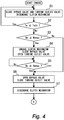
- Fig. 4 and Fig. 5 are flowcharts for explaining control that is executed by the ECU 70 in embodiment 2, Fig. 4 illustrates a first half part, and Fig. 5 illustrates a latter half part. Note that the flowchart organizes and expresses, in a single flowchart, a series of processing of the ECU 70 controlling the turbine outlet valve 22, the clutch mechanism 40 and the bypass valve 60 when the engine 10 is started, and does not express a control routine itself that is executed in the ECU 70.
- step S1 through step S7 in the flow chart illustrated in Fig. 4 Similar processing to step S1 through step S7 in the flowchart illustrated in Fig. 2 is executed. Thereby, when the engine speed Ne reaches the practical upper limit engine speed Nemax or more, closure of the turbine outlet valve 22, opening of the bypass valve 60, and disengagement of the clutch mechanism 40 are performed.
- Fig. 6 is a P-V diagram illustrating an output characteristic of the turbine. Note that Pti shown in Fig. 6 represents a pressure (hereunder, referred to as an "inlet pressure") of steam at an inlet side of the turbine nozzle 201.
- the inlet pressure Pti can be estimated from the water temperature Te of the engine cooling water that is in a proportional relation with the inlet pressure Pti.
- the ECU 70 has a function as an inlet pressure acquiring device that acquires the inlet pressure Pti by using a detection signal of the water temperature sensor 121.
- Pt0 shown in Fig. 6 represents a pressure (hereunder, referred to as an "outlet pressure") of steam at an outlet side of the turbine nozzle 201, and can be detected by the outlet pressure sensor 76.
- the ECU 70 has a function as an outlet pressure acquiring device that acquires the outlet pressure Pt0 by using a detection signal of the outlet pressure sensor 76.
- the output Ht of the turbine 20 is determined by steam pressures before and after the turbine nozzle 201, as illustrated in Fig. 6 .
- the inlet pressure Pti and the outlet pressure Pt0 are estimated or detected, and the net output Ht of the turbine 20 is calculated based on the output characteristic illustrated in Fig. 6 .
- a fluid friction resistance Lf to the turbine blades 202 is calculated (step S22).
- a draft loss, a rotor friction loss and the like are cited.
- the draft loss and the rotor friction loss can be respectively expressed by relational expressions as follows by using a diameter Dt of the turbine 20, the turbine rotation speed Nt, a height Yt of the turbine blade 202 and a steam density ⁇ . Draft loss ⁇ Dt 4 * Nt 3 * Yt 1.5 * ⁇ Rotor friction loss ⁇ Dt 5 * Nt 3 * ⁇
- the diameter Dt of the turbine 20 and the height Yt of the turbine blade 202 are characteristic values of the turbine 20, and the proportionality constants A and B can be determined by an actual machine test or the like. Further, as for the turbine rotation speed Nt, for example, the practical upper limit turbine rotation speed Ntmax is used as the turbine rotation speed which is set as a target when the clutch mechanism 40 is disengaged. Further, the steam density ⁇ is calculated by using the outlet pressure Pt0 of the turbine nozzle 201.
- the target ratio is set at 1.02 that is slightly larger than 1.
- step S23 When establishment of the fluid friction resistance Lf/the net output Ht > 1.02 is recognized as a result of the determination in the present step S23, it is determined that the turbine rotation speed becomes lower than the actual upper limit turbine rotation speed Ntmax, the flow shifts to a next step, and the opening degree of the turbine outlet valve 22 is opened by one step (step S24).
- step S23 When establishment of the fluid friction resistance Lf/the net output Ht > 1.02 is not recognized as a result of the determination in step S23 described above, it is determined that there is a possibility of the turbine rotation speed exceeding the practical upper limit turbine rotation speed Ntmax, the flow shifts to a next step, and the opening degree of the turbine outlet valve 22 is closed by one step (step S25).
- step S26 it is determined whether or not the engine speed Ne is the predetermined practical upper limit engine speed Nemax or more again, next (step S26).
- Ne ⁇ Nemax is recognized as a result, it is determined that if the clutch mechanism 40 is engaged again, there is a fear that the turbine 20 overspeeds, and disengagement of the clutch mechanism 40 is continued by returning to the processing in step S23 described above.
- step S26 it is determined that there is no fear that the turbine 20 overspeeds even if the clutch mechanism 40 is engaged again, so that the flow shifts to step S4, and the clutch mechanism 40 is engaged again.
- the turbine rotation speed can be brought close to the rotation speed set as the target, and therefore reengagement of the clutch mechanism 40 can be smoothly performed.
- the inlet pressure Pti is estimated from the water temperature Te of the engine cooling water, but the inlet pressure Pti may be directly detected by providing a pressure sensor at the inlet side of the turbine nozzle 201.
- the target ratio of the fluid friction resistance Lf/the net output Ht is set as 1.02
- the value of the target ratio is not limited to this. That is, another target ratio value may be used if only the turbine rotation speed can be brought close to the practical upper limit turbine rotation speed Ntmax while overspeed of the turbine rotation speed is prevented.
Landscapes
- Engineering & Computer Science (AREA)
- Chemical & Material Sciences (AREA)
- Combustion & Propulsion (AREA)
- Mechanical Engineering (AREA)
- General Engineering & Computer Science (AREA)
- Engine Equipment That Uses Special Cycles (AREA)
- Control Of Turbines (AREA)
Abstract
Description
- The present invention relates to a Rankine cycle system, and particularly relates to a Rankine cycle system that uses waste heat of an internal combustion engine. Background
- Conventionally, for example,
JP 2010-242518 A -
- [PTL 1]
JP 2010-242518 A - [PTL 2]
JP 2013-234662 A - In the aforementioned prior art, in the case where it is determined that the turbine rotation speed is not in a region where the Rankine cycle system can be operated safely, the clutch that is provided at the transmission is disengaged and disconnection of the crankshaft and the rotating shaft is performed. However, the turbine rotates by inertia even after the clutch is disengaged. Consequently, when the clutch is disengaged in the process of the turbine rotation speed increasing, there arises a fear that the turbine rotation speed increases by inertia, even after the clutch is disengaged, to overspeed.
- The present invention is made in the light of the problem as described above, and an object of the present invention is to provide a Rankine cycle system that can restrain overspeed of a turbine in the Rankine cycle system that transmits rotation of the turbine to an output shaft of an internal combustion engine.
- In order to attain the above described object, a first invention is a Rankine cycle system, including
a boiler that boils a liquid-phase heat medium by waste heat of an internal combustion engine to change the liquid-phase heat medium into a gas-phase heat medium,
a superheater that superheats a gas-phase heat medium discharged from the boiler by heat exchange with exhaust gas of the internal combustion engine,
a turbine that rotates by receiving supply of a gas-phase heat medium passing through the superheater,
a condenser that condenses a gas-phase heat medium passing through the turbine and returns the gas-phase heat medium to a liquid-phase heat medium,
a control valve that is provided between the turbine and the condenser,
a power transmission path that transmits rotation of the turbine to an output shaft of the internal combustion engine,
a clutch mechanism that connects or disconnects the power transmission pathway, and
a controller that is configured to operate the control valve in a closing direction, when the power transmission pathway is disconnected by an action of the clutch mechanism. - A second invention is such that, in the first invention,
the clutch mechanism is configured so that the power transmission pathway is disconnected when an engine speed of the internal combustion engine exceeds an engine speed threshold value. - A third invention is such that, in the first or the second invention, the Rankine cycle system further includes
a bypass path that branches from between the boiler and the superheater to join into between the control valve and the condenser, and
a bypass valve that is provided in the bypass path,
wherein the controller is configured to open the bypass valve when the controller operates the control valve in the closing direction. - A fourth invention is such that, in any one of the first to the third inventions, the Rankine cycle system further includes
a turbine rotation speed acquiring device that acquires a rotation speed of the turbine,
wherein the controller is configured to adjust an opening degree of the control valve so that the rotation speed of the turbine comes close to a turbine rotation speed threshold value, when the power transmission pathway is disconnected by the action of the clutch mechanism. - A fifth invention is such that, in any one of the first to the third inventions, the Rankine cycle system further includes
an inlet pressure acquiring device that acquires an inlet pressure that is a steam pressure of a gas-phase heat medium at an inlet side of the turbine, and
an outlet pressure acquiring device that acquires an outlet pressure that is a steam pressure of a gas-phase heat medium at an outlet side of the turbine,
wherein the controller is configured to calculate an output of the turbine from the inlet pressure and the outlet pressure, calculate a fluid friction resistance by blades of the turbine from the outlet pressure, and operate the control valve so that a ratio of the fluid friction resistance to the output of the turbine comes close to a predetermined target ratio when the power transmission pathway is disconnected by the action of the clutch mechanism. - According to the first invention, the control valve is provided between the turbine and the condenser of the Rankine cycle system. The control valve is operated in the closing direction in the case of the power transmission circuit being disconnected by the action of the clutch mechanism. When the control valve is operated in the closing direction, a steam density in the turbine becomes high, and thereby the rotation resistance of the turbine increases. Consequently, according to the present invention, it becomes possible to restrain overspeed of the turbine effectively when the power transmission circuit is disconnected by the action of the clutch mechanism.
- According to the second invention, the clutch mechanism is configured so that the power transmission pathway is disconnected when the engine speed of the internal combustion engine exceeds the engine speed threshold value. Consequently, according to the present invention, the turbine rotation speed can be prevented from being higher than the turbine rotation speed that corresponds to the engine speed threshold value.
- According to the third invention, the bypass valve controller is configured so that the bypass valve opens when the control valve is operated in the closing direction. Consequently, according to the present invention, steam that is introduced into the turbine can be caused to escape through the bypass valve, and therefore, it becomes possible to restrain excessive increase in the steam pressure at the turbine inlet side effectively.
- According to the fourth invention, the opening degree of the control valve is adjusted so that the rotation speed of the turbine comes close to the turbine rotation speed threshold value when the power transmission circuit is disconnected. Consequently, according to the present invention, it becomes possible to restrain overspeed of the turbine, and enhance the turbine rotation speed in preparation for the case of connecting the power transmission pathway.
- According to the fifth invention, the inlet side steam pressure that is the steam pressure of the gas-phase heat medium at the turbine inlet side, and the outlet side steam pressure that is the steam pressure of the gas-phase heat medium at the turbine outlet side are acquired. The turbine output is calculated based on the inlet side stream pressure and the outlet side stream pressure which are acquired, and the fluid friction resistance by the blades of the turbine is calculated based on the outlet side steam pressure. Subsequently, the opening degree of the control valve is controlled so that the ratio of the fluid friction resistance to the turbine output which is calculated comes close to the predetermined target ratio. In a state in which the turbine output and the fluid friction resistance are balanced with each other, the turbine rotation speed is kept constant. Consequently, according to the present invention, it becomes possible to restrain overspeed of the turbine, and enhance the turbine rotation speed in preparation for smooth reconnection of the power transmission pathway.
-
-
Fig. 1 is a diagram schematically illustrating an internal combustion engine in which a Rankine cycle system ofembodiment 1 of the present invention is incorporated. -
Fig. 2 is a flowchart illustrating control that is executed inembodiment 1 of the present invention. -
Fig. 3 is a diagram schematically illustrating an internal combustion engine in which a Rankine cycle system ofembodiment 2 of the present invention is incorporated. -
Fig. 4 is a flowchart illustrating a first half part of control that is executed inembodiment 2 of the present invention. -
Fig. 5 is a flowchart illustrating a latter half part of the control that is executed inembodiment 2 of the present invention. -
Fig. 6 is a P-V diagram illustrating an output characteristic of a turbine. -
Embodiment 1 of the present invention will be described with reference to the drawings. Note that common elements in the respective drawings will be assigned with the same reference signs and redundant explanation will be omitted. Further, the present invention is not limited by embodiments as follows. -
Fig. 1 is a diagram schematically illustrating an internal combustion engine in which a Rankine cycle system ofembodiment 1 of the present invention is incorporated. ARankine cycle system 100 is equipped with aheat medium passage 12 that is formed inside an internal combustion engine (hereunder, also referred to as an "engine") 10. Theheat medium passage 12 includes a water jacket that is formed in a cylinder block and a cylinder head of theengine 10. Awater temperature sensor 121 is attached to theheat medium passage 12. Theengine 10 is cooled by boiling a heat medium that flows through an inside of theheat medium passage 12 by heat of theengine 10 and evaporating a part of the heat medium. That is, theheat medium passage 12 functions as a boiler that boils the heat medium by waste heat of theengine 10 and changes a liquid-phase heat medium to a gas-phase heat medium. A configuration of theheat medium passage 12 is not specially limited as long as theheat medium passage 12 is a passage that can pass through an inside of theengine 10. Further, a kind of the heat medium that is caused to flow through theheat medium passage 12 is not specially limited as long as the heat medium boils by heat reception from theengine 10. - A first gas-phase
heat medium path 14 is connected to theheat medium passage 12. The first gas-phaseheat medium path 14 is a path for leading out the heat medium that receives waste heat of theengine 10 in theheat medium passage 12 to an outside of theengine 10, and is configured by a tube or a hose that can resist a high temperature and a high pressure. In the first gas-phaseheat medium path 14, a gas-liquid separator 16, asuperheater 18, aturbine 20 and aturbine outlet valve 22 are disposed in sequence from a side near to theengine 10. Acondenser 24 is connected to an end portion of the first gas-phaseheat medium path 14. - The gas-
liquid separator 16 is for separating the heat medium that is led out from theheat medium passage 12 in theengine 10 into a gas-phase heat medium and a liquid-phase heat medium. The gas-phase heat medium that is separated in the gas-liquid separator 16 is fed to thesuperheater 18 that is provided at a further downstream side in the first gas-phaseheat medium path 14. The liquid-phase heat medium that is separated in the gas-liquid separator 16 is stored in the gas-liquid separator 16. A first liquid-phaseheat medium path 26 is connected to a lower end of the gas-liquid separator 16. The first liquid-phaseheat medium path 26 is connected to theheat medium passage 12 inside theengine 10. The first liquid-phaseheat medium path 26 is provided with afirst water pump 28. Thefirst water pump 28 is configured as a mechanical pump with a crankshaft included by theengine 10 as a drive source. Note that as for thefirst water pump 28, an electrically-driven centrifugal pump can be also adopted. When thefirst water pump 28 is operated, a part of the liquid-phase heat medium that is stored in the gas-liquid separator 16 is fed to theheat medium passage 12 via the first liquid-phaseheat medium path 26. The gas-liquid separator 16 is provided with aliquid level sensor 161. Theliquid level sensor 161 is for monitoring excess and deficiency of the liquid-phase heat medium that is stored in the gas-liquid separator 16. - Further, the
Rankine cycle system 100 is equipped with an exhaustheat steam generator 30. The exhaustheat steam generator 30 is disposed midway in anexhaust path 8 of theengine 10. The liquid-phase heat medium is introduced into the exhaustheat steam generator 30 via a second liquid-phaseheat medium path 32 that is connected to a lower end of the gas-liquid separator 16. The introduced liquid-phase heat medium is superheated and boils by heat exchange with exhaust gas in theexhaust path 8, and a part of the heat medium becomes steam. That is, the exhaustheat steam generator 30 functions as a boiler that boils the heat medium by waste heat of theengine 10 and changes the heat medium to the gas-phase heat medium from the liquid-phase heat medium. The gas-phase heat medium that becomes steam is led out via a second gas-phaseheat medium path 34 and is returned to the gas-liquid separator 16 again. - The
superheater 18 is disposed in the exhaust path 8 (a site of (a) inFig. 1 ) at an upstream side of the exhaustheat steam generator 30. The gas-phase heat medium that is introduced into thesuperheater 18 from the first gas-phaseheat medium path 14 is further superheated by heat exchange with the exhaust gas in theexhaust path 8 to be superheated steam. The superheated steam is introduced into theturbine 20 which is further downstream in the first gas-phaseheat medium path 14. Theturbine 20 is configured by including aturbine nozzle 201 that decompresses the superheated steam that is introduced from the first gas-phaseheat medium path 14, and aturbine rotary shaft 203 to which a plurality ofturbine blades 202 are fixed. The superheated steam that is introduced into theturbine 20 is decompressed in theturbine nozzle 201 and is blown to theturbine blades 202. The superheated stream is blown to theturbine blades 202, whereby theturbine rotary shaft 203 rotates. - The
turbine rotary shaft 203 of theturbine 20 is connected to acrankshaft 38 as the output shaft of theengine 10 via apower transmission pathway 36 such as a speed reducer. Aclutch mechanism 40 for connecting or disconnecting thepower transmission pathway 36 is provided halfway in thepower transmission pathway 36. Theclutch mechanism 40 is configured as an electromagnetic clutch capable of connecting or disconnecting thepower transmission pathway 36 by an electrical signal. Further, the Rankine cycle system is provided with aturbine rotation sensor 72 for detecting a rotation speed Nt of theturbine rotary shaft 203, and acrank angle sensor 74 for detecting a rotation speed Ne of thecrankshaft 38. - The
turbine outlet valve 22 functions as a control valve that adjusts an opening degree of the first gas-phaseheat medium path 14 between theturbine 20 and thecondenser 24. When theturbine outlet valve 22 is controlled to a closing side, a steam density in theturbine 20 can be increased with this. - The
condenser 24 functions as a condenser that condenses the gas-phase heat medium passing through theturbine 20 to return the gas-phase heat medium to a liquid-phase heat medium. One end of a third liquid-phaseheat medium path 42 is connected to a lower end of thecondenser 24. In the third liquid-phaseheat medium path 42, acatch tank 44, asecond water pump 46 and a first on-offvalve 48 are disposed in sequence from a side near to thecondenser 24. An end portion of the third liquid-phaseheat medium path 42 is connected to a lower end of the gas-liquid separator 16. - The gas-phase heat medium that is introduced into the
condenser 24 from theturbine 20 via the first gas-phaseheat medium path 14 is condensed in thecondenser 24 to return to the liquid-phase heat medium, and is temporarily stored in thecatch tank 44. Thesecond water pump 46 is an electrically-driven pump for feeding the liquid-phase heat medium stored in thecatch tank 44 to the gas-liquid separator 16 via the third liquid-phaseheat medium path 42. Drive of thesecond water pump 46 is controlled based on an output signal of theliquid level sensor 161 so that no excess or deficiency occurs to the liquid-phase heat medium that is stored in the gas-liquid separator 16. Further, the first on-offvalve 48 is a valve that is opened and closed in response to start and stop of drive of thesecond water pump 46. The first on-offvalve 48 is closed in a period in which thesecond water pump 46 stops, whereby a backflow of the liquid-phase heat medium to a side of thecatch tank 44 is prevented. - A lower end of the
catch tank 44 is connected to a lower end of areserve tank 52 via a fourth liquid-phaseheat medium path 50. A second on-offvalve 54 is provided halfway in the fourth liquid-phaseheat medium path 50. Anupper pipe 56 having an end portion opened to the atmosphere is connected to an upper end of thereserve tank 52. - Further, the
Rankine cycle system 100 is equipped with abypass path 58 that connects an upper end of the gas-liquid separator 16 and a spot between theturbine outlet valve 22 and thecondenser 24 in the first gas-phaseheat medium path 14. Thebypass path 58 is provided with abypass valve 60 and abypass nozzle 62 in sequence from a side near to the gas-liquid separator 16. When thebypass valve 60 is opened, the gas-phase heat medium in the gas-liquid separator 16 is introduced into thebypass nozzle 62. The introduced gas-phase heat medium is introduced into thecondenser 24 after being decompressed at the time of passing through thebypass nozzle 62. Thereby, a steam pressure at an inlet side of theturbine 20 in the first gas-phaseheat medium path 14 is decompressed. Thebypass path 58 can be a path that bypasses thesuperheater 18, theturbine 20 and theturbine outlet valve 22 from the first gas-phaseheat medium path 14, and does not necessarily have to be connected to the upper end of the gas-liquid separator 16. That is, thebypass path 58 can be configured as a path that branches from a spot between theheat medium passage 12 and thesuperheater 18 in the first gas-phaseheat medium path 14 and joins the spot between theturbine outlet valve 22 and thecondenser 24. - Further, the
Rankine cycle system 100 is equipped with an ECU (Electronic Control Unit) 70 as a controller. TheECU 70 is equipped with at least an input-output interface, a memory and a central processing unit (CPU). The input-output interface is provided to take in sensor signals from various sensors that are attached to theRankine cycle system 100 or theengine 10 on which theRankine cycle system 100 is mounted, and output operation signals to various actuators included by theRankine cycle system 100. The sensors from which theECU 70 takes in the signals include various sensors for acquiring an engine operation state such as thecrank angle sensor 74, in addition to theturbine rotation sensor 72, thewater temperature sensor 121 and theliquid level sensor 161 described above. The actuators to which theECU 70 issues the operation signals include various actuators for controlling an operation of theengine 10, in addition to theturbine outlet valve 22, thebypass valve 60, the first on-offvalve 48, the second on-offvalve 54, theclutch mechanism 40, thefirst water pump 28 and thesecond water pump 46 described above. In the memory, various control programs, maps and the like are stored. The CPU reads and executes the control program or the like from the memory, and generates the operation signals of various actuators based on the sensor signals that are taken in. - Next, a basic operation of the
engine 10 equipped with theRankine cycle system 100 ofembodiment 1 will be described. Note that inFig. 1 , flows of the liquid-phase heat medium are expressed by thick solid lines, and flows of the gas-phase heat medium (steam) is expressed by thick broken lines. - The
Rankine cycle system 100 ofembodiment 1 recovers energy by the waste heat of theengine 10 as rotational energy of theturbine 20, and assists in rotation of the output shaft of theengine 10. First, the Rankine cycle that is realized in theRankine cycle system 100 will be described. Theheat medium passage 12 and the exhaustheat steam generator 30 function as a boiler that receives the waste heat of theengine 10 and boils the liquid-phase heat medium. When the liquid-phase heat medium boils, a part of the liquid-phase heat medium changes into the gas-phase heat medium (steam). The gas-phase heat medium that is generated in theheat medium passage 12 is introduced into the gas-liquid separator 16 via the first gas-phaseheat medium path 14. Further, the gas-phase heat medium generated in the exhaustheat steam generator 30 is introduced into the gas-liquid separator 16 via the second gas-phaseheat medium path 34. The gas-phase heat medium in the gas-liquid separator 16 is introduced into thesuperheater 18 via the first gas-phaseheat medium path 14. The gas-phase heat medium further receives the exhaust heat of theengine 10 in a process of passing through thesuperheater 18, and thereby changes to superheated steam with a higher temperature and higher pressure. The superheated steam passing through thesuperheater 18 is introduced into theturbine 20 via the first gas-phaseheat medium path 14. - In the
turbine 20, the introduced superheated steam is decompressed and expanded by theturbine nozzle 201, and thereafter is blown to theturbine blades 202. Thereby, heat energy of the superheated steam is taken out as a rotational motion of theturbine 20. The low-pressure gas-phase heat medium that passes through theturbine 20 is introduced into thecondenser 24 via the first gas-phaseheat medium path 14. The introduced gas-phase heat medium is cooled in thecondenser 24 to change to a liquid-phase heat medium, and is primarily stored in thecatch tank 44 via the third liquid-phaseheat medium path 42. When deficiency of the liquid-phase heat medium in the gas-liquid separator 16 is detected by theliquid level sensor 161, thesecond water pump 46 is driven, and the liquid-phase heat medium in thecatch tank 44 is introduced into the gas-liquid separator 16 via the third liquid-phaseheat medium path 42. - When the Rankine cycle is realized by the
Rankine cycle system 100 in this way, the waste heat of theengine 10 is converted into the rotational energy of theturbine 20. Theturbine rotary shaft 203 is connected to thecrankshaft 38 via thepower transmission pathway 36 and theclutch mechanism 40. Consequently, the rotational energy of theturbine 20 is directly used in rotation of thecrankshaft 38 by engaging theclutch mechanism 40. Thereby, energy efficiency of the entire system can be enhanced, and therefore enhancement in fuel efficiency can be expected. - Next, a characteristic operation of the
Rankine cycle system 100 ofembodiment 1 will be described. The turbine rotation speed with high turbine efficiency is several ten thousands rpm/min., and therefore a reduction ratio R of the speed reducer included by thepower transmission pathway 36 is set so that efficiency of theturbine 20 becomes high in a practical region of an engine speed. Consequently, when the engine speed of theengine 10 reaches a speed in a high rotation region that is rarely used practically, the rotation speed of theturbine 20 becomes excessively high, and durability, noise, vibration and the like of the turbine become problems. Thus, in theRankine cycle system 100 ofembodiment 1, in a case where the engine speed Ne of theengine 10 becomes higher than a practical upper limit engine speed Nemax, theclutch mechanism 40 is disengaged to disconnect thepower transmission pathway 36. - However, even when the
power transmission pathway 36 is disconnected by an operation of disengaging theclutch mechanism 40, the overspeed of theturbine 20 is not always prevented reliably. That is, in a case where the engine speed Ne abruptly increases, and reaches the practical upper limit engine speed Nemax, the turbine rotation speed may increase by rotation acceleration of theturbine 20 even after thepower transmission pathway 36 is disconnected. In the case like this, there arises a fear that theturbine 20 overspeeds. - Thus, in the
Rankine cycle system 100 inembodiment 1, theturbine outlet valve 22 is disposed at an outlet side of theturbine 20, and theturbine outlet valve 22 is closed when theclutch mechanism 40 is disengaged and thepower transmission pathway 36 is disconnected. When theturbine outlet valve 22 is closed, a steam density in theturbine 20 increases, and therefore, resistance of fluid friction to theturbine blades 202 abruptly increases. Consequently, if theturbine outlet valve 22 is closed with disengagement of theclutch mechanism 40, the turbine rotation speed is reliably reduced, and overspeed can be restrained. - When the superheated steam continues to be supplied from the
superheater 18 while theclutch mechanism 40 is disengaged and theturbine outlet valve 22 is closed, the steam pressure at the inlet side of theturbine 20 increases. Thus, in theRankine cycle system 100 ofembodiment 1, in a case where theclutch mechanism 40 is disengaged, theturbine outlet valve 22 is closed and thebypass valve 60 is opened. When thebypass valve 60 is opened, the gas-phase heat medium in the gas-liquid separator 16 passes through thebypass path 58 and is introduced into thebypass nozzle 62. The gas-phase heat medium is decompressed at a time of passing through thebypass nozzle 62, and is introduced into the first gas-phaseheat medium path 14 between theturbine outlet valve 22 and thecondenser 24. That is, when thebypass valve 60 is opened, the gas-phase heat medium in the gas-liquid separator 16 is introduced into thecondenser 24 by bypassing thesuperheater 18, theturbine 20 and theturbine outlet valve 22. Thereby, steam pressure at the inlet side of theturbine 20 can be effectively released. - Further, as described above, in the
Rankine cycle system 100 inembodiment 1, in the case where the engine speed Ne exceeds the practical upper limit engine speed Nemax, theclutch mechanism 40 is disengaged and theturbine outlet valve 22 is closed. In a period in which theturbine outlet valve 22 is closed, the steam density inside theturbine 20 increases, and with this, the turbine rotation speed Nt reduces. When the turbine rotation speed Nt is reduced to an extremely low speed, theclutch mechanism 40 cannot be smoothly engaged thereafter, when the engine speed Ne reduces to the practical upper limit engine speed Nemax and theclutch mechanism 40 is engaged again, and theturbine 20 is unlikely to assist in engine rotation effectively. - Thus, in the
Rankine cycle system 100 inembodiment 1, in the case where theclutch mechanism 40 is disengaged, the turbine rotation speed Nt is controlled based on the opening degree of theturbine outlet valve 22. In more detail, when theclutch mechanism 40 is disengaged, overspeed of theturbine 20 needs to be restrained, and therefore, theturbine outlet valve 22 is fully closed temporarily. Thereafter, the turbine rotation speed Nt is detected from the signal of theturbine rotation sensor 72, and the opening degree of theturbine outlet valve 22 is feedback-controlled so that the detected turbine rotation speed Nt comes close to a predetermined practical upper limit turbine rotation speed Ntmax. The practical upper limit turbine rotation speed Ntmax is a turbine rotation speed in a case where theclutch mechanism 40 is engaged in a state in which the engine speed Ne is the practical upper limit engine speed Nemax. According to the control like this, the turbine rotation speed Nt in the period in which theclutch mechanism 40 is disengaged is controlled to the practical upper limit turbine rotation speed Ntmax, and therefore it becomes possible to engage theclutch mechanism 40 smoothly when the engine speed Ne is reduced to the practical upper limit engine speed Nemax. - The respective functions of the
ECU 70 in theRankine cycle system 100 are realized by a processing circuit. That is, theECU 70 includes a processing circuit that is configured to operate theturbine outlet valve 22 which is the control valve in a closing direction, open the bypass valve, and adjust the opening degree of the control valve so that the rotation speed of the turbine comes close to a turbine rotation speed threshold value, when the power transmission pathway is disconnected by an action of theclutch mechanism 40. The processing circuit may be exclusive hardware, a CPU (also referred to as a Central Processing Unit, a central processing device, a processing unit, an arithmetic unit, a microprocessor, a microcomputer, a processor, and a DSP) that executes a program stored in the memory. - When the processing circuit is exclusive hardware, the processing circuit corresponds to a single circuit, a composite circuit, a programmed processor, a parallel-programmed processor, ASIC, FPGA or a combination of them. Further, when the processing circuit is the CPU, the respective functions of the
ECU 70 is realized by software, firmware, or a combination of software and firmware. The software and the firmware are described as programs, and are stored in the memory. The processing circuit realizes the respective functions by reading and executing the programs stored in the memory. That is, theECU 70 includes the memory for storing the program by which steps of operating theturbine outlet valve 22 in the closing direction when the power transmission pathway is disconnected by the action of theclutch mechanism 40, opening the bypass valve, and adjusting the opening degree of the control valve so that the rotation speed of the turbine comes close to the turbine rotation speed threshold value are resultantly executed, when the program is executed by the processing circuit. Further, it can be said that these programs cause the computer to execute a procedure and a method of processing that is executed by theECU 70. Here, nonvolatile or volatile semiconductor memories such as a RAM, a ROM, a flash memory, an EPROM, and an EPPROM correspond to the memory. In this way, the processing circuit can realize the aforementioned respective functions by hardware, software, firmware or a combination of the hardware, software and firmware. - Next, specific processing of control that is executed in the Rankine cycle system of
embodiment 1 will be described.Fig. 2 is a flowchart for explaining control that is executed by theECU 70 inembodiment 1. Note that the flowchart organizes and expresses, in a single flowchart, a series of processing of theECU 70 controlling theturbine outlet valve 22, theclutch mechanism 40 and thebypass valve 60 when theengine 10 is started, and does not express a control routine itself that is executed in theECU 70. - In the flowchart illustrated in
Fig. 2 , thebypass valve 60 and theturbine outlet valve 22 are closed, and theclutch mechanism 40 is disengaged, when theengine 10 is started first (step S1). Next, it is determined whether or not the water temperature Te of engine cooling water (heat medium) detected by thewater temperature sensor 121 is a predetermined warming-up temperature Teth or less (step S2). As for the warming-up temperature Teth, a value that is set in advance as an engine water temperature at which warming-up of theengine 10 is completed is read. When establishment of Te≥Teth is not recognized as a result, it is determined that engine warming-up is not completed yet, and the flow goes to step S1. - When establishment of Te≥Teth is recognized in step S2 described above, it is determined that the
heat medium passage 12 functions as the boiler because engine warming-up is completed, the flow goes to a next step, and it is determined whether or not the engine speed Ne which is detected by thecrank angle sensor 74 is the predetermined practical upper limit engine speed Nemax or less (step S3). As for the practical upper limit engine speed Nemax, a value that is set in advance is read, as an engine speed at which the turbine rotation speed reaches an upper limit in a state where theclutch mechanism 40 is engaged. When establishment of Ne≤Nemax is recognized as a result, it is determined that there is no fear that theturbine 20 overspeeds even if theclutch mechanism 40 is engaged, the flow goes to a next step, and engagement of theclutch mechanism 40, opening of theturbine outlet valve 22 and closure of thebypass valve 60 are performed (step S4) - Next, it is determined whether or not the engine speed Ne is the predetermined practical upper limit engine speed Nemax or more (step S5). When establishment of Ne≥Nemax is not recognized as a result, it is determined that there is no fear that the
turbine 20 overspeeds yet, and processing in the present step S5 is executed again after engagement of theclutch mechanism 40 is continued. When establishment of Ne≥Nemax is recognized in thepresent step 5, or establishment of Ne≤Nemax is not recognized in step S3 described above, it is determined that there is a fear that theturbine 20 overspeeds in the state in which theclutch mechanism 40 is disengaged, the flow goes to a next step, theturbine outlet valve 22 is closed and thebypass valve 60 is opened (step S6). Next, theclutch mechanism 40 is disengaged (step S7). - Next, it is determined whether or not the turbine rotation speed Nt of the
turbine 20 is lower than the practical upper limit turbine rotation speed Ntmax (step S8). The practical upper limit turbine rotation speed Ntmax is the turbine rotation speed corresponding to the practical upper limit engine speed Nemax, and is the rotation speed that satisfies Ntmax=NemaxxR when the speed reduction ratio of thepower transmission pathway 36 is set as R. When establishment of Nt<Ntmax is recognized as a result, theturbine outlet valve 22 is controlled to open by one step so that the turbine rotation speed Nt comes close to the practical upper limit turbine rotation speed Ntmax (step S9). When establishment of Nt<Ntmax is not recognized in step S8 described above, theturbine outlet valve 22 is controlled to close by one step so that the turbine rotation speed Nt comes close to the practical upper limit turbine rotation speed Ntmax (step S10). - When the processing in step S9 or step S10 described above is performed, it is determined again whether or not the engine speed Ne is the predetermined practical upper limit engine speed Nemax or more (step S11). When establishment of Ne≥Nemax is recognized as a result, it is determined that there is a fear that the
turbine 20 overspeeds when theclutch mechanism 40 is engaged again, and disengagement of theclutch mechanism 40 is continued by returning to the processing in step S8 described above. When establishment of Ne≥Nemax is not recognized in the present step S11, it is determined that there is no fear that theturbine 20 overspeeds even when theclutch mechanism 40 is engaged again, the flow goes to step S4 described above, and theclutch mechanism 40 is engaged again. - As described above, according to the
Rankine cycle system 100 inembodiment 1, theturbine outlet valve 22 is closed when theclutch mechanism 40 is disconnected, and therefore, it becomes possible to restrain overspeed of the turbine effectively. - Incidentally, in the system of
embodiment 1 described above, the electromagnetic clutch capable of connecting or disconnecting thepower transmission pathway 36 by an electrical signal is used as theclutch mechanism 40. Theclutch mechanism 40 may be configured as a one-way clutch that transmits a rotational force in only one direction, or another known clutch. This is also applied to a system inembodiment 2 that will be described later. - When a one-way clutch is adopted as the
clutch mechanism 40, theclutch mechanism 40 is automatically engaged when the engine speed Ne ≤ the turbine rotation speed Nt/the speed reduction ratio R is established, and is automatically disengaged when the engine speed Ne < the turbine rotation speed Nt/the speed reduction ratio R is established. Consequently, processing of disengaging theclutch mechanism 40 in step S7 described above is automatically performed by theturbine outlet valve 22 being closed to reduce the turbine rotation speed in step S6. - Further, in the system of
embodiment 1 described above, theRankine cycle system 100 having the heat medium that recovers the waste heat of theengine 10 as the working fluid is described, but theRankine cycle system 100 does not necessarily have to have the heat medium flowing in theheat medium passage 12 of theengine 10 as the working fluid. That is, a configuration may be adopted, in which the heat medium of theRankine cycle system 100 is made a different system from the heat medium of theengine 10, and heat exchange is performed with the heat medium of theengine 10 by a heat exchanger. This is also applied to the system inembodiment 2 that will be described later. - Further, although in the system of
embodiment 1 described above, disengagement and engagement of theclutch mechanism 40 are performed based on whether or not the engine speed Ne exceeds the practical upper limit engine speed Nemax, disengagement and engagement of theclutch mechanism 40 may be performed based on whether or not the turbine rotation speed Nt which is detected by theturbine rotation sensor 72 exceeds the practical upper limit turbine rotation speed. - Further, although in the system in
embodiment 1 described above, both theheat medium passage 12 and the exhaustheat steam generator 30 are used as the boiler of theRankine cycle system 100, either one of theheat medium passage 12 or the exhaustheat steam generator 30 may be used. Further, as for the boiler, another known configuration such as a heat exchanger may be used as long as it boils the heat medium of the Rankine cycle by using the waste heat of theengine 10. This is also applied to the system ofembodiment 2 that will be described later. - Further, in the system of
embodiment 1 described above, theturbine outlet valve 22 is fully closed when theclutch mechanism 40 is disengaged. However, the opening degree of theturbine outlet valve 22 does not have to be full closure, because if theturbine outlet valve 22 is controlled to at least a closing side, the turbine rotation speed can be reduced. This is also applied to the system ofembodiment 2 that will be described later. - Note that in the system of
embodiment 1 described above, the practical upper limit engine speed Nemax corresponds to an "engine speed threshold value" in a second invention. The practical upper limit turbine rotation speed Ntmax corresponds to a "turbine rotation speed threshold value" in a fourth invention. Theturbine rotation sensor 72 corresponds to a "turbine rotation speed acquiring device" in the fourth invention. - Next,
embodiment 2 of the present invention will be described with reference to the drawings. -
Fig. 3 is a diagram schematically illustrating an internal combustion engine in which a Rankine cycle system ofembodiment 2 of the present invention is incorporated. ARankine cycle system 200 illustrated inFig. 3 has a similar configuration to the configuration of theRankine cycle system 100 illustrated inFig. 1 described above, except for a point that anoutlet pressure sensor 76 is provided in a position between theturbine 20 and theturbine outlet valve 22 in the first gas-phaseheat medium path 14, and a point that theRankine cycle system 200 is not equipped with theturbine rotation sensor 72. - In the
Rankine cycle system 100 ofembodiment 1 described above, the opening degree of theturbine outlet valve 22 is controlled so that the turbine rotation speed Nt that is detected by theturbine rotation sensor 72 gets close to the practical upper limit turbine rotation speed Ntmax, after theturbine outlet valve 22 is closed and theclutch mechanism 40 is disengaged. In contrast with this, theRankine cycle system 200 of thepresent embodiment 2 has a feature in a point that the opening degree of theturbine outlet valve 22 after theclutch mechanism 40 being disengaged is controlled without using the rotation speed information that is obtained by theturbine rotation sensor 72. Hereunder, specific processing of control that is executed in theRankine cycle system 200 ofembodiment 2 will be described in detail in accordance with a flowchart. -
Fig. 4 andFig. 5 are flowcharts for explaining control that is executed by theECU 70 inembodiment 2,Fig. 4 illustrates a first half part, andFig. 5 illustrates a latter half part. Note that the flowchart organizes and expresses, in a single flowchart, a series of processing of theECU 70 controlling theturbine outlet valve 22, theclutch mechanism 40 and thebypass valve 60 when theengine 10 is started, and does not express a control routine itself that is executed in theECU 70. - In processing of step S1 through step S7 in the flow chart illustrated in
Fig. 4 , similar processing to step S1 through step S7 in the flowchart illustrated inFig. 2 is executed. Thereby, when the engine speed Ne reaches the practical upper limit engine speed Nemax or more, closure of theturbine outlet valve 22, opening of thebypass valve 60, and disengagement of theclutch mechanism 40 are performed. - When the processing in step S7 is executed, the flow goes to step S21 in the flowchart illustrated in
Fig. 5 next. In this step, a net output Ht of theturbine 20 is calculated (step S21).Fig. 6 is a P-V diagram illustrating an output characteristic of the turbine. Note that Pti shown inFig. 6 represents a pressure (hereunder, referred to as an "inlet pressure") of steam at an inlet side of theturbine nozzle 201. The inlet pressure Pti can be estimated from the water temperature Te of the engine cooling water that is in a proportional relation with the inlet pressure Pti. That is, theECU 70 has a function as an inlet pressure acquiring device that acquires the inlet pressure Pti by using a detection signal of thewater temperature sensor 121. Further, Pt0 shown inFig. 6 represents a pressure (hereunder, referred to as an "outlet pressure") of steam at an outlet side of theturbine nozzle 201, and can be detected by theoutlet pressure sensor 76. That is, theECU 70 has a function as an outlet pressure acquiring device that acquires the outlet pressure Pt0 by using a detection signal of theoutlet pressure sensor 76. The output Ht of theturbine 20 is determined by steam pressures before and after theturbine nozzle 201, as illustrated inFig. 6 . In the present step, the inlet pressure Pti and the outlet pressure Pt0 are estimated or detected, and the net output Ht of theturbine 20 is calculated based on the output characteristic illustrated inFig. 6 . - Next, a fluid friction resistance Lf to the
turbine blades 202 is calculated (step S22). As a typical example of the fluid friction resistance to theturbine blades 202, for example, a draft loss, a rotor friction loss and the like are cited. The draft loss and the rotor friction loss can be respectively expressed by relational expressions as follows by using a diameter Dt of theturbine 20, the turbine rotation speed Nt, a height Yt of theturbine blade 202 and a steam density γ.
- Accordingly, the fluid friction resistance Lf to the
turbine blades 202 can be calculated by a relational expression shown in expression (2) as follows. Note that A and B in the expression are proportionality constants.
- The diameter Dt of the
turbine 20 and the height Yt of theturbine blade 202 are characteristic values of theturbine 20, and the proportionality constants A and B can be determined by an actual machine test or the like. Further, as for the turbine rotation speed Nt, for example, the practical upper limit turbine rotation speed Ntmax is used as the turbine rotation speed which is set as a target when theclutch mechanism 40 is disengaged. Further, the steam density γ is calculated by using the outlet pressure Pt0 of theturbine nozzle 201. - Next, it is determined whether or not the fluid friction resistance Lf/the net output Ht is larger than a predetermined target ratio (step S23). The fluid friction resistance Lf/the net output Ht is the ratio that is used to determine whether it is under a condition in which the turbine rotation speed reduces or a condition in which the turbine rotation speed increases, and when the fluid friction resistance Lf/the net output Ht=1 is established, the turbine rotation speed is kept at the practical upper limit turbine rotation speed Ntmax. However, if the fluid friction resistance Lf/the net output Ht<1 is established, there arises a fear that the turbine rotation speed increases to overspeed, so that in the present step, the target ratio is set at 1.02 that is slightly larger than 1. When the opening degree of the
turbine outlet valve 22 is controlled so that the fluid friction resistance Lf/net output Ht = 1.02 is established in this way, the turbine rotation speed is kept at the rotation speed which is slightly lower than the actual upper limit turbine rotation speed Ntmax. - When establishment of the fluid friction resistance Lf/the net output Ht > 1.02 is recognized as a result of the determination in the present step S23, it is determined that the turbine rotation speed becomes lower than the actual upper limit turbine rotation speed Ntmax, the flow shifts to a next step, and the opening degree of the
turbine outlet valve 22 is opened by one step (step S24). - When establishment of the fluid friction resistance Lf/the net output Ht > 1.02 is not recognized as a result of the determination in step S23 described above, it is determined that there is a possibility of the turbine rotation speed exceeding the practical upper limit turbine rotation speed Ntmax, the flow shifts to a next step, and the opening degree of the
turbine outlet valve 22 is closed by one step (step S25). - When the processing in step S24 or step S25 described above is performed, it is determined whether or not the engine speed Ne is the predetermined practical upper limit engine speed Nemax or more again, next (step S26). When establishment of Ne≥Nemax is recognized as a result, it is determined that if the
clutch mechanism 40 is engaged again, there is a fear that theturbine 20 overspeeds, and disengagement of theclutch mechanism 40 is continued by returning to the processing in step S23 described above. When establishment of Ne≥Nemax is not recognized in step S26, it is determined that there is no fear that theturbine 20 overspeeds even if theclutch mechanism 40 is engaged again, so that the flow shifts to step S4, and theclutch mechanism 40 is engaged again. - As described above, according to the
Rankine cycle system 200 ofembodiment 2, the opening degree of theturbine outlet valve 22 is controlled so that the fluid friction resistance Lf/the net output Ht comes close to the target ratio (=1.02) when theclutch mechanism 40 is disengaged. Thereby, the turbine rotation speed can be brought close to the rotation speed set as the target, and therefore reengagement of theclutch mechanism 40 can be smoothly performed. - Incidentally, in the system in
embodiment 1 described above, the inlet pressure Pti is estimated from the water temperature Te of the engine cooling water, but the inlet pressure Pti may be directly detected by providing a pressure sensor at the inlet side of theturbine nozzle 201. - Further, although in the system of
embodiment 1 described above, the target ratio of the fluid friction resistance Lf/the net output Ht is set as 1.02, the value of the target ratio is not limited to this. That is, another target ratio value may be used if only the turbine rotation speed can be brought close to the practical upper limit turbine rotation speed Ntmax while overspeed of the turbine rotation speed is prevented. -
- 8
- Exhaust path
- 10
- Engine
- 12
- Heat medium passage
- 121
- Water temperature sensor
- 14
- First gas-phase heat medium path
- 16
- Gas-liquid separator
- 161
- Liquid level sensor
- 18
- Superheater
- 20
- Turbine
- 201
- Turbine nozzle
- 202
- Turbine blade
- 203
- Turbine rotary shaft
- 22
- Turbine outlet valve
- 24
- Condenser
- 26
- First liquid-phase heat medium path
- 28
- Water pump
- 30
- Exhaust heat steam generator
- 32
- Second liquid-phase heat medium path
- 34
- Second gas-phase heat medium path
- 36
- Power transmission pathway
- 38
- Crankshaft
- 40
- Clutch mechanism
- 42
- Third liquid-phase heat medium path
- 44
- Catch tank
- 46
- Water pump
- 48
- First on-off valve
- 50
- Fourth liquid-phase heat medium path
- 52
- Reserve tank
- 54
- Second on-off valve
- 56
- Upper pipe
- 58
- Bypass path
- 60
- Bypass valve
- 62
- Bypass nozzle
- 70
- ECU (Electronic Control Unit)
- 72
- Turbine rotation sensor
- 74
- Crank angle sensor
- 76
-
Outlet pressure sensor
Claims (5)
- A Rankine cycle system, comprising:a boiler that boils a liquid-phase heat medium by waste heat of an internal combustion engine to change the liquid-phase heat medium into a gas-phase heat medium;a superheater that superheats a gas-phase heat medium discharged from the boiler by heat exchange with exhaust gas of the internal combustion engine;a turbine that rotates by receiving supply of a gas-phase heat medium passing through the superheater;a condenser that condenses a gas-phase heat medium passing through the turbine and returns the gas-phase heat medium to a liquid-phase heat medium;a control valve that is provided between the turbine and the condenser;a power transmission pathway that transmits rotation of the turbine to an output shaft of the internal combustion engine;a clutch mechanism that connects or disconnects the power transmission pathway; anda controller that is configured to operate the control valve in a closing direction, when the power transmission pathway is disconnected by an action of the clutch mechanism.
- The Rankine cycle system according to claim 1,
wherein the clutch mechanism is configured so that the power transmission pathway is disconnected when an engine speed of the internal combustion engine exceeds an engine speed threshold value. - The Rankine cycle system according to claim 1 or 2, further comprising:a bypass path that branches from between the boiler and the superheater to join into between the control valve and the condenser; anda bypass valve that is provided in the bypass path,wherein the controller is configured to open the bypass valve when the controller operates the control valve in the closing direction.
- The Rankine cycle system according to any one of claims 1 to 3, further comprising:a turbine rotation speed acquiring device that acquires a rotation speed of the turbine,wherein the controller is configured to adjust an opening degree of the control valve so that the rotation speed of the turbine comes close to a turbine rotation speed threshold value, when the power transmission pathway is disconnected by the action of the clutch mechanism.
- The Rankine cycle system according to any one of claims 1 to 3, further comprising:an inlet pressure acquiring device that acquires an inlet pressure that is a steam pressure of a gas-phase heat medium at an inlet side of the turbine; andan outlet pressure acquiring device that acquires an outlet pressure that is a steam pressure of a gas-phase heat medium at an outlet side of the turbine,wherein the controller is configured to calculate an output of the turbine from the inlet pressure and the outlet pressure, calculate a fluid friction resistance by blades of the turbine from the outlet pressure, and operate the control valve so that a ratio of the fluid friction resistance to the output of the turbine comes close to a predetermined target ratio when the power transmission pathway is disconnected by the action of the clutch mechanism.
Applications Claiming Priority (2)
| Application Number | Priority Date | Filing Date | Title |
|---|---|---|---|
| JP2015035554A JP6156410B2 (en) | 2015-02-25 | 2015-02-25 | Rankine cycle system |
| PCT/JP2016/054864 WO2016136617A1 (en) | 2015-02-25 | 2016-02-19 | Rankine cycle system |
Publications (2)
| Publication Number | Publication Date |
|---|---|
| EP3263847A1 true EP3263847A1 (en) | 2018-01-03 |
| EP3263847A4 EP3263847A4 (en) | 2018-05-09 |
Family
ID=56788758
Family Applications (1)
| Application Number | Title | Priority Date | Filing Date |
|---|---|---|---|
| EP16755363.5A Withdrawn EP3263847A4 (en) | 2015-02-25 | 2016-02-19 | Rankine cycle system |
Country Status (5)
| Country | Link |
|---|---|
| US (1) | US10450901B2 (en) |
| EP (1) | EP3263847A4 (en) |
| JP (1) | JP6156410B2 (en) |
| CN (1) | CN107250488A (en) |
| WO (1) | WO2016136617A1 (en) |
Families Citing this family (1)
| Publication number | Priority date | Publication date | Assignee | Title |
|---|---|---|---|---|
| JP6604355B2 (en) * | 2017-04-28 | 2019-11-13 | トヨタ自動車株式会社 | Waste heat recovery device |
Family Cites Families (27)
| Publication number | Priority date | Publication date | Assignee | Title |
|---|---|---|---|---|
| US623108A (en) * | 1899-04-11 | Frank f | ||
| JPS623108A (en) * | 1985-06-29 | 1987-01-09 | Ishikawajima Harima Heavy Ind Co Ltd | Overspeed prevention device for steam turbines for power generation |
| US5199256A (en) * | 1989-01-26 | 1993-04-06 | General Electric Company | Overspeed protection for a gas turbine/steam turbine combined cycle |
| US5121607A (en) * | 1991-04-09 | 1992-06-16 | George Jr Leslie C | Energy recovery system for large motor vehicles |
| US20090211253A1 (en) * | 2005-06-16 | 2009-08-27 | Utc Power Corporation | Organic Rankine Cycle Mechanically and Thermally Coupled to an Engine Driving a Common Load |
| DE102007052169A1 (en) * | 2007-10-30 | 2009-05-07 | Voith Patent Gmbh | Drive train, in particular vehicle drive train |
| JP2010101283A (en) | 2008-10-27 | 2010-05-06 | Toyota Motor Corp | Waste heat recovery system |
| JP5229070B2 (en) | 2009-04-01 | 2013-07-03 | トヨタ自動車株式会社 | Waste heat recovery device |
| US20110088397A1 (en) * | 2009-10-15 | 2011-04-21 | Kabushiki Kaisha Toyota Jidoshokki | Waste heat recovery system |
| CN102003229B (en) * | 2010-11-19 | 2013-10-02 | 北京工业大学 | Control system and method for generating power by waste heat of diesel engine |
| JP5829409B2 (en) | 2011-03-17 | 2015-12-09 | サンデンホールディングス株式会社 | Waste heat utilization system for automobiles |
| DE102011076093A1 (en) | 2011-05-19 | 2012-11-22 | Robert Bosch Gmbh | Device and method for using the waste heat of an internal combustion engine |
| JP5621721B2 (en) * | 2011-06-30 | 2014-11-12 | 株式会社豊田自動織機 | Rankine cycle |
| JP5734792B2 (en) * | 2011-08-30 | 2015-06-17 | 株式会社東芝 | Steam turbine plant and operation method thereof |
| JP5716837B2 (en) * | 2011-09-30 | 2015-05-13 | 日産自動車株式会社 | Engine waste heat utilization device |
| US20140250886A1 (en) * | 2011-09-30 | 2014-09-11 | Sanden Corporation | Rankine Cycle |
| JP5741524B2 (en) * | 2011-10-19 | 2015-07-01 | 株式会社豊田自動織機 | Rankine cycle |
| JP5708446B2 (en) * | 2011-11-02 | 2015-04-30 | 株式会社豊田自動織機 | Waste heat regeneration system |
| DE102012009319B4 (en) | 2012-05-10 | 2018-11-08 | Man Diesel & Turbo, Filial Af Man Diesel & Turbo Se, Tyskland | Two-stroke large diesel engine with Rezirkulationsgasverdichter and thus coupled steam turbine |
| JP5851959B2 (en) * | 2012-08-29 | 2016-02-03 | 株式会社神戸製鋼所 | Power generation device and control method thereof |
| CN102817657B (en) * | 2012-09-12 | 2014-08-27 | 重庆大学 | Heat pipe technology based organic Rankine cycle low-temperature exhaust heat power generating system |
| ES2837026T3 (en) * | 2012-12-28 | 2021-06-29 | Clariant Int Ltd | Procedure for obtaining flavoring substances |
| US9799872B2 (en) * | 2013-01-18 | 2017-10-24 | Samsung Sdi Co., Ltd. | Battery module |
| FR3002279B1 (en) * | 2013-02-20 | 2016-05-13 | Renault Sa | HEAT RECOVERY SYSTEM FOR EXHAUST GASES IN AN INTERNAL COMBUSTION ENGINE |
| JP5999652B2 (en) | 2013-03-28 | 2016-09-28 | サンデンホールディングス株式会社 | Waste heat recovery device |
| DE102013103829A1 (en) * | 2013-04-16 | 2014-10-16 | Robert Bosch Gmbh | Recuperation system for a motor vehicle |
| DE102013213836A1 (en) | 2013-07-15 | 2015-01-15 | Magna Powertrain Ag & Co. Kg | expander |
-
2015
- 2015-02-25 JP JP2015035554A patent/JP6156410B2/en not_active Expired - Fee Related
-
2016
- 2016-02-19 WO PCT/JP2016/054864 patent/WO2016136617A1/en not_active Ceased
- 2016-02-19 US US15/552,058 patent/US10450901B2/en not_active Expired - Fee Related
- 2016-02-19 CN CN201680011637.8A patent/CN107250488A/en active Pending
- 2016-02-19 EP EP16755363.5A patent/EP3263847A4/en not_active Withdrawn
Also Published As
| Publication number | Publication date |
|---|---|
| CN107250488A (en) | 2017-10-13 |
| WO2016136617A1 (en) | 2016-09-01 |
| US20180252121A1 (en) | 2018-09-06 |
| JP6156410B2 (en) | 2017-07-05 |
| EP3263847A4 (en) | 2018-05-09 |
| JP2016156342A (en) | 2016-09-01 |
| US10450901B2 (en) | 2019-10-22 |
Similar Documents
| Publication | Publication Date | Title |
|---|---|---|
| US10655543B2 (en) | Gas turbine, combined cycle plant, and activation method of gas turbine | |
| US9957845B2 (en) | Exhaust heat recovery device | |
| US6810669B2 (en) | Clutch engagement detector and uniaxial combined plant having the detector | |
| JP6604355B2 (en) | Waste heat recovery device | |
| EP3354869B1 (en) | Waste heat recovery equipment, internal combustion engine system, ship, and waste heat recovery method | |
| US9518480B2 (en) | Exhaust heat recovery device | |
| US20150337690A1 (en) | Heat energy recovery device | |
| US9657603B2 (en) | Internal combustion engine arrangement comprising a waste heat recovery system and process for controlling said system | |
| CN104271891B (en) | Waste heat recovery plant | |
| CN110295959A (en) | A kind of Organic Rankine Cycle residual neat recovering system and starting control method | |
| WO2012159829A1 (en) | Method and thermodynamic working circuit for utilizing the waste heat of an internal combustion engine | |
| US10450901B2 (en) | Rankine cycle system which restrains over-speed of a turbine | |
| US9988945B2 (en) | Apparatus for utilizing heat wasted from engine | |
| JP5229070B2 (en) | Waste heat recovery device | |
| JP2011149373A (en) | Waste heat recovery device | |
| US9556778B2 (en) | Waste heat recovery system including a clutched feedpump | |
| US10858961B2 (en) | Method for controlling a waste heat utilization system for an internal combustion engine | |
| JP5967171B2 (en) | Boiling cooler | |
| JP2013119831A (en) | Power recovery device | |
| JP6101111B2 (en) | Engine system and ship | |
| JP2019027318A (en) | Waste heat recovery device | |
| JP6394416B2 (en) | Boiling cooler | |
| JP2022152031A (en) | Power regeneration type rankine cycle system and control method of power regeneration type rankine cycle system | |
| JP2017141710A (en) | Waste heat recovery device | |
| JP2018059421A (en) | Rankine cycle system |
Legal Events
| Date | Code | Title | Description |
|---|---|---|---|
| STAA | Information on the status of an ep patent application or granted ep patent |
Free format text: STATUS: THE INTERNATIONAL PUBLICATION HAS BEEN MADE |
|
| PUAI | Public reference made under article 153(3) epc to a published international application that has entered the european phase |
Free format text: ORIGINAL CODE: 0009012 |
|
| STAA | Information on the status of an ep patent application or granted ep patent |
Free format text: STATUS: REQUEST FOR EXAMINATION WAS MADE |
|
| 17P | Request for examination filed |
Effective date: 20170824 |
|
| AK | Designated contracting states |
Kind code of ref document: A1 Designated state(s): AL AT BE BG CH CY CZ DE DK EE ES FI FR GB GR HR HU IE IS IT LI LT LU LV MC MK MT NL NO PL PT RO RS SE SI SK SM TR |
|
| AX | Request for extension of the european patent |
Extension state: BA ME |
|
| A4 | Supplementary search report drawn up and despatched |
Effective date: 20180409 |
|
| RIC1 | Information provided on ipc code assigned before grant |
Ipc: F01D 21/02 20060101AFI20180403BHEP Ipc: F01K 23/06 20060101ALI20180403BHEP Ipc: F01K 23/14 20060101ALI20180403BHEP Ipc: F02G 5/04 20060101ALI20180403BHEP Ipc: F01K 23/10 20060101ALI20180403BHEP |
|
| DAV | Request for validation of the european patent (deleted) | ||
| DAX | Request for extension of the european patent (deleted) | ||
| RIC1 | Information provided on ipc code assigned before grant |
Ipc: F01D 21/02 20060101AFI20200710BHEP Ipc: F01K 23/10 20060101ALI20200710BHEP Ipc: F02G 5/04 20060101ALI20200710BHEP Ipc: F01K 23/06 20060101ALI20200710BHEP Ipc: F01K 23/14 20060101ALI20200710BHEP |
|
| STAA | Information on the status of an ep patent application or granted ep patent |
Free format text: STATUS: THE APPLICATION HAS BEEN WITHDRAWN |
|
| 18W | Application withdrawn |
Effective date: 20200910 |