EP3263384A1 - Driving apparatus and tire-wheel assembly including driving apparatus - Google Patents
Driving apparatus and tire-wheel assembly including driving apparatus Download PDFInfo
- Publication number
- EP3263384A1 EP3263384A1 EP17175281.9A EP17175281A EP3263384A1 EP 3263384 A1 EP3263384 A1 EP 3263384A1 EP 17175281 A EP17175281 A EP 17175281A EP 3263384 A1 EP3263384 A1 EP 3263384A1
- Authority
- EP
- European Patent Office
- Prior art keywords
- wheel
- ring
- tire
- gear
- output shaft
- Prior art date
- Legal status (The legal status is an assumption and is not a legal conclusion. Google has not performed a legal analysis and makes no representation as to the accuracy of the status listed.)
- Withdrawn
Links
- 239000003638 chemical reducing agent Substances 0.000 claims abstract description 33
- 230000007246 mechanism Effects 0.000 claims description 11
- 230000008878 coupling Effects 0.000 description 25
- 238000010168 coupling process Methods 0.000 description 25
- 238000005859 coupling reaction Methods 0.000 description 25
- 230000004308 accommodation Effects 0.000 description 16
- 230000002093 peripheral effect Effects 0.000 description 16
- 238000005096 rolling process Methods 0.000 description 10
- 238000003780 insertion Methods 0.000 description 7
- 230000037431 insertion Effects 0.000 description 7
- 238000005549 size reduction Methods 0.000 description 7
- 230000000712 assembly Effects 0.000 description 5
- 238000000429 assembly Methods 0.000 description 5
- 230000015654 memory Effects 0.000 description 4
- 230000006870 function Effects 0.000 description 3
- 239000007769 metal material Substances 0.000 description 2
- VYZAMTAEIAYCRO-UHFFFAOYSA-N Chromium Chemical compound [Cr] VYZAMTAEIAYCRO-UHFFFAOYSA-N 0.000 description 1
- ZOKXTWBITQBERF-UHFFFAOYSA-N Molybdenum Chemical compound [Mo] ZOKXTWBITQBERF-UHFFFAOYSA-N 0.000 description 1
- 229910000831 Steel Inorganic materials 0.000 description 1
- 229910052782 aluminium Inorganic materials 0.000 description 1
- XAGFODPZIPBFFR-UHFFFAOYSA-N aluminium Chemical compound [Al] XAGFODPZIPBFFR-UHFFFAOYSA-N 0.000 description 1
- 239000000470 constituent Substances 0.000 description 1
- 238000001514 detection method Methods 0.000 description 1
- 230000000694 effects Effects 0.000 description 1
- 229910052750 molybdenum Inorganic materials 0.000 description 1
- 239000011733 molybdenum Substances 0.000 description 1
- 230000009467 reduction Effects 0.000 description 1
- 230000004044 response Effects 0.000 description 1
- 239000010959 steel Substances 0.000 description 1
Images


Classifications
-
- B—PERFORMING OPERATIONS; TRANSPORTING
- B60—VEHICLES IN GENERAL
- B60K—ARRANGEMENT OR MOUNTING OF PROPULSION UNITS OR OF TRANSMISSIONS IN VEHICLES; ARRANGEMENT OR MOUNTING OF PLURAL DIVERSE PRIME-MOVERS IN VEHICLES; AUXILIARY DRIVES FOR VEHICLES; INSTRUMENTATION OR DASHBOARDS FOR VEHICLES; ARRANGEMENTS IN CONNECTION WITH COOLING, AIR INTAKE, GAS EXHAUST OR FUEL SUPPLY OF PROPULSION UNITS IN VEHICLES
- B60K7/00—Disposition of motor in, or adjacent to, traction wheel
- B60K7/0007—Disposition of motor in, or adjacent to, traction wheel the motor being electric
-
- B—PERFORMING OPERATIONS; TRANSPORTING
- B23—MACHINE TOOLS; METAL-WORKING NOT OTHERWISE PROVIDED FOR
- B23Q—DETAILS, COMPONENTS, OR ACCESSORIES FOR MACHINE TOOLS, e.g. ARRANGEMENTS FOR COPYING OR CONTROLLING; MACHINE TOOLS IN GENERAL CHARACTERISED BY THE CONSTRUCTION OF PARTICULAR DETAILS OR COMPONENTS; COMBINATIONS OR ASSOCIATIONS OF METAL-WORKING MACHINES, NOT DIRECTED TO A PARTICULAR RESULT
- B23Q5/00—Driving or feeding mechanisms; Control arrangements therefor
- B23Q5/22—Feeding members carrying tools or work
- B23Q5/34—Feeding other members supporting tools or work, e.g. saddles, tool-slides, through mechanical transmission
- B23Q5/38—Feeding other members supporting tools or work, e.g. saddles, tool-slides, through mechanical transmission feeding continuously
- B23Q5/40—Feeding other members supporting tools or work, e.g. saddles, tool-slides, through mechanical transmission feeding continuously by feed shaft, e.g. lead screw
- B23Q5/44—Mechanism associated with the moving member
-
- B—PERFORMING OPERATIONS; TRANSPORTING
- B60—VEHICLES IN GENERAL
- B60K—ARRANGEMENT OR MOUNTING OF PROPULSION UNITS OR OF TRANSMISSIONS IN VEHICLES; ARRANGEMENT OR MOUNTING OF PLURAL DIVERSE PRIME-MOVERS IN VEHICLES; AUXILIARY DRIVES FOR VEHICLES; INSTRUMENTATION OR DASHBOARDS FOR VEHICLES; ARRANGEMENTS IN CONNECTION WITH COOLING, AIR INTAKE, GAS EXHAUST OR FUEL SUPPLY OF PROPULSION UNITS IN VEHICLES
- B60K17/00—Arrangement or mounting of transmissions in vehicles
- B60K17/04—Arrangement or mounting of transmissions in vehicles characterised by arrangement, location, or kind of gearing
- B60K17/043—Transmission unit disposed in on near the vehicle wheel, or between the differential gear unit and the wheel
- B60K17/046—Transmission unit disposed in on near the vehicle wheel, or between the differential gear unit and the wheel with planetary gearing having orbital motion
-
- F—MECHANICAL ENGINEERING; LIGHTING; HEATING; WEAPONS; BLASTING
- F16—ENGINEERING ELEMENTS AND UNITS; GENERAL MEASURES FOR PRODUCING AND MAINTAINING EFFECTIVE FUNCTIONING OF MACHINES OR INSTALLATIONS; THERMAL INSULATION IN GENERAL
- F16H—GEARING
- F16H57/00—General details of gearing
- F16H57/0018—Shaft assemblies for gearings
- F16H57/0037—Special features of coaxial shafts, e.g. relative support thereof
-
- F—MECHANICAL ENGINEERING; LIGHTING; HEATING; WEAPONS; BLASTING
- F16—ENGINEERING ELEMENTS AND UNITS; GENERAL MEASURES FOR PRODUCING AND MAINTAINING EFFECTIVE FUNCTIONING OF MACHINES OR INSTALLATIONS; THERMAL INSULATION IN GENERAL
- F16H—GEARING
- F16H57/00—General details of gearing
- F16H57/08—General details of gearing of gearings with members having orbital motion
-
- H—ELECTRICITY
- H02—GENERATION; CONVERSION OR DISTRIBUTION OF ELECTRIC POWER
- H02K—DYNAMO-ELECTRIC MACHINES
- H02K1/00—Details of the magnetic circuit
- H02K1/06—Details of the magnetic circuit characterised by the shape, form or construction
- H02K1/12—Stationary parts of the magnetic circuit
- H02K1/20—Stationary parts of the magnetic circuit with channels or ducts for flow of cooling medium
-
- H—ELECTRICITY
- H02—GENERATION; CONVERSION OR DISTRIBUTION OF ELECTRIC POWER
- H02K—DYNAMO-ELECTRIC MACHINES
- H02K5/00—Casings; Enclosures; Supports
- H02K5/04—Casings or enclosures characterised by the shape, form or construction thereof
- H02K5/16—Means for supporting bearings, e.g. insulating supports or means for fitting bearings in the bearing-shields
- H02K5/173—Means for supporting bearings, e.g. insulating supports or means for fitting bearings in the bearing-shields using bearings with rolling contact, e.g. ball bearings
- H02K5/1735—Means for supporting bearings, e.g. insulating supports or means for fitting bearings in the bearing-shields using bearings with rolling contact, e.g. ball bearings radially supporting the rotary shaft at only one end of the rotor
-
- H—ELECTRICITY
- H02—GENERATION; CONVERSION OR DISTRIBUTION OF ELECTRIC POWER
- H02K—DYNAMO-ELECTRIC MACHINES
- H02K7/00—Arrangements for handling mechanical energy structurally associated with dynamo-electric machines, e.g. structural association with mechanical driving motors or auxiliary dynamo-electric machines
- H02K7/006—Structural association of a motor or generator with the drive train of a motor vehicle
-
- H—ELECTRICITY
- H02—GENERATION; CONVERSION OR DISTRIBUTION OF ELECTRIC POWER
- H02K—DYNAMO-ELECTRIC MACHINES
- H02K7/00—Arrangements for handling mechanical energy structurally associated with dynamo-electric machines, e.g. structural association with mechanical driving motors or auxiliary dynamo-electric machines
- H02K7/08—Structural association with bearings
- H02K7/085—Structural association with bearings radially supporting the rotary shaft at only one end of the rotor
-
- H—ELECTRICITY
- H02—GENERATION; CONVERSION OR DISTRIBUTION OF ELECTRIC POWER
- H02K—DYNAMO-ELECTRIC MACHINES
- H02K7/00—Arrangements for handling mechanical energy structurally associated with dynamo-electric machines, e.g. structural association with mechanical driving motors or auxiliary dynamo-electric machines
- H02K7/10—Structural association with clutches, brakes, gears, pulleys or mechanical starters
- H02K7/116—Structural association with clutches, brakes, gears, pulleys or mechanical starters with gears
-
- B—PERFORMING OPERATIONS; TRANSPORTING
- B60—VEHICLES IN GENERAL
- B60K—ARRANGEMENT OR MOUNTING OF PROPULSION UNITS OR OF TRANSMISSIONS IN VEHICLES; ARRANGEMENT OR MOUNTING OF PLURAL DIVERSE PRIME-MOVERS IN VEHICLES; AUXILIARY DRIVES FOR VEHICLES; INSTRUMENTATION OR DASHBOARDS FOR VEHICLES; ARRANGEMENTS IN CONNECTION WITH COOLING, AIR INTAKE, GAS EXHAUST OR FUEL SUPPLY OF PROPULSION UNITS IN VEHICLES
- B60K7/00—Disposition of motor in, or adjacent to, traction wheel
- B60K2007/0092—Disposition of motor in, or adjacent to, traction wheel the motor axle being coaxial to the wheel axle
-
- H—ELECTRICITY
- H02—GENERATION; CONVERSION OR DISTRIBUTION OF ELECTRIC POWER
- H02K—DYNAMO-ELECTRIC MACHINES
- H02K9/00—Arrangements for cooling or ventilating
- H02K9/19—Arrangements for cooling or ventilating for machines with closed casing and closed-circuit cooling using a liquid cooling medium, e.g. oil
- H02K9/197—Arrangements for cooling or ventilating for machines with closed casing and closed-circuit cooling using a liquid cooling medium, e.g. oil in which the rotor or stator space is fluid-tight, e.g. to provide for different cooling media for rotor and stator
-
- H—ELECTRICITY
- H02—GENERATION; CONVERSION OR DISTRIBUTION OF ELECTRIC POWER
- H02N—ELECTRIC MACHINES NOT OTHERWISE PROVIDED FOR
- H02N2/00—Electric machines in general using piezoelectric effect, electrostriction or magnetostriction
- H02N2/10—Electric machines in general using piezoelectric effect, electrostriction or magnetostriction producing rotary motion, e.g. rotary motors
- H02N2/12—Constructional details
Definitions
- the invention relates to a driving apparatus and a tire-wheel assembly including the driving apparatus.
- JP 2016-97761 A describes an in-wheel motor driving apparatus including an input shaft (output shaft), a motor portion (motor), and a speed-reducer, as an example of the above-described driving apparatus.
- the speed-reducer reduces the speed of rotation output from the motor portion, and outputs the rotation having a reduced speed to the input shaft.
- the motor portion and the speed-reducer are disposed side by side along the axial direction of the input shaft.
- the driving apparatus described in JP 2016-97761 A is configured such that the motor and the speed-reducer are disposed side by side along the axial direction of the output shaft. This configuration increases the width of the driving apparatus in the axial direction. This makes it difficult to achieve desired size reduction of the driving apparatus.
- One object of the invention is to provide a driving apparatus configured to achieve desired size reduction thereof and a tire-wheel assembly including the driving apparatus.
- a driving apparatus includes an output shaft, a motor, and a speed-reducer.
- the motor includes a stator having an annular shape, and a rotor having an annular shape.
- the rotor is disposed radially inward of the stator or disposed radially outward of the stator.
- the speed-reducer is disposed radially inward of the motor.
- the speed-reducer is configured to reduce the speed of rotation output from the rotor and transmit a rotary driving force of the rotor to the output shaft.
- FIG. 1 is a plan view schematically illustrating a drive-train of a vehicle 1.
- the vehicle 1 is a four-wheel-drive vehicle, and includes four tire-wheel assemblies including a pair of front tire-wheel assemblies 2 FR , 2 FL , and a pair of rear tire-wheel assemblies 3 RR , 3 RL .
- the pair of front tire-wheel assemblies 2 FR , 2 FL includes a front right tire-wheel assembly 2 FR and a front left tire-wheel assembly 2 FL .
- the pair of rear tire-wheel assemblies 3 RR , 3 RL includes a rear right tire-wheel assembly 3 RR and a rear left tire-wheel assembly 3 RL .
- Each of the front right tire-wheel assembly 2 FR , the front left tire-wheel assembly 2 FL , the rear right tire-wheel assembly 3 RR , and the rear left tire-wheel assembly 3 RL include a wheel 4 and a tire 5.
- the front right tire-wheel assembly 2 FR is rotationally driven by a front-right-tire-wheel-assembly driving apparatus 7 FR including a front-right-tire-wheel-assembly driving motor 6 FR (motor).
- the front left tire-wheel assembly 2 FL is rotationally driven by a front-left-tire-wheel-assembly driving apparatus 9 FL including a front-left-tire-wheel-assembly driving motor 8 FL (motor).
- the front-right-tire-wheel-assembly driving motor 6 FR is an in-wheel three-phase alternating-current (AC) electric motor incorporated in the wheel 4 of the front right tire-wheel assembly 2 FR .
- the front-left-tire-wheel-assembly driving motor 8 FL is an in-wheel three-phase AC electric motor incorporated in the wheel 4 of the front left tire-wheel assembly 2 FL .
- the rear right tire-wheel assembly 3 RR is rotationally driven by a rear-right-tire-wheel-assembly driving apparatus 11 RR including a rear-right-tire-wheel-assembly driving motor 100 RR .
- the rear left tire-wheel assembly 3 RL is rotationally driven by a rear-left-tire-wheel-assembly driving apparatus 13 RL including a rear-left-tire-wheel-assembly driving motor 12 RL .
- the rear-right-tire-wheel-assembly driving motor 10 RR is an in-wheel three-phase AC electric motor incorporated in the wheel 4 of the rear right tire-wheel assembly 3 RR .
- the rear-left-tire-wheel-assembly driving motor 12 RL is an in-wheel three-phase AC electric motor incorporated in the wheel 4 of the rear left tire-wheel assembly 3 RL .
- the rear right tire-wheel assembly 3 RR and the rear left tire-wheel assembly 3 RL have a direct-drive configuration, that is, the rear right tire-wheel assembly 3 RR and the rear left tire-wheel assembly 3 RL are rotationally driven directly by the rear-right-tire-wheel-assembly driving motor 10 RR and the rear-left-tire-wheel-assembly driving motor 12 RL , respectively.
- the vehicle 1 further includes a steering operation mechanism 14 configured to steer the front right tire-wheel assembly 2 FR and the front left tire-wheel assembly 2 FL .
- the steering operation mechanism 14 includes a steering wheel 15, a steering shaft 16, a first pinion shaft 17, a rack shaft 18, and two tie rods 19.
- the steering shaft 16 rotates in response to a steering operation of the steering wheel 15.
- the first pinion shaft 17 is coupled to the steering shaft 16 so as to rotate together with the steering shaft 16 in an integrated manner.
- the first pinion shaft 17 has first pinion teeth 17a.
- the first pinion teeth 17a are meshed with first rack teeth 18a of the rack shaft 18.
- the tie rods 19 are coupled to respective axial end portions of the rack shaft 18.
- the front right tire-wheel assembly 2 FR and the front left tire-wheel assembly 2 FL are coupled to the rack shaft 18 via the tie rods 19 and knuckle arms (not illustrated).
- the vehicle 1 further includes a steering assist mechanism 20 configured to apply a steering assist force to the steering operation mechanism 14.
- the steering assist mechanism 20 includes a second pinion shaft 21, a steering assist motor 22, and a steering assist speed-reducer 23.
- the second pinion shaft 21 is rotationally driven by the steering assist motor 22.
- the steering assist speed-reducer 23 reduces the speed of rotation output from the steering assist motor 22, and transmits a rotary driving force generated by the steering assist motor 22 to the second pinion shaft 21.
- the second pinion shaft 21 has second pinion teeth 21 a.
- the second pinion teeth 21 a are meshed with second rack teeth 18b of the rack shaft 18.
- the steering assist motor 22 As the steering assist motor 22 is driven, the speed of rotation output from the steering assist motor 22 is reduced by the steering assist speed-reducer 23, and a rotary driving force generated by the steering assist motor 22 is transmitted to the second pinion shaft 21.
- the second pinion shaft 21 rotates, and the rotation of the second pinion shaft 21 is converted into a reciprocating motion of the rack shaft 18. In this way, the steering assist force is applied to the steering operation mechanism 14 by the steering assist mechanism 20.
- the vehicle 1 further includes an electronic control unit (ECU) 24, an inverter module 25, and a battery 26.
- the ECU 24 is, for example, a microcomputer including a central processing unit (CPU) and memories (e.g., a read-only memory (ROM), a random-access memory (RAM), and a non-volatile memory).
- the ECU 24 controls the driving of the front-right-tire-wheel-assembly driving motor 6 FR , the front-left-tire-wheel-assembly driving motor 8 FL , the rear-right-tire-wheel-assembly driving motor 10 RR , the rear-left-tire-wheel-assembly driving motor 12 RL , and the steering assist motor 22, via the inverter module 25.
- the inverter module 25 includes a plurality of three-phase inverter circuits configured to individually drive the front-right-tire-wheel-assembly driving motor 6 FR , the front-left-tire-wheel-assembly driving motor 8 FL , the rear-right-tire-wheel-assembly driving motor 10 RR , the rear-left-tire-wheel-assembly driving motor 12 RL , and the steering assist motor 22.
- the inverter module 25 drives the front-right-tire-wheel-assembly driving motor 6 FR and the front-left-tire-wheel-assembly driving motor 8 FL , with electric power supplied from the battery 26.
- the front-right-tire-wheel-assembly driving motor 6 FR and the front-left-tire-wheel-assembly driving motor 8 FL are rotationally driven, so that the front right tire-wheel assembly 2 FR and the front left tire-wheel assembly 2 FL rotate.
- the inverter module 25 drives the rear-right-tire-wheel-assembly driving motor 10 RR and the rear-left-tire-wheel-assembly driving motor 12 RL , with electric power supplied from the battery 26.
- the rear-right-tire-wheel-assembly driving motor 10 RR and the rear-left-tire-wheel-assembly driving motor 12 RL are rotationally driven, so that the rear right tire-wheel assembly 3 RR and the rear left tire-wheel assembly 3 RL rotate.
- the inverter module 25 drives the steering assist motor 22, with electric power supplied from the battery 26.
- a steering assist force is applied to the steering operation mechanism 14.
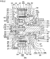
- FIG. 2 is a sectional view illustrating the front-right-tire-wheel-assembly driving apparatus 7 FR according to an embodiment of the invention. Because the front right tire-wheel assembly 2 FR and the front left tire-wheel assembly 2 FL have almost the same configuration, the configuration of the front right tire-wheel assembly 2 FR will be described by way of example, and description on the configuration of the front left tire-wheel assembly 2 FL will be omitted.
- the front-right-tire-wheel-assembly driving apparatus 7 FR includes an output shaft 31, the front-right-tire-wheel-assembly driving motor 6 FR , a speed-reducer 32, and a housing 33.
- the output shaft 31 is coupled to the wheel 4.
- the speed-reducer 32 reduces the speed of rotation output from the front-right-tire-wheel-assembly driving motor 6 FR , and transmits a rotary driving force generated by the front-right-tire-wheel-assembly driving motor 6 FR to the output shaft 31.
- the housing 33 accommodates the output shaft 31, the front-right-tire-wheel-assembly driving motor 6 FR , the speed-reducer 32, and so forth.
- axial direction the direction in which a central axis L of the output shaft 31 extends
- axial direction the direction toward the inside of the vehicle 1
- axially-outward direction the direction toward the outside of the vehicle 1
- the radial direction of the output shaft 31 will be simply referred to as "radial direction”.
- radial direction the direction toward the central axis L
- radially outward direction the direction away from the central axis L
- the housing 33 is made of a metal material containing, for example, aluminum.
- the housing 33 includes an annular portion 34 having an annular plate shape, a cylindrical portion 35 having a cylindrical shape, and a closing member 36 having an annular plate shape.
- the annular portion 34 is centered at the output shaft 31.
- the cylindrical portion 35 protrudes in the axially-inward direction from a peripheral edge of the annular portion 34, and opens on the opposite side of the housing 33 from the annular portion 34.
- the closing member 36 closes the opening of the cylindrical portion 35.
- the closing member 36 of the housing 33 is fastened to the cylindrical portion 35 with a bolt 37.
- the annular portion 34, the cylindrical portion 35, and the closing member 36 of the housing 33 define an internal space 38 in which the output shaft 31, the front-right-tire-wheel-assembly driving motor 6 FR , the speed-reducer 32, and so forth are accommodated.
- a first recess portion 34a and a second recess portion 34b are provided in the annular portion 34 of the housing 33.
- the first recess portion 34a is recessed in the axially-outward direction from an axially-inner-side surface of the annular portion 34.
- the second recess portion 34b is recessed in the axially-outward direction from the bottom of the first recess portion 34a.
- the second recess portion 34b has a radial width (opening width) that is smaller than the radial width (opening width) of the first recess portion 34a.
- a through-hole 34c extending through the second recess portion 34b in the axial direction is provided in the central portion of the bottom of the second recess portion 34b.
- the output shaft 31 has one end portion 31 a located on the axially-outer side and the other end portion 31b located on the axially-inner side.
- the one end portion 31a of the output shaft 31 passes through the annular portion 34 of the housing 33 (the through-hole 34c of the second recess portion 34b), and is located outside the housing 33.
- the other end portion 31b of the output shaft 31 is located in the internal space 38 of the housing 33.
- the output shaft 31 is supported by a hub bearing 39 provided in the housing 33 so as to be rotatable relative to the housing 33. The detailed configuration of the hub bearing 39 will be described later in detail.
- the front-right-tire-wheel-assembly driving motor 6 FR is an inner rotor motor.
- the front-right-tire-wheel-assembly driving motor 6 FR includes a stator 41 having an annular shape, a rotor 42 having an annular shape, and a motor shaft 43 having a columnar shape.
- the stator 41 is fixed to an inner peripheral surface of the cylindrical portion 35 of the housing 33.
- the rotor 42 having an annular shape is disposed radially inward of the stator 41.
- the motor shaft 43 is disposed radially inward of the rotor 42, and is coupled to the rotor 42.
- the stator 41 is fastened to the inner peripheral surface of the cylindrical portion 35 of the housing 33 with a bolt 44.
- the stator 41 is provided with stator coils including a U-phase coil, a V-phase coil, and a W-phase coil that respectively correspond to the U-phase, V-phase, and W-phase of the front-right-tire-wheel-assembly driving motor 6 FR .
- the motor shaft 43 is disposed coaxially with the output shaft 31.
- the motor shaft 43 has one end portion 43a located on the axially-outer side and the other end portion 43b located on the axially-inner side.
- the one end portion 43a of the motor shaft 43 is rotatably coupled to the other end portion 31b of the output shaft 31 via a bearing 45.
- the other end portion 43b of the motor shaft 43 extends through the closing member 36 of the housing 33, and is drawn outside the housing 33.
- the other end portion 43b of the motor shaft 43 is supported by a bearing 46 attached to an inner wall surface of the closing member 36 so as to be rotatable relative to the closing member 36.
- the motor shaft 43 is supported so as to be rotatable relative to the housing 33, and is rotatable relative to the output shaft 31.
- the rotor 42 is coupled to the motor shaft 43 via a coupling member 47.
- the coupling member 47 includes an annular portion 48 having an annular plate shape, a cylindrical portion 49, a flange portion 50, and a boss portion 51.
- the cylindrical portion 49 protrudes in a cylindrical shape in the axially-outward direction from a peripheral edge of the annular portion 48.
- the flange portion 50 protrudes in the radial direction from an axially-outer-side end portion of the cylindrical portion 49.
- the boss portion 51 extends toward one side in the axial direction (in the present embodiment, in the axially-outward direction) from an inner peripheral edge of the annular portion 48.
- the coupling member 47 is coupled to the motor shaft 43 so as to be rotatable together with the motor shaft 43 in an integrated manner, when the boss portion 51 is connected to the motor shaft 43 via a key 52.
- the rotor 42 is supported by the cylindrical portion 49 and the flange portion 50 of the coupling member 47. That is, the cylindrical portion 49 and the flange portion 50 of the coupling member 47 constitute a supporting portion that supports the rotor 42.
- the rotor 42 is fastened to the flange portion 50 with a bolt 53.
- the rotor 42 and the motor shaft 43 are coupled together via the coupling member 47 so as to be rotatable together with each other in an integrated manner.
- the motor shaft 43 is rotationally driven.
- the rotary driving force of the motor shaft 43 is transmitted to the speed-reducer 32.
- the speed-reducer 32 is disposed radially inward of the front-right-tire-wheel-assembly driving motor 6 FR . The speed-reducer 32 reduces the speed of rotation output from the motor shaft 43, and transmits the rotary driving force of the motor shaft 43 to the output shaft 31.
- the speed-reducer 32 includes a planetary gear mechanism 64 including a sun gear 60, a ring gear 61 having an annular shape, planet gears 62, and a carrier 63.
- the sun gear 60 is coupled to the one end portion 43a of the motor shaft 43 so as to be rotatable together with the motor shaft 43 in an integrated manner.
- the ring gear 61 is non-rotatably disposed around the sun gear 60.
- the planet gears 62 are disposed between the sun gear 60 and the ring gear 61 so as to be meshed with both the sun gear 60 and the ring gear 61.
- the carrier 63 is coupled to the output shaft 31 so as to be rotatable together with the output shaft 31 in an integrated manner.
- the carrier 63 holds the planet gears 62 so as to allow the planet gears 62 to rotate about their axes, and holds the planet gears 62 so as to allow the planet gears 62 to turn around the axis of the sun gear 60.
- the sun gear 60 is provided so as to be integral with the one end portion 43a of the motor shaft 43.
- the sun gear 60 is coupled to the rotor 42 via the motor shaft 43 and the coupling member 47 so as to be rotatable together with the rotor 42 in an integrated manner.
- the carrier 63 includes a carrier annular portion 65 having an annular plate shape. The carrier annular portion 65 is disposed apart from the output shaft 31 in the axially-outward direction, between the coupling member 47 of the front-right-tire-wheel-assembly driving motor 6 FR and the other end portion 31b of the output shaft 31.
- the carrier 63 is fixed to the output shaft 31 when the carrier annular portion 65 and the other end portion 31b of the output shaft 31 are fastened together with a bolt 66.
- Each of the planet gears 62 includes a planet gear shaft 67 and a gear portion 69.
- the planet gear shaft 67 is supported between the other end portion 31b of the output shaft 31 and the carrier annular portion 65.
- the gear portion 69 is rotatably supported by the planet gear shaft 67 via a bearing 68.
- the front-right-tire-wheel-assembly driving apparatus 7 FR further includes a ring-gear supporting member 71 having a generally cylindrical shape.
- the ring gear 61 is non-rotatably supported by the ring-gear supporting member 71.
- the ring gear 61 is fixed to the housing 33 via the ring-gear supporting member 71.
- the ring-gear supporting member 71 is preferably made of a metal material having a higher strength than that of the housing 33 (e.g., chrome molybdenum steel).
- the ring-gear supporting member 71 includes a first cylindrical portion 72, a second cylindrical portion 73 having a cylindrical shape, and a base portion 74 having an annular shape.
- the first cylindrical portion 72 is located on the axially-outer side, and is inserted in the second recess portion 34b of the annular portion 34 of the housing 33.
- the second cylindrical portion 73 is located on the axially-inner side, and extends through a region between the planet gears 62 and the rotor 42 (the cylindrical portion 49 of the coupling member 47) in the axial direction.
- the base portion 74 is connected to the first cylindrical portion 72 and the second cylindrical portion 73, at a position between the first cylindrical portion 72 and the second cylindrical portion 73.
- the first cylindrical portion 72 of the ring-gear supporting member 71 is inserted in the second recess portion 34b so as to come into contact with a side wall and a bottom wall of the second recess portion 34b of the annular portion 34 of the housing 33.
- the first cylindrical portion 72 of the ring-gear supporting member 71 has an inner peripheral surface that is flush with an inner peripheral surface of the base portion 74 of the ring-gear supporting member 71.
- the hub bearing 39 is disposed radially inward of the first cylindrical portion 72 and the base portion 74 of the ring-gear supporting member 71.
- the inner peripheral surfaces of the first cylindrical portion 72 and the base portion 74 of the ring-gear supporting member 71 constitute a bearing-supporting portion 75 that supports the hub bearing 39.
- the hub bearing 39 includes a double-row angular contact ball bearing.
- the hub bearing 39 includes an inner ring 76, an outer ring 77, and a plurality of rolling elements 78A, 78B.
- the rolling elements 78A, 78B are disposed between the inner ring 76 and the outer ring 77.
- the plurality of the rolling elements 78A, 78B includes a plurality of the first rolling elements 78A and a plurality of the second rolling elements 78B.
- the first rolling elements 78A are disposed on the axially-inner side, and are arranged along the circumferential direction of the inner ring 76 of the hub bearing 39.
- the second rolling elements 78B are disposed on the axially-outer side, and are arranged along the circumferential direction of the inner ring 76 of the hub bearing 39.
- the inner ring 76 of the hub bearing 39 is fitted to an outer peripheral surface of the output shaft 31 so as to be rotatable together with the output shaft 31 in an integrated manner.
- the output shaft 31 has a receiving portion 31c that is in contact with an axially-inner-side end portion of the inner ring 76 of the hub bearing 39, and receives the inner ring 76 of the hub bearing 39 in the axial direction.
- This receiving portion 31c of the output shaft 31 serves also as a positioning portion that sets the position at which the inner ring 76 of the hub bearing 39 is disposed.
- the outer ring 77 of the hub bearing 39 is non-rotatably supported by the bearing-supporting portion 75 of the ring-gear supporting member 71.
- the inner ring 76 is rotatably supported by the outer ring 77 of the hub bearing 39 via the rolling elements 78A, 78B. That is, the bearing-supporting portion 75 of the ring-gear supporting member 71 supports the output shaft 31 via the hub bearing 39 such that the output shaft 31 is rotatable.
- the second cylindrical portion 73 of the ring-gear supporting member 71 has an inner peripheral portion 73a facing the planet gears 62 at its axially-inner-side end portion, and supports the ring gear 61 at the inner peripheral portion 73a.
- the ring gear 61 is provided so as to be integral with the inner peripheral portion 73a of the second cylindrical portion 73. That is, the inner peripheral portion 73a of the second cylindrical portion 73 constitutes the ring gear-supporting portion 79 that supports the ring gear 61.
- the base portion 74 of the ring-gear supporting member 71 includes an outer annular protrusion 80 and an inner annular protrusion 81.
- the outer annular protrusion 80 protrudes in an annular shape radially outward from an outer peripheral surface of the base portion 74.
- the inner annular protrusion 81 protrudes in an annular shape radially inward from the inner peripheral surface of the base portion 74.
- the outer annular protrusion 80 of the base portion 74 is configured to be fitted in the first recess portion 34a of the housing 33, and is in contact with a side wall and a bottom wall of the first recess portion 34a.
- the outer annular protrusion 80 is fastened to the bottom portion of the first recess portion 34a with a bolt 82.
- a first bolt insertion hole 83 is selectively provided in the outer annular protrusion 80.
- a second bolt insertion hole 84 is provided in the bottom portion of the first recess portion 34a in the housing 33, at a position at which the second bolt insertion hole 84 is aligned with the first bolt insertion hole 83.
- the bolt 82 is inserted in the first bolt insertion hole 83 and the second bolt insertion hole 84 from the outer annular protrusion 80-side toward the annular portion 34 of the housing 33. In this way, the ring-gear supporting member 71 is fixed to the housing 33.
- the inner annular protrusion 81 of the base portion 74 is configured to protrude radially inward so as to come into contact with an axially-inner-side end portion of the hub bearing 39 in the axial direction.
- the inner annular protrusion 81 of the ring-gear supporting member 71 is in contact with at least the outer ring 77 of the hub bearing 39 in the axial direction.
- the inner annular protrusion 81 constitutes a load-receiving portion 85 configured to receive axial loads applied to the output shaft 31, via the hub bearing 39.
- the ring-gear supporting member 71 has, in addition to the function of fixing the ring gear 61 to the housing 33, the function of supporting the hub bearing 39 and the function of receiving axial loads applied to the output shaft 31, via the hub bearing 39.
- the ring-gear supporting member 71 is disposed in a region radially inward of the front-right-tire-wheel-assembly driving motor 6 FR and radially outward of the speed-reducer 32.
- the ring-gear supporting member 71 defines a first accommodation chamber 90 in which the front-right-tire-wheel-assembly driving motor 6 FR is accommodated and disposed.
- the first accommodation chamber 90 is disposed radially outward of the ring-gear supporting member 71.
- the ring-gear supporting member 71 defines a second accommodation chamber 91 in which the output shaft 31 and the speed-reducer 32 are accommodated and disposed.
- the second accommodation chamber 91 is disposed radially inward of the ring-gear supporting member 71. More specifically, the second accommodation chamber 91 is defined by a region surrounded by an inner wall surface of the ring-gear supporting member 71.
- the first accommodation chamber 90 is defined by a region interposed between an outer wall surface of the ring-gear supporting member 71 and an inner wall surface of the cylindrical portion 35 of the housing 33.
- the front-right-tire-wheel-assembly driving apparatus 7 FR may be assembled through the following steps. That is, first, the output shaft 31, the hub bearing 39, the planet gears 62, and so forth are installed in the second accommodation chamber 91 defined by the ring-gear supporting member 71, whereby an assembly unit in which these components are disposed in an integrated manner is formed (sub-assembly). Subsequently, the assembly unit (sub-assembly) is attached to the housing 33, and then the front-right-tire-wheel-assembly driving motor 6 FR is installed in the first accommodation chamber 90 defined between the housing 33 and the ring-gear supporting member 71. When the configuration in which the first accommodation chamber 90 and the second accommodation chamber 91 are defined in the housing 33 is employed, it becomes easier to install each of the constituent components that are accommodated and disposed in the housing 33.
- a wheel coupling member 95 to be coupled to the wheel 4 is attached to the one end portion 31 a of the output shaft 31 so as to be rotatable together with the output shaft 31 in an integrated manner.
- the wheel coupling member 95 includes a boss portion 97 having a cylindrical shape, and a flange portion 98 having an annular plate shape.
- the boss portion 97 is coupled to the one end portion 31a of the output shaft 31 through a key 96.
- the flange portion 98 extends radially outward from an axially-outer-side end portion of the boss portion 97.
- the flange portion 98 has a bolt insertion hole 100 through which the bolt 99 for attaching the wheel coupling member 95 to the wheel 4 is inserted.
- a seal member 101 is provided between the wheel coupling member 95 and the annular portion 34 of the housing 33.
- a nut 102 is screwed to the one end portion 31a of the output shaft 31, so that the wheel coupling member 95 is prevented from detaching from the output shaft 31.
- a rotation angle detection sensor 103 (in the present embodiment, a resolver) for detecting a rotation angle of the motor shaft 43 is attached to the other end portion 43b of the motor shaft 43.
- the speed-reducer 32 is disposed radially inward of the front-right-tire-wheel-assembly driving motor 6 FR .
- the speed-reducer 32 is disposed radially inward of the front-right-tire-wheel-assembly driving motor 6 FR .
- the first accommodation chamber 90 and the second accommodation chamber 91 are defined by the ring-gear supporting member 71, in the internal space 38 of the housing 33.
- the front-right-tire-wheel-assembly driving motor 6 FR is accommodated and disposed in the first accommodation chamber 90.
- the output shaft 31 and the speed-reducer 32 are accommodated and disposed in the second accommodation chamber 91.
- the ring-gear supporting member 71 for fixing the ring gear 61 to the housing 33 includes the bearing-supporting portion 75 (the first cylindrical portion 72 and the base portion 74 of the ring-gear supporting member 71) that supports the hub bearing 39, at a position between the output shaft 31 and the bearing-supporting portion 75.
- the ring-gear supporting member 71 includes the load-receiving portion 85 (the inner annular protrusion 81 of the base portion 74 of the ring-gear supporting member 71) for receiving axial loads applied to the output shaft 31, via the hub bearing 39.
- the axial loads applied to the output shaft 31 can be received by the load-receiving portion 85 of the ring-gear supporting member 71.
- the ring-gear supporting member 71 includes the load-receiving portion 85
- the load-receiving portion 85 can be formed using a part of the ring-gear supporting member 71.
- FIG. 3 is a sectional view illustrating a front-right-tire-wheel-assembly driving apparatus 7 FR according to another embodiment of the invention.
- the same configurations as those described with reference to FIG. 1 and FIG. 2 will be denoted by the same reference symbols as those in FIG. 1 and FIG. 2 , and description thereof will be omitted.
- an inner ring 76 of the hub bearing 39 includes a first portion 76A configured to support a plurality of the first rolling elements 78A and a second portion 76B configured to support a plurality of the second rolling elements 78B.
- the first portion 76A of the inner ring 76 is integral with the output shaft 31.
- the second portion 76B of the inner ring 76 is integral with the boss portion 97 of the wheel coupling member 95.
- the outer ring 77 of the hub bearing 39 is integral with the first cylindrical portion 72 and the base portion 74 of the ring-gear supporting member 71.
- the front-right-tire-wheel-assembly driving apparatus 7 FR it is possible to form the inner ring 76 of the hub bearing 39 using a part of the output shaft 31 and a part of the boss portion 97 of the wheel coupling member 95, and to form the outer ring 77 of the hub bearing 39 using a part of the ring-gear supporting member 71.
- the number of components is smaller than that in a case where the inner ring 76 and the outer ring 77 of the hub bearing 39 are individually provided. As a result, it becomes possible to achieve cost reduction.
- the front-right-tire-wheel-assembly driving motor 6 FR is an inner rotor motor.
- the front-right-tire-wheel-assembly driving motor 6 FR may be, instead of an inner rotor motor, an outer rotor motor including a stator 41 having an annular shape, and a rotor 42 having an annular shape and disposed radially outward of the stator 41.
- stator 41 is fixed to the ring-gear supporting member 71 (an outer peripheral surface of the second cylindrical portion 73) and the rotor 42 is disposed between the stator 41 and the inner wall surface of the cylindrical portion 35 of the housing 33.
- a driving apparatus having the same configuration as that of the driving apparatuses 7 FR , 9 FL may be installed in each of the rear right tire-wheel assembly 3 RR and the rear left tire-wheel assembly 3 RL .
- the boss portion 51 of the coupling member 47 may be spline-fitted to the motor shaft 43 without using the key 52, or may be serration-fitted to the motor shaft 43 without using the key 52.
- the boss portion 51 of the coupling member 47 may be fastened to the motor shaft 43 with a bolt, without using the key 52.
- the hub bearing 39 includes a double-row angular contact ball bearing.
- the hub bearing 39 may include, instead of a double-row angular contact ball bearing, a double-row tapered roller bearing. Further, it is possible to make a variety of design changes within the scope of the appended claims.
- the speed-reducer is disposed radially inward of the motor.
Abstract
A driving apparatus includes an output shaft, a driving motor, and a speed-reducer. The driving motor includes a stator having an annular shape, and a rotor having an annular shape. The rotor is disposed radially inward of the stator. The speed-reducer is disposed radially inward of the driving motor. The speed-reducer is configured to reduce the speed of rotation output from the rotor and transmit a rotary driving force of the rotor to the output shaft.
Description
- The invention relates to a driving apparatus and a tire-wheel assembly including the driving apparatus.
- There is a known driving apparatus configured such that the speed of rotation output from a motor is reduced by a speed-reducer and a rotary driving force generated by the motor is transmitted to a rotary shaft. Japanese Patent Application Publication No.
2016-97761 JP 2016-97761 A - The driving apparatus described in
JP 2016-97761 A - One object of the invention is to provide a driving apparatus configured to achieve desired size reduction thereof and a tire-wheel assembly including the driving apparatus.
- A driving apparatus according to an aspect of the invention includes an output shaft, a motor, and a speed-reducer. The motor includes a stator having an annular shape, and a rotor having an annular shape. The rotor is disposed radially inward of the stator or disposed radially outward of the stator. The speed-reducer is disposed radially inward of the motor. The speed-reducer is configured to reduce the speed of rotation output from the rotor and transmit a rotary driving force of the rotor to the output shaft.
- The foregoing and further features and advantages of the invention will become apparent from the following description of example embodiments with reference to the accompanying drawings, wherein like numerals are used to represent like elements and wherein:
-
FIG. 1 is a plan view schematically illustrating a drive-train of a vehicle; -
FIG. 2 is a sectional view illustrating a driving apparatus according to an embodiment of the invention; and -
FIG. 3 is a sectional view illustrating a driving apparatus according to another embodiment of the invention. - Hereinafter, example embodiments of the invention will be described in detail with reference to the accompanying drawings.
FIG. 1 is a plan view schematically illustrating a drive-train of avehicle 1. As illustrated inFIG. 1 , thevehicle 1 is a four-wheel-drive vehicle, and includes four tire-wheel assemblies including a pair of front tire-wheel assemblies 2FR, 2FL, and a pair of rear tire-wheel assemblies 3RR, 3RL. The pair of front tire-wheel assemblies 2FR, 2FL includes a front right tire-wheel assembly 2FR and a front left tire-wheel assembly 2FL. The pair of rear tire-wheel assemblies 3RR, 3RL includes a rear right tire-wheel assembly 3RR and a rear left tire-wheel assembly 3RL. Each of the front right tire-wheel assembly 2FR, the front left tire-wheel assembly 2FL, the rear right tire-wheel assembly 3RR, and the rear left tire-wheel assembly 3RL include awheel 4 and atire 5. - The front right tire-wheel assembly 2FR is rotationally driven by a front-right-tire-wheel-assembly driving apparatus 7FR including a front-right-tire-wheel-assembly driving motor 6FR (motor). The front left tire-wheel assembly 2FL is rotationally driven by a front-left-tire-wheel-assembly driving apparatus 9FL including a front-left-tire-wheel-assembly driving motor 8FL (motor). The front-right-tire-wheel-assembly driving motor 6FR is an in-wheel three-phase alternating-current (AC) electric motor incorporated in the
wheel 4 of the front right tire-wheel assembly 2FR. The front-left-tire-wheel-assembly driving motor 8FL is an in-wheel three-phase AC electric motor incorporated in thewheel 4 of the front left tire-wheel assembly 2FL. - The rear right tire-wheel assembly 3RR is rotationally driven by a rear-right-tire-wheel-assembly driving apparatus 11RR including a rear-right-tire-wheel-
assembly driving motor 100RR. The rear left tire-wheel assembly 3RL is rotationally driven by a rear-left-tire-wheel-assembly driving apparatus 13RL including a rear-left-tire-wheel-assembly driving motor 12RL. The rear-right-tire-wheel-assembly driving motor 10RR is an in-wheel three-phase AC electric motor incorporated in thewheel 4 of the rear right tire-wheel assembly 3RR. The rear-left-tire-wheel-assembly driving motor 12RL is an in-wheel three-phase AC electric motor incorporated in thewheel 4 of the rear left tire-wheel assembly 3RL. In the present embodiment, the rear right tire-wheel assembly 3RR and the rear left tire-wheel assembly 3RL have a direct-drive configuration, that is, the rear right tire-wheel assembly 3RR and the rear left tire-wheel assembly 3RL are rotationally driven directly by the rear-right-tire-wheel-assembly driving motor 10RR and the rear-left-tire-wheel-assembly driving motor 12RL, respectively. - The
vehicle 1 further includes asteering operation mechanism 14 configured to steer the front right tire-wheel assembly 2FR and the front left tire-wheel assembly 2FL. Thesteering operation mechanism 14 includes asteering wheel 15, asteering shaft 16, a first pinion shaft 17, a rack shaft 18, and twotie rods 19. Thesteering shaft 16 rotates in response to a steering operation of thesteering wheel 15. The first pinion shaft 17 is coupled to thesteering shaft 16 so as to rotate together with thesteering shaft 16 in an integrated manner. The first pinion shaft 17 hasfirst pinion teeth 17a. Thefirst pinion teeth 17a are meshed withfirst rack teeth 18a of the rack shaft 18. Thetie rods 19 are coupled to respective axial end portions of the rack shaft 18. The front right tire-wheel assembly 2FR and the front left tire-wheel assembly 2FL are coupled to the rack shaft 18 via thetie rods 19 and knuckle arms (not illustrated). - As the
steering wheel 15 is steered, the first pinion shaft 17 rotates together with thesteering shaft 16, and the rotation of the first pinion shaft 17 is converted into a reciprocating motion of the rack shaft 18. Thus, the steered angle of the front right tire-wheel assembly 2FR and the front left tire-wheel assembly 2FL changes, and the front right tire-wheel assembly 2FR and the front left tire-wheel assembly 2FL are steered. Thevehicle 1 further includes asteering assist mechanism 20 configured to apply a steering assist force to thesteering operation mechanism 14. Thesteering assist mechanism 20 includes asecond pinion shaft 21, asteering assist motor 22, and a steering assist speed-reducer 23. Thesecond pinion shaft 21 is rotationally driven by thesteering assist motor 22. The steering assist speed-reducer 23 reduces the speed of rotation output from thesteering assist motor 22, and transmits a rotary driving force generated by thesteering assist motor 22 to thesecond pinion shaft 21. Thesecond pinion shaft 21 hassecond pinion teeth 21 a. Thesecond pinion teeth 21 a are meshed withsecond rack teeth 18b of the rack shaft 18. - As the
steering assist motor 22 is driven, the speed of rotation output from thesteering assist motor 22 is reduced by the steering assist speed-reducer 23, and a rotary driving force generated by thesteering assist motor 22 is transmitted to thesecond pinion shaft 21. Thus, thesecond pinion shaft 21 rotates, and the rotation of thesecond pinion shaft 21 is converted into a reciprocating motion of the rack shaft 18. In this way, the steering assist force is applied to thesteering operation mechanism 14 by thesteering assist mechanism 20. - The
vehicle 1 further includes an electronic control unit (ECU) 24, aninverter module 25, and abattery 26. The ECU 24 is, for example, a microcomputer including a central processing unit (CPU) and memories (e.g., a read-only memory (ROM), a random-access memory (RAM), and a non-volatile memory). The ECU 24 controls the driving of the front-right-tire-wheel-assembly driving motor 6FR, the front-left-tire-wheel-assembly driving motor 8FL, the rear-right-tire-wheel-assembly driving motor 10RR, the rear-left-tire-wheel-assembly driving motor 12RL, and thesteering assist motor 22, via theinverter module 25. - The
inverter module 25 includes a plurality of three-phase inverter circuits configured to individually drive the front-right-tire-wheel-assembly driving motor 6FR, the front-left-tire-wheel-assembly driving motor 8FL, the rear-right-tire-wheel-assembly driving motor 10RR, the rear-left-tire-wheel-assembly driving motor 12RL, and thesteering assist motor 22. Theinverter module 25 drives the front-right-tire-wheel-assembly driving motor 6FR and the front-left-tire-wheel-assembly driving motor 8FL, with electric power supplied from thebattery 26. Thus, the front-right-tire-wheel-assembly driving motor 6FR and the front-left-tire-wheel-assembly driving motor 8FL are rotationally driven, so that the front right tire-wheel assembly 2FR and the front left tire-wheel assembly 2FL rotate. In addition, theinverter module 25 drives the rear-right-tire-wheel-assembly driving motor 10RR and the rear-left-tire-wheel-assembly driving motor 12RL, with electric power supplied from thebattery 26. Thus, the rear-right-tire-wheel-assembly driving motor 10RR and the rear-left-tire-wheel-assembly driving motor 12RL are rotationally driven, so that the rear right tire-wheel assembly 3RR and the rear left tire-wheel assembly 3RL rotate. In addition, theinverter module 25 drives the steering assistmotor 22, with electric power supplied from thebattery 26. Thus, a steering assist force is applied to thesteering operation mechanism 14. - Next, with reference to
FIG. 2 , the detailed configuration of the front-right-tire-wheel-assembly driving apparatus 7FR incorporated in thewheel 4 of the front right tire-wheel assembly 2FR will be described.FIG. 2 is a sectional view illustrating the front-right-tire-wheel-assembly driving apparatus 7FR according to an embodiment of the invention. Because the front right tire-wheel assembly 2FR and the front left tire-wheel assembly 2FL have almost the same configuration, the configuration of the front right tire-wheel assembly 2FR will be described by way of example, and description on the configuration of the front left tire-wheel assembly 2FL will be omitted. - With reference to
FIG. 2 , the front-right-tire-wheel-assembly driving apparatus 7FR includes anoutput shaft 31, the front-right-tire-wheel-assembly driving motor 6FR, a speed-reducer 32, and ahousing 33. Theoutput shaft 31 is coupled to thewheel 4. The speed-reducer 32 reduces the speed of rotation output from the front-right-tire-wheel-assembly driving motor 6FR, and transmits a rotary driving force generated by the front-right-tire-wheel-assembly driving motor 6FR to theoutput shaft 31. Thehousing 33 accommodates theoutput shaft 31, the front-right-tire-wheel-assembly driving motor 6FR, the speed-reducer 32, and so forth. - Hereinafter, the direction in which a central axis L of the
output shaft 31 extends will be simply referred to as "axial direction". In the axial direction, the direction toward the inside of thevehicle 1 will be simply referred to as "axially-inward direction", and the direction toward the outside of thevehicle 1 will be simply referred to as "axially-outward direction". The radial direction of theoutput shaft 31 will be simply referred to as "radial direction". In the radial direction, the direction toward the central axis L will be simply referred to as "radially inward direction", and the direction away from the central axis L will be simply referred to as "radially outward direction". - The
housing 33 is made of a metal material containing, for example, aluminum. Thehousing 33 includes anannular portion 34 having an annular plate shape, acylindrical portion 35 having a cylindrical shape, and a closingmember 36 having an annular plate shape. Theannular portion 34 is centered at theoutput shaft 31. Thecylindrical portion 35 protrudes in the axially-inward direction from a peripheral edge of theannular portion 34, and opens on the opposite side of thehousing 33 from theannular portion 34. The closingmember 36 closes the opening of thecylindrical portion 35. The closingmember 36 of thehousing 33 is fastened to thecylindrical portion 35 with abolt 37. Theannular portion 34, thecylindrical portion 35, and the closingmember 36 of thehousing 33 define aninternal space 38 in which theoutput shaft 31, the front-right-tire-wheel-assembly driving motor 6FR, the speed-reducer 32, and so forth are accommodated. - A
first recess portion 34a and asecond recess portion 34b are provided in theannular portion 34 of thehousing 33. Thefirst recess portion 34a is recessed in the axially-outward direction from an axially-inner-side surface of theannular portion 34. Thesecond recess portion 34b is recessed in the axially-outward direction from the bottom of thefirst recess portion 34a. Thesecond recess portion 34b has a radial width (opening width) that is smaller than the radial width (opening width) of thefirst recess portion 34a. A through-hole 34c extending through thesecond recess portion 34b in the axial direction is provided in the central portion of the bottom of thesecond recess portion 34b. - The
output shaft 31 has oneend portion 31 a located on the axially-outer side and theother end portion 31b located on the axially-inner side. The oneend portion 31a of theoutput shaft 31 passes through theannular portion 34 of the housing 33 (the through-hole 34c of thesecond recess portion 34b), and is located outside thehousing 33. Theother end portion 31b of theoutput shaft 31 is located in theinternal space 38 of thehousing 33. Theoutput shaft 31 is supported by a hub bearing 39 provided in thehousing 33 so as to be rotatable relative to thehousing 33. The detailed configuration of the hub bearing 39 will be described later in detail. - In the present embodiment, the front-right-tire-wheel-assembly driving motor 6FR is an inner rotor motor. The front-right-tire-wheel-assembly driving motor 6FR includes a
stator 41 having an annular shape, arotor 42 having an annular shape, and amotor shaft 43 having a columnar shape. Thestator 41 is fixed to an inner peripheral surface of thecylindrical portion 35 of thehousing 33. Therotor 42 having an annular shape is disposed radially inward of thestator 41. Themotor shaft 43 is disposed radially inward of therotor 42, and is coupled to therotor 42. Thestator 41 is fastened to the inner peripheral surface of thecylindrical portion 35 of thehousing 33 with abolt 44. Thestator 41 is provided with stator coils including a U-phase coil, a V-phase coil, and a W-phase coil that respectively correspond to the U-phase, V-phase, and W-phase of the front-right-tire-wheel-assembly driving motor 6FR. - The
motor shaft 43 is disposed coaxially with theoutput shaft 31. Themotor shaft 43 has oneend portion 43a located on the axially-outer side and theother end portion 43b located on the axially-inner side. The oneend portion 43a of themotor shaft 43 is rotatably coupled to theother end portion 31b of theoutput shaft 31 via a bearing 45. Theother end portion 43b of themotor shaft 43 extends through the closingmember 36 of thehousing 33, and is drawn outside thehousing 33. Theother end portion 43b of themotor shaft 43 is supported by a bearing 46 attached to an inner wall surface of the closingmember 36 so as to be rotatable relative to the closingmember 36. Thus, themotor shaft 43 is supported so as to be rotatable relative to thehousing 33, and is rotatable relative to theoutput shaft 31. - In the present embodiment, the
rotor 42 is coupled to themotor shaft 43 via acoupling member 47. More specifically, thecoupling member 47 includes anannular portion 48 having an annular plate shape, acylindrical portion 49, aflange portion 50, and aboss portion 51. Thecylindrical portion 49 protrudes in a cylindrical shape in the axially-outward direction from a peripheral edge of theannular portion 48. Theflange portion 50 protrudes in the radial direction from an axially-outer-side end portion of thecylindrical portion 49. Theboss portion 51 extends toward one side in the axial direction (in the present embodiment, in the axially-outward direction) from an inner peripheral edge of theannular portion 48. - The
coupling member 47 is coupled to themotor shaft 43 so as to be rotatable together with themotor shaft 43 in an integrated manner, when theboss portion 51 is connected to themotor shaft 43 via a key 52. Therotor 42 is supported by thecylindrical portion 49 and theflange portion 50 of thecoupling member 47. That is, thecylindrical portion 49 and theflange portion 50 of thecoupling member 47 constitute a supporting portion that supports therotor 42. In the present embodiment, therotor 42 is fastened to theflange portion 50 with abolt 53. Thus, therotor 42 is prevented from being detached from thecoupling member 47. Therotor 42 and themotor shaft 43 are coupled together via thecoupling member 47 so as to be rotatable together with each other in an integrated manner. - In the front-right-tire-wheel-assembly driving motor 6FR, as the
rotor 42 is rotationally driven, a rotary driving force of therotor 42 is transmitted to themotor shaft 43 via thecoupling member 47. Thus, themotor shaft 43 is rotationally driven. As themotor shaft 43 is rotationally driven, the rotary driving force of themotor shaft 43 is transmitted to the speed-reducer 32. The speed-reducer 32 is disposed radially inward of the front-right-tire-wheel-assembly driving motor 6FR. The speed-reducer 32 reduces the speed of rotation output from themotor shaft 43, and transmits the rotary driving force of themotor shaft 43 to theoutput shaft 31. In the present embodiment, the speed-reducer 32 includes a planetary gear mechanism 64 including asun gear 60, aring gear 61 having an annular shape, planet gears 62, and acarrier 63. Thesun gear 60 is coupled to the oneend portion 43a of themotor shaft 43 so as to be rotatable together with themotor shaft 43 in an integrated manner. Thering gear 61 is non-rotatably disposed around thesun gear 60. The planet gears 62 are disposed between thesun gear 60 and thering gear 61 so as to be meshed with both thesun gear 60 and thering gear 61. Thecarrier 63 is coupled to theoutput shaft 31 so as to be rotatable together with theoutput shaft 31 in an integrated manner. Thecarrier 63 holds the planet gears 62 so as to allow the planet gears 62 to rotate about their axes, and holds the planet gears 62 so as to allow the planet gears 62 to turn around the axis of thesun gear 60. - In the present embodiment, the
sun gear 60 is provided so as to be integral with the oneend portion 43a of themotor shaft 43. Thesun gear 60 is coupled to therotor 42 via themotor shaft 43 and thecoupling member 47 so as to be rotatable together with therotor 42 in an integrated manner. Thecarrier 63 includes a carrierannular portion 65 having an annular plate shape. The carrierannular portion 65 is disposed apart from theoutput shaft 31 in the axially-outward direction, between the couplingmember 47 of the front-right-tire-wheel-assembly driving motor 6FR and theother end portion 31b of theoutput shaft 31. Thecarrier 63 is fixed to theoutput shaft 31 when the carrierannular portion 65 and theother end portion 31b of theoutput shaft 31 are fastened together with abolt 66. Each of the planet gears 62 includes aplanet gear shaft 67 and agear portion 69. Theplanet gear shaft 67 is supported between theother end portion 31b of theoutput shaft 31 and the carrierannular portion 65. Thegear portion 69 is rotatably supported by theplanet gear shaft 67 via abearing 68. - The front-right-tire-wheel-assembly driving apparatus 7FR further includes a ring-
gear supporting member 71 having a generally cylindrical shape. Thering gear 61 is non-rotatably supported by the ring-gear supporting member 71. Thering gear 61 is fixed to thehousing 33 via the ring-gear supporting member 71. The ring-gear supporting member 71 is preferably made of a metal material having a higher strength than that of the housing 33 (e.g., chrome molybdenum steel). - The ring-
gear supporting member 71 includes a firstcylindrical portion 72, a secondcylindrical portion 73 having a cylindrical shape, and abase portion 74 having an annular shape. The firstcylindrical portion 72 is located on the axially-outer side, and is inserted in thesecond recess portion 34b of theannular portion 34 of thehousing 33. The secondcylindrical portion 73 is located on the axially-inner side, and extends through a region between the planet gears 62 and the rotor 42 (thecylindrical portion 49 of the coupling member 47) in the axial direction. Thebase portion 74 is connected to the firstcylindrical portion 72 and the secondcylindrical portion 73, at a position between the firstcylindrical portion 72 and the secondcylindrical portion 73. - The first
cylindrical portion 72 of the ring-gear supporting member 71 is inserted in thesecond recess portion 34b so as to come into contact with a side wall and a bottom wall of thesecond recess portion 34b of theannular portion 34 of thehousing 33. The firstcylindrical portion 72 of the ring-gear supporting member 71 has an inner peripheral surface that is flush with an inner peripheral surface of thebase portion 74 of the ring-gear supporting member 71. Thehub bearing 39 is disposed radially inward of the firstcylindrical portion 72 and thebase portion 74 of the ring-gear supporting member 71. The inner peripheral surfaces of the firstcylindrical portion 72 and thebase portion 74 of the ring-gear supporting member 71 constitute a bearing-supportingportion 75 that supports thehub bearing 39. Hereinafter, the configurations of theoutput shaft 31, the hub bearing 39, and the bearing-supportingportion 75 of the ring-gear supporting member 71 will be described in detail. - In the present embodiment, the hub bearing 39 includes a double-row angular contact ball bearing. The
hub bearing 39 includes aninner ring 76, anouter ring 77, and a plurality of rollingelements elements inner ring 76 and theouter ring 77. In the present embodiment, the plurality of the rollingelements first rolling elements 78A and a plurality of the secondrolling elements 78B. Thefirst rolling elements 78A are disposed on the axially-inner side, and are arranged along the circumferential direction of theinner ring 76 of thehub bearing 39. The secondrolling elements 78B are disposed on the axially-outer side, and are arranged along the circumferential direction of theinner ring 76 of thehub bearing 39. - The
inner ring 76 of the hub bearing 39 is fitted to an outer peripheral surface of theoutput shaft 31 so as to be rotatable together with theoutput shaft 31 in an integrated manner. In the present embodiment, theoutput shaft 31 has a receivingportion 31c that is in contact with an axially-inner-side end portion of theinner ring 76 of the hub bearing 39, and receives theinner ring 76 of the hub bearing 39 in the axial direction. This receivingportion 31c of theoutput shaft 31 serves also as a positioning portion that sets the position at which theinner ring 76 of the hub bearing 39 is disposed. - The
outer ring 77 of the hub bearing 39 is non-rotatably supported by the bearing-supportingportion 75 of the ring-gear supporting member 71. Theinner ring 76 is rotatably supported by theouter ring 77 of the hub bearing 39 via the rollingelements portion 75 of the ring-gear supporting member 71 supports theoutput shaft 31 via the hub bearing 39 such that theoutput shaft 31 is rotatable. The secondcylindrical portion 73 of the ring-gear supporting member 71 has an innerperipheral portion 73a facing the planet gears 62 at its axially-inner-side end portion, and supports thering gear 61 at the innerperipheral portion 73a. In the present embodiment, thering gear 61 is provided so as to be integral with the innerperipheral portion 73a of the secondcylindrical portion 73. That is, the innerperipheral portion 73a of the secondcylindrical portion 73 constitutes the ring gear-supportingportion 79 that supports thering gear 61. - The
base portion 74 of the ring-gear supporting member 71 includes an outerannular protrusion 80 and an innerannular protrusion 81. The outerannular protrusion 80 protrudes in an annular shape radially outward from an outer peripheral surface of thebase portion 74. The innerannular protrusion 81 protrudes in an annular shape radially inward from the inner peripheral surface of thebase portion 74. The outerannular protrusion 80 of thebase portion 74 is configured to be fitted in thefirst recess portion 34a of thehousing 33, and is in contact with a side wall and a bottom wall of thefirst recess portion 34a. The outerannular protrusion 80 is fastened to the bottom portion of thefirst recess portion 34a with abolt 82. More specifically, a firstbolt insertion hole 83 is selectively provided in the outerannular protrusion 80. In addition, a secondbolt insertion hole 84 is provided in the bottom portion of thefirst recess portion 34a in thehousing 33, at a position at which the secondbolt insertion hole 84 is aligned with the firstbolt insertion hole 83. Thebolt 82 is inserted in the firstbolt insertion hole 83 and the secondbolt insertion hole 84 from the outer annular protrusion 80-side toward theannular portion 34 of thehousing 33. In this way, the ring-gear supporting member 71 is fixed to thehousing 33. - The inner
annular protrusion 81 of thebase portion 74 is configured to protrude radially inward so as to come into contact with an axially-inner-side end portion of the hub bearing 39 in the axial direction. The innerannular protrusion 81 of the ring-gear supporting member 71 is in contact with at least theouter ring 77 of the hub bearing 39 in the axial direction. The innerannular protrusion 81 constitutes a load-receivingportion 85 configured to receive axial loads applied to theoutput shaft 31, via thehub bearing 39. - As described above, the ring-
gear supporting member 71 has, in addition to the function of fixing thering gear 61 to thehousing 33, the function of supporting the hub bearing 39 and the function of receiving axial loads applied to theoutput shaft 31, via thehub bearing 39. The ring-gear supporting member 71 is disposed in a region radially inward of the front-right-tire-wheel-assembly driving motor 6FR and radially outward of the speed-reducer 32. The ring-gear supporting member 71 defines afirst accommodation chamber 90 in which the front-right-tire-wheel-assembly driving motor 6FR is accommodated and disposed. Thefirst accommodation chamber 90 is disposed radially outward of the ring-gear supporting member 71. The ring-gear supporting member 71 defines asecond accommodation chamber 91 in which theoutput shaft 31 and the speed-reducer 32 are accommodated and disposed. Thesecond accommodation chamber 91 is disposed radially inward of the ring-gear supporting member 71. More specifically, thesecond accommodation chamber 91 is defined by a region surrounded by an inner wall surface of the ring-gear supporting member 71. Thefirst accommodation chamber 90 is defined by a region interposed between an outer wall surface of the ring-gear supporting member 71 and an inner wall surface of thecylindrical portion 35 of thehousing 33. - When configuration in which the
first accommodation chamber 90 and thesecond accommodation chamber 91 are defined is employed, the front-right-tire-wheel-assembly driving apparatus 7FR may be assembled through the following steps. That is, first, theoutput shaft 31, the hub bearing 39, the planet gears 62, and so forth are installed in thesecond accommodation chamber 91 defined by the ring-gear supporting member 71, whereby an assembly unit in which these components are disposed in an integrated manner is formed (sub-assembly). Subsequently, the assembly unit (sub-assembly) is attached to thehousing 33, and then the front-right-tire-wheel-assembly driving motor 6FR is installed in thefirst accommodation chamber 90 defined between thehousing 33 and the ring-gear supporting member 71. When the configuration in which thefirst accommodation chamber 90 and thesecond accommodation chamber 91 are defined in thehousing 33 is employed, it becomes easier to install each of the constituent components that are accommodated and disposed in thehousing 33. - Referring to
FIG. 2 again, outside thehousing 33, awheel coupling member 95 to be coupled to thewheel 4 is attached to the oneend portion 31 a of theoutput shaft 31 so as to be rotatable together with theoutput shaft 31 in an integrated manner. Thewheel coupling member 95 includes aboss portion 97 having a cylindrical shape, and aflange portion 98 having an annular plate shape. Theboss portion 97 is coupled to the oneend portion 31a of theoutput shaft 31 through a key 96. Theflange portion 98 extends radially outward from an axially-outer-side end portion of theboss portion 97. - The
flange portion 98 has abolt insertion hole 100 through which thebolt 99 for attaching thewheel coupling member 95 to thewheel 4 is inserted. Aseal member 101 is provided between thewheel coupling member 95 and theannular portion 34 of thehousing 33. Anut 102 is screwed to the oneend portion 31a of theoutput shaft 31, so that thewheel coupling member 95 is prevented from detaching from theoutput shaft 31. - Outside the
housing 33, a rotation angle detection sensor 103 (in the present embodiment, a resolver) for detecting a rotation angle of themotor shaft 43 is attached to theother end portion 43b of themotor shaft 43. When theoutput shaft 31 is rotationally driven with thewheel coupling member 95 coupled to thewheel 4, a rotary driving force of theoutput shaft 31 is transmitted to thewheel coupling member 95, so that thewheel coupling member 95 rotates. As thewheel coupling member 95 is rotationally driven, a rotary driving force of thewheel coupling member 95 is transmitted to thewheel 4, so that thewheel 4 rotates. In this way, the front right tire-wheel assembly 2FR rotates. - In the front-right-tire-wheel-assembly driving apparatus 7FR according to the present embodiment, the speed-reducer 32 is disposed radially inward of the front-right-tire-wheel-assembly driving motor 6FR. Thus, it is possible to appropriately reduce the axial width of the front-right-tire-wheel-assembly driving apparatus 7FR. Thus, it is possible to provide the front-right-tire-wheel-assembly driving apparatus 7FR configured to achieve desired size reduction thereof. In addition, in the front-right-tire-wheel-assembly driving apparatus 7FR according to the present embodiment, the
first accommodation chamber 90 and thesecond accommodation chamber 91 are defined by the ring-gear supporting member 71, in theinternal space 38 of thehousing 33. The front-right-tire-wheel-assembly driving motor 6FR is accommodated and disposed in thefirst accommodation chamber 90. Theoutput shaft 31 and the speed-reducer 32 are accommodated and disposed in thesecond accommodation chamber 91. Thus, it is possible to define each of the regions in which the front-right-tire-wheel-assembly driving motor 6FR, theoutput shaft 31, and the speed-reducer 32 are accommodated and disposed. Thus, it becomes easier to install the front-right-tire-wheel-assembly driving motor 6FR, theoutput shaft 31, and the speed-reducer 32 in thehousing 33. As a result, it becomes possible to achieve desired size reduction of the front-right-tire-wheel-assembly driving apparatus 7FR and increase the efficiency of producing the front-right-tire-wheel-assembly driving apparatus 7FR. - In the front-right-tire-wheel-assembly driving apparatus 7FR according to the present embodiment, the ring-
gear supporting member 71 for fixing thering gear 61 to thehousing 33 includes the bearing-supporting portion 75 (the firstcylindrical portion 72 and thebase portion 74 of the ring-gear supporting member 71) that supports the hub bearing 39, at a position between theoutput shaft 31 and the bearing-supportingportion 75. Thus, it is not necessary to use another member for supporting the hub bearing 39 between theoutput shaft 31 and the ring-gear supporting member 71, and thus the number of components can be reduced. As a result, it is possible to achieve further size reduction of the front-right-tire-wheel-assembly driving apparatus 7FR. - In addition, in the front-right-tire-wheel-assembly driving apparatus 7FR according to the present embodiment, the ring-
gear supporting member 71 includes the load-receiving portion 85 (the innerannular protrusion 81 of thebase portion 74 of the ring-gear supporting member 71) for receiving axial loads applied to theoutput shaft 31, via thehub bearing 39. With this configuration, the axial loads applied to theoutput shaft 31 can be received by the load-receivingportion 85 of the ring-gear supporting member 71. With the configuration in which the ring-gear supporting member 71 includes the load-receivingportion 85, it is possible to make the axial thickness of the load-receivingportion 85 smaller than that in a case where the load-receivingportion 85 is provided separately from the ring-gear supporting member 71. Furthermore, the load-receivingportion 85 can be formed using a part of the ring-gear supporting member 71. Thus, it is possible to reduce the number of components. As a result, it is possible to achieve further size reduction of the front-right-tire-wheel-assembly driving apparatus 7FR, from this viewpoint. -
FIG. 3 is a sectional view illustrating a front-right-tire-wheel-assembly driving apparatus 7FR according to another embodiment of the invention. InFIG. 3 , the same configurations as those described with reference toFIG. 1 andFIG. 2 will be denoted by the same reference symbols as those inFIG. 1 andFIG. 2 , and description thereof will be omitted. In the front-right-tire-wheel-assembly driving apparatus 7FR according to the present embodiment, aninner ring 76 of the hub bearing 39 includes afirst portion 76A configured to support a plurality of thefirst rolling elements 78A and asecond portion 76B configured to support a plurality of the secondrolling elements 78B. Thefirst portion 76A of theinner ring 76 is integral with theoutput shaft 31. Thesecond portion 76B of theinner ring 76 is integral with theboss portion 97 of thewheel coupling member 95. Theouter ring 77 of the hub bearing 39 is integral with the firstcylindrical portion 72 and thebase portion 74 of the ring-gear supporting member 71. - With this configuration as well, it is possible to exhibit the same effects as those described in the foregoing embodiment. In the front-right-tire-wheel-assembly driving apparatus 7FR according to the present embodiment, it is possible to form the
inner ring 76 of the hub bearing 39 using a part of theoutput shaft 31 and a part of theboss portion 97 of thewheel coupling member 95, and to form theouter ring 77 of the hub bearing 39 using a part of the ring-gear supporting member 71. Thus, in the front-right-tire-wheel-assembly driving apparatus 7FR according to the present embodiment, the number of components is smaller than that in a case where theinner ring 76 and theouter ring 77 of the hub bearing 39 are individually provided. As a result, it becomes possible to achieve cost reduction. - While the example embodiments of the invention have been described so far, the invention may be implemented in various other embodiments. For example, in each of the foregoing embodiments, the front-right-tire-wheel-assembly driving motor 6FR is an inner rotor motor. However, the front-right-tire-wheel-assembly driving motor 6FR may be, instead of an inner rotor motor, an outer rotor motor including a
stator 41 having an annular shape, and arotor 42 having an annular shape and disposed radially outward of thestator 41. When this configuration is employed, for example, thestator 41 is fixed to the ring-gear supporting member 71 (an outer peripheral surface of the second cylindrical portion 73) and therotor 42 is disposed between thestator 41 and the inner wall surface of thecylindrical portion 35 of thehousing 33. - In each of the foregoing embodiments, a driving apparatus having the same configuration as that of the driving apparatuses 7FR, 9FL may be installed in each of the rear right tire-wheel assembly 3RR and the rear left tire-wheel assembly 3RL. In addition, in each of the foregoing embodiments, the
boss portion 51 of thecoupling member 47 may be spline-fitted to themotor shaft 43 without using the key 52, or may be serration-fitted to themotor shaft 43 without using the key 52. Theboss portion 51 of thecoupling member 47 may be fastened to themotor shaft 43 with a bolt, without using the key 52. - In the foregoing embodiments, the hub bearing 39 includes a double-row angular contact ball bearing. Alternatively, the hub bearing 39 may include, instead of a double-row angular contact ball bearing, a double-row tapered roller bearing. Further, it is possible to make a variety of design changes within the scope of the appended claims.
- In the configuration of the invention, the speed-reducer is disposed radially inward of the motor. Thus, it is possible to appropriately reduce the axial width of the driving apparatus. As a result, it is possible to provide the driving apparatus configured to achieve desired size reduction thereof.
Claims (6)
- A driving apparatus comprising:an output shaft;a motor including a stator having an annular shape, and a rotor having an annular shape, the rotor being disposed radially inward of the stator or being disposed radially outward of the stator; anda speed-reducer disposed radially inward of the motor, the speed-reducer being configured to reduce a speed of rotation output from the rotor and transmit a rotary driving force of the rotor to the output shaft.
- The driving apparatus according to claim 1, wherein
the speed-reducer includes a planetary gear mechanism, and
the planetary gear mechanism includes:a sun gear coupled to the rotor so as to be rotatable together with the rotor in an integrated manner;a ring gear non-rotatably disposed around the sun gear;planet gears disposed between the sun gear and the ring gear so as to be meshed with both the sun gear and the ring gear; anda carrier coupled to the output shaft so as to be rotatable together with the output shaft in an integrated manner, the carrier being configured to hold the planet gears so as to allow the planet gears to rotate about axes of the planet gears, and the carrier being configured to hold the planet gears so as to allow the planet gears to turn around an axis of the sun gear. - The driving apparatus according to claim 2, further comprising:a ring-gear supporting member having a tubular shape, the ring-gear supporting member being configured to support the ring gear such that the ring gear is non-rotatable; anda housing configured to accommodate the output shaft and the motor, whereinthe ring-gear supporting member is attached to the housing so as to define a first chamber in which the motor is accommodated and so as to define a second chamber in which the output shaft and the speed-reducer are accommodated, the first chamber is disposed radially outward of the ring-gear supporting member, and the second chamber is disposed radially inward of the ring-gear supporting member.
- The driving apparatus according to claim 3, further comprising a bearing disposed between the output shaft and the ring-gear supporting member,
wherein the ring-gear supporting member includes a bearing-supporting portion configured to support the bearing, at a position between the output shaft and the ring-gear supporting portion. - The driving apparatus according to claim 4, wherein the ring-gear supporting member includes a load-receiving portion configured to receive an axial load applied to the output shaft, via the bearing.
- A tire-wheel assembly comprising:a wheel;a tire; andthe driving apparatus according to any one of claims 1 to 5, the driving apparatus being disposed in the wheel, and the driving apparatus being configured to transmit a rotary driving force of the output shaft to the wheel.
Applications Claiming Priority (1)
| Application Number | Priority Date | Filing Date | Title |
|---|---|---|---|
| JP2016118357A JP2017222251A (en) | 2016-06-14 | 2016-06-14 | Drive unit and wheel comprising the same |
Publications (1)
| Publication Number | Publication Date |
|---|---|
| EP3263384A1 true EP3263384A1 (en) | 2018-01-03 |
Family
ID=59055030
Family Applications (1)
| Application Number | Title | Priority Date | Filing Date |
|---|---|---|---|
| EP17175281.9A Withdrawn EP3263384A1 (en) | 2016-06-14 | 2017-06-09 | Driving apparatus and tire-wheel assembly including driving apparatus |
Country Status (4)
| Country | Link |
|---|---|
| US (1) | US20170355051A1 (en) |
| EP (1) | EP3263384A1 (en) |
| JP (1) | JP2017222251A (en) |
| CN (1) | CN107499112A (en) |
Families Citing this family (5)
| Publication number | Priority date | Publication date | Assignee | Title |
|---|---|---|---|---|
| CN111169274A (en) * | 2018-11-13 | 2020-05-19 | 舍弗勒技术股份两合公司 | In-wheel motor driving system and motor vehicle |
| EP3877581A4 (en) | 2019-01-17 | 2022-01-12 | Samsung Electronics Co., Ltd. | Washing machine |
| JP2020167827A (en) * | 2019-03-29 | 2020-10-08 | 日本電産株式会社 | motor |
| JP7192635B2 (en) * | 2019-04-16 | 2022-12-20 | 株式会社デンソー | rotary actuator |
| KR20230013858A (en) * | 2021-07-20 | 2023-01-27 | 현대모비스 주식회사 | Reaction torque apparatus of steering system for vehicle |
Citations (3)
| Publication number | Priority date | Publication date | Assignee | Title |
|---|---|---|---|---|
| US5382854A (en) * | 1992-07-29 | 1995-01-17 | Kabushikikaisha Equos Research | Electrical motor drive apparatus with planetary gearing |
| EP2762751A1 (en) * | 2011-09-27 | 2014-08-06 | NTN Corporation | In-wheel motor drive device |
| JP2016097761A (en) | 2014-11-20 | 2016-05-30 | Ntn株式会社 | In-wheel motor drive device |
-
2016
- 2016-06-14 JP JP2016118357A patent/JP2017222251A/en active Pending
-
2017
- 2017-06-06 US US15/614,981 patent/US20170355051A1/en not_active Abandoned
- 2017-06-09 EP EP17175281.9A patent/EP3263384A1/en not_active Withdrawn
- 2017-06-09 CN CN201710432142.9A patent/CN107499112A/en active Pending
Patent Citations (3)
| Publication number | Priority date | Publication date | Assignee | Title |
|---|---|---|---|---|
| US5382854A (en) * | 1992-07-29 | 1995-01-17 | Kabushikikaisha Equos Research | Electrical motor drive apparatus with planetary gearing |
| EP2762751A1 (en) * | 2011-09-27 | 2014-08-06 | NTN Corporation | In-wheel motor drive device |
| JP2016097761A (en) | 2014-11-20 | 2016-05-30 | Ntn株式会社 | In-wheel motor drive device |
Also Published As
| Publication number | Publication date |
|---|---|
| JP2017222251A (en) | 2017-12-21 |
| US20170355051A1 (en) | 2017-12-14 |
| CN107499112A (en) | 2017-12-22 |
Similar Documents
| Publication | Publication Date | Title |
|---|---|---|
| EP3263384A1 (en) | Driving apparatus and tire-wheel assembly including driving apparatus | |
| EP2148788B1 (en) | Wheel motor | |
| US7621835B2 (en) | In-wheel drive unit | |
| EP3357730B1 (en) | In-wheel motor drive device assembly | |
| JP4879191B2 (en) | High reduction ratio electric hub drive | |
| WO2014103556A1 (en) | Power-steering device | |
| EP2685129B1 (en) | Speed reduction mechanism and motor torque transmission apparatus including the same | |
| US20130057048A1 (en) | In-wheel motor driving device | |
| US20090101431A1 (en) | Steering apparatus for motor vehicle | |
| US10183692B2 (en) | Driving device | |
| JP2007078174A (en) | Power transmission device | |
| JP2009108947A (en) | Vehicle driving system | |
| JP2007159287A (en) | Motor support mechanism of drive unit for vehicle | |
| EP2778469B1 (en) | Wheel driving apparatus | |
| EP1990256B1 (en) | Electric power steering device | |
| US10821824B2 (en) | In-wheel motor drive device | |
| EP3428479A1 (en) | In-wheel motor drive device | |
| US11072364B2 (en) | Steering device | |
| US20140137678A1 (en) | Transmission ratio variable device | |
| JP2005212657A (en) | Motorized wheel driving device | |
| EP1031491A1 (en) | Improvements in or relating to vehicle steering | |
| CN217240462U (en) | Driving device and electric vehicle | |
| JP2015143069A (en) | electric power steering device | |
| WO2017026216A1 (en) | Motor driving device for vehicle | |
| CN210502249U (en) | In-wheel motor type vehicle drive apparatus |
Legal Events
| Date | Code | Title | Description |
|---|---|---|---|
| PUAI | Public reference made under article 153(3) epc to a published international application that has entered the european phase |
Free format text: ORIGINAL CODE: 0009012 |
|
| AK | Designated contracting states |
Kind code of ref document: A1 Designated state(s): AL AT BE BG CH CY CZ DE DK EE ES FI FR GB GR HR HU IE IS IT LI LT LU LV MC MK MT NL NO PL PT RO RS SE SI SK SM TR |
|
| AX | Request for extension of the european patent |
Extension state: BA ME |
|
| STAA | Information on the status of an ep patent application or granted ep patent |
Free format text: STATUS: THE APPLICATION IS DEEMED TO BE WITHDRAWN |
|
| 18D | Application deemed to be withdrawn |
Effective date: 20180704 |