EP3263371A1 - Axle device - Google Patents
Axle device Download PDFInfo
- Publication number
- EP3263371A1 EP3263371A1 EP17177602.4A EP17177602A EP3263371A1 EP 3263371 A1 EP3263371 A1 EP 3263371A1 EP 17177602 A EP17177602 A EP 17177602A EP 3263371 A1 EP3263371 A1 EP 3263371A1
- Authority
- EP
- European Patent Office
- Prior art keywords
- wheel drive
- drive case
- wheel
- pair
- coupling portion
- Prior art date
- Legal status (The legal status is an assumption and is not a legal conclusion. Google has not performed a legal analysis and makes no representation as to the accuracy of the status listed.)
- Granted
Links
Images


Classifications
-
- B—PERFORMING OPERATIONS; TRANSPORTING
- B62—LAND VEHICLES FOR TRAVELLING OTHERWISE THAN ON RAILS
- B62D—MOTOR VEHICLES; TRAILERS
- B62D7/00—Steering linkage; Stub axles or their mountings
- B62D7/06—Steering linkage; Stub axles or their mountings for individually-pivoted wheels, e.g. on king-pins
- B62D7/08—Steering linkage; Stub axles or their mountings for individually-pivoted wheels, e.g. on king-pins the pivotal axes being situated in a single plane transverse to the longitudinal centre line of the vehicle
-
- A—HUMAN NECESSITIES
- A01—AGRICULTURE; FORESTRY; ANIMAL HUSBANDRY; HUNTING; TRAPPING; FISHING
- A01B—SOIL WORKING IN AGRICULTURE OR FORESTRY; PARTS, DETAILS, OR ACCESSORIES OF AGRICULTURAL MACHINES OR IMPLEMENTS, IN GENERAL
- A01B69/00—Steering of agricultural machines or implements; Guiding agricultural machines or implements on a desired track
- A01B69/007—Steering or guiding of agricultural vehicles, e.g. steering of the tractor to keep the plough in the furrow
-
- B—PERFORMING OPERATIONS; TRANSPORTING
- B60—VEHICLES IN GENERAL
- B60B—VEHICLE WHEELS; CASTORS; AXLES FOR WHEELS OR CASTORS; INCREASING WHEEL ADHESION
- B60B35/00—Axle units; Parts thereof ; Arrangements for lubrication of axles
- B60B35/003—Steerable axles
-
- B—PERFORMING OPERATIONS; TRANSPORTING
- B60—VEHICLES IN GENERAL
- B60B—VEHICLE WHEELS; CASTORS; AXLES FOR WHEELS OR CASTORS; INCREASING WHEEL ADHESION
- B60B35/00—Axle units; Parts thereof ; Arrangements for lubrication of axles
- B60B35/12—Torque-transmitting axles
- B60B35/16—Axle housings
-
- B—PERFORMING OPERATIONS; TRANSPORTING
- B60—VEHICLES IN GENERAL
- B60G—VEHICLE SUSPENSION ARRANGEMENTS
- B60G9/00—Resilient suspensions of a rigid axle or axle housing for two or more wheels
- B60G9/02—Resilient suspensions of a rigid axle or axle housing for two or more wheels the axle or housing being pivotally mounted on the vehicle, e.g. the pivotal axis being parallel to the longitudinal axis of the vehicle
-
- B—PERFORMING OPERATIONS; TRANSPORTING
- B60—VEHICLES IN GENERAL
- B60K—ARRANGEMENT OR MOUNTING OF PROPULSION UNITS OR OF TRANSMISSIONS IN VEHICLES; ARRANGEMENT OR MOUNTING OF PLURAL DIVERSE PRIME-MOVERS IN VEHICLES; AUXILIARY DRIVES FOR VEHICLES; INSTRUMENTATION OR DASHBOARDS FOR VEHICLES; ARRANGEMENTS IN CONNECTION WITH COOLING, AIR INTAKE, GAS EXHAUST OR FUEL SUPPLY OF PROPULSION UNITS IN VEHICLES
- B60K17/00—Arrangement or mounting of transmissions in vehicles
- B60K17/22—Arrangement or mounting of transmissions in vehicles characterised by arrangement, location, or type of main drive shafting, e.g. cardan shaft
-
- B—PERFORMING OPERATIONS; TRANSPORTING
- B62—LAND VEHICLES FOR TRAVELLING OTHERWISE THAN ON RAILS
- B62D—MOTOR VEHICLES; TRAILERS
- B62D7/00—Steering linkage; Stub axles or their mountings
- B62D7/16—Arrangement of linkage connections
- B62D7/163—Arrangement of linkage connections substantially in axial direction, e.g. between rack bar and tie-rod
-
- B—PERFORMING OPERATIONS; TRANSPORTING
- B62—LAND VEHICLES FOR TRAVELLING OTHERWISE THAN ON RAILS
- B62D—MOTOR VEHICLES; TRAILERS
- B62D7/00—Steering linkage; Stub axles or their mountings
- B62D7/18—Steering knuckles; King pins
-
- B—PERFORMING OPERATIONS; TRANSPORTING
- B60—VEHICLES IN GENERAL
- B60G—VEHICLE SUSPENSION ARRANGEMENTS
- B60G2200/00—Indexing codes relating to suspension types
- B60G2200/30—Rigid axle suspensions
- B60G2200/32—Rigid axle suspensions pivoted
- B60G2200/322—Rigid axle suspensions pivoted with a single pivot point and a straight axle
-
- B—PERFORMING OPERATIONS; TRANSPORTING
- B60—VEHICLES IN GENERAL
- B60G—VEHICLE SUSPENSION ARRANGEMENTS
- B60G2200/00—Indexing codes relating to suspension types
- B60G2200/40—Indexing codes relating to the wheels in the suspensions
- B60G2200/422—Driving wheels or live axles
-
- B—PERFORMING OPERATIONS; TRANSPORTING
- B60—VEHICLES IN GENERAL
- B60G—VEHICLE SUSPENSION ARRANGEMENTS
- B60G2200/00—Indexing codes relating to suspension types
- B60G2200/40—Indexing codes relating to the wheels in the suspensions
- B60G2200/44—Indexing codes relating to the wheels in the suspensions steerable
-
- B—PERFORMING OPERATIONS; TRANSPORTING
- B60—VEHICLES IN GENERAL
- B60G—VEHICLE SUSPENSION ARRANGEMENTS
- B60G2206/00—Indexing codes related to the manufacturing of suspensions: constructional features, the materials used, procedures or tools
- B60G2206/01—Constructional features of suspension elements, e.g. arms, dampers, springs
- B60G2206/30—Constructional features of rigid axles
- B60G2206/31—Straight axle
-
- B—PERFORMING OPERATIONS; TRANSPORTING
- B60—VEHICLES IN GENERAL
- B60G—VEHICLE SUSPENSION ARRANGEMENTS
- B60G2206/00—Indexing codes related to the manufacturing of suspensions: constructional features, the materials used, procedures or tools
- B60G2206/01—Constructional features of suspension elements, e.g. arms, dampers, springs
- B60G2206/30—Constructional features of rigid axles
- B60G2206/32—Hollow cross section
-
- B—PERFORMING OPERATIONS; TRANSPORTING
- B60—VEHICLES IN GENERAL
- B60G—VEHICLE SUSPENSION ARRANGEMENTS
- B60G2206/00—Indexing codes related to the manufacturing of suspensions: constructional features, the materials used, procedures or tools
- B60G2206/01—Constructional features of suspension elements, e.g. arms, dampers, springs
- B60G2206/80—Manufacturing procedures
- B60G2206/81—Shaping
- B60G2206/8101—Shaping by casting
-
- B—PERFORMING OPERATIONS; TRANSPORTING
- B62—LAND VEHICLES FOR TRAVELLING OTHERWISE THAN ON RAILS
- B62D—MOTOR VEHICLES; TRAILERS
- B62D49/00—Tractors
-
- B—PERFORMING OPERATIONS; TRANSPORTING
- B62—LAND VEHICLES FOR TRAVELLING OTHERWISE THAN ON RAILS
- B62D—MOTOR VEHICLES; TRAILERS
- B62D7/00—Steering linkage; Stub axles or their mountings
- B62D7/16—Arrangement of linkage connections
Definitions
- the present invention relates to an axle device that improves stability of a work vehicle on inclined surfaces and/or reduces the risk of tipping or roll-over, and, when implemented in a farm tractor, can reduce the risk of tractor roll-over.
- the axle device described above mounts left and right wheels to the tractor vehicle body so as to be steerable and drivable, and also so as to enable rolling.
- An example of an axle device of this kind is provided in Japanese Patent Laid-open Publication No. 2001-086803 , for example.
- the axle device disclosed in Japanese Patent Laid-open Publication No. 2001-086803 includes a base end drive case (wheel drive case) and a wheel support body (wheel support).
- a coupling shaft (coupling portion) and an input shaft are provided at a middle portion of the base end drive case.
- the wheel drive case is coupled to a vehicle body in a state where an axis center of the input shaft is identical to a rolling axis center, and therefore a mounting height of the wheel drive case to the vehicle body is likely to be higher and a space between the wheel drive case and the vehicle body is likely to be narrower. In other words, a rise/fall range of the wheels is likely to be narrow. Also, a dual structure utilizing the coupling portion and a boss portion supporting the input shaft may be required, for example, and manufacture of the wheel drive case is likely to be difficult.
- the work vehicle is a tractor, for example.
- the wheel drive case is preferably configured to attach a pair of front wheels to the vehicle body of the work vehicle.
- the steering cylinder is preferably arranged outside of the wheel drive case. More preferably, the steering cylinder is preferably arranged on a front side of the wheel drive case with respect to the front-back direction of the work vehicle.
- the wheel drive case is preferably a cast member having a removable cover located on a side of the front wheel drive case.
- the input shaft is preferably oriented toward a rear of the work vehicle.
- the input shaft is oriented toward a rear of the work vehicle, in use.
- the front and rear coupling portions protrude above the top surface of the wheel drive case so as to be pivotally supported by a body frame of the vehicle body, in use.
- the wheel drive case pivots relative to the body frame about the rolling axis.
- the pivoting movement can maintain the lateral direction of the vehicle body horizontal irrespective of the angle of a wheel axis of the pair of wheels to the lateral direction of the vehicle body.
- the rolling axis center is positioned above the input shaft. Therefore, a vertical center of the wheel drive case can be positioned lower with respect to the rolling axis center.
- the rolling axis center and the input shaft are distributed in the vertical direction. Therefore, there is no need for a dual structure utilizing a coupling portion and a boss portion of the input shaft.
- the steering cylinder is positioned at an exterior portion of the wheel drive case. Therefore, inspection or the like of the steering cylinder can be performed while the steering cylinder remains supported by the wheel drive case.
- the steering cylinder is supported on the wheel drive case at a location within the vertical width of the center portion of the wheel drive case, below the coupling portion. Therefore, the steering cylinder can be brought closer to the wheel drive case and supported in the vertical direction as well as a front/back direction of the wheel drive case.
- the steering cylinder and wheel drive case can be assembled with the vehicle body in a single operation.
- the lower the vertical center of the wheel drive case is positioned relative to the rolling axis center, the more readily the space between the wheel drive case and the vehicle body can be enlarged, and the more readily the rise/fall range of the wheels can be enlarged.
- the wheels can be steered by the steering cylinder, and therefore the wheels can be steered with a minor operation of simply starting up the steering cylinder. In this way, easy steering of the vehicle body is enabled, and inspection or the like of the steering cylinder can also be readily performed while the steering cylinder remains supported by the wheel drive case.
- the steering cylinder in a state where the steering cylinder is brought close to the wheel drive case, the steering cylinder can be compactly assembled onto the vehicle body, and can be readily assembled together with the wheel drive case in a single operation.
- the front and rear coupling portions protrude above the top surface of the wheel drive case such that the axle device is pivotally supported by the body frame.
- the wheel drive case pivots relative to the body frame about a rolling axis extending along the front-back direction of the body frame.
- the pivoting movement maintains the lateral direction of the vehicle body independent from a wheel axis of the pair of front wheels. Accordingly, the vehicle body can be prompted to horizontally stay with respect to its lateral direction irrespective of the angle of the wheel axis to the lateral direction of the vehicle body.
- the body frame has two or more support members arranged along the rolling axis and are spaced away from each other. At least a front support member, which is arranged on the most front side, pivotably supports the front coupling portion about the rolling axis. At least a rear support member, which is arranged on the most rear side, pivotally supports the rear coupling portion about the rolling axis.
- At least one or more middle support members are arranged between the front and rear support members and pivotally support either the front or rear coupling portion.
- a wheel axis of a pair of front and/or rear wheels supported by the axle device is preferably located directly under the center of the middle support member.
- the load can be distributed on each of the front and rear coupling portions by adjusting the position of the middle support member and the wheel axis with respect to the font-back direction.
- the middle support member and the wheel axis are located slightly rearwards than the exact middle point between the front and rear support member, more load is distributed onto the rear coupling portion than the front coupling portion.
- the number of support members, the position of each support member, and the thickness of each support member are adjusted to realize a desired distribution of load on each support member.
- the front support member may be divided into two sub support members.
- the middle and rear support members may be formed as integral one support member.
- the front coupling portion is arranged forward of the body of the body of the axle device.
- the steering cylinder is located below the front coupling portion that is arranged forward of the body of the body of the axle device.
- the axle device preferably supports the pair of front wheels.
- a wheel axis of the rear wheels is integrally formed with the transmission mechanism. Thereby, the rear wheels, on which more load is applied than on the front wheels, are securely supported.
- a second aspect of the present invention provides an axle device comprising: a wheel drive case, a steerable left wheel support, a steerable right wheel support, a steering cylinder.
- the wheel drive case having: at least one centrally disposed vertically extending coupling portion; and an input shaft located below an upper end of the at least one coupling portion and being configured to transmit rotational power to wheels.
- the at least one coupling portion has a mounting opening configured to pivotally mount to the wheel drive case to a vehicle body of the work vehicle in a manner that allows the wheel drive case to pivot about an axis of the mounting opening.
- the axis when viewed from above, is at least one of:
- a third aspect of the present invention provides a four-wheel drive work vehicle having improved stability on inclined surfaces, comprising: an engine, a transmission, a front wheel drive case, a steerable left wheel support, a steerable right wheel support, and a steering cylinder.
- the front wheel drive case having: a centrally disposed vertically extending front coupling portion; a centrally disposed vertically extending rear coupling portion spaced from the front coupling portion; and a rear-facing input shaft located below an upper end of either the front or rear coupling portions and being configured to transmit rotational power to front wheels.
- the front and rear coupling portions are configured to pivotally mount to the front wheel drive case to a vehicle body of the work vehicle in a manner that allows the front wheel drive case to pivot about a main front to back vehicle axis.
- the steerable left wheel support is mounted to a left outer end of the front wheel drive case via a king pin and being configured to receive a work vehicle wheel.
- the steerable right wheel support is mounted to a right outer end of the front wheel drive case via a king pin and being configured to receive a work vehicle wheel.
- the steering cylinder is mounted to a front outer side of the front wheel drive case.
- the steering cylinder has a center axis located at a vertical position, and the vertical position is between at least one of:
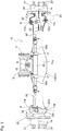
- Fig. 1 shows an overall left side view of a tractor type work vehicle.
- the tractor includes a pair of left and right front wheels 1 that are steerably and drivably mounted at a front of a vehicle body.
- a pair of left and right rear wheels 2 are drivably mounted at a rear portion of the vehicle body.
- the tractor is a four-wheel drive tractor.
- a motor system 3 is located in the front portion of the vehicle body.
- the motor system 3 includes an engine 4 (e.g., diesel engine) outputting drive power for the front wheels 1 and rear wheels 2.
- a cockpit 5 is utilize and is located toward the rear portion of the vehicle body.
- a cabin 6 can also be used to cover a riding space of the cockpit 5.
- a link mechanism or 3-point hitch 7 can extend rearward from the rear portion of the vehicle body so as to be capable of pivoting vertically.
- the tractor may be any of many types of riding-type work vehicles and can be configured to allow coupling thereto of various work apparatuses to the rear portion of the vehicle body such that a work apparatus that is capable of being lifted and lowered.
- the tractor may include a tiller apparatus, e.g., a rotary tilling device (not shown in the drawings) that is mounted to a rear portion of the vehicle body via the link mechanism 7 such that the rotary tilling device is capable of being lifted and lowered.
- a vehicle body frame F is utilized on the tractor along with the engine 4.
- a front frame 8 extends from the engine 4 toward the front of the vehicle body, and a transmission case 9 can be coupled to a front portion to a rear portion of the engine 4.
- a traveling transmission (not shown in the drawings) can be housed in the transmission case 9, with the traveling transmission transmitting drive power from the engine 4 to the front wheels 1 and the rear wheels 2.
- the left and right front wheels 1 are supported on the front frame 8 via an axle device 10.
- the axle device 10 includes a wheel drive case 11 supported at a center portion 11 a on the front frame 8.
- a pair of left and right wheel supports 20 are separately supported at each lateral end portion of the wheel drive case 11 and these supports 20 support the front wheels 1.
- an input shaft 12 is located at a rear vertical wall 11 r (corresponding to a rear portion) of the center portion 11 a of the case 11.
- the input shaft 12 is oriented in a front/back direction of the vehicle body and projects rearward or is rear-facing.
- a boss portion 13a of the case 11 supports the input shaft 12 and can be integrally formed with a lid, cover portion or cover 13.
- the cover 13 can be a separate member from a drive case main body 11 A of the wheel drive case 11.
- the cover 13 can be removed and reinstalled on the drive case main body 11 A to allow for assembly, inspection, and the like of a front wheel differential mechanism (not shown in the drawings).
- the cover 13 can be attached to and detached from the drive case main body 11 A via coupling bolts 14.
- the tractor uses a rotation shaft 17 coupled to an output shaft (not shown in the drawings) of a front wheel output portion 9a formed on a lower portion of the transmission case 9.
- the shaft 17 is coupled to the input shaft 12 and inputs front wheel drive power to the shaft 12 from the engine 4 and the transmission case 9.
- the input shaft 12 transmits power to the front wheel differential mechanism (not shown in the drawings) housed in the center portion 11 a.
- a coupling portion 15 (hereafter referred to as a front coupling portion or front mounting flange 15) stands upright, or extends or is oriented upward and forward, from a front vertical wall 11f (corresponding to a front portion) of the center portion 11 a.
- a coupling portion 16 (hereafter referred to as a rear coupling portion or rear mounting flange 16) stands upright, or extends or is oriented upward, from the rear vertical wall 11r (corresponding to the rear portion) of the center portion 11 a.
- the front coupling portion 15 and the rear coupling portion 16 extend up to a location further upward than a top surface 11 s of the center portion 11 a and the input shaft 12.
- the front coupling portion 15 can be integrally formed on the drive case main body 11 A by monobloc casting with the drive case main body 11 A.
- the rear coupling portion 16 can be integrally formed with the cover 13 by monobloc casting with the cover 13.
- the front coupling portion 15 and the rear coupling portion 16 are coupled to the front frame 8 so as to enable relative rotation or pivoting about a rolling axis center R, which is oriented in the front/back direction of the vehicle body, as a center of rotation.
- the front coupling portion 15 is coupled, so as to enable rotation or pivoting, via a coupling shaft 15a to a front-most support portion 8a of three support portions 8a, 8b, and 8c formed in a line on the front frame 8 at intervals in the front/back direction of the vehicle body.
- the rear coupling portion 16 is coupled, so as to enable rotation or pivoting, via a coupling shaft 16a to the two rearward support portions 8b and 8c of the three support portions 8a, 8b, and 8c.
- mounting axes or openings of portions 8a, 8b and 8c are coaxially aligned.
- the left and right wheel supports 20 provide support on lateral end portions of the wheel drive case 11, with the wheel supports 20 providing support enabling pivoting and steering around a steering axis center S, with S being the center or axis of steering rotation.
- the wheel supports 20 include a wheel drive portion 21 that rotates and drivably supports the front wheels 1.
- a steering support 22 supports the wheel drive portion 21 on the wheel drive case 11 so as to enable steering and pivoting.
- the steering support 22 includes a case-side coupling portion 22a coupled to a king pin 11 k so as to enable relative rotation or pivoting.
- the king pin 11 k is arranged on two vertical sides of the lateral end portions of the wheel drive case 11.
- a cylindrical support end portion 22b is housed and engaged so as to enable relative rotation in a cylindrical end portion 21 a of the wheel drive portion 21.
- the steering support 22 is supported on the wheel drive case 11 so as to enable steering and pivoting around the steering axis center S of the king pin 11 k as a pivot point.
- the steering axis center S is generally oriented in a vertical direction of the vehicle body and can be angled slightly as shown in Fig. 3 .
- the wheel drive portion 21 supports the front wheel 1 so as to enable integral rotation by having a rim portion of the front wheel 1 fixed or connected by a plurality of coupling bolts 23 to an end portion of the wheel drive portion 21 on an opposite side from the steering support 22.
- a deceleration mechanism 24 having the form of a planetary gear can be mounted in an interior of the wheel drive portion 21.
- the wheel drive portion 21 is rotationally driven around an axle center 1 a (which functions as a center of rotation), with the wheel drive portion 21 rotating with respect to the wheel drive case 11 and the steering support 22. This rotation occurs via the drive power input to the deceleration mechanism 24 from the input shaft 12 via the front wheel differential mechanism (not shown in the drawings) and the rotation shaft 25 (see Fig. 3 ).
- the drive power is decelerated by the deceleration mechanism 24 and rotationally drives the front wheels 1.
- a universal coupling 25a can be used which enables pivoting and steering of the steering support 22 while maintaining drive power via the shaft 25.
- the wheel support 20 is supported by the wheel drive case 11 in a state where the axle center 1 a is positioned between the front coupling portion 15 and the rear coupling portion 16, and closer to the rear coupling portion 16 than to the front coupling portion 15.
- a load distribution in which a ground-contact load of the front wheels 1 is split between the front coupling portion 15 and the rear coupling portion 16 an arrangement can be utilized where the axle center 1 a is positioned toward the rear coupling portion 16 in the present embodiment that manifests a load distribution of approximately 70% of the ground-contact load on the front wheels 1 being applied to the rear coupling portion 16.
- the load distribution may also be facilitated by arranging the front coupling 15 forward of the drive case.
- a steering cylinder 30 can be provided at a location on an exterior of the wheel drive case 11 below the front coupling portion 15.
- the steering cylinder 30 is arranged at a location within a vertical width of the center portion 11 a and is supported by a pair of left and right support members 31.
- the left and right support members 31 are configured to support or mount the steering cylinder 30 by mounting and engaging end portions of a cylinder portion of the steering cylinder 30.
- the left and right support members 31 can be at least partially integrally formed on the wheel drive case 11 by monobloc casting with the wheel drive case 11.
- a left end portion of a single cylinder rod 30a and one of the steering portions 22c are coupled by an interlocking rod 32, with the cylinder rod 30a coupled to the steering cylinder 30 and oriented in a lateral direction of the vehicle body.
- the steering portion 22c projects from the steering support 22 of the left front wheel 1 toward a side where the steering cylinder 30 is positioned.
- a right end portion of the cylinder rod 30a and the steering portion 22c, which projects from the steering support 22 of the right front wheel 1 toward a side where the steering cylinder 30 is positioned, are coupled by the interlocking rod 32.
- the steering portions 22c of the left and right front wheels 1 can be formed so as to be integral with the steering supports 22 by monobloc casting with the steering supports 22. In a state where the left and right interlocking rods 32 are positioned within the vertical width of the wheel drive case 11, the left and right interlocking rods 32 are provided spanning the cylinder rod 30a and the steering portions 22c.
- the wheel drive portion 21 of the left and right wheel supports 20 support the front wheels 1, in embodiments, so as to be incapable of relative rotation is rotatably supported on the wheel drive case 11 via the steering support 22.
- the front wheel drive power from the traveling transmission is transmitted to the deceleration mechanisms 24 via the rotation shaft 17, the input shaft 12, and the rotation shafts 25 and is decelerated.
- the wheel drive portions 21 is rotationally driven by the decelerated drive power. Therefore, the left and right front wheels 1 are rotationally driven around the axle center 1 a as the center of rotation.
- the wheel supports 20 supporting the left and right front wheels 1 are supported on the wheel drive case 11.
- the front coupling portion 15 and the rear coupling portion 16 are located at the center portion 11 a of the wheel drive case 11 are supported on the front frame 8 so as to be capable pivoting around the rolling axle center R as a center of pivoting.
- the wheel drive case 11 can thus be pivoted vertically with respect to the front frame 8 around the rolling axle center R as the center of pivoting. Therefore, the left and right front wheels 1 are capable of rolling movement with respect to the front frame 8.
- one of the left and right front wheels 1 can pivot down or up with respect to the vehicle body frame F around the rolling axis center R as the center of pivoting.
- the other of the left and right front wheels 1 will pivot up or down with respect to the vehicle body frame F around the rolling axis center R as the center of pivoting. This can occur while a posture of the vehicle body remains horizontal or substantially horizontal in the left/right direction. As such, the risk of roll-over is reduced.
- the wheel drive portion 21, of the left and right wheel supports 20, can support the front wheels 1 so as to be incapable of relative rotation and is supported on the wheel drive case 11 via the steering support 22 so as to enable steering and pivoting around the steering axis center S as the center of pivoting.
- the steering cylinder 30 is reciprocally coupled to the steering portion 22c of the left and right steering supports 22.
- a steering wheel 33 can be located in the cockpit 5 to control steering, also using a control valve (not shown in the drawings), of the steering cylinder 30. Accordingly, the left and right front wheels 1 can be steered and pivoted by the steering cylinder 30, and the vehicle body can be steered.
- the present invention is not limited to a tractor provided with front and rear wheels, and can also be applied to a tractor provided with a mini crawler instead of rear wheels.
Landscapes
- Engineering & Computer Science (AREA)
- Mechanical Engineering (AREA)
- Chemical & Material Sciences (AREA)
- Combustion & Propulsion (AREA)
- Transportation (AREA)
- Life Sciences & Earth Sciences (AREA)
- Soil Sciences (AREA)
- Environmental Sciences (AREA)
- Steering-Linkage Mechanisms And Four-Wheel Steering (AREA)
- Arrangement And Driving Of Transmission Devices (AREA)
- Vehicle Body Suspensions (AREA)
- Power Steering Mechanism (AREA)
Abstract
Description
- The present application claims priority of
Japanese Application No. 2016-126518, filed on June 27, 2016 - The present invention relates to an axle device that improves stability of a work vehicle on inclined surfaces and/or reduces the risk of tipping or roll-over, and, when implemented in a farm tractor, can reduce the risk of tractor roll-over.
- The axle device described above mounts left and right wheels to the tractor vehicle body so as to be steerable and drivable, and also so as to enable rolling. An example of an axle device of this kind is provided in
Japanese Patent Laid-open Publication No. 2001-086803 Japanese Patent Laid-open Publication No. 2001-086803 - When the conventional technology is adopted, the wheel drive case is coupled to a vehicle body in a state where an axis center of the input shaft is identical to a rolling axis center, and therefore a mounting height of the wheel drive case to the vehicle body is likely to be higher and a space between the wheel drive case and the vehicle body is likely to be narrower. In other words, a rise/fall range of the wheels is likely to be narrow. Also, a dual structure utilizing the coupling portion and a boss portion supporting the input shaft may be required, for example, and manufacture of the wheel drive case is likely to be difficult.
- Also, there is demand to provide a steering cylinder and to be able to steer a vehicle body by a minor operation of simply performing start-up of the steering cylinder.
- The above object is achieved by an axle device defined in the appended
claim 1. Further advantageous effects can be obtained by preferred embodiments defined in the appended dependent claims. - <1 > A first aspect of the present invention provides an axle device for a work vehicle, comprising: a wheel drive case having:
- a front coupling portion and rear coupling portion: configured to pivot relative to each other about a rolling axis, the rolling axis extending along a front-back direction of a vehicle body of the work vehicle, in use, and configured to be arranged at a center portion of the wheel drive case with respect to a lateral direction of the vehicle body, in use; and
- an input shaft configured to transmit rotational power to a pair of right-left wheels of the work vehicle, wherein
- the center portion includes a front portion and a rear portion,
- either one of the front portion and rear portion is provided with the input shaft, and
- the front coupling portion and rear coupling portion protrude above the input shaft, with respect to a vertical direction in use, from the front portion and the rear portion, respectively;
- a pair of wheel supports arranged on each outer end of the wheel drive case with respect to the lateral direction of the vehicle body and configured to support a pair of wheels for steering and pivoting; and
- a steering cylinder configured to steer the pair of wheel supports, the steering cylinder being supported by the wheel drive case to be located: below one of the front and rear coupling portions which is not provided with the input shaft, and within a width of the center portion of the wheel drive case with respect to the vertical direction, in use.
- The work vehicle is a tractor, for example.
- The wheel drive case is preferably configured to attach a pair of front wheels to the vehicle body of the work vehicle.
- The steering cylinder is preferably arranged outside of the wheel drive case. More preferably, the steering cylinder is preferably arranged on a front side of the wheel drive case with respect to the front-back direction of the work vehicle.
- The wheel drive case is preferably a cast member having a removable cover located on a side of the front wheel drive case.
- The input shaft is preferably oriented toward a rear of the work vehicle.
- The input shaft is oriented toward a rear of the work vehicle, in use.
- Preferably, the front and rear coupling portions protrude above the top surface of the wheel drive case so as to be pivotally supported by a body frame of the vehicle body, in use. Thereby, the wheel drive case pivots relative to the body frame about the rolling axis. The pivoting movement can maintain the lateral direction of the vehicle body horizontal irrespective of the angle of a wheel axis of the pair of wheels to the lateral direction of the vehicle body.
- According to this configuration, the rolling axis center is positioned above the input shaft. Therefore, a vertical center of the wheel drive case can be positioned lower with respect to the rolling axis center. The rolling axis center and the input shaft are distributed in the vertical direction. Therefore, there is no need for a dual structure utilizing a coupling portion and a boss portion of the input shaft.
- According to this configuration, the steering cylinder is positioned at an exterior portion of the wheel drive case. Therefore, inspection or the like of the steering cylinder can be performed while the steering cylinder remains supported by the wheel drive case. The steering cylinder is supported on the wheel drive case at a location within the vertical width of the center portion of the wheel drive case, below the coupling portion. Therefore, the steering cylinder can be brought closer to the wheel drive case and supported in the vertical direction as well as a front/back direction of the wheel drive case. The steering cylinder and wheel drive case can be assembled with the vehicle body in a single operation.
- Accordingly, in an axle device having a right-left wheels mounted to the vehicle body so as to be steerable and drivable, and also so as to enable rolling, the lower the vertical center of the wheel drive case is positioned relative to the rolling axis center, the more readily the space between the wheel drive case and the vehicle body can be enlarged, and the more readily the rise/fall range of the wheels can be enlarged. The wheels can be steered by the steering cylinder, and therefore the wheels can be steered with a minor operation of simply starting up the steering cylinder. In this way, easy steering of the vehicle body is enabled, and inspection or the like of the steering cylinder can also be readily performed while the steering cylinder remains supported by the wheel drive case. Furthermore, in a state where the steering cylinder is brought close to the wheel drive case, the steering cylinder can be compactly assembled onto the vehicle body, and can be readily assembled together with the wheel drive case in a single operation.
- <2> According a preferred embodiment of any one of the axle device mentioned above, an opening is formed on an outer surface of the wheel drive case; and the wheel drive case has a cover to open and close the opening.
- <3> According another preferred embodiment of any one of the axle device mentioned above, at least one of the front and rear coupling portions is integrally formed with the wheel drive case.
- <4> According a preferred embodiment of any one of the axle device mentioned above, one of the front coupling portion and the rear coupling portion, which is provided with the input shaft, is integrally formed with a cover of the wheel drive case to open and close a hole formed therein.
According to a further preferred embodiment of the present invention, the wheel drive case includes a cover formed with a boss portion and supporting the input shaft. The cover is capable of attaching to and detaching from the drive case main body. The coupling portion which rises from the one of the front portion and the rear portion to which the input shaft is provided is formed so as to be integral with the lidded case portion.
According to this configuration, the coupling portion on the input shaft side and the cover provided with the boss portion of the input shaft are formed so as to be integral. Thereby, a strength design of the boss portion can be freely modified. Moreover, because the cover is fixed or connected to the drive case, a number and size of a fixing pin, bolt, or the like can be readily adjusted. - <5> According a preferred embodiment of any one of the axle device mentioned above, one of the front coupling portion and the rear coupling portion, which is not provided with the input shaft, is integrally formed with a case body of the wheel drive case.
According to this configuration, the coupling portion on the opposite side from the input shaft side and the drive case main body are formed in a single operation, and thereby a degree of strength can be readily ensured and the coupling portion can be readily positioned on the vehicle body. - <6> According a preferred embodiment of any one of the axle device mentioned above, the wheel drive case further has a support member supporting the steering cylinder.
- <7> According a preferred embodiment of any one of the axle device mentioned above, the support member is integrally formed with the wheel drive case.
According to this configuration, the support member of the steering cylinder and the wheel drive case can be formed in a single operation. Therefore, as compared to a case where the members are formed separately and are coupled by a coupler such as a coupling bolt, a coupling seat or the like can be omitted and a projection length of the support member from the wheel drive case can be shortened. The steering cylinder can be supported closer to the wheel drive case. - <8> According a preferred embodiment of any one of the axle device mentioned above, each wheel support has: a wheel drive portion configured to support and drive a wheel; and a steering support pivotably supported by the wheel drive case and pivotably supporting the wheel drive portion.
The wheel drive portion supports the wheel so as not to pivot relative to each other.
The wheel drive portion and the steering support are pivotable relative to each other. - <9> According a preferred embodiment of any one of the axle device mentioned above, each wheel support has a projection configured to be connected to the steering cylinder.
- <10> According a preferred embodiment of any one of the axle device mentioned above, the steering cylinder is interlocked with the pair of wheel supports.
- <11> According a preferred embodiment of any one of the axle device mentioned above, the steering cylinder is coupled to the pair of wheel supports via an interlocking rod.
- <12> According a preferred embodiment of any one of the axle device mentioned above, the steering cylinder is interlocked with the pair of wheel supports at a position within a width of the wheel drive case with respect to the vertical direction, in use.
The axle device further comprises a pair of cylinder rods coupled to the steering cylinder on both end sides.
According to the configuration above, the steering support and the steering portion can be formed in a single operation. Therefore, as compared to a case where the members are formed separately and are coupled by a coupler such as a coupling bolt, a coupling seat or the like can be omitted and a projection length of the steering portion from the steering support can be shortened, and the interlocking rod can be supported closer to the steering support. The interlocking rod is positioned within the vertical width of the wheel drive case. Therefore, the interlocking rod can be supported on the steering portion in a state not protruding in the vertical direction from the wheel drive case. - <13> According a preferred embodiment of any one of the axle device mentioned above, in a view along a wheel axis of the pair of wheel support, the wheel axis is located at least one of: between the front coupling portion and rear coupling portion; and closer to one of the front or rear coupling portions which is provided with the input shaft than the other coupling portion.
According to another preferred embodiment of any one of the above-mentioned axle devices, the front coupling portion is preferably arranged on a front side of a body of the wheel drive case with respect to the front-back direction. Thereby, it is easier to adjust distribution of load on each of the front and rear coupling portions.
According to another preferred embodiment of any one of the above-mentioned axle devices, the thickness of each of the front and rear coupling portions with respect to the front-back direction is arrange so as to adjust distribution of load on the front and rear coupling portions.
According to the configuration above, a ground-contact load from the wheels on the input shaft-side coupling portion is larger than the ground-contact load on the coupling portion on the opposite side from the input shaft side. Therefore, the coupling portion on the input shaft side is readily supported by the support on the vehicle body side so as to be unlikely to rattle. - <14> According a preferred embodiment of any one of the axle device mentioned above, the rear portion of the wheel drive case is provided with the input shaft.
The input shaft is rear-facing. Such an axle device is preferably used for supporting a pair of front wheels of a work vehicle which has the pair of front wheels and a pair of rear wheels.
According to the configuration above, in the axle device that mounts left and right front wheels to the tractor vehicle body so as to be steerable and drivable, and also so as to enable rolling, the axle device facilitates enlarging the rise/fall range of the front wheels. The front wheels can be steered by the steering cylinder, and the vehicle body can be steered with a minor operation. Inspection or the like of the steering cylinder can also be readily performed while the steering cylinder remains supported by the wheel drive case. Furthermore, in a state where the steering cylinder is brought close to the wheel drive case, the steering cylinder can be compactly assembled onto the vehicle body, and can be assembled together with the wheel drive case in a single operation. - <15> A preferred embodiment of the present invention provides the work vehicle, comprising: an engine; a pair of front wheels and a pair of rear wheels; a transmission mechanism configured to transmit power from the engine to the front and rear wheels; a body frame accommodating the engine and the transmission mechanism, and supporting the pair of front wheels and the pair of rear wheels; and any one of the axle device mentioned-above pivotally supported by the body frame and supporting at least one of the pair of front wheels and the pair of rear wheels.
- Preferably, the front and rear coupling portions protrude above the top surface of the wheel drive case such that the axle device is pivotally supported by the body frame. Thereby, the wheel drive case pivots relative to the body frame about a rolling axis extending along the front-back direction of the body frame. The pivoting movement maintains the lateral direction of the vehicle body independent from a wheel axis of the pair of front wheels. Accordingly, the vehicle body can be prompted to horizontally stay with respect to its lateral direction irrespective of the angle of the wheel axis to the lateral direction of the vehicle body.
- Preferably, the body frame has two or more support members arranged along the rolling axis and are spaced away from each other. At least a front support member, which is arranged on the most front side, pivotably supports the front coupling portion about the rolling axis. At least a rear support member, which is arranged on the most rear side, pivotally supports the rear coupling portion about the rolling axis.
- Furthermore preferably, at least one or more middle support members are arranged between the front and rear support members and pivotally support either the front or rear coupling portion. When one middle support member is arranged, a wheel axis of a pair of front and/or rear wheels supported by the axle device is preferably located directly under the center of the middle support member. The load can be distributed on each of the front and rear coupling portions by adjusting the position of the middle support member and the wheel axis with respect to the font-back direction. When the middle support member and the wheel axis are located slightly rearwards than the exact middle point between the front and rear support member, more load is distributed onto the rear coupling portion than the front coupling portion.
- The number of support members, the position of each support member, and the thickness of each support member are adjusted to realize a desired distribution of load on each support member. For example, among the three of the front, middle and rear support members mentioned above, the front support member may be divided into two sub support members. Likewise, the middle and rear support members may be formed as integral one support member.
- Furthermore preferably, the front coupling portion is arranged forward of the body of the body of the axle device. Even furthermore preferably, the steering cylinder is located below the front coupling portion that is arranged forward of the body of the body of the axle device. Thereby, distribution of loads on the front and rear coupling portions can be easily adjusted.
- The axle device preferably supports the pair of front wheels. Preferably, a wheel axis of the rear wheels is integrally formed with the transmission mechanism. Thereby, the rear wheels, on which more load is applied than on the front wheels, are securely supported.
- A second aspect of the present invention provides an axle device comprising: a wheel drive case, a steerable left wheel support, a steerable right wheel support, a steering cylinder. The wheel drive case having: at least one centrally disposed vertically extending coupling portion; and an input shaft located below an upper end of the at least one coupling portion and being configured to transmit rotational power to wheels. The at least one coupling portion has a mounting opening configured to pivotally mount to the wheel drive case to a vehicle body of the work vehicle in a manner that allows the wheel drive case to pivot about an axis of the mounting opening. The axis, when viewed from above, is at least one of:
- parallel to a front to back direction of the vehicle body; and
- parallel to a centrally disposed front to back axis of the vehicle body.
- the upper end of the at least one coupling portion and a lower end of the wheel drive case;
- a lower end of the at least one coupling portion and a lower end of the wheel drive case;
- the upper end of the at least one coupling portion and a center axis of the input shaft; and
- the lower end of the at least one coupling portion and a center axis of the input shaft.
- A third aspect of the present invention provides a four-wheel drive work vehicle having improved stability on inclined surfaces, comprising: an engine, a transmission, a front wheel drive case, a steerable left wheel support, a steerable right wheel support, and a steering cylinder. The front wheel drive case having: a centrally disposed vertically extending front coupling portion; a centrally disposed vertically extending rear coupling portion spaced from the front coupling portion; and a rear-facing input shaft located below an upper end of either the front or rear coupling portions and being configured to transmit rotational power to front wheels. The front and rear coupling portions are configured to pivotally mount to the front wheel drive case to a vehicle body of the work vehicle in a manner that allows the front wheel drive case to pivot about a main front to back vehicle axis. The steerable left wheel support is mounted to a left outer end of the front wheel drive case via a king pin and being configured to receive a work vehicle wheel. The steerable right wheel support is mounted to a right outer end of the front wheel drive case via a king pin and being configured to receive a work vehicle wheel. The steering cylinder is mounted to a front outer side of the front wheel drive case.
- According to a preferred embodiment of the work vehicle above, the steering cylinder has a center axis located at a vertical position, and the vertical position is between at least one of:
- the upper end of the front coupling portion and a lower end of the front wheel drive case;
- the upper end of the rear coupling portion and a lower end of the front wheel drive case;
- the upper end of the front coupling portion and a center axis of the input shaft; and
- the upper end of the rear coupling portion and a center axis of the input shaft.
- The present invention is further described in the detailed description which follows, in reference to the noted plurality of drawings by way of non-limiting examples of exemplary embodiments of the present invention, in which like reference numerals represent similar parts throughout the several views of the drawings, and wherein:
-
Fig. 1 is an overall left side view of an exemplary tractor; -
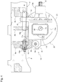
Fig. 2 is a perspective view illustrating an axle device; -
Fig. 3 is a front view illustrating an axle device; and -
Fig. 4 is a left side view illustrating a support structure of a wheel drive case. - The particulars shown herein are by way of example and for purposes of illustrative discussion of the embodiments of the present invention only and are presented in the cause of providing what is believed to be the most useful and readily understood description of the principles and conceptual aspects of the present invention. In this regard, no attempt is made to show structural details of the present invention in more detail than is necessary for the fundamental understanding of the present invention, the description taken with the drawings making apparent to those skilled in the art how the forms of the present invention may be embodied in practice.
- An embodiment of the present invention is described below with reference to the drawings.
Fig. 1 shows an overall left side view of a tractor type work vehicle. As shown inFig. 1 , the tractor includes a pair of left and rightfront wheels 1 that are steerably and drivably mounted at a front of a vehicle body. A pair of left and rightrear wheels 2 are drivably mounted at a rear portion of the vehicle body. Thus, in this example, the tractor is a four-wheel drive tractor. Amotor system 3 is located in the front portion of the vehicle body. Themotor system 3 includes an engine 4 (e.g., diesel engine) outputting drive power for thefront wheels 1 andrear wheels 2. Acockpit 5 is utilize and is located toward the rear portion of the vehicle body. Acabin 6 can also be used to cover a riding space of thecockpit 5. A link mechanism or 3-point hitch 7 can extend rearward from the rear portion of the vehicle body so as to be capable of pivoting vertically. - The tractor may be any of many types of riding-type work vehicles and can be configured to allow coupling thereto of various work apparatuses to the rear portion of the vehicle body such that a work apparatus that is capable of being lifted and lowered. For example, the tractor may include a tiller apparatus, e.g., a rotary tilling device (not shown in the drawings) that is mounted to a rear portion of the vehicle body via the
link mechanism 7 such that the rotary tilling device is capable of being lifted and lowered. - As shown in
Fig. 1 , a vehicle body frame F is utilized on the tractor along with the engine 4. Afront frame 8 extends from the engine 4 toward the front of the vehicle body, and atransmission case 9 can be coupled to a front portion to a rear portion of the engine 4. A traveling transmission (not shown in the drawings) can be housed in thetransmission case 9, with the traveling transmission transmitting drive power from the engine 4 to thefront wheels 1 and therear wheels 2. The left and rightfront wheels 1 are supported on thefront frame 8 via anaxle device 10. - As shown in
Figs. 2 and3 , theaxle device 10 includes awheel drive case 11 supported at acenter portion 11 a on thefront frame 8. A pair of left and right wheel supports 20 are separately supported at each lateral end portion of thewheel drive case 11 and thesesupports 20 support thefront wheels 1. - As shown in
Figs. 2 to 4 , aninput shaft 12 is located at a rearvertical wall 11 r (corresponding to a rear portion) of thecenter portion 11 a of thecase 11. Theinput shaft 12 is oriented in a front/back direction of the vehicle body and projects rearward or is rear-facing. Aboss portion 13a of thecase 11 supports theinput shaft 12 and can be integrally formed with a lid, cover portion orcover 13. Thecover 13 can be a separate member from a drive casemain body 11 A of thewheel drive case 11. Thecover 13 can be removed and reinstalled on the drive casemain body 11 A to allow for assembly, inspection, and the like of a front wheel differential mechanism (not shown in the drawings). Thecover 13 can be attached to and detached from the drive casemain body 11 A viacoupling bolts 14. - As shown in
Fig. 1 , the tractor uses arotation shaft 17 coupled to an output shaft (not shown in the drawings) of a frontwheel output portion 9a formed on a lower portion of thetransmission case 9. Theshaft 17 is coupled to theinput shaft 12 and inputs front wheel drive power to theshaft 12 from the engine 4 and thetransmission case 9. Theinput shaft 12 transmits power to the front wheel differential mechanism (not shown in the drawings) housed in thecenter portion 11 a. - As shown in
Figs. 2 to 4 , a coupling portion 15 (hereafter referred to as a front coupling portion or front mounting flange 15) stands upright, or extends or is oriented upward and forward, from a frontvertical wall 11f (corresponding to a front portion) of thecenter portion 11 a. A coupling portion 16 (hereafter referred to as a rear coupling portion or rear mounting flange 16) stands upright, or extends or is oriented upward, from the rearvertical wall 11r (corresponding to the rear portion) of thecenter portion 11 a. Thefront coupling portion 15 and therear coupling portion 16 extend up to a location further upward than atop surface 11 s of thecenter portion 11 a and theinput shaft 12. Thefront coupling portion 15 can be integrally formed on the drive casemain body 11 A by monobloc casting with the drive casemain body 11 A. Therear coupling portion 16 can be integrally formed with thecover 13 by monobloc casting with thecover 13. - As shown in
Figs. 3 and4 , thefront coupling portion 15 and therear coupling portion 16 are coupled to thefront frame 8 so as to enable relative rotation or pivoting about a rolling axis center R, which is oriented in the front/back direction of the vehicle body, as a center of rotation. Specifically, thefront coupling portion 15 is coupled, so as to enable rotation or pivoting, via acoupling shaft 15a to afront-most support portion 8a of threesupport portions front frame 8 at intervals in the front/back direction of the vehicle body. Therear coupling portion 16 is coupled, so as to enable rotation or pivoting, via acoupling shaft 16a to the tworearward support portions support portions portions - As shown in
Figs. 2 and3 , the left and right wheel supports 20 provide support on lateral end portions of thewheel drive case 11, with the wheel supports 20 providing support enabling pivoting and steering around a steering axis center S, with S being the center or axis of steering rotation. Specifically, as shown inFigs. 2 and3 , the wheel supports 20 include awheel drive portion 21 that rotates and drivably supports thefront wheels 1. Asteering support 22 supports thewheel drive portion 21 on thewheel drive case 11 so as to enable steering and pivoting. - As shown in
Figs. 2 and3 , thesteering support 22 includes a case-side coupling portion 22a coupled to aking pin 11 k so as to enable relative rotation or pivoting. Theking pin 11 k is arranged on two vertical sides of the lateral end portions of thewheel drive case 11. A cylindricalsupport end portion 22b is housed and engaged so as to enable relative rotation in acylindrical end portion 21 a of thewheel drive portion 21. While supporting thewheel drive portion 21, so as to enable rotation, thesteering support 22 is supported on thewheel drive case 11 so as to enable steering and pivoting around the steering axis center S of theking pin 11 k as a pivot point. The steering axis center S is generally oriented in a vertical direction of the vehicle body and can be angled slightly as shown inFig. 3 . - The
wheel drive portion 21 supports thefront wheel 1 so as to enable integral rotation by having a rim portion of thefront wheel 1 fixed or connected by a plurality ofcoupling bolts 23 to an end portion of thewheel drive portion 21 on an opposite side from thesteering support 22. Adeceleration mechanism 24 having the form of a planetary gear can be mounted in an interior of thewheel drive portion 21. Thewheel drive portion 21 is rotationally driven around anaxle center 1 a (which functions as a center of rotation), with thewheel drive portion 21 rotating with respect to thewheel drive case 11 and thesteering support 22. This rotation occurs via the drive power input to thedeceleration mechanism 24 from theinput shaft 12 via the front wheel differential mechanism (not shown in the drawings) and the rotation shaft 25 (seeFig. 3 ). The drive power is decelerated by thedeceleration mechanism 24 and rotationally drives thefront wheels 1. As shown inFig. 3 , auniversal coupling 25a can be used which enables pivoting and steering of thesteering support 22 while maintaining drive power via theshaft 25. - In a state where the
front wheel 1 is steered for straight-line travel (for example), in a view along theaxle center 1 a, as shown inFig. 4 , thewheel support 20 is supported by thewheel drive case 11 in a state where theaxle center 1 a is positioned between thefront coupling portion 15 and therear coupling portion 16, and closer to therear coupling portion 16 than to thefront coupling portion 15. As an example of a load distribution in which a ground-contact load of thefront wheels 1 is split between thefront coupling portion 15 and therear coupling portion 16, an arrangement can be utilized where theaxle center 1 a is positioned toward therear coupling portion 16 in the present embodiment that manifests a load distribution of approximately 70% of the ground-contact load on thefront wheels 1 being applied to therear coupling portion 16. Though adjustments to thickness of thecoupling portions front coupling 15 forward of the drive case. - As shown in
Figs. 2 to 4 , asteering cylinder 30 can be provided at a location on an exterior of thewheel drive case 11 below thefront coupling portion 15. Thesteering cylinder 30 is arranged at a location within a vertical width of thecenter portion 11 a and is supported by a pair of left andright support members 31. The left andright support members 31 are configured to support or mount thesteering cylinder 30 by mounting and engaging end portions of a cylinder portion of thesteering cylinder 30. The left andright support members 31 can be at least partially integrally formed on thewheel drive case 11 by monobloc casting with thewheel drive case 11. A left end portion of asingle cylinder rod 30a and one of thesteering portions 22c are coupled by an interlockingrod 32, with thecylinder rod 30a coupled to thesteering cylinder 30 and oriented in a lateral direction of the vehicle body. Thesteering portion 22c projects from thesteering support 22 of the leftfront wheel 1 toward a side where thesteering cylinder 30 is positioned. A right end portion of thecylinder rod 30a and thesteering portion 22c, which projects from thesteering support 22 of the rightfront wheel 1 toward a side where thesteering cylinder 30 is positioned, are coupled by the interlockingrod 32. As shown inFig. 3 , thesteering portions 22c of the left and rightfront wheels 1 can be formed so as to be integral with the steering supports 22 by monobloc casting with the steering supports 22. In a state where the left and right interlockingrods 32 are positioned within the vertical width of thewheel drive case 11, the left and right interlockingrods 32 are provided spanning thecylinder rod 30a and thesteering portions 22c. - The
wheel drive portion 21 of the left and right wheel supports 20 support thefront wheels 1, in embodiments, so as to be incapable of relative rotation is rotatably supported on thewheel drive case 11 via thesteering support 22. The front wheel drive power from the traveling transmission is transmitted to thedeceleration mechanisms 24 via therotation shaft 17, theinput shaft 12, and therotation shafts 25 and is decelerated. Thewheel drive portions 21 is rotationally driven by the decelerated drive power. Therefore, the left and rightfront wheels 1 are rotationally driven around theaxle center 1 a as the center of rotation. - The wheel supports 20 supporting the left and right
front wheels 1 are supported on thewheel drive case 11. Thefront coupling portion 15 and therear coupling portion 16 are located at thecenter portion 11 a of thewheel drive case 11 are supported on thefront frame 8 so as to be capable pivoting around the rolling axle center R as a center of pivoting. Thewheel drive case 11 can thus be pivoted vertically with respect to thefront frame 8 around the rolling axle center R as the center of pivoting. Therefore, the left and rightfront wheels 1 are capable of rolling movement with respect to thefront frame 8. In a case where a travel surface is inclined to the left or right, or in a case where one of the left and rightfront wheels 1 enters a depression (e.g., gopher hole) in the travel surface or climbs a protrusion (e.g., small bump) in the travel surface, one of the left and rightfront wheels 1 can pivot down or up with respect to the vehicle body frame F around the rolling axis center R as the center of pivoting. The other of the left and rightfront wheels 1 will pivot up or down with respect to the vehicle body frame F around the rolling axis center R as the center of pivoting. This can occur while a posture of the vehicle body remains horizontal or substantially horizontal in the left/right direction. As such, the risk of roll-over is reduced. - The
wheel drive portion 21, of the left and right wheel supports 20, can support thefront wheels 1 so as to be incapable of relative rotation and is supported on thewheel drive case 11 via thesteering support 22 so as to enable steering and pivoting around the steering axis center S as the center of pivoting. Thesteering cylinder 30 is reciprocally coupled to thesteering portion 22c of the left and right steering supports 22. In addition, asteering wheel 33 can be located in thecockpit 5 to control steering, also using a control valve (not shown in the drawings), of thesteering cylinder 30. Accordingly, the left and rightfront wheels 1 can be steered and pivoted by thesteering cylinder 30, and the vehicle body can be steered. -
- (1) In the non-limiting embodiment described above, an example is given in which the
axle device 10 is configured for use with front wheels. However, theinput shaft 12 may instead be located on a front portion of thewheel drive case 11 and theaxle device 10 may be configured for use with rear wheels. - (2) Also, in the embodiment described above, an example is given which employs a configuration where the
axle center 1a is positioned between thefront coupling portion 15 and therear coupling portion 16 and closer to therear coupling portion 16 than to thefront coupling portion 15. However, a configuration may also be employed in which theaxle center 1 a is positioned at the center or substantially at the center between thefront coupling device 15 and therear coupling device 16. Also, a configuration may be employed in which theaxle center 1 a is positioned between thefront coupling portion 15 and therear coupling portion 16 and closer to thefront coupling portion 15 than to therear coupling portion 16. - (3) In the embodiment described above, an example is given in which the
rear coupling portion 16 is integrally formed on thecoveror cover 13. However, therear coupling portion 16 and thecover 13 may instead be formed as separate members. - (4) In the embodiment described above, an example is given in which the
front coupling portion 15 is integrally formed on the drive casemain body 11 A. However, a configuration may be employed in which thefront coupling portion 15 is formed as a separate member from the drive casemain body 11 A and is bolt-coupled to the drive casemain body 11 A. - (5) In the embodiment described above, an example is given in which the
steering portion 22c is integrally formed on thesteering support 22. However, thesteering portion 22c and thesteering support 22 may instead be formed as separate members. - (6) In the embodiment described above, an example is given in which the
support member 31 is at least partially integrally formed on thewheel drive case 11. However, thesupport member 31 and thewheel drive case 11 may instead be formed as separate members. - The present invention is not limited to a tractor provided with front and rear wheels, and can also be applied to a tractor provided with a mini crawler instead of rear wheels.
- It is noted that the foregoing examples have been provided merely for the purpose of explanation and are in no way to be construed as limiting of the present invention. While the present invention has been described with reference to exemplary embodiments, it is understood that the words which have been used herein are words of description and illustration, rather than words of limitation. Changes may be made, within the purview of the appended claims, as presently stated and as amended, without departing from the scope and spirit of the present invention in its aspects. Although the present invention has been described herein with reference to particular structures, materials and embodiments, the present invention is not intended to be limited to the particulars disclosed herein; rather, the present invention extends to all functionally equivalent structures, methods and uses, such as are within the scope of the appended claims.
- The present invention is not limited to the above described embodiments, and various variations and modifications may be possible without departing from the scope of the present invention.
Claims (15)
- A axle device for a work vehicle, comprising:a wheel drive case (11) having:a front coupling portion (15) and rear coupling portion (16):configured to pivot relative to each other about a rolling axis (R), the rolling axis (R) extending along a front-back direction of a vehicle body of the work vehicle, in use, andconfigured to be arranged at a center portion (11 a) of the wheel drive case (11) with respect to a lateral direction of the vehicle body, in use; andan input shaft (12) configured to transmit rotational power to a pair of right-left wheels of the work vehicle,
whereinthe center portion (11 a) includes a front portion (11 f) and a rear portion (11r),either one of the front portion (11 f) and rear portion (11 r) is provided with the input shaft (12), andthe front coupling portion (15) and rear coupling portion (16) protrude above the input shaft (12), with respect to a vertical direction in use, from the front portion (11 f) and the rear portion (11 r), respectively;a pair of wheel supports (20) arranged on each outer end of the wheel drive case (11) with respect to the lateral direction of the vehicle body and configured to support a pair of wheels for steering and pivoting; anda steering cylinder (30) configured to steer the pair of wheel supports (20), the steering cylinder (30) being supported by the wheel drive case (11) to be located:below one of the front and rear coupling portions (15, 16) which is not provided with the input shaft (12), andwithin a width of the center portion (11 a) of the wheel drive case (11) with respect to the vertical direction, in use. - The axle device according to claim 1, wherein
an opening is formed on an outer surface of the wheel drive case (11); and
the wheel drive case (11) has a cover (13) to open and close the opening. - The axle device according to claim 1 or 2, wherein
at least one of the front and rear coupling portions (15, 16) is integrally formed with the wheel drive case (11). - The axle device according to claim 1, 2 or 3, wherein
one of the front coupling portion (15) and the rear coupling portion (16), which is provided with the input shaft (12), is integrally formed with a cover (13) of the wheel drive case (11) to open and close a hole formed therein. - The axle device according to any one of claims 1 to 4, wherein
one of the front coupling portion (15) and the rear coupling portion (16), which is not provided with the input shaft (12), is integrally formed with a case body (11 A) of the wheel drive case (11). - The axle device according to any one of claims 1 to 5, wherein
the wheel drive case (11) further has a support member (31) supporting the steering cylinder (30). - The axle device according to any one of claims 1 to 6, wherein
the support member (31) is integrally formed with the wheel drive case (11). - The axle device according to any one of claims 1 to 7, wherein
each wheel support (20) has:a wheel drive portion (21) configured to support and drive a wheel; anda steering support (22) pivotably supported by the wheel drive case (11) and pivotably supporting the wheel drive portion (21). - The axle device according to any one of claims 1 to 8, wherein
each wheel support (20) has a projection (22c) configured to be connected to the steering cylinder (30). - The axle device according to any one of claims 1 to 9, wherein
the steering cylinder (30) is interlocked with the pair of wheel supports (20). - The axle device according to any one of claims 1 to 10, wherein
the steering cylinder (30) is coupled to the pair of wheel supports (20) via an interlocking rod (32). - The axle device according to any one of claims 1 to 11, wherein
the steering cylinder (30) is interlocked with the pair of wheel supports (20) at a position within a width of the wheel drive case (11) with respect to the vertical direction, in use. - The axle device according to any one of claims 1 to 12, wherein
in a view along a wheel axis (1 a) of the pair of wheel support (20), the wheel axis (1 a) is located at least one of:between the front coupling portion (15) and rear coupling portion (16); andcloser to one of the front or rear coupling portions (15, 16) which is provided with the input shaft (12) than the other coupling portion (15, 16). - The axle device according to any one of claims 1 to 13, wherein
the rear portion (11 r) of the wheel drive case (11) is provided with the input shaft (12). - The work vehicle, comprising
an engine (4);
a pair of front wheels (1) and a pair of rear wheels (2);
a transmission mechanism configured to transmit power from the engine to the front and rear wheels;
a body frame (F, 8) accommodating the engine (4) and the transmission mechanism, and supporting the pair of front wheels (1) and the pair of rear wheels (2); and
the axle device (10) according to any one of claims 1 to 14 pivotally supported by the body frame (F, 8) and supporting at least one of the pair of front wheels (1) and the pair of rear wheels (2).
Applications Claiming Priority (1)
| Application Number | Priority Date | Filing Date | Title |
|---|---|---|---|
| JP2016126518A JP6754630B2 (en) | 2016-06-27 | 2016-06-27 | Axle device |
Publications (2)
| Publication Number | Publication Date |
|---|---|
| EP3263371A1 true EP3263371A1 (en) | 2018-01-03 |
| EP3263371B1 EP3263371B1 (en) | 2018-05-16 |
Family
ID=59152770
Family Applications (1)
| Application Number | Title | Priority Date | Filing Date |
|---|---|---|---|
| EP17177602.4A Active EP3263371B1 (en) | 2016-06-27 | 2017-06-23 | Axle device |
Country Status (4)
| Country | Link |
|---|---|
| US (1) | US10703409B2 (en) |
| EP (1) | EP3263371B1 (en) |
| JP (1) | JP6754630B2 (en) |
| CN (1) | CN107539363B (en) |
Families Citing this family (11)
| Publication number | Priority date | Publication date | Assignee | Title |
|---|---|---|---|---|
| IT201700113851A1 (en) * | 2017-10-10 | 2019-04-10 | Carraro Spa | SUSPENSION UNIT FOR A VEHICLE AXLE |
| DE102017221375A1 (en) * | 2017-11-29 | 2019-05-29 | Zf Friedrichshafen Ag | Industrial truck with a pendulum axle |
| CN108327787B (en) * | 2018-02-13 | 2019-06-25 | 徐州重型机械有限公司 | Vehicle Steering Systems, Chassis and Vehicles |
| CN108790601A (en) * | 2018-03-13 | 2018-11-13 | 北京航空航天大学 | Bridge before a kind of single hydraulic cylinder power-assisted steering using underneath type adjustment arm |
| IT201800003802A1 (en) * | 2018-03-21 | 2019-09-21 | Babini Giorgio Srl | STEERING UNIT FOR VEHICLE WHEELS |
| JP7160590B2 (en) * | 2018-07-19 | 2022-10-25 | 株式会社小松製作所 | work vehicle |
| DE102020200869B4 (en) * | 2020-01-24 | 2024-05-16 | Zf Friedrichshafen Ag | Drive axle for a motor vehicle |
| CN112535004B (en) * | 2020-12-03 | 2021-11-30 | 潍坊海林机械有限公司 | Chinese yam planter |
| US11459034B2 (en) * | 2021-01-20 | 2022-10-04 | J.C. Bamford Excavators Limited | Undercarriage |
| US11927968B2 (en) * | 2021-10-07 | 2024-03-12 | Salin 247, Inc. | Autonomous agriculture platform |
| CN115067012B (en) * | 2022-07-22 | 2022-12-20 | 安徽理工大学 | Agricultural machinery guider based on farmland environment perception |
Citations (10)
| Publication number | Priority date | Publication date | Assignee | Title |
|---|---|---|---|---|
| GB1478629A (en) * | 1975-10-27 | 1977-07-06 | Brown Tractors Ltd | Power steering means power-driven axle combination |
| US4592440A (en) * | 1983-07-28 | 1986-06-03 | Kubota, Ltd. | Power steering apparatus |
| US5460236A (en) * | 1994-07-29 | 1995-10-24 | Deere & Company | Maneuverability vehicle |
| DE19606086A1 (en) * | 1995-09-28 | 1997-04-03 | Colombo Sige Brevetti | Hydraulic sprung adjustable axle for motor vehicle |
| JP2001086803A (en) | 1999-09-20 | 2001-04-03 | Kubota Corp | Work vehicle steering system |
| US20020155917A1 (en) * | 2001-04-20 | 2002-10-24 | Kentaro Nagata | Axle assembly |
| JP2010116115A (en) * | 2008-11-14 | 2010-05-27 | Yanmar Co Ltd | Working vehicle |
| CN202669391U (en) * | 2012-07-25 | 2013-01-16 | 南京创捷和信汽车零部件有限公司 | Front steering drive axle assembly |
| CN203844606U (en) * | 2014-05-31 | 2014-09-24 | 福田雷沃国际重工股份有限公司 | Front drive axle of tractor |
| CN105584359A (en) * | 2016-03-28 | 2016-05-18 | 泉州鑫豪工程机械科技有限公司 | Excavator steering drive axle |
Family Cites Families (36)
| Publication number | Priority date | Publication date | Assignee | Title |
|---|---|---|---|---|
| US3768585A (en) * | 1971-08-17 | 1973-10-30 | Eaton Corp | Steering axle |
| US3783966A (en) * | 1972-08-18 | 1974-01-08 | Caterpillar Tractor Co | Steering system for vehicles |
| US3929346A (en) * | 1974-04-17 | 1975-12-30 | Eaton Corp | Steering axle assembly providing improved lateral stability |
| US4018296A (en) * | 1974-04-19 | 1977-04-19 | Jerome Leslie Knudson | Four wheel tractor |
| US4082377A (en) * | 1976-09-24 | 1978-04-04 | Clark Equipment Company | Axle cradle mounting having elastomeric spherical bushings |
| US4340235A (en) * | 1979-10-04 | 1982-07-20 | Towmotor Corporation | Load responsive damping system |
| JPS6024671A (en) | 1983-07-20 | 1985-02-07 | Toshiba Corp | Transaction device |
| US4550926A (en) * | 1984-03-28 | 1985-11-05 | Macisaac William L | Vehicle suspension system |
| IT1236484B (en) * | 1989-12-15 | 1993-03-09 | Carraro Spa | VARIABLE TRACK STEERING AXLE |
| US5046577A (en) * | 1990-03-08 | 1991-09-10 | Ford New Holland, Inc. | Steering mechanism for tractors |
| EP0499333B1 (en) * | 1991-02-14 | 1994-12-14 | Carraro S.P.A. | A steering axle for vehicles |
| USRE39477E1 (en) * | 1992-12-04 | 2007-01-23 | Jlg Omniquip, Inc. | Forklift stabilizing apparatus |
| ES2274551T3 (en) * | 1996-12-24 | 2007-05-16 | Kinetic Limited | PASSIVE SUSPENSION SYSTEM FOR VEHICLES INCLUDING A BALANCE CONTROL MECHANISM. |
| US6056081A (en) * | 1997-10-16 | 2000-05-02 | Case Corporation | Mechanical front wheel drive axle for improved steering |
| JP2000006624A (en) * | 1998-06-17 | 2000-01-11 | Toyota Autom Loom Works Ltd | Body frame for industrial vehicle and industrial vehicle |
| US6820877B1 (en) * | 1999-02-09 | 2004-11-23 | Hitachi Construction Machinery Co., Ltd. | Wheeled type working vehicle |
| US6267198B1 (en) * | 1999-12-23 | 2001-07-31 | New Holland North America, Inc. | Offset kingpin for a rear steering axle on an agricultural combine |
| US6325396B1 (en) * | 2000-09-11 | 2001-12-04 | Deere & Company | Steering assembly |
| JP3690976B2 (en) | 2000-11-02 | 2005-08-31 | 株式会社クボタ | Steering device for work vehicle |
| US6675925B2 (en) * | 2002-02-15 | 2004-01-13 | Kubota Corporation | Working vehicle |
| US7137183B2 (en) * | 2002-03-20 | 2006-11-21 | Torque-Traction Technologies, Inc. | Drive axle for motor vehicles and method for assembling the same |
| DE10247699B4 (en) * | 2002-10-12 | 2007-08-09 | Deere & Company, Moline | Steering device of an agricultural harvester |
| US6959936B2 (en) * | 2002-12-13 | 2005-11-01 | Nmhg Oregon, Inc. | Vehicle suspension system |
| WO2004062956A1 (en) * | 2003-01-08 | 2004-07-29 | Kanzaki Kokyukoki Mfg. Co., Ltd. | Hydraulic axle-drive device |
| DE10304916A1 (en) * | 2003-02-07 | 2004-08-26 | O&K Orenstein & Koppel Ag | Method and device for camber adjustment |
| JP4161788B2 (en) * | 2003-04-25 | 2008-10-08 | 株式会社豊田自動織機 | Axle support structure for industrial vehicle and industrial vehicle |
| US7387314B2 (en) * | 2004-02-11 | 2008-06-17 | White Robert E | Multi-configurable tractor |
| US7513516B2 (en) * | 2005-08-23 | 2009-04-07 | Jri Development Group, Llc | Shock isolation cradle |
| JP2008189275A (en) * | 2007-02-08 | 2008-08-21 | Mitsubishi Heavy Ind Ltd | Rear axle mounting structure for forklift and forklift equipped with the same |
| GB2475310A (en) * | 2009-11-16 | 2011-05-18 | Agco Sa | Vehicle axle mounting arrangement |
| US8398179B2 (en) * | 2010-05-05 | 2013-03-19 | Deere & Company | Extendible axle member for the rear of an agricultural harvester |
| DE102012011573A1 (en) * | 2012-06-13 | 2013-12-19 | Claas Selbstfahrende Erntemaschinen Gmbh | Steering axle for agricultural vehicles |
| JP5966867B2 (en) * | 2012-11-02 | 2016-08-10 | 株式会社豊田自動織機 | Axle support structure for industrial vehicles |
| GB2521454A (en) * | 2013-12-20 | 2015-06-24 | Jc Bamford Excavators Ltd | Support casing for a differential gear of an axle and track rod assembly |
| US9156312B1 (en) * | 2014-04-29 | 2015-10-13 | Dromos Usa Inc. | Drive axle for an agricultural or industrial vehicle |
| WO2016143875A1 (en) * | 2015-03-11 | 2016-09-15 | 株式会社クボタ | Work vehicle |
-
2016
- 2016-06-27 JP JP2016126518A patent/JP6754630B2/en active Active
-
2017
- 2017-06-12 US US15/619,954 patent/US10703409B2/en active Active
- 2017-06-13 CN CN201710442939.7A patent/CN107539363B/en active Active
- 2017-06-23 EP EP17177602.4A patent/EP3263371B1/en active Active
Patent Citations (10)
| Publication number | Priority date | Publication date | Assignee | Title |
|---|---|---|---|---|
| GB1478629A (en) * | 1975-10-27 | 1977-07-06 | Brown Tractors Ltd | Power steering means power-driven axle combination |
| US4592440A (en) * | 1983-07-28 | 1986-06-03 | Kubota, Ltd. | Power steering apparatus |
| US5460236A (en) * | 1994-07-29 | 1995-10-24 | Deere & Company | Maneuverability vehicle |
| DE19606086A1 (en) * | 1995-09-28 | 1997-04-03 | Colombo Sige Brevetti | Hydraulic sprung adjustable axle for motor vehicle |
| JP2001086803A (en) | 1999-09-20 | 2001-04-03 | Kubota Corp | Work vehicle steering system |
| US20020155917A1 (en) * | 2001-04-20 | 2002-10-24 | Kentaro Nagata | Axle assembly |
| JP2010116115A (en) * | 2008-11-14 | 2010-05-27 | Yanmar Co Ltd | Working vehicle |
| CN202669391U (en) * | 2012-07-25 | 2013-01-16 | 南京创捷和信汽车零部件有限公司 | Front steering drive axle assembly |
| CN203844606U (en) * | 2014-05-31 | 2014-09-24 | 福田雷沃国际重工股份有限公司 | Front drive axle of tractor |
| CN105584359A (en) * | 2016-03-28 | 2016-05-18 | 泉州鑫豪工程机械科技有限公司 | Excavator steering drive axle |
Also Published As
| Publication number | Publication date |
|---|---|
| US10703409B2 (en) | 2020-07-07 |
| US20170369097A1 (en) | 2017-12-28 |
| JP6754630B2 (en) | 2020-09-16 |
| EP3263371B1 (en) | 2018-05-16 |
| CN107539363B (en) | 2019-07-12 |
| CN107539363A (en) | 2018-01-05 |
| JP2018001778A (en) | 2018-01-11 |
Similar Documents
| Publication | Publication Date | Title |
|---|---|---|
| EP3263371B1 (en) | Axle device | |
| JP4782317B2 (en) | Tractor | |
| US8789646B2 (en) | Steering apparatus of for a tractor | |
| US10024026B2 (en) | Front loader frame, front loader equipped with front loader frame, and work vehicle equipped with front loader | |
| KR19990077762A (en) | A vehicle having a lifting boom, which can be used as an agricultural machine | |
| US8978810B2 (en) | Tractor | |
| US20240100931A1 (en) | Work Vehicle | |
| JP2014500819A (en) | Tractor | |
| EP3199427B1 (en) | Work vehicle | |
| JP2024004953A (en) | work vehicle | |
| US20220339979A1 (en) | Tractor | |
| JP2008173052A (en) | Mower lifting link mechanism | |
| JP6794097B2 (en) | Tractor | |
| KR101195206B1 (en) | Tractor | |
| JP2003252236A (en) | Tractor frame structure | |
| JP4672886B2 (en) | Tractor | |
| JP7103317B2 (en) | Work vehicle | |
| JPH07290983A (en) | Passenger control machine | |
| JP4139476B2 (en) | Passenger management machine | |
| JPS638488Y2 (en) | ||
| JPS6130908Y2 (en) | ||
| JP2894321B2 (en) | Scattering vehicle | |
| JPH1081246A (en) | Electric power steering structure of riding type work machine | |
| JP2021136930A (en) | Mobile vehicle, and counter weight for mobile vehicle | |
| JP2002127705A (en) | Tractor |
Legal Events
| Date | Code | Title | Description |
|---|---|---|---|
| PUAI | Public reference made under article 153(3) epc to a published international application that has entered the european phase |
Free format text: ORIGINAL CODE: 0009012 |
|
| STAA | Information on the status of an ep patent application or granted ep patent |
Free format text: STATUS: THE APPLICATION HAS BEEN PUBLISHED |
|
| AK | Designated contracting states |
Kind code of ref document: A1 Designated state(s): AL AT BE BG CH CY CZ DE DK EE ES FI FR GB GR HR HU IE IS IT LI LT LU LV MC MK MT NL NO PL PT RO RS SE SI SK SM TR |
|
| AX | Request for extension of the european patent |
Extension state: BA ME |
|
| STAA | Information on the status of an ep patent application or granted ep patent |
Free format text: STATUS: REQUEST FOR EXAMINATION WAS MADE |
|
| 17P | Request for examination filed |
Effective date: 20180109 |
|
| RBV | Designated contracting states (corrected) |
Designated state(s): AL AT BE BG CH CY CZ DE DK EE ES FI FR GB GR HR HU IE IS IT LI LT LU LV MC MK MT NL NO PL PT RO RS SE SI SK SM TR |
|
| GRAP | Despatch of communication of intention to grant a patent |
Free format text: ORIGINAL CODE: EPIDOSNIGR1 |
|
| STAA | Information on the status of an ep patent application or granted ep patent |
Free format text: STATUS: GRANT OF PATENT IS INTENDED |
|
| RIC1 | Information provided on ipc code assigned before grant |
Ipc: B60K 17/22 20060101ALI20180209BHEP Ipc: B60B 35/16 20060101ALI20180209BHEP Ipc: B62D 7/00 20060101ALI20180209BHEP Ipc: B60G 9/02 20060101AFI20180209BHEP |
|
| GRAS | Grant fee paid |
Free format text: ORIGINAL CODE: EPIDOSNIGR3 |
|
| INTG | Intention to grant announced |
Effective date: 20180308 |
|
| GRAA | (expected) grant |
Free format text: ORIGINAL CODE: 0009210 |
|
| STAA | Information on the status of an ep patent application or granted ep patent |
Free format text: STATUS: THE PATENT HAS BEEN GRANTED |
|
| AK | Designated contracting states |
Kind code of ref document: B1 Designated state(s): AL AT BE BG CH CY CZ DE DK EE ES FI FR GB GR HR HU IE IS IT LI LT LU LV MC MK MT NL NO PL PT RO RS SE SI SK SM TR |
|
| REG | Reference to a national code |
Ref country code: GB Ref legal event code: FG4D |
|
| REG | Reference to a national code |
Ref country code: CH Ref legal event code: EP |
|
| REG | Reference to a national code |
Ref country code: IE Ref legal event code: FG4D |
|
| REG | Reference to a national code |
Ref country code: DE Ref legal event code: R096 Ref document number: 602017000066 Country of ref document: DE |
|
| REG | Reference to a national code |
Ref country code: AT Ref legal event code: REF Ref document number: 999206 Country of ref document: AT Kind code of ref document: T Effective date: 20180615 |
|
| REG | Reference to a national code |
Ref country code: FR Ref legal event code: PLFP Year of fee payment: 2 |
|
| REG | Reference to a national code |
Ref country code: NL Ref legal event code: MP Effective date: 20180516 |
|
| REG | Reference to a national code |
Ref country code: LT Ref legal event code: MG4D |
|
| PG25 | Lapsed in a contracting state [announced via postgrant information from national office to epo] |
Ref country code: NO Free format text: LAPSE BECAUSE OF FAILURE TO SUBMIT A TRANSLATION OF THE DESCRIPTION OR TO PAY THE FEE WITHIN THE PRESCRIBED TIME-LIMIT Effective date: 20180816 Ref country code: SE Free format text: LAPSE BECAUSE OF FAILURE TO SUBMIT A TRANSLATION OF THE DESCRIPTION OR TO PAY THE FEE WITHIN THE PRESCRIBED TIME-LIMIT Effective date: 20180516 Ref country code: ES Free format text: LAPSE BECAUSE OF FAILURE TO SUBMIT A TRANSLATION OF THE DESCRIPTION OR TO PAY THE FEE WITHIN THE PRESCRIBED TIME-LIMIT Effective date: 20180516 Ref country code: FI Free format text: LAPSE BECAUSE OF FAILURE TO SUBMIT A TRANSLATION OF THE DESCRIPTION OR TO PAY THE FEE WITHIN THE PRESCRIBED TIME-LIMIT Effective date: 20180516 Ref country code: LT Free format text: LAPSE BECAUSE OF FAILURE TO SUBMIT A TRANSLATION OF THE DESCRIPTION OR TO PAY THE FEE WITHIN THE PRESCRIBED TIME-LIMIT Effective date: 20180516 Ref country code: BG Free format text: LAPSE BECAUSE OF FAILURE TO SUBMIT A TRANSLATION OF THE DESCRIPTION OR TO PAY THE FEE WITHIN THE PRESCRIBED TIME-LIMIT Effective date: 20180816 |
|
| PG25 | Lapsed in a contracting state [announced via postgrant information from national office to epo] |
Ref country code: GR Free format text: LAPSE BECAUSE OF FAILURE TO SUBMIT A TRANSLATION OF THE DESCRIPTION OR TO PAY THE FEE WITHIN THE PRESCRIBED TIME-LIMIT Effective date: 20180817 Ref country code: LV Free format text: LAPSE BECAUSE OF FAILURE TO SUBMIT A TRANSLATION OF THE DESCRIPTION OR TO PAY THE FEE WITHIN THE PRESCRIBED TIME-LIMIT Effective date: 20180516 Ref country code: NL Free format text: LAPSE BECAUSE OF FAILURE TO SUBMIT A TRANSLATION OF THE DESCRIPTION OR TO PAY THE FEE WITHIN THE PRESCRIBED TIME-LIMIT Effective date: 20180516 Ref country code: HR Free format text: LAPSE BECAUSE OF FAILURE TO SUBMIT A TRANSLATION OF THE DESCRIPTION OR TO PAY THE FEE WITHIN THE PRESCRIBED TIME-LIMIT Effective date: 20180516 Ref country code: RS Free format text: LAPSE BECAUSE OF FAILURE TO SUBMIT A TRANSLATION OF THE DESCRIPTION OR TO PAY THE FEE WITHIN THE PRESCRIBED TIME-LIMIT Effective date: 20180516 |
|
| REG | Reference to a national code |
Ref country code: AT Ref legal event code: MK05 Ref document number: 999206 Country of ref document: AT Kind code of ref document: T Effective date: 20180516 |
|
| PG25 | Lapsed in a contracting state [announced via postgrant information from national office to epo] |
Ref country code: AT Free format text: LAPSE BECAUSE OF FAILURE TO SUBMIT A TRANSLATION OF THE DESCRIPTION OR TO PAY THE FEE WITHIN THE PRESCRIBED TIME-LIMIT Effective date: 20180516 Ref country code: DK Free format text: LAPSE BECAUSE OF FAILURE TO SUBMIT A TRANSLATION OF THE DESCRIPTION OR TO PAY THE FEE WITHIN THE PRESCRIBED TIME-LIMIT Effective date: 20180516 Ref country code: EE Free format text: LAPSE BECAUSE OF FAILURE TO SUBMIT A TRANSLATION OF THE DESCRIPTION OR TO PAY THE FEE WITHIN THE PRESCRIBED TIME-LIMIT Effective date: 20180516 Ref country code: PL Free format text: LAPSE BECAUSE OF FAILURE TO SUBMIT A TRANSLATION OF THE DESCRIPTION OR TO PAY THE FEE WITHIN THE PRESCRIBED TIME-LIMIT Effective date: 20180516 Ref country code: CZ Free format text: LAPSE BECAUSE OF FAILURE TO SUBMIT A TRANSLATION OF THE DESCRIPTION OR TO PAY THE FEE WITHIN THE PRESCRIBED TIME-LIMIT Effective date: 20180516 Ref country code: SK Free format text: LAPSE BECAUSE OF FAILURE TO SUBMIT A TRANSLATION OF THE DESCRIPTION OR TO PAY THE FEE WITHIN THE PRESCRIBED TIME-LIMIT Effective date: 20180516 Ref country code: RO Free format text: LAPSE BECAUSE OF FAILURE TO SUBMIT A TRANSLATION OF THE DESCRIPTION OR TO PAY THE FEE WITHIN THE PRESCRIBED TIME-LIMIT Effective date: 20180516 |
|
| REG | Reference to a national code |
Ref country code: DE Ref legal event code: R097 Ref document number: 602017000066 Country of ref document: DE |
|
| PG25 | Lapsed in a contracting state [announced via postgrant information from national office to epo] |
Ref country code: SM Free format text: LAPSE BECAUSE OF FAILURE TO SUBMIT A TRANSLATION OF THE DESCRIPTION OR TO PAY THE FEE WITHIN THE PRESCRIBED TIME-LIMIT Effective date: 20180516 Ref country code: IT Free format text: LAPSE BECAUSE OF FAILURE TO SUBMIT A TRANSLATION OF THE DESCRIPTION OR TO PAY THE FEE WITHIN THE PRESCRIBED TIME-LIMIT Effective date: 20180516 |
|
| PLBE | No opposition filed within time limit |
Free format text: ORIGINAL CODE: 0009261 |
|
| STAA | Information on the status of an ep patent application or granted ep patent |
Free format text: STATUS: NO OPPOSITION FILED WITHIN TIME LIMIT |
|
| PG25 | Lapsed in a contracting state [announced via postgrant information from national office to epo] |
Ref country code: MC Free format text: LAPSE BECAUSE OF FAILURE TO SUBMIT A TRANSLATION OF THE DESCRIPTION OR TO PAY THE FEE WITHIN THE PRESCRIBED TIME-LIMIT Effective date: 20180516 |
|
| 26N | No opposition filed |
Effective date: 20190219 |
|
| PG25 | Lapsed in a contracting state [announced via postgrant information from national office to epo] |
Ref country code: AL Free format text: LAPSE BECAUSE OF FAILURE TO SUBMIT A TRANSLATION OF THE DESCRIPTION OR TO PAY THE FEE WITHIN THE PRESCRIBED TIME-LIMIT Effective date: 20180516 |
|
| REG | Reference to a national code |
Ref country code: DE Ref legal event code: R119 Ref document number: 602017000066 Country of ref document: DE |
|
| REG | Reference to a national code |
Ref country code: BE Ref legal event code: MM Effective date: 20190630 |
|
| PG25 | Lapsed in a contracting state [announced via postgrant information from national office to epo] |
Ref country code: TR Free format text: LAPSE BECAUSE OF FAILURE TO SUBMIT A TRANSLATION OF THE DESCRIPTION OR TO PAY THE FEE WITHIN THE PRESCRIBED TIME-LIMIT Effective date: 20180516 |
|
| PG25 | Lapsed in a contracting state [announced via postgrant information from national office to epo] |
Ref country code: DE Free format text: LAPSE BECAUSE OF NON-PAYMENT OF DUE FEES Effective date: 20200101 Ref country code: IE Free format text: LAPSE BECAUSE OF NON-PAYMENT OF DUE FEES Effective date: 20190623 |
|
| PG25 | Lapsed in a contracting state [announced via postgrant information from national office to epo] |
Ref country code: LU Free format text: LAPSE BECAUSE OF NON-PAYMENT OF DUE FEES Effective date: 20190623 Ref country code: BE Free format text: LAPSE BECAUSE OF NON-PAYMENT OF DUE FEES Effective date: 20190630 |
|
| PG25 | Lapsed in a contracting state [announced via postgrant information from national office to epo] |
Ref country code: HU Free format text: LAPSE BECAUSE OF FAILURE TO SUBMIT A TRANSLATION OF THE DESCRIPTION OR TO PAY THE FEE WITHIN THE PRESCRIBED TIME-LIMIT; INVALID AB INITIO Effective date: 20170623 Ref country code: PT Free format text: LAPSE BECAUSE OF FAILURE TO SUBMIT A TRANSLATION OF THE DESCRIPTION OR TO PAY THE FEE WITHIN THE PRESCRIBED TIME-LIMIT Effective date: 20180917 |
|
| PG25 | Lapsed in a contracting state [announced via postgrant information from national office to epo] |
Ref country code: IS Free format text: LAPSE BECAUSE OF FAILURE TO SUBMIT A TRANSLATION OF THE DESCRIPTION OR TO PAY THE FEE WITHIN THE PRESCRIBED TIME-LIMIT Effective date: 20180916 |
|
| REG | Reference to a national code |
Ref country code: CH Ref legal event code: PL |
|
| PG25 | Lapsed in a contracting state [announced via postgrant information from national office to epo] |
Ref country code: CH Free format text: LAPSE BECAUSE OF NON-PAYMENT OF DUE FEES Effective date: 20200630 Ref country code: LI Free format text: LAPSE BECAUSE OF NON-PAYMENT OF DUE FEES Effective date: 20200630 |
|
| PG25 | Lapsed in a contracting state [announced via postgrant information from national office to epo] |
Ref country code: CY Free format text: LAPSE BECAUSE OF FAILURE TO SUBMIT A TRANSLATION OF THE DESCRIPTION OR TO PAY THE FEE WITHIN THE PRESCRIBED TIME-LIMIT Effective date: 20180516 |
|
| PG25 | Lapsed in a contracting state [announced via postgrant information from national office to epo] |
Ref country code: MT Free format text: LAPSE BECAUSE OF FAILURE TO SUBMIT A TRANSLATION OF THE DESCRIPTION OR TO PAY THE FEE WITHIN THE PRESCRIBED TIME-LIMIT Effective date: 20180516 |
|
| PG25 | Lapsed in a contracting state [announced via postgrant information from national office to epo] |
Ref country code: SI Free format text: LAPSE BECAUSE OF FAILURE TO SUBMIT A TRANSLATION OF THE DESCRIPTION OR TO PAY THE FEE WITHIN THE PRESCRIBED TIME-LIMIT Effective date: 20180516 |
|
| GBPC | Gb: european patent ceased through non-payment of renewal fee |
Effective date: 20210623 |
|
| PG25 | Lapsed in a contracting state [announced via postgrant information from national office to epo] |
Ref country code: GB Free format text: LAPSE BECAUSE OF NON-PAYMENT OF DUE FEES Effective date: 20210623 |
|
| PG25 | Lapsed in a contracting state [announced via postgrant information from national office to epo] |
Ref country code: MK Free format text: LAPSE BECAUSE OF FAILURE TO SUBMIT A TRANSLATION OF THE DESCRIPTION OR TO PAY THE FEE WITHIN THE PRESCRIBED TIME-LIMIT Effective date: 20180516 |
|
| PGFP | Annual fee paid to national office [announced via postgrant information from national office to epo] |
Ref country code: FR Payment date: 20250508 Year of fee payment: 9 |