EP3263157B1 - Angled inserter for drug infusion - Google Patents
Angled inserter for drug infusion Download PDFInfo
- Publication number
- EP3263157B1 EP3263157B1 EP17184762.7A EP17184762A EP3263157B1 EP 3263157 B1 EP3263157 B1 EP 3263157B1 EP 17184762 A EP17184762 A EP 17184762A EP 3263157 B1 EP3263157 B1 EP 3263157B1
- Authority
- EP
- European Patent Office
- Prior art keywords
- inserter
- movable
- infusion set
- needle
- fixed
- Prior art date
- Legal status (The legal status is an assumption and is not a legal conclusion. Google has not performed a legal analysis and makes no representation as to the accuracy of the status listed.)
- Active
Links
- 238000001802 infusion Methods 0.000 title claims description 119
- 239000003814 drug Substances 0.000 title description 12
- 229940079593 drug Drugs 0.000 title description 4
- 238000000926 separation method Methods 0.000 claims 1
- NOESYZHRGYRDHS-UHFFFAOYSA-N insulin Chemical compound N1C(=O)C(NC(=O)C(CCC(N)=O)NC(=O)C(CCC(O)=O)NC(=O)C(C(C)C)NC(=O)C(NC(=O)CN)C(C)CC)CSSCC(C(NC(CO)C(=O)NC(CC(C)C)C(=O)NC(CC=2C=CC(O)=CC=2)C(=O)NC(CCC(N)=O)C(=O)NC(CC(C)C)C(=O)NC(CCC(O)=O)C(=O)NC(CC(N)=O)C(=O)NC(CC=2C=CC(O)=CC=2)C(=O)NC(CSSCC(NC(=O)C(C(C)C)NC(=O)C(CC(C)C)NC(=O)C(CC=2C=CC(O)=CC=2)NC(=O)C(CC(C)C)NC(=O)C(C)NC(=O)C(CCC(O)=O)NC(=O)C(C(C)C)NC(=O)C(CC(C)C)NC(=O)C(CC=2NC=NC=2)NC(=O)C(CO)NC(=O)CNC2=O)C(=O)NCC(=O)NC(CCC(O)=O)C(=O)NC(CCCNC(N)=N)C(=O)NCC(=O)NC(CC=3C=CC=CC=3)C(=O)NC(CC=3C=CC=CC=3)C(=O)NC(CC=3C=CC(O)=CC=3)C(=O)NC(C(C)O)C(=O)N3C(CCC3)C(=O)NC(CCCCN)C(=O)NC(C)C(O)=O)C(=O)NC(CC(N)=O)C(O)=O)=O)NC(=O)C(C(C)CC)NC(=O)C(CO)NC(=O)C(C(C)O)NC(=O)C1CSSCC2NC(=O)C(CC(C)C)NC(=O)C(NC(=O)C(CCC(N)=O)NC(=O)C(CC(N)=O)NC(=O)C(NC(=O)C(N)CC=1C=CC=CC=1)C(C)C)CC1=CN=CN1 NOESYZHRGYRDHS-UHFFFAOYSA-N 0.000 description 44
- 210000003491 skin Anatomy 0.000 description 43
- 238000003780 insertion Methods 0.000 description 31
- 230000037431 insertion Effects 0.000 description 31
- 102000004877 Insulin Human genes 0.000 description 22
- 108090001061 Insulin Proteins 0.000 description 22
- 229940125396 insulin Drugs 0.000 description 22
- 239000000853 adhesive Substances 0.000 description 19
- 230000001070 adhesive effect Effects 0.000 description 19
- 230000004913 activation Effects 0.000 description 11
- 239000000463 material Substances 0.000 description 7
- 238000000034 method Methods 0.000 description 7
- 239000010410 layer Substances 0.000 description 5
- 239000002991 molded plastic Substances 0.000 description 5
- 238000010521 absorption reaction Methods 0.000 description 4
- 239000012790 adhesive layer Substances 0.000 description 3
- 229920005644 polyethylene terephthalate glycol copolymer Polymers 0.000 description 3
- 230000035939 shock Effects 0.000 description 3
- 239000007787 solid Substances 0.000 description 3
- 238000007920 subcutaneous administration Methods 0.000 description 3
- 238000002560 therapeutic procedure Methods 0.000 description 3
- WQZGKKKJIJFFOK-GASJEMHNSA-N Glucose Natural products OC[C@H]1OC(O)[C@H](O)[C@@H](O)[C@@H]1O WQZGKKKJIJFFOK-GASJEMHNSA-N 0.000 description 2
- 206010069803 Injury associated with device Diseases 0.000 description 2
- RRHGJUQNOFWUDK-UHFFFAOYSA-N Isoprene Chemical compound CC(=C)C=C RRHGJUQNOFWUDK-UHFFFAOYSA-N 0.000 description 2
- 239000004820 Pressure-sensitive adhesive Substances 0.000 description 2
- 229920002457 flexible plastic Polymers 0.000 description 2
- 239000008103 glucose Substances 0.000 description 2
- 238000002347 injection Methods 0.000 description 2
- 239000007924 injection Substances 0.000 description 2
- 239000002184 metal Substances 0.000 description 2
- 230000037452 priming Effects 0.000 description 2
- 230000000717 retained effect Effects 0.000 description 2
- 230000008685 targeting Effects 0.000 description 2
- 241001631457 Cannula Species 0.000 description 1
- 208000012266 Needlestick injury Diseases 0.000 description 1
- 239000004676 acrylonitrile butadiene styrene Substances 0.000 description 1
- 230000009471 action Effects 0.000 description 1
- 230000002411 adverse Effects 0.000 description 1
- 239000008280 blood Substances 0.000 description 1
- 210000004369 blood Anatomy 0.000 description 1
- 230000001419 dependent effect Effects 0.000 description 1
- 210000004207 dermis Anatomy 0.000 description 1
- 206010012601 diabetes mellitus Diseases 0.000 description 1
- 230000000694 effects Effects 0.000 description 1
- 210000002615 epidermis Anatomy 0.000 description 1
- 239000004744 fabric Substances 0.000 description 1
- 210000005224 forefinger Anatomy 0.000 description 1
- 230000014759 maintenance of location Effects 0.000 description 1
- 238000012986 modification Methods 0.000 description 1
- 230000004048 modification Effects 0.000 description 1
- 239000004033 plastic Substances 0.000 description 1
- 229920003023 plastic Polymers 0.000 description 1
- 229910001220 stainless steel Inorganic materials 0.000 description 1
- 239000010935 stainless steel Substances 0.000 description 1
- 238000012360 testing method Methods 0.000 description 1
- 210000003813 thumb Anatomy 0.000 description 1
- 201000008827 tuberculosis Diseases 0.000 description 1
Images


Classifications
-
- A—HUMAN NECESSITIES
- A61—MEDICAL OR VETERINARY SCIENCE; HYGIENE
- A61M—DEVICES FOR INTRODUCING MEDIA INTO, OR ONTO, THE BODY; DEVICES FOR TRANSDUCING BODY MEDIA OR FOR TAKING MEDIA FROM THE BODY; DEVICES FOR PRODUCING OR ENDING SLEEP OR STUPOR
- A61M5/00—Devices for bringing media into the body in a subcutaneous, intra-vascular or intramuscular way; Accessories therefor, e.g. filling or cleaning devices, arm-rests
- A61M5/14—Infusion devices, e.g. infusing by gravity; Blood infusion; Accessories therefor
- A61M5/158—Needles for infusions; Accessories therefor, e.g. for inserting infusion needles, or for holding them on the body
-
- A—HUMAN NECESSITIES
- A61—MEDICAL OR VETERINARY SCIENCE; HYGIENE
- A61M—DEVICES FOR INTRODUCING MEDIA INTO, OR ONTO, THE BODY; DEVICES FOR TRANSDUCING BODY MEDIA OR FOR TAKING MEDIA FROM THE BODY; DEVICES FOR PRODUCING OR ENDING SLEEP OR STUPOR
- A61M5/00—Devices for bringing media into the body in a subcutaneous, intra-vascular or intramuscular way; Accessories therefor, e.g. filling or cleaning devices, arm-rests
- A61M5/14—Infusion devices, e.g. infusing by gravity; Blood infusion; Accessories therefor
- A61M5/142—Pressure infusion, e.g. using pumps
- A61M5/14244—Pressure infusion, e.g. using pumps adapted to be carried by the patient, e.g. portable on the body
- A61M5/14248—Pressure infusion, e.g. using pumps adapted to be carried by the patient, e.g. portable on the body of the skin patch type
- A61M2005/14252—Pressure infusion, e.g. using pumps adapted to be carried by the patient, e.g. portable on the body of the skin patch type with needle insertion means
-
- A—HUMAN NECESSITIES
- A61—MEDICAL OR VETERINARY SCIENCE; HYGIENE
- A61M—DEVICES FOR INTRODUCING MEDIA INTO, OR ONTO, THE BODY; DEVICES FOR TRANSDUCING BODY MEDIA OR FOR TAKING MEDIA FROM THE BODY; DEVICES FOR PRODUCING OR ENDING SLEEP OR STUPOR
- A61M5/00—Devices for bringing media into the body in a subcutaneous, intra-vascular or intramuscular way; Accessories therefor, e.g. filling or cleaning devices, arm-rests
- A61M5/14—Infusion devices, e.g. infusing by gravity; Blood infusion; Accessories therefor
- A61M5/158—Needles for infusions; Accessories therefor, e.g. for inserting infusion needles, or for holding them on the body
- A61M2005/1585—Needle inserters
-
- A—HUMAN NECESSITIES
- A61—MEDICAL OR VETERINARY SCIENCE; HYGIENE
- A61M—DEVICES FOR INTRODUCING MEDIA INTO, OR ONTO, THE BODY; DEVICES FOR TRANSDUCING BODY MEDIA OR FOR TAKING MEDIA FROM THE BODY; DEVICES FOR PRODUCING OR ENDING SLEEP OR STUPOR
- A61M5/00—Devices for bringing media into the body in a subcutaneous, intra-vascular or intramuscular way; Accessories therefor, e.g. filling or cleaning devices, arm-rests
- A61M5/14—Infusion devices, e.g. infusing by gravity; Blood infusion; Accessories therefor
- A61M5/158—Needles for infusions; Accessories therefor, e.g. for inserting infusion needles, or for holding them on the body
- A61M2005/1587—Needles for infusions; Accessories therefor, e.g. for inserting infusion needles, or for holding them on the body suitable for being connected to an infusion line after insertion into a patient
-
- A—HUMAN NECESSITIES
- A61—MEDICAL OR VETERINARY SCIENCE; HYGIENE
- A61M—DEVICES FOR INTRODUCING MEDIA INTO, OR ONTO, THE BODY; DEVICES FOR TRANSDUCING BODY MEDIA OR FOR TAKING MEDIA FROM THE BODY; DEVICES FOR PRODUCING OR ENDING SLEEP OR STUPOR
- A61M5/00—Devices for bringing media into the body in a subcutaneous, intra-vascular or intramuscular way; Accessories therefor, e.g. filling or cleaning devices, arm-rests
- A61M5/46—Devices for bringing media into the body in a subcutaneous, intra-vascular or intramuscular way; Accessories therefor, e.g. filling or cleaning devices, arm-rests having means for controlling depth of insertion
Definitions
- the present invention relates generally to angled infusion sets, particularly angled intradermal infusion sets. More particularly, the present invention relates to angled intradermal infusion sets having a removable inserter that prevents partial needle insertion. More particularly, the present invention relates to angled intradermal infusion sets in which a direction of user motion is different from a direction of needle insertion.
- daily insulin infusions to maintain close control of their glucose levels.
- the first mode includes syringes and insulin pens. These devices are simple to use and are relatively low in cost, but they require a needle stick at each injection, typically three to four times per day.
- the second mode includes infusion pump therapy, which entails the purchase of an insulin pump that lasts for about three years. The initial cost of the pump can be significant, but from a user perspective, the overwhelming majority of patients who have used pumps prefer to remain with pumps for the rest of their lives. This is because infusion pumps, although more complex than syringes and pens, offer the advantages of continuous infusion of insulin, precision dosing and programmable delivery schedules. This results in closer blood glucose control and an improved feeling of wellness.
- an infusion pump requires the use of a disposable component, typically referred to as an infusion set or pump set, which conveys the insulin from a reservoir within the pump into the skin of the user.
- An infusion set typically consists of a pump connector, a length of tubing, and a hub or base from which a hollow infusion needle or cannula extends.
- the hub or base has an adhesive which retains the base on the skin surface during use, which may be applied to the skin manually or with the aid of a manual or automatic insertion device.
- Mantoux technique One technique to provide intradermal injection is the Mantoux technique.
- the Mantoux technique is typically used when administering tuberculosis tests. Skilled practitioners first stretch taut the selected area of skin between the thumb and forefinger, and then insert the needle slowly, bevel upward, at an angle of 5 to 15 degrees to the skin surface. The practitioner then advances the needle through the epidermis approximately 3 mm, releases the stretched skin, and injects the medicament.
- this method is highly variable and subject to user error.
- an infusion set that can deliver content to the upper 3 mm of skin surface, the intradermal space, to facilitate better drug absorption, while maintaining a degree of comfort to the user.
- US2002/077599 describes an inserter for use with an angled infusion set.
- the inserter is placed against a skin surface and a cannula housing is advanced.
- a release button can be pushed to release the cannula housing from the retainer and the adhesive-backed mounting pad is extended and used to secure the cannula housing to the skin surface.
- An object of the present invention is to provide an infusion set that can insert a needle or cannula at an angle relative to a skin surface via a user motion, the angle of user motion being different from the angle of the inserted needle or cannula, to target and deliver insulin or other medicament to the upper 3 mm of skin surface.
- Another object of the present invention is to provide an infusion set that can insert a needle or cannula at an angle to duplicate the Mantoux insertion technique and deliver insulin or other medicament to the upper 3 mm of skin surface.
- Another object of the present invention is to provide an infusion set having a skin-securing adhesive layer to secure the skin surface at the insertion site such that the set can insert a needle or cannula with a reduced risk of tenting of the skin surface and/or precisely target the intradermal depth.
- an infusion set is adapted to be secured to a skin surface includes a fixed base member and a movable slide member.
- the fixed base member is connectable to the skin surface.
- the movable slide member has a needle or cannula connected thereto and is movable relative to the fixed base member.
- the movable slide member is movable from a first position in which the needle or cannula is not exposed externally of the fixed base member to a second position in which the needle or cannula is exposed externally of the fixed base member.
- the movable slide member is locked to the fixed base member in the second position.
- an inserter for inserting a needle or cannula of an infusion set includes a fixed inserter member and a movable inserter member movably connected to the fixed inserter member and adapted to receive the infusion set.
- the movable inserter member is movable from a first position to a second position to expose the needle or cannula.
- the movable inserter member is locked to the fixed inserter member in the first position to prevent accidentally exposing the needle or cannula.
- an infusion set assembly includes an infusion set assembly adapted to be secured to a skin surface and an inserter removably connected to the infusion set for moving the movable slide member from a first position to a second position.
- the infusion set includes a fixed base member connectable to the skin surface, and a movable slide member having a needle or cannula connected thereto and movable relative to the fixed base member.
- the movable slide member is movable from the first position in which the needle or cannula is not exposed externally of the fixed base member to a second position in which the needle or cannula is exposed externally of the fixed base member.
- FIGS. 1 - 52 provide a means of performing an intradermal needle insertion at an angle relative to a skin surface via a user motion in which the angle of user motion is different from the insertion angle of the needle.
- the insertion precisely targets the upper 3 mm of skin surface, and delivers insulin to the intradermal layers of skin via a standard insulin pump (not shown).
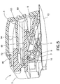
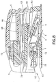
- FIGS. 6 and 10 illustrate an infusion set assembly 1 and motion to insert a needle 6 via a user motion in a first direction (indicated by arrow 94 in FIGS. 6 and 7 ) relative to a skin surface that is different from a second direction (indicated by the angle ⁇ in FIGS. 6 and 7 ) of the inserted needle in accordance with an exemplary embodiment of the present invention.
- FIGS. 4 - 6 illustrate an infusion set assembly 1 in a free state before use.
- FIG. 10 illustrates the infusion set assembly 1 during insertion into the skin surface at an angle relative thereto via a user motion occurring at an angle to the skin surface that is different from the needle insertion angle, in accordance with an exemplary embodiment of the present invention.
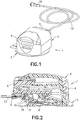
- An infusion set assembly 1 includes an inserter 2 and an infusion set 3.
- the inserter 2 includes a fixed inserter member 4 and a movable inserter member 5 movably connected to the fixed inserter member 4.
- the movable inserter member 5 is movable from a first position shown in FIG. 5 to a second position shown in FIG. 10 .
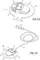
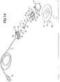
- the infusion set 3 includes a rigid needle 6, a hub 7, a movable slide member 8 and a fixed base member 9, as shown in FIG. 14 .
- An adhesive pad or patch 10 secures the base member 9 to the skin surface.
- the rigid needle 6 is fixedly connected to the hub 7, which is fixedly connected to the slide member 8.
- the slide member 8 moves relative to the fixed base member 9 from a first position in which the needle 6 is not exposed externally of the infusion set 3 to a second position in which the needle 6 is exposed externally of the infusion set 3.
- An opening 11 in the adhesive pad 10 allows the needle 6 to pass therethrough.
- a connector 12 connects tubing from an infusion pump (not shown) to the infusion set 3.
- the rigid needle 6 is preferably hollow to facilitate delivering medicament therethrough and is preferably made of 31 gauge stainless steel with a sharp beveled tip.
- An end port in a patient end of the needle 6 allows the medicament to be delivered into the infusion site.
- a side port can be used in addition to or instead of the end port.
- An opening in the non-patient end of the needle 6 receives medicament delivered from the insulin pump through tubing 13.
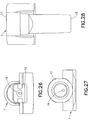
- the hub 7, as shown in FIGS. 26 - 30 fixedly receives the needle 6, which can be secured thereto in any suitable manner, such as with an adhesive.
- a bore 19 in the hub 7 receives the needle 6, which can be secured therein with an adhesive.
- the patient end 14 of the needle 6 extends beyond a first end 15 of the hub 7.
- a septum 16 is disposed in a second end 17 of the hub 7 to seal the hub and prevent access to the opening in the non-patient end 18 of the needle 6.
- the septum 16 is preferably made of isoprene, but any suitable material can be used.
- the hub 7 is preferably made of an injection-molded plastic, although any suitable material can be used.
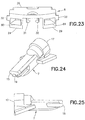
- the slide member 8, as shown in FIGS. 18 - 23 has a front end 23 and a rear end 24.
- An angled portion 25 of an upper surface 26 slopes upwardly from the front end 23 toward the rear end 24.
- the angled portion 25 has an angle of between approximately ten (10) and forty-five degrees (45), inclusive. More preferably, the angled portion has an angle of approximately twenty (20) degrees.
- An opening 27 is formed in the angled portion 25 of the upper surface 26.
- a cavity 28 is formed in a lower surface 29 of the slide member 8 to receive the hub 7. Flex arms 30 and 31 extend outwardly from the lower surface 29 proximal the cavity 28 to facilitate securing the hub 7 in the cavity 28.
- the hub 7 is secured at an angle substantially similar to the angle of the angled portion 25.
- Outer rails 32 and 33 extend outwardly from opposite sides of the slide member 8.
- the outer rails 32 and 33 are disposed at an angle substantially similar to that of the angled portion 25.
- Snap arms 34 and 35 are disposed inwardly of the outer rails 32 and 33.
- Hooks 36 and 37 extend upwardly from ends of the snap arms 34 and 35.
- Stop arms 38 and 39 are disposed between the outer rails 32 and 33 and the snap arms 34 and 35, respectively.
- Openings 80 and 81 in the rear end 24 receive connector arms 78 and 79 ( FIG. 14 ) to secure the connector 12 thereto.
- the slide member 8 is preferably made of an injection-molded plastic, such as PETG, but any suitable material can be used.
- the base member 9, as shown in FIGS. 41 - 46 has a front end 40 and a rear end 41.
- a lower surface 42 extends from the front end 40 toward the rear end 41.
- An opening 43 in the lower surface 42 allows the needle 6 to pass therethrough.
- the opening 43 has a substantially oval shape.
- An upper surface 44 extends rearwardly from the front end 40 and defines a cavity 45 between the upper surface 44 and the lower surface 42 for receiving the slide member 8.
- Outer channels 46 and 47 are formed in side walls 48 and 49 extending between the lower surface 42 and the upper surface 44.
- a lower tab 50 extends upwardly from the lower surface 42, as shown in FIG. 44 .
- Upper tabs 51 and 52 extend downwardly from the upper surface 44, as shown in FIGS. 42 and 44 .
- Inner channels 53 and 54 are disposed between upper tabs 51 and 52 and the channels 46 and 47.
- the base member 9 is preferably made of an injection-molded plastic, such as PETG, but any suitable material can be used.
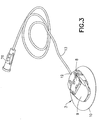
- a pressure sensitive adhesive pad 10 is connected to the lower surface 42 of the base member 9, as shown in FIGS. 1 , 3 and 14 .
- An adhesive backing 55 is connected to the adhesive pad 10 to cover the adhesive pad prior to use.
- the adhesive backing 55 has a tab element 56 to facilitate separating the cover from the adhesive pad 10 to expose the adhesive pad when the adhesive pad is to be secured to an infusion site.
- the pressure sensitive adhesive pad 10 can comprise any suitable material, such as an adhesive fabric.
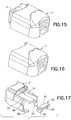
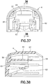
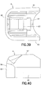
- the fixed inserter member 4 has an upper surface 57 with a wall 58 extending downwardly therefrom, as shown in FIGS. 35 - 40 .
- the upper surface 57 and the wall 58 define a cavity 59.
- the wall 58 has a front wall 60 and opposing side walls 61 and 62 with a rear portion thereof being open to provide access to the cavity 59.
- a shelf 63 disposed in the cavity 59 extends laterally between the side walls 61 and 62.
- a flexible beam 64 extends rearwardly from the front wall 60 in the cavity 59.
- the fixed inserter member 4 is preferably made of an injection-molded plastic, such as acrylonitrile butadiene styrene (ABS), but any suitable material can be used.
- ABS acrylonitrile butadiene styrene
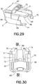
- the movable inserter member 5 has a rear wall 65 and opposing side walls 66 and 67 extending forwardly therefrom, as shown in FIGS. 29 - 34 .
- a latching arm 68 extends forwardly from the rear wall 65 and has a tab 69 extending downwardly from a free end thereof. Slots 70 and 71 extend parallel to opposite sides of the latching arm 68.
- a flexible member 72 is preferably connected to the movable inserter member 5 by a living hinge 73, although any suitable means for connecting the flexible member can be used that allows deflection of the flexible member.
- Locking feet 74 and 75 extend forwardly from side walls 66 and 67.
- the movable inserter member 5 is preferably made of an injection-molded plastic, such as PETG, but any suitable material can be used.
- the connector 12 has flexible plastic tubing 13 connected thereto for delivering medicament from the insulin pump (not shown) to the infusion set 3, as shown in FIG. 14 .
- a pump connector 76 is disposed at one of the tubing 13 for connecting to the insulin pump.
- the connector 12 is disposed at the other end of the tubing 13 for connecting to the slide member 8 of the infusion set 3.
- the tubing 13 connects through a rear surface 89 of the connector 12.
- a needle 77 extends forwardly from the connector 12 to pierce the septum 16 disposed in the hub 7 when the connector 12 is connected to the slide member 8. By piercing the hub septum 16, the hub needle 6 is fluidly connected to the insulin pump.
- Snap arms 78 and 79 are received by the slide member 8 to secure the connector 12 thereto. Moving the snap arms 78 and 79 inwardly allows the connector 12 to be disconnected from the infusion set 3 as necessary.
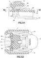
- a connector tab 82 as shown in FIGS. 17 and 48 - 51 , has a base 83 and legs 84 and 85 extending downwardly from the base 83.
- the legs 84 and 85 of the connector tab 82 are received by the slots 70 and 71 of the movable inserter member 5 such that the base 83 is disposed above the latching arm 68.
- the connector tab 82 can be integrally formed with the movable inserter member 5 as a single piece.
- the exemplary embodiments comprise an adhesive secured infusion set 3 and a disposable inserter 2 for performing an intradermal needle insertion precisely targeting the upper 3 mm of skin surface.
- the infusion set 3 can be adhesively attached to a skin surface, and the inserter 2 can be used to angularly insert the needle 6 into a desired insertion position.
- the insertion position of the needle 6 is maintained by securing the slide member 8 to the base member 9 to hold the inserted needle 6 in position and prevent the slide member 8 and inserted needle 6 from retraction once in the inserted position.
- the infusion set assembly 1 can include a disposable inserter 2, as shown in FIGS. 1 and 2 .
- the inserter 2 can also be reusable if desired.
- the infusion set assembly 1 is packaged such that the infusion set 3 is retained by the inserter 2.
- the infusion set 3 can be packaged without the inserter 2.
- the needle 6 is initially slightly recessed in the infusion set 6 to substantially prevent an accidental needle stick, but is visible from a bottom of the infusion set 2, as shown in FIG. 4 , so a user can visibly determine priming of the infusion set 3 prior to adhering the infusion set 3 to an infusion site.
- the exemplary embodiments are configured to be efficient and user friendly.
- the user first peels off the adhesive backing 55, revealing the adhesive pad 10 on the lower surface 42 of the base member 9 of the infusion set 3.
- the infusion set assembly 1 can then be adhered to the infusion site with a downward pressure or application force by the user.
- the sliding action of the sliding base member 5 angularly inserts the needle 6, as described in greater detail below, into the upper 3 mm of skin surface, the intradermal space, to facilitate better drug absorption.
- the inserter 2 can be removed and properly disposed of. The user can disconnect and reconnect the connector 12 as desired.
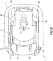
- the infusion set slide member 8 and the movable inserter member 5 are locked in their first positions, as shown in FIGS. 4 - 6 .
- the needle 6 is recessed within and visible through the openings 11 and 43 in the adhesive pad 10 and the base member 9, respectively, as shown in FIG. 4 , thereby preventing accidental needle sticks and allowing for visible priming of the infusion set 3.
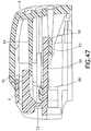
- the tab 69 of the latching arm 68 of the movable inserter member 5 engages the shelf 63 of the fixed inserter member 4, as shown in FIGS. 5 , 47 and 48 , thereby preventing the movable inserter member from being separated from the fixed inserter member 4.
- the flexible beam 64 of the fixed inserter member 4 engages ribs 86 extending downwardly from the flexible member 72 of the movable inserter member 5, as shown in FIG. 47 , thereby preventing accidental activation of the infusion set 3. Accordingly, the movable inserter member 5 is prevented from being withdrawn from the fixed inserter member 4 in addition to being prevented from being moved into the fixed inserter member.
- the infusion set 3 is prevented from being removed from the inserter 2 prior to activation, as shown in FIG. 4 .
- the locking feet 74 and 75 of the movable inserter member 4 engage longitudinally extending base members 87 and 88 ( FIG. 42 ), thereby preventing removal of the inserter 2 from infusion set 3 prior to fully inserting the needle 6.
- Inwardly extending retaining ribs 90 and 91 engage the rear surface 89 of the connector 12 to prevent withdrawal of the infusion set 3 from the inserter 2 prior to activation. Accordingly, the infusion set 3 is retained by the inserter 2 prior to activation and until the needle 6 is fully inserted.
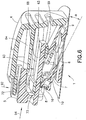
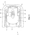
- the infusion set 3 is activated by moving the flexible member 72 and squeezing the inserter 2 together, as shown in FIGS. 6 and 7 .
- the flexible member 72 engages and moves the flexible beam 64 of the fixed inserter member 4 downwardly (indicated by arrow 93 in FIG. 6 ), thereby allowing the flexible member 72 of the movable inserter member 5 to slide into the fixed inserter member 4 (indicated by arrow 94 in FIG. 7 ).
- the movable inserter member 5 slides into the fixed inserter member 5, as shown in FIG. 8 , the movable inserter member 5 pushes the rear surface of the connector 12. As shown in FIG. 9 , the inwardly extending retaining ribs 90 and 91 of the movable inserter member 5 engage and push the connector 12 in a forward direction.
- the connector 12 is connected to the infusion set slide member 8, such that the slide member 8 moves forwardly with forward movement of the connector 12.
- the slide member 9 moves into the infusion set base member 9, thereby inserting the needle 6 into the dermis layer.
- the movable inserter member 5 is partially inserted in the fixed inserter member 4 such that the needle is partially inserted.
- the locking feet 74 and 75 of the movable inserter member 5 still engage the longitudinally extending base member 87 and 88 of the fixed inserter member 9, as shown in FIG. 9 , such that the inserter 2 cannot yet be removed from the infusion set 3. Accordingly, the inserter 2 is prevented from being removed from the infusion set 3 until the needle 6 is fully inserted, thereby preventing the user from inadvertently inserting the needle 6 only partially.
- the legs 84 and 85 of the connector tab 82 engage a rear end 24 of the slide member 8, thereby further facilitate forward movement of the slide member 8 with forward movement of the movable inserter member 5 to which the connector tab 82 is connected.
- the forward movement of the movable inserter member 5 causes the connector 12 to move forwardly, which causes the movement of the infusion set slide member 8 toward the fully inserted second position.
- the outer rails 32 and 33 ( FIGS. 18 - 23 ) are guided by the outer channels 46 and 47 ( FIGS. 41, 42 and 44 ) in the infusion set fixed member 9.
- the outer channels 46 and 47 guide the slide member 8 forwardly at an angle ⁇ ( FIGS. 6 and 44 ) relative to the skin surface.
- the angle ⁇ is between approximately ten (10) and forty-five (45) degrees, inclusive. More preferably, the angle ⁇ is approximately twenty (20) degrees.
- the needle 6 is preferably aligned with the angular insertion direction of the slide member 8 such that the needle is inserted in the substantially axial direction of the hub 7.
- the needle 6 can be offset from the insertion angle ⁇ such that the insertion direction of the needle 6 includes both axial and radial components with respect to the hub 7.
- the orientation angle of the needle 6 is offset from the insertion slide angle of the slide member 8 and the hub 7.
- the locking feet 74 and 75 of the movable inserter member 4 have moved past the longitudinally extending base members 87 and 88. Additionally, rear portions 95 and 96 of the locking feet 74 and 75 can engage rear portions 97 and 98 of the longitudinally extending base members 87 and 88 to further facilitate preventing removal of the inserter 2 until the needle 6 is fully inserted.
- the rear portions 95 and 96 of the locking feet 74 and 75 are clear of rear portions 97 and 98 of the longitudinally extending base members 87 and 88 when the locking feet 74 and 75 are clear of the longitudinally extending base members 87 and 88.
- inserter 2 can now be removed from the infusion set 3 by lifting the inserter upwardly with respect to the infusion set 3 and be properly disposed of.
- the connector 12 can be removed and connected to the slide member 8 as desired.
- the slide member 8 is permanently locked to the base member 9, as described above, thereby maintaining the needle 6 in its intradermally injected position until the set 3 is removed by the user.
- the angular insertion of the needle 6 provides a solid anchor that maintains the infusion site. Typically, it is very difficult to maintain the position of short (i.e., 1 - 3 mm) needles within the skin. However, by angularly inserting the needle 6, the skin itself provides a vertical retention force. Accordingly, the inserted needle 6 is secured both vertically and horizontally. Furthermore, the angled insertion allows for more flexibility of needle or cannula choice for infusion by reducing the vertical height of the cannula opening. Also, because the needle 6 is inserted at an angle, a longer needle and/or needle opening can be used than those provided for a non-angled insertion to target the same intradermal depth.
- a precise mechanical foundation is provided which ensures that the needle angle, skin tensioning, stretching and/or flattening, and insertion depth are consistent. Further, in doing so, tenting is also reduced or eliminated. Still further, by isolating the needle site from the pump connection, vibrations and movements are reduced. In addition, a low-profile is provided which further isolates the needle 6 from any external forces.
- the exemplary embodiments of the present invention offer the potential for better absorption of insulin when compared to subcutaneous delivery systems. In doing so, it may be possible for the typical user to both consume less insulin and maintain a better medicament regime. It will be appreciated that multiple needles or microneedles can be used, if desired, in place of a single needle or microneedle.
- Proper alignment is accomplished by providing a solid, fixed foundation for the user to slide the movable inserter member 5 to angularly insert the needle 6.
- a solid, fixed foundation is provided by the adhesive layer 10.
- the skin adhesive layer secures the infusion set 3 at a desired orientation, such that the needle hub 7 and needle 6 are at a desired orientation of use, and the user is substantially prevented from holding the infusion set 3 at various angles to the insertion site. Accordingly, precise, repeatable insertions are accomplished.
- the angle of the needle hub can be changed in this or other exemplary embodiments of the present invention to affect the insertion angle and final placement of the needle.
- the needle 6 is aligned with the direction of travel of the hub 7.
- the needle 6 can be offset from the direction of travel of the hub 7.
- the infusion set 3 can be activated without the inserter 2.
- the insertion is fully integrated into the infusion set 3 such that the user does not have to carry the inserter or load the infusion set into the inserter.
- the integrated system allows the user more freedom from carrying the inserter 2.
- Such a system and method is economical, simple, and compact, and provides a system of insertion that is integrated with the device. Therefore, a user can correctly insert the device without inserter 2.
- the principles of the present invention are also applicable to other types of infusion sets, for example, subcutaneous infusion sets in which the patient cannula consists of a soft plastic catheter that is inserted with the aid of a rigid metal introducer needle.
Landscapes
- Health & Medical Sciences (AREA)
- Heart & Thoracic Surgery (AREA)
- Vascular Medicine (AREA)
- Engineering & Computer Science (AREA)
- Anesthesiology (AREA)
- Biomedical Technology (AREA)
- Hematology (AREA)
- Life Sciences & Earth Sciences (AREA)
- Animal Behavior & Ethology (AREA)
- General Health & Medical Sciences (AREA)
- Public Health (AREA)
- Veterinary Medicine (AREA)
- Dermatology (AREA)
- Infusion, Injection, And Reservoir Apparatuses (AREA)
Applications Claiming Priority (2)
| Application Number | Priority Date | Filing Date | Title |
|---|---|---|---|
| US13/629,479 US9782538B2 (en) | 2012-09-27 | 2012-09-27 | Angled inserter for drug infusion |
| EP13185981.1A EP2712641B1 (en) | 2012-09-27 | 2013-09-25 | Angled inserter for drug infusion |
Related Parent Applications (1)
| Application Number | Title | Priority Date | Filing Date |
|---|---|---|---|
| EP13185981.1A Division EP2712641B1 (en) | 2012-09-27 | 2013-09-25 | Angled inserter for drug infusion |
Publications (2)
| Publication Number | Publication Date |
|---|---|
| EP3263157A1 EP3263157A1 (en) | 2018-01-03 |
| EP3263157B1 true EP3263157B1 (en) | 2020-11-11 |
Family
ID=49328320
Family Applications (2)
| Application Number | Title | Priority Date | Filing Date |
|---|---|---|---|
| EP13185981.1A Active EP2712641B1 (en) | 2012-09-27 | 2013-09-25 | Angled inserter for drug infusion |
| EP17184762.7A Active EP3263157B1 (en) | 2012-09-27 | 2013-09-25 | Angled inserter for drug infusion |
Family Applications Before (1)
| Application Number | Title | Priority Date | Filing Date |
|---|---|---|---|
| EP13185981.1A Active EP2712641B1 (en) | 2012-09-27 | 2013-09-25 | Angled inserter for drug infusion |
Country Status (6)
| Country | Link |
|---|---|
| US (2) | US9782538B2 (ru) |
| EP (2) | EP2712641B1 (ru) |
| JP (2) | JP6334120B2 (ru) |
| CN (1) | CN203694220U (ru) |
| CA (2) | CA3130724C (ru) |
| ES (2) | ES2847848T3 (ru) |
Families Citing this family (30)
| Publication number | Priority date | Publication date | Assignee | Title |
|---|---|---|---|---|
| PT1762259E (pt) | 2005-09-12 | 2010-12-10 | Unomedical As | Insersor para um conjunto de infusão com uma primeira e uma segunda unidades de mola |
| MX2012011085A (es) | 2010-03-30 | 2012-10-10 | Unomedical As | Dispositivo medico. |
| WO2012123274A1 (en) | 2011-03-14 | 2012-09-20 | Unomedical A/S | Inserter system with transport protection |
| EP2763723B1 (en) | 2011-10-05 | 2016-04-13 | Unomedical A/S | Inserter for simultaneous insertion of multiple transcutaneous parts |
| EP2583715A1 (en) | 2011-10-19 | 2013-04-24 | Unomedical A/S | Infusion tube system and method for manufacture |
| ES2842529T3 (es) | 2011-12-07 | 2021-07-14 | Becton Dickinson Co | Dispositivo de infusión con conector para fluidos removible |
| ES2694176T3 (es) | 2011-12-07 | 2018-12-18 | Becton, Dickinson And Company | Conjuntos de protección de aguja y dispositivos de infusión para su uso con los mismos |
| USD754843S1 (en) * | 2012-12-07 | 2016-04-26 | Becton, Dickinson And Company | Infusion set assembly |
| USD747456S1 (en) * | 2012-12-07 | 2016-01-12 | Becton, Dickinson And Company | Infusion set assembly |
| USD747457S1 (en) * | 2012-12-07 | 2016-01-12 | Becton, Dickinson And Company | Infusion set needle guard |
| USD756504S1 (en) * | 2012-12-07 | 2016-05-17 | Becton, Dickinson And Company | Infusion set base |
| USD754842S1 (en) * | 2012-12-07 | 2016-04-26 | Becton, Dickinson And Company | Infusion set needle guard |
| USD747459S1 (en) * | 2012-12-07 | 2016-01-12 | Becton, Dickinson And Company | Infusion set assembly |
| USD747458S1 (en) * | 2012-12-07 | 2016-01-12 | Becton, Dickinson And Company | Infusion set insertion needle assembly |
| US10080839B2 (en) | 2013-03-14 | 2018-09-25 | Becton, Dickinson And Company | Angled inserter for drug infusion |
| ES2981280T3 (es) | 2014-06-03 | 2024-10-08 | Amgen Inc | Sistema de administración de fármacos controlable y método de uso |
| US11357916B2 (en) | 2014-12-19 | 2022-06-14 | Amgen Inc. | Drug delivery device with live button or user interface field |
| US10799630B2 (en) | 2014-12-19 | 2020-10-13 | Amgen Inc. | Drug delivery device with proximity sensor |
| CN108778370B (zh) | 2016-01-19 | 2021-10-08 | 优诺医疗有限公司 | 套管和输液装置 |
| EP3760274B1 (en) * | 2016-05-26 | 2023-05-31 | Medtronic Minimed, Inc. | Systems for set connector assembly with lock |
| EP3260151A1 (en) * | 2016-06-23 | 2017-12-27 | TecPharma Licensing AG | A needle insertion and retraction mechanism for a medication delivery device |
| USD813380S1 (en) | 2016-08-05 | 2018-03-20 | Amgen Inc. | On-body injector |
| EP3600493A4 (en) | 2017-03-31 | 2020-08-19 | Capillary Biomedical, Inc. | HELICOIDAL INSERTION INFUSION DEVICE |
| JP2019205792A (ja) * | 2018-05-30 | 2019-12-05 | 大成化工株式会社 | 皮内注射用補助具 |
| US11213665B2 (en) * | 2018-06-15 | 2022-01-04 | Esthetic Education LLC | Angled microneedle cartridge |
| CA3208266C (en) | 2019-02-22 | 2024-04-16 | Deka Products Limited Partnership | Infusion set and inserter assembly systems and methods |
| SG11202111673SA (en) | 2019-05-20 | 2021-11-29 | Unomedical As | Rotatable infusion device and methods thereof |
| WO2022261543A2 (en) * | 2021-06-11 | 2022-12-15 | Bristol-Myers Squibb Company | Drug cartridge, drug delivery device, and methods for preparing thereof |
| USD1013864S1 (en) | 2021-08-26 | 2024-02-06 | Deka Products Limited Partnership | Fluid administration apparatus assembly |
| USD1043976S1 (en) | 2022-08-26 | 2024-09-24 | Deka Products Limited Partnership | Fluid transfer connector |
Family Cites Families (28)
| Publication number | Priority date | Publication date | Assignee | Title |
|---|---|---|---|---|
| US5688254A (en) | 1983-01-24 | 1997-11-18 | Icu Medical, Inc. | Medical connector |
| US5545143A (en) | 1993-01-21 | 1996-08-13 | T. S. I. Medical | Device for subcutaneous medication delivery |
| DK25793A (da) | 1993-03-09 | 1994-09-10 | Pharma Plast Int As | Infusionssæt til intermitterende eller kontinuerlig indgivelse af et terapeutisk middel |
| US5545152A (en) | 1994-10-28 | 1996-08-13 | Minimed Inc. | Quick-connect coupling for a medication infusion system |
| US7329239B2 (en) | 1997-02-05 | 2008-02-12 | Medtronic Minimed, Inc. | Insertion device for an insertion set and method of using the same |
| US6607509B2 (en) | 1997-12-31 | 2003-08-19 | Medtronic Minimed, Inc. | Insertion device for an insertion set and method of using the same |
| CA2484271C (en) | 1997-12-31 | 2007-04-24 | Medtronic Minimed, Inc. | Insertion device for an insertion set and method of using the same |
| US6086575A (en) | 1998-03-20 | 2000-07-11 | Maersk Medical A/S | Subcutaneous infusion device |
| US6123690A (en) | 1998-03-20 | 2000-09-26 | Maersk Medical A/S | Subcutaneous infusion device |
| US5980506A (en) | 1998-03-20 | 1999-11-09 | Mathiasen; Orla | Subcutaneous infusion device |
| DE10004496A1 (de) | 2000-02-02 | 2000-08-03 | Meonic Sys Eng Gmbh | Vorrichtung und Verfahren zur Injektion eines Medikamentes |
| US7052483B2 (en) * | 2000-12-19 | 2006-05-30 | Animas Corporation | Transcutaneous inserter for low-profile infusion sets |
| US6830562B2 (en) * | 2001-09-27 | 2004-12-14 | Unomedical A/S | Injector device for placing a subcutaneous infusion set |
| US7429258B2 (en) | 2001-10-26 | 2008-09-30 | Massachusetts Institute Of Technology | Microneedle transport device |
| US20090012472A1 (en) | 2004-09-22 | 2009-01-08 | Novo Nordisk A/S | Medical Device with Cannula Inserter |
| US7303543B1 (en) | 2004-12-03 | 2007-12-04 | Medtronic Minimed, Inc. | Medication infusion set |
| US20060184104A1 (en) | 2005-02-15 | 2006-08-17 | Medtronic Minimed, Inc. | Needle guard |
| WO2006108809A1 (en) | 2005-04-13 | 2006-10-19 | Novo Nordisk A/S | Medical skin mountable device and system |
| DK1968677T3 (da) | 2005-09-15 | 2019-07-15 | Hoffmann La Roche | Indføringshoved med kanylebeskyttelse i håndtaget |
| US20070282269A1 (en) | 2006-05-31 | 2007-12-06 | Seattle Medical Technologies | Cannula delivery apparatus and method for a disposable infusion device |
| EP2032188A1 (en) | 2006-06-06 | 2009-03-11 | Novo Nordisk A/S | Assembly comprising skin-mountable device and packaging therefore |
| CA2660392A1 (en) | 2006-08-24 | 2008-02-28 | F. Hoffmann-La Roche Ag | Insertion device for insertion heads, in particular for infusion sets |
| US20080167620A1 (en) | 2007-01-09 | 2008-07-10 | Seattle Medical Technologies | Disposable infusion device facilitating tissue fold formation for cannula deployment and method |
| GB2445437B (en) | 2007-07-06 | 2008-11-26 | Applied Medical Technology Ltd | Cannula insertion device |
| WO2009016638A1 (en) | 2007-08-01 | 2009-02-05 | Medingo Ltd. | Device for facilitating infusion of therapeutic fluids and sensing of bodily analytes |
| EP2231231B1 (en) * | 2007-12-10 | 2019-03-06 | Medtronic Minimed, Inc. | Insertion system and insertion device |
| EP2327433B1 (en) | 2009-11-26 | 2012-04-18 | F. Hoffmann-La Roche AG | Externally triggerable cannula assembly |
| US9950109B2 (en) * | 2010-11-30 | 2018-04-24 | Becton, Dickinson And Company | Slide-activated angled inserter and cantilevered ballistic insertion for intradermal drug infusion |
-
2012
- 2012-09-27 US US13/629,479 patent/US9782538B2/en active Active
-
2013
- 2013-09-23 CA CA3130724A patent/CA3130724C/en active Active
- 2013-09-23 CA CA2827953A patent/CA2827953C/en active Active
- 2013-09-25 ES ES17184762T patent/ES2847848T3/es active Active
- 2013-09-25 EP EP13185981.1A patent/EP2712641B1/en active Active
- 2013-09-25 ES ES13185981.1T patent/ES2646589T3/es active Active
- 2013-09-25 EP EP17184762.7A patent/EP3263157B1/en active Active
- 2013-09-27 JP JP2013201686A patent/JP6334120B2/ja active Active
- 2013-09-27 CN CN201320896801.1U patent/CN203694220U/zh not_active Expired - Lifetime
-
2017
- 2017-09-08 US US15/699,235 patent/US10729844B2/en active Active
-
2018
- 2018-04-26 JP JP2018085449A patent/JP2018114339A/ja active Pending
Non-Patent Citations (1)
| Title |
|---|
| None * |
Also Published As
| Publication number | Publication date |
|---|---|
| CA3130724C (en) | 2023-08-22 |
| EP2712641B1 (en) | 2017-08-09 |
| CA3130724A1 (en) | 2014-03-27 |
| CA2827953A1 (en) | 2014-03-27 |
| US10729844B2 (en) | 2020-08-04 |
| EP2712641A1 (en) | 2014-04-02 |
| US20140088549A1 (en) | 2014-03-27 |
| US20170368257A1 (en) | 2017-12-28 |
| ES2646589T3 (es) | 2017-12-14 |
| CN203694220U (zh) | 2014-07-09 |
| CA2827953C (en) | 2021-11-02 |
| JP2018114339A (ja) | 2018-07-26 |
| JP6334120B2 (ja) | 2018-05-30 |
| JP2014069084A (ja) | 2014-04-21 |
| ES2847848T3 (es) | 2021-08-04 |
| US9782538B2 (en) | 2017-10-10 |
| EP3263157A1 (en) | 2018-01-03 |
Similar Documents
| Publication | Publication Date | Title |
|---|---|---|
| US10729844B2 (en) | Angled inserter for drug infusion | |
| US10729845B2 (en) | Angled inserter for drug infusion | |
| EP2968891B1 (en) | Automatic angled infusion set assembly | |
| US10413660B2 (en) | Perpendicular infusion set and disposable inserter | |
| EP3167922A1 (en) | Slide-activated angled inserter and cantilevered ballistic insertion for intradermal drug infusion |
Legal Events
| Date | Code | Title | Description |
|---|---|---|---|
| PUAI | Public reference made under article 153(3) epc to a published international application that has entered the european phase |
Free format text: ORIGINAL CODE: 0009012 |
|
| STAA | Information on the status of an ep patent application or granted ep patent |
Free format text: STATUS: THE APPLICATION HAS BEEN PUBLISHED |
|
| AC | Divisional application: reference to earlier application |
Ref document number: 2712641 Country of ref document: EP Kind code of ref document: P |
|
| AK | Designated contracting states |
Kind code of ref document: A1 Designated state(s): AL AT BE BG CH CY CZ DE DK EE ES FI FR GB GR HR HU IE IS IT LI LT LU LV MC MK MT NL NO PL PT RO RS SE SI SK SM TR |
|
| STAA | Information on the status of an ep patent application or granted ep patent |
Free format text: STATUS: REQUEST FOR EXAMINATION WAS MADE |
|
| 17P | Request for examination filed |
Effective date: 20180604 |
|
| RBV | Designated contracting states (corrected) |
Designated state(s): AL AT BE BG CH CY CZ DE DK EE ES FI FR GB GR HR HU IE IS IT LI LT LU LV MC MK MT NL NO PL PT RO RS SE SI SK SM TR |
|
| STAA | Information on the status of an ep patent application or granted ep patent |
Free format text: STATUS: EXAMINATION IS IN PROGRESS |
|
| 17Q | First examination report despatched |
Effective date: 20190607 |
|
| GRAP | Despatch of communication of intention to grant a patent |
Free format text: ORIGINAL CODE: EPIDOSNIGR1 |
|
| STAA | Information on the status of an ep patent application or granted ep patent |
Free format text: STATUS: GRANT OF PATENT IS INTENDED |
|
| INTG | Intention to grant announced |
Effective date: 20200331 |
|
| RAP1 | Party data changed (applicant data changed or rights of an application transferred) |
Owner name: BECTON, DICKINSON AND COMPANY |
|
| RIN1 | Information on inventor provided before grant (corrected) |
Inventor name: COLE, RUSSEL Inventor name: KLOTZ, ARTHUR |
|
| GRAJ | Information related to disapproval of communication of intention to grant by the applicant or resumption of examination proceedings by the epo deleted |
Free format text: ORIGINAL CODE: EPIDOSDIGR1 |
|
| STAA | Information on the status of an ep patent application or granted ep patent |
Free format text: STATUS: EXAMINATION IS IN PROGRESS |
|
| INTC | Intention to grant announced (deleted) | ||
| GRAS | Grant fee paid |
Free format text: ORIGINAL CODE: EPIDOSNIGR3 |
|
| STAA | Information on the status of an ep patent application or granted ep patent |
Free format text: STATUS: GRANT OF PATENT IS INTENDED |
|
| GRAP | Despatch of communication of intention to grant a patent |
Free format text: ORIGINAL CODE: EPIDOSNIGR1 |
|
| GRAA | (expected) grant |
Free format text: ORIGINAL CODE: 0009210 |
|
| STAA | Information on the status of an ep patent application or granted ep patent |
Free format text: STATUS: THE PATENT HAS BEEN GRANTED |
|
| INTG | Intention to grant announced |
Effective date: 20200922 |
|
| AC | Divisional application: reference to earlier application |
Ref document number: 2712641 Country of ref document: EP Kind code of ref document: P |
|
| AK | Designated contracting states |
Kind code of ref document: B1 Designated state(s): AL AT BE BG CH CY CZ DE DK EE ES FI FR GB GR HR HU IE IS IT LI LT LU LV MC MK MT NL NO PL PT RO RS SE SI SK SM TR |
|
| REG | Reference to a national code |
Ref country code: GB Ref legal event code: FG4D |
|
| REG | Reference to a national code |
Ref country code: CH Ref legal event code: EP |
|
| REG | Reference to a national code |
Ref country code: AT Ref legal event code: REF Ref document number: 1332854 Country of ref document: AT Kind code of ref document: T Effective date: 20201115 |
|
| REG | Reference to a national code |
Ref country code: DE Ref legal event code: R096 Ref document number: 602013074063 Country of ref document: DE |
|
| REG | Reference to a national code |
Ref country code: IE Ref legal event code: FG4D |
|
| REG | Reference to a national code |
Ref country code: NL Ref legal event code: MP Effective date: 20201111 |
|
| REG | Reference to a national code |
Ref country code: AT Ref legal event code: MK05 Ref document number: 1332854 Country of ref document: AT Kind code of ref document: T Effective date: 20201111 |
|
| PG25 | Lapsed in a contracting state [announced via postgrant information from national office to epo] |
Ref country code: GR Free format text: LAPSE BECAUSE OF FAILURE TO SUBMIT A TRANSLATION OF THE DESCRIPTION OR TO PAY THE FEE WITHIN THE PRESCRIBED TIME-LIMIT Effective date: 20210212 Ref country code: FI Free format text: LAPSE BECAUSE OF FAILURE TO SUBMIT A TRANSLATION OF THE DESCRIPTION OR TO PAY THE FEE WITHIN THE PRESCRIBED TIME-LIMIT Effective date: 20201111 Ref country code: RS Free format text: LAPSE BECAUSE OF FAILURE TO SUBMIT A TRANSLATION OF THE DESCRIPTION OR TO PAY THE FEE WITHIN THE PRESCRIBED TIME-LIMIT Effective date: 20201111 Ref country code: PT Free format text: LAPSE BECAUSE OF FAILURE TO SUBMIT A TRANSLATION OF THE DESCRIPTION OR TO PAY THE FEE WITHIN THE PRESCRIBED TIME-LIMIT Effective date: 20210311 Ref country code: NO Free format text: LAPSE BECAUSE OF FAILURE TO SUBMIT A TRANSLATION OF THE DESCRIPTION OR TO PAY THE FEE WITHIN THE PRESCRIBED TIME-LIMIT Effective date: 20210211 |
|
| PG25 | Lapsed in a contracting state [announced via postgrant information from national office to epo] |
Ref country code: SE Free format text: LAPSE BECAUSE OF FAILURE TO SUBMIT A TRANSLATION OF THE DESCRIPTION OR TO PAY THE FEE WITHIN THE PRESCRIBED TIME-LIMIT Effective date: 20201111 Ref country code: BG Free format text: LAPSE BECAUSE OF FAILURE TO SUBMIT A TRANSLATION OF THE DESCRIPTION OR TO PAY THE FEE WITHIN THE PRESCRIBED TIME-LIMIT Effective date: 20210211 Ref country code: IS Free format text: LAPSE BECAUSE OF FAILURE TO SUBMIT A TRANSLATION OF THE DESCRIPTION OR TO PAY THE FEE WITHIN THE PRESCRIBED TIME-LIMIT Effective date: 20210311 Ref country code: PL Free format text: LAPSE BECAUSE OF FAILURE TO SUBMIT A TRANSLATION OF THE DESCRIPTION OR TO PAY THE FEE WITHIN THE PRESCRIBED TIME-LIMIT Effective date: 20201111 Ref country code: LV Free format text: LAPSE BECAUSE OF FAILURE TO SUBMIT A TRANSLATION OF THE DESCRIPTION OR TO PAY THE FEE WITHIN THE PRESCRIBED TIME-LIMIT Effective date: 20201111 Ref country code: AT Free format text: LAPSE BECAUSE OF FAILURE TO SUBMIT A TRANSLATION OF THE DESCRIPTION OR TO PAY THE FEE WITHIN THE PRESCRIBED TIME-LIMIT Effective date: 20201111 |
|
| REG | Reference to a national code |
Ref country code: LT Ref legal event code: MG9D |
|
| PG25 | Lapsed in a contracting state [announced via postgrant information from national office to epo] |
Ref country code: HR Free format text: LAPSE BECAUSE OF FAILURE TO SUBMIT A TRANSLATION OF THE DESCRIPTION OR TO PAY THE FEE WITHIN THE PRESCRIBED TIME-LIMIT Effective date: 20201111 |
|
| PG25 | Lapsed in a contracting state [announced via postgrant information from national office to epo] |
Ref country code: SK Free format text: LAPSE BECAUSE OF FAILURE TO SUBMIT A TRANSLATION OF THE DESCRIPTION OR TO PAY THE FEE WITHIN THE PRESCRIBED TIME-LIMIT Effective date: 20201111 Ref country code: RO Free format text: LAPSE BECAUSE OF FAILURE TO SUBMIT A TRANSLATION OF THE DESCRIPTION OR TO PAY THE FEE WITHIN THE PRESCRIBED TIME-LIMIT Effective date: 20201111 Ref country code: CZ Free format text: LAPSE BECAUSE OF FAILURE TO SUBMIT A TRANSLATION OF THE DESCRIPTION OR TO PAY THE FEE WITHIN THE PRESCRIBED TIME-LIMIT Effective date: 20201111 Ref country code: EE Free format text: LAPSE BECAUSE OF FAILURE TO SUBMIT A TRANSLATION OF THE DESCRIPTION OR TO PAY THE FEE WITHIN THE PRESCRIBED TIME-LIMIT Effective date: 20201111 Ref country code: SM Free format text: LAPSE BECAUSE OF FAILURE TO SUBMIT A TRANSLATION OF THE DESCRIPTION OR TO PAY THE FEE WITHIN THE PRESCRIBED TIME-LIMIT Effective date: 20201111 Ref country code: LT Free format text: LAPSE BECAUSE OF FAILURE TO SUBMIT A TRANSLATION OF THE DESCRIPTION OR TO PAY THE FEE WITHIN THE PRESCRIBED TIME-LIMIT Effective date: 20201111 |
|
| REG | Reference to a national code |
Ref country code: ES Ref legal event code: FG2A Ref document number: 2847848 Country of ref document: ES Kind code of ref document: T3 Effective date: 20210804 |
|
| REG | Reference to a national code |
Ref country code: DE Ref legal event code: R097 Ref document number: 602013074063 Country of ref document: DE |
|
| PG25 | Lapsed in a contracting state [announced via postgrant information from national office to epo] |
Ref country code: DK Free format text: LAPSE BECAUSE OF FAILURE TO SUBMIT A TRANSLATION OF THE DESCRIPTION OR TO PAY THE FEE WITHIN THE PRESCRIBED TIME-LIMIT Effective date: 20201111 |
|
| PLBE | No opposition filed within time limit |
Free format text: ORIGINAL CODE: 0009261 |
|
| STAA | Information on the status of an ep patent application or granted ep patent |
Free format text: STATUS: NO OPPOSITION FILED WITHIN TIME LIMIT |
|
| 26N | No opposition filed |
Effective date: 20210812 |
|
| PG25 | Lapsed in a contracting state [announced via postgrant information from national office to epo] |
Ref country code: AL Free format text: LAPSE BECAUSE OF FAILURE TO SUBMIT A TRANSLATION OF THE DESCRIPTION OR TO PAY THE FEE WITHIN THE PRESCRIBED TIME-LIMIT Effective date: 20201111 Ref country code: NL Free format text: LAPSE BECAUSE OF FAILURE TO SUBMIT A TRANSLATION OF THE DESCRIPTION OR TO PAY THE FEE WITHIN THE PRESCRIBED TIME-LIMIT Effective date: 20201111 |
|
| PG25 | Lapsed in a contracting state [announced via postgrant information from national office to epo] |
Ref country code: SI Free format text: LAPSE BECAUSE OF FAILURE TO SUBMIT A TRANSLATION OF THE DESCRIPTION OR TO PAY THE FEE WITHIN THE PRESCRIBED TIME-LIMIT Effective date: 20201111 |
|
| REG | Reference to a national code |
Ref country code: CH Ref legal event code: PL |
|
| REG | Reference to a national code |
Ref country code: BE Ref legal event code: MM Effective date: 20210930 |
|
| PG25 | Lapsed in a contracting state [announced via postgrant information from national office to epo] |
Ref country code: IS Free format text: LAPSE BECAUSE OF FAILURE TO SUBMIT A TRANSLATION OF THE DESCRIPTION OR TO PAY THE FEE WITHIN THE PRESCRIBED TIME-LIMIT Effective date: 20210311 Ref country code: MC Free format text: LAPSE BECAUSE OF FAILURE TO SUBMIT A TRANSLATION OF THE DESCRIPTION OR TO PAY THE FEE WITHIN THE PRESCRIBED TIME-LIMIT Effective date: 20201111 |
|
| PG25 | Lapsed in a contracting state [announced via postgrant information from national office to epo] |
Ref country code: LU Free format text: LAPSE BECAUSE OF NON-PAYMENT OF DUE FEES Effective date: 20210925 Ref country code: IE Free format text: LAPSE BECAUSE OF NON-PAYMENT OF DUE FEES Effective date: 20210925 Ref country code: BE Free format text: LAPSE BECAUSE OF NON-PAYMENT OF DUE FEES Effective date: 20210930 |
|
| PG25 | Lapsed in a contracting state [announced via postgrant information from national office to epo] |
Ref country code: LI Free format text: LAPSE BECAUSE OF NON-PAYMENT OF DUE FEES Effective date: 20210930 Ref country code: CH Free format text: LAPSE BECAUSE OF NON-PAYMENT OF DUE FEES Effective date: 20210930 |
|
| PG25 | Lapsed in a contracting state [announced via postgrant information from national office to epo] |
Ref country code: HU Free format text: LAPSE BECAUSE OF FAILURE TO SUBMIT A TRANSLATION OF THE DESCRIPTION OR TO PAY THE FEE WITHIN THE PRESCRIBED TIME-LIMIT; INVALID AB INITIO Effective date: 20130925 |
|
| PG25 | Lapsed in a contracting state [announced via postgrant information from national office to epo] |
Ref country code: CY Free format text: LAPSE BECAUSE OF FAILURE TO SUBMIT A TRANSLATION OF THE DESCRIPTION OR TO PAY THE FEE WITHIN THE PRESCRIBED TIME-LIMIT Effective date: 20201111 |
|
| PGFP | Annual fee paid to national office [announced via postgrant information from national office to epo] |
Ref country code: IT Payment date: 20230822 Year of fee payment: 11 Ref country code: GB Payment date: 20230823 Year of fee payment: 11 |
|
| PGFP | Annual fee paid to national office [announced via postgrant information from national office to epo] |
Ref country code: FR Payment date: 20230822 Year of fee payment: 11 Ref country code: DE Payment date: 20230822 Year of fee payment: 11 |
|
| PGFP | Annual fee paid to national office [announced via postgrant information from national office to epo] |
Ref country code: ES Payment date: 20231002 Year of fee payment: 11 |
|
| PG25 | Lapsed in a contracting state [announced via postgrant information from national office to epo] |
Ref country code: MK Free format text: LAPSE BECAUSE OF FAILURE TO SUBMIT A TRANSLATION OF THE DESCRIPTION OR TO PAY THE FEE WITHIN THE PRESCRIBED TIME-LIMIT Effective date: 20201111 |
|
| PG25 | Lapsed in a contracting state [announced via postgrant information from national office to epo] |
Ref country code: MT Free format text: LAPSE BECAUSE OF FAILURE TO SUBMIT A TRANSLATION OF THE DESCRIPTION OR TO PAY THE FEE WITHIN THE PRESCRIBED TIME-LIMIT Effective date: 20201111 |