EP3262913A1 - Agricultural spreader machine with operating centre - Google Patents
Agricultural spreader machine with operating centre Download PDFInfo
- Publication number
- EP3262913A1 EP3262913A1 EP17401067.8A EP17401067A EP3262913A1 EP 3262913 A1 EP3262913 A1 EP 3262913A1 EP 17401067 A EP17401067 A EP 17401067A EP 3262913 A1 EP3262913 A1 EP 3262913A1
- Authority
- EP
- European Patent Office
- Prior art keywords
- cover
- calibration
- working position
- distributor
- brought
- Prior art date
- Legal status (The legal status is an assumption and is not a legal conclusion. Google has not performed a legal analysis and makes no representation as to the accuracy of the status listed.)
- Granted
Links
Images
Classifications
-
- A—HUMAN NECESSITIES
- A01—AGRICULTURE; FORESTRY; ANIMAL HUSBANDRY; HUNTING; TRAPPING; FISHING
- A01C—PLANTING; SOWING; FERTILISING
- A01C7/00—Sowing
- A01C7/08—Broadcast seeders; Seeders depositing seeds in rows
- A01C7/12—Seeders with feeding wheels
- A01C7/123—Housings for feed rollers or wheels
-
- A—HUMAN NECESSITIES
- A01—AGRICULTURE; FORESTRY; ANIMAL HUSBANDRY; HUNTING; TRAPPING; FISHING
- A01C—PLANTING; SOWING; FERTILISING
- A01C7/00—Sowing
- A01C7/08—Broadcast seeders; Seeders depositing seeds in rows
- A01C7/10—Devices for adjusting the seed-box ; Regulation of machines for depositing quantities at intervals
- A01C7/107—Calibration of the seed rate
-
- A—HUMAN NECESSITIES
- A01—AGRICULTURE; FORESTRY; ANIMAL HUSBANDRY; HUNTING; TRAPPING; FISHING
- A01C—PLANTING; SOWING; FERTILISING
- A01C15/00—Fertiliser distributors
- A01C15/005—Undercarriages, tanks, hoppers, stirrers specially adapted for seeders or fertiliser distributors
- A01C15/006—Hoppers
Definitions
- the invention relates to an agricultural distribution machine according to the preamble of claim 1.
- Such a distributor is in the DE 10 2006 011 197 A1 described.
- the distributor described has a reservoir, which is supported on a frame.
- the frame in turn is supported by ground wheels or by means of a roller unit on the ground.
- the reservoir is associated with at least one metering.
- Below the metering a bottom flap is arranged, the setting is done by means of a Bodenklappeneinstellü.
- Below the dosing can be arranged to carry out a calibration Abwind anyer.
- a calibration flap is moved from a working position into a calibration and / or maintenance position by means of a calibration flap setting unit.
- the setting units of the distributor are combined in an operating center.
- the operating center is arranged on the left in the direction of the distribution machine.
- the invention is therefore based on the object to provide an arrangement which is suitable to ensure the coverage of the setting units and at the same time for the distribution process suitable settings of the setting units.
- the operating center can be covered by means of a cover and the cover can be moved to a calibration and / or maintenance position and a working position, the inner contour of the cover being shaped such that the cover is in its working position can be brought if all adjustment units combined in the operating center are in a suitable working position.
- the control center can not be covered with the cover when the bottom flaps are in the emptying position.
- the calibration is not in its working position, but in his necessary for the calibration calibration and / or maintenance position. In both exemplary cases, the movement of the cover into its working position is blocked by the inner contour of the cover colliding with the adjustment units or with the calibration container.
- the inner contour of the cover is designed to be variable so that the cover can be brought into its working position only when all the adjustment units combined in the operating center are in a specially set working position.
- the operator adjusts the distribution machine by means of the setting units of the operating center according to the impending distribution process.
- the adjustment units are in a specific work position for the upcoming distribution process.
- By adapting the inner contour of the cover to this special working position of the adjustment units of the operating center it is possible to move the cover into its position Working position only take place when the settings of the adjustment units and the inner contour of the cover match each other. It is therefore necessary to deliberately coordinate the positions of the adjustment units and the inner contour of the cover. As a result, additional safety is achieved for the operator and the risk of incorrect operation, for example due to carelessness or distraction, is further reduced.
- the cover of the control center is designed as a cover flap and is pivotable about a pivot axis pivoted on the reservoir.
- the operator can easily open and close the cover.
- the cover does not have to be laboriously completely attached or removed.
- a cover flap corresponds to the working position of the closed cover, the calibration and / or maintenance position of the open cover.
- the pivot axis extends in at least approximately vertical or at least approximately horizontal direction.
- a horizontal pivot axis an articulation of the cover in the upper region of the reservoir is conceivable.
- a tilted in calibration and / or maintenance position cover the operator during the calibration and / or maintenance process as a shelter against sunlight or rainfall serve.
- the cover can be moved door-like. This has the advantage that no complex kinematics is needed to swing the cover up and keep it safely in the high calibration and / or maintenance position.
- the cover pivotably hinged to the reservoir can be fixed in its calibration and / or maintenance position and / or in its working position.
- the fixation in the working position ensures that the adjustment units of the operating center are not exposed during a distribution process and are adjusted undesirably. Due to the fixation in the calibration and / or maintenance position is achieved that the cover does not fall during the execution of the calibration process by the operator, for example by a gust of wind and thus disturbs or endangers the operator while performing his duties.
- the control center has storage space for storing tools.
- the tools stored in the control center are protected against contamination and / or weathering.
- the risk of loss due to storage in a largely closed storage space is significantly reduced.
- the essential advantage of this embodiment is the accessibility of the tools. When stored at the location of the calibration and / or maintenance operation, the tools required by the operator performing the calibration and / or maintenance operation are easily accessible at any time during the calibration and / or maintenance process.
- the essential tools required for a calibration and / or maintenance operation are the calibration container or a weighing device provided for weighing the calibration container. It is therefore advantageous that at least the calibration container and a weighing device are mounted in the storage space of the operator control center.
- Typical distribution machines have a loading web above the dispensing elements. This is used to load the reservoir and / or a control of the loading and / or the level of the reservoir. So that an operator has the shortest paths possible, the loading web usually comprises an ascent on the left side of the storage container in the working direction.
- the rise has a working position and a calibration and / or maintenance position and can be moved between the two positions.
- the rise in its calibration and / or maintenance position has a fastening element to which a weighing device for the calibration container can be fastened.
- a fastening element to which a weighing device for the calibration container can be fastened.
- All for the Calibration and / or maintenance process necessary device s are arranged in the area and / or in the vicinity of the control center.
- a good comparability of the weighing results is given.
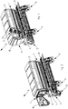
- An agricultural distributor 1 which in the example chosen the Fig. 1 to 8 is designed as a seeder, has a reservoir 2 for storing material to be distributed.
- the storage container 2 is supported by means of supporting elements 3 on the frame 4 of a roller unit 5 assigned to the distributor 1, as in FIG Fig. 1 and 2 shown.
- the lower region of the storage container 2 is designed as a discharge region, in which not shown Outlet openings are arranged.
- About the outlet openings the material to be distributed is delivered to Ausbringierin 6 leading lines 7.
- the Ausbringemia 6 are arranged in the working direction A behind the roller unit 5.
- a plurality of dosing 8 are arranged.
- the output to the lines 7 amount of material to be distributed is set.
- Below the metering at least approximately cylindrically shaped Abwind anyer 9 are arranged, as in the Fig. 2 and 4 is shown.
- a loading web 10 is arranged. Via a rise 11, the loading web 10 is entered, for example, for loading the storage container 2 or for visual inspection of the container level by an operator.
- the rise 11 of the loading web 10 is in a working position 12, shown in FIG Fig. 1 and a calibration and / or maintenance position 13, shown in FIG Fig. 2 , can be moved.
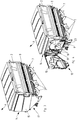
- an operating center 14 On the left in the direction of A side of the reservoir 2, an operating center 14 is arranged. Under a cover 15 pivotable about an at least approximately vertical pivot axis, essential adjustment units 16 of the distributor 1 are combined in the control center 14.
- the cover 15 has a working position 17, shown in FIG Fig. 3 , and a calibration and / or maintenance position 18, shown in FIG Fig. 4 , on.
- the adjustment units 16 combined in the control center 14 include, for example, the adjustment unit of the metering device 8, the bottom flap adjustment unit and / or the adjustment flap adjustment unit.
- the adjustment units typically have a plurality of possible working positions and one calibration and / or maintenance position each.
- the operating center 14 comprises a storage space 19 in which tools required for the calibration and / or maintenance process are stored.
- tools are at least a bucket and a weighing device.
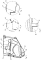
- the inner contour of the pivotally hinged cover 15 is in Fig. 5 shown.
- the inner contour is designed such that it interacts with the adjusting units 16. Is provided by the operator to spend the cover 15 in its working position 17, this is possible only if none of the summarized in the control center 14 adjusting units 16 are in their respective calibration and / or maintenance position.
- Fig. 6 and Fig. 7 the specially shaped areas (i) and (ii) of the inner contour of the cover 15 are shown. They interact with the adjustment units 16 such that the movement of the cover 15 to its working position is blocked when the adjustment units 16 are in their respective calibration and / or maintenance positions.
- the adjusting units 16 abut against the mold parts 20 of the inner contour of the cover 15. Only when the setting units 16 are in a suitable working position for the distribution process, the adjusting units 16 engage in the recesses 21 of the inner contour of the cover 15. The cover 15 can then in spend their job 17.
- Fig. 8 shows the specially shaped area (iii) of the inner contour of the cover 15.
- This area has a recess 22.
- the recess 22 is provided analogously to the manner described for interaction with the suitably shaped calibration box 9.
- the calibration 9 has a calibration and / or maintenance position 23, the Fig. 4 and a working position rotated by 180 ° about a horizontal axis to the calibration and / or maintenance position 23.
- a suitable shaping of the calibration 9 is suitable for engagement in the recess 22.
- a positive connection is only achieved when the calibration 9 is in its working position.
- the cover 15 can be spent only in positive engagement with the calibration box 9 in its working position 17, otherwise the movement of the cover 15 is blocked in its working position 17 by a collision of the inner contour of the cover 15 and the calibration box 9.
Landscapes
- Life Sciences & Earth Sciences (AREA)
- Soil Sciences (AREA)
- Environmental Sciences (AREA)
- Catching Or Destruction (AREA)
Abstract
Landwirtschaftliche Verteilmaschine (1) mit einem auf einem Rahmen (4) abgestützten Vorratsbehälter (2), mit zumindest einem dem Vorratsbehälter zugeordneten, rotierend angetriebenen Dosierorgan(8) , welches das sich im Vorratsbehälter befindliche Material in einstellbaren Mengen in zu Ausbringelementen (6) führende Leitungen (7) einspeist, wobei das zumindest eine Dosierorgan mittels einer Einstelleinheit einstellbar ist, mit zumindest einer dem Dosierorgan zugeordneten Bodenklappe, deren Abstand zum zumindest einen Dosierorgan über eine Bodenklappeneinstelleinheit einstellbar ist, mit zumindest einem Abdrehbehälter (9), welcher unterhalb des zumindest einen Dosierorgans angeordnet und in eine Arbeitsposition und eine Kalibrier- und/oder Wartungsposition (23) verbringbar ist, und/oder mit einer dem zumindest einem Dosierorgan zugeordneten Abdrehklappe, welche in eine Arbeitsposition und eine Kalibrier- und/oder Wartungsposition mittels einer Abdrehklappeneinstelleinheit verbringbar ist, wobei zumindest eine Getriebeeinstelleinheit, die Bodenklappeneinstelleinheit und/oder die Abdrehklappeneinstelleinheit in einem Bedienzentrum (14) zusammengefasst sind und das Bedienzentrum auf einer Seite der Verteilmaschine, vorzugsweise auf der in Arbeitsrichtung (1) linken Seite des Vorratsbehälters angeordnet ist. Um eine Anordnung bereitzustellen, die geeignet ist, die Abdeckung (15) der Einstelleinheiten und gleichzeitig für den Verteilvorgang geeignete Einstellungen der Einstelleinheiten sicherzustellen, ist vorgesehen, dass das Bedienzentrum (14) mittels einer Abdeckung (15) abdeckbar ist und die Abdeckung in eine Kalibrier- und/oder Wartungsposition (18) und eine Arbeitsposition (17) verbringbar ist, wobei die Innenkontur der Abdeckung derart geformt ist, dass die Abdeckung ausschließlich in ihre Arbeitsposition (17) bringbar ist, wenn sich alle im Bedienzentrum (14) zusammengefassten Einstelleinheiten in einer geeigneten Arbeitsposition befinden.An agricultural distribution machine (1) with a storage container (2) supported on a frame (4), with at least one metering member (8) associated with the storage container, which supplies the material in the storage container in adjustable amounts to delivery elements (6) Feeds lines (7), wherein the at least one metering device is adjustable by means of a setting unit, with at least one dosing organ associated bottom flap, the distance to at least one metering via a Bodenklappeneinstelleinheit is adjustable, with at least one calibration (9), which below the at least one Dosing arranged and in a working position and a calibration and / or maintenance position (23) can be brought, and / or with the at least one dosing associated Abdrehklappe, which in a working position and a calibration and / or maintenance position by means of a Abdrehklappeneinstelleinheit is gbar, wherein at least one Getriebeeinstelleinheit, Bodenklappeneinstelleinheit and / or the Abdrehklappeneinstelleinheit in an operating center (14) are combined and the operating center on one side of the distributor, preferably on the left in the working direction (1) side of the reservoir. In order to provide an arrangement which is suitable for securing the cover (15) of the setting units and at the same time settings of the setting units suitable for the distribution operation, it is provided that the operating center (14) can be covered by a cover (15) and the cover is calibrated - And / or maintenance position (18) and a working position (17) can be brought, wherein the inner contour of the cover is shaped such that the cover exclusively in its working position (17) can be brought, if all in the control center (14) combined adjustment units in a suitable working position.
Description
Die Erfindung betrifft eine landwirtschaftliche Verteilmaschine gemäß des Oberbegriffes des Patentanspruches 1.The invention relates to an agricultural distribution machine according to the preamble of claim 1.
Eine derartige Verteilmaschine ist in der
Bei einer derartigen Ausgestaltung ist nachteilig, dass keine Abdeckung des Bedienzentrums vorgesehen ist. Abdeckungen von Einstelleinheiten zum Schutz der Einstelleinheiten beispielsweise vor Verschmutzung oder Witterungseinflüssen sind aus dem Stand der Technik bekannt. Nachteilig bei einer Abdeckung ist, dass ein Bediener der Verteilmaschine die gewählten Einstellungen der Verteilmaschine nur bei geöffneter Abdeckung einsehen kann. Insbesondere beim Wechsel von einem Kalibrier- und/oder Wartungszustand in einen Arbeitszustand der Verteilmaschine kann beispielsweise durch Unachtsamkeit des Bedieners eine Fehlbedienung auftreten. So können irrtümlich Einstelleinheiten in ihrer Kalibrier- und/oder Wartungsposition verbleiben und somit die Durchführung des angestrebten Verteilvorgangs be- und/oder verhindern.In such a configuration is disadvantageous that no cover of the operator center is provided. Covers of setting units for protecting the setting units, for example against contamination or atmospheric influences, are known from the prior art. A disadvantage of a cover is that an operator of the distributor can see the selected settings of the distributor only with open cover. In particular, when changing from a calibration and / or maintenance state to a working state of the distributor machine, for example, by carelessness of the operator, a faulty operation may occur. Thus, adjustment units can erroneously remain in their calibration and / or maintenance position and thus hinder and / or prevent the implementation of the desired distribution process.
Der Erfindung liegt daher die Aufgabe zugrunde, eine Anordnung bereitzustellen, die geeignet ist, die Abdeckung der Einstelleinheiten und gleichzeitig für den Verteilvorgang geeignete Einstellungen der Einstelleinheiten sicherzustellen.The invention is therefore based on the object to provide an arrangement which is suitable to ensure the coverage of the setting units and at the same time for the distribution process suitable settings of the setting units.
Zur erfindungsgemäßen Lösung dieser Aufgabe ist daher vorgesehen, dass das Bedienzentrum mittels einer Abdeckung abdeckbar ist und die Abdeckung in eine Kalibrier- und/oder Wartungsposition und eine Arbeitsposition verbringbar ist, wobei die Innenkontur der Abdeckung derart geformt ist, dass die Abdeckung ausschließlich in ihre Arbeitsposition bringbar ist, wenn sich alle im Bedienzentrum zusammengefassten Einstelleinheiten in einer geeigneten Arbeitsposition befinden.To achieve this object of the invention, it is therefore provided that the operating center can be covered by means of a cover and the cover can be moved to a calibration and / or maintenance position and a working position, the inner contour of the cover being shaped such that the cover is in its working position can be brought if all adjustment units combined in the operating center are in a suitable working position.
Dies hat den Vorteil, dass der Bediener der Verteilmaschine das Bedienzentrum und somit die Einstelleinheiten nur abdecken kann, wenn alle Einstelleinheiten derart eingestellt sind, dass das Durchführen eines Verteilvorgangs möglich ist, sich also die Einstelleinheiten in einer Arbeitsposition befinden. Eine Fehlbedienung etwa durch Unachtsamkeit oder Ablenkung ist nicht möglich. So kann beispielsweise das Bedienzentrum nicht mit der Abdeckung abgedeckt werden, wenn sich die Bodenklappen in Entleerungsposition befinden. Analoges gilt, wenn sich der Abdrehbehälter nicht in seiner Arbeitsposition, sondern in seiner für den Abdrehvorgang notwendigen Kalibrier- und/oder Wartungsposition befindet. In beiden beispielhaften Fällen wird das Verbringen der Abdeckung in ihre Arbeitsposition durch die mit den Einstelleinheiten bzw. mit dem Abdrehbehälter kollidierende Innenkontur der Abdeckung blockiert.This has the advantage that the operator of the distribution machine can cover the operating center and thus the setting units only if all setting units are set such that it is possible to carry out a distribution process, ie if the setting units are in a working position. An incorrect operation, for example due to carelessness or distraction is not possible. For example, the control center can not be covered with the cover when the bottom flaps are in the emptying position. The same applies if the calibration is not in its working position, but in his necessary for the calibration calibration and / or maintenance position. In both exemplary cases, the movement of the cover into its working position is blocked by the inner contour of the cover colliding with the adjustment units or with the calibration container.
Es ist von Vorteil, wenn die Innenkontur der Abdeckung derart veränderlich ausgeführt ist, dass die Abdeckung ausschließlich in ihre Arbeitsposition verbringbar ist, wenn sich alle im Bedienzentrum zusammengefassten Einstelleinheiten in einer speziell eingestellten Arbeitsposition befinden. Der Bediener stellt die mittels der Einstelleinheiten des Bedienzentrums die Verteilmaschine entsprechend dem bevorstehenden Verteilvorgang ein. Dadurch stehen die Einstelleinheiten in einer für den bevorstehenden Verteilvorgang speziellen Arbeitsposition. Durch eine Anpassung der Innenkontur der Abdeckung an diese spezielle Arbeitsposition der Einstelleinheiten des Bedienzentrums, kann das Verbringen der Abdeckung in ihre Arbeitsposition nur erfolgen, wenn die Einstellungen der Einstelleinheiten und der Innenkontur der Abdeckung zueinander passen. Es müssen also die Positionen der Einstelleinheiten und die Innenkontur der Abdeckung bewusst aufeinander abgestimmt werden. Dadurch wird für den Bediener eine zusätzliche Sicherheit erreicht und die Gefahr einer Fehlbedienung beispielsweise durch Unachtsamkeit oder Ablenkung weiter reduziert.It is advantageous if the inner contour of the cover is designed to be variable so that the cover can be brought into its working position only when all the adjustment units combined in the operating center are in a specially set working position. The operator adjusts the distribution machine by means of the setting units of the operating center according to the impending distribution process. As a result, the adjustment units are in a specific work position for the upcoming distribution process. By adapting the inner contour of the cover to this special working position of the adjustment units of the operating center, it is possible to move the cover into its position Working position only take place when the settings of the adjustment units and the inner contour of the cover match each other. It is therefore necessary to deliberately coordinate the positions of the adjustment units and the inner contour of the cover. As a result, additional safety is achieved for the operator and the risk of incorrect operation, for example due to carelessness or distraction, is further reduced.
Eine vorteilhafte Ausgestaltung der Erfindung ist dadurch gegeben, dass die Abdeckung des Bedienzentrums als Abdeckklappe ausgeführt ist und um eine Schwenkachse verschwenkbar am Vorratsbehälter angelenkt ist. Somit kann der Bediener die Abdeckung komfortabel öffnen und schließen. Die Abdeckung muss nicht umständlich vollständig an- oder abgebaut werden. Bei Verwendung einer Abdeckklappe entspricht die Arbeitsposition der geschlossenen Abdeckklappe, die Kalibrier- und/oder Wartungsposition der geöffneten Abdeckklappe.An advantageous embodiment of the invention is given by the fact that the cover of the control center is designed as a cover flap and is pivotable about a pivot axis pivoted on the reservoir. Thus, the operator can easily open and close the cover. The cover does not have to be laboriously completely attached or removed. When using a cover flap corresponds to the working position of the closed cover, the calibration and / or maintenance position of the open cover.
Ein besonderer Vorteil ist gegeben, wenn die Schwenkachse in zumindest annähernd vertikaler oder in zumindest annähernd horizontaler Richtung verläuft. Im Falle einer horizontalen Schwenkachse ist eine Anlenkung der Abdeckung im oberen Bereich des Vorratsbehälters denkbar. Somit kann eine in Kalibrier- und/oder Wartungsposition verschwenkte Abdeckung dem Bediener während des Kalibrier- und/oder Wartungsvorgangs als Schutzdach gegen Sonneneinstrahlung oder Niederschlag dienen. Im Falle einer vertikalen Schwenkachse kann die Abdeckung Tür-artig bewegt werden. Dies hat den Vorteil, dass keine aufwändige Kinematik benötigt wird, die Abdeckung hochzuschwenken und sicher in der hohen Kalibrier- und/oder Wartungsposition zu halten. Es besteht zusätzlich nicht die Gefahr, dass die eine in Kalibrier- und/oder Wartungsposition über dem Bediener befindliche Abdeckung infolge beispielsweise einer Fehlbedienung oder eines Materialversagen auf den Bediener herabfällt.A particular advantage is given if the pivot axis extends in at least approximately vertical or at least approximately horizontal direction. In the case of a horizontal pivot axis an articulation of the cover in the upper region of the reservoir is conceivable. Thus, a tilted in calibration and / or maintenance position cover the operator during the calibration and / or maintenance process as a shelter against sunlight or rainfall serve. In the case of a vertical pivot axis, the cover can be moved door-like. This has the advantage that no complex kinematics is needed to swing the cover up and keep it safely in the high calibration and / or maintenance position. In addition, there is no risk that the one in the calibration and / or maintenance position above the operator cover due to, for example, a misuse or a material failure on the operator drops.
Es ist vorteilhaft, dass das die verschwenkbar am Vorratsbehälter angelenkte Abdeckung in ihrer Kalibrier- und/oder Wartungsposition und/oder in ihrer Arbeitsposition fixierbar ist. Durch die Fixierung in der Arbeitsposition wird erreicht, dass die Einstelleinheiten des Bedienzentrums nicht während eines Verteilvorgangs freiliegen und unerwünscht verstellt werden. Durch die Fixierung in der Kalibrier- und/oder Wartungsposition wird erreicht, dass die Abdeckung nicht während der Durchführung des Kalibiervorgangs durch den Bediener beispielsweise durch einen Windstoß zufällt und somit den Bediener während der Ausführung seiner Aufgaben stört oder gefährdet.It is advantageous that the cover pivotably hinged to the reservoir can be fixed in its calibration and / or maintenance position and / or in its working position. The fixation in the working position ensures that the adjustment units of the operating center are not exposed during a distribution process and are adjusted undesirably. Due to the fixation in the calibration and / or maintenance position is achieved that the cover does not fall during the execution of the calibration process by the operator, for example by a gust of wind and thus disturbs or endangers the operator while performing his duties.
Für den Bedienkomfort der Verteilmaschine ist es vorteilhaft, dass das Bedienzentrum Stauraum zur Aufbewahrung von Werkzeugen aufweist. Somit sind die im Bedienzentrum aufbewahrten Werkzeuge vor Verschmutzungen und/oder Witterungseinflüssen geschützt. Zudem wird die Verlustgefahr durch die Aufbewahrung in einem überwiegend geschlossen gehaltenen Stauraum deutlich reduziert. Wesentlicher Vorteil dieser Ausgestaltung ist die Zugänglichkeit der Werkzeuge. Werden sie am Ort des Kalibrier- und/oder Wartungsvorgangs aufbewahrt, sind die benötigten Werkzeuge durch den den Kalibrier- und/oder Wartungsvorgang durchführenden Bediener während des Kalibrier- und/oder Wartungsvorgangs jederzeit leicht erreichbar.For ease of use of the distributor, it is advantageous that the control center has storage space for storing tools. Thus, the tools stored in the control center are protected against contamination and / or weathering. In addition, the risk of loss due to storage in a largely closed storage space is significantly reduced. The essential advantage of this embodiment is the accessibility of the tools. When stored at the location of the calibration and / or maintenance operation, the tools required by the operator performing the calibration and / or maintenance operation are easily accessible at any time during the calibration and / or maintenance process.
Die wesentlichen für einen Kalibrier- und/oder Wartungsvorgang benötigten Werkzeuge sind der oder die Abdrehbehälter sowie eine zum Wiegen der Abdrehbehälter vorgesehene Wiegevorrichtung. Daher ist es von Vorteil, dass im Stauraum des Bedienzentrums zumindest der Abdrehbehälter und eine Wiegeeinrichtung gelagert sind.The essential tools required for a calibration and / or maintenance operation are the calibration container or a weighing device provided for weighing the calibration container. It is therefore advantageous that at least the calibration container and a weighing device are mounted in the storage space of the operator control center.
Typische Verteilmaschinen weisen oberhalb der Ausbringelemente einen Ladesteg auf. Dieser dient dem Beladen des Vorratsbehälters und/oder einer Kontrolle der Beladung und/oder des Füllstandes des Vorratsbehälters. Damit ein Bediener möglichst kurze Laufwege hat, umfasst der Ladesteg üblicherweise auf der in Arbeitsrichtung linken Seite des Vorratsbehälters einen Aufstieg. Der Aufstieg weist eine Arbeitsposition und eine Kalibrier- und/oder Wartungsposition auf und ist zwischen beiden Positionen verbringbar.Typical distribution machines have a loading web above the dispensing elements. This is used to load the reservoir and / or a control of the loading and / or the level of the reservoir. So that an operator has the shortest paths possible, the loading web usually comprises an ascent on the left side of the storage container in the working direction. The rise has a working position and a calibration and / or maintenance position and can be moved between the two positions.
Es ist vorteilhaft, dass der Aufstieg in seiner Kalibrier- und/oder Wartungsposition ein Befestigungselement aufweist, an dem eine Wiegeeinrichtung für den Abdrehbehälter befestigbar ist. Dadurch ist dem Bediener eine komfortable Durchführung des gesamten Kalibrier- und/oder Wartungsvorgangs möglich. Alle für den Kalibrier- und/oder Wartungsvorgang notwendigen Vorrichtung en sind im Bereich und/oder in der Nähe des Bedienzentrums angeordnet. Zudem ist bei einem ortsfest befestigten Befestigungselement für die Wiegeeinrichtung eine gute Vergleichbarkeit der Wiegeergebnisse gegeben.It is advantageous that the rise in its calibration and / or maintenance position has a fastening element to which a weighing device for the calibration container can be fastened. As a result, the operator is able to comfortably carry out the entire calibration and / or maintenance process. All for the Calibration and / or maintenance process necessary device s are arranged in the area and / or in the vicinity of the control center. In addition, in a fixedly fixed fastening element for the weighing device a good comparability of the weighing results is given.
Weitere Einzelheiten der Erfindung sind der Beispielsbeschreibung und den Zeichnungen zu entnehmen. Die Zeichnungen zeigen
- Fig.1
- wesentliche Teile einer landwirtschaftlichen Verteilmaschine in perspektivischer Ansicht von schräg hinten,
- Fig.2
- wesentlicher Teile einer landwirtschaftlichen Verteilmaschine mit geöffneter Abdeckung in perspektivischer Ansicht von schräg hinten,
- Fig.3
- den Vorratsbehälter einer landwirtschaftlichen Verteilmaschine in perspektivischer Ansicht von schräg hinten,
- Fig.4
- den Vorratsbehälter einer landwirtschaftlichen Verteilmaschine mit geöffneter Abdeckung in perspektivischer Ansicht von schräg hinten,
- Fig.5
- die Innenkontur der Abdeckung in einer Ansicht in Draufsicht,
- Fig.6
- eine vergrößerte Darstellung des Bereichs (i) der
Fig. 5 , - Fig.7
- eine vergrößerte Darstellung des Bereichs (ii) der
Fig. 5 und - Fig.8
- eine vergrößerte Darstellung des Bereichs (iii) der
Fig. 5 .
- Fig.1
- essential parts of a agricultural distributor in a perspective view obliquely from behind,
- Fig.2
- essential parts of an agricultural distributor with open cover in a perspective view obliquely from behind,
- Figure 3
- the reservoir of a agricultural distributor in a perspective view obliquely from behind,
- Figure 4
- the reservoir of a agricultural distributor with open cover in a perspective view obliquely from behind
- Figure 5
- the inner contour of the cover in a view in plan view,
- Figure 6
- an enlarged view of the area (i) of
Fig. 5 . - Figure 7
- an enlarged view of the area (ii) of
Fig. 5 and - Figure 8
- an enlarged view of the area (iii) of
Fig. 5 ,
Eine landwirtschaftliche Verteilmaschine 1, welche im gewählten Beispiel der
Oberhalb der Ausbringelemente 6 ist ein Ladesteg 10 angeordnet. Über einen Aufstieg 11 wird der Ladesteg 10 beispielsweise zum Beladen des Vorratsbehälters 2 oder zur Sichtkontrolle des Behälterfüllstandes durch einen Bediener betreten. Der Aufstieg 11 des Ladestegs 10 ist in eine Arbeitsposition 12, gezeigt in
Auf der in Arbeitsrichtung A linken Seite des Vorratsbehälters 2 ist ein Bedienzentrum 14 angeordnet. Unter einer um eine zumindest annähernd vertikale Schwenkachse verschwenkbaren Abdeckung 15 sind in dem Bedienzentrum 14 wesentliche Einstelleinheiten 16 der Verteilmaschine 1 zusammengefasst. Die Abdeckung 15 weist eine Arbeitsposition 17, gezeigt in
Die im Bedienzentrum 14 zusammengefassten Einstelleinheiten 16 umfassen beispielsweise die Einstelleinheit des Dosierorgans 8, die Bodenklappeneinstelleinheit und/oder die Abdrehklappeneinstelleinheit. Die Einstelleinheiten weisen typischerweise eine Vielzahl möglicher Arbeitspositionen und je eine Kalibrier- und/oder Wartungsposition auf.The adjustment units 16 combined in the
Zudem umfasst das Bedienzentrum 14 einen Stauraum 19, in dem für den Kalibrier- und/oder Wartungsprozess benötigte Werkzeuge gelagert werden. Derartige Werkzeuge sind zumindest ein Eimer und eine Wiegeeinrichtung.In addition, the
Die Innenkontur der verschwenkbar angelenkten Abdeckung 15 ist in
In
Claims (8)
Priority Applications (1)
| Application Number | Priority Date | Filing Date | Title |
|---|---|---|---|
| PL17401067T PL3262913T3 (en) | 2016-07-01 | 2017-06-27 | Agricultural spreader machine with operating centre |
Applications Claiming Priority (1)
| Application Number | Priority Date | Filing Date | Title |
|---|---|---|---|
| DE102016112059.6A DE102016112059A1 (en) | 2016-07-01 | 2016-07-01 | Agricultural distributor with control center |
Publications (2)
| Publication Number | Publication Date |
|---|---|
| EP3262913A1 true EP3262913A1 (en) | 2018-01-03 |
| EP3262913B1 EP3262913B1 (en) | 2019-03-13 |
Family
ID=59363077
Family Applications (1)
| Application Number | Title | Priority Date | Filing Date |
|---|---|---|---|
| EP17401067.8A Active EP3262913B1 (en) | 2016-07-01 | 2017-06-27 | Agricultural spreader machine with operating centre |
Country Status (3)
| Country | Link |
|---|---|
| EP (1) | EP3262913B1 (en) |
| DE (1) | DE102016112059A1 (en) |
| PL (1) | PL3262913T3 (en) |
Families Citing this family (2)
| Publication number | Priority date | Publication date | Assignee | Title |
|---|---|---|---|---|
| DE102019122915A1 (en) * | 2019-08-27 | 2021-03-04 | Horsch Maschinen Gmbh | Storage container with integrated lighting device and / or integrated drawer |
| US11825764B2 (en) * | 2020-07-14 | 2023-11-28 | Greenvalley Equipment (2009) Inc. | Collection device for meter calibration of air seeder tanks |
Citations (3)
| Publication number | Priority date | Publication date | Assignee | Title |
|---|---|---|---|---|
| DE29907696U1 (en) * | 1999-04-30 | 2000-09-07 | Amazonen Werke Dreyer H | Continuously variable transmission for agricultural distribution machines in particular |
| DE102006011197A1 (en) | 2006-03-10 | 2007-09-13 | Rabe Agri Gmbh | seeder |
| EP2807915A1 (en) * | 2013-05-28 | 2014-12-03 | Amazonen-Werke H. Dreyer GmbH & Co. KG | Agricultural distributor |
-
2016
- 2016-07-01 DE DE102016112059.6A patent/DE102016112059A1/en not_active Withdrawn
-
2017
- 2017-06-27 EP EP17401067.8A patent/EP3262913B1/en active Active
- 2017-06-27 PL PL17401067T patent/PL3262913T3/en unknown
Patent Citations (3)
| Publication number | Priority date | Publication date | Assignee | Title |
|---|---|---|---|---|
| DE29907696U1 (en) * | 1999-04-30 | 2000-09-07 | Amazonen Werke Dreyer H | Continuously variable transmission for agricultural distribution machines in particular |
| DE102006011197A1 (en) | 2006-03-10 | 2007-09-13 | Rabe Agri Gmbh | seeder |
| EP2807915A1 (en) * | 2013-05-28 | 2014-12-03 | Amazonen-Werke H. Dreyer GmbH & Co. KG | Agricultural distributor |
Also Published As
| Publication number | Publication date |
|---|---|
| DE102016112059A1 (en) | 2018-01-04 |
| EP3262913B1 (en) | 2019-03-13 |
| PL3262913T3 (en) | 2019-09-30 |
Similar Documents
| Publication | Publication Date | Title |
|---|---|---|
| EP3165091B1 (en) | Regulating or control system for an agricultural machine | |
| EP3262913B1 (en) | Agricultural spreader machine with operating centre | |
| DE10231813A1 (en) | Dosing system for powder pigments | |
| EP3262912B1 (en) | Agricultural spreader machine with cover | |
| WO2013131640A2 (en) | Method and device for removing and/or installing a fire extinguisher in an airplane | |
| DE1782544B1 (en) | ROTARY TEDERS | |
| EP2000016B1 (en) | Pulled agricultural sowing machine | |
| DE2207484B2 (en) | Method for controlling the amount of material to be ground in a grinding chamber of a ball mill tube and device for carrying out this method | |
| EP3272215B1 (en) | Agricultural field spraying device | |
| DE102016118444A1 (en) | Method and spraying device for applying a spraying liquid on an agricultural surface | |
| EP2364583B1 (en) | Agricultural spreader | |
| EP3666406B1 (en) | Washing machine | |
| DE102010000298A1 (en) | Zweischeibenstreuer | |
| EP2353358B1 (en) | Agricultural device | |
| EP2353360B1 (en) | Centrifugal spreader | |
| EP2353359B1 (en) | Agricultural device | |
| DE102012007855B4 (en) | Modular system for manipulating tools for mobile machines | |
| DE102017116453B3 (en) | Agricultural distributor | |
| DE4419436C1 (en) | Self-propelled combine harvester with inclined conveyor channel | |
| DE102016014360A1 (en) | Truck mixer | |
| DE2535701A1 (en) | Machine for cutting, loading, transporting and distributing silage - has hexagonal prismatic cutter drum with helical blade pattern, and container with auger | |
| DE4335255C2 (en) | Device for handling in particular pharmaceutical bulk goods | |
| DE949816C (en) | Machine for shoveling, conveying and bagging bulk goods such as coal | |
| DE19652373C1 (en) | Liquid distributors, in particular liquid manure spreaders | |
| DE2921895B2 (en) | Trapezoidal base plate |
Legal Events
| Date | Code | Title | Description |
|---|---|---|---|
| PUAI | Public reference made under article 153(3) epc to a published international application that has entered the european phase |
Free format text: ORIGINAL CODE: 0009012 |
|
| STAA | Information on the status of an ep patent application or granted ep patent |
Free format text: STATUS: THE APPLICATION HAS BEEN PUBLISHED |
|
| AK | Designated contracting states |
Kind code of ref document: A1 Designated state(s): AL AT BE BG CH CY CZ DE DK EE ES FI FR GB GR HR HU IE IS IT LI LT LU LV MC MK MT NL NO PL PT RO RS SE SI SK SM TR |
|
| AX | Request for extension of the european patent |
Extension state: BA ME |
|
| STAA | Information on the status of an ep patent application or granted ep patent |
Free format text: STATUS: REQUEST FOR EXAMINATION WAS MADE |
|
| 17P | Request for examination filed |
Effective date: 20180525 |
|
| RBV | Designated contracting states (corrected) |
Designated state(s): AL AT BE BG CH CY CZ DE DK EE ES FI FR GB GR HR HU IE IS IT LI LT LU LV MC MK MT NL NO PL PT RO RS SE SI SK SM TR |
|
| GRAP | Despatch of communication of intention to grant a patent |
Free format text: ORIGINAL CODE: EPIDOSNIGR1 |
|
| STAA | Information on the status of an ep patent application or granted ep patent |
Free format text: STATUS: GRANT OF PATENT IS INTENDED |
|
| INTG | Intention to grant announced |
Effective date: 20181005 |
|
| GRAS | Grant fee paid |
Free format text: ORIGINAL CODE: EPIDOSNIGR3 |
|
| GRAA | (expected) grant |
Free format text: ORIGINAL CODE: 0009210 |
|
| STAA | Information on the status of an ep patent application or granted ep patent |
Free format text: STATUS: THE PATENT HAS BEEN GRANTED |
|
| AK | Designated contracting states |
Kind code of ref document: B1 Designated state(s): AL AT BE BG CH CY CZ DE DK EE ES FI FR GB GR HR HU IE IS IT LI LT LU LV MC MK MT NL NO PL PT RO RS SE SI SK SM TR |
|
| REG | Reference to a national code |
Ref country code: GB Ref legal event code: FG4D Free format text: NOT ENGLISH |
|
| REG | Reference to a national code |
Ref country code: CH Ref legal event code: EP Ref country code: AT Ref legal event code: REF Ref document number: 1106408 Country of ref document: AT Kind code of ref document: T Effective date: 20190315 |
|
| REG | Reference to a national code |
Ref country code: IE Ref legal event code: FG4D Free format text: LANGUAGE OF EP DOCUMENT: GERMAN |
|
| REG | Reference to a national code |
Ref country code: DE Ref legal event code: R096 Ref document number: 502017000925 Country of ref document: DE |
|
| REG | Reference to a national code |
Ref country code: SE Ref legal event code: TRGR |
|
| REG | Reference to a national code |
Ref country code: NL Ref legal event code: MP Effective date: 20190313 |
|
| REG | Reference to a national code |
Ref country code: LT Ref legal event code: MG4D |
|
| PG25 | Lapsed in a contracting state [announced via postgrant information from national office to epo] |
Ref country code: LT Free format text: LAPSE BECAUSE OF FAILURE TO SUBMIT A TRANSLATION OF THE DESCRIPTION OR TO PAY THE FEE WITHIN THE PRESCRIBED TIME-LIMIT Effective date: 20190313 Ref country code: FI Free format text: LAPSE BECAUSE OF FAILURE TO SUBMIT A TRANSLATION OF THE DESCRIPTION OR TO PAY THE FEE WITHIN THE PRESCRIBED TIME-LIMIT Effective date: 20190313 Ref country code: NO Free format text: LAPSE BECAUSE OF FAILURE TO SUBMIT A TRANSLATION OF THE DESCRIPTION OR TO PAY THE FEE WITHIN THE PRESCRIBED TIME-LIMIT Effective date: 20190613 |
|
| PG25 | Lapsed in a contracting state [announced via postgrant information from national office to epo] |
Ref country code: RS Free format text: LAPSE BECAUSE OF FAILURE TO SUBMIT A TRANSLATION OF THE DESCRIPTION OR TO PAY THE FEE WITHIN THE PRESCRIBED TIME-LIMIT Effective date: 20190313 Ref country code: GR Free format text: LAPSE BECAUSE OF FAILURE TO SUBMIT A TRANSLATION OF THE DESCRIPTION OR TO PAY THE FEE WITHIN THE PRESCRIBED TIME-LIMIT Effective date: 20190614 Ref country code: BG Free format text: LAPSE BECAUSE OF FAILURE TO SUBMIT A TRANSLATION OF THE DESCRIPTION OR TO PAY THE FEE WITHIN THE PRESCRIBED TIME-LIMIT Effective date: 20190613 Ref country code: LV Free format text: LAPSE BECAUSE OF FAILURE TO SUBMIT A TRANSLATION OF THE DESCRIPTION OR TO PAY THE FEE WITHIN THE PRESCRIBED TIME-LIMIT Effective date: 20190313 Ref country code: NL Free format text: LAPSE BECAUSE OF FAILURE TO SUBMIT A TRANSLATION OF THE DESCRIPTION OR TO PAY THE FEE WITHIN THE PRESCRIBED TIME-LIMIT Effective date: 20190313 Ref country code: HR Free format text: LAPSE BECAUSE OF FAILURE TO SUBMIT A TRANSLATION OF THE DESCRIPTION OR TO PAY THE FEE WITHIN THE PRESCRIBED TIME-LIMIT Effective date: 20190313 |
|
| PG25 | Lapsed in a contracting state [announced via postgrant information from national office to epo] |
Ref country code: RO Free format text: LAPSE BECAUSE OF FAILURE TO SUBMIT A TRANSLATION OF THE DESCRIPTION OR TO PAY THE FEE WITHIN THE PRESCRIBED TIME-LIMIT Effective date: 20190313 Ref country code: CZ Free format text: LAPSE BECAUSE OF FAILURE TO SUBMIT A TRANSLATION OF THE DESCRIPTION OR TO PAY THE FEE WITHIN THE PRESCRIBED TIME-LIMIT Effective date: 20190313 Ref country code: ES Free format text: LAPSE BECAUSE OF FAILURE TO SUBMIT A TRANSLATION OF THE DESCRIPTION OR TO PAY THE FEE WITHIN THE PRESCRIBED TIME-LIMIT Effective date: 20190313 Ref country code: EE Free format text: LAPSE BECAUSE OF FAILURE TO SUBMIT A TRANSLATION OF THE DESCRIPTION OR TO PAY THE FEE WITHIN THE PRESCRIBED TIME-LIMIT Effective date: 20190313 Ref country code: SK Free format text: LAPSE BECAUSE OF FAILURE TO SUBMIT A TRANSLATION OF THE DESCRIPTION OR TO PAY THE FEE WITHIN THE PRESCRIBED TIME-LIMIT Effective date: 20190313 Ref country code: PT Free format text: LAPSE BECAUSE OF FAILURE TO SUBMIT A TRANSLATION OF THE DESCRIPTION OR TO PAY THE FEE WITHIN THE PRESCRIBED TIME-LIMIT Effective date: 20190713 Ref country code: AL Free format text: LAPSE BECAUSE OF FAILURE TO SUBMIT A TRANSLATION OF THE DESCRIPTION OR TO PAY THE FEE WITHIN THE PRESCRIBED TIME-LIMIT Effective date: 20190313 |
|
| PG25 | Lapsed in a contracting state [announced via postgrant information from national office to epo] |
Ref country code: SM Free format text: LAPSE BECAUSE OF FAILURE TO SUBMIT A TRANSLATION OF THE DESCRIPTION OR TO PAY THE FEE WITHIN THE PRESCRIBED TIME-LIMIT Effective date: 20190313 |
|
| REG | Reference to a national code |
Ref country code: DE Ref legal event code: R097 Ref document number: 502017000925 Country of ref document: DE |
|
| PG25 | Lapsed in a contracting state [announced via postgrant information from national office to epo] |
Ref country code: IS Free format text: LAPSE BECAUSE OF FAILURE TO SUBMIT A TRANSLATION OF THE DESCRIPTION OR TO PAY THE FEE WITHIN THE PRESCRIBED TIME-LIMIT Effective date: 20190713 |
|
| PLBE | No opposition filed within time limit |
Free format text: ORIGINAL CODE: 0009261 |
|
| STAA | Information on the status of an ep patent application or granted ep patent |
Free format text: STATUS: NO OPPOSITION FILED WITHIN TIME LIMIT |
|
| PG25 | Lapsed in a contracting state [announced via postgrant information from national office to epo] |
Ref country code: MC Free format text: LAPSE BECAUSE OF FAILURE TO SUBMIT A TRANSLATION OF THE DESCRIPTION OR TO PAY THE FEE WITHIN THE PRESCRIBED TIME-LIMIT Effective date: 20190313 Ref country code: DK Free format text: LAPSE BECAUSE OF FAILURE TO SUBMIT A TRANSLATION OF THE DESCRIPTION OR TO PAY THE FEE WITHIN THE PRESCRIBED TIME-LIMIT Effective date: 20190313 |
|
| 26N | No opposition filed |
Effective date: 20191216 |
|
| PG25 | Lapsed in a contracting state [announced via postgrant information from national office to epo] |
Ref country code: SI Free format text: LAPSE BECAUSE OF FAILURE TO SUBMIT A TRANSLATION OF THE DESCRIPTION OR TO PAY THE FEE WITHIN THE PRESCRIBED TIME-LIMIT Effective date: 20190313 |
|
| REG | Reference to a national code |
Ref country code: BE Ref legal event code: MM Effective date: 20190630 |
|
| PG25 | Lapsed in a contracting state [announced via postgrant information from national office to epo] |
Ref country code: TR Free format text: LAPSE BECAUSE OF FAILURE TO SUBMIT A TRANSLATION OF THE DESCRIPTION OR TO PAY THE FEE WITHIN THE PRESCRIBED TIME-LIMIT Effective date: 20190313 |
|
| PG25 | Lapsed in a contracting state [announced via postgrant information from national office to epo] |
Ref country code: IE Free format text: LAPSE BECAUSE OF NON-PAYMENT OF DUE FEES Effective date: 20190627 |
|
| PG25 | Lapsed in a contracting state [announced via postgrant information from national office to epo] |
Ref country code: BE Free format text: LAPSE BECAUSE OF NON-PAYMENT OF DUE FEES Effective date: 20190630 Ref country code: LU Free format text: LAPSE BECAUSE OF NON-PAYMENT OF DUE FEES Effective date: 20190627 |
|
| REG | Reference to a national code |
Ref country code: CH Ref legal event code: PL |
|
| PG25 | Lapsed in a contracting state [announced via postgrant information from national office to epo] |
Ref country code: CH Free format text: LAPSE BECAUSE OF NON-PAYMENT OF DUE FEES Effective date: 20200630 Ref country code: LI Free format text: LAPSE BECAUSE OF NON-PAYMENT OF DUE FEES Effective date: 20200630 |
|
| REG | Reference to a national code |
Ref country code: DE Ref legal event code: R081 Ref document number: 502017000925 Country of ref document: DE Owner name: AMAZONEN-WERKE H. DREYER SE & CO. KG, DE Free format text: FORMER OWNER: AMAZONEN-WERKE H. DREYER GMBH & CO. KG, 49205 HASBERGEN, DE |
|
| PG25 | Lapsed in a contracting state [announced via postgrant information from national office to epo] |
Ref country code: CY Free format text: LAPSE BECAUSE OF FAILURE TO SUBMIT A TRANSLATION OF THE DESCRIPTION OR TO PAY THE FEE WITHIN THE PRESCRIBED TIME-LIMIT Effective date: 20190313 |
|
| PG25 | Lapsed in a contracting state [announced via postgrant information from national office to epo] |
Ref country code: MT Free format text: LAPSE BECAUSE OF FAILURE TO SUBMIT A TRANSLATION OF THE DESCRIPTION OR TO PAY THE FEE WITHIN THE PRESCRIBED TIME-LIMIT Effective date: 20190313 Ref country code: HU Free format text: LAPSE BECAUSE OF FAILURE TO SUBMIT A TRANSLATION OF THE DESCRIPTION OR TO PAY THE FEE WITHIN THE PRESCRIBED TIME-LIMIT; INVALID AB INITIO Effective date: 20170627 |
|
| GBPC | Gb: european patent ceased through non-payment of renewal fee |
Effective date: 20210627 |
|
| PG25 | Lapsed in a contracting state [announced via postgrant information from national office to epo] |
Ref country code: GB Free format text: LAPSE BECAUSE OF NON-PAYMENT OF DUE FEES Effective date: 20210627 |
|
| PG25 | Lapsed in a contracting state [announced via postgrant information from national office to epo] |
Ref country code: MK Free format text: LAPSE BECAUSE OF FAILURE TO SUBMIT A TRANSLATION OF THE DESCRIPTION OR TO PAY THE FEE WITHIN THE PRESCRIBED TIME-LIMIT Effective date: 20190313 |
|
| PGFP | Annual fee paid to national office [announced via postgrant information from national office to epo] |
Ref country code: SE Payment date: 20230314 Year of fee payment: 7 |
|
| P01 | Opt-out of the competence of the unified patent court (upc) registered |
Effective date: 20230523 |
|
| PGFP | Annual fee paid to national office [announced via postgrant information from national office to epo] |
Ref country code: IT Payment date: 20230510 Year of fee payment: 7 Ref country code: FR Payment date: 20230510 Year of fee payment: 7 Ref country code: DE Payment date: 20230502 Year of fee payment: 7 |
|
| PGFP | Annual fee paid to national office [announced via postgrant information from national office to epo] |
Ref country code: PL Payment date: 20230417 Year of fee payment: 7 Ref country code: AT Payment date: 20230525 Year of fee payment: 7 |