EP3261864B1 - Verfahren und system zur höhenmessung in einem fahrzeug - Google Patents
Verfahren und system zur höhenmessung in einem fahrzeug Download PDFInfo
- Publication number
- EP3261864B1 EP3261864B1 EP16703435.4A EP16703435A EP3261864B1 EP 3261864 B1 EP3261864 B1 EP 3261864B1 EP 16703435 A EP16703435 A EP 16703435A EP 3261864 B1 EP3261864 B1 EP 3261864B1
- Authority
- EP
- European Patent Office
- Prior art keywords
- transmitter
- signal
- receiver
- vehicle
- electromagnetic field
- Prior art date
- Legal status (The legal status is an assumption and is not a legal conclusion. Google has not performed a legal analysis and makes no representation as to the accuracy of the status listed.)
- Active
Links
Images

Classifications
-
- B—PERFORMING OPERATIONS; TRANSPORTING
- B60—VEHICLES IN GENERAL
- B60G—VEHICLE SUSPENSION ARRANGEMENTS
- B60G17/00—Resilient suspensions having means for adjusting the spring or vibration-damper characteristics, for regulating the distance between a supporting surface and a sprung part of vehicle or for locking suspension during use to meet varying vehicular or surface conditions, e.g. due to speed or load
- B60G17/015—Resilient suspensions having means for adjusting the spring or vibration-damper characteristics, for regulating the distance between a supporting surface and a sprung part of vehicle or for locking suspension during use to meet varying vehicular or surface conditions, e.g. due to speed or load the regulating means comprising electric or electronic elements
- B60G17/019—Resilient suspensions having means for adjusting the spring or vibration-damper characteristics, for regulating the distance between a supporting surface and a sprung part of vehicle or for locking suspension during use to meet varying vehicular or surface conditions, e.g. due to speed or load the regulating means comprising electric or electronic elements characterised by the type of sensor or the arrangement thereof
-
- B—PERFORMING OPERATIONS; TRANSPORTING
- B60—VEHICLES IN GENERAL
- B60G—VEHICLE SUSPENSION ARRANGEMENTS
- B60G17/00—Resilient suspensions having means for adjusting the spring or vibration-damper characteristics, for regulating the distance between a supporting surface and a sprung part of vehicle or for locking suspension during use to meet varying vehicular or surface conditions, e.g. due to speed or load
- B60G17/015—Resilient suspensions having means for adjusting the spring or vibration-damper characteristics, for regulating the distance between a supporting surface and a sprung part of vehicle or for locking suspension during use to meet varying vehicular or surface conditions, e.g. due to speed or load the regulating means comprising electric or electronic elements
- B60G17/0152—Resilient suspensions having means for adjusting the spring or vibration-damper characteristics, for regulating the distance between a supporting surface and a sprung part of vehicle or for locking suspension during use to meet varying vehicular or surface conditions, e.g. due to speed or load the regulating means comprising electric or electronic elements characterised by the action on a particular type of suspension unit
- B60G17/0155—Resilient suspensions having means for adjusting the spring or vibration-damper characteristics, for regulating the distance between a supporting surface and a sprung part of vehicle or for locking suspension during use to meet varying vehicular or surface conditions, e.g. due to speed or load the regulating means comprising electric or electronic elements characterised by the action on a particular type of suspension unit pneumatic unit
-
- G—PHYSICS
- G01—MEASURING; TESTING
- G01B—MEASURING LENGTH, THICKNESS OR SIMILAR LINEAR DIMENSIONS; MEASURING ANGLES; MEASURING AREAS; MEASURING IRREGULARITIES OF SURFACES OR CONTOURS
- G01B7/00—Measuring arrangements characterised by the use of electric or magnetic techniques
- G01B7/14—Measuring arrangements characterised by the use of electric or magnetic techniques for measuring distance or clearance between spaced objects or spaced apertures
-
- G—PHYSICS
- G01—MEASURING; TESTING
- G01B—MEASURING LENGTH, THICKNESS OR SIMILAR LINEAR DIMENSIONS; MEASURING ANGLES; MEASURING AREAS; MEASURING IRREGULARITIES OF SURFACES OR CONTOURS
- G01B7/00—Measuring arrangements characterised by the use of electric or magnetic techniques
- G01B7/30—Measuring arrangements characterised by the use of electric or magnetic techniques for measuring angles or tapers; for testing the alignment of axes
- G01B7/315—Measuring arrangements characterised by the use of electric or magnetic techniques for measuring angles or tapers; for testing the alignment of axes for testing wheel alignment
-
- B—PERFORMING OPERATIONS; TRANSPORTING
- B60—VEHICLES IN GENERAL
- B60G—VEHICLE SUSPENSION ARRANGEMENTS
- B60G2202/00—Indexing codes relating to the type of spring, damper or actuator
- B60G2202/10—Type of spring
- B60G2202/15—Fluid spring
- B60G2202/152—Pneumatic spring
-
- B—PERFORMING OPERATIONS; TRANSPORTING
- B60—VEHICLES IN GENERAL
- B60G—VEHICLE SUSPENSION ARRANGEMENTS
- B60G2204/00—Indexing codes related to suspensions per se or to auxiliary parts
- B60G2204/10—Mounting of suspension elements
- B60G2204/11—Mounting of sensors thereon
- B60G2204/111—Mounting of sensors thereon on pneumatic springs
-
- B—PERFORMING OPERATIONS; TRANSPORTING
- B60—VEHICLES IN GENERAL
- B60G—VEHICLE SUSPENSION ARRANGEMENTS
- B60G2300/00—Indexing codes relating to the type of vehicle
- B60G2300/02—Trucks; Load vehicles
- B60G2300/026—Heavy duty trucks
-
- B—PERFORMING OPERATIONS; TRANSPORTING
- B60—VEHICLES IN GENERAL
- B60G—VEHICLE SUSPENSION ARRANGEMENTS
- B60G2300/00—Indexing codes relating to the type of vehicle
- B60G2300/04—Trailers
- B60G2300/042—Semi-trailers
-
- B—PERFORMING OPERATIONS; TRANSPORTING
- B60—VEHICLES IN GENERAL
- B60G—VEHICLE SUSPENSION ARRANGEMENTS
- B60G2400/00—Indexing codes relating to detected, measured or calculated conditions or factors
- B60G2400/25—Stroke; Height; Displacement
- B60G2400/252—Stroke; Height; Displacement vertical
-
- B—PERFORMING OPERATIONS; TRANSPORTING
- B60—VEHICLES IN GENERAL
- B60G—VEHICLE SUSPENSION ARRANGEMENTS
- B60G2401/00—Indexing codes relating to the type of sensors based on the principle of their operation
- B60G2401/17—Magnetic/Electromagnetic
-
- B—PERFORMING OPERATIONS; TRANSPORTING
- B60—VEHICLES IN GENERAL
- B60G—VEHICLE SUSPENSION ARRANGEMENTS
- B60G2401/00—Indexing codes relating to the type of sensors based on the principle of their operation
- B60G2401/17—Magnetic/Electromagnetic
- B60G2401/176—Radio or audio sensitive means, e.g. Ultrasonic
Definitions
- the invention relates to a method for height measurement in a vehicle by determining the distance between the vehicle chassis and the vehicle axle or related parts, a first device with a first transmitter and first receiver on the one hand and a second device with a second transmitter and second receiver on the other hand interacting, with the first The transmitter generates an electromagnetic field, the second receiver detects the electromagnetic field, the second device with the second transmitter generates and transmits a signal from the detected field which correlates with the distance from the first transmitter to the second receiver, and the first device with the first Receiver receives the signal.
- the invention relates to a system for height measurement, an electronically controlled air suspension with the system and a vehicle with the system. Commercial vehicles with air suspension are usually equipped with an automatic level control. A loaded vehicle is thereby the same height as an unloaded vehicle, i. This means that the distance between the vehicle chassis and the vehicle axle is no smaller when the vehicle is loaded than when the vehicle is unloaded.
- Part of the automatic level control is often a mechanical coupling between the vehicle chassis and the vehicle axle, namely a coupling rod that is usually connected to a displacement sensor for detecting the height difference.
- a coupling rod that is usually connected to a displacement sensor for detecting the height difference.
- compressed air valves for ventilating or venting the air suspension are activated via the associated vehicle electronics.
- the coupling rod When the vehicle is being loaded, press the vehicle chassis on the vehicle axle, the distance is reduced, the movement of the coupling rod causes a ventilation valve to open so that the vehicle chassis is raised again to its original height.
- the level control takes place in the opposite direction when the vehicle is unloaded.
- the height determination is mechanically complex due to the combination of the coupling rod / displacement sensor and the connection to the electronically controlled air suspension.
- the change in the distance between the vehicle chassis and the vehicle axle is decisive for level control.
- This distance can be measured directly or via auxiliary points, i.e. via parts connected to the vehicle chassis and vehicle axle, such as a chassis frame as part of the vehicle chassis on the one hand and parts of the wheel suspension that belongs to the vehicle axle on the other.
- a distance display system for air springs is known, with a transceiver on one side and a transponder with antenna on the other side.
- a backscatter modulation is emitted with the antenna, the modulation of the amplitude changing depending on the distance.
- an air-sprung chassis with level measuring device with an active sensor unit and a passive element.
- the active sensor unit supplies the passive element via a alternating magnetic field with energy, the passive element responds to a request from the active sensor unit and the active sensor unit evaluates the field strength of the response from the passive element.
- US 2007/0171036 A1 discloses a height measurement in an air spring of a vehicle.
- An electromagnetic wave is transmitted via a first transmitter-receiver pair.
- a second electromagnetic wave is generated from this in relation to the distance between the transmitter and receiver.
- the second electromagnetic wave is transmitted in the opposite direction to the first electromagnetic wave via a second transmitter-receiver pair.
- the object of the present invention is to create a simple and safe alternative to the existing methods.
- the replacement of the mechanical coupling rod and the connection to an electronically controlled air suspension should be possible.
- the method according to the invention has the features of claim 1. It is provided that the first transmitter generates an electromagnetic field, that the second receiver detects the electromagnetic field, that the second device with the second transmitter generates and sends a signal from the detected field which is at the distance from the first transmitter to the second receiver correlated, and that the first device with the first receiver receives the signal. The first device then has a signal which represents the distance from the first transmitter to the second receiver. The signal can be fed to a control unit for the electronically controlled air suspension via standard interfaces. In particular, it is provided that the The second device only sends a signal to the second transmitter when the second receiver detects a change in the electromagnetic field.
- the first device is assigned to the vehicle chassis, the second device to the vehicle axle (or parts connected to it). A reverse arrangement is also possible with the first device on a part assigned to the vehicle axle.
- the first device with the first transmitter and first receiver is preferably held on the vehicle chassis or on a part thereof.
- the electromagnetic field generated by the first transmitter is a field with a low frequency, preferably below 135 kHz.
- the electromagnetic field has a frequency of 125 kHz.
- the signal sent by the second transmitter is an electromagnetic signal in the high-frequency range or in the ultra-high-frequency range, in particular with approximately 433 MHz or 868 MHz.
- the use of different frequencies for the signal from the first transmitter and the signal from the second transmitter reduces mutual interference.
- the low frequency electromagnetic field is preferably aimed directly at the second receiver through the design and arrangement of an antenna of the first transmitter.
- the electromagnetic signal in the high-frequency range or in the ultra-high-frequency range is preferably encrypted and can only be read by the first receiver. Malfunctions caused by vehicles standing close together are therefore excluded.
- the second receiver detects the strength of the electromagnetic field.
- the latter is generated and broadcast by the first transmitter.
- the first device generates and provides a standardized output signal from the received signal, preferably a PWM signal or an analog voltage signal.
- This output signal can be processed by control units for air suspension for the purposes of level control or for other purposes associated with height measurement.
- An error compensation of the signal is advantageously carried out, preferably before the output signal is generated.
- the second device sends a signal with the second transmitter only when a change in the electromagnetic field has been detected by the second receiver. It can depend on the strength or the course of the change over time.
- the second device stores a value that correlates with the detected electromagnetic field. After a time interval has elapsed, for example after 20 ms, a new value is detected and compared with the previously saved (old) value. Only when the difference between the values calculated in this way exceeds a specified difference will the new value be saved and the old value deleted.
- the second device also generates the signal from the new value and sends it. If the difference between the values is too small, the old value is retained and a signal is not generated or sent. As a result of this process, the energy supply of the second device is less loaded.
- the signal sent by the second transmitter contains a sender identifier.
- the identifier enables a differentiation between different transmitters, so that errors caused by vehicles standing next to one another are avoided.
- the first device only processes signals with the "correct" sender identifier, that is to say from the assigned second device.
- the second The device itself sends only after an identity check and / or after a synchronization process with the assigned first device (listen-before-talk principle). This further reduces the risk of a plurality of devices influencing one another.
- the system according to the invention has the features of claim 8.
- the first transmitter is provided for generating an electromagnetic field and the second receiver for detecting the electromagnetic field.
- the second device with the second transmitter is provided for generating and transmitting a signal, the signal being correlated with the distance from the first transmitter to the second receiver.
- the first device with the first receiver is provided for receiving the transmitted signal, preferably also for forwarding and / or further processing the signal.
- the second device only sends a signal to the second transmitter when a change in the electromagnetic field has been detected by the second receiver.
- the first device is assigned to the vehicle chassis and is preferably connected to an electrical network of the vehicle - an on-board network.
- the second device is preferably assigned to the vehicle axle and in particular not connected to the on-board network.
- the assignment can also be exactly the opposite.
- the second device has its own electrical energy source, which is preferably independent of an electrical energy source of the first device or of an energy source of the vehicle.
- the own electrical energy source is in particular a long-term battery.
- an electrical energy source for preferably only one of the two devices is a lithium-ion battery, in particular a lithium-thionyl chloride battery.
- the lithium-ion battery is provided as an electrical energy source for the second device.
- an electrical energy source for preferably only one of the two devices has a capacity of 10 Ah or less, in particular of approximately 2.5 Ah.
- the output voltage of the energy source is preferably about 5.4 V or less, in particular about 3.6 V.
- the two devices are attached to the vehicle outside of the air suspension bellows. This makes assembly and replacement of the devices particularly easy.
- the method and system can be provided in order to detect a vehicle axle as a whole. Then a simple design with a first device and a second device is sufficient. Alternatively, both ends of a vehicle axle or the wheels of the vehicle axle can be detected. A first device and a second device are then assigned to each end of the vehicle axle. Finally, several vehicle axles can also be detected in total or at both ends. A corresponding number of first and second devices are then provided.
- An electronically controlled air suspension according to the invention has the features of claim 15, namely a system according to the invention.
- Air spring bellows are preferably provided as air springs.
- the air suspension is provided with a manually operable valve arrangement for raising and / or lowering a vehicle body / vehicle chassis.
- a manually operated valve arrangement with raising and lowering valves is for example in FIG WO 2005/049346 A1 shown.
- the air suspension has an air suspension valve.
- Air suspension with an air suspension valve is, for example, in the above WO 2005/049346 A1 shown.
- the air suspension is provided with a pressure sensor for measuring the pressure prevailing within an air suspension bellows.
- a pressure sensor for measuring the pressure prevailing within an air suspension bellows.
- the pressure sensor is connected on the pressure side to the air suspension bellows of the air suspension, for example in the one already mentioned WO 2005/049346 A1 shown.
- a vehicle according to the invention has the features of claim 19.
- a component is a system according to the invention, in particular an air suspension according to the invention.
- a truck 10 is equipped in a known manner with air suspension (not shown in more detail) and an associated control device 11.
- At least one system for height measurement is installed in the truck 10.
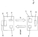
- Components of the system are a first device 12 with a first transmitter 13 and first receiver 14 as well as a second device 15 with second transmitter 16 and second receiver 17.
- the devices 12, 15 are provided and equipped for sending and receiving as well as for signal processing.
- the two devices 12, 15 are aligned with one another and are arranged adjacent but at a distance from one another, so that transmission of electromagnetic signals is possible.
- the first device 12 is assigned to a vehicle chassis, in particular held on a chassis frame.
- the second device 15 is preferably assigned to a vehicle axle and in particular held on an axle carrier. The arrangement is selected such that the first device 12 is held approximately vertically above the second device 15.
- the two devices 12, 15 With the aid of the two devices 12, 15 a height measurement takes place or a measurement of the change in the distance between the vehicle chassis and the vehicle axle.
- the two devices 12, 15 are held in the area of a rear axle 18.
- the system with the two devices 12, 15 is provided twice, namely once on the left and once on the right on the rear axle 18. Further measuring points (systems), for example on a front axle, are also possible.
- the height is measured cyclically at short intervals, preferably at intervals of 25 ms or less.
- the first transmitter 13 contains an antenna and generates a low-frequency alternating magnetic field of 125 kHz. Said antenna is oriented in the direction of the second device 15. The alternating magnetic field is aligned accordingly.
- the second receiver 17 contains a receiving antenna with an electronic circuit for determining the field strength of the low-frequency magnetic field.
- the associated capability of the circuit is called RSSI (Received Signal Strength Indication).
- RSSI is used, among other things, in wireless networks based on the IEEE 802.11 standard.
- the second device 15 can have an electrical circuit known in connection with keyless entry systems (keyless entry / go), for example the NCF 2952 or NCF 2951 from the manufacturer NXP Semiconductors N.V.
- keyless entry systems keyless entry / go
- NCF 2952 or NCF 2951 from the manufacturer NXP Semiconductors N.V.
- the messages from the second receiver 17 cyclically, e.g. Field strength determined every 20 ms correlates with the distance between the two devices 12, 15 from one another. Correspondingly, changes in the distance can be determined by changing the field strength.
- the magnitude of the field strength determined by the second receiver 17 is converted in the second device 15 into a high-frequency (or ultra-high-frequency) signal with preferably 433 or 868 MHz.
- the signal is encrypted and / or provided with a sender identifier and broadcast by the second transmitter 16.
- the first receiver 14 receives and checks (and decrypts) the broadcast signal.
- the received signal is converted into a standardized output signal.
- an interface 19 is provided in the first device 12.
- the first device 12 also has an in particular multi-pole socket 20 for connecting a connecting line 21.
- the latter is connected to the control device 11 for forwarding the output signal and thus connects the system for height measurement to the control device 11.
- the second device 15 is supplied with electrical energy via a built-in long-life battery 22.
- the first device 12 is connected via the line 21 to an on-board network (not shown) of the truck 10.
- the line 21 has at least three conductors, namely for ground, device voltage and signal.
- both are connected to the control unit 11 via lines.
- the control device can then also detect and regulate a one-sided change in height.
- a number of advantages are associated with the system described. There are no mechanical parts that can wear out. There are no inaccuracies such as those caused by bearing play and / or transverse deflection of a coupling rod. Additional connections are not required, preferably only the connection to a control unit. The material costs are low. A direct height measurement takes place, that is, the distance measurement is not dependent on a rotary movement, as is the case with a pivotable coupling rod. This means that there is no sinusoidal distortion of the measured values.
- the devices provided can be installed directly on the vehicle chassis and on the vehicle axle, at almost any point. Installation in the air springs is not required. In the event of a fault, an exchange can be carried out quickly and inexpensively.
Landscapes
- Physics & Mathematics (AREA)
- General Physics & Mathematics (AREA)
- Engineering & Computer Science (AREA)
- Mechanical Engineering (AREA)
- Vehicle Body Suspensions (AREA)
Description
- Die Erfindung betrifft ein Verfahren zur Höhenmessung in einem Fahrzeug durch Bestimmung des Abstands zwischen Fahrzeugchassis und Fahrzeugachse oder damit verbundener Teile, wobei eine erste Einrichtung mit erstem Sender und erstem Empfänger einerseits und eine zweite Einrichtung mit zweitem Sender und zweitem Empfänger andererseits zusammenwirken, wobei der erste Sender ein elektromagnetisches Feld erzeugt, der zweite Empfänger das elektromagnetische Feld detektiert, die zweite Einrichtung mit dem zweiten Sender aus dem detektierten Feld ein Signal erzeugt und sendet, welches mit dem Abstand vom ersten Sender zum zweiten Empfänger korreliert, und die erste Einrichtung mit dem ersten Empfänger das Signal empfängt. Daneben betrifft die Erfindung ein System zur Höhenmessung, eine elektronisch geregelte Luftfederung mit dem System und ein Fahrzeug mit dem System. Nutzfahrzeuge mit Luftfederung sind üblicherweise mit einer automatischen Niveauregelung ausgestattet. Ein beladenes Fahrzeug weist dadurch die gleiche Höhe auf wie ein unbeladenes Fahrzeug, d. h., der Abstand zwischen Fahrzeugchassis und Fahrzeugachse ist beim beladenen Fahrzeug nicht kleiner als beim unbeladenen Fahrzeug.
- Teil der automatischen Niveauregulierung ist häufig eine mechanische Kopplung zwischen Fahrzeugchassis und Fahrzeugachse, nämlich eine Koppelstange, die üblicherweise mit einem Wegsensor zur Erfassung der Höhendifferenz verbunden ist. Durch Bewegung der Koppelstange und Betätigung des Wegsensors werden über die zugehörige Fahrzeugelektronik Druckluftventile zum Belüften oder Entlüften der Luftfederung angesteuert. Wenn das Fahrzeug beladen wird, drückt das Fahrzeugchassis auf die Fahrzeugachse, der Abstand verringert sich, die Bewegung der Koppelstange veranlasst das Öffnen eines Belüftungsventils, so dass das Fahrzeugchassis wieder auf die ursprüngliche Höhe angehoben wird. In umgekehrter Richtung erfolgt die Niveauregulierung beim Entladen des Fahrzeugs. Die Höhenbestimmung ist durch die Kombination Koppelstange-Wegsensor und die Anbindung an die elektronisch geregelte Luftfederung mechanisch aufwendig.
- Für die Niveauregulierung maßgeblich ist die Änderung des Abstands zwischen Fahrzeugchassis und Fahrzeugachse. Gemessen werden kann dieser Abstand direkt oder über Hilfspunkte, also über mit Fahrzeugchassis und Fahrzeugachse verbundenen Teilen, etwa einem Fahrwerkrahmen als Teil des Fahrzeugchassis einerseits und Teilen der Radaufhängung, welche zur Fahrzeugachse gehört, andererseits.
- In der
WO 2005/049346 A1 sind verschiedene Ausführungen einer Niveauregelung offenbart, mit einem oder ohne ein Luftfederventil. - Aus der
DE 197 01 530 C1 ist ein Federungssystem für Lastkraftwagen mit Gasdruckfedern und Niveauregulierung bekannt. Innerhalb der Gasdruckfeder findet eine Abstandsmessung statt, durch die Übersendung eines Ultraschallsignals, die Rücksendung eines elektromagnetischen Signals und die Zeitnahme von der Aussendung des Ultraschallsignals bis zum Eingang des elektromagnetischen Signals. - Aus der
EP 1 834 190 B1 ist ein Abstandsanzeigesystem für Luftfedern bekannt, mit einer Sende-Empfangsvorrichtung auf einer Seite und einem Transponder mit Antenne auf einer anderen Seite. Mit der Antenne wird eine Rückstreumodulation ausgestrahlt, wobei sich die Modulation der Amplitude abhängig vom Abstand verändert. - In der
EP 1 857 305 A1 ist ein luftgefedertes Fahrwerk mit Niveau-Messeinrichtung offenbart, mit einer aktiven Sensoreinheit und einem passiven Element. Die aktive Sensoreinheit versorgt das passive Element über ein magnetisches Wechselfeld mit Energie, das passive Element antwortet auf eine Anfrage der aktiven Sensoreinheit und die aktive Sensoreinheit wertet die Feldstärke der Antwort des passiven Elements aus. - Die bei der Formulierung des Anspruchs 1 berücksichtigte
US 2007/0171036 A1 offenbart eine Höhenmessung in einer Luftfeder eines Fahrzeugs. Über ein erstes Sender-Empfänger-Paar wird eine elektromagnetische Welle übertragen. Daraus wird eine zweite elektromagnetische Welle erzeugt in Relation zum Abstand zwischen Sender und Empfänger. Die zweite elektromagnetische Welle wird über ein zweites Sender-Empfänger-Paar in Gegenrichtung zur ersten elektromagnetischen Welle übertragen. - In der
US 2014/0306388 A1 ist ein Verfahren zur Höhenmessung in einer Luftfeder eines Fahrzeugs offenbart. Ein oberer Sender übersendet elektromagnetische Energie an einen unteren Empfänger, welcher daraus elektrische Energie erzeugt und einem unteren Sender bereitstellt. Dieser übersendet ein elektromagnetisches Signal an einen oberen Empfänger. Letzterer ermittelt aus dem empfangenen Signal den Abstand. - Aufgabe der vorliegenden Erfindung ist die Schaffung einer einfachen und sicheren Alternative zu den vorhandenen Verfahren. Insbesondere sollen der Ersatz der mechanischen Koppelstange und die Anbindung an eine elektronisch geregelte Luftfederung einfach möglich sein.
- Das erfindungsgemäße Verfahren weist die Merkmale des Anspruchs 1 auf. Dabei ist vorgesehen, dass der erste Sender ein elektromagnetisches Feld erzeugt, dass der zweite Empfänger das elektromagnetische Feld detektiert, dass die zweite Einrichtung mit dem zweiten Sender aus dem detektierten Feld ein Signal erzeugt und sendet, welches mit dem Abstand vom ersten Sender zum zweiten Empfänger korreliert, und dass die erste Einrichtung mit dem ersten Empfänger das Signal empfängt. Die erste Einrichtung verfügt dann über ein Signal, welches den Abstand vom ersten Sender zum zweiten Empfänger repräsentiert. Das Signal kann über übliche Schnittstellen einem Steuergerät für die elektronisch geregelte Luftfederung zugeführt werden. Insbesondere ist vorgesehen, dass die zweite Einrichtung mit dem zweiten Sender nur dann ein Signal sendet, wenn vom zweiten Empfänger eine Veränderung des elektromagnetischen Feldes detektiert wurde.
- Die erste Einrichtung ist dem Fahrzeugchassis zugeordnet, die zweite Einrichtung der Fahrzeugachse (oder jeweils damit verbundenen Teilen). Möglich ist auch eine umgekehrte Anordnung mit der ersten Einrichtung an einem der Fahrzeugachse zuordneten Teil. Vorzugsweise ist die erste Einrichtung mit erstem Sender und erstem Empfänger aber am Fahrzeugchassis oder an einem Teil desselben gehalten.
- Nach einem weiteren Gedanken der Erfindung ist das vom ersten Sender erzeugte elektromagnetische Feld ein Feld mit niedriger Frequenz, vorzugsweise unter 135 kHz. Insbesondere weist das elektromagnetische Feld eine Frequenz von 125 kHz auf.
- Gemäß einem weiteren Gedanken der Erfindung ist das vom zweiten Sender gesendete Signal ein elektromagnetisches Signal im Hochfrequenzbereich oder im Ultrahochfrequenzbereich, insbesondere mit etwa 433 MHz oder 868 MHz.
- Die Verwendung unterschiedlicher Frequenzen für das Signal des ersten Senders und das Signal des zweiten Senders verringert eine gegenseitige Beeinflussung. Das elektromagnetische Feld niedriger Frequenz ist vorzugsweise direkt auf den zweiten Empfänger ausgerichtet durch Gestaltung und Anordnung einer Antenne des ersten Senders. Das elektromagnetische Signal im Hochfrequenzbereich oder im Ultrahochfrequenzbereich ist vorzugsweise verschlüsselt und nur vom ersten Empfänger lesbar. Fehlfunktionen durch eng beieinander stehende Fahrzeuge sind dadurch ausgeschlossen.
- Nach einem weiteren Gedanken der Erfindung detektiert der zweite Empfänger die Stärke des elektromagnetischen Feldes. Letzteres wird vom ersten Sender erzeugt und ausgestrahlt.
- Nach einem weiteren Gedanken der Erfindung ist vorgesehen, dass die erste Einrichtung aus dem empfangenen Signal ein standardisiertes Ausgangssignal erzeugt und bereitstellt, vorzugsweise ein PWM-Signal oder ein analoges Spannungssignal. Dieses Ausgangssignal kann von Steuergeräten für die Luftfederung für die Zwecke der Niveauregelung oder für andere mit einer Höhenmessung verbundene Zwecke verarbeitet werden.
- Vorteilhafterweise wird eine Fehlerkompensation des Signals durchgeführt, vorzugsweise vor Generierung des Ausgangssignals.
- Erfindungsgemäß ist vorgesehen, dass die zweite Einrichtung mit dem zweiten Sender nur dann ein Signal sendet, wenn vom zweiten Empfänger eine Veränderung des elektromagnetischen Feldes detektiert wurde. Dabei kann es auf die Stärke oder den zeitlichen Verlauf der Veränderung ankommen. Insbesondere ist folgender Ablauf vorgesehen:
Die zweite Einrichtung speichert einen Wert ab, der mit dem detektierten elektromagnetischen Feld korreliert. Nach Ablauf eines Zeitintervalls, zum Beispiel nach 20 ms, wird ein neuer Wert detektiert und mit dem zuvor gespeicherten (alten) Wert verglichen. Nur wenn die derart berechnete Differenz der Werte eine vorgegebene Differenz überschreitet, werden der neue Wert gespeichert und der alte Wert gelöscht. Auch erzeugt die zweite Einrichtung aus dem neuen Wert das Signal und sendet dieses. Wenn die Differenz der Werte zu klein ist, bleibt der alte Wert gespeichert und ein Signal wird nicht erzeugt oder gesendet. Durch diesen Ablauf wird die Energieversorgung der zweiten Einrichtung weniger belastet. - Nach einem weiteren Gedanken der Erfindung ist vorgesehen, dass das vom zweiten Sender gesendete Signal eine Absender-Kennung enthält. Die Kennung ermöglicht eine Unterscheidung zwischen verschiedenen Sendern, so dass Fehler durch benachbart zueinander stehende Fahrzeuge vermieden werden. Die erste Einrichtung verarbeitet nur Signale mit der "richtigen" Absender-Kennung, das heißt von der zugeordneten zweiten Einrichtung.
- Nach einem weiteren Gedanken der Erfindung ist vorgesehen, dass die zweite Einrichtung ihrerseits nur nach einer Identitätsprüfung und/oder nach einem Synchronisationsvorgang mit der zugeordneten ersten Einrichtung sendet (Listen-Before-Talk-Prinzip). Hierdurch wird die Gefahr einer gegenseitigen Beeinflussung mehrerer Einrichtungen weiter verringert.
- Das erfindungsgemäße System weist die Merkmale des Anspruchs 8 auf. Dabei ist der erste Sender zum Erzeugen eines elektromagnetischen Feldes vorgesehen und der zweite Empfänger zum Detektieren des elektromagnetischen Feldes. Die zweite Einrichtung mit dem zweiten Sender ist zum Erzeugen und Senden eines Signals vorgesehen, wobei das Signal mit dem Abstand vom ersten Sender zum zweiten Empfänger korreliert. Die erste Einrichtung mit dem ersten Empfänger ist zum Empfang des gesendeten Signals vorgesehen, vorzugsweise auch zur Weiterleitung und/oder Weiterverarbeitung des Signals. Insbesondere sendet die zweite Einrichtung mit dem zweiten Sender nur dann ein Signal, wenn vom zweiten Empfänger eine Veränderung des elektromagnetischen Feldes detektiert wurde.
- Nach einem weiteren Gedanken der Erfindung ist die erste Einrichtung dem Fahrzeugchassis zugeordnet und vorzugsweise mit einem elektrischen Netz des Fahrzeugs - einem Bordnetz - verbunden. Entsprechend ist die zweite Einrichtung vorzugsweise der Fahrzeugachse zugeordnet und insbesondere nicht mit dem Bordnetz verbunden. Die Zuordnung kann aber auch genau umgekehrt sein. Nach einem weiteren Gedanken der Erfindung weist die zweite Einrichtung eine eigene elektrische Energiequelle auf, welche vorzugsweise von einer elektrischen Energiequelle der ersten Einrichtung oder von einer Energiequelle des Fahrzeugs unabhängig ist. Die eigene elektrische Energiequelle ist insbesondere eine Langzeit-Batterie.
- Nach einem weiteren Gedanken der Erfindung ist vorgesehen, dass eine elektrische Energiequelle für vorzugsweise nur eine der beiden Einrichtungen eine Lithium-Ionen-Batterie ist, insbesondere eine Lithium-Thionylchlorid-Batterie. Vorzugsweise ist die Lithium-Ionen-Batterie als elektrische Energiequelle für die zweite Einrichtung vorgesehen.
- Nach einem weiteren Gedanken der Erfindung weist eine elektrische Energiequelle für vorzugsweise nur eine der beiden Einrichtungen eine Kapazität von 10 Ah oder weniger auf, insbesondere von etwa 2,5 Ah. Vorzugsweise beträgt die Ausgangs-Spannung der Energiequelle etwa 5,4 V oder weniger, insbesondere etwa 3,6 V.
- Nach einem weiteren Gedanken der Erfindung sind die beiden Einrichtungen außerhalb von Luftfederbälgen am Fahrzeug angebracht. Montage und Austausch der Einrichtungen sind dadurch besonders einfach.
- Verfahren und System können vorgesehen sein um eine Fahrzeugachse insgesamt zu detektieren. Dann genügt eine einfache Ausführung mit einer ersten Einrichtung und einer zweiten Einrichtung. Alternativ können beide Enden einer Fahrzeugachse detektiert werden, bzw. die Räder der Fahrzeugachse. Dann sind jedem Ende der Fahrzeugachse jeweils eine erste Einrichtung und eine zweite Einrichtung zugeordnet. Schließlich können auch mehrere Fahrzeugachsen insgesamt oder an beiden Enden detektiert werden. Es sind dann entsprechend viele erste und zweite Einrichtungen vorgesehen.
- Eine erfindungsgemäße, elektronisch geregelte Luftfederung weist die Merkmale des Anspruchs 15 auf, nämlich ein erfindungsgemäßes System. Als Luftfedern sind vorzugsweise Luftfederbälge vorgesehen.
- Nach einem weiteren Gedanken der Erfindung ist die Luftfederung mit einer manuell betätigbaren Ventilanordnung zum Heben und/oder Senken eines Fahrzeugaufbaus/Fahrzeugchassis versehen. Eine manuell betätigbare Ventilanordnung mit Hebe- und Senkventilen ist beispielsweise in der
WO 2005/049346 A1 gezeigt. - Nach einem weiteren Gedanken der Erfindung weist die Luftfederung ein Luftfederventil auf. Eine Luftfederung mit Luftfederventil ist beispielsweise in der genannten
WO 2005/049346 A1 gezeigt. - Nach einem weiteren Gedanken der Erfindung ist die Luftfederung mit einem Drucksensor zur Messung des innerhalb eines Luftfederbalgs herrschenden Drucks versehen. Hierzu reicht es aus, wenn der Drucksensor druckseitig mit den Luftfederbälgen der Luftfederung verbunden ist, wie beispielsweise in der bereits genannten
WO 2005/049346 A1 dargestellt. - Ein erfindungsgemäßes Fahrzeug weist die Merkmale des Anspruchs 19 auf. Bestandteil ist ein erfindungsgemäßes System, insbesondere eine erfindungsgemäße Luftfederung.
- Ein elektronisches Steuergerät kann für eine elektronisch geregelte Luftfederung vorgesehen : sein. Das Steuergerät selbst ist nicht Teil der Erfindung. Vorhanden ist eine Schnittstelle zum Empfang des von der ersten Einrichtung weitergeleiteten oder weiterverarbeiteten Signals und mit einer Software zur Verarbeitung des Signals. Das von der Schnittstelle empfangene Signal wird vorzugsweise als Ausgangssignal der ersten Einrichtung bezeichnet. Weitere Merkmale der Erfindung ergeben sich aus der Beschreibung im Übrigen und aus den Ansprüchen. Vorteilhafte Ausführungsformen der Erfindung werden nachfolgend anhand von Zeichnungen näher erläutert. Es zeigen:
-
Fig. 1 zwei Einrichtungen zum Senden und Empfangen von Signalen in schematischer Darstellung, -
Fig. 2 einen Lastkraftwagen (Motorwagen) mit den beiden Einrichtungen gemäßFig. 1 . - Ein Lastkraftwagen 10 ist in bekannter Weise mit einer nicht näher gezeigten Luftfederung und einem zugehörigen Steuergerät 11 ausgestattet.
- Im Zusammenhang mit der Luftfederung ist wenigstens ein System zur Höhenmessung im Lastkraftwagen 10 installiert. Bestandteile des Systems sind eine erste Einrichtung 12 mit erstem Sender 13 und erstem Empfänger 14 sowie eine zweite Einrichtung 15 mit zweitem Sender 16 und zweitem Empfänger 17. Die Einrichtungen 12, 15 sind zum Senden und Empfangen sowie zur Signalverarbeitung vorgesehen und ausgestattet.
- Die beiden Einrichtungen 12, 15 sind aufeinander ausgerichtet und benachbart aber mit Abstand zueinander angeordnet, so dass eine Übertragung elektromagnetischer Signale möglich ist. Dabei ist die erste Einrichtung 12 einem Fahrzeugchassis zugeordnet, insbesondere an einem Fahrwerkrahmen gehalten. Die zweite Einrichtung 15 ist vorzugsweise einer Fahrzeugachse zugeordnet und insbesondere an einem Achsträger gehalten. Die Anordnung ist derart gewählt, dass die erste Einrichtung 12 etwa vertikal über der zweiten Einrichtung 15 gehalten ist.
- Mit Hilfe der beiden Einrichtungen 12, 15 findet eine Höhenmessung statt bzw. eine Messung der Änderung des Abstands zwischen Fahrzeugchassis und Fahrzeugachse. Die beiden Einrichtungen 12, 15 sind im Bereich einer Hinterachse 18 gehalten. Alternativ ist das System mit den beiden Einrichtungen 12, 15 zweifach vorgesehen, nämlich einmal links und einmal rechts an der Hinterachse 18. Möglich sind noch weitere Messpunkte (Systeme), etwa an einer Vorderachse.
- Die Höhenmessung erfolgt zyklisch in kurzen Abständen, vorzugsweise in Abständen von 25 ms oder weniger.
- Der erste Sender 13 beinhaltet eine Antenne und erzeugt ein niedrigfrequentes magnetisches Wechselfeld von 125 kHz. Die genannte Antenne ist in Richtung auf die zweite Einrichtung 15 ausgerichtet. Entsprechend ist das magnetische Wechselfeld ausgerichtet.
- Der zweite Empfänger 17 beinhaltet eine Empfangsantenne mit einem elektronischen Schaltkreis zur Bestimmung der Feldstärke des niedrigfrequenten Magnetfelds. Die damit verbundene Fähigkeit des Schaltkreises wird als RSSI (Received Signal Strength Indication) bezeichnet. RSSI findet unter anderem Verwendung in drahtlosen Netzwerken nach dem Standard IEEE 802.11.
- Für die Verarbeitung der vom zweiten Empfänger 17 ermittelten Feldstärke kann die zweite Einrichtung 15 einen im Zusammenhang mit schlüssellosen Fahrzeug-Zugangssystemen (keyless entry/go) bekannten elektrischen Schaltkreis aufweisen, etwa den NCF 2952 oder NCF 2951 des Herstellers NXP Semiconductors N. V.
- Die vom zweiten Empfänger 17 zyklisch, z.B. alle 20 ms ermittelte Feldstärke korreliert mit dem Abstand der beiden Einrichtungen 12, 15 voneinander. Entsprechend sind Änderungen des Abstands über die Änderung der Feldstärke bestimmbar. Die vom zweiten Empfänger 17 ermittelte Größe der Feldstärke wird in der zweiten Einrichtung 15 umgewandelt in ein hochfrequentes (bzw. ultrahochfrequentes) Signal mit vorzugsweise 433 bzw. 868 MHz. Außerdem wird das Signal verschlüsselt und/oder mit einer Absender-Kennung versehen und vom zweiten Sender 16 ausgestrahlt.
- Der erste Empfänger 14 empfängt und prüft (und entschlüsselt) das ausgestrahlte Signal. In der ersten Einrichtung 12 wird das empfangene Signal umgewandelt in ein standardisiertes Ausgangssignal. Hierzu ist in der ersten Einrichtung 12 eine Schnittstelle 19 vorgesehen.
- Die erste Einrichtung 12 weist außerdem eine insbesondere mehrpolige Buchse 20 zum Anschluss einer Verbindungsleitung 21 auf. Letztere ist zur Weiterleitung des Ausgangssignals an das Steuergerät 11 angeschlossen und verbindet so das System zur Höhenmessung mit dem Steuergerät 11.
- Die zweite Einrichtung 15 wird über eine eingebaute Langzeit-Batterie 22 mit elektrischer Energie versorgt. Im Gegensatz dazu ist die erste Einrichtung 12 über die Leitung 21 an ein nicht gezeigtes Bordnetz des Lastkraftwagens 10 angeschlossen. Die Leitung 21 weist mindestens drei Leiter auf, nämlich für Masse, Gerätespannung und Signal.
- Bei Anordnung von zwei Systemen an der Hinterachse sind beide über Leitungen an das Steuergerät 11 angeschlossen. Das Steuergerät kann dann auch eine einseitige Höhenänderung detektieren und regeln.
- Mit dem beschriebenen System ist eine ganze Reihe von Vorteilen verknüpft. Es sind keine mechanischen Teile vorhanden, die abnutzen können. Es treten keine Ungenauigkeiten auf, wie sie durch Lagerspiel und/oder Querauslenkung einer Koppelstange hervorgerufen werden. Zusätzliche Verbindungen sind nicht erforderlich, vorzugsweise nur der Anschluss an ein Steuergerät. Die Materialkosten sind gering. Es findet eine direkte Höhenmessung statt, das heißt, die Abstandsmessung ist nicht von einer Drehbewegung abhängig, wie bei einer schwenkbaren Koppelstange. Dadurch findet keine sinusförmige Verzerrung der Messwerte statt. Die vorgesehenen Einrichtungen können direkt am Fahrzeugchassis und an der Fahrzeugachse angebaut werden, an fast beliebigen Stellen. Ein Einbau in die Luftfedern ist nicht erforderlich. Im Fehlerfall kann schnell und kostengünstig ein Austausch durchgeführt werden.
Claims (19)
- Verfahren zur Höhenmessung in einem Fahrzeug durch Bestimmung des Abstands zwischen Fahrzeugchassis und Fahrzeugachse oder damit verbundener Teile, wobei eine erste Einrichtung (12) mit erstem Sender (13) und erstem Empfänger (14) einerseits und eine zweite Einrichtung (15) mit zweitem Sender (16) und zweitem Empfänger (17) andererseits zusammenwirken,
wobei der erste Sender (13) ein elektromagnetisches Feld erzeugt,
der zweite Empfänger (17) das elektromagnetische Feld detektiert,
die zweite Einrichtung (15) mit dem zweiten Sender (16) aus dem detektierten Feld ein Signal erzeugt und sendet, welches mit dem Abstand vom ersten Sender (13) zum zweiten Empfänger (17) korreliert,
und die erste Einrichtung (12) mit dem ersten Empfänger (14) das Signal empfängt, dadurch gekennzeichnet, dass die zweite Einrichtung (15) mit dem zweiten Sender (16) nur dann ein Signal sendet, wenn vom zweiten Empfänger (17) eine Veränderung des elektromagnetischen Feldes detektiert wurde. - Verfahren nach Anspruch 1, dadurch gekennzeichnet, dass das vom ersten Sender (13) erzeugte elektromagnetische Feld ein Feld mit niedriger Frequenz ist, vorzugsweise unter 135 kHz.
- Verfahren nach Anspruch 1 oder 2, dadurch gekennzeichnet, dass das vom zweiten Sender (16) gesendete Signal ein elektromagnetisches Signal im Hochfrequenzbereich oder im Ultrahochfrequenzbereich ist, insbesondere mit etwa 433 MHz oder 868 MHz.
- Verfahren nach Anspruch 1 oder einem der weiteren Ansprüche, dadurch gekennzeichnet, dass der zweite Empfänger (17) die Stärke des elektromagnetischen Feldes detektiert.
- Verfahren nach Anspruch 1 oder einem der weiteren Ansprüche, dadurch gekennzeichnet, dass die erste Einrichtung aus dem empfangenen Signal ein standardisiertes Ausgangssignal erzeugt und bereitstellt.
- Verfahren nach Anspruch 1 oder einem der weiteren Ansprüche, dadurch gekennzeichnet, dass die zweite Einrichtung (15) mit dem zweiten Sender (16) nur dann ein Signal sendet, wenn die Veränderung des elektromagnetischen Feldes eine vorgegebene Differenz überschreitet.
- Verfahren nach Anspruch 1 oder einem der weiteren Ansprüche, dadurch gekennzeichnet, dass das vom zweiten Sender (16) gesendete Signal eine Absender-Kennung enthält.
- System zur Höhenmessung in einem Fahrzeug durch Bestimmung des Abstands zwischen Fahrzeugchassis und Fahrzeugachse oder damit verbundener Teile,
wobei eine erste Einrichtung (12) mit erstem Sender (13) und erstem Empfänger (14) einerseits und eine zweite Einrichtung (15) mit zweitem Sender (16) und zweitem Empfänger (17) andererseits zusammenwirken, insbesondere zur Durchführung des Verfahrens nach einem der voranstehenden Ansprüche,
wobei der erste Sender (13) zum Erzeugen eines elektromagnetischen Feldes vorgesehen ist,
der zweite Empfänger (17) zum Detektieren des elektromagnetischen Feldes vorgesehen ist,
die zweite Einrichtung mit dem zweiten Sender (16) zum Erzeugen und Senden eines Signals vorgesehen ist, wobei das Signal mit dem Abstand vom ersten Sender (13) zum zweiten Empfänger (17) korreliert,
und die erste Einrichtung (12) mit dem ersten Empfänger (14) zum Empfang des Signals vorgesehen ist,
dadurch gekennzeichnet, dass die zweite Einrichtung (15) mit dem zweiten Sender (16) nur dann ein Signal sendet, wenn vom zweiten Empfänger (17) eine Veränderung des elektromagnetischen Feldes detektiert wurde. - System nach Anspruch 8, dadurch gekennzeichnet, dass die erste Einrichtung (12) dem Fahrzeugchassis zugeordnet ist und vorzugsweise mit einem elektrischen Netz des Fahrzeugs - einem Bordnetz - verbunden ist.
- System nach Anspruch 8 oder 9, dadurch gekennzeichnet, dass die zweite Einrichtung (15) eine eigene elektrische Energiequelle aufweist, welche vorzugsweise von einer elektrischen Energiequelle der ersten Einrichtung oder von einer Energiequelle des Fahrzeugs unabhängig ist.
- System nach einem der Ansprüche 8 - 10, dadurch gekennzeichnet, dass eine elektrische Energiequelle für vorzugsweise nur eine der beiden Einrichtungen (12, 15) eine Lithium-Ionen-Batterie ist, insbesondere eine Lithium-Thionylchlorid-Batterie.
- System nach einem der Ansprüche 8 - 11, dadurch gekennzeichnet, dass eine elektrische Energiequelle für vorzugsweise nur eine der beiden Einrichtungen (12, 15) eine Kapazität kleiner oder gleich 10 Ah aufweist.
- System nach einem der Ansprüche 8 - 12, dadurch gekennzeichnet, dass eine elektrische Energiequelle für vorzugsweise nur eine der beiden Einrichtungen (12, 15) eine Ausgangs-Spannung von etwa 5,4 V oder weniger, insbesondere etwa 3,6 V aufweist.
- System nach einem der Ansprüche 8 - 13, dadurch gekennzeichnet, dass die beiden Einrichtungen (12, 15) außerhalb von Luftfederbälgen am Fahrzeug angebracht sind.
- Elektronisch geregelte Luftfederung für ein Fahrzeug, mit einem System nach einem der Ansprüche 8 - 14.
- Luftfederung nach Anspruch 15, gekennzeichnet durch eine manuell betätigbare Ventilanordnung zum Heben und/oder Senken eines Fahrzeugaufbaus/Fahrzeugchassis.
- Luftfederung nach Anspruch 15 oder 16, gekennzeichnet durch ein Luftfederventil.
- Luftfederung nach einem der Ansprüche 15 bis 17, gekennzeichnet durch einen Drucksensor zur Messung des innerhalb eines Luftfederbalgs herrschenden Drucks.
- Fahrzeug mit einem System nach einem der Ansprüche 8 - 14, insbesondere mit einer Luftfederung nach einem der Ansprüche 15 bis 18.
Applications Claiming Priority (2)
| Application Number | Priority Date | Filing Date | Title |
|---|---|---|---|
| DE102015002167.2A DE102015002167A1 (de) | 2015-02-24 | 2015-02-24 | Verfahren und System zur Höhenmessung in einem Fahrzeug |
| PCT/EP2016/000207 WO2016134823A1 (de) | 2015-02-24 | 2016-02-06 | Verfahren und system zur höhenmessung in einem fahrzeug |
Publications (2)
| Publication Number | Publication Date |
|---|---|
| EP3261864A1 EP3261864A1 (de) | 2018-01-03 |
| EP3261864B1 true EP3261864B1 (de) | 2020-12-16 |
Family
ID=55315383
Family Applications (1)
| Application Number | Title | Priority Date | Filing Date |
|---|---|---|---|
| EP16703435.4A Active EP3261864B1 (de) | 2015-02-24 | 2016-02-06 | Verfahren und system zur höhenmessung in einem fahrzeug |
Country Status (4)
| Country | Link |
|---|---|
| US (1) | US20180111438A1 (de) |
| EP (1) | EP3261864B1 (de) |
| DE (1) | DE102015002167A1 (de) |
| WO (1) | WO2016134823A1 (de) |
Families Citing this family (2)
| Publication number | Priority date | Publication date | Assignee | Title |
|---|---|---|---|---|
| GB202202512D0 (en) * | 2022-02-23 | 2022-04-06 | Don Bur Bodies & Trailers Ltd | Suspension monitoring system |
| DE102023106891A1 (de) | 2023-03-20 | 2024-09-26 | Zf Cv Systems Europe Bv | Elektronische Steuereinheit einer Niveauregulierungseinrichtung eines Fahrzeugs so-wie Verfahren zur Achslastermittlung mit einer solchen Steuereinheit |
Family Cites Families (9)
| Publication number | Priority date | Publication date | Assignee | Title |
|---|---|---|---|---|
| SE456118B (sv) * | 1985-12-12 | 1988-09-05 | Stiftelsen Inst Mikrovags | Forfarande och anordning for att meta avstand mellan ett forsta och ett andra foremal med signaler av mikrovagsfrekvens |
| DE19701530C1 (de) | 1997-01-17 | 1998-08-06 | Contitech Luftfedersyst Gmbh | Einrichtung zur Bestimmung des axialen Abstandes zweier Endglieder einer Gasdruckfeder |
| DE10354056B4 (de) | 2003-11-19 | 2015-08-20 | Wabco Gmbh | Ventileinrichtung für eine Luftfederungseinrichtung für ein Fahrzeug |
| US7490817B2 (en) | 2005-01-04 | 2009-02-17 | Bfs Diversified Products Llc | Distance indicating system and method |
| US7420462B2 (en) * | 2006-01-23 | 2008-09-02 | Bfs Diversified Products, Llc | Air spring distance indicating system and method |
| DE102006022934A1 (de) | 2006-05-15 | 2007-11-22 | Bpw Bergische Achsen Kg | Luftgefedertes Fahrwerk |
| EP2735760B1 (de) * | 2012-11-26 | 2018-06-13 | ContiTech USA, Inc. | Luftfeder mit einem Höhensensor |
| US9694640B2 (en) * | 2013-04-15 | 2017-07-04 | Stemco Kaiser Incorporated | Non-contact power supply for height sensor with single cable |
| DE102013217958A1 (de) * | 2013-09-09 | 2015-03-12 | Brehmer Gmbh & Co. Kg | Aktiver RFID-Fahrhöhensensor für luftgefederte Fahrwerksysteme |
-
2015
- 2015-02-24 DE DE102015002167.2A patent/DE102015002167A1/de not_active Withdrawn
-
2016
- 2016-02-06 US US15/553,371 patent/US20180111438A1/en not_active Abandoned
- 2016-02-06 EP EP16703435.4A patent/EP3261864B1/de active Active
- 2016-02-06 WO PCT/EP2016/000207 patent/WO2016134823A1/de not_active Ceased
Non-Patent Citations (1)
| Title |
|---|
| None * |
Also Published As
| Publication number | Publication date |
|---|---|
| EP3261864A1 (de) | 2018-01-03 |
| US20180111438A1 (en) | 2018-04-26 |
| DE102015002167A1 (de) | 2016-08-25 |
| WO2016134823A1 (de) | 2016-09-01 |
Similar Documents
| Publication | Publication Date | Title |
|---|---|---|
| DE102007007135B4 (de) | Verfahren für ein Reifenkontrollsystem | |
| DE102006018363B4 (de) | Reifenort-Detektorvorrichtung, die mit Drehrichtungs-Detektorvorrichtungen und einer Triggervorrichtung konfiguriert ist | |
| DE102007046495B4 (de) | Vorrichtung und Verfahren zur Unterscheidung der Reifen eines Doppelreifensystems | |
| DE102008032627B4 (de) | Vorrichtung zum Detektieren der Positionen von Rädern eines Fahrzeugs und Vorrichtung zum Detektieren des Reifendrucks unter Verwendung derselben | |
| DE102011050636A1 (de) | Verfahren zum Zuordnen von Kennungen von Radelektroniken eines Reifendrucküberwachungssystems eines Fahrzeugs zu den Positionen der Räder an dem Fahrzeug | |
| DE102009053868B4 (de) | Arbeitsfahrzeug mit Steuergerät und Sensor/Aktor mit zwei redundanten Übertragungsstrecken | |
| DE102004001250B4 (de) | Vorrichtung und Verfahren zur Ermittlung der Seitenposition von Rädern | |
| DE102007014693A1 (de) | Fahrzeughöhenermittlungssystem | |
| EP3072716A1 (de) | Luftfederbalgeinheit | |
| WO2015055424A1 (de) | Verfahren und anordnung zum lokalisieren der verbauposition von rädern in einem kraftfahrzeug | |
| EP1525106B1 (de) | Einrichtung zum überwachen und drahtlosen signalisieren eines drucks oder einer druckänderung in luftreifen | |
| DE102019112481A1 (de) | Reifendrucküberwachungssystem für Lang-Lkw und Werkzeug zum Einstellen eines Reifendruckdetektors | |
| DE10342297A1 (de) | Verfahren und Einrichtung zur Ermittlung der Radposition | |
| EP3206923A1 (de) | Elektronisches bremssystem für ein fahrzeug | |
| DE102018210072B4 (de) | Verfahren zum Kalibrieren eines funkbasierten schlüssellosen Zugangssystems eines Kraftfahrzeugs, Zugangssystem und Kraftfahrzeug | |
| EP1857305B1 (de) | Luftgefedertes Fahrwerk mit Niveau-Meßeinrichtung bestehend aus Sensoreinheit und Transponder | |
| DE19701530C1 (de) | Einrichtung zur Bestimmung des axialen Abstandes zweier Endglieder einer Gasdruckfeder | |
| EP2072290B1 (de) | Reifendruckregelanlage sowie Drehdurchführung dafür | |
| DE102005059009A1 (de) | Reifendrucküberwachungssystem | |
| EP1417106A1 (de) | Verfahren und vorrichtung zum betreiben einer einrichtung zum überwachen und drahtlosen signalisieren einer druckänderung und zur automatischen druckregelung in luftreifen an fahrzeugen | |
| WO2016134823A1 (de) | Verfahren und system zur höhenmessung in einem fahrzeug | |
| EP3589914A1 (de) | Steuergerät für ein fahrzeug sowie fahrzeug mit einem derartigen steuergerät | |
| DE102021110591A1 (de) | System, Vorrichtung und Verfahren für einen Fernantennenkompensator | |
| DE102020130622B4 (de) | Messgerät zur Prozessautomatisierung im industriellen Umfeld | |
| WO2008095959A1 (de) | Verfahren und vorrichtung zum lokalisieren von an einem fahrzeug montierten reifen |
Legal Events
| Date | Code | Title | Description |
|---|---|---|---|
| STAA | Information on the status of an ep patent application or granted ep patent |
Free format text: STATUS: THE INTERNATIONAL PUBLICATION HAS BEEN MADE |
|
| PUAI | Public reference made under article 153(3) epc to a published international application that has entered the european phase |
Free format text: ORIGINAL CODE: 0009012 |
|
| STAA | Information on the status of an ep patent application or granted ep patent |
Free format text: STATUS: REQUEST FOR EXAMINATION WAS MADE |
|
| 17P | Request for examination filed |
Effective date: 20170925 |
|
| AK | Designated contracting states |
Kind code of ref document: A1 Designated state(s): AL AT BE BG CH CY CZ DE DK EE ES FI FR GB GR HR HU IE IS IT LI LT LU LV MC MK MT NL NO PL PT RO RS SE SI SK SM TR |
|
| AX | Request for extension of the european patent |
Extension state: BA ME |
|
| DAV | Request for validation of the european patent (deleted) | ||
| DAX | Request for extension of the european patent (deleted) | ||
| STAA | Information on the status of an ep patent application or granted ep patent |
Free format text: STATUS: EXAMINATION IS IN PROGRESS |
|
| 17Q | First examination report despatched |
Effective date: 20200414 |
|
| RIC1 | Information provided on ipc code assigned before grant |
Ipc: G01B 7/02 20060101ALI20200707BHEP Ipc: G01B 7/06 20060101ALI20200707BHEP Ipc: G01B 7/315 20060101ALI20200707BHEP Ipc: G01B 7/14 20060101ALI20200707BHEP Ipc: F16F 9/05 20060101ALI20200707BHEP Ipc: B60G 17/019 20060101AFI20200707BHEP |
|
| GRAP | Despatch of communication of intention to grant a patent |
Free format text: ORIGINAL CODE: EPIDOSNIGR1 |
|
| STAA | Information on the status of an ep patent application or granted ep patent |
Free format text: STATUS: GRANT OF PATENT IS INTENDED |
|
| INTG | Intention to grant announced |
Effective date: 20200818 |
|
| GRAS | Grant fee paid |
Free format text: ORIGINAL CODE: EPIDOSNIGR3 |
|
| GRAA | (expected) grant |
Free format text: ORIGINAL CODE: 0009210 |
|
| STAA | Information on the status of an ep patent application or granted ep patent |
Free format text: STATUS: THE PATENT HAS BEEN GRANTED |
|
| AK | Designated contracting states |
Kind code of ref document: B1 Designated state(s): AL AT BE BG CH CY CZ DE DK EE ES FI FR GB GR HR HU IE IS IT LI LT LU LV MC MK MT NL NO PL PT RO RS SE SI SK SM TR |
|
| REG | Reference to a national code |
Ref country code: GB Ref legal event code: FG4D Free format text: NOT ENGLISH |
|
| REG | Reference to a national code |
Ref country code: IE Ref legal event code: FG4D Free format text: LANGUAGE OF EP DOCUMENT: GERMAN |
|
| REG | Reference to a national code |
Ref country code: DE Ref legal event code: R096 Ref document number: 502016011974 Country of ref document: DE |
|
| REG | Reference to a national code |
Ref country code: AT Ref legal event code: REF Ref document number: 1345267 Country of ref document: AT Kind code of ref document: T Effective date: 20210115 |
|
| REG | Reference to a national code |
Ref country code: DE Ref legal event code: R081 Ref document number: 502016011974 Country of ref document: DE Owner name: ZF CV SYSTEMS EUROPE BV, BE Free format text: FORMER OWNER: WABCO GMBH, 30453 HANNOVER, DE Ref country code: DE Ref legal event code: R081 Ref document number: 502016011974 Country of ref document: DE Owner name: ZF CV SYSTEMS HANNOVER GMBH, DE Free format text: FORMER OWNER: WABCO GMBH, 30453 HANNOVER, DE |
|
| PG25 | Lapsed in a contracting state [announced via postgrant information from national office to epo] |
Ref country code: NO Free format text: LAPSE BECAUSE OF FAILURE TO SUBMIT A TRANSLATION OF THE DESCRIPTION OR TO PAY THE FEE WITHIN THE PRESCRIBED TIME-LIMIT Effective date: 20210316 Ref country code: RS Free format text: LAPSE BECAUSE OF FAILURE TO SUBMIT A TRANSLATION OF THE DESCRIPTION OR TO PAY THE FEE WITHIN THE PRESCRIBED TIME-LIMIT Effective date: 20201216 Ref country code: GR Free format text: LAPSE BECAUSE OF FAILURE TO SUBMIT A TRANSLATION OF THE DESCRIPTION OR TO PAY THE FEE WITHIN THE PRESCRIBED TIME-LIMIT Effective date: 20210317 Ref country code: FI Free format text: LAPSE BECAUSE OF FAILURE TO SUBMIT A TRANSLATION OF THE DESCRIPTION OR TO PAY THE FEE WITHIN THE PRESCRIBED TIME-LIMIT Effective date: 20201216 |
|
| REG | Reference to a national code |
Ref country code: NL Ref legal event code: MP Effective date: 20201216 |
|
| RAP4 | Party data changed (patent owner data changed or rights of a patent transferred) |
Owner name: ZF CV SYSTEMS HANNOVER GMBH |
|
| PG25 | Lapsed in a contracting state [announced via postgrant information from national office to epo] |
Ref country code: BG Free format text: LAPSE BECAUSE OF FAILURE TO SUBMIT A TRANSLATION OF THE DESCRIPTION OR TO PAY THE FEE WITHIN THE PRESCRIBED TIME-LIMIT Effective date: 20210316 Ref country code: LV Free format text: LAPSE BECAUSE OF FAILURE TO SUBMIT A TRANSLATION OF THE DESCRIPTION OR TO PAY THE FEE WITHIN THE PRESCRIBED TIME-LIMIT Effective date: 20201216 Ref country code: SE Free format text: LAPSE BECAUSE OF FAILURE TO SUBMIT A TRANSLATION OF THE DESCRIPTION OR TO PAY THE FEE WITHIN THE PRESCRIBED TIME-LIMIT Effective date: 20201216 |
|
| PG25 | Lapsed in a contracting state [announced via postgrant information from national office to epo] |
Ref country code: NL Free format text: LAPSE BECAUSE OF FAILURE TO SUBMIT A TRANSLATION OF THE DESCRIPTION OR TO PAY THE FEE WITHIN THE PRESCRIBED TIME-LIMIT Effective date: 20201216 Ref country code: HR Free format text: LAPSE BECAUSE OF FAILURE TO SUBMIT A TRANSLATION OF THE DESCRIPTION OR TO PAY THE FEE WITHIN THE PRESCRIBED TIME-LIMIT Effective date: 20201216 |
|
| REG | Reference to a national code |
Ref country code: LT Ref legal event code: MG9D |
|
| PG25 | Lapsed in a contracting state [announced via postgrant information from national office to epo] |
Ref country code: SK Free format text: LAPSE BECAUSE OF FAILURE TO SUBMIT A TRANSLATION OF THE DESCRIPTION OR TO PAY THE FEE WITHIN THE PRESCRIBED TIME-LIMIT Effective date: 20201216 Ref country code: PT Free format text: LAPSE BECAUSE OF FAILURE TO SUBMIT A TRANSLATION OF THE DESCRIPTION OR TO PAY THE FEE WITHIN THE PRESCRIBED TIME-LIMIT Effective date: 20210416 Ref country code: RO Free format text: LAPSE BECAUSE OF FAILURE TO SUBMIT A TRANSLATION OF THE DESCRIPTION OR TO PAY THE FEE WITHIN THE PRESCRIBED TIME-LIMIT Effective date: 20201216 Ref country code: EE Free format text: LAPSE BECAUSE OF FAILURE TO SUBMIT A TRANSLATION OF THE DESCRIPTION OR TO PAY THE FEE WITHIN THE PRESCRIBED TIME-LIMIT Effective date: 20201216 Ref country code: CZ Free format text: LAPSE BECAUSE OF FAILURE TO SUBMIT A TRANSLATION OF THE DESCRIPTION OR TO PAY THE FEE WITHIN THE PRESCRIBED TIME-LIMIT Effective date: 20201216 Ref country code: SM Free format text: LAPSE BECAUSE OF FAILURE TO SUBMIT A TRANSLATION OF THE DESCRIPTION OR TO PAY THE FEE WITHIN THE PRESCRIBED TIME-LIMIT Effective date: 20201216 Ref country code: LT Free format text: LAPSE BECAUSE OF FAILURE TO SUBMIT A TRANSLATION OF THE DESCRIPTION OR TO PAY THE FEE WITHIN THE PRESCRIBED TIME-LIMIT Effective date: 20201216 |
|
| PG25 | Lapsed in a contracting state [announced via postgrant information from national office to epo] |
Ref country code: PL Free format text: LAPSE BECAUSE OF FAILURE TO SUBMIT A TRANSLATION OF THE DESCRIPTION OR TO PAY THE FEE WITHIN THE PRESCRIBED TIME-LIMIT Effective date: 20201216 |
|
| REG | Reference to a national code |
Ref country code: DE Ref legal event code: R097 Ref document number: 502016011974 Country of ref document: DE |
|
| PG25 | Lapsed in a contracting state [announced via postgrant information from national office to epo] |
Ref country code: IS Free format text: LAPSE BECAUSE OF FAILURE TO SUBMIT A TRANSLATION OF THE DESCRIPTION OR TO PAY THE FEE WITHIN THE PRESCRIBED TIME-LIMIT Effective date: 20210416 Ref country code: MC Free format text: LAPSE BECAUSE OF FAILURE TO SUBMIT A TRANSLATION OF THE DESCRIPTION OR TO PAY THE FEE WITHIN THE PRESCRIBED TIME-LIMIT Effective date: 20201216 |
|
| PLBE | No opposition filed within time limit |
Free format text: ORIGINAL CODE: 0009261 |
|
| STAA | Information on the status of an ep patent application or granted ep patent |
Free format text: STATUS: NO OPPOSITION FILED WITHIN TIME LIMIT |
|
| REG | Reference to a national code |
Ref country code: BE Ref legal event code: MM Effective date: 20210228 |
|
| PG25 | Lapsed in a contracting state [announced via postgrant information from national office to epo] |
Ref country code: IT Free format text: LAPSE BECAUSE OF FAILURE TO SUBMIT A TRANSLATION OF THE DESCRIPTION OR TO PAY THE FEE WITHIN THE PRESCRIBED TIME-LIMIT Effective date: 20201216 Ref country code: AL Free format text: LAPSE BECAUSE OF FAILURE TO SUBMIT A TRANSLATION OF THE DESCRIPTION OR TO PAY THE FEE WITHIN THE PRESCRIBED TIME-LIMIT Effective date: 20201216 Ref country code: CH Free format text: LAPSE BECAUSE OF NON-PAYMENT OF DUE FEES Effective date: 20210228 Ref country code: LI Free format text: LAPSE BECAUSE OF NON-PAYMENT OF DUE FEES Effective date: 20210228 Ref country code: LU Free format text: LAPSE BECAUSE OF NON-PAYMENT OF DUE FEES Effective date: 20210206 |
|
| 26N | No opposition filed |
Effective date: 20210917 |
|
| PG25 | Lapsed in a contracting state [announced via postgrant information from national office to epo] |
Ref country code: DK Free format text: LAPSE BECAUSE OF FAILURE TO SUBMIT A TRANSLATION OF THE DESCRIPTION OR TO PAY THE FEE WITHIN THE PRESCRIBED TIME-LIMIT Effective date: 20201216 |
|
| PG25 | Lapsed in a contracting state [announced via postgrant information from national office to epo] |
Ref country code: ES Free format text: LAPSE BECAUSE OF FAILURE TO SUBMIT A TRANSLATION OF THE DESCRIPTION OR TO PAY THE FEE WITHIN THE PRESCRIBED TIME-LIMIT Effective date: 20201216 Ref country code: IE Free format text: LAPSE BECAUSE OF NON-PAYMENT OF DUE FEES Effective date: 20210206 |
|
| PG25 | Lapsed in a contracting state [announced via postgrant information from national office to epo] |
Ref country code: SI Free format text: LAPSE BECAUSE OF FAILURE TO SUBMIT A TRANSLATION OF THE DESCRIPTION OR TO PAY THE FEE WITHIN THE PRESCRIBED TIME-LIMIT Effective date: 20201216 |
|
| REG | Reference to a national code |
Ref country code: DE Ref legal event code: R081 Ref document number: 502016011974 Country of ref document: DE Owner name: ZF CV SYSTEMS EUROPE BV, BE Free format text: FORMER OWNER: ZF CV SYSTEMS HANNOVER GMBH, 30453 HANNOVER, DE |
|
| REG | Reference to a national code |
Ref country code: AT Ref legal event code: MM01 Ref document number: 1345267 Country of ref document: AT Kind code of ref document: T Effective date: 20210206 |
|
| PG25 | Lapsed in a contracting state [announced via postgrant information from national office to epo] |
Ref country code: AT Free format text: LAPSE BECAUSE OF NON-PAYMENT OF DUE FEES Effective date: 20210206 |
|
| PG25 | Lapsed in a contracting state [announced via postgrant information from national office to epo] |
Ref country code: IS Free format text: LAPSE BECAUSE OF FAILURE TO SUBMIT A TRANSLATION OF THE DESCRIPTION OR TO PAY THE FEE WITHIN THE PRESCRIBED TIME-LIMIT Effective date: 20210416 |
|
| PG25 | Lapsed in a contracting state [announced via postgrant information from national office to epo] |
Ref country code: BE Free format text: LAPSE BECAUSE OF NON-PAYMENT OF DUE FEES Effective date: 20210228 |
|
| PG25 | Lapsed in a contracting state [announced via postgrant information from national office to epo] |
Ref country code: CY Free format text: LAPSE BECAUSE OF FAILURE TO SUBMIT A TRANSLATION OF THE DESCRIPTION OR TO PAY THE FEE WITHIN THE PRESCRIBED TIME-LIMIT Effective date: 20201216 |
|
| P01 | Opt-out of the competence of the unified patent court (upc) registered |
Effective date: 20230528 |
|
| PG25 | Lapsed in a contracting state [announced via postgrant information from national office to epo] |
Ref country code: HU Free format text: LAPSE BECAUSE OF FAILURE TO SUBMIT A TRANSLATION OF THE DESCRIPTION OR TO PAY THE FEE WITHIN THE PRESCRIBED TIME-LIMIT; INVALID AB INITIO Effective date: 20160206 |
|
| PGFP | Annual fee paid to national office [announced via postgrant information from national office to epo] |
Ref country code: GB Payment date: 20231214 Year of fee payment: 9 |
|
| PGFP | Annual fee paid to national office [announced via postgrant information from national office to epo] |
Ref country code: FR Payment date: 20231212 Year of fee payment: 9 |
|
| PG25 | Lapsed in a contracting state [announced via postgrant information from national office to epo] |
Ref country code: MK Free format text: LAPSE BECAUSE OF FAILURE TO SUBMIT A TRANSLATION OF THE DESCRIPTION OR TO PAY THE FEE WITHIN THE PRESCRIBED TIME-LIMIT Effective date: 20201216 |
|
| PG25 | Lapsed in a contracting state [announced via postgrant information from national office to epo] |
Ref country code: MT Free format text: LAPSE BECAUSE OF FAILURE TO SUBMIT A TRANSLATION OF THE DESCRIPTION OR TO PAY THE FEE WITHIN THE PRESCRIBED TIME-LIMIT Effective date: 20201216 |
|
| PGFP | Annual fee paid to national office [announced via postgrant information from national office to epo] |
Ref country code: DE Payment date: 20241210 Year of fee payment: 10 |
|
| GBPC | Gb: european patent ceased through non-payment of renewal fee |
Effective date: 20250206 |
|
| PG25 | Lapsed in a contracting state [announced via postgrant information from national office to epo] |
Ref country code: TR Free format text: LAPSE BECAUSE OF FAILURE TO SUBMIT A TRANSLATION OF THE DESCRIPTION OR TO PAY THE FEE WITHIN THE PRESCRIBED TIME-LIMIT Effective date: 20201216 |
|
| PG25 | Lapsed in a contracting state [announced via postgrant information from national office to epo] |
Ref country code: GB Free format text: LAPSE BECAUSE OF NON-PAYMENT OF DUE FEES Effective date: 20250206 |
|
| PG25 | Lapsed in a contracting state [announced via postgrant information from national office to epo] |
Ref country code: FR Free format text: LAPSE BECAUSE OF NON-PAYMENT OF DUE FEES Effective date: 20250228 |