EP3261162A1 - Method for manufacturing curved electrode assembly - Google Patents
Method for manufacturing curved electrode assembly Download PDFInfo
- Publication number
- EP3261162A1 EP3261162A1 EP16814683.5A EP16814683A EP3261162A1 EP 3261162 A1 EP3261162 A1 EP 3261162A1 EP 16814683 A EP16814683 A EP 16814683A EP 3261162 A1 EP3261162 A1 EP 3261162A1
- Authority
- EP
- European Patent Office
- Prior art keywords
- curvature radius
- electrode assembly
- curved
- manufacturing
- present disclosure
- Prior art date
- Legal status (The legal status is an assumption and is not a legal conclusion. Google has not performed a legal analysis and makes no representation as to the accuracy of the status listed.)
- Granted
Links
Images


Classifications
-
- H—ELECTRICITY
- H01—ELECTRIC ELEMENTS
- H01M—PROCESSES OR MEANS, e.g. BATTERIES, FOR THE DIRECT CONVERSION OF CHEMICAL ENERGY INTO ELECTRICAL ENERGY
- H01M4/00—Electrodes
- H01M4/02—Electrodes composed of, or comprising, active material
- H01M4/04—Processes of manufacture in general
- H01M4/043—Processes of manufacture in general involving compressing or compaction
- H01M4/0435—Rolling or calendering
-
- H—ELECTRICITY
- H01—ELECTRIC ELEMENTS
- H01M—PROCESSES OR MEANS, e.g. BATTERIES, FOR THE DIRECT CONVERSION OF CHEMICAL ENERGY INTO ELECTRICAL ENERGY
- H01M10/00—Secondary cells; Manufacture thereof
- H01M10/04—Construction or manufacture in general
- H01M10/0468—Compression means for stacks of electrodes and separators
-
- B—PERFORMING OPERATIONS; TRANSPORTING
- B32—LAYERED PRODUCTS
- B32B—LAYERED PRODUCTS, i.e. PRODUCTS BUILT-UP OF STRATA OF FLAT OR NON-FLAT, e.g. CELLULAR OR HONEYCOMB, FORM
- B32B37/00—Methods or apparatus for laminating, e.g. by curing or by ultrasonic bonding
- B32B37/0046—Methods or apparatus for laminating, e.g. by curing or by ultrasonic bonding characterised by constructional aspects of the apparatus
- B32B37/0053—Constructional details of laminating machines comprising rollers; Constructional features of the rollers
-
- B—PERFORMING OPERATIONS; TRANSPORTING
- B32—LAYERED PRODUCTS
- B32B—LAYERED PRODUCTS, i.e. PRODUCTS BUILT-UP OF STRATA OF FLAT OR NON-FLAT, e.g. CELLULAR OR HONEYCOMB, FORM
- B32B37/00—Methods or apparatus for laminating, e.g. by curing or by ultrasonic bonding
- B32B37/06—Methods or apparatus for laminating, e.g. by curing or by ultrasonic bonding characterised by the heating method
-
- B—PERFORMING OPERATIONS; TRANSPORTING
- B32—LAYERED PRODUCTS
- B32B—LAYERED PRODUCTS, i.e. PRODUCTS BUILT-UP OF STRATA OF FLAT OR NON-FLAT, e.g. CELLULAR OR HONEYCOMB, FORM
- B32B37/00—Methods or apparatus for laminating, e.g. by curing or by ultrasonic bonding
- B32B37/10—Methods or apparatus for laminating, e.g. by curing or by ultrasonic bonding characterised by the pressing technique, e.g. using action of vacuum or fluid pressure
-
- H—ELECTRICITY
- H01—ELECTRIC ELEMENTS
- H01M—PROCESSES OR MEANS, e.g. BATTERIES, FOR THE DIRECT CONVERSION OF CHEMICAL ENERGY INTO ELECTRICAL ENERGY
- H01M10/00—Secondary cells; Manufacture thereof
- H01M10/04—Construction or manufacture in general
- H01M10/0436—Small-sized flat cells or batteries for portable equipment
-
- H—ELECTRICITY
- H01—ELECTRIC ELEMENTS
- H01M—PROCESSES OR MEANS, e.g. BATTERIES, FOR THE DIRECT CONVERSION OF CHEMICAL ENERGY INTO ELECTRICAL ENERGY
- H01M10/00—Secondary cells; Manufacture thereof
- H01M10/05—Accumulators with non-aqueous electrolyte
- H01M10/058—Construction or manufacture
- H01M10/0585—Construction or manufacture of accumulators having only flat construction elements, i.e. flat positive electrodes, flat negative electrodes and flat separators
-
- H—ELECTRICITY
- H01—ELECTRIC ELEMENTS
- H01M—PROCESSES OR MEANS, e.g. BATTERIES, FOR THE DIRECT CONVERSION OF CHEMICAL ENERGY INTO ELECTRICAL ENERGY
- H01M4/00—Electrodes
- H01M4/02—Electrodes composed of, or comprising, active material
- H01M4/04—Processes of manufacture in general
-
- H—ELECTRICITY
- H01—ELECTRIC ELEMENTS
- H01M—PROCESSES OR MEANS, e.g. BATTERIES, FOR THE DIRECT CONVERSION OF CHEMICAL ENERGY INTO ELECTRICAL ENERGY
- H01M4/00—Electrodes
- H01M4/02—Electrodes composed of, or comprising, active material
- H01M4/04—Processes of manufacture in general
- H01M4/0471—Processes of manufacture in general involving thermal treatment, e.g. firing, sintering, backing particulate active material, thermal decomposition, pyrolysis
-
- B—PERFORMING OPERATIONS; TRANSPORTING
- B32—LAYERED PRODUCTS
- B32B—LAYERED PRODUCTS, i.e. PRODUCTS BUILT-UP OF STRATA OF FLAT OR NON-FLAT, e.g. CELLULAR OR HONEYCOMB, FORM
- B32B2457/00—Electrical equipment
- B32B2457/10—Batteries
-
- H—ELECTRICITY
- H01—ELECTRIC ELEMENTS
- H01M—PROCESSES OR MEANS, e.g. BATTERIES, FOR THE DIRECT CONVERSION OF CHEMICAL ENERGY INTO ELECTRICAL ENERGY
- H01M2220/00—Batteries for particular applications
- H01M2220/30—Batteries in portable systems, e.g. mobile phone, laptop
-
- Y—GENERAL TAGGING OF NEW TECHNOLOGICAL DEVELOPMENTS; GENERAL TAGGING OF CROSS-SECTIONAL TECHNOLOGIES SPANNING OVER SEVERAL SECTIONS OF THE IPC; TECHNICAL SUBJECTS COVERED BY FORMER USPC CROSS-REFERENCE ART COLLECTIONS [XRACs] AND DIGESTS
- Y02—TECHNOLOGIES OR APPLICATIONS FOR MITIGATION OR ADAPTATION AGAINST CLIMATE CHANGE
- Y02E—REDUCTION OF GREENHOUSE GAS [GHG] EMISSIONS, RELATED TO ENERGY GENERATION, TRANSMISSION OR DISTRIBUTION
- Y02E60/00—Enabling technologies; Technologies with a potential or indirect contribution to GHG emissions mitigation
- Y02E60/10—Energy storage using batteries
-
- Y—GENERAL TAGGING OF NEW TECHNOLOGICAL DEVELOPMENTS; GENERAL TAGGING OF CROSS-SECTIONAL TECHNOLOGIES SPANNING OVER SEVERAL SECTIONS OF THE IPC; TECHNICAL SUBJECTS COVERED BY FORMER USPC CROSS-REFERENCE ART COLLECTIONS [XRACs] AND DIGESTS
- Y02—TECHNOLOGIES OR APPLICATIONS FOR MITIGATION OR ADAPTATION AGAINST CLIMATE CHANGE
- Y02P—CLIMATE CHANGE MITIGATION TECHNOLOGIES IN THE PRODUCTION OR PROCESSING OF GOODS
- Y02P70/00—Climate change mitigation technologies in the production process for final industrial or consumer products
- Y02P70/50—Manufacturing or production processes characterised by the final manufactured product
Definitions
- the present application claims priority to Korean Patent Application No. 10-2015-0089126 filed in the Republic of Korea on June 23, 2015, the disclosure of which is incorporated herein by reference.
- the present disclosure relates to a method for manufacturing an electrode assembly for an electrochemical device. More particularly, the present disclosure relates to a method for manufacturing a curved electrode assembly having a curve with a uniform curvature radius.
- Secondary batteries in typical shape include, for example, prismatic or pouch-type lithium ion secondary batteries with a small thickness for use in electronic devices such as mobile phones.
- prismatic or pouch-type secondary batteries which are in flat shape fail to efficiently use an internal space, and cannot be adapted for secondary battery applications in various shapes and sizes. Therefore, there is the demand for battery cells and battery packs having a shape that efficiently uses an internal space and has high capacity for applications of electronic devices such as mobile phones in streamlined shape and/or size.
- Conventional methods for fabricating a curved battery include a method by which a flat plate-shaped electrode assembly or battery is produced and pressed by a curved jig to fabricate a curved battery.
- US Patent Publication No. 2007/0059595 discloses a battery in which a jelly-roll type electrode assembly has a curved cross section perpendicular to a winding axis. According to the technology, it is disclosed that the curved shape is achieved through thermal compression molding using a concave heater and a convex heater.
- Korean Patent Publication No. 2014-0104888 discloses a method by which a flat battery cell containing an injected electrolyte solution is mounted between a pair of curved jigs and pressed to fabricate a curved battery.
- a secondary battery with a structure in which a curvature radius is small namely, a secondary battery with a structure in which warpage is relatively large may tend to restore the warped state to its original state during repeated charge and discharge, and in this case, current collectors are pressed at their ends by a cell case and are subjected to a strong force enough to penetrate a separator, causing a short.
- the present disclosure is directed to solving the problem of the related art such as the above and the technical problem that has been requested from the past, and specifically, to providing a method for manufacturing a curved electrode assembly with outstanding shape stability.
- the method for manufacturing a curved electrode assembly includes (S1) preparing a stack structure comprising at least one negative electrode, at least one positive electrode, and at least one separator, wherein the negative electrode and the positive electrode are stacked with the separator interposed between to electrically isolate the negative electrode from the positive electrode, and (S2) performing a compression process by which the stack structure is compressed through a pair of compression rollers, to prepare a unit cell, wherein the unit cell obtained through the step (S2) has a curved shape with a curvature radius R.
- the method further includes (S3) stacking and compressing at least two unit cells obtained through the (S2).
- the method before performing the (S2), further includes (S2') setting roll lamination process condition for the unit cell to have a curved shape with a curvature radius R.
- the step (S2) is performed under heating condition.
- the compression rollers in the (S2) are provided with a control device to control the set temperature, pressure, and/or rotational speed of the rollers.
- the unit cells are obtained through the step (S2) of controlled temperature, pressure, and/or rollers rotational speed.
- the step (S3) is performed using a curved jig, and the jig a) a lower jig on which the electrode stack structure is seated and configured to support over the electrode stack structure during thermal compression, and b) an upper jig configured to press down the electrode stack structure, the lower jig and the upper jig having a curvature radius R.
- the upper jig and the lower jig are bent in a same direction such that the upper jig is superimposed on the lower jig during compression.
- a ninth embodiment of the present disclosure relates to a method for manufacturing a curved electrode assembly by stacking a plurality of unit cells having a curvature radius R.
- a maximum difference in curvature radius representing a curvature radius difference between a unit cell having a longest curvature radius (R1) and a unit cell having a shortest curvature radius (R2) among the unit cells is within 10%.
- the unit cell is prepared by making curved to have a preset curvature radius R by a roll lamination process.
- a curved electrode assembly is manufactured by stacking a plurality of curved unit cells having a uniform curvature radius R, restoration to the original shape is low and shape stability is high as compared to an electrode assembly manufactured by bending a flat electrode assembly.
- unit cells included in an electrode assembly are produced to have a curve by a roll lamination process under a uniform condition and they have the same curvature radius R or a small difference in curvature radius R, it is possible to easily manufacture an electrode assembly having a desired curvature radius R without excessive deformation of the unit cells.
- the present disclosure provides a method for manufacturing a curved electrode assembly that is bent to have a curvature radius R.
- the manufacturing method is characterized in that curved unit cells having a preset curvature radius R are manufactured and at least two of them are stacked to manufacture a curved electrode assembly having the curvature radius R.
- the electrode assembly manufactured by the manufacturing method of the present disclosure has so good shape stability that it maintains a curved shape.
- FIG. 1 is a process flowchart showing the method for manufacturing a curved electrode assembly according to the present disclosure.
- the method for manufacturing a curved electrode assembly according to the present disclosure includes the following steps (S1) to (S3):
- the stack structure may include at least one negative electrode, at least one positive electrode and at least one separator, and the negative electrode and the positive electrode are stacked such that electrical isolation is maintained by the separator.
- the step (S2) may be performed using a compression member provided with a pair of rollers.
- the compression member may be, for example, a roll lamination device.
- the stack structure is compressed while passing through between the pair of rollers of the roll lamination device, into a unit cell in which the negative electrode, the positive electrode and the separator are bound together.
- the compression according to a particular embodiment of the present disclosure may be performed under heating condition.
- the method for manufacturing a curved electrode assembly presets a curvature radius R that will be applied to the unit cells and controls the process condition for the unit cells to have the preset curvature radius R.
- the unit cells may have a curve with the preset curvature radius R when bent.
- the curve may be in the arc shape of a circle or an oval.
- a curved battery By mounting the unit cell itself in a battery case having a predetermined curved shape, a curved battery may be manufactured.
- a curved electrode assembly having the predetermined curvature radius R may be manufactured.
- the positive electrode may include a positive electrode current collector made of, for example, aluminum (Al) and a positive electrode active material layer formed by coating a positive electrode active material on one surface or both surfaces of the positive electrode current collector.
- the negative electrode may include a current collector made of copper and a negative electrode active material layer formed by coating a negative electrode active material on one surface of the current collector.
- a layered positive electrode active material such
- the negative electrode active material includes, for example, a carbon-based material such as petroleum coke, activated carbon, graphite, non-graphitizable carbon, graphite-based carbon; metal composite oxide such as Li x Fe 2 O 3 (0 ⁇ x ⁇ 1), Li x WO 2 (0 ⁇ x ⁇ 1), Sn x Me 1-x Me' y O z (Me: Mn, Fe, Pb, Ge; Me': Al, B, P, Si, elements in Groups 1, 2 and 3 of the periodic table, halogen; 0 ⁇ x ⁇ 1; 1 ⁇ y ⁇ 3; 1 ⁇ z ⁇ 8); lithium metals; lithium alloys; silicon-based alloys; tin-based alloys; oxide such as SnO, SnO 2 , PbO, PbO 2 , Pb 2 O 3 , Pb 3 O 4 , Sb 2 O 3 , Sb 2 O 4 , Sb 2 O 5 , GeO, GeO 2 , Bi 2 O 3 , Bi 2 O 4 , Bi 2
- each of the negative electrode and the positive electrode may have an electrode tab such as a negative electrode tab or positive electrode tab.
- the electrode tab may be integrally formed with the negative electrode current collector and/or positive electrode current collector, and correspond to a non-coating region which is not coated with an electrode active material. That is, the electrode tab (T) may be formed by cutting a region corresponding to a region un-coated with an electrode active material on the surface of the current collector into an optimum shape.
- the separator acts as an ion conducting barrier that allows ions to pass through while blocking an electrical contact between the negative electrode and the positive electrode.
- the separator may include a porous polymer substrate having a plurality of micropores.
- the separator may have a porous coating layer on the surface of the porous polymer substrate, and the porous coating layer includes a plurality of inorganic particles and polymer binder resin.
- the porous coating layer is a layer in which the inorganic particles are densely packed by point-binding and/or surface-binding through the medium of the binder resin within the coating layer, and the coating layer has a porous structure resulting from interstitial volumes between the inorganic particles.
- the porous polymer substrate is a porous polymer substrate formed of at least one of polymer resins including, but not limited to, for example, polyolefin, polyethyleneterephthalate, polybutyleneterephthalate, polyacetal, polyamide, polycarbonate, polyimide, polyetheretherketone, polyethersulfone, polyphenyleneoxide, polyphenylenesulfide, polyethylenenaphthalene.
- the porous polymer substrate includes a sheet-type film formed by melting the polymer resin, and a nonwoven fabric produced by putting together filaments obtained by melt-spinning the polymer resin.
- the porous polymer substrate is a porous polymer substrate produced by melting/molding the polymer resin into a sheet shape.
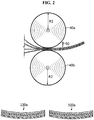
- FIG. 2 is an illustration of a method for manufacturing a curved unit cell using a roll lamination device.
- a negative electrode, a positive electrode and a separator are stacked in a sequential order and consecutively supplied to a roll lamination device (S1), and as they pass through rollers, are compressed to manufacture a unit cell in which the negative electrode, the positive electrode and the separator are bound together (S2).
- S1 a roll lamination device
- S2 The unit cell having passed through the rollers is cut into an optimum size by a cutter 50, and is made ready for use.
- the unit cell is bent and curved along the travel direction of the rollers to form a curve with the predetermined curvature radius R.
- the unit cell(s) has a layered structure and the negative electrode, the positive electrode, and the separator that form each layer includes different materials
- the extent at which each layer reacts, for example, shrinks or elongates changes depending on the process condition such as the temperature, the pressure and/or the rotational speed of the rollers applied during roll compression.
- the optimum control of this process condition makes it possible to manufacture the unit cell having the predetermined curvature radius R.
- a curved electrode assembly or battery was manufactured by pressing a flat plate-shaped electrode assembly or battery using a curved jig.
- stress concentrates on a central part of cell, causing deformation such as a warpage, or a problem with failure to return to the original state, namely, the flat state, by the shape recovery capability.
- the present disclosure employed a method which controls the roll lamination process condition so that a unit cell can stably maintain a curved shape having a uniform curvature radius R.
- the process condition is set for a unit cell to have a desired curvature radius R, and then a unit cell is manufactured according to the process condition being set.
- a plurality of unit cells manufactured under the same roll lamination process condition has a same curvature radius R, or curvature radii R with a small difference according to circumstances.
- the unit cells are appropriately stacked to manufacture a curved electrode assembly having the predetermined curvature radius R. Because it was produced by stacking the curved unit cells, the finally produced curved electrode assembly stably maintains the curved shape and eliminates the possibility of shape deformation, as compared to the curved electrode assembly according to the conventional manufacturing method.
- the roll lamination may be performed under heating condition, and the heating temperature may be appropriately controlled based on the desired curvature radius R or curvature.
- the method may further include the step (S2') for appropriately setting the detailed condition of the roll lamination process, for example, the heating condition, the pressure condition, and/or the rotational speed of the rollers to form the desired curvature radius R in the unit cell.
- the step (S2') for appropriately setting the detailed condition of the roll lamination process, for example, the heating condition, the pressure condition, and/or the rotational speed of the rollers to form the desired curvature radius R in the unit cell.
- a plurality of unit structures having a same curvature radius or a curvature radius that falls within a predetermined range may be manufactured through the step (S2).
- the rollers may be provided with a control device to control the process conditions individually or simultaneously, such as the temperature, the pressure, and/or the rotational speed of rollers.
- an axis of the curve in the curve of the unit cell may be formed parallel to the travel direction (MD) of the rollers.
- the shape of the curved unit cell is a curve in the arc shape of a circle or an oval, where both end parts of the unit cell are bent in a same direction, that is, two are bent upwards or downwards with respect to the plane.
- the unit cell may be a bicell with topmost and bottommost electrode layers of the same polarity, or a full cell with an electrode having topmost and bottommost electrode layers of different polarities.
- the separator may be displaced at the topmost and/or topmost of the unit cell.
- the curve which is bent in the unit cell may be in the shape of an arc which is a segment of a circle or an oval.
- the curvature radius at a central part of the curve may be larger or smaller than the curvature radius at an end part of the curve.
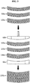
- FIG. 3 is an illustration of the step (S3) for stacking at least two unit cells obtained through the (S2) to manufacture an electrode assembly.
- the (S3) may be performed using a pair of jigs 60a and 60b having a curve.
- the jig includes a lower jig 60a on which a plurality of unit cells is seated and configured to support over the unit cells during compression of the unit cells, and an upper jig b configured to press down the unit cells and the lower jig.
- the lower jig 60a has a concave part with a curvature radius R
- the upper jig 60b has a convex part with a curvature radius R so that it is superimposed on the lower jig 60a.
- the curvature radius R of the jig is equal to the curvature radius R of the unit cells being mounted, or it has a curvature radius R within a predetermined tolerance range for the curvature radius R of the unit cells.
- the curvature radius R of the jig may be preferably equal to the preset curvature radius R in the (S2'), and an electrode assembly having the preset curvature radius R in (S2') may be completed through the compression process using the jig.
- the unit cells do not perfectly match the preset curvature radius R in (S2') and may have other curvature radius R which falls within a predetermined tolerance range.
- the curvature radii R of the plurality of unit cells being stacked may not perfectly match.
- the unit cells may be compressed with the curved jig having the same curvature radius R as the preset curvature radius R to manufacture a curved electrode assembly having a curve formed according to the preset curvature radius R in (S2').
- a plurality of unit cells prepared through (S2) is stacked in a sequential order and mounted on the lower jig 60a.
- the plurality of unit cells may have same or different layer placement.
- a unit cell 100a placed higher has a structure of separator/negative electrode/separator/positive electrode
- a unit cell 100a' placed lower has a structure of separator/negative electrode/separator/positive electrode/separator. This is to place the separator at the uppermost and bottommost layers of the electrode assembly.
- placement of each layer may be appropriately changed according to the final purpose of use of the electrode assembly.
- the unit cells 100a and 100a' mounted on the lower jig 60a are pressed by the upper jig 60b to form an electrode assembly 100b.
- the plurality of unit cells mounted on the lower jig has a same curvature radius R or is included within a predetermined tolerance range.
- the tolerance range is a preset curvature radius R in the step (S2') ⁇ 10%, 5%, or 3%, and specifically, may be calculated by the following [Equation 1].
- Tolerance range of curvature radius R Preset curvature radius R ⁇ Curvature radius R of unit cell Preset curvature radius R ⁇ 100
- heat treatment may be performed in the pressing process, if necessary, and the heating method is not particularly limited.
- a heater may be installed within the jig to perform the heating at the same time as the pressing.
- the pressure and temperature applied during the pressing process is within the range that does cause deterioration of the electrode assembly, preferably the pressure of 150 to 500kgF and the temperature of 10 °C to 90°C.
- the pressing may be performed at room temperature without any separate heating process.
- a maximum difference in the curvature radius R of the stacked unit cells is preferably within 10%.
- a maximum difference in curvature radius representing a curvature radius difference between a unit cell having a longest curvature radius R1 and a unit cell having a shortest curvature radius R2 is within 10%.
- the maximum difference in curvature radius is calculated through the following [Equation 2].
- Maximum difference of curvature radius Longest curvature radius R 1 ⁇ Shortest curvature radius R 2 Longest curvature radius R 1 ⁇ 100
- the curved electrode assembly according to the present disclosure is manufactured by stacking unit cells formed to have a preset curvature radius R in the roll lamination process, it has very high shape stability of curved shape and a low possibility of shape deformation caused by use of the battery.
Landscapes
- Engineering & Computer Science (AREA)
- Manufacturing & Machinery (AREA)
- Chemical & Material Sciences (AREA)
- Chemical Kinetics & Catalysis (AREA)
- Electrochemistry (AREA)
- General Chemical & Material Sciences (AREA)
- Secondary Cells (AREA)
- Physics & Mathematics (AREA)
- Fluid Mechanics (AREA)
- Battery Electrode And Active Subsutance (AREA)
Abstract
Description
- The present application claims priority to Korean Patent Application No.
10-2015-0089126 - There is a growing demand for secondary batteries necessary in mobile electronic devices for information communication such as PDA, mobile phones and laptop computers, or electric bike and electric vehicle, and in keeping up with the trend towards compact and lightweight electronic devices, efforts are being made to commercialize secondary batteries that reduce in size and weight, has high energy density, and can be charged and discharged with high capacity.
- Secondary batteries in typical shape include, for example, prismatic or pouch-type lithium ion secondary batteries with a small thickness for use in electronic devices such as mobile phones. However, prismatic or pouch-type secondary batteries which are in flat shape fail to efficiently use an internal space, and cannot be adapted for secondary battery applications in various shapes and sizes. Therefore, there is the demand for battery cells and battery packs having a shape that efficiently uses an internal space and has high capacity for applications of electronic devices such as mobile phones in streamlined shape and/or size.
- Conventional methods for fabricating a curved battery include a method by which a flat plate-shaped electrode assembly or battery is produced and pressed by a curved jig to fabricate a curved battery.
- In relation to this, there are some earlier technologies that form a curve on an electrode assembly. For example,
US Patent Publication No. 2007/0059595 discloses a battery in which a jelly-roll type electrode assembly has a curved cross section perpendicular to a winding axis. According to the technology, it is disclosed that the curved shape is achieved through thermal compression molding using a concave heater and a convex heater. - Furthermore, Korean Patent Publication No.
2014-0104888 - Generally, if a plurality of plate-shaped stack structures is bent to a predetermined of curvature radius together, an amount of deformation in an inner layer stack structure is larger than that of an outer layer stack structure. In contrast, due to the repeated expansion and contraction of active materials coated on a current collector during charge and discharge, a secondary battery cannot maintain its transformed state in a predetermined shape. Thus, a secondary battery with a structure in which a curvature radius is small, namely, a secondary battery with a structure in which warpage is relatively large may tend to restore the warped state to its original state during repeated charge and discharge, and in this case, current collectors are pressed at their ends by a cell case and are subjected to a strong force enough to penetrate a separator, causing a short.
- When stress concentrates on a central part of a cell, deformation such as a warpage may occur, and particularly, as the curvature radius reduces, this tendency increases, so the range of shapes that can be fabricated is extremely limitative. In addition, because an electrode plate shrinks and expands during continuous charging and discharging of a battery, there is concern about accelerated shape changes of an electrode assembly. Therefore, there is a need to newly develop a method for manufacturing a curved battery with outstanding shape stability.
- The present disclosure is directed to solving the problem of the related art such as the above and the technical problem that has been requested from the past, and specifically, to providing a method for manufacturing a curved electrode assembly with outstanding shape stability. These and other objects and advantages of the present disclosure will be understood from the following description. Also, it will be easily understood that the objects and advantages of the present disclosure may be realized by the means and methods set forth in the appended claims and combinations thereof.
- To achieve the object, there is provided a method for manufacturing a curved electrode assembly.
- According to a first embodiment of the present disclosure, the method for manufacturing a curved electrode assembly includes (S1) preparing a stack structure comprising at least one negative electrode, at least one positive electrode, and at least one separator, wherein the negative electrode and the positive electrode are stacked with the separator interposed between to electrically isolate the negative electrode from the positive electrode, and (S2) performing a compression process by which the stack structure is compressed through a pair of compression rollers, to prepare a unit cell, wherein the unit cell obtained through the step (S2) has a curved shape with a curvature radius R.
- According to a second embodiment of the present disclosure, in the first embodiment, the method further includes (S3) stacking and compressing at least two unit cells obtained through the (S2).
- According to a third embodiment of the present disclosure, in any one of the first and second embodiments, before performing the (S2), the method further includes (S2') setting roll lamination process condition for the unit cell to have a curved shape with a curvature radius R.
- According to a fourth embodiment of the present disclosure, in any one of the first through third embodiments, the step (S2) is performed under heating condition.
- According to a fifth embodiment of the present disclosure, in any one of the first through fourth embodiments, the compression rollers in the (S2) are provided with a control device to control the set temperature, pressure, and/or rotational speed of the rollers.
- According to a sixth embodiment of the present disclosure, in any one of the second through fifth embodiments, the unit cells are obtained through the step (S2) of controlled temperature, pressure, and/or rollers rotational speed.
- According to a seventh embodiment of the present disclosure, in any one of the second through sixth embodiments, the step (S3) is performed using a curved jig, and the jig a) a lower jig on which the electrode stack structure is seated and configured to support over the electrode stack structure during thermal compression, and b) an upper jig configured to press down the electrode stack structure, the lower jig and the upper jig having a curvature radius R.
- According to an eighth embodiment of the present disclosure, in the seventh embodiment, the upper jig and the lower jig are bent in a same direction such that the upper jig is superimposed on the lower jig during compression.
- Also, a ninth embodiment of the present disclosure relates to a method for manufacturing a curved electrode assembly by stacking a plurality of unit cells having a curvature radius R. In the ninth embodiment, a maximum difference in curvature radius representing a curvature radius difference between a unit cell having a longest curvature radius (R1) and a unit cell having a shortest curvature radius (R2) among the unit cells is within 10%.
- According to a tenth embodiment of the present disclosure, in the ninth embodiment, the maximum difference in curvature radius is calculated through the following Equation 2:

- Lastly, according to an eleventh embodiment of the present disclosure, in the ninth or tenth embodiment, the unit cell is prepared by making curved to have a preset curvature radius R by a roll lamination process.
- According to the present disclosure, as a curved electrode assembly is manufactured by stacking a plurality of curved unit cells having a uniform curvature radius R, restoration to the original shape is low and shape stability is high as compared to an electrode assembly manufactured by bending a flat electrode assembly. In addition, as unit cells included in an electrode assembly are produced to have a curve by a roll lamination process under a uniform condition and they have the same curvature radius R or a small difference in curvature radius R, it is possible to easily manufacture an electrode assembly having a desired curvature radius R without excessive deformation of the unit cells.
- The accompanying drawings illustrate a preferred embodiment of the present disclosure, and together with the detailed description, serve to provide further understanding of the principle of the present disclosure, and thus, the present disclosure is not construed as being limited thereto. On the other hand, the shape, size, scale or proportion of elements in the drawings may be exaggerated for clarity.
-
FIG. 1 is a process flowchart of a method for manufacturing an electrode assembly according to a particular embodiment of the present disclosure. -
FIG. 2 is an illustration of a process of manufacturing a unit cell according to a particular embodiment of the present disclosure. -
FIG. 3 is an illustration of a process of manufacturing an electrode assembly according to a particular embodiment of the present disclosure. -
FIG. 4 shows a curvature radius difference between different unit cells. - Hereinafter, the present disclosure will be described in detail with reference to the accompanying drawings. It should be understood that the terms or words used in the specification and the appended claims should not be construed as limited to general and dictionary meanings, but interpreted based on the meanings and concepts corresponding to technical aspects of the present disclosure on the basis of the principle that the inventor is allowed to define terms appropriately for the best explanation. Therefore, the embodiments described herein and illustrations shown in the drawings are just a most preferred embodiment of the present disclosure and do not represent all the technical aspects of the present disclosure, so it should be understood that substitution of various equivalents and modifications could be made at the time a patent application was filed.
- The present disclosure provides a method for manufacturing a curved electrode assembly that is bent to have a curvature radius R. The manufacturing method is characterized in that curved unit cells having a preset curvature radius R are manufactured and at least two of them are stacked to manufacture a curved electrode assembly having the curvature radius R. The electrode assembly manufactured by the manufacturing method of the present disclosure has so good shape stability that it maintains a curved shape.
-
FIG. 1 is a process flowchart showing the method for manufacturing a curved electrode assembly according to the present disclosure. Referring toFIG. 1 , the method for manufacturing a curved electrode assembly according to the present disclosure includes the following steps (S1) to (S3): - (S1) preparing a stack structure including a negative electrode, a positive electrode and a separator;
- (S2) compressing the stack structure to prepare a unit cell; and
- (S3) stacking and compressing at least two unit cells obtained through the (S2).
- According to a particular embodiment of the present disclosure, the stack structure may include at least one negative electrode, at least one positive electrode and at least one separator, and the negative electrode and the positive electrode are stacked such that electrical isolation is maintained by the separator.
- In a particular embodiment of the present disclosure, the step (S2) may be performed using a compression member provided with a pair of rollers. The compression member may be, for example, a roll lamination device. The stack structure is compressed while passing through between the pair of rollers of the roll lamination device, into a unit cell in which the negative electrode, the positive electrode and the separator are bound together. The compression according to a particular embodiment of the present disclosure may be performed under heating condition.
- In the present disclosure, the method for manufacturing a curved electrode assembly presets a curvature radius R that will be applied to the unit cells and controls the process condition for the unit cells to have the preset curvature radius R. For example, by controlling the temperature condition, the pressure condition, and/or the rotational speed of the rollers in the compression process, the unit cells may have a curve with the preset curvature radius R when bent. According to a particular embodiment of the present disclosure, the curve may be in the arc shape of a circle or an oval.
- By mounting the unit cell itself in a battery case having a predetermined curved shape, a curved battery may be manufactured. Alternatively, according to another aspect of the present disclosure, by stacking at least two unit cells, a curved electrode assembly having the predetermined curvature radius R may be manufactured.
- In the present disclosure, the positive electrode may include a positive electrode current collector made of, for example, aluminum (Al) and a positive electrode active material layer formed by coating a positive electrode active material on one surface or both surfaces of the positive electrode current collector. Similarly, the negative electrode may include a current collector made of copper and a negative electrode active material layer formed by coating a negative electrode active material on one surface of the current collector.
- The positive electrode active material includes, for example, a layered positive electrode active material such as LiCoO2, LiNiO2, LiNi1-yCOyO2(0<y<1), LiMO2(M=Mn, Fe), Li(NiaCobMnc)O2(0<a<1, 0<b<1, 0<c<1, a+b+c=1), LiNi1-yMnyO2(O≤y<1); a spinel-type positive electrode active material such as LiMn2O4, LiMn2-zCozO4 (0<z<2), LiMn2-zNizO4(0<z<2), Li(NiaCobMnc)O4(0<a<2, 0<b<2, 0<c<2, a+b+c=2); and an olivine-type positive electrode active material such as LiCoPO4, LiFePO4.
- Also, the negative electrode active material includes, for example, a carbon-based material such as petroleum coke, activated carbon, graphite, non-graphitizable carbon, graphite-based carbon; metal composite oxide such as LixFe2O3(0≤x≤1), LixWO2 (0≤x≤1), SnxMe1-xMe'yOz (Me: Mn, Fe, Pb, Ge; Me': Al, B, P, Si, elements in Groups 1, 2 and 3 of the periodic table, halogen; 0<x≤1; 1≤y≤3; 1≤z≤8); lithium metals; lithium alloys; silicon-based alloys; tin-based alloys; oxide such as SnO, SnO2, PbO, PbO2, Pb2O3, Pb3O4, Sb2O3, Sb2O4, Sb2O5, GeO, GeO2, Bi2O3, Bi2O4, Bi2O5; conductive polymers such as polyacetylene; and Li-Co-Ni based materials.
- In the present disclosure, each of the negative electrode and the positive electrode may have an electrode tab such as a negative electrode tab or positive electrode tab. For example, the electrode tab may be integrally formed with the negative electrode current collector and/or positive electrode current collector, and correspond to a non-coating region which is not coated with an electrode active material. That is, the electrode tab (T) may be formed by cutting a region corresponding to a region un-coated with an electrode active material on the surface of the current collector into an optimum shape.
- In a particular embodiment of the present disclosure, the separator acts as an ion conducting barrier that allows ions to pass through while blocking an electrical contact between the negative electrode and the positive electrode. According to a particular embodiment of the present disclosure, the separator may include a porous polymer substrate having a plurality of micropores. Further, the separator may have a porous coating layer on the surface of the porous polymer substrate, and the porous coating layer includes a plurality of inorganic particles and polymer binder resin. The porous coating layer is a layer in which the inorganic particles are densely packed by point-binding and/or surface-binding through the medium of the binder resin within the coating layer, and the coating layer has a porous structure resulting from interstitial volumes between the inorganic particles.
- The porous polymer substrate is a porous polymer substrate formed of at least one of polymer resins including, but not limited to, for example, polyolefin, polyethyleneterephthalate, polybutyleneterephthalate, polyacetal, polyamide, polycarbonate, polyimide, polyetheretherketone, polyethersulfone, polyphenyleneoxide, polyphenylenesulfide, polyethylenenaphthalene. Also, the porous polymer substrate includes a sheet-type film formed by melting the polymer resin, and a nonwoven fabric produced by putting together filaments obtained by melt-spinning the polymer resin. Preferably, the porous polymer substrate is a porous polymer substrate produced by melting/molding the polymer resin into a sheet shape.
- Subsequently, a particular embodiment of the present disclosure is described with reference to the accompanying drawings.
-
FIG. 2 is an illustration of a method for manufacturing a curved unit cell using a roll lamination device. Referring toFIG. 2 , a negative electrode, a positive electrode and a separator are stacked in a sequential order and consecutively supplied to a roll lamination device (S1), and as they pass through rollers, are compressed to manufacture a unit cell in which the negative electrode, the positive electrode and the separator are bound together (S2). The unit cell having passed through the rollers is cut into an optimum size by acutter 50, and is made ready for use. - According to a particular embodiment of the present disclosure, as the unit cell is compressed by roll lamination, the unit cell is bent and curved along the travel direction of the rollers to form a curve with the predetermined curvature radius R.
- In the present disclosure, as the unit cell(s) has a layered structure and the negative electrode, the positive electrode, and the separator that form each layer includes different materials, the extent at which each layer reacts, for example, shrinks or elongates changes depending on the process condition such as the temperature, the pressure and/or the rotational speed of the rollers applied during roll compression. Thus, the optimum control of this process condition makes it possible to manufacture the unit cell having the predetermined curvature radius R.
- Conventionally, a curved electrode assembly or battery was manufactured by pressing a flat plate-shaped electrode assembly or battery using a curved jig. However, as described previously, in this case, stress concentrates on a central part of cell, causing deformation such as a warpage, or a problem with failure to return to the original state, namely, the flat state, by the shape recovery capability.
- As opposed to the conventional method for manufacturing a curved electrode assembly, the present disclosure employed a method which controls the roll lamination process condition so that a unit cell can stably maintain a curved shape having a uniform curvature radius R. According to a particular embodiment of the present disclosure, before performing the roll lamination process, the process condition is set for a unit cell to have a desired curvature radius R, and then a unit cell is manufactured according to the process condition being set. A plurality of unit cells manufactured under the same roll lamination process condition has a same curvature radius R, or curvature radii R with a small difference according to circumstances. Thus, the unit cells are appropriately stacked to manufacture a curved electrode assembly having the predetermined curvature radius R. Because it was produced by stacking the curved unit cells, the finally produced curved electrode assembly stably maintains the curved shape and eliminates the possibility of shape deformation, as compared to the curved electrode assembly according to the conventional manufacturing method.
- According to a particular embodiment of the present disclosure, the roll lamination may be performed under heating condition, and the heating temperature may be appropriately controlled based on the desired curvature radius R or curvature.
- According to a particular embodiment of the present disclosure, before performing the step (S2), the method may further include the step (S2') for appropriately setting the detailed condition of the roll lamination process, for example, the heating condition, the pressure condition, and/or the rotational speed of the rollers to form the desired curvature radius R in the unit cell.
- For the subsequent process, a plurality of unit structures having a same curvature radius or a curvature radius that falls within a predetermined range may be manufactured through the step (S2). In this stance, for the plurality of manufactured unit cells to maintain a uniform curvature, that is, to have a same curvature radius R or a curvature radius R included within a predetermined tolerance range, it is preferable to uniformly maintain the process condition of roll lamination until a desired number of unit cells is obtained. To this end, the rollers may be provided with a control device to control the process conditions individually or simultaneously, such as the temperature, the pressure, and/or the rotational speed of rollers.
- According to a particular embodiment of the present disclosure, an axis of the curve in the curve of the unit cell may be formed parallel to the travel direction (MD) of the rollers. Also, the shape of the curved unit cell is a curve in the arc shape of a circle or an oval, where both end parts of the unit cell are bent in a same direction, that is, two are bent upwards or downwards with respect to the plane.
- According to a particular embodiment of the present disclosure, the unit cell may be a bicell with topmost and bottommost electrode layers of the same polarity, or a full cell with an electrode having topmost and bottommost electrode layers of different polarities. Also, the separator may be displaced at the topmost and/or topmost of the unit cell.
- In a particular embodiment of the present disclosure, the curve which is bent in the unit cell may be in the shape of an arc which is a segment of a circle or an oval. In the case of the oval shape, the curvature radius at a central part of the curve may be larger or smaller than the curvature radius at an end part of the curve.
-
FIG. 3 is an illustration of the step (S3) for stacking at least two unit cells obtained through the (S2) to manufacture an electrode assembly. Referring toFIG. 3 , the (S3) may be performed using a pair ofjigs lower jig 60a on which a plurality of unit cells is seated and configured to support over the unit cells during compression of the unit cells, and an upper jig b configured to press down the unit cells and the lower jig. Also, thelower jig 60a has a concave part with a curvature radius R, and theupper jig 60b has a convex part with a curvature radius R so that it is superimposed on thelower jig 60a. According to a particular embodiment of the present disclosure, the curvature radius R of the jig is equal to the curvature radius R of the unit cells being mounted, or it has a curvature radius R within a predetermined tolerance range for the curvature radius R of the unit cells. - According to a particular embodiment of the present disclosure, the curvature radius R of the jig may be preferably equal to the preset curvature radius R in the (S2'), and an electrode assembly having the preset curvature radius R in (S2') may be completed through the compression process using the jig.
- In a particular embodiment, the unit cells do not perfectly match the preset curvature radius R in (S2') and may have other curvature radius R which falls within a predetermined tolerance range. Alternatively, the curvature radii R of the plurality of unit cells being stacked may not perfectly match. Thus, in (S2'), the unit cells may be compressed with the curved jig having the same curvature radius R as the preset curvature radius R to manufacture a curved electrode assembly having a curve formed according to the preset curvature radius R in (S2').
- Specifically describing the step (S3) with reference to
FIG. 3 , first, a plurality of unit cells prepared through (S2) is stacked in a sequential order and mounted on thelower jig 60a. In this instance, the plurality of unit cells may have same or different layer placement. In a particular embodiment of the present disclosure, aunit cell 100a placed higher has a structure of separator/negative electrode/separator/positive electrode, and aunit cell 100a' placed lower has a structure of separator/negative electrode/separator/positive electrode/separator. This is to place the separator at the uppermost and bottommost layers of the electrode assembly. Also, in a particular embodiment, placement of each layer may be appropriately changed according to the final purpose of use of the electrode assembly. - Subsequently, the
unit cells lower jig 60a are pressed by theupper jig 60b to form anelectrode assembly 100b. - Preferably, the plurality of unit cells mounted on the lower jig has a same curvature radius R or is included within a predetermined tolerance range. According to a particular embodiment of the present disclosure, the tolerance range is a preset curvature radius R in the step (S2') ± 10%, 5%, or 3%, and specifically, may be calculated by the following [Equation 1].

- In a particular embodiment of the present disclosure, heat treatment may be performed in the pressing process, if necessary, and the heating method is not particularly limited. For example, a heater may be installed within the jig to perform the heating at the same time as the pressing. The pressure and temperature applied during the pressing process is within the range that does cause deterioration of the electrode assembly, preferably the pressure of 150 to 500kgF and the temperature of 10 °C to 90°C. However, to minimize the deterioration of the electrode assembly caused by the heating, the pressing may be performed at room temperature without any separate heating process.
- On the other hand, in a particular embodiment of the present disclosure, in stacking the plurality of curved unit cells to manufacture a curved electrode assembly, a maximum difference in the curvature radius R of the stacked unit cells is preferably within 10%. In other words, among the unit cells, a maximum difference in curvature radius representing a curvature radius difference between a unit cell having a longest curvature radius R1 and a unit cell having a shortest curvature radius R2 is within 10%.
- In the present disclosure, the maximum difference in curvature radius is calculated through the following [Equation 2].

- As described in the foregoing, because the curved electrode assembly according to the present disclosure is manufactured by stacking unit cells formed to have a preset curvature radius R in the roll lamination process, it has very high shape stability of curved shape and a low possibility of shape deformation caused by use of the battery.
- Although the present disclosure has been hereinabove described with respect to a limited number of embodiments and drawings, the present disclosure is not limited thereto, and it is apparent to those skilled in the art that various modifications and changes may be made within the technical scope of the present disclosure and the equivalent scope of the appending claims.
-
- 40a, 40b: Roller
- 50: Cutter
- 100a, 100a': Unit cell
- 100b: Electrode assembly
Claims (11)
- A method for manufacturing a curved electrode assembly, comprising:(S1) preparing a stack structure comprising at least one negative electrode, at least one positive electrode, and at least one separator, wherein the negative electrode and the positive electrode are stacked with the separator interposed between to electrically isolate the negative electrode from the positive electrode; and(S2) performing a compression process by which the stack structure is compressed through a pair of compression rollers, to prepare a unit cell,wherein the unit cell obtained through the step (S2) has a curved shape with a curvature radius R.
- The method for manufacturing a curved electrode assembly according to claim 1, further comprising:(S3) stacking and compressing at least two unit cells obtained through the (S2).
- The method for manufacturing a curved electrode assembly according to claim 1, before performing the (S2), further comprising:(S2') setting roll lamination process condition for the unit cell to have a curved shape with a curvature radius R.
- The method for manufacturing a curved electrode assembly according to claim 1, wherein the step (S2) is performed under heating condition.
- The method for manufacturing a curved electrode assembly according to claim 1, wherein the compression rollers in the (S2) are provided with a control device to control the set temperature, pressure, and/or rotational speed of the rollers.
- The method for manufacturing a curved electrode assembly according to claim 2, wherein the unit cells are obtained through the step (S2) of controlled temperature, pressure, and/or rollers rotational speed.
- The method for manufacturing a curved electrode assembly according to claim 2, wherein the step (S3) is performed using a curved jig, and the jig a) a lower jig on which the electrode stack structure is seated and configured to support over the electrode stack structure during thermal compression, and b) an upper jig configured to press down the electrode stack structure, the lower jig and the upper jig having a curvature radius R.
- The method for manufacturing a curved electrode assembly according to claim 7, wherein the upper jig and the lower jig are bent in a same direction such that the upper jig is superimposed on the lower jig during compression.
- A method for manufacturing a curved electrode assembly, comprising:stacking a plurality of unit cells having a curvature radius R to manufacture an electrode assembly,wherein a maximum difference of curvature radius representing a curvature radius difference between a unit cell having a longest curvature radius (R1) and a unit cell having a shortest curvature radius (R2) among the unit cells is within 10%.
- The method for manufacturing a curved electrode assembly according to claim 9, wherein the maximum difference in curvature radius is calculated through the following [Equation 2]:

- The method for manufacturing a curved electrode assembly according to claim 9, wherein the unit cell is prepared by making curved to have a preset curvature radius R by a roll lamination process.
Applications Claiming Priority (2)
| Application Number | Priority Date | Filing Date | Title |
|---|---|---|---|
| KR20150089126 | 2015-06-23 | ||
| PCT/KR2016/006643 WO2016208970A1 (en) | 2015-06-23 | 2016-06-23 | Method for manufacturing curved electrode assembly |
Publications (3)
| Publication Number | Publication Date |
|---|---|
| EP3261162A1 true EP3261162A1 (en) | 2017-12-27 |
| EP3261162A4 EP3261162A4 (en) | 2018-11-07 |
| EP3261162B1 EP3261162B1 (en) | 2021-11-10 |
Family
ID=57585133
Family Applications (1)
| Application Number | Title | Priority Date | Filing Date |
|---|---|---|---|
| EP16814683.5A Active EP3261162B1 (en) | 2015-06-23 | 2016-06-23 | A method for manufacturing a curved electrode assembly |
Country Status (7)
| Country | Link |
|---|---|
| US (1) | US10566604B2 (en) |
| EP (1) | EP3261162B1 (en) |
| JP (1) | JP6596504B2 (en) |
| KR (1) | KR101963763B1 (en) |
| CN (1) | CN107810569B (en) |
| TW (1) | TWI641176B (en) |
| WO (1) | WO2016208970A1 (en) |
Cited By (1)
| Publication number | Priority date | Publication date | Assignee | Title |
|---|---|---|---|---|
| EP3490048A4 (en) * | 2017-07-18 | 2019-10-23 | LG Chem, Ltd. | METHOD FOR PREPARING ELECTRODE ASSEMBLY AND APPARATUS FOR PRESSING ELECTRODE ASSEMBLY |
Families Citing this family (15)
| Publication number | Priority date | Publication date | Assignee | Title |
|---|---|---|---|---|
| KR20180050108A (en) | 2016-11-04 | 2018-05-14 | 주식회사 엘지화학 | Manufacturing system for laminated film and manufacturing method for laminated film |
| HUE063050T2 (en) * | 2017-07-18 | 2023-12-28 | Lg Energy Solution Ltd | Electrode assembly preparation method |
| KR102244951B1 (en) | 2017-11-21 | 2021-04-27 | 주식회사 엘지화학 | Electrode assembly and secondary battery and manufacturing the same |
| KR102265741B1 (en) * | 2018-03-21 | 2021-06-16 | (주)엘지에너지솔루션 | Manufacturing method for secondary battery and secondary battery manufactured by the same |
| KR102347981B1 (en) | 2018-04-23 | 2022-01-07 | 주식회사 엘지에너지솔루션 | Electrode assembly and method of manufacturing the same |
| KR102500240B1 (en) * | 2018-06-29 | 2023-02-16 | 주식회사 엘지에너지솔루션 | Method of manufacturing electrode assembly |
| CN108878986B (en) * | 2018-07-13 | 2022-10-11 | 广东天劲新能源科技股份有限公司 | Arc-shaped lithium ion battery manufacturing device and manufacturing method |
| CN109411643B (en) | 2018-12-10 | 2021-09-14 | 宁德新能源科技有限公司 | Battery pack |
| KR20200095896A (en) * | 2019-02-01 | 2020-08-11 | 주식회사 엘지화학 | Electrode assembly manufacturing method, and electrode assembly and rechargeable battery manufactured from thereof |
| KR102474625B1 (en) * | 2019-03-21 | 2022-12-05 | 주식회사 엘지에너지솔루션 | Battery manufacturing device and manufacturing method of battery |
| ES2975508T3 (en) | 2019-09-05 | 2024-07-08 | Lg Energy Solution Ltd | Manufacturing method of a secondary battery |
| CN110676506B (en) * | 2019-10-23 | 2020-10-09 | 中兴高能技术有限责任公司 | Manufacturing method of battery cell, battery cell and battery |
| KR102790887B1 (en) * | 2019-12-13 | 2025-04-04 | 주식회사 엘지에너지솔루션 | Adhesion-roll apparatus and pressing method |
| JP7846127B2 (en) | 2021-08-05 | 2026-04-14 | エルジー エナジー ソリューション リミテッド | Electrode assemblies, secondary batteries, battery packs containing them, and automobiles |
| KR102742757B1 (en) * | 2022-12-07 | 2024-12-12 | 주식회사 엘지에너지솔루션 | An electrode assembly and a method of manufacturing the same |
Family Cites Families (14)
| Publication number | Priority date | Publication date | Assignee | Title |
|---|---|---|---|---|
| JPH11307084A (en) * | 1998-02-19 | 1999-11-05 | Matsushita Electric Ind Co Ltd | Organic electrolyte battery |
| JPH11307130A (en) * | 1998-04-24 | 1999-11-05 | Toshiba Battery Co Ltd | Manufacture of curved battery |
| CN1269253C (en) | 2000-11-21 | 2006-08-09 | 索尼株式会社 | Manufacturing method of polymer electrolyte battery |
| JP2008177089A (en) * | 2007-01-19 | 2008-07-31 | Toyota Motor Corp | Fuel cell |
| KR101049841B1 (en) | 2008-03-12 | 2011-07-15 | 주식회사 엘지화학 | Curved battery cell and battery pack comprising the same |
| JP5435131B2 (en) * | 2010-06-28 | 2014-03-05 | 株式会社村田製作所 | Electric storage device and manufacturing method thereof |
| JP5606416B2 (en) | 2011-09-26 | 2014-10-15 | 株式会社東芝 | Electrode pressing apparatus, electrode manufacturing apparatus, and electrode manufacturing method |
| PL2772978T3 (en) | 2012-05-23 | 2019-06-28 | Lg Chem, Ltd. | Electrode assembly and electrochemical device comprising same |
| US10686209B2 (en) * | 2013-02-21 | 2020-06-16 | Samsung Sdi Co., Ltd. | Electrode assembly, battery cell including the electrode assembly, and method of preparing the battery cell |
| TWM482169U (en) * | 2013-07-05 | 2014-07-11 | Power Source Energy Co Ltd | Curved battery |
| US9912005B2 (en) * | 2013-10-29 | 2018-03-06 | Samsung Sdi Co., Ltd. | Method of manufacturing curved secondary battery |
| KR102221805B1 (en) * | 2013-10-29 | 2021-03-03 | 삼성에스디아이 주식회사 | Manufacturing method for curved secondary battery |
| KR101838334B1 (en) * | 2014-02-24 | 2018-03-13 | 주식회사 엘지화학 | A Manufacturing Method for Curved Cell and a Curved Cell thereby |
| WO2016089144A2 (en) * | 2014-12-03 | 2016-06-09 | 주식회사 엘지화학 | Method for manufacturing electrode assembly for secondary battery |
-
2016
- 2016-06-23 KR KR1020160078884A patent/KR101963763B1/en active Active
- 2016-06-23 TW TW105119714A patent/TWI641176B/en active
- 2016-06-23 JP JP2017546643A patent/JP6596504B2/en active Active
- 2016-06-23 US US15/559,972 patent/US10566604B2/en active Active
- 2016-06-23 EP EP16814683.5A patent/EP3261162B1/en active Active
- 2016-06-23 CN CN201680016269.6A patent/CN107810569B/en active Active
- 2016-06-23 WO PCT/KR2016/006643 patent/WO2016208970A1/en not_active Ceased
Cited By (1)
| Publication number | Priority date | Publication date | Assignee | Title |
|---|---|---|---|---|
| EP3490048A4 (en) * | 2017-07-18 | 2019-10-23 | LG Chem, Ltd. | METHOD FOR PREPARING ELECTRODE ASSEMBLY AND APPARATUS FOR PRESSING ELECTRODE ASSEMBLY |
Also Published As
| Publication number | Publication date |
|---|---|
| EP3261162B1 (en) | 2021-11-10 |
| TW201711253A (en) | 2017-03-16 |
| JP6596504B2 (en) | 2019-10-23 |
| TWI641176B (en) | 2018-11-11 |
| KR101963763B1 (en) | 2019-03-29 |
| US20180076442A1 (en) | 2018-03-15 |
| KR20170000368A (en) | 2017-01-02 |
| WO2016208970A1 (en) | 2016-12-29 |
| CN107810569A (en) | 2018-03-16 |
| CN107810569B (en) | 2020-02-21 |
| JP2018511144A (en) | 2018-04-19 |
| EP3261162A4 (en) | 2018-11-07 |
| US10566604B2 (en) | 2020-02-18 |
Similar Documents
| Publication | Publication Date | Title |
|---|---|---|
| EP3261162B1 (en) | A method for manufacturing a curved electrode assembly | |
| US9136556B2 (en) | Electrode assembly of novel structure and process for preparation of the same | |
| EP2232613B1 (en) | Stack/folding-typed electrode assembly and method for preparation of the same | |
| EP3069407B1 (en) | Laminating method | |
| KR101282067B1 (en) | Electrode assembly with asymmetricly coated separator and electrochemical device comprising the same | |
| JP2013504855A (en) | Cable type secondary battery | |
| EP3331085B1 (en) | Cable-type secondary battery and method for manufacturing the same | |
| KR102088648B1 (en) | Manufacturing method of all solid state lithium secondary battery | |
| CN116470242A (en) | Electrode assembly with short-circuit prevention structure and manufacturing method thereof | |
| KR102917432B1 (en) | A solid-state battery and preparation thereof | |
| US12051774B2 (en) | Folding type electrode assembly and method of manufacturing the same | |
| US20240283009A1 (en) | Sulfide electrolyte layer supported dry process electrode layer | |
| US20250132395A1 (en) | Solid-state electrochemical cell components and related systems and methods | |
| KR102442166B1 (en) | Pouch for flexible secondary battery, flexible secondary battery having the same, and method of producing pouch for flexible secondary battery | |
| EP4418393A1 (en) | Solid electrolyte membrane and all-solid-state battery comprising same | |
| KR102886515B1 (en) | Electrode assembly, method for manufacturing thereof, and electrochemical device comprising the same | |
| US20250379249A1 (en) | Apparatus and method for pressurizing battery | |
| CN118104036A (en) | All-solid-state battery and method for manufacturing the same | |
| CA3219607A1 (en) | Electrode assembly and secondary battery including the same | |
| KR20260048132A (en) | Electrode for bipolar battery, manufacturing method thereof, bipolar assemby and bipolar battery comprising the same | |
| CN120149494A (en) | Electricity storage device and method for manufacturing the same |
Legal Events
| Date | Code | Title | Description |
|---|---|---|---|
| STAA | Information on the status of an ep patent application or granted ep patent |
Free format text: STATUS: THE INTERNATIONAL PUBLICATION HAS BEEN MADE |
|
| PUAI | Public reference made under article 153(3) epc to a published international application that has entered the european phase |
Free format text: ORIGINAL CODE: 0009012 |
|
| STAA | Information on the status of an ep patent application or granted ep patent |
Free format text: STATUS: REQUEST FOR EXAMINATION WAS MADE |
|
| 17P | Request for examination filed |
Effective date: 20170918 |
|
| AK | Designated contracting states |
Kind code of ref document: A1 Designated state(s): AL AT BE BG CH CY CZ DE DK EE ES FI FR GB GR HR HU IE IS IT LI LT LU LV MC MK MT NL NO PL PT RO RS SE SI SK SM TR |
|
| AX | Request for extension of the european patent |
Extension state: BA ME |
|
| DAV | Request for validation of the european patent (deleted) | ||
| DAX | Request for extension of the european patent (deleted) | ||
| REG | Reference to a national code |
Ref country code: DE Ref legal event code: R079 Ref document number: 602016066102 Country of ref document: DE Free format text: PREVIOUS MAIN CLASS: H01M0010040000 Ipc: H01M0004040000 |
|
| A4 | Supplementary search report drawn up and despatched |
Effective date: 20181010 |
|
| RIC1 | Information provided on ipc code assigned before grant |
Ipc: H01M 10/0585 20100101ALI20181001BHEP Ipc: H01M 10/04 20060101ALI20181001BHEP Ipc: H01M 4/04 20060101AFI20181001BHEP |
|
| GRAP | Despatch of communication of intention to grant a patent |
Free format text: ORIGINAL CODE: EPIDOSNIGR1 |
|
| STAA | Information on the status of an ep patent application or granted ep patent |
Free format text: STATUS: GRANT OF PATENT IS INTENDED |
|
| INTG | Intention to grant announced |
Effective date: 20210621 |
|
| GRAS | Grant fee paid |
Free format text: ORIGINAL CODE: EPIDOSNIGR3 |
|
| GRAA | (expected) grant |
Free format text: ORIGINAL CODE: 0009210 |
|
| STAA | Information on the status of an ep patent application or granted ep patent |
Free format text: STATUS: THE PATENT HAS BEEN GRANTED |
|
| REG | Reference to a national code |
Ref country code: DE Ref legal event code: R081 Ref document number: 602016066102 Country of ref document: DE Owner name: LG ENERGY SOLUTION, LTD., KR Free format text: FORMER OWNER: LG CHEM, LTD., SEOUL, KR |
|
| AK | Designated contracting states |
Kind code of ref document: B1 Designated state(s): AL AT BE BG CH CY CZ DE DK EE ES FI FR GB GR HR HU IE IS IT LI LT LU LV MC MK MT NL NO PL PT RO RS SE SI SK SM TR |
|
| REG | Reference to a national code |
Ref country code: GB Ref legal event code: FG4D |
|
| REG | Reference to a national code |
Ref country code: AT Ref legal event code: REF Ref document number: 1446897 Country of ref document: AT Kind code of ref document: T Effective date: 20211115 Ref country code: CH Ref legal event code: EP |
|
| RAP4 | Party data changed (patent owner data changed or rights of a patent transferred) |
Owner name: LG CHEM, LTD. |
|
| REG | Reference to a national code |
Ref country code: DE Ref legal event code: R096 Ref document number: 602016066102 Country of ref document: DE |
|
| REG | Reference to a national code |
Ref country code: IE Ref legal event code: FG4D |
|
| REG | Reference to a national code |
Ref country code: SE Ref legal event code: TRGR |
|
| RAP2 | Party data changed (patent owner data changed or rights of a patent transferred) |
Owner name: LG ENERGY SOLUTION LTD. |
|
| REG | Reference to a national code |
Ref country code: LT Ref legal event code: MG9D |
|
| REG | Reference to a national code |
Ref country code: NL Ref legal event code: MP Effective date: 20211110 |
|
| RAP4 | Party data changed (patent owner data changed or rights of a patent transferred) |
Owner name: LG ENERGY SOLUTION, LTD. |
|
| REG | Reference to a national code |
Ref country code: AT Ref legal event code: MK05 Ref document number: 1446897 Country of ref document: AT Kind code of ref document: T Effective date: 20211110 |
|
| PG25 | Lapsed in a contracting state [announced via postgrant information from national office to epo] |
Ref country code: RS Free format text: LAPSE BECAUSE OF FAILURE TO SUBMIT A TRANSLATION OF THE DESCRIPTION OR TO PAY THE FEE WITHIN THE PRESCRIBED TIME-LIMIT Effective date: 20211110 Ref country code: LT Free format text: LAPSE BECAUSE OF FAILURE TO SUBMIT A TRANSLATION OF THE DESCRIPTION OR TO PAY THE FEE WITHIN THE PRESCRIBED TIME-LIMIT Effective date: 20211110 Ref country code: FI Free format text: LAPSE BECAUSE OF FAILURE TO SUBMIT A TRANSLATION OF THE DESCRIPTION OR TO PAY THE FEE WITHIN THE PRESCRIBED TIME-LIMIT Effective date: 20211110 Ref country code: BG Free format text: LAPSE BECAUSE OF FAILURE TO SUBMIT A TRANSLATION OF THE DESCRIPTION OR TO PAY THE FEE WITHIN THE PRESCRIBED TIME-LIMIT Effective date: 20220210 Ref country code: AT Free format text: LAPSE BECAUSE OF FAILURE TO SUBMIT A TRANSLATION OF THE DESCRIPTION OR TO PAY THE FEE WITHIN THE PRESCRIBED TIME-LIMIT Effective date: 20211110 |
|
| PG25 | Lapsed in a contracting state [announced via postgrant information from national office to epo] |
Ref country code: IS Free format text: LAPSE BECAUSE OF FAILURE TO SUBMIT A TRANSLATION OF THE DESCRIPTION OR TO PAY THE FEE WITHIN THE PRESCRIBED TIME-LIMIT Effective date: 20220310 Ref country code: PT Free format text: LAPSE BECAUSE OF FAILURE TO SUBMIT A TRANSLATION OF THE DESCRIPTION OR TO PAY THE FEE WITHIN THE PRESCRIBED TIME-LIMIT Effective date: 20220310 Ref country code: PL Free format text: LAPSE BECAUSE OF FAILURE TO SUBMIT A TRANSLATION OF THE DESCRIPTION OR TO PAY THE FEE WITHIN THE PRESCRIBED TIME-LIMIT Effective date: 20211110 Ref country code: NO Free format text: LAPSE BECAUSE OF FAILURE TO SUBMIT A TRANSLATION OF THE DESCRIPTION OR TO PAY THE FEE WITHIN THE PRESCRIBED TIME-LIMIT Effective date: 20220210 Ref country code: NL Free format text: LAPSE BECAUSE OF FAILURE TO SUBMIT A TRANSLATION OF THE DESCRIPTION OR TO PAY THE FEE WITHIN THE PRESCRIBED TIME-LIMIT Effective date: 20211110 Ref country code: LV Free format text: LAPSE BECAUSE OF FAILURE TO SUBMIT A TRANSLATION OF THE DESCRIPTION OR TO PAY THE FEE WITHIN THE PRESCRIBED TIME-LIMIT Effective date: 20211110 Ref country code: HR Free format text: LAPSE BECAUSE OF FAILURE TO SUBMIT A TRANSLATION OF THE DESCRIPTION OR TO PAY THE FEE WITHIN THE PRESCRIBED TIME-LIMIT Effective date: 20211110 Ref country code: GR Free format text: LAPSE BECAUSE OF FAILURE TO SUBMIT A TRANSLATION OF THE DESCRIPTION OR TO PAY THE FEE WITHIN THE PRESCRIBED TIME-LIMIT Effective date: 20220211 Ref country code: ES Free format text: LAPSE BECAUSE OF FAILURE TO SUBMIT A TRANSLATION OF THE DESCRIPTION OR TO PAY THE FEE WITHIN THE PRESCRIBED TIME-LIMIT Effective date: 20211110 |
|
| PG25 | Lapsed in a contracting state [announced via postgrant information from national office to epo] |
Ref country code: SM Free format text: LAPSE BECAUSE OF FAILURE TO SUBMIT A TRANSLATION OF THE DESCRIPTION OR TO PAY THE FEE WITHIN THE PRESCRIBED TIME-LIMIT Effective date: 20211110 Ref country code: SK Free format text: LAPSE BECAUSE OF FAILURE TO SUBMIT A TRANSLATION OF THE DESCRIPTION OR TO PAY THE FEE WITHIN THE PRESCRIBED TIME-LIMIT Effective date: 20211110 Ref country code: RO Free format text: LAPSE BECAUSE OF FAILURE TO SUBMIT A TRANSLATION OF THE DESCRIPTION OR TO PAY THE FEE WITHIN THE PRESCRIBED TIME-LIMIT Effective date: 20211110 Ref country code: EE Free format text: LAPSE BECAUSE OF FAILURE TO SUBMIT A TRANSLATION OF THE DESCRIPTION OR TO PAY THE FEE WITHIN THE PRESCRIBED TIME-LIMIT Effective date: 20211110 Ref country code: DK Free format text: LAPSE BECAUSE OF FAILURE TO SUBMIT A TRANSLATION OF THE DESCRIPTION OR TO PAY THE FEE WITHIN THE PRESCRIBED TIME-LIMIT Effective date: 20211110 Ref country code: CZ Free format text: LAPSE BECAUSE OF FAILURE TO SUBMIT A TRANSLATION OF THE DESCRIPTION OR TO PAY THE FEE WITHIN THE PRESCRIBED TIME-LIMIT Effective date: 20211110 |
|
| REG | Reference to a national code |
Ref country code: DE Ref legal event code: R097 Ref document number: 602016066102 Country of ref document: DE |
|
| PLBE | No opposition filed within time limit |
Free format text: ORIGINAL CODE: 0009261 |
|
| STAA | Information on the status of an ep patent application or granted ep patent |
Free format text: STATUS: NO OPPOSITION FILED WITHIN TIME LIMIT |
|
| 26N | No opposition filed |
Effective date: 20220811 |
|
| PG25 | Lapsed in a contracting state [announced via postgrant information from national office to epo] |
Ref country code: AL Free format text: LAPSE BECAUSE OF FAILURE TO SUBMIT A TRANSLATION OF THE DESCRIPTION OR TO PAY THE FEE WITHIN THE PRESCRIBED TIME-LIMIT Effective date: 20211110 |
|
| PG25 | Lapsed in a contracting state [announced via postgrant information from national office to epo] |
Ref country code: SI Free format text: LAPSE BECAUSE OF FAILURE TO SUBMIT A TRANSLATION OF THE DESCRIPTION OR TO PAY THE FEE WITHIN THE PRESCRIBED TIME-LIMIT Effective date: 20211110 |
|
| PG25 | Lapsed in a contracting state [announced via postgrant information from national office to epo] |
Ref country code: MC Free format text: LAPSE BECAUSE OF FAILURE TO SUBMIT A TRANSLATION OF THE DESCRIPTION OR TO PAY THE FEE WITHIN THE PRESCRIBED TIME-LIMIT Effective date: 20211110 |
|
| REG | Reference to a national code |
Ref country code: CH Ref legal event code: PL |
|
| REG | Reference to a national code |
Ref country code: BE Ref legal event code: MM Effective date: 20220630 |
|
| PG25 | Lapsed in a contracting state [announced via postgrant information from national office to epo] |
Ref country code: LU Free format text: LAPSE BECAUSE OF NON-PAYMENT OF DUE FEES Effective date: 20220623 Ref country code: LI Free format text: LAPSE BECAUSE OF NON-PAYMENT OF DUE FEES Effective date: 20220630 Ref country code: IE Free format text: LAPSE BECAUSE OF NON-PAYMENT OF DUE FEES Effective date: 20220623 Ref country code: CH Free format text: LAPSE BECAUSE OF NON-PAYMENT OF DUE FEES Effective date: 20220630 |
|
| REG | Reference to a national code |
Ref country code: DE Ref legal event code: R081 Ref document number: 602016066102 Country of ref document: DE Owner name: LG ENERGY SOLUTION, LTD., KR Free format text: FORMER OWNER: LG CHEM, LTD., SEOUL, KR |
|
| PG25 | Lapsed in a contracting state [announced via postgrant information from national office to epo] |
Ref country code: IT Free format text: LAPSE BECAUSE OF FAILURE TO SUBMIT A TRANSLATION OF THE DESCRIPTION OR TO PAY THE FEE WITHIN THE PRESCRIBED TIME-LIMIT Effective date: 20211110 Ref country code: BE Free format text: LAPSE BECAUSE OF NON-PAYMENT OF DUE FEES Effective date: 20220630 |
|
| P01 | Opt-out of the competence of the unified patent court (upc) registered |
Effective date: 20230408 |
|
| REG | Reference to a national code |
Ref country code: GB Ref legal event code: 732E Free format text: REGISTERED BETWEEN 20230901 AND 20230906 |
|
| PG25 | Lapsed in a contracting state [announced via postgrant information from national office to epo] |
Ref country code: HU Free format text: LAPSE BECAUSE OF FAILURE TO SUBMIT A TRANSLATION OF THE DESCRIPTION OR TO PAY THE FEE WITHIN THE PRESCRIBED TIME-LIMIT; INVALID AB INITIO Effective date: 20160623 |
|
| PG25 | Lapsed in a contracting state [announced via postgrant information from national office to epo] |
Ref country code: MK Free format text: LAPSE BECAUSE OF FAILURE TO SUBMIT A TRANSLATION OF THE DESCRIPTION OR TO PAY THE FEE WITHIN THE PRESCRIBED TIME-LIMIT Effective date: 20211110 Ref country code: CY Free format text: LAPSE BECAUSE OF FAILURE TO SUBMIT A TRANSLATION OF THE DESCRIPTION OR TO PAY THE FEE WITHIN THE PRESCRIBED TIME-LIMIT Effective date: 20211110 |
|
| PG25 | Lapsed in a contracting state [announced via postgrant information from national office to epo] |
Ref country code: MT Free format text: LAPSE BECAUSE OF FAILURE TO SUBMIT A TRANSLATION OF THE DESCRIPTION OR TO PAY THE FEE WITHIN THE PRESCRIBED TIME-LIMIT Effective date: 20211110 |
|
| PG25 | Lapsed in a contracting state [announced via postgrant information from national office to epo] |
Ref country code: TR Free format text: LAPSE BECAUSE OF FAILURE TO SUBMIT A TRANSLATION OF THE DESCRIPTION OR TO PAY THE FEE WITHIN THE PRESCRIBED TIME-LIMIT Effective date: 20211110 |
|
| PGFP | Annual fee paid to national office [announced via postgrant information from national office to epo] |
Ref country code: GB Payment date: 20260526 Year of fee payment: 11 |
|
| PGFP | Annual fee paid to national office [announced via postgrant information from national office to epo] |
Ref country code: DE Payment date: 20260520 Year of fee payment: 11 |
|
| PGFP | Annual fee paid to national office [announced via postgrant information from national office to epo] |
Ref country code: SE Payment date: 20260521 Year of fee payment: 11 |
|
| PGFP | Annual fee paid to national office [announced via postgrant information from national office to epo] |
Ref country code: FR Payment date: 20260527 Year of fee payment: 11 |