EP3260802A1 - Nozzle of a device for contact-free treatment of a running fiber web - Google Patents
Nozzle of a device for contact-free treatment of a running fiber web Download PDFInfo
- Publication number
- EP3260802A1 EP3260802A1 EP16175902.2A EP16175902A EP3260802A1 EP 3260802 A1 EP3260802 A1 EP 3260802A1 EP 16175902 A EP16175902 A EP 16175902A EP 3260802 A1 EP3260802 A1 EP 3260802A1
- Authority
- EP
- European Patent Office
- Prior art keywords
- nozzle
- air
- main frame
- frame part
- web
- Prior art date
- Legal status (The legal status is an assumption and is not a legal conclusion. Google has not performed a legal analysis and makes no representation as to the accuracy of the status listed.)
- Granted
Links
Images

Classifications
-
- B—PERFORMING OPERATIONS; TRANSPORTING
- B65—CONVEYING; PACKING; STORING; HANDLING THIN OR FILAMENTARY MATERIAL
- B65H—HANDLING THIN OR FILAMENTARY MATERIAL, e.g. SHEETS, WEBS, CABLES
- B65H20/00—Advancing webs
- B65H20/14—Advancing webs by direct action on web of moving fluid
-
- F—MECHANICAL ENGINEERING; LIGHTING; HEATING; WEAPONS; BLASTING
- F26—DRYING
- F26B—DRYING SOLID MATERIALS OR OBJECTS BY REMOVING LIQUID THEREFROM
- F26B13/00—Machines and apparatus for drying fabrics, fibres, yarns, or other materials in long lengths, with progressive movement
- F26B13/10—Arrangements for feeding, heating or supporting materials; Controlling movement, tension or position of materials
- F26B13/101—Supporting materials without tension, e.g. on or between foraminous belts
- F26B13/104—Supporting materials without tension, e.g. on or between foraminous belts supported by fluid jets only; Fluid blowing arrangements for flotation dryers, e.g. coanda nozzles
-
- B—PERFORMING OPERATIONS; TRANSPORTING
- B65—CONVEYING; PACKING; STORING; HANDLING THIN OR FILAMENTARY MATERIAL
- B65H—HANDLING THIN OR FILAMENTARY MATERIAL, e.g. SHEETS, WEBS, CABLES
- B65H23/00—Registering, tensioning, smoothing or guiding webs
- B65H23/04—Registering, tensioning, smoothing or guiding webs longitudinally
- B65H23/24—Registering, tensioning, smoothing or guiding webs longitudinally by fluid action, e.g. to retard the running web
-
- D—TEXTILES; PAPER
- D21—PAPER-MAKING; PRODUCTION OF CELLULOSE
- D21F—PAPER-MAKING MACHINES; METHODS OF PRODUCING PAPER THEREON
- D21F5/00—Dryer section of machines for making continuous webs of paper
- D21F5/18—Drying webs by hot air
- D21F5/185—Supporting webs in hot air dryers
- D21F5/187—Supporting webs in hot air dryers by air jets
-
- D—TEXTILES; PAPER
- D21—PAPER-MAKING; PRODUCTION OF CELLULOSE
- D21F—PAPER-MAKING MACHINES; METHODS OF PRODUCING PAPER THEREON
- D21F5/00—Dryer section of machines for making continuous webs of paper
- D21F5/18—Drying webs by hot air
- D21F5/185—Supporting webs in hot air dryers
- D21F5/187—Supporting webs in hot air dryers by air jets
- D21F5/188—Blowing devices
-
- D—TEXTILES; PAPER
- D21—PAPER-MAKING; PRODUCTION OF CELLULOSE
- D21H—PULP COMPOSITIONS; PREPARATION THEREOF NOT COVERED BY SUBCLASSES D21C OR D21D; IMPREGNATING OR COATING OF PAPER; TREATMENT OF FINISHED PAPER NOT COVERED BY CLASS B31 OR SUBCLASS D21G; PAPER NOT OTHERWISE PROVIDED FOR
- D21H25/00—After-treatment of paper not provided for in groups D21H17/00 - D21H23/00
- D21H25/04—Physical treatment, e.g. heating, irradiating
- D21H25/06—Physical treatment, e.g. heating, irradiating of impregnated or coated paper
-
- B—PERFORMING OPERATIONS; TRANSPORTING
- B65—CONVEYING; PACKING; STORING; HANDLING THIN OR FILAMENTARY MATERIAL
- B65H—HANDLING THIN OR FILAMENTARY MATERIAL, e.g. SHEETS, WEBS, CABLES
- B65H2406/00—Means using fluid
- B65H2406/10—Means using fluid made only for exhausting gaseous medium
- B65H2406/11—Means using fluid made only for exhausting gaseous medium producing fluidised bed
- B65H2406/112—Means using fluid made only for exhausting gaseous medium producing fluidised bed for handling material along preferably rectilinear path, e.g. nozzle bed for web
-
- B—PERFORMING OPERATIONS; TRANSPORTING
- B65—CONVEYING; PACKING; STORING; HANDLING THIN OR FILAMENTARY MATERIAL
- B65H—HANDLING THIN OR FILAMENTARY MATERIAL, e.g. SHEETS, WEBS, CABLES
- B65H2406/00—Means using fluid
- B65H2406/10—Means using fluid made only for exhausting gaseous medium
- B65H2406/12—Means using fluid made only for exhausting gaseous medium producing gas blast
- B65H2406/122—Nozzles
- B65H2406/1222—Nozzles adjustable impact angle
-
- B—PERFORMING OPERATIONS; TRANSPORTING
- B65—CONVEYING; PACKING; STORING; HANDLING THIN OR FILAMENTARY MATERIAL
- B65H—HANDLING THIN OR FILAMENTARY MATERIAL, e.g. SHEETS, WEBS, CABLES
- B65H2801/00—Application field
- B65H2801/84—Paper-making machines
-
- B—PERFORMING OPERATIONS; TRANSPORTING
- B65—CONVEYING; PACKING; STORING; HANDLING THIN OR FILAMENTARY MATERIAL
- B65H—HANDLING THIN OR FILAMENTARY MATERIAL, e.g. SHEETS, WEBS, CABLES
- B65H51/00—Forwarding filamentary material
- B65H51/16—Devices for entraining material by flow of liquids or gases, e.g. air-blast devices
Definitions
- the invention relates to fiber web technology. More especially the invention relates to a nozzle of a device for contact-free treatment of a running fiber web according to the preamble of claim 1.
- fiber web making processes typically comprise an assembly formed by a number of apparatuses arranged consecutively in the process line.
- a typical production and treatment line comprises a head box, a wire section and a press section as well as a subsequent drying section and a reel-up.
- the production and treatment line can further comprise other devices and sections for finishing the fiber web, for example, a sizer, a calender, and a coating section.
- the production and treatment line also comprises at least one slitter-winder for forming customer rolls as well as a roll packaging apparatus.
- fiber webs are meant for example paper and board webs.
- a device which is capable of correcting any factors that may be related to the run of the web in the transverse direction of the machine, such as wrinkles, folds, and instabilities of the web.
- One way to solve these problems is to produce a web curved in the transverse direction of the machine. In contact-free treatment of a web, this can be achieved by creating a curved carrier face for the air nozzles that are used. Airborne web drying is used, e.g., in various coating applications, in particular in applications in which both sides of the web are treated at the same time.
- a device for contact-free treatment of a running web comprising at least one stationary frame part operating as an air supply chamber comprising opposite side walls, a nozzle-carrier-face unit comprising a carrier face, wherein the opposite side walls of said at least one frame part and said nozzle-carrier- face unit extend substantially in a direction transverse to the running direction of the web, means for coupling said nozzle-carrier-face unit to said at least one frame part, and means for adjustably deflecting said nozzle-carrier-face unit relative to said at least one stationary frame part to provide a curved form for said carrier face in the transverse direction, wherein said nozzle-carrier-face unit is situated inside said at least one stationary frame part between said opposite side walls such that the nozzle-carrier-face unit is displaceable within said at least one stationary frame part and relative to said walls, and said adjustably deflected nozzle-carrier-face unit is fastened to said side walls by means of said coupling means.
- a nozzle orifice arrangement extending across the web and comprising one nozzle slot or a row of successive nozzle orifices extending across the web, and which nozzle orifice arrangements are arranged to blow drying air jets obliquely against each other, or which nozzle orifice arrangements are arranged to blow drying air jets which are guided against each other with the aid of curved Coanda-surfaces, and at least one direct impingement nozzle extending across the web, in which direct impingement nozzle a plurality of nozzle slots or nozzle orifices are formed for blowing drying air mainly perpendicularly against the web, wherein said direct impingement nozzle is combined with said overpressure nozzle on the exit side or on the entrance side thereof in order to form a nozzle assembly such that no discharge passage for discharging wet air is formed between said direct impingement nozzle and said overpressure nozzle; the apparatus comprises on each side of the web two or more of said
- variable air nozzle for treating a fiber web, having a plurality of longitudinally extending air chambers with longitudinal side walls, in which air supply holes are formed, and a covering slide, which has openings functioning with the air supply holes, wherein the air supply holes can be blocked by displacement of the slide.
- An object of the invention is to provide a nozzle of a device for contact-free treatment of a running fiber web, in which the disadvantages of prior art are eliminated or at least minimized.
- a particular object of the invention is to create a simple and easily adjustable nozzle.
- the nozzle of a device for contact-free treatment of a running web comprises a main frame part forming an outer part of the nozzle, which two side chambers on each longitudinal side of the nozzle, each side chamber comprising at least one a nozzle opening for the air blow towards the fiber web, an air channel, through which the air is lead to the side chambers, located at least partially between the side chambers, which air channel is U-shaped and comprises side walls with at least one opening on each side wall for leading the air into the side chambers, wherein a U-shaped inner part is located inside the main frame part and that between inner upper surfaces of the main frame part and outer upper surface of the U-shaped inner part at least one adjustment means comprising a screw and bushings attached by a welding at each end to corresponding upper surface is located at least partially to open or to close the openings.
- the nozzle comprises several adjustment means located apart in the longitudinal direction of the nozzle.
- the nozzle is a longitudinally extending beam like structure.
- the adjustment means the distance between the outer upper surface of the U-shaped inner part and the inner upper surface the main frame part is adjusted.
- the nozzle is formed as welded construction comprising a U-shaped inner part and a main frame part between of which the adjustment mechanism, comprising a screw and bushings, is attached by welding at each end.
- the adjustment mechanism comprising a screw and bushings
- the inner U-shaped part opens/closes the openings in side walls of an outer U-shaped part of the main frame part, whereby the air blows can be regulated without changing the height of the nozzle.
- the nozzle may comprise cross-screws with movement clearance attached between the walls of the inner U-shaped part by which the bending of the nozzle can be adjusted in travel direction of the fiber web.
- At least one of the side walls of the outer U-shaped part of the main frame part comprises longitudinally located, a part spaced openings or a longitudinal opening, which can be opened / closed to any position from fully opened to fully closed by adjusting the locating of side walls of the inner U-shaped part.
- each section is advantageously provided with its adjustment mechanism and thus each section can be adjusted individually. By this amount of air in the air blow can be adjusted.
- the nozzle comprises several spaced apart adjustment mechanisms in longitudinal direction of the nozzle by adjustment of each the curvature of the nozzle in longitudinal direction can be adjusted.
- the distance between the upper surface of the U-shaped inner part and the upper surface of the U-shaped outer part of the main frame part is adjusted.
- the distance of the nozzles upper surface from the surface of the fiber web can be adjusted.
- the nozzle is adjustable during running of the fiber web.
- the invention is achieved an adjustable nozzle with simple construction in which the limitations for adjustability are decreased when compared to nozzles known from prior art.
- the nozzle has an adjustable curvature and efficient adjustment of air blows. Further the height and/or obliqueness of the nozzle in respect of the fiber web can be optimized in mounting the nozzle to the corresponding device of the fiber web production line.
- the nozzle in itself has thus the adjustable curvature independent from its support structures, base frames, attachment system etc.
- the device in accordance with the invention can be utilized in such nozzle constructions used for contact-free web treatment as are supposed to be bent to a curved form in the cross direction of the machine.
- the device in accordance with the invention is particularly suitable for use in various airborne nozzles and especially when a web is dried in connection with two-sided and/or one-sided coating and/or sizing.
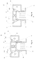
- FIG. 1A -1B is shown a schematical example of a nozzle according to an advantageous example of the invention as a cross section view.
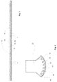
- figure 2 is shown a schematical example of a nozzle according to an advantageous example of the invention as a longitudinal view and
- figure 3 is shown a schematical example of an advantageous application of nozzles according to an advantageous example of the invention in an air turn device of a fiber web production line.
- figure 4 is shown another schematical example of a nozzle according to an advantageous example of the invention as a cross section view.
- figure 5 is shown schematically the example according to figure 4 in a perspective view.
- the nozzle 10 comprises a main frame part 11 that forms the outer part of the nozzle 10.
- the main frame part 11 comprises two side chambers 14, 15 on each longitudinal side of the nozzle 10.
- Each side chamber 14, 15 comprises a nozzle openings 16A, 16B, 17A, 17B for the air blow towards the fiber web (not shown) perpendicularly 16A, 17A and by inclined blows 16B, 17B.
- the main frame part 11 comprises between the side chamber 14, 15 an air channel 20 through which the air is lead to the side chambers 14, 15.
- the air channel 20 is formed U-shaped and its side walls have openings 19, 18 for leading the air into the side chambers 14, 15.
- a U-shaped inner part 13 is located inside the main frame part 11 a U-shaped inner part 13 is located inside the main frame part 11 a U-shaped inner part 13 is located inside the main frame part 11 a U-shaped inner part 13 is located.
- At least one adjustment means 12 is located for adjusting the location of the side walls of the inner part 13 to open or to close the openings 18, 19 of the main frame part 11 as shown in the figures 1A-1B .
- the openings 18, 19 are fully open so that air is passed from the air channel 20 to each of the side chambers 14, 15 and through each nozzle opening 16A, 16B, 17A, 17B as shown by arrows in the figure 1A .
- the distance between the upper surfaces of the main frame part 11 and the U-shaped inner part 13 has been adjusted such that the opening 19 on the left hand side in the figure is fully closed and the opening 18 on the right hand side in the figure is partially opened thus air is passed to the on the right hand side in the figure 1B located side chamber 15 and through the nozzle opening 16A, 16B as shown by the arrows in the figure 1B .
- the nozzle 10 may comprise as the nozzle opening/-s 16A, 16B, 17A, 17B a single or a double slot opening or advantageously there are several substantially circular nozzle openings 16A, 16B, 17A, 17B located spaced apart in at least one line extending substantially in longitudinal direction of the nozzle 10.
- the nozzle 10 is shown as a longitudinal view.
- the nozzle 10 comprises the main frame part 11 and its side chambers 14; 15, one of which can be seen in this longitudinal side view of the nozzle 10, and the inner part 13.
- the nozzle 10 is formed as a longitudinally extending beam like structure.
- curvature of the nozzle can be adjusted by the adjustment means 12.
- the distance between the upper surface of the U-shaped inner part 13 and the upper surface of the U-shaped part of the main frame part 11 is adjusted.
- the distance of the nozzle's 10 upper surface from the surface of the fiber web can be adjusted.
- FIG 3 is shown an air-turn device 25 of a fiber web production line constructed by the nozzles 10 according to the invention. As can be seen the nozzles 10 are located next to each other in curved positions, the curvature can further more accurately be adjusted by the adjustment means 12 of the nozzles 10.
- FIG. 4 - 5 is shown another advantageous example of the nozzle 10 comprising a main frame part 11 that forms the outer part of the nozzle 10.
- the main frame part 11 comprises two side chambers 14, 15 on each longitudinal side of the nozzle 10.
- Each side chamber 14, 15 comprise nozzle openings 17A, 16A for the air blow towards the fiber web (not shown) perpendicularly.
- the main frame part 11 comprises between the side chamber 14, 15 an air channel 20 through which the air is lead to the side chambers 14, 15.
- the air channel 20 is formed U-shaped and its side walls have openings 19, 18 for leading the air into the side chambers 14, 15.
- a U-shaped inner part 13 is located inside the main frame part 11 a U-shaped inner part 13 is located.
- At least one adjustment means 12 is located for adjusting the location of the side walls of the inner part 13 to open or to close the openings 18, 19 of the main frame part 11.
- the openings 18, 19 are fully open so that air is passed from the air channel 20 to each of the side chambers 14, 15 and through each nozzle opening 17A, 16A as shown by arrows in the figure 5 .
- the nozzle 10 comprises several substantially circular nozzle openings 16A, 17A located spaced apart in one line for each side chamber 14, 15 extending substantially in longitudinal direction of the nozzle 10.
- adjustment means 12 for adjusting the curvature of the nozzle 10 advantageously, as shown in figure 5 , there are several adjustment means 12 located apart in the longitudinal direction of the nozzle 10.
- the nozzle 10 is formed as a longitudinally extending beam like structure.
- the curvature of the nozzle 10 can be adjusted by the adjustment means 12.
- the distance between the upper surface of the U-shaped inner part 13 and the upper surface of the U-shaped part of the main frame part 11 is adjusted.
- the distance of the nozzle's 10 upper surface from the surface of the fiber web can be adjusted.
- the nozzle 10 is formed as welded construction comprising a U-shaped inner part 13 and a main frame part 11 between of which the adjustment mechanism 12, comprising a screw 21 and bushings 22, is attached by a welding at each end.
- the adjustment mechanism 12 comprising a screw 21 and bushings 22
- the inner U-shaped part 13 opens/closes the openings 18, 19 in the side walls of the main frame part 11, whereby the air blows can be regulated without changing the height of the nozzle 10.
- dividing plates (not shown) provided in order to divide the nozzle into sections in longitudinal direction of the nozzle, i.e. in cross-direction of the direction of travel of the fiber web.
- each section is advantageously provided with its adjustment mechanism and thus each section can be adjusted individually.
- the nozzle 10 may comprise cross-screws (not shown) with movement clearance attached between the walls of the inner U-shaped part 13 by which the bending of the nozzle 10 can be adjusted in travel direction of the fiber web.
Landscapes
- Engineering & Computer Science (AREA)
- Textile Engineering (AREA)
- Mechanical Engineering (AREA)
- General Engineering & Computer Science (AREA)
- Paper (AREA)
- Treatment Of Fiber Materials (AREA)
Abstract
Description
- The invention relates to fiber web technology. More especially the invention relates to a nozzle of a device for contact-free treatment of a running fiber web according to the preamble of claim 1.
- As known from the prior art fiber web making processes typically comprise an assembly formed by a number of apparatuses arranged consecutively in the process line. A typical production and treatment line comprises a head box, a wire section and a press section as well as a subsequent drying section and a reel-up. The production and treatment line can further comprise other devices and sections for finishing the fiber web, for example, a sizer, a calender, and a coating section. The production and treatment line also comprises at least one slitter-winder for forming customer rolls as well as a roll packaging apparatus. In this description and the following claims by fiber webs are meant for example paper and board webs.
- As is known in the prior art, in some applications of drying, carrying, etc. of a fiber web, for example a paper or board web, a device is needed which is capable of correcting any factors that may be related to the run of the web in the transverse direction of the machine, such as wrinkles, folds, and instabilities of the web. One way to solve these problems is to produce a web curved in the transverse direction of the machine. In contact-free treatment of a web, this can be achieved by creating a curved carrier face for the air nozzles that are used. Airborne web drying is used, e.g., in various coating applications, in particular in applications in which both sides of the web are treated at the same time.
- With regard to the prior art related to airborne web drying, reference is made to publication
EP 0 507 218 A1 , which describes a dryer section including a contact-free web reversing device having a curved form so that the web is turned in the middle of the reversing curve, i.e., corresponding to the middle area of the web, to a greater extent than in lateral areas of the web. Further, in the device, the blow pressures are selected to be higher in the middle area than toward edges areas, so that the web obtains a curved form in the cross direction of the machine. The curved form of the blow pressure profile can be provided either by means of a web reversing device that is accomplished with a curved form or by regulating the blow pressures accordingly. - In publication
EP 0 548 419 A1 is disclosed a device including a nozzle part formed in a manner so as to be adjustable, by means of support adjustable bolts attached at each end and in the middle to a base frame and to the nozzle, in a curved position in the cross direction of the machine. In this known structure the nozzle is bendable against the base frame. - In publication
EP 0 726 220 B1 is disclosed a method for contact-free treatment of a running web by air blowing, said method comprising the steps of blowing air to treat the web through a nozzle-carrier-face unit which comprises a carrier face and which is fastened to a stationary frame part with opposite side walls arranged in a direction transverse to the running direction of the web, said stationary frame part operating as an air supply chamber, and regulating the profile of said nozzle-carrier-face unit in the transverse direction by adjustably bending said nozzle-carrier-face unit to provide a curved form for said carrier face in the transverse direction, wherein said nozzle-carrier-face unit is adjustably bent while being situated inside said frame part between said opposite side walls and while being displaced relative to said side walls. A device for contact-free treatment of a running web, comprising at least one stationary frame part operating as an air supply chamber comprising opposite side walls, a nozzle-carrier-face unit comprising a carrier face, wherein the opposite side walls of said at least one frame part and said nozzle-carrier- face unit extend substantially in a direction transverse to the running direction of the web, means for coupling said nozzle-carrier-face unit to said at least one frame part, and means for adjustably deflecting said nozzle-carrier-face unit relative to said at least one stationary frame part to provide a curved form for said carrier face in the transverse direction, wherein said nozzle-carrier-face unit is situated inside said at least one stationary frame part between said opposite side walls such that the nozzle-carrier-face unit is displaceable within said at least one stationary frame part and relative to said walls, and said adjustably deflected nozzle-carrier-face unit is fastened to said side walls by means of said coupling means. - With further regard to the prior art, reference is made to publication
EP 1218589 A1 , in which is disclosed an airborne web-drying apparatus for drying a travelling coated fiber web, such as a paper or board web, which apparatus comprises a nozzle arrangement including: an overpressure nozzle extending across the web and having on both sides of the nozzle, i.e. on the entrance and exit sides of the nozzle as seen in the web travel direction, a nozzle orifice arrangement extending across the web and comprising one nozzle slot or a row of successive nozzle orifices extending across the web, and which nozzle orifice arrangements are arranged to blow drying air jets obliquely against each other, or which nozzle orifice arrangements are arranged to blow drying air jets which are guided against each other with the aid of curved Coanda-surfaces, and at least one direct impingement nozzle extending across the web, in which direct impingement nozzle a plurality of nozzle slots or nozzle orifices are formed for blowing drying air mainly perpendicularly against the web, wherein said direct impingement nozzle is combined with said overpressure nozzle on the exit side or on the entrance side thereof in order to form a nozzle assembly such that no discharge passage for discharging wet air is formed between said direct impingement nozzle and said overpressure nozzle; the apparatus comprises on each side of the web two or more of said nozzle assemblies spaced-apart from each other in the web travel direction, wherein the gap between two adjacent nozzle assemblies on each side of the web forms a discharge passage for discharging wet air; and the nozzle assemblies are arranged on opposite sides of the web so that opposite each discharge passage between two adjacent nozzle assemblies on one side of the web there is on the other side of the web a nozzle assembly. - In publication
DE 202012005534 U1 is disclosed a variable air nozzle for treating a fiber web, having a plurality of longitudinally extending air chambers with longitudinal side walls, in which air supply holes are formed, and a covering slide, which has openings functioning with the air supply holes, wherein the air supply holes can be blocked by displacement of the slide. - Disadvantages of the from prior art known arrangements are in some cases occurring mechanical uncertainties due to possibly used complicated structures and possible limitations in adjustment. In known arrangements of the prior art there has sometimes also been difficulties to simultaneously achieve optimal curvature adjustability combined with efficiency.
- An object of the invention is to provide a nozzle of a device for contact-free treatment of a running fiber web, in which the disadvantages of prior art are eliminated or at least minimized.
- A particular object of the invention is to create a simple and easily adjustable nozzle.
- It is a further non-limiting object of the present invention to provide a new and improved nozzle in which the regulation of the curved form can be carried out readily with simultaneous efficiency.
- In order to achieve the above objects and those that will come apparent later the nozzle according to the invention is mainly characterized by the features of claim 1. Advantageous aspects and features of the invention are presented in the dependent claims.
- In this description and the claims the word upper have been used as assuming that the nozzle is below the fiber web. It should be noted that the location can also be vice versa or oblique in respect of the fiber web and the word upper should be understood correspondingly. By longitudinal direction of the nozzle is meant direction crosswise in respect of the main travel direction of the fiber web. It should be also noted that instead air other gaseous substances can be used as the blow medium.
- According to the invention the nozzle of a device for contact-free treatment of a running web comprises a main frame part forming an outer part of the nozzle, which two side chambers on each longitudinal side of the nozzle, each side chamber comprising at least one a nozzle opening for the air blow towards the fiber web, an air channel, through which the air is lead to the side chambers, located at least partially between the side chambers, which air channel is U-shaped and comprises side walls with at least one opening on each side wall for leading the air into the side chambers, wherein a U-shaped inner part is located inside the main frame part and that between inner upper surfaces of the main frame part and outer upper surface of the U-shaped inner part at least one adjustment means comprising a screw and bushings attached by a welding at each end to corresponding upper surface is located at least partially to open or to close the openings.
- According to an advantageous feature of the invention the nozzle comprises several adjustment means located apart in the longitudinal direction of the nozzle.
- According to an advantageous feature of the invention the nozzle is a longitudinally extending beam like structure.
- According to an advantageous feature of the invention by the adjustment means the distance between the outer upper surface of the U-shaped inner part and the inner upper surface the main frame part is adjusted.
- According to an advantageous example of the invention the nozzle is formed as welded construction comprising a U-shaped inner part and a main frame part between of which the adjustment mechanism, comprising a screw and bushings, is attached by welding at each end. When the screw is turned the inner U-shaped part opens/closes the openings in side walls of an outer U-shaped part of the main frame part, whereby the air blows can be regulated without changing the height of the nozzle. Advantageously there can be also dividing plates provided in order to divide the nozzle into sections in longitudinal direction of the nozzle, i.e. in cross-direction of the direction of travel of the fiber web. According to a further advantageous feature the nozzle may comprise cross-screws with movement clearance attached between the walls of the inner U-shaped part by which the bending of the nozzle can be adjusted in travel direction of the fiber web.
- According to an advantageous example of the invention at least one of the side walls of the outer U-shaped part of the main frame part comprises longitudinally located, a part spaced openings or a longitudinal opening, which can be opened / closed to any position from fully opened to fully closed by adjusting the locating of side walls of the inner U-shaped part. In case the nozzle is divided into sections by the dividing plates, each section is advantageously provided with its adjustment mechanism and thus each section can be adjusted individually. By this amount of air in the air blow can be adjusted.
- According to an advantageous example of the invention the nozzle comprises several spaced apart adjustment mechanisms in longitudinal direction of the nozzle by adjustment of each the curvature of the nozzle in longitudinal direction can be adjusted. Thus the distance between the upper surface of the U-shaped inner part and the upper surface of the U-shaped outer part of the main frame part is adjusted. Correspondingly the distance of the nozzles upper surface from the surface of the fiber web can be adjusted.
- Advantageously the nozzle is adjustable during running of the fiber web.
- By the invention is achieved an adjustable nozzle with simple construction in which the limitations for adjustability are decreased when compared to nozzles known from prior art. The nozzle has an adjustable curvature and efficient adjustment of air blows. Further the height and/or obliqueness of the nozzle in respect of the fiber web can be optimized in mounting the nozzle to the corresponding device of the fiber web production line. The nozzle in itself has thus the adjustable curvature independent from its support structures, base frames, attachment system etc.
- The device in accordance with the invention can be utilized in such nozzle constructions used for contact-free web treatment as are supposed to be bent to a curved form in the cross direction of the machine. The device in accordance with the invention is particularly suitable for use in various airborne nozzles and especially when a web is dried in connection with two-sided and/or one-sided coating and/or sizing.
- In the following, the invention will be described in detail with reference to some preferred exemplifying embodiments of the invention illustrated in the figures in the accompanying drawings. However, the invention is by no means strictly confined to the details of these embodiments alone.
- In
figures 1A -1B is shown a schematical example of a nozzle according to an advantageous example of the invention as a cross section view. - In
figure 2 is shown a schematical example of a nozzle according to an advantageous example of the invention as a longitudinal view and - In
figure 3 is shown a schematical example of an advantageous application of nozzles according to an advantageous example of the invention in an air turn device of a fiber web production line. - In
figure 4 is shown another schematical example of a nozzle according to an advantageous example of the invention as a cross section view. - In
figure 5 is shown schematically the example according tofigure 4 in a perspective view. - During the course of this description like numbers and signs will be used to identify like elements according to the different views which illustrate the invention. Repetition of some reference signs have been omitted in the figures for clarity reasons.
- As shown in
figures 1A-1B thenozzle 10 comprises amain frame part 11 that forms the outer part of thenozzle 10. Themain frame part 11 comprises twoside chambers nozzle 10. Eachside chamber nozzle openings inclined blows main frame part 11 comprises between theside chamber air channel 20 through which the air is lead to theside chambers air channel 20 is formed U-shaped and its side walls haveopenings side chambers inner part 13 is located. Between the upper surfaces of themain frame part 11 and the U-shaped inner part at least one adjustment means 12 is located for adjusting the location of the side walls of theinner part 13 to open or to close theopenings main frame part 11 as shown in thefigures 1A-1B . Infigure 1A theopenings air channel 20 to each of theside chambers nozzle opening figure 1A . Infigure 1B the distance between the upper surfaces of themain frame part 11 and the U-shapedinner part 13 has been adjusted such that theopening 19 on the left hand side in the figure is fully closed and theopening 18 on the right hand side in the figure is partially opened thus air is passed to the on the right hand side in thefigure 1B locatedside chamber 15 and through thenozzle opening figure 1B . Thenozzle 10 may comprise as the nozzle opening/-s circular nozzle openings nozzle 10. - In
figure 2 is shown thenozzle 10 as a longitudinal view. Thenozzle 10 comprises themain frame part 11 and itsside chambers 14; 15, one of which can be seen in this longitudinal side view of thenozzle 10, and theinner part 13. There is at least one adjustment means 12 for adjusting the curvature of thenozzle 10, advantageously, as shown infigure 2 , there are several adjustment means 12 located apart in the longitudinal direction of thenozzle 10. As can be seen from the figure thenozzle 10 is formed as a longitudinally extending beam like structure. As shown in the figure by dashedline 23, curvature of the nozzle can be adjusted by the adjustment means 12. Thus the distance between the upper surface of the U-shapedinner part 13 and the upper surface of the U-shaped part of themain frame part 11 is adjusted. Correspondingly the distance of the nozzle's 10 upper surface from the surface of the fiber web can be adjusted. - In
figure 3 is shown an air-turn device 25 of a fiber web production line constructed by thenozzles 10 according to the invention. As can be seen thenozzles 10 are located next to each other in curved positions, the curvature can further more accurately be adjusted by the adjustment means 12 of thenozzles 10. - In
figures 4 - 5 is shown another advantageous example of thenozzle 10 comprising amain frame part 11 that forms the outer part of thenozzle 10. Themain frame part 11 comprises twoside chambers nozzle 10. Eachside chamber nozzle openings main frame part 11 comprises between theside chamber air channel 20 through which the air is lead to theside chambers air channel 20 is formed U-shaped and its side walls haveopenings side chambers inner part 13 is located. Between the upper surfaces of themain frame part 11 and the U-shaped inner part at least one adjustment means 12 is located for adjusting the location of the side walls of theinner part 13 to open or to close theopenings main frame part 11. Infigure 4 theopenings air channel 20 to each of theside chambers nozzle opening figure 5 . In this example thenozzle 10 comprises several substantiallycircular nozzle openings side chamber nozzle 10. There is at least one adjustment means 12 for adjusting the curvature of thenozzle 10, advantageously, as shown infigure 5 , there are several adjustment means 12 located apart in the longitudinal direction of thenozzle 10. As can be seen from thefigure 5 thenozzle 10 is formed as a longitudinally extending beam like structure. The curvature of thenozzle 10 can be adjusted by the adjustment means 12. Thus the distance between the upper surface of the U-shapedinner part 13 and the upper surface of the U-shaped part of themain frame part 11 is adjusted. Correspondingly the distance of the nozzle's 10 upper surface from the surface of the fiber web can be adjusted. - According to the present invention the
nozzle 10 is formed as welded construction comprising a U-shapedinner part 13 and amain frame part 11 between of which theadjustment mechanism 12, comprising ascrew 21 andbushings 22, is attached by a welding at each end. When the screw is turned the innerU-shaped part 13 opens/closes theopenings main frame part 11, whereby the air blows can be regulated without changing the height of thenozzle 10. Advantageously there can be also dividing plates (not shown) provided in order to divide the nozzle into sections in longitudinal direction of the nozzle, i.e. in cross-direction of the direction of travel of the fiber web. In case the nozzle is divided into sections by the dividing plates, each section is advantageously provided with its adjustment mechanism and thus each section can be adjusted individually. Thenozzle 10 may comprise cross-screws (not shown) with movement clearance attached between the walls of the innerU-shaped part 13 by which the bending of thenozzle 10 can be adjusted in travel direction of the fiber web. -
- 11 10
- nozzle main frame part
- 12
- adjustment means
- 13
- U-shaped inner part
- 14, 15
- side chamber
- 16A, 16B, 17A, 17B
- nozzle opening
- 18, 19
- opening
- 20
- air channel
- 21
- bushing
- 22
- screw
- 23
- bending line
- 25
- air turn device
Claims (4)
- Nozzle of a device for contact-free treatment of a running web, comprising a main frame part (11) forming an outer part of the nozzle (10), which two side chambers (14, 15) on each longitudinal side of the nozzle (10), each side chamber (14, 15) comprising at least one a nozzle opening (17A, 17B, 16A, 16B) for the air blow towards the fiber web, an air channel (20), through which the air is lead to the side chambers (14, 15), located at least partially between the side chambers (14, 15), which air channel (20) is U-shaped and comprises side walls with at least one opening (19, 18) on each side wall (14, 15) for leading the air into the side chambers (14, 15), characterized in, that a U-shaped inner part (13) is located inside the main frame part (11) and that between inner upper surfaces of the main frame part (11) and outer upper surface of the U-shaped inner part (13) at least one adjustment means (12) comprising a screw (21) and bushings (22) attached by a welding at each end to corresponding upper surface is located at least partially to open or to close the at least one opening (18, 19).
- Nozzle according to claim 1, characterized in, that the nozzle (10) comprises several adjustment means (12) located apart in the longitudinal direction of the nozzle (10).
- Nozzle according to claim 1 or 2, characterized in, that the nozzle (10) is a longitudinally extending beam like structure.
- Nozzle according to any of claims 1 - 3, characterized in, that by the adjustment means (12) the distance between the outer upper surface of the U-shaped inner part (13) and the inner upper surface the main frame part (11) is adjusted.
Priority Applications (5)
| Application Number | Priority Date | Filing Date | Title |
|---|---|---|---|
| EP16175902.2A EP3260802B1 (en) | 2016-06-23 | 2016-06-23 | Nozzle for a device for contact-free treatment of a running fiber web |
| CA2967205A CA2967205A1 (en) | 2016-06-23 | 2017-05-12 | Nozzle of a device for contact-free treatment of a running fiber web |
| JP2017002759U JP3212246U (en) | 2016-06-23 | 2017-06-20 | Equipment nozzle for non-contact processing of traveling fiber web |
| US15/630,932 US10006709B2 (en) | 2016-06-23 | 2017-06-22 | Nozzle of a device for contact—free treatment of a running fiber web |
| CN201720743790.1U CN207103078U (en) | 2016-06-23 | 2017-06-23 | Nozzle for the device of the contactless processing of the fiber web of operation |
Applications Claiming Priority (1)
| Application Number | Priority Date | Filing Date | Title |
|---|---|---|---|
| EP16175902.2A EP3260802B1 (en) | 2016-06-23 | 2016-06-23 | Nozzle for a device for contact-free treatment of a running fiber web |
Publications (2)
| Publication Number | Publication Date |
|---|---|
| EP3260802A1 true EP3260802A1 (en) | 2017-12-27 |
| EP3260802B1 EP3260802B1 (en) | 2019-10-09 |
Family
ID=56235658
Family Applications (1)
| Application Number | Title | Priority Date | Filing Date |
|---|---|---|---|
| EP16175902.2A Active EP3260802B1 (en) | 2016-06-23 | 2016-06-23 | Nozzle for a device for contact-free treatment of a running fiber web |
Country Status (5)
| Country | Link |
|---|---|
| US (1) | US10006709B2 (en) |
| EP (1) | EP3260802B1 (en) |
| JP (1) | JP3212246U (en) |
| CN (1) | CN207103078U (en) |
| CA (1) | CA2967205A1 (en) |
Families Citing this family (2)
| Publication number | Priority date | Publication date | Assignee | Title |
|---|---|---|---|---|
| EP3260802B1 (en) * | 2016-06-23 | 2019-10-09 | Valmet Technologies Oy | Nozzle for a device for contact-free treatment of a running fiber web |
| CN112499346A (en) * | 2020-12-28 | 2021-03-16 | 滁州卷烟材料厂 | Air supporting type aluminum foil paper leveling mechanism for cigarettes |
Citations (6)
| Publication number | Priority date | Publication date | Assignee | Title |
|---|---|---|---|---|
| DE2934967A1 (en) * | 1978-08-29 | 1980-03-13 | Caratsch Hans Peter | FLOATING DRYER |
| EP0548419A1 (en) | 1990-06-02 | 1993-06-30 | Spooner Industries Limited | Improved air turn |
| EP0726220B1 (en) | 1995-02-10 | 1999-04-07 | Valmet Corporation | Method and device in contact-free treatment of a web |
| WO2001002643A1 (en) * | 1999-06-30 | 2001-01-11 | Metso Paper, Inc. | Nozzle arrangement in airborne web-drying and method for improving heat transfer in airborne web-drying |
| JP2002273272A (en) * | 2001-03-16 | 2002-09-24 | Ishikawajima Harima Heavy Ind Co Ltd | Air blow nozzle |
| DE202012005534U1 (en) | 2012-06-06 | 2012-07-17 | Metso Paper, Inc. | Variable ventilation nozzle for the treatment of a fibrous web |
Family Cites Families (22)
| Publication number | Priority date | Publication date | Assignee | Title |
|---|---|---|---|---|
| US3303576A (en) * | 1965-05-28 | 1967-02-14 | Procter & Gamble | Apparatus for drying porous paper |
| JPS5241370B2 (en) * | 1973-09-14 | 1977-10-18 | ||
| US4952128A (en) * | 1987-09-22 | 1990-08-28 | Chicopee | Transverse web forming apparatus |
| DE4110875A1 (en) | 1991-04-04 | 1992-10-08 | Voith Gmbh J M | DRY LOT |
| FI105533B (en) * | 1992-10-26 | 2000-09-15 | Valmet Paper Machinery Inc | Spray coating device and method |
| FI94271C (en) * | 1992-11-03 | 1995-08-10 | Valmet Paper Machinery Inc | Method of cleaning rollers and roller cleaning device |
| FI94176C (en) * | 1992-12-16 | 1995-07-25 | Valmet Paper Machinery Inc | Method and apparatus for tracking the edge of a moving track |
| DE4401582A1 (en) * | 1994-01-20 | 1994-06-09 | Voith Gmbh J M | Method of continuous delivering of fluid-gas mixture - involves having gas separated from fluid-gas flow between first and second level above which it is directed |
| US5588223A (en) * | 1994-06-14 | 1996-12-31 | Asea Brown Boveri Inc. | Restrained paper dryer |
| FI112509B (en) * | 1994-06-15 | 2003-12-15 | Metso Paper Inc | Gap grinder in a paper machine |
| FR2732044B1 (en) * | 1995-03-20 | 1997-04-30 | Kaysersberg Sa | METHOD FOR WRINGING A SHEET OF CELLULOSIC MATERIAL BY HOT AIR PASSING THROUGH UNDER A HIGH VACUUM |
| FI98944C (en) * | 1995-10-25 | 1997-09-10 | Valmet Corp | Method and apparatus for drying the coating of a paper web or equivalent |
| US6119362A (en) * | 1996-06-19 | 2000-09-19 | Valmet Corporation | Arrangements for impingement drying and/or through-drying of a paper or material web |
| FI107549B (en) * | 1996-06-19 | 2001-08-31 | Metso Paper Inc | Method and apparatus in connection with blow-drying and / or blow-drying of paper web or the corresponding web-shaped material |
| FI101985B (en) * | 1996-12-10 | 1998-09-30 | Valmet Corp | Method and apparatus for drying fiber web |
| FI971899A7 (en) * | 1997-05-02 | 1998-11-03 | Sunds Defibrator Panelhandling | Method and apparatus for treating sheet-like material with a gaseous substance |
| US6360758B1 (en) * | 1999-09-10 | 2002-03-26 | Metso Paper, Inc. | Cleaning device in paper machines, board machines or other similar machines for cleaning a fabric, such as wire or felt |
| US6314659B1 (en) * | 1999-12-14 | 2001-11-13 | Valmet Inc. | Device and method for protecting a carrying fabric |
| US6485612B1 (en) * | 2001-05-18 | 2002-11-26 | Voith Paper, Inc. | Air press assembly for use in a paper-making machine |
| JP2010261120A (en) * | 2009-05-02 | 2010-11-18 | Seed:Kk | Paper making apparatus and used paper recycling apparatus for used paper recycling apparatus |
| SE536662C2 (en) * | 2012-11-13 | 2014-05-06 | Valmet Aktiebolag | Yankee cylinder made of steel |
| EP3260802B1 (en) * | 2016-06-23 | 2019-10-09 | Valmet Technologies Oy | Nozzle for a device for contact-free treatment of a running fiber web |
-
2016
- 2016-06-23 EP EP16175902.2A patent/EP3260802B1/en active Active
-
2017
- 2017-05-12 CA CA2967205A patent/CA2967205A1/en not_active Abandoned
- 2017-06-20 JP JP2017002759U patent/JP3212246U/en active Active
- 2017-06-22 US US15/630,932 patent/US10006709B2/en active Active
- 2017-06-23 CN CN201720743790.1U patent/CN207103078U/en active Active
Patent Citations (7)
| Publication number | Priority date | Publication date | Assignee | Title |
|---|---|---|---|---|
| DE2934967A1 (en) * | 1978-08-29 | 1980-03-13 | Caratsch Hans Peter | FLOATING DRYER |
| EP0548419A1 (en) | 1990-06-02 | 1993-06-30 | Spooner Industries Limited | Improved air turn |
| EP0726220B1 (en) | 1995-02-10 | 1999-04-07 | Valmet Corporation | Method and device in contact-free treatment of a web |
| WO2001002643A1 (en) * | 1999-06-30 | 2001-01-11 | Metso Paper, Inc. | Nozzle arrangement in airborne web-drying and method for improving heat transfer in airborne web-drying |
| EP1218589A1 (en) | 1999-06-30 | 2002-07-03 | Metso Paper, Inc.(Reg.No. 763281) | Airborne web-drying apparatus and method for improving heat transfer in an airborne web-drying apparatus |
| JP2002273272A (en) * | 2001-03-16 | 2002-09-24 | Ishikawajima Harima Heavy Ind Co Ltd | Air blow nozzle |
| DE202012005534U1 (en) | 2012-06-06 | 2012-07-17 | Metso Paper, Inc. | Variable ventilation nozzle for the treatment of a fibrous web |
Also Published As
| Publication number | Publication date |
|---|---|
| JP3212246U (en) | 2017-08-31 |
| CN207103078U (en) | 2018-03-16 |
| US10006709B2 (en) | 2018-06-26 |
| EP3260802B1 (en) | 2019-10-09 |
| CA2967205A1 (en) | 2017-12-23 |
| US20170370644A1 (en) | 2017-12-28 |
Similar Documents
| Publication | Publication Date | Title |
|---|---|---|
| EP0743996B1 (en) | Paper coating device | |
| EP0507218B1 (en) | Dryer section | |
| DE69219707T2 (en) | Vacuum nozzle arrangement for treating webs | |
| EP3260802B1 (en) | Nozzle for a device for contact-free treatment of a running fiber web | |
| EP1903142B1 (en) | System for widening a fibre web, method for controlling the transfer of a web tail and machine for producing a sheet of fibrous material | |
| EP0638159B1 (en) | Multi-functional nozzle blow box | |
| JPH03887A (en) | Method and apparatus for reinforcing threading of web used in dry part of paper machine | |
| JPH10165873A (en) | Apparatus for directly or indirectly applying a liquid or pasty application medium to a moving material web, especially consisting of paper or cardboard | |
| FI110627B (en) | A method for blowing steam against a paper web and a steam box for a paper machine | |
| EP2792787B1 (en) | Method and apparatus for distributing steam | |
| EP2622137A1 (en) | Device for directly or indirectly applying a liquid to pasty application medium and method for operating said type of device | |
| JP2011508111A (en) | Apparatus and method for controlling negative pressure in a drying section of a paper machine or the like | |
| WO2004074148A2 (en) | Device for guiding a moving web of fibrous material | |
| EP2868802A1 (en) | Arrangement of a fiber web production line and method of a fiber web production line | |
| DE69500781T2 (en) | Air guide vanes for a pneumatic turning bar | |
| CA2169206C (en) | Method and device in contact-free treatment of a web | |
| EP2161373B1 (en) | Device for stabilizing the run of a web in a paper machine and method of manufacturing said device | |
| GB1584770A (en) | Guide device for flexible webs | |
| DE102004003899A1 (en) | Device for guiding a running fibrous web | |
| EP2508672B1 (en) | Device for transferring a web in a station of a web production or processing machine | |
| EP4653614A1 (en) | Drying group and a drying section for a fiber web production line | |
| EP1041026B1 (en) | Device for contact-free turning a running web | |
| EP4653613A1 (en) | Pocket space end sealing system | |
| DE10322521A1 (en) | Web guiding and / or sealing device | |
| DE10142519A1 (en) | Assembly to detach a paper/cardboard web from a roller, to travel to the next workstation, has a blower jet and a guide wall to keep the high speed web taut in its path to the next production stage |
Legal Events
| Date | Code | Title | Description |
|---|---|---|---|
| PUAI | Public reference made under article 153(3) epc to a published international application that has entered the european phase |
Free format text: ORIGINAL CODE: 0009012 |
|
| STAA | Information on the status of an ep patent application or granted ep patent |
Free format text: STATUS: THE APPLICATION HAS BEEN PUBLISHED |
|
| AK | Designated contracting states |
Kind code of ref document: A1 Designated state(s): AL AT BE BG CH CY CZ DE DK EE ES FI FR GB GR HR HU IE IS IT LI LT LU LV MC MK MT NL NO PL PT RO RS SE SI SK SM TR |
|
| AX | Request for extension of the european patent |
Extension state: BA ME |
|
| STAA | Information on the status of an ep patent application or granted ep patent |
Free format text: STATUS: REQUEST FOR EXAMINATION WAS MADE |
|
| 17P | Request for examination filed |
Effective date: 20180605 |
|
| RBV | Designated contracting states (corrected) |
Designated state(s): AL AT BE BG CH CY CZ DE DK EE ES FI FR GB GR HR HU IE IS IT LI LT LU LV MC MK MT NL NO PL PT RO RS SE SI SK SM TR |
|
| GRAP | Despatch of communication of intention to grant a patent |
Free format text: ORIGINAL CODE: EPIDOSNIGR1 |
|
| STAA | Information on the status of an ep patent application or granted ep patent |
Free format text: STATUS: GRANT OF PATENT IS INTENDED |
|
| INTG | Intention to grant announced |
Effective date: 20190528 |
|
| GRAS | Grant fee paid |
Free format text: ORIGINAL CODE: EPIDOSNIGR3 |
|
| GRAA | (expected) grant |
Free format text: ORIGINAL CODE: 0009210 |
|
| STAA | Information on the status of an ep patent application or granted ep patent |
Free format text: STATUS: THE PATENT HAS BEEN GRANTED |
|
| AK | Designated contracting states |
Kind code of ref document: B1 Designated state(s): AL AT BE BG CH CY CZ DE DK EE ES FI FR GB GR HR HU IE IS IT LI LT LU LV MC MK MT NL NO PL PT RO RS SE SI SK SM TR |
|
| REG | Reference to a national code |
Ref country code: GB Ref legal event code: FG4D |
|
| REG | Reference to a national code |
Ref country code: CH Ref legal event code: EP |
|
| REG | Reference to a national code |
Ref country code: IE Ref legal event code: FG4D |
|
| REG | Reference to a national code |
Ref country code: DE Ref legal event code: R096 Ref document number: 602016021973 Country of ref document: DE |
|
| REG | Reference to a national code |
Ref country code: AT Ref legal event code: REF Ref document number: 1189323 Country of ref document: AT Kind code of ref document: T Effective date: 20191115 |
|
| REG | Reference to a national code |
Ref country code: NL Ref legal event code: MP Effective date: 20191009 |
|
| REG | Reference to a national code |
Ref country code: LT Ref legal event code: MG4D |
|
| PG25 | Lapsed in a contracting state [announced via postgrant information from national office to epo] |
Ref country code: NO Free format text: LAPSE BECAUSE OF FAILURE TO SUBMIT A TRANSLATION OF THE DESCRIPTION OR TO PAY THE FEE WITHIN THE PRESCRIBED TIME-LIMIT Effective date: 20200109 Ref country code: PT Free format text: LAPSE BECAUSE OF FAILURE TO SUBMIT A TRANSLATION OF THE DESCRIPTION OR TO PAY THE FEE WITHIN THE PRESCRIBED TIME-LIMIT Effective date: 20200210 Ref country code: PL Free format text: LAPSE BECAUSE OF FAILURE TO SUBMIT A TRANSLATION OF THE DESCRIPTION OR TO PAY THE FEE WITHIN THE PRESCRIBED TIME-LIMIT Effective date: 20191009 Ref country code: LT Free format text: LAPSE BECAUSE OF FAILURE TO SUBMIT A TRANSLATION OF THE DESCRIPTION OR TO PAY THE FEE WITHIN THE PRESCRIBED TIME-LIMIT Effective date: 20191009 Ref country code: ES Free format text: LAPSE BECAUSE OF FAILURE TO SUBMIT A TRANSLATION OF THE DESCRIPTION OR TO PAY THE FEE WITHIN THE PRESCRIBED TIME-LIMIT Effective date: 20191009 Ref country code: SE Free format text: LAPSE BECAUSE OF FAILURE TO SUBMIT A TRANSLATION OF THE DESCRIPTION OR TO PAY THE FEE WITHIN THE PRESCRIBED TIME-LIMIT Effective date: 20191009 Ref country code: NL Free format text: LAPSE BECAUSE OF FAILURE TO SUBMIT A TRANSLATION OF THE DESCRIPTION OR TO PAY THE FEE WITHIN THE PRESCRIBED TIME-LIMIT Effective date: 20191009 Ref country code: LV Free format text: LAPSE BECAUSE OF FAILURE TO SUBMIT A TRANSLATION OF THE DESCRIPTION OR TO PAY THE FEE WITHIN THE PRESCRIBED TIME-LIMIT Effective date: 20191009 Ref country code: BG Free format text: LAPSE BECAUSE OF FAILURE TO SUBMIT A TRANSLATION OF THE DESCRIPTION OR TO PAY THE FEE WITHIN THE PRESCRIBED TIME-LIMIT Effective date: 20200109 Ref country code: GR Free format text: LAPSE BECAUSE OF FAILURE TO SUBMIT A TRANSLATION OF THE DESCRIPTION OR TO PAY THE FEE WITHIN THE PRESCRIBED TIME-LIMIT Effective date: 20200110 Ref country code: FI Free format text: LAPSE BECAUSE OF FAILURE TO SUBMIT A TRANSLATION OF THE DESCRIPTION OR TO PAY THE FEE WITHIN THE PRESCRIBED TIME-LIMIT Effective date: 20191009 |
|
| PG25 | Lapsed in a contracting state [announced via postgrant information from national office to epo] |
Ref country code: IS Free format text: LAPSE BECAUSE OF FAILURE TO SUBMIT A TRANSLATION OF THE DESCRIPTION OR TO PAY THE FEE WITHIN THE PRESCRIBED TIME-LIMIT Effective date: 20200224 Ref country code: RS Free format text: LAPSE BECAUSE OF FAILURE TO SUBMIT A TRANSLATION OF THE DESCRIPTION OR TO PAY THE FEE WITHIN THE PRESCRIBED TIME-LIMIT Effective date: 20191009 Ref country code: HR Free format text: LAPSE BECAUSE OF FAILURE TO SUBMIT A TRANSLATION OF THE DESCRIPTION OR TO PAY THE FEE WITHIN THE PRESCRIBED TIME-LIMIT Effective date: 20191009 |
|
| PG25 | Lapsed in a contracting state [announced via postgrant information from national office to epo] |
Ref country code: AL Free format text: LAPSE BECAUSE OF FAILURE TO SUBMIT A TRANSLATION OF THE DESCRIPTION OR TO PAY THE FEE WITHIN THE PRESCRIBED TIME-LIMIT Effective date: 20191009 |
|
| REG | Reference to a national code |
Ref country code: DE Ref legal event code: R097 Ref document number: 602016021973 Country of ref document: DE |
|
| PG2D | Information on lapse in contracting state deleted |
Ref country code: IS |
|
| PG25 | Lapsed in a contracting state [announced via postgrant information from national office to epo] |
Ref country code: DK Free format text: LAPSE BECAUSE OF FAILURE TO SUBMIT A TRANSLATION OF THE DESCRIPTION OR TO PAY THE FEE WITHIN THE PRESCRIBED TIME-LIMIT Effective date: 20191009 Ref country code: EE Free format text: LAPSE BECAUSE OF FAILURE TO SUBMIT A TRANSLATION OF THE DESCRIPTION OR TO PAY THE FEE WITHIN THE PRESCRIBED TIME-LIMIT Effective date: 20191009 Ref country code: RO Free format text: LAPSE BECAUSE OF FAILURE TO SUBMIT A TRANSLATION OF THE DESCRIPTION OR TO PAY THE FEE WITHIN THE PRESCRIBED TIME-LIMIT Effective date: 20191009 Ref country code: CZ Free format text: LAPSE BECAUSE OF FAILURE TO SUBMIT A TRANSLATION OF THE DESCRIPTION OR TO PAY THE FEE WITHIN THE PRESCRIBED TIME-LIMIT Effective date: 20191009 Ref country code: IS Free format text: LAPSE BECAUSE OF FAILURE TO SUBMIT A TRANSLATION OF THE DESCRIPTION OR TO PAY THE FEE WITHIN THE PRESCRIBED TIME-LIMIT Effective date: 20200209 |
|
| PLBE | No opposition filed within time limit |
Free format text: ORIGINAL CODE: 0009261 |
|
| STAA | Information on the status of an ep patent application or granted ep patent |
Free format text: STATUS: NO OPPOSITION FILED WITHIN TIME LIMIT |
|
| PG25 | Lapsed in a contracting state [announced via postgrant information from national office to epo] |
Ref country code: SM Free format text: LAPSE BECAUSE OF FAILURE TO SUBMIT A TRANSLATION OF THE DESCRIPTION OR TO PAY THE FEE WITHIN THE PRESCRIBED TIME-LIMIT Effective date: 20191009 Ref country code: IT Free format text: LAPSE BECAUSE OF FAILURE TO SUBMIT A TRANSLATION OF THE DESCRIPTION OR TO PAY THE FEE WITHIN THE PRESCRIBED TIME-LIMIT Effective date: 20191009 Ref country code: SK Free format text: LAPSE BECAUSE OF FAILURE TO SUBMIT A TRANSLATION OF THE DESCRIPTION OR TO PAY THE FEE WITHIN THE PRESCRIBED TIME-LIMIT Effective date: 20191009 |
|
| 26N | No opposition filed |
Effective date: 20200710 |
|
| PG25 | Lapsed in a contracting state [announced via postgrant information from national office to epo] |
Ref country code: SI Free format text: LAPSE BECAUSE OF FAILURE TO SUBMIT A TRANSLATION OF THE DESCRIPTION OR TO PAY THE FEE WITHIN THE PRESCRIBED TIME-LIMIT Effective date: 20191009 |
|
| PG25 | Lapsed in a contracting state [announced via postgrant information from national office to epo] |
Ref country code: MC Free format text: LAPSE BECAUSE OF FAILURE TO SUBMIT A TRANSLATION OF THE DESCRIPTION OR TO PAY THE FEE WITHIN THE PRESCRIBED TIME-LIMIT Effective date: 20191009 |
|
| REG | Reference to a national code |
Ref country code: CH Ref legal event code: PL |
|
| PG25 | Lapsed in a contracting state [announced via postgrant information from national office to epo] |
Ref country code: LU Free format text: LAPSE BECAUSE OF NON-PAYMENT OF DUE FEES Effective date: 20200623 |
|
| REG | Reference to a national code |
Ref country code: BE Ref legal event code: MM Effective date: 20200630 |
|
| PG25 | Lapsed in a contracting state [announced via postgrant information from national office to epo] |
Ref country code: CH Free format text: LAPSE BECAUSE OF NON-PAYMENT OF DUE FEES Effective date: 20200630 Ref country code: LI Free format text: LAPSE BECAUSE OF NON-PAYMENT OF DUE FEES Effective date: 20200630 Ref country code: IE Free format text: LAPSE BECAUSE OF NON-PAYMENT OF DUE FEES Effective date: 20200623 |
|
| PG25 | Lapsed in a contracting state [announced via postgrant information from national office to epo] |
Ref country code: BE Free format text: LAPSE BECAUSE OF NON-PAYMENT OF DUE FEES Effective date: 20200630 |
|
| REG | Reference to a national code |
Ref country code: AT Ref legal event code: UEP Ref document number: 1189323 Country of ref document: AT Kind code of ref document: T Effective date: 20191009 |
|
| PG25 | Lapsed in a contracting state [announced via postgrant information from national office to epo] |
Ref country code: TR Free format text: LAPSE BECAUSE OF FAILURE TO SUBMIT A TRANSLATION OF THE DESCRIPTION OR TO PAY THE FEE WITHIN THE PRESCRIBED TIME-LIMIT Effective date: 20191009 Ref country code: MT Free format text: LAPSE BECAUSE OF FAILURE TO SUBMIT A TRANSLATION OF THE DESCRIPTION OR TO PAY THE FEE WITHIN THE PRESCRIBED TIME-LIMIT Effective date: 20191009 Ref country code: CY Free format text: LAPSE BECAUSE OF FAILURE TO SUBMIT A TRANSLATION OF THE DESCRIPTION OR TO PAY THE FEE WITHIN THE PRESCRIBED TIME-LIMIT Effective date: 20191009 |
|
| PG25 | Lapsed in a contracting state [announced via postgrant information from national office to epo] |
Ref country code: MK Free format text: LAPSE BECAUSE OF FAILURE TO SUBMIT A TRANSLATION OF THE DESCRIPTION OR TO PAY THE FEE WITHIN THE PRESCRIBED TIME-LIMIT Effective date: 20191009 |
|
| PGFP | Annual fee paid to national office [announced via postgrant information from national office to epo] |
Ref country code: DE Payment date: 20250618 Year of fee payment: 10 |
|
| PGFP | Annual fee paid to national office [announced via postgrant information from national office to epo] |
Ref country code: GB Payment date: 20250618 Year of fee payment: 10 |
|
| PGFP | Annual fee paid to national office [announced via postgrant information from national office to epo] |
Ref country code: FR Payment date: 20250625 Year of fee payment: 10 |
|
| PGFP | Annual fee paid to national office [announced via postgrant information from national office to epo] |
Ref country code: AT Payment date: 20250620 Year of fee payment: 10 |