EP0548419A1 - Improved air turn - Google Patents
Improved air turn Download PDFInfo
- Publication number
- EP0548419A1 EP0548419A1 EP91311844A EP91311844A EP0548419A1 EP 0548419 A1 EP0548419 A1 EP 0548419A1 EP 91311844 A EP91311844 A EP 91311844A EP 91311844 A EP91311844 A EP 91311844A EP 0548419 A1 EP0548419 A1 EP 0548419A1
- Authority
- EP
- European Patent Office
- Prior art keywords
- air
- turn
- web
- nozzles
- zones
- Prior art date
- Legal status (The legal status is an assumption and is not a legal conclusion. Google has not performed a legal analysis and makes no representation as to the accuracy of the status listed.)
- Withdrawn
Links
- 230000001105 regulatory effect Effects 0.000 claims description 5
- 230000002093 peripheral effect Effects 0.000 description 3
- 238000000034 method Methods 0.000 description 2
- 238000005192 partition Methods 0.000 description 2
- 238000005452 bending Methods 0.000 description 1
- 239000011248 coating agent Substances 0.000 description 1
- 238000000576 coating method Methods 0.000 description 1
- 238000004891 communication Methods 0.000 description 1
- 238000001035 drying Methods 0.000 description 1
- 230000000694 effects Effects 0.000 description 1
- 238000005188 flotation Methods 0.000 description 1
- 238000007789 sealing Methods 0.000 description 1
- 238000011144 upstream manufacturing Methods 0.000 description 1
Images

Classifications
-
- F—MECHANICAL ENGINEERING; LIGHTING; HEATING; WEAPONS; BLASTING
- F26—DRYING
- F26B—DRYING SOLID MATERIALS OR OBJECTS BY REMOVING LIQUID THEREFROM
- F26B13/00—Machines and apparatus for drying fabrics, fibres, yarns, or other materials in long lengths, with progressive movement
- F26B13/10—Arrangements for feeding, heating or supporting materials; Controlling movement, tension or position of materials
- F26B13/101—Supporting materials without tension, e.g. on or between foraminous belts
- F26B13/104—Supporting materials without tension, e.g. on or between foraminous belts supported by fluid jets only; Fluid blowing arrangements for flotation dryers, e.g. coanda nozzles
-
- B—PERFORMING OPERATIONS; TRANSPORTING
- B65—CONVEYING; PACKING; STORING; HANDLING THIN OR FILAMENTARY MATERIAL
- B65H—HANDLING THIN OR FILAMENTARY MATERIAL, e.g. SHEETS, WEBS, CABLES
- B65H23/00—Registering, tensioning, smoothing or guiding webs
- B65H23/04—Registering, tensioning, smoothing or guiding webs longitudinally
- B65H23/24—Registering, tensioning, smoothing or guiding webs longitudinally by fluid action, e.g. to retard the running web
-
- B—PERFORMING OPERATIONS; TRANSPORTING
- B65—CONVEYING; PACKING; STORING; HANDLING THIN OR FILAMENTARY MATERIAL
- B65H—HANDLING THIN OR FILAMENTARY MATERIAL, e.g. SHEETS, WEBS, CABLES
- B65H2406/00—Means using fluid
- B65H2406/10—Means using fluid made only for exhausting gaseous medium
- B65H2406/11—Means using fluid made only for exhausting gaseous medium producing fluidised bed
- B65H2406/111—Means using fluid made only for exhausting gaseous medium producing fluidised bed for handling material along a curved path, e.g. fluidised turning bar
Definitions
- the present invention relates to air turns.
- the air nozzle is usually in the form of a so-called air bar which is is an elongate box provided with a slit-like nozzle through which air is projected in order to maintain an air cushion for supporting the web.
- One aspect of the invention resides in an air turn having air nozzles mounted along an arcuate path or turn such that the nozzles are convex arcuate as seen tangentially to the web travel path defined by the air turn.
- Another aspect of the invention is an air turn having air nozzles mounted along an arcuate path by adjustable supports spaced apart transversely of the web travel path, enabling the nozzle profile to be adjusted.
- the nozzles can be set with a convex arcuate configuration, as seen tangentially to the web travel path.
- a further aspect of the invention consists in an air turn having air nozzles mounted along an arcuate path and provided with several zones transversely of the web travel path defined by the air turn, and means enabling independent control of the air supply to each zone, thereby enabling different web-to-nozzle spacing to be established at different positions transversely of the web travel path.
- Yet another aspect of the invention is an air turn having air nozzles mounted along an arcuate path and spaced apart in the direction of the web travel path defined by the air turn, and means for regulating the air flow at exhaust zones formed between the nozzles to create higher and lower pressure zones providing the web support.
- the drawings show an air turn designed for turning a web through approximately 180 o without touching the web.
- the air turn comprises a body 10 on which are mounted a series of air bars 12 only some of which are shown in Fig. 1.
- An air bar for float treatment apparatus is described in British Patent Specification No. 1,443,679.
- Such an air bar comprises an elongate pad plate whose opposite longitudinal edges are rounded and air discharge slots are provided alongside said rounded edges such that the discharged air flows over the rounded edges and on to the flat surface of the pad plate due to the Coanda effect, whereby to maintain a web-supporting air cushion on said pad plate. If the web is to be heated, e.g. to dry a surface coating thereon, the air to be discharged is heated.
- the air bars 12 are supported on the body 10 at spaced jacking points 16 and 17.
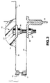
- One of the inner jacking points 16 is shown in more detail in Fig. 3.
- the bottom wall 18 of the air bar 12 is spaced from the arcuate peripheral wall 20 of the body 10.
- a jacking screw 22 is clamped by means of a lock nut 24 to a mounting plate 25 on the base wall 18 of the air bar 12 and is received in a nut 26 welded to a support flange 28 for the peripheral wall 20 of the body. After slackening nut 24 the jacking screw 22 can be turned until the desired spacing is obtained and then the lock nut 24 can be retightened.
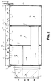
- Fig. 2 shows, by way of example, four jacking points 16, 17 which can be individually adjusted as just described.
- the air bars 12 can be given an individual curvature and for example can be bent to a convex shape which however is so slight as to be imperceptible in Fig. 2 of the drawings.
- the inner jacking points 16 can only be had when the web is removed and the air turn is shut down.
- the outside jacking points 17, which are constructed in substantially the same way as the jacking point 16 shown in Fig. 3, are accessible at all times and can be adjusted while the web is running.
- the longitudinal air discharge slots (not shown) of the air bars 12 are fed from the interior 30 of the air bars.
- the body 10 is divided into a number of zones or chambers 32, 34, 36 transversely to the path of web travel by means of interior partitions 38 and 40 as shown in Fig. 2.
- Individual openings 42 in the peripheral wall 20 place the chambers 32, 34 and 36 in communication with openings 43 of corresponding zones 33, 35, 37 of the air bars 12 and such zones in the air bars may likewise be separated from one another by partitions 44,46.
- four jacking points 16, 17 are suitable.
- the number of jacking points is increased if there are more than three air bar sections or in the case of very long air bars. Fewer jacking points can be used for shorter air bars.
- a duct 48 (Figs. 1 and 2) delivers air to the chamber 32, a duct 50 to the chamber 34 and a duct 52 to the chamber 36.
- the ducts 48, 50, 52 contain individually adjusted dampers 54.
- a common square section duct (not shown) communicates with the individual ducts 48, 50, 52 upstream of the dampers 54.
- the air supply can come from a fan (not shown) and the air may be heated.
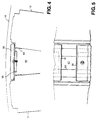
- the spent air discharged from the air bars flows to spaces 56 between the air bars 12 as shown diagrammatically in Fig. 4.
- the spaces 56 are partially closed off by means of adjustable baffles 58 which are clamped by mounting flats 59 to flanges of angle bars 60 attached to the air bars 12. Openings 62 are formed between the individual baffles 58 as shown in Fig. 5.
- the baffles 58 can be adjusted in number and can be moved axially along the air bars so that the openings 62 for the escape of spent air are adjusted. This enables the pressure between the web and the air bars to be regulated in order to create higher and lower pressure zones.
- the web to nozzle spacing can be adjusted transversely of the web by bending the air bars to a convex shape and/or by adjusting the air pressure longitudinally of the air bars and/or by adjusting the air pressures in the air cushions themselves.
Landscapes
- Engineering & Computer Science (AREA)
- Textile Engineering (AREA)
- Mechanical Engineering (AREA)
- General Engineering & Computer Science (AREA)
- Folding Of Thin Sheet-Like Materials, Special Discharging Devices, And Others (AREA)
Abstract
An air turn comprises air bars (12) supported on a body (10) at spaced points (16, 17) so that the air bars lie in an arcuate path to define a web travel path about the turn. The air bars (12) have Coanda nozzles to create a web-supporting air cushion. The supports at the jacking points (16, 17) are individually adjustable to enable the air bars (12) to be bent slightly to a convex arcuate shape as seen tangentially to the turn. Dampers (54) in inlets (48, 50, 52) control the air supply individually to zones (33, 35, 37) along the air bars. Baffles (58) regulate the air flow to exhaust zones (56) between the air bars to create higher and lower pressure zones supporting the web.
These measures each reduce the risk of the web creasing or folding.
Description
- The present invention relates to air turns.
- In a process line drying a continuous web it is often necessary to change the direction in which the web travels without the web making contact with a roller or curved guide. One method by which this is achieved is by the use of an air turn in which several air flotation nozzles are mounted around a circular chamber or around a portion of a circular chamber, around which the web is floated. The present invention relates to improvements to such a device in order to remove or eliminate creasing of the web, particularby where wide webs are being used. It is thought that such creasing is due to irregularities of the pressure differential across the web owing to a number of factors, such as mechanical imperfections and/or lack of flatness of the web.
- The air nozzle is usually in the form of a so-called air bar which is is an elongate box provided with a slit-like nozzle through which air is projected in order to maintain an air cushion for supporting the web.
- One aspect of the invention resides in an air turn having air nozzles mounted along an arcuate path or turn such that the nozzles are convex arcuate as seen tangentially to the web travel path defined by the air turn.
- Another aspect of the invention is an air turn having air nozzles mounted along an arcuate path by adjustable supports spaced apart transversely of the web travel path, enabling the nozzle profile to be adjusted. Thus, for example, the nozzles can be set with a convex arcuate configuration, as seen tangentially to the web travel path.
- A further aspect of the invention consists in an air turn having air nozzles mounted along an arcuate path and provided with several zones transversely of the web travel path defined by the air turn, and means enabling independent control of the air supply to each zone, thereby enabling different web-to-nozzle spacing to be established at different positions transversely of the web travel path.
- Yet another aspect of the invention is an air turn having air nozzles mounted along an arcuate path and spaced apart in the direction of the web travel path defined by the air turn, and means for regulating the air flow at exhaust zones formed between the nozzles to create higher and lower pressure zones providing the web support.
- The innvention is further described, by way of example, with reference to the accompanying drawings, in which:-
- Fig. 1 is an end elevational view of an air turn in accordance with the invention;
- Fig. 2 is a diagrammatic longitudinal section of the air turn;
- Fig. 3 is an enlarged sectional view of the detail marked III in Fig. 2;
- Fig. 4 is an enlarged sectional view of the detail marked IV in Fig. 1; and
- Fig. 5 is a plan view of the detail shown in Fig. 4.
- The drawings show an air turn designed for turning a web through approximately 180o without touching the web. The air turn comprises a
body 10 on which are mounted a series ofair bars 12 only some of which are shown in Fig. 1. - An air bar for float treatment apparatus is described in British Patent Specification No. 1,443,679. Such an air bar comprises an elongate pad plate whose opposite longitudinal edges are rounded and air discharge slots are provided alongside said rounded edges such that the discharged air flows over the rounded edges and on to the flat surface of the pad plate due to the Coanda effect, whereby to maintain a web-supporting air cushion on said pad plate. If the web is to be heated, e.g. to dry a surface coating thereon, the air to be discharged is heated.
- As can be seen in Fig. 1 the
air bars 12 extend transversely to the web travel path, theweb 14 being shown in Fig. 4. - The
air bars 12 are supported on thebody 10 at spacedjacking points inner jacking points 16 is shown in more detail in Fig. 3. Thebottom wall 18 of theair bar 12 is spaced from the arcuateperipheral wall 20 of thebody 10. Ajacking screw 22 is clamped by means of alock nut 24 to amounting plate 25 on thebase wall 18 of theair bar 12 and is received in anut 26 welded to asupport flange 28 for theperipheral wall 20 of the body. After slackeningnut 24 thejacking screw 22 can be turned until the desired spacing is obtained and then thelock nut 24 can be retightened. - Fig. 2 shows, by way of example, four
jacking points air bars 12 can be given an individual curvature and for example can be bent to a convex shape which however is so slight as to be imperceptible in Fig. 2 of the drawings. - Access to the
inner jacking points 16 can only be had when the web is removed and the air turn is shut down. However, theoutside jacking points 17, which are constructed in substantially the same way as thejacking point 16 shown in Fig. 3, are accessible at all times and can be adjusted while the web is running. - The longitudinal air discharge slots (not shown) of the
air bars 12 are fed from theinterior 30 of the air bars. Thebody 10 is divided into a number of zones orchambers interior partitions Individual openings 42 in theperipheral wall 20 place thechambers openings 43 ofcorresponding zones air bars 12 and such zones in the air bars may likewise be separated from one another bypartitions jacking points - As shown in Fig. 3, sealing arrangements 45 between the
air bars 12 and thebody wall 20 seal theopenings 42 to thecorresponding openings 43. A duct 48 (Figs. 1 and 2) delivers air to thechamber 32, aduct 50 to thechamber 34 and aduct 52 to thechamber 36. Theducts dampers 54. A common square section duct (not shown) communicates with theindividual ducts dampers 54. The air supply can come from a fan (not shown) and the air may be heated. By individual adjustment of thedampers 54, the pressure of the air supplied to individual zones of the air bars is adjusted. Such adjustment enables the height of the web above the air bars or rather the spacing of the web from the air bars to be varied at different positions transversely of theweb 14. - The spent air discharged from the air bars flows to
spaces 56 between theair bars 12 as shown diagrammatically in Fig. 4. Thespaces 56 are partially closed off by means ofadjustable baffles 58 which are clamped by mountingflats 59 to flanges ofangle bars 60 attached to theair bars 12.Openings 62 are formed between theindividual baffles 58 as shown in Fig. 5. Thebaffles 58 can be adjusted in number and can be moved axially along the air bars so that theopenings 62 for the escape of spent air are adjusted. This enables the pressure between the web and the air bars to be regulated in order to create higher and lower pressure zones. - By adopting one or more of the above measures adjustments can be made to compensate for non-uniformity or irregularities in the pressure differential across the web. That is to say, the web to nozzle spacing can be adjusted transversely of the web by bending the air bars to a convex shape and/or by adjusting the air pressure longitudinally of the air bars and/or by adjusting the air pressures in the air cushions themselves. By these measures, the risk of creasing or folding of the web, especially in the case of wide webs, e.g. up to 9 m wide, may be reduced.
Claims (10)
- An air turn having air nozzles (12) mounted along an arcuate path and provided with several zones (33,35,37) transversely of the web travel path defined by the air turn, and means (54) enabling independent control of the air supply to each zone (33,35,37), thereby enabling different web-to-nozzle spacing to be established at different positions transversely of the web travel path.
- An air turn as claimed in claim 1, in which the means to enable independent control comprise dampers (54) which are disposed in respective air ducts (48,50,52) leading to the respective zones (33,35,37) and are individually adjustable.
- An air turn as claimed in claim 1 or 2, further comprising means (58) for regulating the air flow at exhaust zones formed between the nozzles to create higher and lower pressure zones providing the web support.
- An air turn having air nozzles (12) mounted along an arcuate path and spaced apart in the direction of the web travel path defined by the air turn, and means for regulating the air flow at exhaust zones formed between the nozzles (12) to create higher and lower pressure zones providing the web support.
- An air turn as claimed in claim 4, in which the means for regulating comprise adjustable baffles (58) which are axially adjustable along the entries to the spaces (56) between the air nozzles (12) and are optimal in number.
- An air turn having air nozzles (12) mounted along an arcuate path or turn such that the nozzles (12) are convex arcuate as seen tangentially to the web travel path defined by the air turn.
- An air turn having air nozzles (12) mounted along an arcuate path by supports (16,17) spaced apart transversely of the web travel path, at least one of said supports being adjustable, enabling the nozzle profile to be adjusted.
- An air turn as claimed in claim 7, in which the or each adjustable support (16,17) comprises a jacking screw (22).
- An air turn as claimed in claim 7 or 8, in which the supports (16,17) include adjustable supports at the ends of the air nozzles (12) so as to be adjustable while the web is travelling around the air turn.
- An air turn as claimed in any of claims 3 to 9, in which the air nozzles (12) are provided with several zones (32,34,36) transversely of the web travel path and means are provided to enable independent control of the air supply to each zone.
Applications Claiming Priority (1)
| Application Number | Priority Date | Filing Date | Title |
|---|---|---|---|
| GB9012336A GB2245256A (en) | 1990-06-02 | 1990-06-02 | Pneumatic web guides |
Publications (1)
| Publication Number | Publication Date |
|---|---|
| EP0548419A1 true EP0548419A1 (en) | 1993-06-30 |
Family
ID=10676979
Family Applications (1)
| Application Number | Title | Priority Date | Filing Date |
|---|---|---|---|
| EP91311844A Withdrawn EP0548419A1 (en) | 1990-06-02 | 1991-12-20 | Improved air turn |
Country Status (2)
| Country | Link |
|---|---|
| EP (1) | EP0548419A1 (en) |
| GB (1) | GB2245256A (en) |
Cited By (5)
| Publication number | Priority date | Publication date | Assignee | Title |
|---|---|---|---|---|
| WO1995010473A1 (en) * | 1993-10-11 | 1995-04-20 | Krieger Gmbh & Co. Kg | Device for the suspension guidance of a travelling web |
| US5570519A (en) * | 1995-02-10 | 1996-11-05 | Valmet Corporation | Method and device in contact-free treatment of a web |
| EP1337798A4 (en) * | 2000-11-28 | 2009-01-14 | Megtec Sys Inc | Non-contact floating device for turning a floating web-private |
| EP3260802A1 (en) | 2016-06-23 | 2017-12-27 | Valmet Technologies Oy | Nozzle of a device for contact-free treatment of a running fiber web |
| CN113975577A (en) * | 2021-11-08 | 2022-01-28 | 李扬 | A therapeutic mask for pediatric immune system disorders |
Families Citing this family (2)
| Publication number | Priority date | Publication date | Assignee | Title |
|---|---|---|---|---|
| GB2245256A (en) * | 1990-06-02 | 1992-01-02 | Spooner Ind Ltd | Pneumatic web guides |
| DE10238765A1 (en) * | 2002-08-23 | 2004-03-04 | Voith Paper Patent Gmbh | Arrangement for contactless guiding and / or deflecting and / or handling a running material web, in particular made of paper or cardboard, and built-in module for building up such an arrangement |
Citations (9)
| Publication number | Priority date | Publication date | Assignee | Title |
|---|---|---|---|---|
| US2736106A (en) * | 1956-02-28 | Offen | ||
| GB894062A (en) * | 1957-07-20 | 1962-04-18 | J W Zanders Feinpapierfabrik G | Apparatus for guiding travelling webs such as paper webs |
| FR2201751A5 (en) * | 1972-10-02 | 1974-04-26 | Domtar Ltd | |
| DE2752574A1 (en) * | 1976-12-17 | 1978-06-22 | Bachofen & Meier Maschf | CONTROL DEVICE FOR GUIDING FLEXIBLE TRACKS, SUCH AS PAPER, CARDBOARD, PLASTIC FILM, TEXTILE TRACKS ETC. |
| EP0236819A2 (en) * | 1986-02-28 | 1987-09-16 | Thermo Electron-Web Systems, Inc. | Non-contact web turning and drying apparatus |
| US4837946A (en) * | 1988-03-09 | 1989-06-13 | Advance Systems, Inc. | Apparatus for floatingly suspending a running web through an arcuate path |
| DE3942029A1 (en) * | 1989-01-06 | 1990-07-12 | Valmet Paper Machinery Inc | DEVICE FOR CARRYING, REFLECTING AND SPREADING A TRAIN |
| GB2245256A (en) * | 1990-06-02 | 1992-01-02 | Spooner Ind Ltd | Pneumatic web guides |
| EP0482500A1 (en) * | 1990-10-23 | 1992-04-29 | Hoechst Aktiengesellschaft | Guiding device for guiding, deviating and/or reversing a web of material |
-
1990
- 1990-06-02 GB GB9012336A patent/GB2245256A/en not_active Withdrawn
-
1991
- 1991-12-20 EP EP91311844A patent/EP0548419A1/en not_active Withdrawn
Patent Citations (9)
| Publication number | Priority date | Publication date | Assignee | Title |
|---|---|---|---|---|
| US2736106A (en) * | 1956-02-28 | Offen | ||
| GB894062A (en) * | 1957-07-20 | 1962-04-18 | J W Zanders Feinpapierfabrik G | Apparatus for guiding travelling webs such as paper webs |
| FR2201751A5 (en) * | 1972-10-02 | 1974-04-26 | Domtar Ltd | |
| DE2752574A1 (en) * | 1976-12-17 | 1978-06-22 | Bachofen & Meier Maschf | CONTROL DEVICE FOR GUIDING FLEXIBLE TRACKS, SUCH AS PAPER, CARDBOARD, PLASTIC FILM, TEXTILE TRACKS ETC. |
| EP0236819A2 (en) * | 1986-02-28 | 1987-09-16 | Thermo Electron-Web Systems, Inc. | Non-contact web turning and drying apparatus |
| US4837946A (en) * | 1988-03-09 | 1989-06-13 | Advance Systems, Inc. | Apparatus for floatingly suspending a running web through an arcuate path |
| DE3942029A1 (en) * | 1989-01-06 | 1990-07-12 | Valmet Paper Machinery Inc | DEVICE FOR CARRYING, REFLECTING AND SPREADING A TRAIN |
| GB2245256A (en) * | 1990-06-02 | 1992-01-02 | Spooner Ind Ltd | Pneumatic web guides |
| EP0482500A1 (en) * | 1990-10-23 | 1992-04-29 | Hoechst Aktiengesellschaft | Guiding device for guiding, deviating and/or reversing a web of material |
Cited By (7)
| Publication number | Priority date | Publication date | Assignee | Title |
|---|---|---|---|---|
| WO1995010473A1 (en) * | 1993-10-11 | 1995-04-20 | Krieger Gmbh & Co. Kg | Device for the suspension guidance of a travelling web |
| US6502735B1 (en) | 1993-10-11 | 2003-01-07 | Kreiger Gmbh & Co. | Device for the suspension guidance of a travelling web |
| US5570519A (en) * | 1995-02-10 | 1996-11-05 | Valmet Corporation | Method and device in contact-free treatment of a web |
| EP1337798A4 (en) * | 2000-11-28 | 2009-01-14 | Megtec Sys Inc | Non-contact floating device for turning a floating web-private |
| EP3260802A1 (en) | 2016-06-23 | 2017-12-27 | Valmet Technologies Oy | Nozzle of a device for contact-free treatment of a running fiber web |
| CN113975577A (en) * | 2021-11-08 | 2022-01-28 | 李扬 | A therapeutic mask for pediatric immune system disorders |
| CN113975577B (en) * | 2021-11-08 | 2023-08-04 | 于亚楠 | A therapeutic face mask for pediatric immune system diseases |
Also Published As
| Publication number | Publication date |
|---|---|
| GB2245256A (en) | 1992-01-02 |
| GB9012336D0 (en) | 1990-07-25 |
Similar Documents
| Publication | Publication Date | Title |
|---|---|---|
| US4197972A (en) | Contactless turning guide having air slots longitudinally along running web edges | |
| US5395029A (en) | Flotation nozzle for web handling equipment | |
| US5156312A (en) | Flotation nozzle for web handling equipment | |
| US5209387A (en) | Gas film conveyor for elongated strips of web material | |
| US3052991A (en) | Apparatus for uniform accelerated drying of web material | |
| US4331510A (en) | Steam shower for improving paper moisture profile | |
| EP1337798B1 (en) | Non-contact floating device for turning a floating web-private | |
| EP0548419A1 (en) | Improved air turn | |
| WO1989002953A1 (en) | Arrangement of pressure nozzles for the treatment of webs | |
| EP1588112B1 (en) | Method and apparatus for adjusting a moisture profile in a web | |
| US4398355A (en) | Steam distribution apparatus | |
| US3599341A (en) | Method and apparatus for drying a web | |
| US3962799A (en) | Air bearing moisture profiler | |
| GB2132324A (en) | Apparatus for treatment of a web of material by gaseous medium | |
| GB2126974A (en) | Device for supporting a web on a bed of air | |
| US4249992A (en) | Steam shower for adjusting paper moisture profile | |
| JP2000511840A (en) | Blower nozzle | |
| US6502735B1 (en) | Device for the suspension guidance of a travelling web | |
| US3945570A (en) | Steam supply apparatus | |
| DE112011103033B4 (en) | Air bar arrangement for drying tissue paper on a belt | |
| US3577653A (en) | Web drying tunnel | |
| US4235667A (en) | Method of and means for attaining uniformity in paper webs produced on a roll former | |
| JP3212246U (en) | Equipment nozzle for non-contact processing of traveling fiber web | |
| GB1584770A (en) | Guide device for flexible webs | |
| JP2804810B2 (en) | Web supporting turning extension device |
Legal Events
| Date | Code | Title | Description |
|---|---|---|---|
| PUAI | Public reference made under article 153(3) epc to a published international application that has entered the european phase |
Free format text: ORIGINAL CODE: 0009012 |
|
| AK | Designated contracting states |
Kind code of ref document: A1 Designated state(s): CH DE ES LI |
|
| STAA | Information on the status of an ep patent application or granted ep patent |
Free format text: STATUS: THE APPLICATION IS DEEMED TO BE WITHDRAWN |
|
| 18D | Application deemed to be withdrawn |
Effective date: 19931231 |