EP3260714A1 - Stabilizer link - Google Patents
Stabilizer link Download PDFInfo
- Publication number
- EP3260714A1 EP3260714A1 EP16752272.1A EP16752272A EP3260714A1 EP 3260714 A1 EP3260714 A1 EP 3260714A1 EP 16752272 A EP16752272 A EP 16752272A EP 3260714 A1 EP3260714 A1 EP 3260714A1
- Authority
- EP
- European Patent Office
- Prior art keywords
- ball
- spherical
- stud
- ball seat
- stabilizer link
- Prior art date
- Legal status (The legal status is an assumption and is not a legal conclusion. Google has not performed a legal analysis and makes no representation as to the accuracy of the status listed.)
- Withdrawn
Links
- 239000003381 stabilizer Substances 0.000 title 1
Images










Classifications
-
- F—MECHANICAL ENGINEERING; LIGHTING; HEATING; WEAPONS; BLASTING
- F16—ENGINEERING ELEMENTS AND UNITS; GENERAL MEASURES FOR PRODUCING AND MAINTAINING EFFECTIVE FUNCTIONING OF MACHINES OR INSTALLATIONS; THERMAL INSULATION IN GENERAL
- F16C—SHAFTS; FLEXIBLE SHAFTS; ELEMENTS OR CRANKSHAFT MECHANISMS; ROTARY BODIES OTHER THAN GEARING ELEMENTS; BEARINGS
- F16C11/00—Pivots; Pivotal connections
- F16C11/04—Pivotal connections
- F16C11/06—Ball-joints; Other joints having more than one degree of angular freedom, i.e. universal joints
- F16C11/0619—Ball-joints; Other joints having more than one degree of angular freedom, i.e. universal joints the female part comprising a blind socket receiving the male part
- F16C11/0623—Construction or details of the socket member
- F16C11/0628—Construction or details of the socket member with linings
- F16C11/0633—Construction or details of the socket member with linings the linings being made of plastics
- F16C11/0638—Construction or details of the socket member with linings the linings being made of plastics characterised by geometrical details
-
- F—MECHANICAL ENGINEERING; LIGHTING; HEATING; WEAPONS; BLASTING
- F16—ENGINEERING ELEMENTS AND UNITS; GENERAL MEASURES FOR PRODUCING AND MAINTAINING EFFECTIVE FUNCTIONING OF MACHINES OR INSTALLATIONS; THERMAL INSULATION IN GENERAL
- F16C—SHAFTS; FLEXIBLE SHAFTS; ELEMENTS OR CRANKSHAFT MECHANISMS; ROTARY BODIES OTHER THAN GEARING ELEMENTS; BEARINGS
- F16C11/00—Pivots; Pivotal connections
- F16C11/04—Pivotal connections
- F16C11/06—Ball-joints; Other joints having more than one degree of angular freedom, i.e. universal joints
- F16C11/0619—Ball-joints; Other joints having more than one degree of angular freedom, i.e. universal joints the female part comprising a blind socket receiving the male part
- F16C11/0623—Construction or details of the socket member
- F16C11/0628—Construction or details of the socket member with linings
- F16C11/0633—Construction or details of the socket member with linings the linings being made of plastics
-
- B—PERFORMING OPERATIONS; TRANSPORTING
- B60—VEHICLES IN GENERAL
- B60G—VEHICLE SUSPENSION ARRANGEMENTS
- B60G21/00—Interconnection systems for two or more resiliently-suspended wheels, e.g. for stabilising a vehicle body with respect to acceleration, deceleration or centrifugal forces
- B60G21/02—Interconnection systems for two or more resiliently-suspended wheels, e.g. for stabilising a vehicle body with respect to acceleration, deceleration or centrifugal forces permanently interconnected
- B60G21/04—Interconnection systems for two or more resiliently-suspended wheels, e.g. for stabilising a vehicle body with respect to acceleration, deceleration or centrifugal forces permanently interconnected mechanically
- B60G21/05—Interconnection systems for two or more resiliently-suspended wheels, e.g. for stabilising a vehicle body with respect to acceleration, deceleration or centrifugal forces permanently interconnected mechanically between wheels on the same axle but on different sides of the vehicle, i.e. the left and right wheel suspensions being interconnected
- B60G21/055—Stabiliser bars
-
- B—PERFORMING OPERATIONS; TRANSPORTING
- B60—VEHICLES IN GENERAL
- B60G—VEHICLE SUSPENSION ARRANGEMENTS
- B60G21/00—Interconnection systems for two or more resiliently-suspended wheels, e.g. for stabilising a vehicle body with respect to acceleration, deceleration or centrifugal forces
- B60G21/02—Interconnection systems for two or more resiliently-suspended wheels, e.g. for stabilising a vehicle body with respect to acceleration, deceleration or centrifugal forces permanently interconnected
- B60G21/04—Interconnection systems for two or more resiliently-suspended wheels, e.g. for stabilising a vehicle body with respect to acceleration, deceleration or centrifugal forces permanently interconnected mechanically
- B60G21/05—Interconnection systems for two or more resiliently-suspended wheels, e.g. for stabilising a vehicle body with respect to acceleration, deceleration or centrifugal forces permanently interconnected mechanically between wheels on the same axle but on different sides of the vehicle, i.e. the left and right wheel suspensions being interconnected
- B60G21/055—Stabiliser bars
- B60G21/0551—Mounting means therefor
-
- F—MECHANICAL ENGINEERING; LIGHTING; HEATING; WEAPONS; BLASTING
- F16—ENGINEERING ELEMENTS AND UNITS; GENERAL MEASURES FOR PRODUCING AND MAINTAINING EFFECTIVE FUNCTIONING OF MACHINES OR INSTALLATIONS; THERMAL INSULATION IN GENERAL
- F16C—SHAFTS; FLEXIBLE SHAFTS; ELEMENTS OR CRANKSHAFT MECHANISMS; ROTARY BODIES OTHER THAN GEARING ELEMENTS; BEARINGS
- F16C11/00—Pivots; Pivotal connections
- F16C11/04—Pivotal connections
- F16C11/06—Ball-joints; Other joints having more than one degree of angular freedom, i.e. universal joints
- F16C11/0619—Ball-joints; Other joints having more than one degree of angular freedom, i.e. universal joints the female part comprising a blind socket receiving the male part
- F16C11/0623—Construction or details of the socket member
- F16C11/0647—Special features relating to adjustment for wear or play; Wear indicators
-
- F—MECHANICAL ENGINEERING; LIGHTING; HEATING; WEAPONS; BLASTING
- F16—ENGINEERING ELEMENTS AND UNITS; GENERAL MEASURES FOR PRODUCING AND MAINTAINING EFFECTIVE FUNCTIONING OF MACHINES OR INSTALLATIONS; THERMAL INSULATION IN GENERAL
- F16C—SHAFTS; FLEXIBLE SHAFTS; ELEMENTS OR CRANKSHAFT MECHANISMS; ROTARY BODIES OTHER THAN GEARING ELEMENTS; BEARINGS
- F16C11/00—Pivots; Pivotal connections
- F16C11/04—Pivotal connections
- F16C11/06—Ball-joints; Other joints having more than one degree of angular freedom, i.e. universal joints
- F16C11/0619—Ball-joints; Other joints having more than one degree of angular freedom, i.e. universal joints the female part comprising a blind socket receiving the male part
- F16C11/0623—Construction or details of the socket member
- F16C11/0657—Construction or details of the socket member the socket member being mainly made of plastics
-
- F—MECHANICAL ENGINEERING; LIGHTING; HEATING; WEAPONS; BLASTING
- F16—ENGINEERING ELEMENTS AND UNITS; GENERAL MEASURES FOR PRODUCING AND MAINTAINING EFFECTIVE FUNCTIONING OF MACHINES OR INSTALLATIONS; THERMAL INSULATION IN GENERAL
- F16C—SHAFTS; FLEXIBLE SHAFTS; ELEMENTS OR CRANKSHAFT MECHANISMS; ROTARY BODIES OTHER THAN GEARING ELEMENTS; BEARINGS
- F16C11/00—Pivots; Pivotal connections
- F16C11/04—Pivotal connections
- F16C11/06—Ball-joints; Other joints having more than one degree of angular freedom, i.e. universal joints
- F16C11/068—Special features relating to lubrication
-
- B—PERFORMING OPERATIONS; TRANSPORTING
- B60—VEHICLES IN GENERAL
- B60G—VEHICLE SUSPENSION ARRANGEMENTS
- B60G2204/00—Indexing codes related to suspensions per se or to auxiliary parts
- B60G2204/10—Mounting of suspension elements
- B60G2204/12—Mounting of springs or dampers
- B60G2204/122—Mounting of torsion springs
- B60G2204/1224—End mounts of stabiliser on wheel suspension
-
- B—PERFORMING OPERATIONS; TRANSPORTING
- B60—VEHICLES IN GENERAL
- B60G—VEHICLE SUSPENSION ARRANGEMENTS
- B60G2204/00—Indexing codes related to suspensions per se or to auxiliary parts
- B60G2204/40—Auxiliary suspension parts; Adjustment of suspensions
- B60G2204/416—Ball or spherical joints
-
- F—MECHANICAL ENGINEERING; LIGHTING; HEATING; WEAPONS; BLASTING
- F16—ENGINEERING ELEMENTS AND UNITS; GENERAL MEASURES FOR PRODUCING AND MAINTAINING EFFECTIVE FUNCTIONING OF MACHINES OR INSTALLATIONS; THERMAL INSULATION IN GENERAL
- F16C—SHAFTS; FLEXIBLE SHAFTS; ELEMENTS OR CRANKSHAFT MECHANISMS; ROTARY BODIES OTHER THAN GEARING ELEMENTS; BEARINGS
- F16C2208/00—Plastics; Synthetic resins, e.g. rubbers
- F16C2208/20—Thermoplastic resins
- F16C2208/60—Polyamides [PA]
-
- F—MECHANICAL ENGINEERING; LIGHTING; HEATING; WEAPONS; BLASTING
- F16—ENGINEERING ELEMENTS AND UNITS; GENERAL MEASURES FOR PRODUCING AND MAINTAINING EFFECTIVE FUNCTIONING OF MACHINES OR INSTALLATIONS; THERMAL INSULATION IN GENERAL
- F16C—SHAFTS; FLEXIBLE SHAFTS; ELEMENTS OR CRANKSHAFT MECHANISMS; ROTARY BODIES OTHER THAN GEARING ELEMENTS; BEARINGS
- F16C2208/00—Plastics; Synthetic resins, e.g. rubbers
- F16C2208/20—Thermoplastic resins
- F16C2208/66—Acetals, e.g. polyoxymethylene [POM]
-
- F—MECHANICAL ENGINEERING; LIGHTING; HEATING; WEAPONS; BLASTING
- F16—ENGINEERING ELEMENTS AND UNITS; GENERAL MEASURES FOR PRODUCING AND MAINTAINING EFFECTIVE FUNCTIONING OF MACHINES OR INSTALLATIONS; THERMAL INSULATION IN GENERAL
- F16C—SHAFTS; FLEXIBLE SHAFTS; ELEMENTS OR CRANKSHAFT MECHANISMS; ROTARY BODIES OTHER THAN GEARING ELEMENTS; BEARINGS
- F16C2220/00—Shaping
- F16C2220/02—Shaping by casting
- F16C2220/04—Shaping by casting by injection-moulding
-
- F—MECHANICAL ENGINEERING; LIGHTING; HEATING; WEAPONS; BLASTING
- F16—ENGINEERING ELEMENTS AND UNITS; GENERAL MEASURES FOR PRODUCING AND MAINTAINING EFFECTIVE FUNCTIONING OF MACHINES OR INSTALLATIONS; THERMAL INSULATION IN GENERAL
- F16C—SHAFTS; FLEXIBLE SHAFTS; ELEMENTS OR CRANKSHAFT MECHANISMS; ROTARY BODIES OTHER THAN GEARING ELEMENTS; BEARINGS
- F16C2326/00—Articles relating to transporting
- F16C2326/01—Parts of vehicles in general
- F16C2326/05—Vehicle suspensions, e.g. bearings, pivots or connecting rods used therein
Definitions
- the present invention relates to a stabilizer link to be connected with a suspension of a vehicle.
- a vehicle conventionally includes a suspension and a stabilizer, as disclosed in Patent Document 1.
- the suspension includes an oil damper and a compression coil spring to reduce the impact transmitted from the road surface to the vehicle body.
- the stabilizer uses a restoring force caused by torsional deformation of a bar to increase roll stiffness (rigidity against torsion) of the vehicle body.
- the suspension and the stabilizer are connected with each other via a stabilizer link.
- the stabilizer link is formed to have one connecting part to be fixed to the suspension and the other connecting part to be fixed to the stabilizer, which are arranged at both ends of a solid or hollow support bar.
- Each of the connecting parts arranged at both ends of the support bar has a ball joint structure to include a ball stud and a housing for accommodating the ball stud.
- the housings of the connecting parts are integrally attached to both ends of the support bar.
- the housing is a member in a cup shape to accommodate a sphere part (ball part) of the ball stud so as to be slidable.
- the housing includes therein a resin supporting member (ball seat). The ball part of the ball stud is received by the ball seat so as to be slidable.
- the ball part is slidable on the inner surface of the ball seat to allow the ball stud to be swingable and rotatable.
- the stabilizer link has a ball joint structure as described above in each of the connecting parts at both ends, to movably connect the suspension with the stabilizer.
- the frictional force between the ball part and the ball seat is preferably maintained at a low value as designed.
- the ball seat receiving the ball part is made of resin. Accordingly, the size largely varies at the time of molding to make it difficult for the frictional force between the ball part and the ball seat to be maintained.
- Patent Document 1 Japanese Patent Application Publication No. 2011-247338
- Characteristics of movement between the suspension and the stabilizer affect steering stability of a vehicle, smoothness of the steering, ride quality, and the like. For example, if the torque of the ball stud swinging and rotating is large, the suspension and the stabilizer stiffly operate with each other to have problems such as lack of smoothness in operation and degradation of ride quality. Also, if the interference between the ball part and the ball seat is small, the ball part and the ball seat have reduced friction accordingly but suffer from loosening (elastic lift) therebetween. Such loosening causes noise and instability of ride quality, and therefore deteriorates the vehicle quality.
- the stabilizer link is a part having a ball joint structure that connects the stabilizer with a strut, an arm, and the like. As the suspension of the vehicle strokes, the stabilizer link is swung and rotated, and these characteristics are defined as swinging torque and rotating torque.
- the stabilizer link as a suspension part is required to have its swinging and rotating torque reduced. Decreasing the interference between the ball seat and the housing leads to reducing the torque but at the same time causes the elastic lift to be increased.
- the ball seat is a resin part and is manufactured by injection molding.
- the wall of the ball seat is formed to be thicker downward and thinner upward in the axial direction of the ball stud, and then the ball seat is not formed to have a constant outer radius due to the influence of heat shrinkage during molding, to have a tapered shape of being narrower downward and being wider upward. That is, a flange portion is formed in such a shape that the opening side of the main body extends peripherally outward.
- the housing into which the ball seat is fitted is formed to have the inner radius being vertically straight in the axial direction of the ball stud, and therefore the ball seat and the housing contact less with each other as the interference therebetween is decreased, to have elastic lift increased.
- the ball joint part may suffer from loosening to have abnormal noise while the vehicle is traveling. This loosening deteriorates accurate dynamic characteristics of the stabilizer link system.
- the elastic lift accelerates wearing of mutual parts to further increase the occurrence of abnormal noise and inaccurate dynamic characteristics of the stabilizer link system. As the elastic lift increases inversely with torque reduction, there is a limit to the torque reduction of the ball stud.
- the present invention has been devised in view of the above circumstances, and is intended to provide a stabilizer link that effectively suppresses loosening between a spherical part of a ball stud and a support member, which is arranged in a housing to receive the spherical portion so as to be slidable, and allows torque of the ball stud swinging and rotating to be reduced.
- a stabilizer link includes: an arm part; and connecting parts that are arranged at both ends of the arm part, wherein one of the connecting parts is connected to a first structure and the other of the connecting parts is connected to a second structure, and at least one of the connecting parts has a ball joint structure
- the connecting part having the ball joint structure includes: a housing that supports a ball stud to be connected to the first or second structure so as to be swingable and rotatable, the ball stud having a spherical part and a stud part extending from the spherical part; and a support member that receives the spherical part in a spherical space so as to be slidable for the housing to support the ball stud, and includes: an opening where the spherical space is open for the stud part extending therethrough; a lubricant receiving part in a concave shape that is formed at a bottom
- the wall surface of the support member forms the spherical space for the spherical part to slide thereon and has the recessed grooves formed circumferentially about the central axis of the spherical space running from the opening to the lubricant receiving part, on both sides or one side in the central axis direction of the portion of the wall surface having the maximum inner radius about the central axis, to allow the ball stud to be well supported yet to have reduced torque.
- a second aspect of the present invention is the stabilizer link according to the first aspect of the present invention, wherein the recessed grooves are formed in zones of the wall surface where the torque required for sliding the spherical part in the spherical space is larger than that in the other zones except an end of the wall surface.
- the recessed grooves are formed in zones of the wall surface where the torque required for sliding the spherical part in the spherical space is larger than that in the other zones except the end of the wall surface, to allow the ball stud to have reduced torque even if a recessed groove is formed in a narrow zone.
- the recessed groove may occupy a relatively narrow zone for reliably supporting the ball stud.
- a third aspect of the present invention is the stabilizer link according to the first or second aspect of the present invention, wherein the size of the recessed groove is determined so that the torque required for sliding the spherical part in the spherical space is 0.5 Nm or less.
- the size of the recessed groove is determined so that the torque required for sliding the spherical part in the spherical space is 0.5 Nm or less, to allow the ball stud to have reduced torque as desired.
- a stabilizer link includes: an arm part; and connecting parts that are arranged at both ends of the arm part, wherein one of the connecting parts is connected to a first structure and the other of the connecting parts is connected to a second structure, and at least one of the connecting parts has a ball joint structure
- the connecting part having the ball joint structure includes: a housing that supports a ball stud to be connected to the first or second structure so as to be swingable and rotatable, wherein the ball stud has a spherical part and a stud part extending from the spherical part; and a support member that receives the spherical part in a spherical space so as to be slidable for the housing to support the ball stud, and includes: an opening where the spherical space is open for the stud part extending therethrough; a lubricant receiving part in a concave shape that is formed at a bottom opposed to the opening; and a wall surface that forms
- the wall surface of the support member forms the spherical space for the spherical part to slide thereon and has the recessed groove formed circumferentially about the central axis of the spherical space running from the opening to the lubricant receiving part, in the vicinity of the portion of the wall surface having the maximum inner radius about the central axis, wherein the size of the recessed groove is determined so that the torque required for sliding the spherical part in the spherical space is 0.5 Nm or less, to allow the ball stud to have the swinging torque and the rotating torque reduced as desired.
- a fifth aspect of the present invention is the stabilizer link according to any one of the first, second, and fourth aspects of the present invention, wherein a zone of the wall surface forming the spherical space, on which the spherical part slides, occupies 38.5 % or more of a zone of the same defined by top and bottom circumferences of the spherical space in correspondence with a central angle of 63 to 75 degrees.
- the zone of the wall surface forming the spherical space, on which the spherical part slides occupies 38.5 % or more of the zone of the same defined by top and bottom circumferences of the spherical space in correspondence with a central angle of 63 to 75 degrees, to allow the ball stud to be reliably supported.
- a sixth aspect of the present invention is the stabilizer link according to any one of the first, second, and fourth aspects of the present invention, wherein the distance between an edge of the spherical space, on which the spherical part slides, and the outmost recessed groove is 0.5 mm or more.
- the support member reliably supports the spherical part of the ball stud.
- the support member forming the spherical space is inhibited from chipping.
- a seventh aspect of the present invention is the stabilizer link according to any one of the first, second, and fourth aspects of the present invention, wherein an end of the recessed groove continues to the wall surface in the spherical space at an angle of 50 degrees or more to a normal line to the wall surface.
- the end of the recessed groove continues to the wall surface in the spherical space at an angle of 50 degrees or more to a normal line to the wall surface, to falicitate removing the die at the time of forming the support member.
- An eighth aspect of the present invention is the stabilizer link according to any one of the first, second, and fourth aspects of the present invention, wherein the depth of the recessed groove is 0.08 mm to 0.25 mm.
- the depth of the recessed groove is 0.08 mm to 0.25 mm, to avoid the recessed groove from impairing its function when the support member is deformed. In addition, the strength of the support member is ensured.
- a ninth aspect of the present invention is the stabilizer link according to any one of the first, second, and fourth aspects of the present invention, wherein an upper end of the spherical part in a direction of the axis of the stud part is exposed on the outside of the spherical space.
- the upper end of the spherical part in the direction of the axis of the stud part is exposed on the outside of the spherical space, to allow the ball stud to be smoothly operated.
- a tenth aspect of the present invention is the stabilizer link according to any one of the first, second, and fourth aspects of the present invention, wherein the support member is made of a thermoplastic resin and is injection molded to form the recessed groove.
- the support member is made of a thermoplastic resin and is injection molded to form the recessed groove, to facilitate forming the recessed groove.
- the present invention provides a stabilizer link that effectively suppresses loosening between the spherical part of the ball stud and the support member, which is accommodated in the housing to receive the spherical part so as to be slidable, to cause the torque of the ball stud swinging and rotating to be reduced.
- FIG. 1 is a perspective view of a stabilizer link according to an embodiment of the present invention connecting a suspension damper with a stabilizer.
- a wheel W used for a vehicle (not shown) travelling is attached to a vehicle body (not shown) via a suspension 3.
- the suspension 3 includes a coil spring 3a and a suspension damper 3b.
- the suspension damper 3b rotatably supports the wheel W.
- the suspension damper 3b and the coil spring 3a damp the impact applied to the vehicle body from the wheel W.
- the suspension damper 3b is attached to the vehicle body (not shown) via the coil spring 3a.
- the viscous damping force of the suspension damper 3b at the time of expansion and contraction and the elastic force of the coil spring 3a are used to damp vibration transmitted to the vehicle body by the suspension 3.
- a stabilizer 2 is connected between the right and left suspensions 3.
- the stabilizer 2 increases the roll rigidity (rigidity against torsion) of the vehicle body to prevent the vehicle from rolling.
- the stabilizer 2 has a torsion bar 2a and a pair of arm parts 2b extending in a U-shape from both ends of the torsion bar 2a.
- the stabilizer 2 is formed with a rod-shaped spring member which is appropriately bent according to the shape of the vehicle.
- the stabilizer 2 connects the two suspension dampers 3b, respectively supporting the two opposed wheels W, with each other via a stabilizer link 1 of the present embodiment.
- One end of one arm part 2b of the stabilizer 2 continues to one end of the torsion bar 2a, while the other end of one arm part 2b is connected to one connection part 1b of the stabilizer link 1 .
- the other connecting part 1b of the stabilizer link 1 is connected to the suspension damper 3b.
- one end of the other arm part 2b of the stabilizer 2 continues to the other end of the torsion bar 2a, while the other end of the other arm part 2b is connected to one connection part 1b of the stabilizer link 1 .
- the other connecting part 1b of the stabilizer link 1 is connected to the suspension damper 3b.
- the torsion bar 2a extends from one suspension damper 3b toward the other suspension damper 3b.
- the arm parts 2b are shifted, such as when the vehicle turns, via the stabilizer link 1 due to the difference in expansion and contraction amount between the two suspension dampers 3b to twist the torsion bar 2a.
- the torsion bar 2a suppresses the rolling of the vehicle by the torsional elastic force acting to restore the torsion.
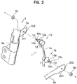
- FIG. 2 is an exploded perspective view of disassembled area I in FIG. 1 .
- the stabilizer link 1 is formed to include a rod-like support bar 1a and a connecting part 1b. Two connecting parts 1b are arranged at both ends of the support bar 1a.
- the support bar 1a is, for example, a rod-shaped member made of solid steel bar.
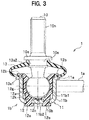
- FIG. 3 is a longitudinal sectional view of a connecting part of the stabilizer link.
- a ball stud 10 is supported so as to be swingable and rotatable.
- the ball stud 10 is accommodated in a housing 11 of the connecting part 1b.
- the connecting part 1b includes a dust boot 13 for preventing foreign matter from entering into the housing 11.
- the ball stud 10 supported by one connecting part 1b is fastened and fixed to a bracket 3c of the suspension damper 3b (see FIG. 2 ).
- the ball stud 10 provided in the other connecting part 1b is fastened and fixed to the arm part 2b of the stabilizer 2.
- the bracket 3c is attached to the suspension damper 3b by spot welding or the like.
- the bracket 3c has a flat part for fixing that extends so as to face the arm part 2b of the stabilizer 2 (on the center side of the vehicle not shown).
- a flat part 3c1 of the bracket 3c has a mounting hole 3c2 opened.
- the ball stud 10 has a flange part 10a, which peripherally extends, formed on a stud part 10s.
- a male screw 10n is threaded on a distal end of the stud 10s beyond the flange part 10a.
- one ball stud 10 has the stud part 10s inserted into the mounting hole 3c2 of the bracket 3c up to the flange part 10a which peripherally extends. Then, a nut N1 is screwed onto the male screw 10n threaded on the stud part 10s of the ball stud 10 which has been inserted through the mounting hole 3c2, to fix the ball stud 10 to the suspension damper 3b.
- the stabilizer link 1 has the arm part 2b plastically deformed into a flat shape in the vicinity of a distal end 2b1 so as to have an attachment hole 2b2 penetrated.
- the arm part 2b of the stabilizer link 1 has the distal end 2b1 and its vicinity plastically deformed into a flat face so as to face the suspension damper 3b, and has the attachment hole 2b2 opened in the distal end 2b1.
- the other ball stud 10 has the stud part 10s inserted into the mounting hole 2b2 of the arm part 2b of the stabilizer 2 upto the flange part 10a. Then, a nut N2 is screwed onto the male screw 10n threaded on the stud part 10s of the ball stud 10 which has been inserted through the mounting hole 2b2, to fix the ball stud 10 to the arm part 2b of the stabilizer 2.
- the stabilizer link 1 is fixed to the suspension damper 3b and the arm part 2b of the stabilizer 2 via the ball studs 10 arranged at both ends of the support bar 1a.
- the ball stud 10 is supported by the connecting part 1b of the stabilizer link 1 so as to be swingable and rotatable. Accordingly, the stabilizer link 1 is movable with respect to the suspension damper 3b and the torsion bar 2a.
- the stabilizer link 1 is a member to be connected to the stabilizer 2 and the suspension 3.
- the stabilizer link 1 has the connecting parts 1b arranged at both ends of the support bar 1a.
- the connecting part 1b includes the housing 11 in a cup shape for accommodating a ball part 10b of the ball stud 10.
- the housing 11 is attached to each end of the support bar 1a by resistance welding or the like.
- the housing 11 is made of a steel material such as carbon steel for machine structural use and houses therein a ball seat 12 made of resin as a support member.
- the ball stud 10 includes the ball part 10b in a substantially spherical shape and the stud part 10s unidirectionally extending from the ball part 10b.
- the ball stud 10 is received in the ball seat 12 of the connecting part 1b at the ball part 10b.
- the ball part 10b of the ball stud 10 is formed in a true sphere or a shape close to a true sphere.
- the upper part of the ball part 10b continues to the stud part 10s, while the lower part of the ball part 10b is geometrically restricted in order to secure volume of a grease chamber 12c.
- the ball part 10b of the ball stud 10 is formed in a true sphere or a shape close to a true sphere within an allowance.
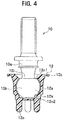
- FIG. 4 is a longitudinal sectional view of the ball seat 12 having the ball part of the ball stud 10 fitted therein.
- the ball seat 12 is formed of resin by injection molding.
- the ball seat 12 is made of a thermoplastic resin such as POM (Polyacetal), PA6 (Polyamide 6), and PA66 (Polyamide 66).
- the ball seat 12 is formed into a tapered shape in which the outer radius of a flange part 12b is larger than that of a main body 12a due to molding shrinkage.
- the ball seat 12 is made of resin and includes the main body 12a and the flange part 12b.
- the main body 12a is accommodated in the housing 11 (see FIG. 3 ).
- the main body 12a of the ball seat 12 has a cup shape in which the ball part 10b of the ball stud 10 is tightly fitted.
- the main body 12a of the resin ball seat 12 is fixed into the housing 11 by hot pressure welding. That is, the main body 12a is formed with bosses 12o for fixing. The bosses 12o which have penetrated holes in the bottom of the housing 11 are melted to fix the ball seat 12 in the housing 11. The bosses 12o are pressed and welded in a heated state.
- the main body 12a of the ball seat 12 encloses a spherical space 12k in a spherical shape. Then, the ball part 10b of the ball stud 10 is received in the spherical space 12k so as to be slidable. In addition, the stud part 10s of the ball stud 10, which is integrally formed with the ball part 10b, is moved together with the ball part 10b. At this time, the stud part 10s has sliding torque applied thereto due to the sliding in the spherical space 12k of the ball part 10b. Therefore, the ball stud 10 received in the ball seat 12 has the stud part 10s to be swingable and/or rotatable in accordance with the sliding of the ball part 10b.
- the housing 11 supports the ball stud 10 so as to be swingable and/or rotatable.
- the connecting part 1b includes the ball stud 10 having the stud part 10s and the ball part 10b so as to be swingable and rotatable, to form a ball joint structure.
- swinging torque is applied to the stud part 10s when the stud part 10s swings
- rotating torque is applied to the stud part 10s when the stud part 10s rotates. That is, each of the swinging torque and the rotating torque is an aspect of the sliding torque.
- the ball part 10b is arranged to have its upper end in the axial direction of the stud part 10s exposed on the outside of the spherical space. Note that the extending direction of the stud part 10s in the stabilizer link 1 is suitably determined according to the positional relationship between the suspension damper 3b (see FIG. 2 ) and the arm part 2b of the stabilizer 2.
- the housing 11 includes a flange part 11a and a main body 11b in a cup shape.
- the flange part 11a is formed so as to peripherally extend at an opening of the housing 11.
- the flange part 11a of the housing 11 and the flange part 12b of the ball seat 12 face each other.
- the end side of the dust boot 13 is held between the flange parts 11a, 12b which face each other.
- the dust boot 13 is a hollow member made of an elastic body such as rubber.
- the dust boot 13 prevents foreign matter (dirt or the like) from entering into the housing 11 or the ball seat 12.
- the dust boot 13 is arranged around the ball stud 10 between the flange part 10a thereof and the flange part 11a of the housing 11.
- the dust boot 13 has two openings 13a1, 13a2 at positions facing each other.
- One opening 13a1 is formed to peripherally bend inward, and this portion is held between the flange parts 11a, 12b which face each other.
- the other opening 13a2 of the dust boot 13 is closely contacted with, and fixed to, the stud part 10s of the ball stud 10.
- the dust boot 13 is shaped so as not to inhibit the stud part 10s from swinging and rotating.
- the dust boot 13 preferably has a shape that largely bulges outward. Having a shape that largely bulges outward allows the dust boot 13 to cover the stud part 10s with a deformation allowance. As a result, the dust boot 13 is easily deformed in accordance with the stud part 10s swinging and/or rotating. This allows the ball stud 10 to smoothly swing and rotate without being inhibited by the dust boot 13.
- FIG. 5 is a chart showing the correlation between the radius of an inner surface 11b1 (see FIG. 3 ) of the main body 11b of the housing 11 and the outer radius of the ball seat 12.
- the horizontal axis in FIG. 5 indicates the radius, and the vertical axis in FIG. 5 indicates the height from a bottom surface 11b2 of the housing 11.
- the solid line indicates the position of the inner surface 11b1 of the main body 11b of the housing 11
- the broken line indicates the outer radius of a conventional ball seat having a large interference between the inner surface 11b1 of the main body 11b of the housing 11 and an outer surface 12g of the ball seat 12
- the bold solid line indicates the outer radius of the low-torque ball seat 12 having a small interference between the inner surface 11b1 of the main body 11b of the housing 11 and the outer surface 12g (see FIG. 3 ) of the ball seat 12.
- the inner surface 11b1 of the main body 11b of the housing 11 is vertically straight to have an identical radius (inner radius), the inner surface 11b1 of the housing 11 and the outer surface of the ball seat contact less with each other as the interference therebetween is reduced.
- the interference between the inner surface 11b1 of the main body 11b of the housing 11 and the outer surface 12g of the ball seat 12 is increased (broken line in FIG. 5 ), the inner surface 11b1 of the housing 11 and the outer surface of the ball seat contact more with each other, that is, improved, but the rate of the ball seat 12 being pressed inward increases so that the torque at the time of the ball stud 10 swinging increases.
- FIG. 6 is a chart showing the correlation between the interference between the outer surface of the ball seat 12 and the inner surface of the main body of the housing, and the swinging torque of the ball stud.
- the horizontal axis indicates the interference between the outer surface 12g of the ball seat 12 and the inner surface 11b1 of the main body 11b of the housing 11, and the vertical axis indicates the swinging torque of the ball stud 10.
- the swinging torque of the ball stud 10 decreases as the interference between the outer surface 12g of the ball seat 12 and the inner surface 11b1 of the main body 11b of the housing 11 decreases.
- FIG. 7 is a chart showing the correlation between the interference, between the outer surface of the ball seat and the inner surface of the main body of the housing, and the elastic lift.
- the elastic lift that is, the elastic lift (loosening) of the ball seat 12 with respect to the inner surface 11b1 of the main body 11b of the housing 11 increases.
- FIGS. 8A and 8B are charts showing the presence or absence of an elastic lift before and after a durability test.
- FIG. 8A shows the correlation, before the durability test, between the deflection of the outer surface of the ball seat and the load
- FIG. 8B shows the correlation, after the durability test, between the deflection of the outer surface of the ball seat and the load.
- the horizontal axis indicates the deflection amount of the outer surface 12g of the ball seat 12
- the vertical axis indicates the load.
- FIGS. 8A and 8B indicate the cases where the interference between the inner surface 11b1 of the main body 11b of the housing 11 and the outer surface 12g of the ball seat 12 is normal, that is, the swinging and rotating torque of the ball stud 10 is normal.
- the solid lines in FIGS. 8A and 8B indicate the cases where the interference between the inner surface 11b1 of the main body 11b of the housing 11 and the outer surface 12g of the ball seat 12 is small, that is, the swinging and rotating torque of the ball stud 10 is small.
- the deflection is "0" when the load is set to "0" in both of the cases of the normal torque (broken line) and the small torque (solid line), to have no hysteresis observed.
- the interference is small in the case of the small torque, while the interference is large in the case of the normal torque. Accordingly, when a load is applied, the interference is small in the case of the small torque to have large amount of deflection, while the interference is large in the case of the normal torque to have small amount of deflection.
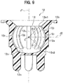
- FIG. 9 is a longitudinal sectional view of the ball seat having the grease groove formed to show the internal structure thereof.
- the ball seat 12 has eight grease grooves 12r formed in the direction of the axis J1 of the ball seat 12 for retaining grease therein.
- the grease groove 12r has a width of about 2 mm.
- the ball seat 12 has an opening 12i defined inside at the top thereof for the ball stud 10 swinging and rotating.
- a ray extending from the central point of the ball seat 12 through the edge of the opening 12i is at an angle ⁇ 0 of about 23 to about 30 degrees to a center line J2 extending horizontally through the central point.
- the ball seat 12 has the grease chamber 12c arranged inside at the bottom thereof.
- a ray extending from the central point of the ball seat 12 through the edge of the grease chamber 12c is at an angle ⁇ 1 of about 40 to about 45 degrees to the ray J2.
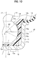
- FIG. 10 is a cross-sectional view of the connecting part of the stabilizer link with the ball stud in an equilibrium state (setup state) to show the internal structure thereof.
- FIG. 11 is a cross-sectional view of the connecting part of the stabilizer link with the ball stud swinging to show the internal structure thereof.
- FIGS. 10 and 11 cross sections of the housing 11, the ball seat 12, and the dust boot 13 are shown.
- the ball part 10b of the ball stud 10 receives a surface pressure as indicated by arrows from the contacting inner surface 12n of the ball seat 12.
- the frictional force between the ball part 10b of the ball stud 10 and the contacting inner surface 12n of the ball seat 12 due to sliding action is the frictional force when the ball stud 10 swings and rotates as shown in FIG. 11 , with respect to the stabilizer link 1. Therefore, this frictional force is the swinging and rotating torque when the ball stud 10 swings and rotates. In other words, the sliding torque caused by the frictional force results in the swinging and rotating torque.
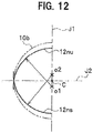
- FIG. 12 is a conceptual diagram showing the center offset of the inner surface of the ball seat.
- the upper inner surface 12nu closer to the opening has the central point O1 on the lower side
- the lower inner surface 12ns closer to the opposite side of the opening has the central point O2 on the upper side.
- the inner surface 12n of the ball seat 12 is formed to have a higher surface pressure at an end portion (a portion of the ball seat 12 closer to the opening or the opposite side of the opening) than at the equator (a portion of the ball seat 12 having the maximum radius about the axis J1 which runs through the centers of the opening 12i (see FIG. 10 ) and the grease chamber 12c (see FIG. 10 ) on its opposite side).
- the center offset in FIG. 12 allows the upper and lower end portions of the ball seat 12 to have the maximum surface pressure distributed thereat.
- the surface pressure to the ball part 10b caused by the interference above the equator generates a reaction force on the lower part of the ball seat 12 due to balancing of the static force, so that the ball seat 12 has surface pressure distribution of having the maximum surface pressure at the two circles, top and bottom, i.e., the edge 12nl at the opening 12i (see FIG. 9 ) and the edge 12n2 to the grease chamber (see FIG. 9 ), to determine the ball position.
- FIG. 13 is a chart showing the correlation between the percentage of contact between the ball part of the ball stud and the inner surface of the ball seat, and the swinging torque and elastic lift when the ball stud swings.
- the horizontal axis indicates the percentage of contact between the ball part 10b of the ball stud 10 and the inner surface 12n of the ball seat 12, and the vertical axis indicates the magnitudes of the swinging torque and elastic lift. Note that the percentage of 100% on the horizontal axis means that there is no gap (inclusive of the grease groove 12r) in the zone where the inner surface 12n of the ball seat 12 contacts the ball part 10b, as shown in FIG. 10 .
- FIG. 14 is a schematic diagram showing the equator, circle of longitude, and circle of latitude of the ball part of the ball stud.
- the equator of the ball part 10b of the ball stud 10 means a circumferential portion thereof connecting spots having the longest radius about the vertical axis direction of the stud part 10s of the spherical ball part 10b.
- the circle of longitude of the ball part 10b is a circumferential line perpendicular to the equator of the ball part 10b and corresponds to the circle of longitude set for the earth.
- the circle of latitude of the ball part 10b is a circumferential line parallel to the equator of the ball part 10b and corresponds to the circle of latitude set for the earth.
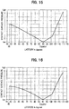
- FIG. 15 is a chart showing the contact surface pressure per unit longitude by the angle from the equator, when the ball seat gaplessly contacts the ball part of the ball stud shown in FIG. 11 .
- the horizontal axis in FIG. 15 indicates the latitude having 90 degrees at the equator, and decreasing with the increasing distance from the equator toward 0 degree at the center of the opening 12i, to have 48 degrees at the contacting point with the upper end of the ball seat 12.
- the angle increases with the increasing distance from the center of the opening 12i to have 115 degrees at the contacting point with the lower end of the ball seat 12.
- the vertical axis in FIG. 15 indicates the level of the surface pressure.
- the contact surface pressure per unit longitude was substantially "0" at the equator.
- the surface pressure increased substantially in a linear manner with the increasing distance from the equator toward the stud part 10s, while it increased similarly with the increasing distance from the stud part 10s in a range from the equator to 100 degrees and some, and then increased sharply after the latitude exceeding 100 degrees and some.
- FIG. 16 is a chart showing the contact surface pressure per unit latitude by the angle from the equator, when the ball seat gaplessly contacts the ball part of the ball stud in FIG. 10 , by integrating (adding) the pressure for each latitude.
- the horizontal axis in FIG. 16 indicates the latitude having 90 degrees at the equator, and decreasing with the increasing distance from the equator toward 0 degree at the center of the opening 12i, to have 48 degrees at the contacting point with the upper end (edge 12nl in FIG. 9 ) of the ball seat 12.
- the angle increases with the increasing distance from the center of the opening 12i to have 115 degrees at the contacting point with the lower end (edge 12n2 in FIG. 9 ) of the ball seat 12.
- the vertical axis in FIG. 16 indicates the level of the surface pressure.
- the integrated value of the surface pressure per unit latitude was substantially "0" at the latitude of the equator.
- the value increased substantially in a quadratic curve with the increasing distance from the equator toward the stud part 10s, while it increased similarly with the increasing distance from the stud part 10s in a range from the equator to 100 degrees and some, and then increased sharply after the latitude exceeding 100 degrees and some.
- Frictional force Surface pressure ⁇ Friction coefficient
- FIG. 17 is a chart qualitatively showing the rotating and swinging torque of the ball part of the ball stud shown in FIG. 14 at each latitude.
- the horizontal axis indicates the latitude of the ball part 10b of the ball stud 10 in FIG. 14
- the vertical axis indicates the level of the torque.
- the swinging torque at a time of the stud part 10s of the ball stud 10 swinging is expressed by the product of the surface pressure and the radius "r" (see FIG. 14 ) of the ball part 10b.
- the rotating torque at a time of the ball stud 10 rotating about the axis J1 (see FIG. 14 ) of the stud part 10s is expressed by a value obtained by integrating the product of the surface pressure and the radius "ri" (see FIG. 14 ) from the axis J1 of the stud part 10s to each circle of latitude.
- the swinging torque (solid line) is substantially "0" at the equator or the latitude of 90 degrees.
- the swinging torque increases with the increasing distance from the equator at the latitude of 90 degrees toward the stud part 10s of the ball stud 10.
- the swinging torque increases similarly with the increasing distance from the stud part 10s in a range from the latitude of 90 degrees at the equator to substantially 102 degrees, and then increases sharply after the latitude exceeding substantially 102 degrees.
- the rotating torque (broken line) is substantially "0" at the equator or the latitude of 90 degrees.
- the rotating torque increases with the increasing distance from the equator at the latitude of 90 degrees toward the stud part 10s of the ball stud 10.
- the rotating torque increases similarly with the increasing distance from the stud part 10s in a range from the latitude of 90 degrees at the equator to substantially 102 degrees, and then increases sharply after the latitude exceeding substantially 102 degrees.
- both the swinging torque and the rotating torque increase with the increasing distance from the equator or the latitude of 90 degrees, and therefore hollowing the ball seat 12 at a position away from the equator or the latitude of 90 degrees, making a gap between the ball seat 12 and the ball part 10b of the ball stud 10, allows the torque of the ball stud 10 to be effectively reduced.
- FIGS. 18A and 18B are diagrams showing the structure of the ball seat 12 according to the present embodiment.
- FIG. 18A is a longitudinal sectional view of the ball seat of the present embodiment to show the internal structure thereof
- FIG. 18B is a bottom view of the ball seat according to the present embodiment.
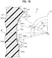
- FIG. 19 is a cross-sectional view taken along line II-II in FIG. 18B to show grooved parts of the ball seat.
- the ball seat 12 is hollowed in the present embodiment at two portions apart from the equator or the latitude of 90 degrees, to form grooved parts 12ml, 12m2 for making a gap at the portions, where the ball seat 12 contacts the ball part 10b of the ball stud 10, so as to reduce the torque of the ball stud 10.
- the grooved parts 12ml, 12m2 in a recessed shape are formed so as to have the central points offset from the central point C of the ball part 10b of the ball stud 10.
- the ball seat 12 is formed by injection molding.
- the grooved parts 12m1, 12m2 are formed during the injection molding.
- the bottom part 12mt of the grooved parts 12ml, 12m2 has substantially the same curvature as the ball part 10b of the ball stud 10 so as to have the centers of curvature offset from the central point of the ball part 10b. Therefore, even if the inner surface 12n of the ball seat 12 is deformed, the grooved parts 12m1, 12m2 allows the ball seat 12 to maintain a gap between the ball seat 12 and the ball part 10b of the ball stud 10.
- grooved parts 12m1, 12m2 may have a cross section other than a rectangular shape or the like, as long as a gap is maintained when the ball seat 12 is deformed.
- a zone of the inner surface 12n forming the spherical space 12k on which the ball part 10b slides, exclusive of the grooved parts 12m1, 12m2, may preferably occupy 38.5 % or more of a zone of the inner surface 12n defined by top and bottom circles of latitude in correspondence with a central angle of 63 to 75 degrees. This allows for supporting the ball part 10b of the ball stud 10. Note that the zone for sliding is restricted from the determined torque value and the elastic lift.
- the ball seat 12 includes the main body 12a in a cup shape and the flange part 12b formed around the opening of the main body 12a.
- the main body 12a has the three bosses 12o at the bottom, extending downward, so as to be fixed into the housing 11 by hot pressure welding.
- the main body 12a has eight grease grooves 12r formed on the inner surface 12n thereof, in which grease is retained, in the direction of the axis J1 of the ball seat 12.
- the grease groove 12r has the width of about 2 mm.
- the main body 12a has the grooved parts 12ml, 12m2 arranged in the upper and lower portions of the inner surface 12n thereof across the equator, which are circumferentially recessed for reducing the torque of the ball stud 10.
- the grooved parts 12ml, 12m2 are circumferentially arranged about the axis J1 of the ball seat 12. Note that the grooved parts 12m1, 12m2 may be discontinuously provided.
- the distributed rotating torque Tri and distributed swinging torque Toi are shown in FIG. 17 .
- the ball seat 12 has eight grease grooves 12r having a width of 2 mm formed in the inner surface 12n thereof. From the viewpoint of being formed by injection molding and supporting the ball part 10b of the ball stud 10 by the contact surface pressure at the upper and lower end lines, the ball seat 12 has end surfaces 12t1, 12t2 reserved at the upper and lower ends, each of which has a width s1 (see FIG. 19 ) of about 1 mm.
- the width s1 of the upper and lower end surfaces of the ball seat 12 is preferably 0.5 mm or more.
- the two grooved parts 12m1, 12m2 are circumferentially formed in the vicinity of the end surfaces 12t1, 12t2 where the torque is most effectively reduced.
- FIG. 20 is a chart indicating locations of the grooved parts of the present embodiment with respect to the rotating and swinging torque of the ball part of the ball stud at each latitude in FIGS. 18A and 18B .
- the grooved part 12ml occupies a zone ranging from 56 to 76 degrees and the grooved part 12m2 occupies a zone ranging from 99 to 107 degrees.
- the grooved parts 12ml, 12m2 are represented by the bottoms thereof to indicate these zones.
- the grooved parts 12m1, 12m2 are arranged to have a depth "f" of 0.1 to 0.2 mm or so, considering the inner pressure while the ball part 10b of the ball stud 10 is inserted onto the ball seat 12 at the time of assembly, and the tensile load due to detaching a male mold as well as detachability of a male mold at the time of molding.
- the grooved parts 12ml, 12m2 may have a depth "f" of 0.08 to 0.25 mm, most preferably a depth of 0.1 to 0.2 mm or so.
- the upper and lower ends of the grooved parts 12m1, 12m2 continue to the bottoms thereof via tapered (or inclined) surfaces at an angle ⁇ 3 of at least 50 degrees or more to a normal line to the spherical inner surface 12n of the ball seat 12, considering detachability of a male mold at the time of molding and contact continuity from the spherical part (inner surface 12n) to the grooved parts 12ml, 12m2.
- the ball seat 12 includes a tapered (or inclined) surface continuing from the inner surface 12n to the grooved part 12ml or 12m2 at an angle ⁇ 3 of about 50 degrees or more with respect to a normal line to the tangent of the ball part 10b.
- this tapered (or inclined) surface is arranged for removing the mold from the opening of the ball seat 12, so that the angle ⁇ 3 is preferably 50 degrees or more.
- the sizes and positions of the grooved parts 12m1, 12m2 are adjusted to set the swinging torque of the ball stud 10 with respect to the stabilizer link 1 to 0.5 Nm or less and to set the rotating torque to 0.5 Nm or less.
- Hollowing the ball seat 12 of the present embodiment in zones effective for the rotating and swinging torque allows the swinging and rotating torque of the ball stud to be adjusted so as to have desired values.
- the ball seat 12 according to a modification is a connection part of the stabilizer link 1 having a gap in the vicinity of the equator of the ball part 10b of the ball stud 10, as shown in FIGS. 21A and 21B.
- FIGS. 21A and 21B show the structure of the ball seat 12 of the modification.
- FIG. 21A is a longitudinal sectional view of a ball seat of the modification to show the internal structure thereof
- FIG. 21B is a bottom view of the ball seat.
- FIG. 22 is a cross-sectional view taken along a line IV-IV in FIG. 21B to show a grooved part of the ball seat.
- FIG. 23 is a chart indicating a location of the grooved part of the modification with respect to the rotating and swinging torque of the ball part of the ball stud at each latitude in FIGS. 21A and 21B .
- the ball seat 12 of the modification has a grooved part 12m3 formed circumferentially near the equator (a portion of the ball seat 12 having the maximum radius about the axis J1 which runs through the centers of the opening 12i and the grease chamber 12c) of the inner surface 12n of the spherical part of the ball seat 12. More specifically, assuming that the latitude is 0 degree on the axis J1 extending toward the opening 12i, the grooved part 12m3 occupies a zone ranging from 78 to 103 degrees (see FIG. 23 ).
- the grooved part 12m3 is formed in the same manner as the grooved parts 12ml, 12m2 of the present embodiment. That is, the ball seat 12 is formed by injection molding.
- the grooved part 12m3 is formed at the time of injection molding.
- a zone of the inner surface 12n forming the spherical space 12k on which the ball part 10b slides, exclusive of the grooved part 12m3, may preferably occupy 38.5 % or more of a zone of the inner surface 12n defined by top and bottom circles of latitude in correspondence with a central angle of 63 to 75 degrees. Note that the zone for sliding is restricted from the determined torque value and the elastic lift.
- the grooved part 12m3 is arranged to have a depth "f" of 0.1 to 0.2 mm or so, considering the inner pressure while the ball part 10b of the ball stud 10 is inserted onto the ball seat 12 at the time of assembly, and the tensile load due to detaching a male mold as well as detachability of a male mold at the time of molding.
- the grooved part 12m3 may have a depth "f" of 0.08 to 0.25 mm, but the most preferable depth is 0.1 to 0.2 mm or so.
- the upper and lower ends of the grooved part 12m3 continue to the bottom thereof via tapered (or inclined) surfaces at an angle ⁇ 4 of at least 50 degrees or more with respect to a normal line to the spherical inner surface 12n of the ball seat 12, considering detachability of a male mold at the time of molding and contact continuity from the spherical part (inner surface 12n) to the grooved part 12m3.
- the tapered (or inclined) surface is arranged for removing the mold from the opening of the ball seat 12, so that the angle ⁇ 4 is preferably 50 degrees or more.
- the swinging torque of the ball stud 10 with respect to the stabilizer link 1 is set to 0.5 Nm or less and the rotating torque is set to 0.5 Nm or less.
- Table 1 summarises comparison results between Comparative Example 1 having no groove (grease groove 12r) or grooved part arranged between the ball seat 12 and the ball part 10b of the ball stud 10, Comparative Example 2 having the grease grooves 12r arranged therebetween, Modification having the grease grooves and a grooved part arranged therebetween (see FIGS. 21A and 21B ), and the present embodiment having the grease grooves and two grooved parts arranged therebetween (see FIG. 18A ), wherein the single grooved part is arranged near the equator and the two grooved parts are arranged above and below the equator to reduce area of contact between the ball seat 12 and the ball part 10b.
- Comparative Example 2 has eight grease grooves 12r having a width of 2 mm arranged, but has no grooved parts 12m1, 12m2, 12m3 arranged circumferentially as in the present embodiment. Comparative Example 2 has area of contact of 288.4 mm 2 between the ball part 10b of the ball stud 10 and the ball seat 12. The area of contact of 288.4 mm 2 in Comparative Example 2 is reduced by 34.3 % as compared to that of 438.8 mm 2 in Comparative Example 1. Comparative Example 2 has the rotating torque of 383.9 Nmm about the axis of the ball stud 10, and the swinging torque of 423.1 Nmm with which the ball stud 10 swings.
- Modification has eight grease grooves 12r having a width of 2 mm arranged, and has an equatorial groove (grooved part 12m3) arranged near the equator of the ball seat 12 (circle of latitude having the largest radius about the axis J1 which runs through the centers of the opening 12i of the ball seat 12 and the grease chamber 12c). Assuming that the latitude is 0 degree on the axis J1 extending toward the opening 12i and the latitude is 180 degrees on the axis J1 extending toward the grease chamber 12c, Modification has the equatorial groove formed in a zone of the latitude of 78 to 103 degrees (see FIG. 23 ). The area of contact of 169.2 mm2 in Modification is reduced by 61.4 % as compared to that of 288.4 mm2 in Comparative Example 2.
- Modification has the rotating torque of 331.1 Nmm about the axis of the ball stud 10, and this has been reduced by 14 % as compared to that of 383.9 Nmm in Comparative Example 2.
- Modification has the swinging torque 369.6 Nmm with which the ball stud 10 swings, and this has been reduced by 13 % as compared to that of 423.1 Nmm in Comparative Example 2.
- the present embodiment has eight grease grooves 12r having a width of 2 mm arranged, and has two grooved parts 12m1, 12m2 arranged above and below the equator of the ball seat 12 (circle of latitude having the largest radius about the axis J1 which runs through the centers of the opening 12i of the ball seat 12 and the grease chamber 12c). Assuming that the latitude is 0 degree on the axis J1 extending toward the opening 12i and the latitude is 180 degrees on the axis J1 extending toward the grease chamber 12c, the present embodiment has the grooved parts 12m1, 12m2 formed in two zones having the latitude of 56 to 76 degrees and the latitude of 99 to 107 degrees (see FIG. 20A ), respectively.
- the area of contact of 169.3 mm 2 in the present embodiment is reduced by 61.4 % with respect to that of 288.4 mm2 in Comparative Example 2.
- the present embodiment has the rotating torque of 214.1 Nmm about the axis of the ball stud 10, which has been reduced by 44 % as compared to that of 383.9 Nmm in Comparative Example 2 and has been reduced by 35 % as compared to that of 331.1 Nmm in Modification.
- the present embodiment has the swinging torque of 238.3 Nmm with which the ball stud 10 swings, which has been reduced by 44 % as compared to that of 423.1 Nmm in Comparative Example 2 and has been reduced by 35 % as compared to that of 369.6 Nmm in Modification.
- the above configuration allows the swinging torque of the ball stud 10 swinging the stabilizer link 1 to be set to 0.5 Nm or less, and allows the rotating torque of the ball stud 10 rotating to be set to 0.5 Nm or less. Therefore, the swinging torque of the ball stud 10 swinging the stabilizer link 1 and the rotating torque of the ball stud 10 rotating the stabilizer link 1 are reduced to improve ride quality, dynamic characteristics, and durability of the vehicle using the stabilizer link 1.
- grooved parts 12m1, 12m2 and the grooved part 12m3 are adjusted as appropriate to have the desired swinging and rotating torque while supporting the ball stud 10.
- suitably adjusting the torque and the elastic lift allows for suppressing accelaration of mutual wearing of parts around the stabilizer link 1 at the time of market use.
- This causes stablizer links having poor dynamic characteristics to be less used in the market to allow the stablizer link having good dynamic characteristics to prevail.
- this allows for suppressing abnormal noise from around the stabilizer link 1.
- the stabilizer link 1 is capable of effectively suppressing loosening between the ball part 10b of the ball stud 10 and the ball seat 12, which is included in the housing 11 to receive the ball part 10b so as to be slidable, to allow the ball stud 10 to have reduced torque at the time of the ball stud 10 swinging and the rotating.
Landscapes
- Engineering & Computer Science (AREA)
- General Engineering & Computer Science (AREA)
- Mechanical Engineering (AREA)
- Physics & Mathematics (AREA)
- Geometry (AREA)
- Pivots And Pivotal Connections (AREA)
- Vehicle Body Suspensions (AREA)
Abstract
Description
- The present invention relates to a stabilizer link to be connected with a suspension of a vehicle.
- A vehicle conventionally includes a suspension and a stabilizer, as disclosed in
Patent Document 1. The suspension includes an oil damper and a compression coil spring to reduce the impact transmitted from the road surface to the vehicle body. - The stabilizer uses a restoring force caused by torsional deformation of a bar to increase roll stiffness (rigidity against torsion) of the vehicle body. The suspension and the stabilizer are connected with each other via a stabilizer link. The stabilizer link is formed to have one connecting part to be fixed to the suspension and the other connecting part to be fixed to the stabilizer, which are arranged at both ends of a solid or hollow support bar.
- Each of the connecting parts arranged at both ends of the support bar has a ball joint structure to include a ball stud and a housing for accommodating the ball stud. The housings of the connecting parts are integrally attached to both ends of the support bar. The housing is a member in a cup shape to accommodate a sphere part (ball part) of the ball stud so as to be slidable. The housing includes therein a resin supporting member (ball seat). The ball part of the ball stud is received by the ball seat so as to be slidable.
- The ball part is slidable on the inner surface of the ball seat to allow the ball stud to be swingable and rotatable. The stabilizer link has a ball joint structure as described above in each of the connecting parts at both ends, to movably connect the suspension with the stabilizer.
- For the ball stud smoothly swinging and rotating, the frictional force between the ball part and the ball seat is preferably maintained at a low value as designed. Here, the ball seat receiving the ball part is made of resin. Accordingly, the size largely varies at the time of molding to make it difficult for the frictional force between the ball part and the ball seat to be maintained.
- Patent Document 1: Japanese Patent Application Publication No.
2011-247338 - Characteristics of movement between the suspension and the stabilizer affect steering stability of a vehicle, smoothness of the steering, ride quality, and the like. For example, if the torque of the ball stud swinging and rotating is large, the suspension and the stabilizer stiffly operate with each other to have problems such as lack of smoothness in operation and degradation of ride quality. Also, if the interference between the ball part and the ball seat is small, the ball part and the ball seat have reduced friction accordingly but suffer from loosening (elastic lift) therebetween. Such loosening causes noise and instability of ride quality, and therefore deteriorates the vehicle quality.
- The stabilizer link is a part having a ball joint structure that connects the stabilizer with a strut, an arm, and the like. As the suspension of the vehicle strokes, the stabilizer link is swung and rotated, and these characteristics are defined as swinging torque and rotating torque.
- Reducing suspension friction has been increasingly required for the purpose of improving ride quality of vehicle. Accordingly, the stabilizer link as a suspension part is required to have its swinging and rotating torque reduced. Decreasing the interference between the ball seat and the housing leads to reducing the torque but at the same time causes the elastic lift to be increased.
- The ball seat is a resin part and is manufactured by injection molding. The wall of the ball seat is formed to be thicker downward and thinner upward in the axial direction of the ball stud, and then the ball seat is not formed to have a constant outer radius due to the influence of heat shrinkage during molding, to have a tapered shape of being narrower downward and being wider upward. That is, a flange portion is formed in such a shape that the opening side of the main body extends peripherally outward. In contrast, the housing into which the ball seat is fitted is formed to have the inner radius being vertically straight in the axial direction of the ball stud, and therefore the ball seat and the housing contact less with each other as the interference therebetween is decreased, to have elastic lift increased.
- As a result, the ball joint part (connection part) may suffer from loosening to have abnormal noise while the vehicle is traveling. This loosening deteriorates accurate dynamic characteristics of the stabilizer link system. Besides, the elastic lift accelerates wearing of mutual parts to further increase the occurrence of abnormal noise and inaccurate dynamic characteristics of the stabilizer link system. As the elastic lift increases inversely with torque reduction, there is a limit to the torque reduction of the ball stud.
- The present invention has been devised in view of the above circumstances, and is intended to provide a stabilizer link that effectively suppresses loosening between a spherical part of a ball stud and a support member, which is arranged in a housing to receive the spherical portion so as to be slidable, and allows torque of the ball stud swinging and rotating to be reduced.
- In order to solve the above-mentioned problems, a stabilizer link according to a first aspect of the present invention includes: an arm part; and connecting parts that are arranged at both ends of the arm part, wherein one of the connecting parts is connected to a first structure and the other of the connecting parts is connected to a second structure, and at least one of the connecting parts has a ball joint structure, wherein the connecting part having the ball joint structure includes: a housing that supports a ball stud to be connected to the first or second structure so as to be swingable and rotatable, the ball stud having a spherical part and a stud part extending from the spherical part; and a support member that receives the spherical part in a spherical space so as to be slidable for the housing to support the ball stud, and includes: an opening where the spherical space is open for the stud part extending therethrough; a lubricant receiving part in a concave shape that is formed at a bottom opposed to the opening; and a wall surface that forms the spherical space for the spherical part to slide thereon and has recessed grooves formed circumferentially about the central axis of the spherical space running from the opening to the lubricant receiving part, on both sides or one side in the central axis direction of a portion of the wall surface having the maximum inner radius about the central axis.
- According to the first aspect of the present invention, the wall surface of the support member forms the spherical space for the spherical part to slide thereon and has the recessed grooves formed circumferentially about the central axis of the spherical space running from the opening to the lubricant receiving part, on both sides or one side in the central axis direction of the portion of the wall surface having the maximum inner radius about the central axis, to allow the ball stud to be well supported yet to have reduced torque.
- A second aspect of the present invention is the stabilizer link according to the first aspect of the present invention, wherein the recessed grooves are formed in zones of the wall surface where the torque required for sliding the spherical part in the spherical space is larger than that in the other zones except an end of the wall surface.
- According to the second aspect of the present invention, the recessed grooves are formed in zones of the wall surface where the torque required for sliding the spherical part in the spherical space is larger than that in the other zones except the end of the wall surface, to allow the ball stud to have reduced torque even if a recessed groove is formed in a narrow zone. As the torque is effectively reduced, the recessed groove may occupy a relatively narrow zone for reliably supporting the ball stud.
- A third aspect of the present invention is the stabilizer link according to the first or second aspect of the present invention, wherein the size of the recessed groove is determined so that the torque required for sliding the spherical part in the spherical space is 0.5 Nm or less.
- According to the third aspect of the present invention, the size of the recessed groove is determined so that the torque required for sliding the spherical part in the spherical space is 0.5 Nm or less, to allow the ball stud to have reduced torque as desired.
- A stabilizer link according to a fourth aspect of the present invention includes: an arm part; and connecting parts that are arranged at both ends of the arm part, wherein one of the connecting parts is connected to a first structure and the other of the connecting parts is connected to a second structure, and at least one of the connecting parts has a ball joint structure, wherein the connecting part having the ball joint structure includes: a housing that supports a ball stud to be connected to the first or second structure so as to be swingable and rotatable, wherein the ball stud has a spherical part and a stud part extending from the spherical part; and a support member that receives the spherical part in a spherical space so as to be slidable for the housing to support the ball stud, and includes: an opening where the spherical space is open for the stud part extending therethrough; a lubricant receiving part in a concave shape that is formed at a bottom opposed to the opening; and a wall surface that forms the spherical space for the spherical part to slide thereon and has a recessed groove formed circumferentially about the central axis of the spherical space running from the opening to the lubricant receiving part, in the vicinity of a portion of the wall surface having the maximum inner radius about the central axis, wherein the size of the recessed groove is determined so that the torque required for sliding the spherical part in the spherical space is 0.5 Nm or less.
- According to the fourth aspect of the invention, the wall surface of the support member forms the spherical space for the spherical part to slide thereon and has the recessed groove formed circumferentially about the central axis of the spherical space running from the opening to the lubricant receiving part, in the vicinity of the portion of the wall surface having the maximum inner radius about the central axis, wherein the size of the recessed groove is determined so that the torque required for sliding the spherical part in the spherical space is 0.5 Nm or less, to allow the ball stud to have the swinging torque and the rotating torque reduced as desired.
- A fifth aspect of the present invention is the stabilizer link according to any one of the first, second, and fourth aspects of the present invention, wherein a zone of the wall surface forming the spherical space, on which the spherical part slides, occupies 38.5 % or more of a zone of the same defined by top and bottom circumferences of the spherical space in correspondence with a central angle of 63 to 75 degrees.
- According to the fifth aspect of the present invention, the zone of the wall surface forming the spherical space, on which the spherical part slides, occupies 38.5 % or more of the zone of the same defined by top and bottom circumferences of the spherical space in correspondence with a central angle of 63 to 75 degrees, to allow the ball stud to be reliably supported.
- A sixth aspect of the present invention is the stabilizer link according to any one of the first, second, and fourth aspects of the present invention, wherein the distance between an edge of the spherical space, on which the spherical part slides, and the outmost recessed groove is 0.5 mm or more.
- According to the sixth aspect of the present invention, the support member reliably supports the spherical part of the ball stud. In addition, at the time of the die being removed from the spherical space of the support member, the support member forming the spherical space is inhibited from chipping.
- A seventh aspect of the present invention is the stabilizer link according to any one of the first, second, and fourth aspects of the present invention, wherein an end of the recessed groove continues to the wall surface in the spherical space at an angle of 50 degrees or more to a normal line to the wall surface.
- According to the seventh aspect of the present invention, the end of the recessed groove continues to the wall surface in the spherical space at an angle of 50 degrees or more to a normal line to the wall surface, to falicitate removing the die at the time of forming the support member.
- An eighth aspect of the present invention is the stabilizer link according to any one of the first, second, and fourth aspects of the present invention, wherein the depth of the recessed groove is 0.08 mm to 0.25 mm.
- According to the eighth aspect of the present invention, the depth of the recessed groove is 0.08 mm to 0.25 mm, to avoid the recessed groove from impairing its function when the support member is deformed. In addition, the strength of the support member is ensured.
- A ninth aspect of the present invention is the stabilizer link according to any one of the first, second, and fourth aspects of the present invention, wherein an upper end of the spherical part in a direction of the axis of the stud part is exposed on the outside of the spherical space.
- According to the ninth aspect of the present invention, the upper end of the spherical part in the direction of the axis of the stud part is exposed on the outside of the spherical space, to allow the ball stud to be smoothly operated.
- A tenth aspect of the present invention is the stabilizer link according to any one of the first, second, and fourth aspects of the present invention, wherein the support member is made of a thermoplastic resin and is injection molded to form the recessed groove.
- According to the tenth aspect of the present invention, the support member is made of a thermoplastic resin and is injection molded to form the recessed groove, to facilitate forming the recessed groove.
- The present invention provides a stabilizer link that effectively suppresses loosening between the spherical part of the ball stud and the support member, which is accommodated in the housing to receive the spherical part so as to be slidable, to cause the torque of the ball stud swinging and rotating to be reduced.
-
-
FIG. 1 is a perspective view of a stabilizer link connecting a suspension damper with a torsion bar; -
FIG. 2 is an exploded perspective view of disassembled area I inFIG. 1 ; -
FIG. 3 is a longitudinal sectional view of a connecting part of the stabilizer link; -
FIG. 4 is a longitudinal sectional view of a ball seat having a ball part of a ball stud fitted therein; -
FIG. 5 is a chart showing the correlation between the radius of an inner surface of a main body of a housing and the outer radius of the ball seat; -
FIG. 6 is a chart showing the correlation between the interference between the outer surface of the ball seat and the inner surface of the main body of the housing, and the swinging torque of the ball stud; -
FIG. 7 is a chart showing the correlation between the interference between the outer surface of the ball seat and the inner surface of the main body of the housing, and the elastic lift; -
FIG. 8A is a chart showing the correlation, before a durability test, between the deflection of the outer surface of the ball seat and the load; -
FIG. 8B is a chart showing the correlation, after a durability test, between the deflection of the outer surface of the ball seat and the load; -
FIG. 9 is a longitudinal sectional view of a ball seat having grease grooves formed to show the internal structure thereof; -
FIG. 10 is a cross-sectional view of the connecting part of the stabilizer link with the ball stud in an equilibrium state (setup state) to show the internal structure thereof; -
FIG. 11 is a cross-sectional view of the connecting part of the stabilizer link with the ball stud swinging to show the internal structure thereof; -
FIG. 12 is a conceptual diagram showing the center offset of the inner surface of the ball seat; -
FIG. 13 is a chart showing the correlation between the percentage of contact between the ball part of the ball stud and the inner surface of the ball seat, and the swinging torque and elastic lift (loosening) when the ball stud swings; -
FIG. 14 is a schematic diagram showing the equator, circle of longitude, and circle of latitude of the ball part of the ball stud; -
FIG. 15 is a chart showing the contact surface pressure per unit longitude by the angle from the equator, when the ball seat gaplessly contacts the ball part of the ball stud inFIG. 11 ; -
FIG. 16 is a chart showing the contact surface pressure per unit latitude by the angle from the equator, when the ball seat gaplessly contacts the ball part of the ball stud inFIG. 11 , by integrating (adding) the pressure for each latitude; -
FIG. 17 is a chart qualitatively showing the rotating and swinging torque of the ball part of the ball stud inFIG. 14 at each latitude; -
FIG. 18A is a longitudinal sectional view of the ball seat of the present embodiment to show the internal structure thereof; -
FIG. 18B is a bottom view of the ball seat; -
FIG. 19 is a cross-sectional view taken along a line II-II inFIG. 18B to show grooved parts of the ball seat; -
FIG. 20 is a chart indicating locations of the grooved parts of the present embodiment with respect to the rotating and swinging torque of the ball part of the ball stud at each latitude inFIG. 18A ; -
FIG. 21A is a longitudinal sectional view of a ball seat of a modification to show the internal structure thereof; -
FIG. 21B is a bottom view of the ball seat; -
FIG. 22 is a cross-sectional view taken along a line IV-IV inFIG. 21B to show a grooved part of the ball seat; and -
FIG. 23 is a chart indicating a location of the grooved part of the modification with respect to the rotating torque and swinging torque of the ball part of the ball stud at each latitude inFIGS. 21A and 21B . - Hereinafter, embodiments of the present invention will be described in detail with reference to the drawings as appropriate.
-
FIG. 1 is a perspective view of a stabilizer link according to an embodiment of the present invention connecting a suspension damper with a stabilizer. - A wheel W used for a vehicle (not shown) travelling is attached to a vehicle body (not shown) via a
suspension 3. Thesuspension 3 includes acoil spring 3a and asuspension damper 3b. Thesuspension damper 3b rotatably supports the wheel W. Thesuspension damper 3b and thecoil spring 3a damp the impact applied to the vehicle body from the wheel W. Thesuspension damper 3b is attached to the vehicle body (not shown) via thecoil spring 3a. The viscous damping force of thesuspension damper 3b at the time of expansion and contraction and the elastic force of thecoil spring 3a are used to damp vibration transmitted to the vehicle body by thesuspension 3. - A
stabilizer 2 is connected between the right and leftsuspensions 3. Thestabilizer 2 increases the roll rigidity (rigidity against torsion) of the vehicle body to prevent the vehicle from rolling. Thestabilizer 2 has atorsion bar 2a and a pair ofarm parts 2b extending in a U-shape from both ends of thetorsion bar 2a. - The
stabilizer 2 is formed with a rod-shaped spring member which is appropriately bent according to the shape of the vehicle. Thestabilizer 2 connects the twosuspension dampers 3b, respectively supporting the two opposed wheels W, with each other via astabilizer link 1 of the present embodiment. - One end of one
arm part 2b of thestabilizer 2 continues to one end of thetorsion bar 2a, while the other end of onearm part 2b is connected to oneconnection part 1b of thestabilizer link 1 . The other connectingpart 1b of thestabilizer link 1 is connected to thesuspension damper 3b. - Likewise, one end of the
other arm part 2b of thestabilizer 2 continues to the other end of thetorsion bar 2a, while the other end of theother arm part 2b is connected to oneconnection part 1b of thestabilizer link 1 . The other connectingpart 1b of thestabilizer link 1 is connected to thesuspension damper 3b. - The
torsion bar 2a extends from onesuspension damper 3b toward theother suspension damper 3b. Thearm parts 2b are shifted, such as when the vehicle turns, via thestabilizer link 1 due to the difference in expansion and contraction amount between the twosuspension dampers 3b to twist thetorsion bar 2a. Thetorsion bar 2a suppresses the rolling of the vehicle by the torsional elastic force acting to restore the torsion. -
FIG. 2 is an exploded perspective view of disassembled area I inFIG. 1 . Thestabilizer link 1 is formed to include a rod-like support bar 1a and a connectingpart 1b. Two connectingparts 1b are arranged at both ends of thesupport bar 1a. Thesupport bar 1a is, for example, a rod-shaped member made of solid steel bar. -
FIG. 3 is a longitudinal sectional view of a connecting part of the stabilizer link. In the connectingpart 1b, aball stud 10 is supported so as to be swingable and rotatable. Theball stud 10 is accommodated in ahousing 11 of the connectingpart 1b. The connectingpart 1b includes adust boot 13 for preventing foreign matter from entering into thehousing 11. - Then, the
ball stud 10 supported by one connectingpart 1b is fastened and fixed to abracket 3c of thesuspension damper 3b (seeFIG. 2 ). In addition, theball stud 10 provided in the other connectingpart 1b is fastened and fixed to thearm part 2b of thestabilizer 2. - The
bracket 3c is attached to thesuspension damper 3b by spot welding or the like. Thebracket 3c has a flat part for fixing that extends so as to face thearm part 2b of the stabilizer 2 (on the center side of the vehicle not shown). A flat part 3c1 of thebracket 3c has a mounting hole 3c2 opened. - In addition, the
ball stud 10 has aflange part 10a, which peripherally extends, formed on astud part 10s. Amale screw 10n is threaded on a distal end of thestud 10s beyond theflange part 10a. - Accordingly, one
ball stud 10 has thestud part 10s inserted into the mounting hole 3c2 of thebracket 3c up to theflange part 10a which peripherally extends. Then, a nut N1 is screwed onto themale screw 10n threaded on thestud part 10s of theball stud 10 which has been inserted through the mounting hole 3c2, to fix theball stud 10 to thesuspension damper 3b. - Further, the
stabilizer link 1 has thearm part 2b plastically deformed into a flat shape in the vicinity of a distal end 2b1 so as to have an attachment hole 2b2 penetrated. For example, as shown inFIG. 2 , thearm part 2b of thestabilizer link 1 has the distal end 2b1 and its vicinity plastically deformed into a flat face so as to face thesuspension damper 3b, and has the attachment hole 2b2 opened in the distal end 2b1. - The
other ball stud 10 has thestud part 10s inserted into the mounting hole 2b2 of thearm part 2b of thestabilizer 2 upto theflange part 10a. Then, a nut N2 is screwed onto themale screw 10n threaded on thestud part 10s of theball stud 10 which has been inserted through the mounting hole 2b2, to fix theball stud 10 to thearm part 2b of thestabilizer 2. - As described above, the
stabilizer link 1 is fixed to thesuspension damper 3b and thearm part 2b of thestabilizer 2 via theball studs 10 arranged at both ends of thesupport bar 1a. Theball stud 10 is supported by the connectingpart 1b of thestabilizer link 1 so as to be swingable and rotatable. Accordingly, thestabilizer link 1 is movable with respect to thesuspension damper 3b and thetorsion bar 2a. Thus, thestabilizer link 1 is a member to be connected to thestabilizer 2 and thesuspension 3. - As described above, the
stabilizer link 1 has the connectingparts 1b arranged at both ends of thesupport bar 1a. The connectingpart 1b includes thehousing 11 in a cup shape for accommodating aball part 10b of theball stud 10. Thehousing 11 is attached to each end of thesupport bar 1a by resistance welding or the like. Thehousing 11 is made of a steel material such as carbon steel for machine structural use and houses therein aball seat 12 made of resin as a support member. - As shown in
FIG. 3 , theball stud 10 includes theball part 10b in a substantially spherical shape and thestud part 10s unidirectionally extending from theball part 10b. Theball stud 10 is received in theball seat 12 of the connectingpart 1b at theball part 10b. - The
ball part 10b of theball stud 10 is formed in a true sphere or a shape close to a true sphere. The upper part of theball part 10b continues to thestud part 10s, while the lower part of theball part 10b is geometrically restricted in order to secure volume of agrease chamber 12c. Theball part 10b of theball stud 10 is formed in a true sphere or a shape close to a true sphere within an allowance. -
FIG. 4 is a longitudinal sectional view of theball seat 12 having the ball part of theball stud 10 fitted therein. Theball seat 12 is formed of resin by injection molding. Theball seat 12 is made of a thermoplastic resin such as POM (Polyacetal), PA6 (Polyamide 6), and PA66 (Polyamide 66). - The
ball seat 12 is formed into a tapered shape in which the outer radius of aflange part 12b is larger than that of amain body 12a due to molding shrinkage. Theball seat 12 is made of resin and includes themain body 12a and theflange part 12b. Themain body 12a is accommodated in the housing 11 (seeFIG. 3 ). Themain body 12a of theball seat 12 has a cup shape in which theball part 10b of theball stud 10 is tightly fitted. - In addition, the
main body 12a of theresin ball seat 12 is fixed into thehousing 11 by hot pressure welding. That is, themain body 12a is formed with bosses 12o for fixing. The bosses 12o which have penetrated holes in the bottom of thehousing 11 are melted to fix theball seat 12 in thehousing 11. The bosses 12o are pressed and welded in a heated state. - The
main body 12a of theball seat 12 encloses aspherical space 12k in a spherical shape. Then, theball part 10b of theball stud 10 is received in thespherical space 12k so as to be slidable. In addition, thestud part 10s of theball stud 10, which is integrally formed with theball part 10b, is moved together with theball part 10b. At this time, thestud part 10s has sliding torque applied thereto due to the sliding in thespherical space 12k of theball part 10b. Therefore, theball stud 10 received in theball seat 12 has thestud part 10s to be swingable and/or rotatable in accordance with the sliding of theball part 10b. In other words, thehousing 11 supports theball stud 10 so as to be swingable and/or rotatable. In this manner, the connectingpart 1b includes theball stud 10 having thestud part 10s and theball part 10b so as to be swingable and rotatable, to form a ball joint structure. At this time, swinging torque is applied to thestud part 10s when thestud part 10s swings, while rotating torque is applied to thestud part 10s when thestud part 10s rotates. That is, each of the swinging torque and the rotating torque is an aspect of the sliding torque. - The
ball part 10b is arranged to have its upper end in the axial direction of thestud part 10s exposed on the outside of the spherical space. Note that the extending direction of thestud part 10s in thestabilizer link 1 is suitably determined according to the positional relationship between thesuspension damper 3b (seeFIG. 2 ) and thearm part 2b of thestabilizer 2. - As shown in
FIG. 3 , thehousing 11 includes aflange part 11a and amain body 11b in a cup shape. Theflange part 11a is formed so as to peripherally extend at an opening of thehousing 11. In a state that themain body 12a of theball seat 12 is housed in themain body 11b of thehousing 11, theflange part 11a of thehousing 11 and theflange part 12b of theball seat 12 face each other. The end side of thedust boot 13 is held between theflange parts - The
dust boot 13 is a hollow member made of an elastic body such as rubber. Thedust boot 13 prevents foreign matter (dirt or the like) from entering into thehousing 11 or theball seat 12. - The
dust boot 13 is arranged around theball stud 10 between theflange part 10a thereof and theflange part 11a of thehousing 11. Thedust boot 13 has two openings 13a1, 13a2 at positions facing each other. One opening 13a1 is formed to peripherally bend inward, and this portion is held between theflange parts dust boot 13 is closely contacted with, and fixed to, thestud part 10s of theball stud 10. - The
dust boot 13 is shaped so as not to inhibit thestud part 10s from swinging and rotating. For example, thedust boot 13 preferably has a shape that largely bulges outward. Having a shape that largely bulges outward allows thedust boot 13 to cover thestud part 10s with a deformation allowance. As a result, thedust boot 13 is easily deformed in accordance with thestud part 10s swinging and/or rotating. This allows theball stud 10 to smoothly swing and rotate without being inhibited by thedust boot 13. -
FIG. 5 is a chart showing the correlation between the radius of an inner surface 11b1 (seeFIG. 3 ) of themain body 11b of thehousing 11 and the outer radius of theball seat 12. The horizontal axis inFIG. 5 indicates the radius, and the vertical axis inFIG. 5 indicates the height from a bottom surface 11b2 of thehousing 11. InFIG. 5 , the solid line indicates the position of the inner surface 11b1 of themain body 11b of thehousing 11, the broken line indicates the outer radius of a conventional ball seat having a large interference between the inner surface 11b1 of themain body 11b of thehousing 11 and anouter surface 12g of theball seat 12, and the bold solid line indicates the outer radius of the low-torque ball seat 12 having a small interference between the inner surface 11b1 of themain body 11b of thehousing 11 and theouter surface 12g (seeFIG. 3 ) of theball seat 12. - If the inner surface 11b1 of the
main body 11b of thehousing 11 is vertically straight to have an identical radius (inner radius), the inner surface 11b1 of thehousing 11 and the outer surface of the ball seat contact less with each other as the interference therebetween is reduced. In addition, if the interference between the inner surface 11b1 of themain body 11b of thehousing 11 and theouter surface 12g of theball seat 12 is increased (broken line inFIG. 5 ), the inner surface 11b1 of thehousing 11 and the outer surface of the ball seat contact more with each other, that is, improved, but the rate of theball seat 12 being pressed inward increases so that the torque at the time of theball stud 10 swinging increases. - On the contrary, if the interference between the inner surface 11b1 of the
main body 11b of thehousing 11 and theouter surface 12g of theball seat 12 is decreased (bold solid line inFIG. 5 ), the rate of theball seat 12 being pressed inward decreases so that the torque at the time of theball stud 10 swinging decreases. However, the elastic lift or the loosening between the inner surface 11b1 of themain body 11b of thehousing 11 and theouter surface 12g of theball seat 12 increases. -
FIG. 6 is a chart showing the correlation between the interference between the outer surface of theball seat 12 and the inner surface of the main body of the housing, and the swinging torque of the ball stud. The horizontal axis indicates the interference between theouter surface 12g of theball seat 12 and the inner surface 11b1 of themain body 11b of thehousing 11, and the vertical axis indicates the swinging torque of theball stud 10. The swinging torque of theball stud 10 decreases as the interference between theouter surface 12g of theball seat 12 and the inner surface 11b1 of themain body 11b of thehousing 11 decreases. - This is because if the interference is large, the
ball seat 12 is strongly pressed inward by the inner surface 11b1 of thehousing 11 to have the pressing force increased at the time of aninner surface 12n of theball seat 12 pushing theball part 10b of theball stud 10. On the contrary, if the interference is small, theball seat 12 is not strongly pressed inward by the inner surface 11b1 of thehousing 11 to have the pressing force decreased at the time of theinner surface 12n of theball seat 12 pushing theball part 10b of theball stud 10. -
FIG. 7 is a chart showing the correlation between the interference, between the outer surface of the ball seat and the inner surface of the main body of the housing, and the elastic lift. As the interference between theouter surface 12g of theball seat 12 and the inner surface 11b1 of themain body 11b of thehousing 11 decreases, the elastic lift, that is, the elastic lift (loosening) of theball seat 12 with respect to the inner surface 11b1 of themain body 11b of thehousing 11 increases. - This is because if the interference is large, the
ball seat 12 is strongly pressed inward by the inner surface 11b1 of thehousing 11 to have the elastic lift of theball seat 12 decreased with respect to the inner surface 11b1 of themain body 11b of thehousing 11. On the contrary, if the interference is small, theball seat 12 is not strongly pressed inward by the inner surface 11b1 of thehousing 11 to have the elastic lift of theball seat 12 increased with respect to the inner surface 11b1 of themain body 11b of thehousing 11. -
FIGS. 8A and8B are charts showing the presence or absence of an elastic lift before and after a durability test.FIG. 8A shows the correlation, before the durability test, between the deflection of the outer surface of the ball seat and the load, whileFIG. 8B shows the correlation, after the durability test, between the deflection of the outer surface of the ball seat and the load. InFIGS. 8A and8B , the horizontal axis indicates the deflection amount of theouter surface 12g of theball seat 12, and the vertical axis indicates the load. The broken lines inFIGS. 8A and8B indicate the cases where the interference between the inner surface 11b1 of themain body 11b of thehousing 11 and theouter surface 12g of theball seat 12 is normal, that is, the swinging and rotating torque of theball stud 10 is normal. The solid lines inFIGS. 8A and8B indicate the cases where the interference between the inner surface 11b1 of themain body 11b of thehousing 11 and theouter surface 12g of theball seat 12 is small, that is, the swinging and rotating torque of theball stud 10 is small. - Before the durability test, as shown in
FIG. 8A , the deflection is "0" when the load is set to "0" in both of the cases of the normal torque (broken line) and the small torque (solid line), to have no hysteresis observed. As described above, the interference is small in the case of the small torque, while the interference is large in the case of the normal torque. Accordingly, when a load is applied, the interference is small in the case of the small torque to have large amount of deflection, while the interference is large in the case of the normal torque to have small amount of deflection. - After the durability test, as shown in
FIG. 8B , small hysteresis was observed in the case of the normal torque (broken line). In the case of the small torque (solid line), hysteresis larger than that in the case of the normal torque was observed. Besides, even when the load was set to "0," the deflection was not "0" to have loosening. - It has been found from
FIG. 8B that if the torque is set to be small, the deflection amount of theouter surface 12g of theball seat 12 increases to have an unfavorable characteristic of the deflection amount of theball seat 12. - As it has been found from the results in
FIGS. 6 to 8B , if the interference between theouter surface 12g of theball seat 12 and the inner surface 11b1 of themain body 11b of thehousing 11 is large, the elastic lift is small but the swinging torque of theball stud 10 is large. On the contrary, if the interference between theouter surface 12g of theball seat 12 and the inner surface 11b1 of themain body 11b of thehousing 11 is small, the elastic lift is large but the swinging torque of theball stud 10 is small. -
FIG. 9 is a longitudinal sectional view of the ball seat having the grease groove formed to show the internal structure thereof. Theball seat 12 has eightgrease grooves 12r formed in the direction of the axis J1 of theball seat 12 for retaining grease therein. For example, thegrease groove 12r has a width of about 2 mm. Theball seat 12 has anopening 12i defined inside at the top thereof for theball stud 10 swinging and rotating. For example, a ray extending from the central point of theball seat 12 through the edge of theopening 12i is at an angle θ0 of about 23 to about 30 degrees to a center line J2 extending horizontally through the central point. - The
ball seat 12 has thegrease chamber 12c arranged inside at the bottom thereof. For example, a ray extending from the central point of theball seat 12 through the edge of thegrease chamber 12c is at an angle θ1 of about 40 to about 45 degrees to the ray J2. -
FIG. 10 is a cross-sectional view of the connecting part of the stabilizer link with the ball stud in an equilibrium state (setup state) to show the internal structure thereof.FIG. 11 is a cross-sectional view of the connecting part of the stabilizer link with the ball stud swinging to show the internal structure thereof. InFIGS. 10 and11 , cross sections of thehousing 11, theball seat 12, and thedust boot 13 are shown. - With the
ball stud 10 set in the connectingpart 1b of thestabilizer link 1, as shown inFIG. 11 , theball stud 10 is upright with respect to theball seat 12 in the connectingpart 1b of thestabilizer link 1. - As shown in
FIG. 10 , theball part 10b of theball stud 10 receives a surface pressure as indicated by arrows from the contactinginner surface 12n of theball seat 12. The frictional force between theball part 10b of theball stud 10 and the contactinginner surface 12n of theball seat 12 due to sliding action is the frictional force when theball stud 10 swings and rotates as shown inFIG. 11 , with respect to thestabilizer link 1. Therefore, this frictional force is the swinging and rotating torque when theball stud 10 swings and rotates. In other words, the sliding torque caused by the frictional force results in the swinging and rotating torque. -
FIG. 12 is a conceptual diagram showing the center offset of the inner surface of the ball seat. In the inner surface of theball seat 12, the upper inner surface 12nu closer to the opening has the central point O1 on the lower side, while the lower inner surface 12ns closer to the opposite side of the opening has the central point O2 on the upper side. As a result, theinner surface 12n of theball seat 12 is formed to have a higher surface pressure at an end portion (a portion of theball seat 12 closer to the opening or the opposite side of the opening) than at the equator (a portion of theball seat 12 having the maximum radius about the axis J1 which runs through the centers of theopening 12i (seeFIG. 10 ) and thegrease chamber 12c (seeFIG. 10 ) on its opposite side). In other words, the center offset inFIG. 12 allows the upper and lower end portions of theball seat 12 to have the maximum surface pressure distributed thereat. - The surface pressure to the
ball part 10b caused by the interference above the equator generates a reaction force on the lower part of theball seat 12 due to balancing of the static force, so that theball seat 12 has surface pressure distribution of having the maximum surface pressure at the two circles, top and bottom, i.e., the edge 12nl at theopening 12i (seeFIG. 9 ) and the edge 12n2 to the grease chamber (seeFIG. 9 ), to determine the ball position. -
FIG. 13 is a chart showing the correlation between the percentage of contact between the ball part of the ball stud and the inner surface of the ball seat, and the swinging torque and elastic lift when the ball stud swings. InFIG. 13 , the horizontal axis indicates the percentage of contact between theball part 10b of theball stud 10 and theinner surface 12n of theball seat 12, and the vertical axis indicates the magnitudes of the swinging torque and elastic lift. Note that the percentage of 100% on the horizontal axis means that there is no gap (inclusive of thegrease groove 12r) in the zone where theinner surface 12n of theball seat 12 contacts theball part 10b, as shown inFIG. 10 . - As shown in
FIG. 13 , as the ratio (percentage) of the contact between theball part 10b of theball stud 10 and theinner surface 12n of theball seat 12 increases, the swing torque increases while the elastic lift decreases in theball stud 10. On the contrary, as the contact ratio decreases, the swinging torque decreases while the elastic lift increases in theball stud 10. - Then, limiting the percentage in a range between the solid line and the broken line allows both the swing torque and elastic lift of the
ball stud 10 to have preferable small values. -
FIG. 14 is a schematic diagram showing the equator, circle of longitude, and circle of latitude of the ball part of the ball stud. The equator of theball part 10b of theball stud 10 means a circumferential portion thereof connecting spots having the longest radius about the vertical axis direction of thestud part 10s of thespherical ball part 10b. - The circle of longitude of the
ball part 10b is a circumferential line perpendicular to the equator of theball part 10b and corresponds to the circle of longitude set for the earth. The circle of latitude of theball part 10b is a circumferential line parallel to the equator of theball part 10b and corresponds to the circle of latitude set for the earth. -
FIG. 15 is a chart showing the contact surface pressure per unit longitude by the angle from the equator, when the ball seat gaplessly contacts the ball part of the ball stud shown inFIG. 11 . The horizontal axis inFIG. 15 indicates the latitude having 90 degrees at the equator, and decreasing with the increasing distance from the equator toward 0 degree at the center of theopening 12i, to have 48 degrees at the contacting point with the upper end of theball seat 12. On the other side, the angle increases with the increasing distance from the center of theopening 12i to have 115 degrees at the contacting point with the lower end of theball seat 12. The vertical axis inFIG. 15 indicates the level of the surface pressure. - The contact surface pressure per unit longitude was substantially "0" at the equator. The surface pressure increased substantially in a linear manner with the increasing distance from the equator toward the
stud part 10s, while it increased similarly with the increasing distance from thestud part 10s in a range from the equator to 100 degrees and some, and then increased sharply after the latitude exceeding 100 degrees and some. -
FIG. 16 is a chart showing the contact surface pressure per unit latitude by the angle from the equator, when the ball seat gaplessly contacts the ball part of the ball stud inFIG. 10 , by integrating (adding) the pressure for each latitude. The horizontal axis inFIG. 16 indicates the latitude having 90 degrees at the equator, and decreasing with the increasing distance from the equator toward 0 degree at the center of theopening 12i, to have 48 degrees at the contacting point with the upper end (edge 12nl inFIG. 9 ) of theball seat 12. On the other side, the angle increases with the increasing distance from the center of theopening 12i to have 115 degrees at the contacting point with the lower end (edge 12n2 inFIG. 9 ) of theball seat 12. The vertical axis inFIG. 16 indicates the level of the surface pressure. - The integrated value of the surface pressure per unit latitude was substantially "0" at the latitude of the equator. The value increased substantially in a quadratic curve with the increasing distance from the equator toward the
stud part 10s, while it increased similarly with the increasing distance from thestud part 10s in a range from the equator to 100 degrees and some, and then increased sharply after the latitude exceeding 100 degrees and some. - Here, the following equation holds true for a frictional force generated on the outer surface of the
ball part 10b;
ball stud 10 and the frictional force generated on the outer surface of theball stud 10b;

-
FIG. 17 is a chart qualitatively showing the rotating and swinging torque of the ball part of the ball stud shown inFIG. 14 at each latitude. InFIG. 17 , the horizontal axis indicates the latitude of theball part 10b of theball stud 10 inFIG. 14 , and the vertical axis indicates the level of the torque. The swinging torque at a time of thestud part 10s of theball stud 10 swinging is expressed by the product of the surface pressure and the radius "r" (seeFIG. 14 ) of theball part 10b. The rotating torque at a time of theball stud 10 rotating about the axis J1 (seeFIG. 14 ) of thestud part 10s is expressed by a value obtained by integrating the product of the surface pressure and the radius "ri" (seeFIG. 14 ) from the axis J1 of thestud part 10s to each circle of latitude. - As shown in
FIG. 17 , the swinging torque (solid line) is substantially "0" at the equator or the latitude of 90 degrees. On one side, the swinging torque increases with the increasing distance from the equator at the latitude of 90 degrees toward thestud part 10s of theball stud 10. On the other side, the swinging torque increases similarly with the increasing distance from thestud part 10s in a range from the latitude of 90 degrees at the equator to substantially 102 degrees, and then increases sharply after the latitude exceeding substantially 102 degrees. - Likewise, the rotating torque (broken line) is substantially "0" at the equator or the latitude of 90 degrees. On one side, the rotating torque increases with the increasing distance from the equator at the latitude of 90 degrees toward the
stud part 10s of theball stud 10. On the other side, the rotating torque increases similarly with the increasing distance from thestud part 10s in a range from the latitude of 90 degrees at the equator to substantially 102 degrees, and then increases sharply after the latitude exceeding substantially 102 degrees. - From the result in
FIG. 17 , both the swinging torque and the rotating torque increase with the increasing distance from the equator or the latitude of 90 degrees, and therefore hollowing theball seat 12 at a position away from the equator or the latitude of 90 degrees, making a gap between theball seat 12 and theball part 10b of theball stud 10, allows the torque of theball stud 10 to be effectively reduced. -
FIGS. 18A and 18B are diagrams showing the structure of theball seat 12 according to the present embodiment.FIG. 18A is a longitudinal sectional view of the ball seat of the present embodiment to show the internal structure thereof, andFIG. 18B is a bottom view of the ball seat according to the present embodiment.FIG. 19 is a cross-sectional view taken along line II-II inFIG. 18B to show grooved parts of the ball seat. - From the above-identified result, the
ball seat 12 is hollowed in the present embodiment at two portions apart from the equator or the latitude of 90 degrees, to form grooved parts 12ml, 12m2 for making a gap at the portions, where theball seat 12 contacts theball part 10b of theball stud 10, so as to reduce the torque of theball stud 10. The grooved parts 12ml, 12m2 in a recessed shape are formed so as to have the central points offset from the central point C of theball part 10b of theball stud 10. - The
ball seat 12 is formed by injection molding. The grooved parts 12m1, 12m2 are formed during the injection molding. - That is, the bottom part 12mt of the grooved parts 12ml, 12m2 has substantially the same curvature as the
ball part 10b of theball stud 10 so as to have the centers of curvature offset from the central point of theball part 10b. Therefore, even if theinner surface 12n of theball seat 12 is deformed, the grooved parts 12m1, 12m2 allows theball seat 12 to maintain a gap between theball seat 12 and theball part 10b of theball stud 10. - Note that the grooved parts 12m1, 12m2 may have a cross section other than a rectangular shape or the like, as long as a gap is maintained when the
ball seat 12 is deformed. - In addition, a zone of the
inner surface 12n forming thespherical space 12k on which theball part 10b slides, exclusive of the grooved parts 12m1, 12m2, may preferably occupy 38.5 % or more of a zone of theinner surface 12n defined by top and bottom circles of latitude in correspondence with a central angle of 63 to 75 degrees. This allows for supporting theball part 10b of theball stud 10. Note that the zone for sliding is restricted from the determined torque value and the elastic lift. - As shown in
FIG. 18A , theball seat 12 includes themain body 12a in a cup shape and theflange part 12b formed around the opening of themain body 12a. Themain body 12a has the three bosses 12o at the bottom, extending downward, so as to be fixed into thehousing 11 by hot pressure welding. As shown inFIG. 18B , themain body 12a has eightgrease grooves 12r formed on theinner surface 12n thereof, in which grease is retained, in the direction of the axis J1 of theball seat 12. For example, thegrease groove 12r has the width of about 2 mm. - In addition, the
main body 12a has the grooved parts 12ml, 12m2 arranged in the upper and lower portions of theinner surface 12n thereof across the equator, which are circumferentially recessed for reducing the torque of theball stud 10. The grooved parts 12ml, 12m2 are circumferentially arranged about the axis J1 of theball seat 12. Note that the grooved parts 12m1, 12m2 may be discontinuously provided. - The
ball part 10b of theball stud 10 fitted into theball seat 12 is supported by surface pressure Po of theball seat 12. If there is no grooved part 12ml or 12m2 in theball seat 12, per-longitude distributed surface pressure Poi is as shown inFIG. 15 . If theball seat 12 has no grooved part 12m, per-latitude distributed surface pressure Pai of theball part 10b of theball stud 10 is expressed with the following formula:
- The per-latitude distributed surface pressure Pai is shown in
FIG. 16 in a case where theball seat 12 has no grooved parts 12m1 or 12m2. FromFIG. 16 , distributed rotating torque Tri is expressed by multiplying the distributed surface pressure Pai by the radius "ri" for each latitude (seeFIG. 14 ):
ball part 10b:
- The distributed rotating torque Tri and distributed swinging torque Toi are shown in
FIG. 17 . The rotating torque Tr for rotating theball stud 10 is expressed as:
ball stud 10 is expressed as:
- As shown in
FIGS. 18A and 18B , theball seat 12 has eightgrease grooves 12r having a width of 2 mm formed in theinner surface 12n thereof. From the viewpoint of being formed by injection molding and supporting theball part 10b of theball stud 10 by the contact surface pressure at the upper and lower end lines, theball seat 12 has end surfaces 12t1, 12t2 reserved at the upper and lower ends, each of which has a width s1 (seeFIG. 19 ) of about 1 mm. The width s1 of the upper and lower end surfaces of theball seat 12 is preferably 0.5 mm or more. - Then, the two grooved parts 12m1, 12m2 are circumferentially formed in the vicinity of the end surfaces 12t1, 12t2 where the torque is most effectively reduced.
-
FIG. 20 is a chart indicating locations of the grooved parts of the present embodiment with respect to the rotating and swinging torque of the ball part of the ball stud at each latitude inFIGS. 18A and 18B . For example, assuming that the latitude is 0 degree on the axis J1 extending toward theopening 12i, the grooved part 12ml occupies a zone ranging from 56 to 76 degrees and the grooved part 12m2 occupies a zone ranging from 99 to 107 degrees. Note that the grooved parts 12ml, 12m2 are represented by the bottoms thereof to indicate these zones. - The grooved parts 12m1, 12m2 are arranged to have a depth "f" of 0.1 to 0.2 mm or so, considering the inner pressure while the
ball part 10b of theball stud 10 is inserted onto theball seat 12 at the time of assembly, and the tensile load due to detaching a male mold as well as detachability of a male mold at the time of molding. Note that the grooved parts 12ml, 12m2 may have a depth "f" of 0.08 to 0.25 mm, most preferably a depth of 0.1 to 0.2 mm or so. - As shown in
FIG. 19 , the upper and lower ends of the grooved parts 12m1, 12m2 continue to the bottoms thereof via tapered (or inclined) surfaces at an angle θ3 of at least 50 degrees or more to a normal line to the sphericalinner surface 12n of theball seat 12, considering detachability of a male mold at the time of molding and contact continuity from the spherical part (inner surface 12n) to the grooved parts 12ml, 12m2. - The
ball seat 12 includes a tapered (or inclined) surface continuing from theinner surface 12n to the grooved part 12ml or 12m2 at an angle θ3 of about 50 degrees or more with respect to a normal line to the tangent of theball part 10b. As theball seat 12 is formed by injection molding, this tapered (or inclined) surface is arranged for removing the mold from the opening of theball seat 12, so that the angle θ3 is preferably 50 degrees or more. - In the present embodiment, the sizes and positions of the grooved parts 12m1, 12m2 are adjusted to set the swinging torque of the
ball stud 10 with respect to thestabilizer link 1 to 0.5 Nm or less and to set the rotating torque to 0.5 Nm or less. - Hollowing the
ball seat 12 of the present embodiment in zones effective for the rotating and swinging torque allows the swinging and rotating torque of the ball stud to be adjusted so as to have desired values. - The
ball seat 12 according to a modification is a connection part of thestabilizer link 1 having a gap in the vicinity of the equator of theball part 10b of theball stud 10, as shown inFIGS. 21A and 21B. FIGS. 21A and 21B show the structure of theball seat 12 of the modification.FIG. 21A is a longitudinal sectional view of a ball seat of the modification to show the internal structure thereof, andFIG. 21B is a bottom view of the ball seat.FIG. 22 is a cross-sectional view taken along a line IV-IV inFIG. 21B to show a grooved part of the ball seat.FIG. 23 is a chart indicating a location of the grooved part of the modification with respect to the rotating and swinging torque of the ball part of the ball stud at each latitude inFIGS. 21A and 21B . - The
ball seat 12 of the modification has a grooved part 12m3 formed circumferentially near the equator (a portion of theball seat 12 having the maximum radius about the axis J1 which runs through the centers of theopening 12i and thegrease chamber 12c) of theinner surface 12n of the spherical part of theball seat 12. More specifically, assuming that the latitude is 0 degree on the axis J1 extending toward theopening 12i, the grooved part 12m3 occupies a zone ranging from 78 to 103 degrees (seeFIG. 23 ). The grooved part 12m3 is formed in the same manner as the grooved parts 12ml, 12m2 of the present embodiment. That is, theball seat 12 is formed by injection molding. The grooved part 12m3 is formed at the time of injection molding. - In addition, a zone of the
inner surface 12n forming thespherical space 12k on which theball part 10b slides, exclusive of the grooved part 12m3, may preferably occupy 38.5 % or more of a zone of theinner surface 12n defined by top and bottom circles of latitude in correspondence with a central angle of 63 to 75 degrees. Note that the zone for sliding is restricted from the determined torque value and the elastic lift. - The grooved part 12m3 is arranged to have a depth "f" of 0.1 to 0.2 mm or so, considering the inner pressure while the
ball part 10b of theball stud 10 is inserted onto theball seat 12 at the time of assembly, and the tensile load due to detaching a male mold as well as detachability of a male mold at the time of molding. Note that the grooved part 12m3 may have a depth "f" of 0.08 to 0.25 mm, but the most preferable depth is 0.1 to 0.2 mm or so. - As shown in
FIG. 22 , the upper and lower ends of the grooved part 12m3 continue to the bottom thereof via tapered (or inclined) surfaces at an angle θ4 of at least 50 degrees or more with respect to a normal line to the sphericalinner surface 12n of theball seat 12, considering detachability of a male mold at the time of molding and contact continuity from the spherical part (inner surface 12n) to the grooved part 12m3. As theball seat 12 is formed by injection molding, the tapered (or inclined) surface is arranged for removing the mold from the opening of theball seat 12, so that the angle θ4 is preferably 50 degrees or more. - In the modification, the swinging torque of the
ball stud 10 with respect to thestabilizer link 1 is set to 0.5 Nm or less and the rotating torque is set to 0.5 Nm or less. -
[Table 1] Comparative Example 1 (CE1) Comparative Example 2 (CE2) Modification (Mod) Present Embodiment Grease Groove width & counts 0 2 mm x 8 2 mm x 8 2 mm x 8 Grooved part counts & Distribution 0 0 1 (at equator) 2 (up & down) 56 to 76 deg. 78 to103 deg. 99 to 107 deg. Contact surface area 438.8 288.4 169.2 169.3 Reduction ratio (referenced) 34.3 % 61.4 % 61.4 % Rorating torque 623.3 383.9 331.1 214.1 44 % LT CE2 14 % LT CE2 35 % LT Mod Swinging torque 689.1 423.1 369.6 238.3 44 % LT CE2 13 % LT CE2 35 % LT Mod - Table 1 summarises comparison results between Comparative Example 1 having no groove (
grease groove 12r) or grooved part arranged between theball seat 12 and theball part 10b of theball stud 10, Comparative Example 2 having thegrease grooves 12r arranged therebetween, Modification having the grease grooves and a grooved part arranged therebetween (seeFIGS. 21A and 21B ), and the present embodiment having the grease grooves and two grooved parts arranged therebetween (seeFIG. 18A ), wherein the single grooved part is arranged near the equator and the two grooved parts are arranged above and below the equator to reduce area of contact between theball seat 12 and theball part 10b. - Comparative Example 1 has no
grease groove 12r arranged axially or no grooved parts 12m1, 12m2, 12m3 aranged circumferentially as being arranged in the present embodiment. Comparative Example 1 has area of contact of 438.8 mm2 between theball part 10b of theball stud 10 and theball seat 12. Comparative Example 1 has the rotating torque of 623.3 Nmm (= 10-3 × Nm (Newton meter)) about the axis of theball stud 10, and the swinging torque of 689.1 Nmm with which theball stud 10 swings. - Comparative Example 2 has eight
grease grooves 12r having a width of 2 mm arranged, but has no grooved parts 12m1, 12m2, 12m3 arranged circumferentially as in the present embodiment. Comparative Example 2 has area of contact of 288.4 mm2 between theball part 10b of theball stud 10 and theball seat 12. The area of contact of 288.4 mm2 in Comparative Example 2 is reduced by 34.3 % as compared to that of 438.8 mm2 in Comparative Example 1. Comparative Example 2 has the rotating torque of 383.9 Nmm about the axis of theball stud 10, and the swinging torque of 423.1 Nmm with which theball stud 10 swings. - Modification has eight
grease grooves 12r having a width of 2 mm arranged, and has an equatorial groove (grooved part 12m3) arranged near the equator of the ball seat 12 (circle of latitude having the largest radius about the axis J1 which runs through the centers of theopening 12i of theball seat 12 and thegrease chamber 12c). Assuming that the latitude is 0 degree on the axis J1 extending toward theopening 12i and the latitude is 180 degrees on the axis J1 extending toward thegrease chamber 12c, Modification has the equatorial groove formed in a zone of the latitude of 78 to 103 degrees (seeFIG. 23 ). The area of contact of 169.2 mm2 in Modification is reduced by 61.4 % as compared to that of 288.4 mm2 in Comparative Example 2. - Modification has the rotating torque of 331.1 Nmm about the axis of the
ball stud 10, and this has been reduced by 14 % as compared to that of 383.9 Nmm in Comparative Example 2. Modification has the swinging torque 369.6 Nmm with which theball stud 10 swings, and this has been reduced by 13 % as compared to that of 423.1 Nmm in Comparative Example 2. - The present embodiment has eight
grease grooves 12r having a width of 2 mm arranged, and has two grooved parts 12m1, 12m2 arranged above and below the equator of the ball seat 12 (circle of latitude having the largest radius about the axis J1 which runs through the centers of theopening 12i of theball seat 12 and thegrease chamber 12c). Assuming that the latitude is 0 degree on the axis J1 extending toward theopening 12i and the latitude is 180 degrees on the axis J1 extending toward thegrease chamber 12c, the present embodiment has the grooved parts 12m1, 12m2 formed in two zones having the latitude of 56 to 76 degrees and the latitude of 99 to 107 degrees (seeFIG. 20A ), respectively. - The area of contact of 169.3 mm2 in the present embodiment is reduced by 61.4 % with respect to that of 288.4 mm2 in Comparative Example 2. The present embodiment has the rotating torque of 214.1 Nmm about the axis of the
ball stud 10, which has been reduced by 44 % as compared to that of 383.9 Nmm in Comparative Example 2 and has been reduced by 35 % as compared to that of 331.1 Nmm in Modification. The present embodiment has the swinging torque of 238.3 Nmm with which theball stud 10 swings, which has been reduced by 44 % as compared to that of 423.1 Nmm in Comparative Example 2 and has been reduced by 35 % as compared to that of 369.6 Nmm in Modification. - The above configuration allows the swinging torque of the
ball stud 10 swinging thestabilizer link 1 to be set to 0.5 Nm or less, and allows the rotating torque of theball stud 10 rotating to be set to 0.5 Nm or less. Therefore, the swinging torque of theball stud 10 swinging thestabilizer link 1 and the rotating torque of theball stud 10 rotating thestabilizer link 1 are reduced to improve ride quality, dynamic characteristics, and durability of the vehicle using thestabilizer link 1. - In addition, the grooved parts 12m1, 12m2 and the grooved part 12m3 are adjusted as appropriate to have the desired swinging and rotating torque while supporting the
ball stud 10. - Therefore, suitably adjusting the torque and the elastic lift allows for suppressing accelaration of mutual wearing of parts around the
stabilizer link 1 at the time of market use. This causes stablizer links having poor dynamic characteristics to be less used in the market to allow the stablizer link having good dynamic characteristics to prevail. In addition, this allows for suppressing abnormal noise from around thestabilizer link 1. - From the above, the
stabilizer link 1 is capable of effectively suppressing loosening between theball part 10b of theball stud 10 and theball seat 12, which is included in thehousing 11 to receive theball part 10b so as to be slidable, to allow theball stud 10 to have reduced torque at the time of theball stud 10 swinging and the rotating. - Note that the present invention is not limited to the above-described embodiment, and design may be modified as appropriate without departing from the spirit of the invention.
-
- 1. The grooved parts 12m1, 12m2, 12m3 as described in the present embodiment and Modification may have any cross-sectional shape such as a rectangular shape and a shape having arbitrary curvature, as long as it is in a concave shape.
- 2. The grooved parts 12m1, 12m2 of the present embodiment are arranged one on each side of the equator in the
inner surface 12n of theball seat 12, but two or more grooved parts may be arranged on each side.
In addition, one or more grooved parts 12m1, 12m2 of the present embodiment may be arranged only on one side of the equator in theinner surface 12n of theball seat 12. - 3. The grooved parts 12ml, 12m2 of the present embodiment and the grooved part 12m3 of Modification are described as being continuously formed, but these may be formed discontinuously (at intervals).
- 4. As shown in
FIG. 3 , thehousing 11 of the present embodiment houses theball seat 12, which defines thespherical space 12k. However, thehousing 11 may form aspherical space 121 to receive theball part 10b of theball stud 10. That is, theball seat 12 may not be provided. Such a configuration allows thehousing 11 to have a simple structure. - 5. The stabilizer link 1 (see
FIG. 3 ) is not limited to a structure which includes the connectingparts 1b in a ball joint structure at both ends of thesupport bar 1a. For example, the connectingpart 1b in a ball joint structure may be arranged only at one end of thesupport bar 1a. In this case, a connecting part in a different structure (for example, a ball bushing structure) may be arranged at the other end of thesupport bar 1a. - 6. Individual components described in the present embodiments and Modification may be combined as appropriate to configure a new embodiment.
-
- 1
- Stabilizer link
- 1b
- Connecting part
- 2
- Stabilizer (First structure)
- 2b
- Arm part
- 3b
- Suspension damper (Second structure)
- 10
- Ball stud
- 10b
- Ball part (Spherical part)
- 10s
- Stud part
- 11
- Housing
- 12
- Ball seat (Support member)
- 12i
- Opening
- 12c
- Grease chamber (Lubricant receiving part)
- 12n
- Inner surface (Wall surface)
- 12m1, 12m2, 12m3
- Grooved part (Recessed groove)
- 12n1
- Opening edge (Edge)
- 12n2
- Grease chamber edge (Edge)
- 12r
- Grease groove (Groove for lubricant)
Claims (10)
- A stabilizer link comprising:an arm part; andconnecting parts that are arranged at both ends of the arm part, wherein one of the connecting parts is connected to a first structure and the other of the connecting parts is connected to a second structure, and at least one of the connecting parts has a ball joint structure,wherein the connecting part having the ball joint structure includes:a housing that supports a ball stud to be connected to the first or second structure so as to be swingable and rotatable, wherein the ball stud has a spherical part and a stud part extending from the spherical part; anda support member that receives the spherical part in a spherical space so as to be slidable for the housing to support the ball stud, and includes:an opening where the spherical space is open for the stud part extending therethrough;a lubricant receiving part in a concave shape that is formed at a bottom opposed to the opening; anda wall surface that forms the spherical space for the spherical part to slide thereon and has recessed grooves formed circumferentially about the central axis of the spherical space running from the opening to the lubricant receiving part, on both sides or one side in the central axis direction of a portion of the wall surface having the maximum inner radius about the central axis.
- The stabilizer link according to claim 1, wherein
the recessed grooves are formed in zones of the wall surface where the torque required for sliding the spherical part in the spherical space is larger than that in the other zones except an end of the wall surface. - The stabilizer link according to claim 1 or 2, wherein
the size of the recessed groove is determined so that the torque required for sliding the spherical part in the spherical space is 0.5 Nm or less. - A stabilizer link comprising:an arm part; andconnecting parts that are arranged at both ends of the arm part, wherein one of the connecting parts is connected to a first structure and the other of the connecting parts is connected to a second structure, and at least one of the connecting parts has a ball joint structure,wherein the connecting part having the ball joint structure includes:a housing that supports a ball stud to be connected to the first or second structure so as to be swingable and rotatable, wherein the ball stud has a spherical part and a stud part extending from the spherical part; anda support member that receives the spherical part in a spherical space so as to be slidable for the housing to support the ball stud, and includes:an opening where the spherical space is open for the stud part extending therethrough;a lubricant receiving part in a concave shape that is formed at a bottom opposed to the opening; anda wall surface that forms the spherical space for the spherical part to slide thereon and has a recessed groove formed circumferentially about the central axis of the spherical space running from the opening to the lubricant receiving part, in the vicinity of a portion of the wall surface having the maximum inner radius about the central axis, wherein the size of the recessed groove is determined so that the torque required for sliding the spherical part in the spherical space is 0.5 Nm or less.
- The stabilizer link according to any one of claims 1, 2, and 4, wherein
a zone of the wall surface forming the spherical space, on which the spherical part slides, occupies 38.5 % or more of a zone of the same defined by top and bottom circumferences of the spherical space in correspondence with a central angle of 63 to 75 degrees. - The stabilizer link according to any one of claims 1, 2, and 4, wherein
the distance between an edge of the spherical space, on which the spherical part slide, and the outmost recessed groove is 0.5 mm or more. - The stabilizer link according to any one of claims 1, 2, and 4, wherein
an end of the recessed groove continues to the wall surface in the spherical space at an angle of 50 degrees or more with respect to a normal line to the wall surface. - The stabilizer link according to any one of claims 1, 2, and 4, wherein
the depth of the recessed groove is 0.08 mm to 0.25 mm. - The stabilizer link according to any one of claims 1, 2, and 4, wherein
an upper end of the spherical part in a direction of the axis of the stud part is exposed on the outside of the spherical space. - The stabilizer link according to any one of claims 1, 2, and 4, wherein
the support member is made of a thermoplastic resin and is injection molded to form the recessed groove.
Applications Claiming Priority (2)
| Application Number | Priority Date | Filing Date | Title |
|---|---|---|---|
| JP2015028402A JP5923189B1 (en) | 2015-02-17 | 2015-02-17 | Stabillink |
| PCT/JP2016/053027 WO2016132885A1 (en) | 2015-02-17 | 2016-02-02 | Stabilizer link |
Publications (2)
| Publication Number | Publication Date |
|---|---|
| EP3260714A1 true EP3260714A1 (en) | 2017-12-27 |
| EP3260714A4 EP3260714A4 (en) | 2018-10-31 |
Family
ID=56015172
Family Applications (1)
| Application Number | Title | Priority Date | Filing Date |
|---|---|---|---|
| EP16752272.1A Withdrawn EP3260714A4 (en) | 2015-02-17 | 2016-02-02 | Stabilizer link |
Country Status (7)
| Country | Link |
|---|---|
| US (1) | US10415633B2 (en) |
| EP (1) | EP3260714A4 (en) |
| JP (1) | JP5923189B1 (en) |
| KR (1) | KR101947803B1 (en) |
| CN (1) | CN107429732B (en) |
| MX (1) | MX2017010588A (en) |
| WO (1) | WO2016132885A1 (en) |
Cited By (1)
| Publication number | Priority date | Publication date | Assignee | Title |
|---|---|---|---|---|
| WO2020200615A1 (en) * | 2019-04-02 | 2020-10-08 | Zf Friedrichshafen Ag | Ball joint for a chassis of a vehicle and method for producing a ball joint of this kind |
Families Citing this family (9)
| Publication number | Priority date | Publication date | Assignee | Title |
|---|---|---|---|---|
| JP6648001B2 (en) | 2016-11-02 | 2020-02-14 | 日本発條株式会社 | Stabilizer link |
| DE102018220954B4 (en) * | 2018-12-04 | 2020-06-25 | Zf Friedrichshafen Ag | Ball joint |
| JP7175856B2 (en) * | 2019-07-17 | 2022-11-21 | 日本発條株式会社 | BALL SEAT, BALL JOINT AND METHOD OF MANUFACTURING BALL JOINT |
| JP7185293B2 (en) * | 2019-10-29 | 2022-12-07 | 株式会社ソミックマネージメントホールディングス | ball joint |
| CN111137098A (en) * | 2019-12-23 | 2020-05-12 | 宁波拓普汽车电子有限公司 | Stabilizer bar connecting rod structure of automobile |
| CN111267959B (en) * | 2020-03-11 | 2020-12-22 | 河南工学院 | Vibration-dampening bodies for improved automotive NVH performance |
| US11859658B2 (en) * | 2021-08-17 | 2024-01-02 | Cnh Industrial America Llc | Steering sensor drive for articulating ball joint |
| CN113978169B (en) * | 2021-10-31 | 2022-04-26 | 中建四局建设发展有限公司 | Preparation method of figure support device for chirita chiretta processing |
| CN115891552A (en) * | 2022-10-31 | 2023-04-04 | 重庆长安汽车股份有限公司 | An installation structure of a ball pin connecting rod assembly |
Family Cites Families (18)
| Publication number | Priority date | Publication date | Assignee | Title |
|---|---|---|---|---|
| JPS5344980B2 (en) * | 1973-11-06 | 1978-12-02 | ||
| JPS5127745U (en) | 1974-08-21 | 1976-02-28 | ||
| US4386869A (en) | 1981-07-24 | 1983-06-07 | Gulf & Western Manufacturing Company | Integrally sealed vibration dampening ball and socket joints |
| JPS597914U (en) * | 1982-07-09 | 1984-01-19 | 東海テイ−ア−ルダブリユ−株式会社 | Bearings for low torque |
| JPH068337Y2 (en) | 1987-12-25 | 1994-03-02 | 武蔵精密工業株式会社 | Tension type ball joint |
| DE4211897C2 (en) * | 1992-04-09 | 1996-05-30 | Daimler Benz Ag | Ball joint for parts of steering or wheel suspension of motor vehicles |
| US6254114B1 (en) * | 1998-11-09 | 2001-07-03 | American Axle & Manufacturing, Inc. | Composite stabilizer bar link |
| JP4097118B2 (en) | 2001-10-29 | 2008-06-11 | 武蔵精密工業株式会社 | Ball joint |
| DE10328109B4 (en) * | 2003-06-20 | 2005-12-29 | ZF Lemförder Metallwaren AG | ball joint |
| JP2008057761A (en) * | 2006-09-04 | 2008-03-13 | Somic Ishikawa Inc | Ball joint and its bearing seat |
| JP5284018B2 (en) * | 2008-09-09 | 2013-09-11 | 日本発條株式会社 | Ball joint |
| JP5165011B2 (en) * | 2010-02-16 | 2013-03-21 | 日本発條株式会社 | Ball joint device |
| JP2011247338A (en) * | 2010-05-26 | 2011-12-08 | Nhk Spring Co Ltd | Stabilizer link and method for producing the same |
| JP5541010B2 (en) * | 2010-09-01 | 2014-07-09 | オイレス工業株式会社 | Synthetic resin ball sheet and ball joint using the same |
| JP5541052B2 (en) * | 2010-10-01 | 2014-07-09 | 株式会社ジェイテクト | Resin sheet manufacturing method |
| JP2012189146A (en) * | 2011-03-10 | 2012-10-04 | Somic Ishikawa Inc | Ball joint, bearing seat thereof and method of manufacturing bearing seat of ball joint |
| CN202768622U (en) * | 2012-08-21 | 2013-03-06 | 绍兴金江机械有限公司 | Ball seat structure in automobile swing arm sphere joint assembly |
| JP5728103B1 (en) * | 2014-02-18 | 2015-06-03 | 日本発條株式会社 | Link arm member |
-
2015
- 2015-02-17 JP JP2015028402A patent/JP5923189B1/en active Active
-
2016
- 2016-02-02 EP EP16752272.1A patent/EP3260714A4/en not_active Withdrawn
- 2016-02-02 MX MX2017010588A patent/MX2017010588A/en unknown
- 2016-02-02 CN CN201680010453.XA patent/CN107429732B/en active Active
- 2016-02-02 KR KR1020177022834A patent/KR101947803B1/en active Active
- 2016-02-02 US US15/551,795 patent/US10415633B2/en active Active
- 2016-02-02 WO PCT/JP2016/053027 patent/WO2016132885A1/en not_active Ceased
Cited By (2)
| Publication number | Priority date | Publication date | Assignee | Title |
|---|---|---|---|---|
| WO2020200615A1 (en) * | 2019-04-02 | 2020-10-08 | Zf Friedrichshafen Ag | Ball joint for a chassis of a vehicle and method for producing a ball joint of this kind |
| US11982310B2 (en) | 2019-04-02 | 2024-05-14 | Zf Friedrichshafen Ag | Ball joint for a chassis of a vehicle and method for producing a ball joint of this kind |
Also Published As
| Publication number | Publication date |
|---|---|
| US20180252258A1 (en) | 2018-09-06 |
| KR101947803B1 (en) | 2019-02-13 |
| JP5923189B1 (en) | 2016-05-24 |
| EP3260714A4 (en) | 2018-10-31 |
| CN107429732A (en) | 2017-12-01 |
| CN107429732B (en) | 2020-11-20 |
| MX2017010588A (en) | 2019-09-23 |
| US10415633B2 (en) | 2019-09-17 |
| JP2016151303A (en) | 2016-08-22 |
| WO2016132885A1 (en) | 2016-08-25 |
| KR20170117426A (en) | 2017-10-23 |
Similar Documents
| Publication | Publication Date | Title |
|---|---|---|
| US10415633B2 (en) | Stabilizer link | |
| JP5728103B1 (en) | Link arm member | |
| EP1566293B1 (en) | Suspension system | |
| US12054028B1 (en) | Motion control systems | |
| US8783702B2 (en) | Single-axis damping joint for connecting chassis components for vehicles | |
| US8882092B2 (en) | Mount bushing of stabilizer bar for vehicle | |
| US20130200587A1 (en) | Wheel Strut for Vehicle Suspension | |
| JP6300772B2 (en) | Ball joint | |
| US11433725B2 (en) | Bushing and vehicle suspension device | |
| JP2000185538A (en) | Composite stabilizer bar link | |
| KR20140127952A (en) | Insulator of suspension | |
| CN206383769U (en) | Shock absorber pressure bearing, vibration damper complement, vehicle suspension system and vehicle | |
| WO2020116483A1 (en) | Strut mount | |
| KR20160002851A (en) | Bush for stabilizer | |
| JP2017067293A (en) | Chassis bearing | |
| KR101077632B1 (en) | Control arm of vehicle | |
| KR20130060631A (en) | Trailing arm bush for ctba | |
| JP2008201306A (en) | Stabilizer device | |
| JP2006168403A (en) | Inclined trailing arm type suspension | |
| JP2022030678A (en) | Bump stopper | |
| WO2023157225A1 (en) | Strut bearing and vehicle strut suspension | |
| KR101339213B1 (en) | Bush unit for suspension arm of vehicle | |
| JP2002337527A (en) | Suspension bush assembly structure | |
| KR20160131276A (en) | Strut bearing | |
| KR101284874B1 (en) | Bush and mounting unit using the same |
Legal Events
| Date | Code | Title | Description |
|---|---|---|---|
| STAA | Information on the status of an ep patent application or granted ep patent |
Free format text: STATUS: THE INTERNATIONAL PUBLICATION HAS BEEN MADE |
|
| PUAI | Public reference made under article 153(3) epc to a published international application that has entered the european phase |
Free format text: ORIGINAL CODE: 0009012 |
|
| STAA | Information on the status of an ep patent application or granted ep patent |
Free format text: STATUS: REQUEST FOR EXAMINATION WAS MADE |
|
| 17P | Request for examination filed |
Effective date: 20170817 |
|
| AK | Designated contracting states |
Kind code of ref document: A1 Designated state(s): AL AT BE BG CH CY CZ DE DK EE ES FI FR GB GR HR HU IE IS IT LI LT LU LV MC MK MT NL NO PL PT RO RS SE SI SK SM TR |
|
| AX | Request for extension of the european patent |
Extension state: BA ME |
|
| DAV | Request for validation of the european patent (deleted) | ||
| DAX | Request for extension of the european patent (deleted) | ||
| A4 | Supplementary search report drawn up and despatched |
Effective date: 20180928 |
|
| RIC1 | Information provided on ipc code assigned before grant |
Ipc: B60G 21/055 20060101ALI20180924BHEP Ipc: F16C 11/06 20060101AFI20180924BHEP |
|
| GRAP | Despatch of communication of intention to grant a patent |
Free format text: ORIGINAL CODE: EPIDOSNIGR1 |
|
| STAA | Information on the status of an ep patent application or granted ep patent |
Free format text: STATUS: GRANT OF PATENT IS INTENDED |
|
| INTG | Intention to grant announced |
Effective date: 20200623 |
|
| STAA | Information on the status of an ep patent application or granted ep patent |
Free format text: STATUS: THE APPLICATION IS DEEMED TO BE WITHDRAWN |
|
| 18D | Application deemed to be withdrawn |
Effective date: 20201104 |