EP3260673A1 - Exhaust purification device - Google Patents
Exhaust purification device Download PDFInfo
- Publication number
- EP3260673A1 EP3260673A1 EP16752513.8A EP16752513A EP3260673A1 EP 3260673 A1 EP3260673 A1 EP 3260673A1 EP 16752513 A EP16752513 A EP 16752513A EP 3260673 A1 EP3260673 A1 EP 3260673A1
- Authority
- EP
- European Patent Office
- Prior art keywords
- filter
- sensor
- electrostatic capacitance
- pair
- particulate matter
- Prior art date
- Legal status (The legal status is an assumption and is not a legal conclusion. Google has not performed a legal analysis and makes no representation as to the accuracy of the status listed.)
- Granted
Links
Images



Classifications
-
- F—MECHANICAL ENGINEERING; LIGHTING; HEATING; WEAPONS; BLASTING
- F01—MACHINES OR ENGINES IN GENERAL; ENGINE PLANTS IN GENERAL; STEAM ENGINES
- F01N—GAS-FLOW SILENCERS OR EXHAUST APPARATUS FOR MACHINES OR ENGINES IN GENERAL; GAS-FLOW SILENCERS OR EXHAUST APPARATUS FOR INTERNAL-COMBUSTION ENGINES
- F01N3/00—Exhaust or silencing apparatus having means for purifying, rendering innocuous, or otherwise treating exhaust
- F01N3/02—Exhaust or silencing apparatus having means for purifying, rendering innocuous, or otherwise treating exhaust for cooling, or for removing solid constituents of, exhaust
- F01N3/021—Exhaust or silencing apparatus having means for purifying, rendering innocuous, or otherwise treating exhaust for cooling, or for removing solid constituents of, exhaust by means of filters
- F01N3/023—Exhaust or silencing apparatus having means for purifying, rendering innocuous, or otherwise treating exhaust for cooling, or for removing solid constituents of, exhaust by means of filters using means for regenerating the filters, e.g. by burning trapped particles
- F01N3/027—Exhaust or silencing apparatus having means for purifying, rendering innocuous, or otherwise treating exhaust for cooling, or for removing solid constituents of, exhaust by means of filters using means for regenerating the filters, e.g. by burning trapped particles using electric or magnetic heating means
- F01N3/0275—Exhaust or silencing apparatus having means for purifying, rendering innocuous, or otherwise treating exhaust for cooling, or for removing solid constituents of, exhaust by means of filters using means for regenerating the filters, e.g. by burning trapped particles using electric or magnetic heating means using electric discharge means
-
- F—MECHANICAL ENGINEERING; LIGHTING; HEATING; WEAPONS; BLASTING
- F01—MACHINES OR ENGINES IN GENERAL; ENGINE PLANTS IN GENERAL; STEAM ENGINES
- F01N—GAS-FLOW SILENCERS OR EXHAUST APPARATUS FOR MACHINES OR ENGINES IN GENERAL; GAS-FLOW SILENCERS OR EXHAUST APPARATUS FOR INTERNAL-COMBUSTION ENGINES
- F01N3/00—Exhaust or silencing apparatus having means for purifying, rendering innocuous, or otherwise treating exhaust
- F01N3/02—Exhaust or silencing apparatus having means for purifying, rendering innocuous, or otherwise treating exhaust for cooling, or for removing solid constituents of, exhaust
- F01N3/021—Exhaust or silencing apparatus having means for purifying, rendering innocuous, or otherwise treating exhaust for cooling, or for removing solid constituents of, exhaust by means of filters
- F01N3/023—Exhaust or silencing apparatus having means for purifying, rendering innocuous, or otherwise treating exhaust for cooling, or for removing solid constituents of, exhaust by means of filters using means for regenerating the filters, e.g. by burning trapped particles
-
- F—MECHANICAL ENGINEERING; LIGHTING; HEATING; WEAPONS; BLASTING
- F01—MACHINES OR ENGINES IN GENERAL; ENGINE PLANTS IN GENERAL; STEAM ENGINES
- F01N—GAS-FLOW SILENCERS OR EXHAUST APPARATUS FOR MACHINES OR ENGINES IN GENERAL; GAS-FLOW SILENCERS OR EXHAUST APPARATUS FOR INTERNAL-COMBUSTION ENGINES
- F01N9/00—Electrical control of exhaust gas treating apparatus
- F01N9/002—Electrical control of exhaust gas treating apparatus of filter regeneration
-
- G—PHYSICS
- G01—MEASURING; TESTING
- G01N—INVESTIGATING OR ANALYSING MATERIALS BY DETERMINING THEIR CHEMICAL OR PHYSICAL PROPERTIES
- G01N27/00—Investigating or analysing materials by the use of electric, electrochemical, or magnetic means
- G01N27/02—Investigating or analysing materials by the use of electric, electrochemical, or magnetic means by investigating impedance
- G01N27/22—Investigating or analysing materials by the use of electric, electrochemical, or magnetic means by investigating impedance by investigating capacitance
-
- F—MECHANICAL ENGINEERING; LIGHTING; HEATING; WEAPONS; BLASTING
- F01—MACHINES OR ENGINES IN GENERAL; ENGINE PLANTS IN GENERAL; STEAM ENGINES
- F01N—GAS-FLOW SILENCERS OR EXHAUST APPARATUS FOR MACHINES OR ENGINES IN GENERAL; GAS-FLOW SILENCERS OR EXHAUST APPARATUS FOR INTERNAL-COMBUSTION ENGINES
- F01N13/00—Exhaust or silencing apparatus characterised by constructional features
- F01N13/009—Exhaust or silencing apparatus characterised by constructional features having two or more separate purifying devices arranged in series
-
- F—MECHANICAL ENGINEERING; LIGHTING; HEATING; WEAPONS; BLASTING
- F01—MACHINES OR ENGINES IN GENERAL; ENGINE PLANTS IN GENERAL; STEAM ENGINES
- F01N—GAS-FLOW SILENCERS OR EXHAUST APPARATUS FOR MACHINES OR ENGINES IN GENERAL; GAS-FLOW SILENCERS OR EXHAUST APPARATUS FOR INTERNAL-COMBUSTION ENGINES
- F01N2240/00—Combination or association of two or more different exhaust treating devices, or of at least one such device with an auxiliary device, not covered by indexing codes F01N2230/00 or F01N2250/00, one of the devices being
- F01N2240/16—Combination or association of two or more different exhaust treating devices, or of at least one such device with an auxiliary device, not covered by indexing codes F01N2230/00 or F01N2250/00, one of the devices being an electric heater, i.e. a resistance heater
-
- F—MECHANICAL ENGINEERING; LIGHTING; HEATING; WEAPONS; BLASTING
- F01—MACHINES OR ENGINES IN GENERAL; ENGINE PLANTS IN GENERAL; STEAM ENGINES
- F01N—GAS-FLOW SILENCERS OR EXHAUST APPARATUS FOR MACHINES OR ENGINES IN GENERAL; GAS-FLOW SILENCERS OR EXHAUST APPARATUS FOR INTERNAL-COMBUSTION ENGINES
- F01N2260/00—Exhaust treating devices having provisions not otherwise provided for
- F01N2260/04—Exhaust treating devices having provisions not otherwise provided for for regeneration or reactivation, e.g. of catalyst
-
- F—MECHANICAL ENGINEERING; LIGHTING; HEATING; WEAPONS; BLASTING
- F01—MACHINES OR ENGINES IN GENERAL; ENGINE PLANTS IN GENERAL; STEAM ENGINES
- F01N—GAS-FLOW SILENCERS OR EXHAUST APPARATUS FOR MACHINES OR ENGINES IN GENERAL; GAS-FLOW SILENCERS OR EXHAUST APPARATUS FOR INTERNAL-COMBUSTION ENGINES
- F01N2560/00—Exhaust systems with means for detecting or measuring exhaust gas components or characteristics
- F01N2560/05—Exhaust systems with means for detecting or measuring exhaust gas components or characteristics the means being a particulate sensor
-
- F—MECHANICAL ENGINEERING; LIGHTING; HEATING; WEAPONS; BLASTING
- F01—MACHINES OR ENGINES IN GENERAL; ENGINE PLANTS IN GENERAL; STEAM ENGINES
- F01N—GAS-FLOW SILENCERS OR EXHAUST APPARATUS FOR MACHINES OR ENGINES IN GENERAL; GAS-FLOW SILENCERS OR EXHAUST APPARATUS FOR INTERNAL-COMBUSTION ENGINES
- F01N2560/00—Exhaust systems with means for detecting or measuring exhaust gas components or characteristics
- F01N2560/14—Exhaust systems with means for detecting or measuring exhaust gas components or characteristics having more than one sensor of one kind
-
- F—MECHANICAL ENGINEERING; LIGHTING; HEATING; WEAPONS; BLASTING
- F01—MACHINES OR ENGINES IN GENERAL; ENGINE PLANTS IN GENERAL; STEAM ENGINES
- F01N—GAS-FLOW SILENCERS OR EXHAUST APPARATUS FOR MACHINES OR ENGINES IN GENERAL; GAS-FLOW SILENCERS OR EXHAUST APPARATUS FOR INTERNAL-COMBUSTION ENGINES
- F01N2560/00—Exhaust systems with means for detecting or measuring exhaust gas components or characteristics
- F01N2560/20—Sensor having heating means
-
- F—MECHANICAL ENGINEERING; LIGHTING; HEATING; WEAPONS; BLASTING
- F01—MACHINES OR ENGINES IN GENERAL; ENGINE PLANTS IN GENERAL; STEAM ENGINES
- F01N—GAS-FLOW SILENCERS OR EXHAUST APPARATUS FOR MACHINES OR ENGINES IN GENERAL; GAS-FLOW SILENCERS OR EXHAUST APPARATUS FOR INTERNAL-COMBUSTION ENGINES
- F01N2610/00—Adding substances to exhaust gases
- F01N2610/03—Adding substances to exhaust gases the substance being hydrocarbons, e.g. engine fuel
-
- F—MECHANICAL ENGINEERING; LIGHTING; HEATING; WEAPONS; BLASTING
- F01—MACHINES OR ENGINES IN GENERAL; ENGINE PLANTS IN GENERAL; STEAM ENGINES
- F01N—GAS-FLOW SILENCERS OR EXHAUST APPARATUS FOR MACHINES OR ENGINES IN GENERAL; GAS-FLOW SILENCERS OR EXHAUST APPARATUS FOR INTERNAL-COMBUSTION ENGINES
- F01N2900/00—Details of electrical control or of the monitoring of the exhaust gas treating apparatus
- F01N2900/04—Methods of control or diagnosing
- F01N2900/0416—Methods of control or diagnosing using the state of a sensor, e.g. of an exhaust gas sensor
-
- F—MECHANICAL ENGINEERING; LIGHTING; HEATING; WEAPONS; BLASTING
- F01—MACHINES OR ENGINES IN GENERAL; ENGINE PLANTS IN GENERAL; STEAM ENGINES
- F01N—GAS-FLOW SILENCERS OR EXHAUST APPARATUS FOR MACHINES OR ENGINES IN GENERAL; GAS-FLOW SILENCERS OR EXHAUST APPARATUS FOR INTERNAL-COMBUSTION ENGINES
- F01N2900/00—Details of electrical control or of the monitoring of the exhaust gas treating apparatus
- F01N2900/04—Methods of control or diagnosing
- F01N2900/0422—Methods of control or diagnosing measuring the elapsed time
-
- F—MECHANICAL ENGINEERING; LIGHTING; HEATING; WEAPONS; BLASTING
- F01—MACHINES OR ENGINES IN GENERAL; ENGINE PLANTS IN GENERAL; STEAM ENGINES
- F01N—GAS-FLOW SILENCERS OR EXHAUST APPARATUS FOR MACHINES OR ENGINES IN GENERAL; GAS-FLOW SILENCERS OR EXHAUST APPARATUS FOR INTERNAL-COMBUSTION ENGINES
- F01N2900/00—Details of electrical control or of the monitoring of the exhaust gas treating apparatus
- F01N2900/06—Parameters used for exhaust control or diagnosing
- F01N2900/14—Parameters used for exhaust control or diagnosing said parameters being related to the exhaust gas
- F01N2900/1402—Exhaust gas composition
-
- F—MECHANICAL ENGINEERING; LIGHTING; HEATING; WEAPONS; BLASTING
- F01—MACHINES OR ENGINES IN GENERAL; ENGINE PLANTS IN GENERAL; STEAM ENGINES
- F01N—GAS-FLOW SILENCERS OR EXHAUST APPARATUS FOR MACHINES OR ENGINES IN GENERAL; GAS-FLOW SILENCERS OR EXHAUST APPARATUS FOR INTERNAL-COMBUSTION ENGINES
- F01N2900/00—Details of electrical control or of the monitoring of the exhaust gas treating apparatus
- F01N2900/06—Parameters used for exhaust control or diagnosing
- F01N2900/16—Parameters used for exhaust control or diagnosing said parameters being related to the exhaust apparatus, e.g. particulate filter or catalyst
- F01N2900/1606—Particle filter loading or soot amount
-
- F—MECHANICAL ENGINEERING; LIGHTING; HEATING; WEAPONS; BLASTING
- F01—MACHINES OR ENGINES IN GENERAL; ENGINE PLANTS IN GENERAL; STEAM ENGINES
- F01N—GAS-FLOW SILENCERS OR EXHAUST APPARATUS FOR MACHINES OR ENGINES IN GENERAL; GAS-FLOW SILENCERS OR EXHAUST APPARATUS FOR INTERNAL-COMBUSTION ENGINES
- F01N3/00—Exhaust or silencing apparatus having means for purifying, rendering innocuous, or otherwise treating exhaust
- F01N3/02—Exhaust or silencing apparatus having means for purifying, rendering innocuous, or otherwise treating exhaust for cooling, or for removing solid constituents of, exhaust
- F01N3/021—Exhaust or silencing apparatus having means for purifying, rendering innocuous, or otherwise treating exhaust for cooling, or for removing solid constituents of, exhaust by means of filters
- F01N3/023—Exhaust or silencing apparatus having means for purifying, rendering innocuous, or otherwise treating exhaust for cooling, or for removing solid constituents of, exhaust by means of filters using means for regenerating the filters, e.g. by burning trapped particles
- F01N3/025—Exhaust or silencing apparatus having means for purifying, rendering innocuous, or otherwise treating exhaust for cooling, or for removing solid constituents of, exhaust by means of filters using means for regenerating the filters, e.g. by burning trapped particles using fuel burner or by adding fuel to exhaust
- F01N3/0253—Exhaust or silencing apparatus having means for purifying, rendering innocuous, or otherwise treating exhaust for cooling, or for removing solid constituents of, exhaust by means of filters using means for regenerating the filters, e.g. by burning trapped particles using fuel burner or by adding fuel to exhaust adding fuel to exhaust gases
-
- F—MECHANICAL ENGINEERING; LIGHTING; HEATING; WEAPONS; BLASTING
- F01—MACHINES OR ENGINES IN GENERAL; ENGINE PLANTS IN GENERAL; STEAM ENGINES
- F01N—GAS-FLOW SILENCERS OR EXHAUST APPARATUS FOR MACHINES OR ENGINES IN GENERAL; GAS-FLOW SILENCERS OR EXHAUST APPARATUS FOR INTERNAL-COMBUSTION ENGINES
- F01N3/00—Exhaust or silencing apparatus having means for purifying, rendering innocuous, or otherwise treating exhaust
- F01N3/08—Exhaust or silencing apparatus having means for purifying, rendering innocuous, or otherwise treating exhaust for rendering innocuous
- F01N3/10—Exhaust or silencing apparatus having means for purifying, rendering innocuous, or otherwise treating exhaust for rendering innocuous by thermal or catalytic conversion of noxious components of exhaust
- F01N3/103—Oxidation catalysts for HC and CO only
-
- F—MECHANICAL ENGINEERING; LIGHTING; HEATING; WEAPONS; BLASTING
- F01—MACHINES OR ENGINES IN GENERAL; ENGINE PLANTS IN GENERAL; STEAM ENGINES
- F01N—GAS-FLOW SILENCERS OR EXHAUST APPARATUS FOR MACHINES OR ENGINES IN GENERAL; GAS-FLOW SILENCERS OR EXHAUST APPARATUS FOR INTERNAL-COMBUSTION ENGINES
- F01N3/00—Exhaust or silencing apparatus having means for purifying, rendering innocuous, or otherwise treating exhaust
- F01N3/08—Exhaust or silencing apparatus having means for purifying, rendering innocuous, or otherwise treating exhaust for rendering innocuous
- F01N3/10—Exhaust or silencing apparatus having means for purifying, rendering innocuous, or otherwise treating exhaust for rendering innocuous by thermal or catalytic conversion of noxious components of exhaust
- F01N3/18—Exhaust or silencing apparatus having means for purifying, rendering innocuous, or otherwise treating exhaust for rendering innocuous by thermal or catalytic conversion of noxious components of exhaust characterised by methods of operation; Control
- F01N3/20—Exhaust or silencing apparatus having means for purifying, rendering innocuous, or otherwise treating exhaust for rendering innocuous by thermal or catalytic conversion of noxious components of exhaust characterised by methods of operation; Control specially adapted for catalytic conversion
- F01N3/2006—Periodically heating or cooling catalytic reactors, e.g. at cold starting or overheating
- F01N3/2033—Periodically heating or cooling catalytic reactors, e.g. at cold starting or overheating using a fuel burner or introducing fuel into exhaust duct
-
- Y—GENERAL TAGGING OF NEW TECHNOLOGICAL DEVELOPMENTS; GENERAL TAGGING OF CROSS-SECTIONAL TECHNOLOGIES SPANNING OVER SEVERAL SECTIONS OF THE IPC; TECHNICAL SUBJECTS COVERED BY FORMER USPC CROSS-REFERENCE ART COLLECTIONS [XRACs] AND DIGESTS
- Y02—TECHNOLOGIES OR APPLICATIONS FOR MITIGATION OR ADAPTATION AGAINST CLIMATE CHANGE
- Y02T—CLIMATE CHANGE MITIGATION TECHNOLOGIES RELATED TO TRANSPORTATION
- Y02T10/00—Road transport of goods or passengers
- Y02T10/10—Internal combustion engine [ICE] based vehicles
- Y02T10/40—Engine management systems
Definitions
- the present invention relates to an exhaust purification device for purifying exhaust gas by collecting particular matter (hereinafter, referred to as PM) contained in the exhaust gas.
- Exhaust purification devices for purifying exhaust gas discharged from an internal combustion engine by collecting PM contained in the exhaust gas by means of a filter are known.
- a device is also known in which PM sensors are respectively arranged upstream and downstream of a filter in an exhaust direction, so that it is possible to determine whether or not the filter has a failure.
- PM sensors are respectively arranged upstream and downstream of a filter in an exhaust direction.
- resistance-type PM sensors which can be regenerated by a heater, are respectively arranged upstream and downstream of a filter in an exhaust direction.
- An inflow PM amount to be introduced into the filter and an outflow PM amount discharged from the filter are acquired based on detection signals from the respective PM sensors, and also a collecting efficiency is obtained therefrom. Then, whether or not the filter has a failure is determined by comparing the collecting efficiency with a predetermined determination threshold.
- Patent Reference 1 JP-A-2012-149525
- the filter it is preferable that it is possible to recognize a tendency of the collecting efficiency to degrade before the filter is determined to have a failure.
- the reason is that an action such as replacement or repair can be taken before failure. Accordingly, it is preferable to acquire the PM collecting efficiency in real time.
- An object of the disclosure is to provide an exhaust purification device in which it is possible to acquire a PM collecting efficiency in real time.
- An exhaust purification device includes a filter provided in an exhaust system of an internal combustion engine and collecting particulate matter in exhaust gas; a first sensor provided upstream of the filter in an exhaust direction of the exhaust gas and including: a first sensor filter having a plurality of first cells divided by porous partition walls and collecting the particulate matter in the exhaust gas to be introduced into the filter; and at least one pair of first electrodes arranged to face each other with the first cell interposed therebetween so as to form a capacitor; a second sensor provided downstream of the filter in the exhaust direction of the exhaust gas and including: a second sensor filter having a plurality of second cells divided by porous partition walls and collecting the particulate matter in the exhaust gas discharged from the filter; and at least one pair of second electrodes arranged to face each other with the second cell interposed therebetween so as to form a capacitor; and acquisition means for acquiring an efficiency of collecting the particulate matter in the filter, based on a first electrostatic capacitance between the pair of first electrodes and a second electrostatic capacitance
- an exhaust purification system includes a filter provided in exhaust gas passage of an internal combustion engine and collecting particulate matter in exhaust gas; a first sensor provided upstream of the filter in an exhaust direction of the exhaust gas and including: a first sensor filter having a plurality of first cells divided by porous partition walls and collecting the particulate matter in the exhaust gas to be introduced into the filter; and at least one pair of first electrodes arranged to face each other with the first cell interposed therebetween so as to form a capacitor; a second sensor provided downstream of the filter in the exhaust direction of the exhaust gas and including: a second sensor filter having a plurality of second cells divided by porous partition walls and collecting the particulate matter in the exhaust gas discharged from the filter; and at least one pair of second electrodes arranged to face each other with the second cell interposed therebetween so as to form a capacitor; and a control unit, wherein the control unit is operated to execute t: an acquiring process of acquiring an efficiency of collecting the particulate matter in the filter, based on a first
- the exhaust purification device of the disclosure it is possible to acquire a PM collecting efficiency of the filter in real time.
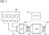
- Fig. 1 is a schematic configuration view showing an example of an exhaust system of a diesel engine (hereinafter, simply referred to as engine) 100, to which a first PM sensor 10A and a second PM sensor 10B according to the first embodiment are applied.
- an oxidation catalyst 210, a diesel particulate filter (DPF, hereinafter, simply also referred to as filter) 220 and the like are provided in this order from an upstream side in an exhaust direction.
- DPF diesel particulate filter
- the oxidation catalyst 210 is configured to oxidize unburned fuel (hydrocarbon (HC)) and to increase a temperature of the exhaust gas when the unburned fuel is supplied thereto.
- the filter 220 is formed so that a plurality of cells divided by porous partition walls are arranged along exhaust gas flow direction and are alternately plugged at upstream and downstream sides of the cells.
- the filter 220 is configured so that PM in the exhaust gas is collected by micro-holes or surfaces of the partition walls and if an estimated amount of PM accumulated thereon reaches a predetermined amount, a so-called filter forced regeneration of combusting and removing the PM accumulated thereon is executed.
- the filter forced regeneration is performed, for example, by supplying unburned fuel to the oxidation catalyst 210 upstream of the filter 220 and thus increasing a temperature of the exhaust gas to be introduced into the filter 220 to a PM combustion temperature.
- the first PM sensor 10A is provided in the exhaust pipe 110 upstream of the filter 220 in the exhaust direction, more specifically in the exhaust pipe 110 between the oxidation catalyst 210 and the filter 220 and is configured to detect an amount of PM contained in the exhaust gas to be introduced into the filter 220.
- the second PM sensor 10B is provided in the exhaust pipe 110 downstream of the filter 220 in the exhaust direction, more specifically in the exhaust pipe 110 immediately after the filter 220 and is configured to detect an amount of PM contained in the exhaust gas discharged from the filter 220.
- the first PM sensor 10A and the second PM sensor 10B have the same structure. Accordingly, in the following description, the PM sensors 10A, 10B will be collectively referred as PM sensor 10.
- the word 'first' is attached to the beginning of the term thereof and a symbol 'A' is attached to the end.
- the word 'second' is attached to the beginning of the term thereof and a symbol 'B' is attached to the end.
- the PM sensor 10 (first PM sensor 10A, second PM sensor 10B) includes a case member 11 (first case member 11A, second case member 11B) inserted in the exhaust pipe 110, a pedestal portion 20 (first pedestal portion 20A, second pedestal portion 20B) configured to attach the case member 11 to the exhaust pipe 110, a sensor unit 30 (first sensor unit 30A, second sensor unit 30B) accommodated in the case member 11 and a control unit 40.
- the case member 11 has a shape of a bottomed cylinder, of which a bottom side (a lower end side in the shown example) is closed.
- a length L of the case member 11 in a cylinder axis direction is substantially the same as a radius R of the exhaust pipe 110 so that a cylindrical wall portion at the bottom side protrudes to a location near to a center axis CL of the exhaust pipe 110.
- the bottom side of the case member 11 is referred to as a distal end side, and an opposite side to the bottom side is referred to as a base end side of the case member 11.
- a cylindrical wall portion of the case member 11 at the distal end side is provided with a plurality of inflow ports 12 (first inflow port 12A, second inflow port 12B) arranged to be spaced from each other in a circumferential direction.
- a cylindrical wall portion of the case member 11 at the base end side is provided with a plurality of outflow ports 13 (first outflow port 13A, second outflow port 13B) arranged to be spaced from each other in the circumferential direction.
- a total opening area S 12 of the inflow ports 12 is smaller than a total opening area S 13 of the outflow ports 13 (S 12 ⁇ S 13 ).
- an exhaust flow velocity V 12 in the vicinity of the inflow ports 12 becomes slower than an exhaust flow velocity V 13 in the vicinity of the outflow ports 13 (V 12 ⁇ V 13 ), so that a pressure P 12 at the inflow ports 12 becomes higher than a pressure P 13 at the outflow ports 13 (P 12 > P 13 ).
- the exhaust gas smoothly flows into the case member 11 through the inflow ports 12, and the exhaust gas in the case member 11 smoothly flows out through the outflow ports 13 into the exhaust pipe 110.
- the pedestal portion 20 has a male screw portion 21 (first male screw portion 21A, second male screw portion 21B) and a nut portion 22 (first nut portion 22A, second nut portion 22B).
- the male screw portion 21 is provided on a base end portion of the case member 11 and is configured to close an opening of the case member 11 at the base end side.
- the male screw portion 21 is screwed with a female screw portion of a boss portion 110A formed on the exhaust pipe 110.
- the nut portion 22 is, for example, a hexagonal nut and is fixed to an upper end portion of the male screw portion 21.
- the male screw portion 21 and the nut portion 22 have through-holes (not shown) formed therein, through which conductive wires 35, 36 (first conductive wires 35A, 36A, second conductive wires 35B, 36B) and the like as described below are to be inserted.
- the sensor unit 30 (first sensor unit 30A, second sensor unit 30B) has a sensor filter 31 (first sensor filter 31A, second sensor filter 31B), a plurality of pairs of electrodes 32, 33 (first pairs of electrodes 32A, 33A, second pairs of electrodes 32B, 33B) and an electrical heater 34 (first electrical heater 34A, second electrical heater 34B).
- the sensor filter 31 is formed so that a plurality of cells, which form lattice-shaped exhaust flow paths divided by partition walls of, for example, porous ceramics, are alternately plugged at upstream and downstream sides thereof.
- the sensor filter 31 is held on an inner peripheral surface of the case member 11 via a cushion member CM in a state where a flow path direction of the cells is arranged to be substantially parallel to an axial direction (an upward and downward direction in the figure) of the case member 11.
- PM 300 in the exhaust gas introduced in the case member 11 through the inflow ports 12 is collected by surfaces or micro-holes of partition walls as the exhaust gas flows from cells C1 (C1A, C1B) plugged at the downstream side thereof into cells C2 (C2A, C2B) plugged at the upstream side thereof as shown by broken line arrows.
- the cell plugged at the downstream side thereof is referred to as a measurement cell C1 (first measurement cell C1A, second measurement cell C1B) and the cell plugged at the upstream side thereof is referred to as an electrode cell C2 (first electrode cell C2A, second electrode cell C2B).
- the electrodes 32, 33 are, for example, conductive metal wires and are alternately inserted into the electrode cells C2 (first electrode cell C2A, second electrode cell C2B), which face each other with the measurement cell C1 interposed therebetween, from the downstream sides (unplugged side) thereof, thereby forming a capacitor.
- the electrodes 32, 33 are respectively connected to an electrostatic capacitance detection circuit (not shown) embedded in the control unit 40, via the conductive wires 35, 36 (first conductive wires 35A, 36A, second conductive wires 35B, 36B).
- the electrical heater 34 is, for example, an electric heating wire and is configured to generate heat by being energized and thus to directly heat the sensor filter 31, thereby executing a so-called filter regeneration of combusting and removing the PM accumulated in the measurement cells C1. Accordingly, the electrical heater 34 is formed to be bent into a continuous S-shape, and linear portions thereof parallel to each other are inserted in the respective measurement cells C1 along the flow paths thereof.
- the control unit 40 has a filter regeneration control unit 41, a first PM amount estimating calculation unit 42, a second PM amount estimating calculation unit 43 and a filter state determination unit 44 as individual functional elements.
- the functional elements are described as being contained in the control unit 40, which is a unitary hardware, but may be provided in separate hardware.
- the filter regeneration control unit 41 is an example of the filter regeneration means of the present invention and is configured to determine whether or not a filter regeneration condition is satisfied, based on an electrostatic capacitance Cp between the electrodes 32, 33, which is detected by an electrostatic capacitance detection circuit (not shown), and then to execute filter regeneration control of turning on (energizing) the electrical heater 34 in a case where the filter regeneration condition is satisfied.
- the electrostatic capacitance Cp between the electrodes 32, 33 is expressed by the following equation 1, where ⁇ is a dielectric constant of a medium between the electrodes 32, 33, S is a surface area of the electrodes 32, 33 and d is a distance between the electrodes 32, 33.
- Cp ⁇ ⁇ ⁇ s d
- the surface area S of the electrodes 32, 33 is constant, and when the dielectric constant ⁇ and the distance d are changed by the PM collected in the measurement cells C1, the electrostatic capacitance Cp is correspondingly changed. That is, the electrostatic capacitance Cp between the electrodes 32, 33 and an amount of the PM accumulated in the sensor filter 31 have a proportional relation.
- the filter regeneration control unit 41 determines that the filter regeneration condition is satisfied and thus starts filter regeneration of turning on the respective electrical heaters 34A, 34B. The filter regeneration continues until the respective electrostatic capacitances Cp A , Cp B are lowered to
- the first PM sensor 10A is arranged upstream of the filter 220 in the exhaust direction and the second PM sensor 10B is arranged downstream of the filter 220 in the exhaust direction. Accordingly, when the filter 220 is collecting PM, the PM is accumulated earlier in the first PM sensor 10A than in the second PM sensor 10B, and thus the first electrostatic capacitance Cp A reaches the upper threshold C P_max first.
- the first PM amount estimating calculation unit 42 estimates a total PM amount m PM_A in the exhaust gas, which is to be introduced into the filter 220, based on an electrostatic capacitance change amount ⁇ Cp A of the first PM sensor 10A during a regeneration interval period (from the end of the filter regeneration to the start of the next filter regeneration).
- the PM amount m PM_A collected in the first sensor filter 31A during the regeneration interval period is obtained by the following equation 2, in which the electrostatic capacitance change amount ⁇ Cp A of the first PM sensor 10A is multiplied by a linear coefficient ⁇ .
- m PM _ A ⁇ ⁇ ⁇ C p A
- the second PM amount estimating calculation unit 43 estimates a total PM amount m PM_B in the exhaust gas, which is discharged from the filter 220, based on an electrostatic capacitance change amount ⁇ Cp B of the second PM sensor 10B during the regeneration interval period.
- the PM amount m PM_B collected in the second sensor filter 31B during the regeneration interval period is obtained by the following equation 3, in which the electrostatic capacitance change amount ⁇ Cp B of the second PM sensor 10B is multiplied by a linear coefficient ⁇ .
- m PM _ B ⁇ ⁇ ⁇ C p B
- the filter state determination unit 44 is an example of the acquisition means of the present invention and is configured to acquire in real time a PM collecting efficiency of the filter 220, based on the electrostatic capacitance change amount ⁇ Cp A of the first PM sensor 10A during the regeneration interval period and the electrostatic capacitance change amount ⁇ Cp B of the second PM sensor 10B during the regeneration interval period, thereby determining a state of the filter 220.
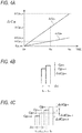
- the electrostatic capacitance change amount ⁇ Cp A of the first PM sensor 10A at a time t 0 is the electrostatic capacitance lower threshold C P_min . Thereafter, the electrostatic capacitance change amount ⁇ Cp A is increased over time and thus becomes ⁇ Cp A_tn at a time t n and ⁇ Cp A_tm at a time t m .
- the electrostatic capacitance change amount ⁇ Cp B of the second PM sensor 10B at a time t 0 is the electrostatic capacitance lower threshold C P_min . Thereafter, the electrostatic capacitance change amount ⁇ Cp B is increased over time and thus becomes ⁇ Cp B_tn at a time t n and ⁇ Cp B_tm at a time t m .
- the electrostatic capacitance change amount ⁇ Cp A has a gradient (increment per unit time) greater than that of the electrostatic capacitance change amount ⁇ Cp B .
- the reason is that an object to be detected by the second PM sensor 10B is the exhaust gas after being purified in the filter 220, whereas an object to be detected by the first PM sensor 10A is the exhaust gas before being purified in the filter 220.
- the filter state determination unit 44 monitors in real time the electrostatic capacitance change amount ⁇ Cp A of the first PM sensor 10A and the electrostatic capacitance change amount ⁇ Cp B of the second PM sensor 10B, and determines a state of the filter 220 based on the electrostatic capacitance change amount ⁇ Cp A and the electrostatic capacitance change amount ⁇ Cp B .
- the filter state determination unit 44 acquires as a PM collecting efficiency of the filter 220 a calculated value ⁇ Cp B / ⁇ Cp A obtained by dividing the electrostatic capacitance change amount ⁇ Cp B by the electrostatic capacitance change amount ⁇ Cp A .
- the calculated value ⁇ Cp B / ⁇ Cp A is a ratio of an amount of PM (integrated amount ⁇ Cp B ), which is discharged from the filter 220 without being collected therein, to an amount of PM (integrated amount ⁇ Cp A ) to be introduced into the filter 220 during a period from the time to to a determination time (the latest time) and thus can refer to the collecting efficiency.
- the filter state determination unit 44 is configured to determine that a PM collecting ability of the filter 220 has been degraded due to abnormality when the calculated value ⁇ Cp B / ⁇ Cp A is equal to or greater than a predetermined determination threshold.
- the determination threshold is previously obtained by an experiment or the like and then stored in a memory (not shown) of ECU 40.
- the filter state determination unit 44 is configured to calculate in real time a difference between the calculated value ⁇ Cp B / ⁇ Cp A and the determination threshold and then to determine whether or not an abnormal tendency exists, based on a time-series change of the difference. For example, if the calculated value ⁇ Cp B / ⁇ Cp A and the determination threshold are decreased over time and the difference becomes equal to or lower than a determination threshold for the difference, the filter state determination unit 44 determines that there is a possibility that an abnormality will occur in the filter 220.
- the filter state determination unit 44 can acquire a PM collecting efficiency of the filter 220 based on the first electrostatic capacitance Cp A of the first pair of electrodes 32A, 33A and the second electrostatic capacitance Cp B of the second pair of electrodes 32B, 33B, thereby acquiring in real time the PM collecting efficiency. Therefore, it is possible to determine in real time an abnormal degradation in PM collecting ability of the filter 220 or a tendency of the PM collecting ability to degrade (abnormal tendency).
- the first PM sensor 10A is provided upstream of the filter 220 in the exhaust direction. Therefore, it is possible to recognize an amount of PM to be introduced into the filter 220 with high accuracy. That is, although the amount of PM to be introduced into the filter 220 can be estimated from an operating state of the engine 100, properties of fuel and the like, if the amount is corrected by the quality of fuel, it is difficult to guarantee accuracy and the like. In this regard, in the present embodiment, determination with high accuracy can be made, since the first PM sensor 10A is provided.
- the total PM amount m PM_A in the exhaust gas to be introduced into the filter 220, the total PM amount m PM_B in the exhaust gas discharged from the filter 220 and the PM collecting efficiency of the filter 220 are acquired based on the first electrostatic capacitance Cp A (electrostatic capacitance change amount ⁇ Cp A ) and the second electrostatic capacitance Cp B (electrostatic capacitance change amount ⁇ Cp B )
- the ECU 40 acquires output signals from the first PM sensor 10A and the second PM sensor 10B at short repetition periods, at which the signals can be regarded as real time signals, thereby acquiring the first electrostatic capacitance Cp A , the second electrostatic capacitance Cp B and the like.
- a change rate (change amount per unit time ⁇ dCp/ ⁇ t) of the respective electrostatic capacitances Cp A , Cp B may be calculated from a plurality of first electrostatic capacitances Cp A and second electrostatic capacitances Cp B including the latest first electrostatic capacitance Cp A and the latest second electrostatic capacitance Cp B , respectively, and then the PM collecting efficiency of the filter 200 may be acquired based on the change rate of the respective electrostatic capacitances Cp A , CP B .
- the change rate ⁇ dCp m / ⁇ t is calculated from the latest respective electrostatic capacitances CP m (Cp A_m , Cp B_m ) and respective electrostatic capacitances CP m-1 (Cp A_m-1 , Cp B_m-1 ) one period before.
- CP m Cp A_m , Cp B_m
- CP m-1 Cp A_m-1 , Cp B_m-1
- the change rate ( ⁇ dCp m + ⁇ dCp m-1 + ⁇ dCp m-2 )/3 ⁇ t is calculated from the latest respective electrostatic capacitances CP m , respective electrostatic capacitances CP m-1 one period before, respective electrostatic capacitances CP m-2 two periods before and respective electrostatic capacitances CP m-1 three periods before. That is, a filtering process is performed.
- an PM amount m PM corresponding to the change rate ⁇ dCp A_m / ⁇ t or the change rate ⁇ dCp B_m / ⁇ t can be acquired using a map representing a relationship between the change rate ⁇ dCp _m / ⁇ t and the PM amount m PM , which is previously obtained by, for example, an experiment or the like.
- control for reducing a discharged amount of PM can be performed in real time with high accuracy.
- control for decreasing a circulation amount of EGR, increasing an excess air ratio, reducing an injection amount of fuel, or adjusting an injection timing of fuel can be performed in real time with high accuracy.
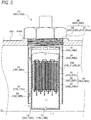
- PM sensor 10 (first PM sensor 10C, second PM sensor 10D) according to the second embodiment will be described in detail with reference to Fig. 5 .
- the PM sensor 10 (10C, 10D) of the second embodiment is configured so that the case member in the PM sensor 10 (10A, 10B) of the first embodiment has a double pipe structure.
- the other components have the same structures, and accordingly the detailed descriptions thereof will be omitted. Also, some components, such as the control unit 40 and the like, are not shown.
- the case member of the second embodiment has a cylindrical bottomed inner case portion 11 (11C, 11D) and a cylindrical outer case portion 15 (15C, 15D) surrounding a cylindrical outer peripheral surface of the inner case portion 11.
- the inner case portion 11 is formed to have an axial length greater than that of the outer case portion 15 so that a distal end side thereof protrudes relative to the outer case portion 15. Also, a bottom portion of the inner case portion 11 is provided with an outflow port 13 (13C, 13D) for allowing exhaust gas in the inner case portion 15 to flow into an exhaust pipe 110. Further, a cylindrical wall portion of the inner case portion 11 at a base end side thereof is provided with a plurality of passage ports 14 (14C, 14D) arranged to be spaced with each other in a circumferential direction. The passage ports 14 are configured to allow exhaust gas in a flow path 16 (16C, 16D) defined between an outer peripheral surface of the inner case portion 11 and an inner peripheral surface of the outer case portion 15 to flow into the inner case portion 11.
- a circular ring-shaped inflow port 12 (12C, 12D) defined between the cylindrical wall portion of the inner case portion 11 at the distal end side thereof and the distal end portion of the outer case portion 15 is formed on a downstream end of the flow path 16.
- An opening area S 12 of the inflow port 12 is formed to be smaller than an opening area S 13 of the outflow port 13 (S 12 ⁇ S 13 ).
- the exhaust gas flowing through the exhaust pipe 110 collides with the cylindrical wall surface of the inner case portion 11 protruding distally relative to the outer case portion 15 and thus is smoothly introduced into the flow path 16 through the inflow port 12 arranged near to a center axis CL of the exhaust pipe 110. Then, the exhaust gas flowing through the flow path 16 is introduced into the inner case portion 11 through the passage ports 14, passes through the sensor filter 31 (31C, 31D), and then smoothly flows out through the outflow port 13 arranged near to the center axis CL of the exhaust pipe 110 into the exhaust pipe 110.
- the inflow port 12 and the outflow port 13 are arranged near to the center axis CL where an exhaust flow velocity is highest in the exhaust pipe 110, so that it is possible to effectively increase a flow rate of the exhaust gas passing through the sensor filter 31.
- the PM sensor of the third embodiment is configured so that the sensor unit 30 (30A, 30B) of the first embodiment is a stack type.
- the other components have the same structures, and accordingly the detailed descriptions and illustrations thereof will be omitted.
- Fig. 6A is a perspective view of the sensor unit 60 (60A, 60B) of the third embodiment and Fig. 6B is an exploded perspective view of the sensor unit 60.
- the sensor unit 60 has a plurality of filter layers 61 (61A, 61B) and a plurality of electrode plates 62 (62A, 62B) and electrode plates 63 (63A, 63B).
- the filter layer 61 is formed so that a plurality of cells, which are divided by partition walls of, for example, porous ceramics or the like and form exhaust flow paths, are alternately plugged at upstream and downstream sides thereof and the cells are arranged in parallel in one direction in a cuboid shape.
- PM contained in the exhaust gas is collected by surfaces or micro-holes of the partitions walls of the cells C11 as the exhaust gas flows from the cells C11 (C11A, C11B) plugged at the downstream side thereof into the cells C12 (C12A, C12B) plugged at the upstream side thereof as shown by broken line arrows in Fig. 6B .
- a flow path direction of the cells is referred to as a longitudinal direction (an arrow L in Fig. 6A ) of the sensor unit 60, and a direction perpendicular to the flow path direction of the cells is referred to as a width direction (an arrow W in Fig. 6A ) of the sensor unit 60.
- the pair of electrode plates 62, 63 are conductive members having, for example, a flat plate shape, and external dimensions thereof in the longitudinal direction L and the width direction W are substantially the same as those of the filter layer 61.
- the pair of electrode plates 62, 63 are alternately stacked with the filter layer 61 interposed therebetween and are respectively connected to an electrostatic capacitance detection circuit (not shown) embedded in the control unit 40 via conductive wires 64 (64A, 64B) and conductive wires 65 (65A, 65B).
- the pair of electrode plates 62, 63 are arranged to face each other and the filter layer 61 are interposed between the electrode plates 62, 63, so that the entire cells C11 form a capacitor.
- the entire cells C11 are configured as the capacitor due to the electrode plates 62, 63 having a flat plate shape, so that it is possible to effectively secure an electrode surface area S and to increase an absolute value of a detectable electrostatic capacitance.
- the distance d between the electrodes corresponds to a pitch of the cells and is uniform, so that it is possible to effectively suppress the non-uniformity of an initial electrostatic capacitance.
- a voltage may be directly applied to the electrode plates 62, 63 or a heater board or the like (not shown) may be provided between the filter layer 61 and the electrode plates 62, 63.
- the exhaust purification device of the present invention has the effect that it is possible to acquire a PM collecting efficiency in real time and thus is useful in that it is possible to recognize a tendency of the collecting efficiency to degrade before the filter is determined to have a failure.
Landscapes
- Engineering & Computer Science (AREA)
- Chemical & Material Sciences (AREA)
- Combustion & Propulsion (AREA)
- Mechanical Engineering (AREA)
- General Engineering & Computer Science (AREA)
- Health & Medical Sciences (AREA)
- General Health & Medical Sciences (AREA)
- Physics & Mathematics (AREA)
- Chemical Kinetics & Catalysis (AREA)
- Life Sciences & Earth Sciences (AREA)
- Analytical Chemistry (AREA)
- Biochemistry (AREA)
- Electrochemistry (AREA)
- General Physics & Mathematics (AREA)
- Immunology (AREA)
- Pathology (AREA)
- Processes For Solid Components From Exhaust (AREA)
- Exhaust Gas After Treatment (AREA)
- Investigating Or Analyzing Materials By The Use Of Electric Means (AREA)
Abstract
Description
- The present invention relates to an exhaust purification device for purifying exhaust gas by collecting particular matter (hereinafter, referred to as PM) contained in the exhaust gas.
- Exhaust purification devices for purifying exhaust gas discharged from an internal combustion engine by collecting PM contained in the exhaust gas by means of a filter are known. As the exhaust purification devices, a device is also known in which PM sensors are respectively arranged upstream and downstream of a filter in an exhaust direction, so that it is possible to determine whether or not the filter has a failure. For example, in an exhaust purification device described in
Patent Reference 1, resistance-type PM sensors, which can be regenerated by a heater, are respectively arranged upstream and downstream of a filter in an exhaust direction. An inflow PM amount to be introduced into the filter and an outflow PM amount discharged from the filter are acquired based on detection signals from the respective PM sensors, and also a collecting efficiency is obtained therefrom. Then, whether or not the filter has a failure is determined by comparing the collecting efficiency with a predetermined determination threshold. - Patent Reference 1:
JP-A-2012-149525 - However, with regard to the filter, it is preferable that it is possible to recognize a tendency of the collecting efficiency to degrade before the filter is determined to have a failure. The reason is that an action such as replacement or repair can be taken before failure. Accordingly, it is preferable to acquire the PM collecting efficiency in real time.
- An object of the disclosure is to provide an exhaust purification device in which it is possible to acquire a PM collecting efficiency in real time.
- An exhaust purification device according to the disclosure includes a filter provided in an exhaust system of an internal combustion engine and collecting particulate matter in exhaust gas; a first sensor provided upstream of the filter in an exhaust direction of the exhaust gas and including: a first sensor filter having a plurality of first cells divided by porous partition walls and collecting the particulate matter in the exhaust gas to be introduced into the filter; and at least one pair of first electrodes arranged to face each other with the first cell interposed therebetween so as to form a capacitor; a second sensor provided downstream of the filter in the exhaust direction of the exhaust gas and including: a second sensor filter having a plurality of second cells divided by porous partition walls and collecting the particulate matter in the exhaust gas discharged from the filter; and at least one pair of second electrodes arranged to face each other with the second cell interposed therebetween so as to form a capacitor; and acquisition means for acquiring an efficiency of collecting the particulate matter in the filter, based on a first electrostatic capacitance between the pair of first electrodes and a second electrostatic capacitance between the pair of second electrodes.
- Further, an exhaust purification system according to the disclosure includes a filter provided in exhaust gas passage of an internal combustion engine and collecting particulate matter in exhaust gas; a first sensor provided upstream of the filter in an exhaust direction of the exhaust gas and including: a first sensor filter having a plurality of first cells divided by porous partition walls and collecting the particulate matter in the exhaust gas to be introduced into the filter; and at least one pair of first electrodes arranged to face each other with the first cell interposed therebetween so as to form a capacitor; a second sensor provided downstream of the filter in the exhaust direction of the exhaust gas and including: a second sensor filter having a plurality of second cells divided by porous partition walls and collecting the particulate matter in the exhaust gas discharged from the filter; and at least one pair of second electrodes arranged to face each other with the second cell interposed therebetween so as to form a capacitor; and a control unit, wherein the control unit is operated to execute t: an acquiring process of acquiring an efficiency of collecting the particulate matter in the filter, based on a first electrostatic capacitance between the pair of first electrodes and a second electrostatic capacitance between the pair of second electrodes.
- According to the exhaust purification device of the disclosure, it is possible to acquire a PM collecting efficiency of the filter in real time.
-
-
Fig. 1 is a schematic configuration view showing an example of an exhaust system to which a PM sensor of a first embodiment is applied. -
Fig. 2 is a schematic partially sectional view showing the PM sensor of the first embodiment. -
Fig. 3 is a partially enlarged sectional view explaining collecting of PM. -
Fig. 4A is a chart explaining a change over time in electrostatic capacitance change amount of a first PM sensor and a second PM sensor. -
Fig. 4B schematically illustrates a difference between electrostatic capacitances captured periodically. -
Fig. 4C schematically illustrates a difference between electrostatic capacitances captured periodically. -
Fig. 5 is a schematic partially sectional view showing a PM sensor of a second embodiment. -
Fig. 6A is a schematic perspective view of each of sensor units according to a third embodiment. -
Fig. 6B is a schematic exploded perspective view of each of sensor units according to the third embodiment. - Hereinafter, sensors according to respective embodiments of the disclosure will be described with reference to the accompanying drawings. The same components will be designated by the same reference numerals, and the names and functions thereof are the same. Therefore, the detailed descriptions thereof will not be repetitively made.
-
Fig. 1 is a schematic configuration view showing an example of an exhaust system of a diesel engine (hereinafter, simply referred to as engine) 100, to which afirst PM sensor 10A and asecond PM sensor 10B according to the first embodiment are applied. In anexhaust pipe 110 of theengine 100, anoxidation catalyst 210, a diesel particulate filter (DPF, hereinafter, simply also referred to as filter) 220 and the like are provided in this order from an upstream side in an exhaust direction. - The
oxidation catalyst 210 is configured to oxidize unburned fuel (hydrocarbon (HC)) and to increase a temperature of the exhaust gas when the unburned fuel is supplied thereto. Thefilter 220 is formed so that a plurality of cells divided by porous partition walls are arranged along exhaust gas flow direction and are alternately plugged at upstream and downstream sides of the cells. Thefilter 220 is configured so that PM in the exhaust gas is collected by micro-holes or surfaces of the partition walls and if an estimated amount of PM accumulated thereon reaches a predetermined amount, a so-called filter forced regeneration of combusting and removing the PM accumulated thereon is executed. The filter forced regeneration is performed, for example, by supplying unburned fuel to theoxidation catalyst 210 upstream of thefilter 220 and thus increasing a temperature of the exhaust gas to be introduced into thefilter 220 to a PM combustion temperature. - The
first PM sensor 10A is provided in theexhaust pipe 110 upstream of thefilter 220 in the exhaust direction, more specifically in theexhaust pipe 110 between theoxidation catalyst 210 and thefilter 220 and is configured to detect an amount of PM contained in the exhaust gas to be introduced into thefilter 220. Thesecond PM sensor 10B is provided in theexhaust pipe 110 downstream of thefilter 220 in the exhaust direction, more specifically in theexhaust pipe 110 immediately after thefilter 220 and is configured to detect an amount of PM contained in the exhaust gas discharged from thefilter 220. - Next, the detailed configurations of the
first PM sensor 10A and thesecond PM sensor 10B according to the first embodiment will be described with reference toFig. 2 . As shown inFig. 2 , thefirst PM sensor 10A and thesecond PM sensor 10B have the same structure. Accordingly, in the following description, thePM sensors PM sensor 10. In the description, for each of components equipped in thefirst PM sensor 10A, the word 'first' is attached to the beginning of the term thereof and a symbol 'A' is attached to the end. Also, for each of components equipped in thesecond PM sensor 10B, the word 'second' is attached to the beginning of the term thereof and a symbol 'B' is attached to the end. - The PM sensor 10 (
first PM sensor 10A,second PM sensor 10B) includes a case member 11 (first case member 11A,second case member 11B) inserted in theexhaust pipe 110, a pedestal portion 20 (first pedestal portion 20A,second pedestal portion 20B) configured to attach thecase member 11 to theexhaust pipe 110, a sensor unit 30 (first sensor unit 30A,second sensor unit 30B) accommodated in thecase member 11 and acontrol unit 40. - The
case member 11 has a shape of a bottomed cylinder, of which a bottom side (a lower end side in the shown example) is closed. A length L of thecase member 11 in a cylinder axis direction is substantially the same as a radius R of theexhaust pipe 110 so that a cylindrical wall portion at the bottom side protrudes to a location near to a center axis CL of theexhaust pipe 110. Here, in the following descriptions, the bottom side of thecase member 11 is referred to as a distal end side, and an opposite side to the bottom side is referred to as a base end side of thecase member 11. - A cylindrical wall portion of the
case member 11 at the distal end side is provided with a plurality of inflow ports 12 (first inflow port 12A,second inflow port 12B) arranged to be spaced from each other in a circumferential direction. Also, a cylindrical wall portion of thecase member 11 at the base end side is provided with a plurality of outflow ports 13 (first outflow port 13A,second outflow port 13B) arranged to be spaced from each other in the circumferential direction. A total opening area S12 of theinflow ports 12 is smaller than a total opening area S13 of the outflow ports 13 (S12 < S13). That is, an exhaust flow velocity V12 in the vicinity of theinflow ports 12 becomes slower than an exhaust flow velocity V13 in the vicinity of the outflow ports 13 (V12 < V13), so that a pressure P12 at theinflow ports 12 becomes higher than a pressure P13 at the outflow ports 13 (P12 > P13). Thus, the exhaust gas smoothly flows into thecase member 11 through theinflow ports 12, and the exhaust gas in thecase member 11 smoothly flows out through theoutflow ports 13 into theexhaust pipe 110. - The
pedestal portion 20 has a male screw portion 21 (firstmale screw portion 21A, secondmale screw portion 21B) and a nut portion 22 (first nut portion 22A,second nut portion 22B). Themale screw portion 21 is provided on a base end portion of thecase member 11 and is configured to close an opening of thecase member 11 at the base end side. Themale screw portion 21 is screwed with a female screw portion of aboss portion 110A formed on theexhaust pipe 110. Thenut portion 22 is, for example, a hexagonal nut and is fixed to an upper end portion of themale screw portion 21. Themale screw portion 21 and thenut portion 22 have through-holes (not shown) formed therein, through whichconductive wires 35, 36 (firstconductive wires conductive wires - The sensor unit 30 (
first sensor unit 30A,second sensor unit 30B) has a sensor filter 31 (first sensor filter 31A,second sensor filter 31B), a plurality of pairs ofelectrodes 32, 33 (first pairs ofelectrodes electrodes electrical heater 34A, secondelectrical heater 34B). - The
sensor filter 31 is formed so that a plurality of cells, which form lattice-shaped exhaust flow paths divided by partition walls of, for example, porous ceramics, are alternately plugged at upstream and downstream sides thereof. Thesensor filter 31 is held on an inner peripheral surface of thecase member 11 via a cushion member CM in a state where a flow path direction of the cells is arranged to be substantially parallel to an axial direction (an upward and downward direction in the figure) of thecase member 11. - As enlargedly shown in
Fig. 3 ,PM 300 in the exhaust gas introduced in thecase member 11 through theinflow ports 12 is collected by surfaces or micro-holes of partition walls as the exhaust gas flows from cells C1 (C1A, C1B) plugged at the downstream side thereof into cells C2 (C2A, C2B) plugged at the upstream side thereof as shown by broken line arrows. Meanwhile, in the following description, the cell plugged at the downstream side thereof is referred to as a measurement cell C1 (first measurement cell C1A, second measurement cell C1B) and the cell plugged at the upstream side thereof is referred to as an electrode cell C2 (first electrode cell C2A, second electrode cell C2B). - As shown in
Fig. 2 , theelectrodes electrodes control unit 40, via theconductive wires 35, 36 (firstconductive wires conductive wires - The
electrical heater 34 is, for example, an electric heating wire and is configured to generate heat by being energized and thus to directly heat thesensor filter 31, thereby executing a so-called filter regeneration of combusting and removing the PM accumulated in the measurement cells C1. Accordingly, theelectrical heater 34 is formed to be bent into a continuous S-shape, and linear portions thereof parallel to each other are inserted in the respective measurement cells C1 along the flow paths thereof. - The
control unit 40 has a filterregeneration control unit 41, a first PM amount estimatingcalculation unit 42, a second PM amount estimatingcalculation unit 43 and a filterstate determination unit 44 as individual functional elements. The functional elements are described as being contained in thecontrol unit 40, which is a unitary hardware, but may be provided in separate hardware. - The filter
regeneration control unit 41 is an example of the filter regeneration means of the present invention and is configured to determine whether or not a filter regeneration condition is satisfied, based on an electrostatic capacitance Cp between theelectrodes electrical heater 34 in a case where the filter regeneration condition is satisfied. The electrostatic capacitance Cp between theelectrodes following equation 1, where ε is a dielectric constant of a medium between theelectrodes electrodes electrodes 
- In the
equation 1, the surface area S of theelectrodes electrodes sensor filter 31 have a proportional relation. - If either one of a first electrostatic capacitance CpA between the first pair of
electrodes first PM sensor 10A, which is calculated based on a dielectric constant εA of a medium between the first pair ofelectrodes electrodes second PM sensor 10B, which is calculated based on a dielectric constant εB of a medium between the second pair ofelectrodes regeneration control unit 41 determines that the filter regeneration condition is satisfied and thus starts filter regeneration of turning on the respectiveelectrical heaters - Meanwhile, as shown in
Fig. 1 , in the present embodiment, thefirst PM sensor 10A is arranged upstream of thefilter 220 in the exhaust direction and thesecond PM sensor 10B is arranged downstream of thefilter 220 in the exhaust direction. Accordingly, when thefilter 220 is collecting PM, the PM is accumulated earlier in thefirst PM sensor 10A than in thesecond PM sensor 10B, and thus the first electrostatic capacitance CpA reaches the upper threshold CP_max first. - The first PM amount estimating
calculation unit 42 estimates a total PM amount mPM_A in the exhaust gas, which is to be introduced into thefilter 220, based on an electrostatic capacitance change amount ΔCpA of thefirst PM sensor 10A during a regeneration interval period (from the end of the filter regeneration to the start of the next filter regeneration). The PM amount mPM_A collected in thefirst sensor filter 31A during the regeneration interval period is obtained by thefollowing equation 2, in which the electrostatic capacitance change amount ΔCpA of thefirst PM sensor 10A is multiplied by a linear coefficient β.
- The second PM amount estimating
calculation unit 43 estimates a total PM amount mPM_B in the exhaust gas, which is discharged from thefilter 220, based on an electrostatic capacitance change amount ΔCpB of thesecond PM sensor 10B during the regeneration interval period. The PM amount mPM_B collected in thesecond sensor filter 31B during the regeneration interval period is obtained by thefollowing equation 3, in which the electrostatic capacitance change amount ΔCpB of thesecond PM sensor 10B is multiplied by a linear coefficient β.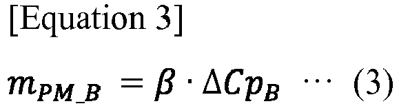
- The filter
state determination unit 44 is an example of the acquisition means of the present invention and is configured to acquire in real time a PM collecting efficiency of thefilter 220, based on the electrostatic capacitance change amount ΔCpA of thefirst PM sensor 10A during the regeneration interval period and the electrostatic capacitance change amount ΔCpB of thesecond PM sensor 10B during the regeneration interval period, thereby determining a state of thefilter 220. - In the example shown in
Fig. 4A , the electrostatic capacitance change amount ΔCpA of thefirst PM sensor 10A at a time t0 is the electrostatic capacitance lower threshold CP_min. Thereafter, the electrostatic capacitance change amount ΔCpA is increased over time and thus becomes ΔCpA_tn at a time tn and ΔCpA_tm at a time tm. Similarly, the electrostatic capacitance change amount ΔCpB of thesecond PM sensor 10B at a time t0 is the electrostatic capacitance lower threshold CP_min. Thereafter, the electrostatic capacitance change amount ΔCpB is increased over time and thus becomes ΔCpB_tn at a time tn and ΔCpB_tm at a time tm. - In comparison between the electrostatic capacitance change amount ΔCpA and the electrostatic capacitance change amount ΔCpB, the electrostatic capacitance change amount ΔCpA has a gradient (increment per unit time) greater than that of the electrostatic capacitance change amount ΔCpB. The reason is that an object to be detected by the
second PM sensor 10B is the exhaust gas after being purified in thefilter 220, whereas an object to be detected by thefirst PM sensor 10A is the exhaust gas before being purified in thefilter 220. - The filter
state determination unit 44 monitors in real time the electrostatic capacitance change amount ΔCpA of thefirst PM sensor 10A and the electrostatic capacitance change amount ΔCpB of thesecond PM sensor 10B, and determines a state of thefilter 220 based on the electrostatic capacitance change amount ΔCpA and the electrostatic capacitance change amount ΔCpB. - For example, the filter
state determination unit 44 acquires as a PM collecting efficiency of the filter 220 a calculated value ΔCpB/ΔCpA obtained by dividing the electrostatic capacitance change amount ΔCpB by the electrostatic capacitance change amount ΔCpA. The calculated value ΔCpB/ΔCpA is a ratio of an amount of PM (integrated amount ΔCpB), which is discharged from thefilter 220 without being collected therein, to an amount of PM (integrated amount ΔCpA) to be introduced into thefilter 220 during a period from the time to to a determination time (the latest time) and thus can refer to the collecting efficiency. The filterstate determination unit 44 is configured to determine that a PM collecting ability of thefilter 220 has been degraded due to abnormality when the calculated value ΔCpB/ΔCpA is equal to or greater than a predetermined determination threshold. The determination threshold is previously obtained by an experiment or the like and then stored in a memory (not shown) ofECU 40. - Further, the filter
state determination unit 44 is configured to calculate in real time a difference between the calculated value ΔCpB/ΔCpA and the determination threshold and then to determine whether or not an abnormal tendency exists, based on a time-series change of the difference. For example, if the calculated value ΔCpB/ΔCpA and the determination threshold are decreased over time and the difference becomes equal to or lower than a determination threshold for the difference, the filterstate determination unit 44 determines that there is a possibility that an abnormality will occur in thefilter 220. - As such, according to the present embodiment, the filter
state determination unit 44 can acquire a PM collecting efficiency of thefilter 220 based on the first electrostatic capacitance CpA of the first pair ofelectrodes electrodes filter 220 or a tendency of the PM collecting ability to degrade (abnormal tendency). - In addition, according to the present embodiment, the
first PM sensor 10A is provided upstream of thefilter 220 in the exhaust direction. Therefore, it is possible to recognize an amount of PM to be introduced into thefilter 220 with high accuracy. That is, although the amount of PM to be introduced into thefilter 220 can be estimated from an operating state of theengine 100, properties of fuel and the like, if the amount is corrected by the quality of fuel, it is difficult to guarantee accuracy and the like. In this regard, in the present embodiment, determination with high accuracy can be made, since thefirst PM sensor 10A is provided. - Meanwhile, in the embodiment as described above, the total PM amount mPM_A in the exhaust gas to be introduced into the
filter 220, the total PM amount mPM_B in the exhaust gas discharged from thefilter 220 and the PM collecting efficiency of thefilter 220 are acquired based on the first electrostatic capacitance CpA (electrostatic capacitance change amount ΔCpA) and the second electrostatic capacitance CpB (electrostatic capacitance change amount ΔCpB) - Herein, the
ECU 40 acquires output signals from thefirst PM sensor 10A and thesecond PM sensor 10B at short repetition periods, at which the signals can be regarded as real time signals, thereby acquiring the first electrostatic capacitance CpA, the second electrostatic capacitance CpB and the like. Accordingly, a change rate (change amount per unit time ΔdCp/Δt) of the respective electrostatic capacitances CpA, CpB may be calculated from a plurality of first electrostatic capacitances CpA and second electrostatic capacitances CpB including the latest first electrostatic capacitance CpA and the latest second electrostatic capacitance CpB, respectively, and then the PM collecting efficiency of the filter 200 may be acquired based on the change rate of the respective electrostatic capacitances CpA, CPB. - In the example of
Fig. 4B , the change rate ΔdCpm/Δt is calculated from the latest respective electrostatic capacitances CPm (CpA_m, CpB_m) and respective electrostatic capacitances CPm-1 (CpA_m-1, CpB_m-1) one period before. Similarly, in the example ofFig. 4C , the change rate (ΔdCpm + ΔdCpm-1 + ΔdCpm-2)/3Δt is calculated from the latest respective electrostatic capacitances CPm, respective electrostatic capacitances CPm-1 one period before, respective electrostatic capacitances CPm-2 two periods before and respective electrostatic capacitances CPm-1 three periods before. That is, a filtering process is performed. - In this way, by calculating the change rate ΔdCpA_m/Δt in the
first PM sensor 10A and the change rate ΔdCpB_m/Δt in thesecond PM sensor 10B, the latest instantaneous values on the total PM amount mPM_A in the exhaust gas to introduced into thefilter 220, the total PM amount mPM_B in the exhaust gas discharged from thefilter 220 and the PM collecting efficiency of thefilter 220 can be acquired. For the total PM amount mPM_A, the total PM amount mPM_B and the PM collecting efficiency, an PM amount mPM corresponding to the change rate ΔdCpA_m/Δt or the change rate ΔdCpB_m/Δt can be acquired using a map representing a relationship between the change rate ΔdCp_m/Δt and the PM amount mPM, which is previously obtained by, for example, an experiment or the like. - Further, by acquiring an average value of change rates of a plurality of periods as in
Fig. 4C , an influence of a noise suddenly generated can be reduced. - It is possible to perform control for reducing a discharged amount of PM as desired, based on the instantaneous values. For example, control for decreasing a circulation amount of EGR, increasing an excess air ratio, reducing an injection amount of fuel, or adjusting an injection timing of fuel can be performed in real time with high accuracy.
- Next, a PM sensor 10 (
first PM sensor 10C,second PM sensor 10D) according to the second embodiment will be described in detail with reference toFig. 5 . The PM sensor 10 (10C, 10D) of the second embodiment is configured so that the case member in the PM sensor 10 (10A, 10B) of the first embodiment has a double pipe structure. The other components have the same structures, and accordingly the detailed descriptions thereof will be omitted. Also, some components, such as thecontrol unit 40 and the like, are not shown. - The case member of the second embodiment has a cylindrical bottomed inner case portion 11 (11C, 11D) and a cylindrical outer case portion 15 (15C, 15D) surrounding a cylindrical outer peripheral surface of the
inner case portion 11. - The
inner case portion 11 is formed to have an axial length greater than that of the outer case portion 15 so that a distal end side thereof protrudes relative to the outer case portion 15. Also, a bottom portion of theinner case portion 11 is provided with an outflow port 13 (13C, 13D) for allowing exhaust gas in the inner case portion 15 to flow into anexhaust pipe 110. Further, a cylindrical wall portion of theinner case portion 11 at a base end side thereof is provided with a plurality of passage ports 14 (14C, 14D) arranged to be spaced with each other in a circumferential direction. Thepassage ports 14 are configured to allow exhaust gas in a flow path 16 (16C, 16D) defined between an outer peripheral surface of theinner case portion 11 and an inner peripheral surface of the outer case portion 15 to flow into theinner case portion 11. - On a downstream end of the
flow path 16, a circular ring-shaped inflow port 12 (12C, 12D) defined between the cylindrical wall portion of theinner case portion 11 at the distal end side thereof and the distal end portion of the outer case portion 15 is formed. An opening area S12 of theinflow port 12 is formed to be smaller than an opening area S13 of the outflow port 13 (S12 < S13). - That is, the exhaust gas flowing through the
exhaust pipe 110 collides with the cylindrical wall surface of theinner case portion 11 protruding distally relative to the outer case portion 15 and thus is smoothly introduced into theflow path 16 through theinflow port 12 arranged near to a center axis CL of theexhaust pipe 110. Then, the exhaust gas flowing through theflow path 16 is introduced into theinner case portion 11 through thepassage ports 14, passes through the sensor filter 31 (31C, 31D), and then smoothly flows out through theoutflow port 13 arranged near to the center axis CL of theexhaust pipe 110 into theexhaust pipe 110. As such, in thePM sensors inflow port 12 and theoutflow port 13 are arranged near to the center axis CL where an exhaust flow velocity is highest in theexhaust pipe 110, so that it is possible to effectively increase a flow rate of the exhaust gas passing through thesensor filter 31. - Next, a PM sensor according to the third embodiment will be described in detail with reference to
Fig. 6 . The PM sensor of the third embodiment is configured so that the sensor unit 30 (30A, 30B) of the first embodiment is a stack type. The other components have the same structures, and accordingly the detailed descriptions and illustrations thereof will be omitted. -
Fig. 6A is a perspective view of the sensor unit 60 (60A, 60B) of the third embodiment andFig. 6B is an exploded perspective view of thesensor unit 60. Thesensor unit 60 has a plurality of filter layers 61 (61A, 61B) and a plurality of electrode plates 62 (62A, 62B) and electrode plates 63 (63A, 63B). - The
filter layer 61 is formed so that a plurality of cells, which are divided by partition walls of, for example, porous ceramics or the like and form exhaust flow paths, are alternately plugged at upstream and downstream sides thereof and the cells are arranged in parallel in one direction in a cuboid shape. PM contained in the exhaust gas is collected by surfaces or micro-holes of the partitions walls of the cells C11 as the exhaust gas flows from the cells C11 (C11A, C11B) plugged at the downstream side thereof into the cells C12 (C12A, C12B) plugged at the upstream side thereof as shown by broken line arrows inFig. 6B . Meanwhile, in the following description, a flow path direction of the cells is referred to as a longitudinal direction (an arrow L inFig. 6A ) of thesensor unit 60, and a direction perpendicular to the flow path direction of the cells is referred to as a width direction (an arrow W inFig. 6A ) of thesensor unit 60. - The pair of
electrode plates filter layer 61. The pair ofelectrode plates filter layer 61 interposed therebetween and are respectively connected to an electrostatic capacitance detection circuit (not shown) embedded in thecontrol unit 40 via conductive wires 64 (64A, 64B) and conductive wires 65 (65A, 65B). - That is, the pair of
electrode plates filter layer 61 are interposed between theelectrode plates electrode plates - Meanwhile, when combusting and removing the PM accumulated in the cells C11, a voltage may be directly applied to the
electrode plates filter layer 61 and theelectrode plates - The present invention is not limited to the foregoing embodiments and changes thereof can be appropriately made without departing from the spirit and scope of the present invention.
- This application is based on Japanese Patent Application No.
2015-031526 filed on February 20, 2015 - The exhaust purification device of the present invention has the effect that it is possible to acquire a PM collecting efficiency in real time and thus is useful in that it is possible to recognize a tendency of the collecting efficiency to degrade before the filter is determined to have a failure.
-
- 10 (10A to 10D)
- PM sensor
- 11 (11A, 11B)
- Case member
- 11 (11C, 11D)
- Inner case portion
- 12 (12A to 12D)
- Inflow port
- 13 (13A to 13D)
- Outflow port
- 20 (20A to 20D)
- Pedestal portion
- 21 (21A to 21D)
- Male screw portion
- 22 (22A to 22D)
- Nut portion
- 30 (30A to 30D)
- Sensor unit
- 31 (31A to 31D)
- Sensor filter
- 32, 33 (32A to 32D, 33A to 33D)
- Pair of electrodes
- 34 (34A to 34D)
- Electrical heater
- 40
- Control unit
- 41
- Filter regeneration control unit
- 42
- First PM amount estimating calculation unit
- 43
- Second PM amount estimating calculation unit
- 44
- Filter state determination unit
Claims (8)
- An exhaust purification device comprising:a filter provided in an exhaust system of an internal combustion engine and collecting particulate matter in exhaust gas;a first sensor provided upstream of the filter in an exhaust direction of the exhaust gas and including: a first sensor filter having a plurality of first cells divided by porous partition walls and collecting the particulate matter in the exhaust gas to be introduced into the filter; and at least one pair of first electrodes arranged to face each other with the first cell interposed therebetween so as to form a capacitor;a second sensor provided downstream of the filter in the exhaust direction of the exhaust gas and including: a second sensor filter having a plurality of second cells divided by porous partition walls and collecting the particulate matter in the exhaust gas discharged from the filter; and at least one pair of second electrodes arranged to face each other with the second cell interposed therebetween so as to form a capacitor; andacquisition means for acquiring an efficiency of collecting the particulate matter in the filter, based on a first electrostatic capacitance between the pair of first electrodes and a second electrostatic capacitance between the pair of second electrodes.
- The exhaust purification device according to claim 1,
wherein the acquisition means acquires the first electrostatic capacitance and the second electrostatic capacitance at predetermined periods, calculates a first electrostatic capacitance change rate from a plurality of first electrostatic capacitances including the latest first electrostatic capacitance, calculates a second electrostatic capacitance change rate from a plurality of second electrostatic capacitances including the latest second electrostatic capacitance, and acquires the efficiency of collecting the particulate matter in the filter based on the first electrostatic capacitance change rate and the second electrostatic capacitance change rate. - The exhaust purification device according to claim 1 or 2,
wherein the first sensor includes a first heater configured to generate heat by being energized and thus to combust and remove the particulate matter accumulated on the first sensor filter,
wherein the second sensor includes a second heater configured to generate heat by being energized and thus to combust and remove the particulate matter accumulated on the second sensor filter, and
wherein the exhaust purification device further comprises filter regeneration means for combusting and removing both the particulate matter accumulated on the first sensor filter and the particulate matter accumulated on the second senor filter by energizing each of the first heater and the second heater in a case where a predetermined filter regeneration condition is satisfied. - The exhaust purification device according to claim 3,
wherein the first sensor filter is a first filter layer in which the plurality of first cells are arranged in parallel in one direction, and the second sensor filter is a second filter layer in which the plurality of second cells are arranged in parallel in one direction, and
wherein the pair of first electrodes is a pair of first flat plate-shaped electrodes arranged to face each other with the first filter layer interposed therebetween, and the pair of second electrodes is a pair of second flat plate-shaped electrodes arranged to face each other with the second filter layer interposed therebetween. - An exhaust purification device comprising:a filter provided in exhaust gas passage of an internal combustion engine and collecting particulate matter in exhaust gas;a first sensor provided upstream of the filter in an exhaust direction of the exhaust gas and including: a first sensor filter having a plurality of first cells divided by porous partition walls and collecting the particulate matter in the exhaust gas to be introduced into the filter; and at least one pair of first electrodes arranged to face each other with the first cell interposed therebetween so as to form a capacitor;a second sensor provided downstream of the filter in the exhaust direction of the exhaust gas and including: a second sensor filter having a plurality of second cells divided by porous partition walls and collecting the particulate matter in the exhaust gas discharged from the filter; and at least one pair of second electrodes arranged to face each other with the second cell interposed therebetween so as to form a capacitor; anda control unit;wherein the control unit is operated to execute:an acquiring process of acquiring an efficiency of collecting the particulate matter in the filter, based on a first electrostatic capacitance between the pair of first electrodes and a second electrostatic capacitance between the pair of second electrodes.
- The exhaust purification device according to claim 5,
wherein the acquiring process includes: acquiring the first electrostatic capacitance and the second electrostatic capacitance at predetermined periods, calculating a first electrostatic capacitance change rate from a plurality of first electrostatic capacitances including the latest first electrostatic capacitance, calculating a second electrostatic capacitance change rate from a plurality of second electrostatic capacitances including the latest second electrostatic capacitance, and acquiring the efficiency of collecting the particulate matter in the filter based on the first electrostatic capacitance change rate and the second electrostatic capacitance change rate. - The exhaust purification device according to claim 5 or 6,
wherein the first sensor includes a first heater configured to generate heat by being energized and thus to combust and remove the particulate matter accumulated on the first sensor filter,
wherein the second sensor includes a second heater configured to generate heat by being energized and thus to combust and remove the particulate matter accumulated on the second sensor filter, and
wherein the control unit is operated to further execute:a regenerating process of regenerating the filter by combusting and removing both the particulate matter accumulated on the first sensor filter and the particulate matter accumulated on the second senor filter by energizing each of the first heater and the second heater in a case where a predetermined filter regeneration condition is satisfied. - The exhaust purification device according to claim 7,
wherein the first sensor filter is a first filter layer in which the plurality of first cells are arranged in parallel in one direction, and the second sensor filter is a second filter layer in which the plurality of second cells are arranged in parallel in one direction, and
wherein the pair of first electrodes is a pair of first flat plate-shaped electrodes arranged to face each other with the first filter layer interposed therebetween, and the pair of second electrodes is a pair of second flat plate-shaped electrodes arranged to face each other with the second filter layer interposed therebetween.
Applications Claiming Priority (2)
| Application Number | Priority Date | Filing Date | Title |
|---|---|---|---|
| JP2015031526A JP2016153610A (en) | 2015-02-20 | 2015-02-20 | Exhaust emission control device |
| PCT/JP2016/054589 WO2016133127A1 (en) | 2015-02-20 | 2016-02-17 | Exhaust purification device |
Publications (3)
| Publication Number | Publication Date |
|---|---|
| EP3260673A1 true EP3260673A1 (en) | 2017-12-27 |
| EP3260673A4 EP3260673A4 (en) | 2018-08-01 |
| EP3260673B1 EP3260673B1 (en) | 2019-08-21 |
Family
ID=56692197
Family Applications (1)
| Application Number | Title | Priority Date | Filing Date |
|---|---|---|---|
| EP16752513.8A Active EP3260673B1 (en) | 2015-02-20 | 2016-02-17 | Exhaust purification device |
Country Status (5)
| Country | Link |
|---|---|
| US (1) | US10677123B2 (en) |
| EP (1) | EP3260673B1 (en) |
| JP (1) | JP2016153610A (en) |
| CN (1) | CN107250496B (en) |
| WO (1) | WO2016133127A1 (en) |
Families Citing this family (7)
| Publication number | Priority date | Publication date | Assignee | Title |
|---|---|---|---|---|
| JP6507497B2 (en) * | 2014-06-23 | 2019-05-08 | いすゞ自動車株式会社 | Sensor |
| DE102018114025A1 (en) * | 2018-06-12 | 2019-12-12 | Volkswagen Aktiengesellschaft | Exhaust after-treatment system and method for regeneration of a particulate filter |
| JP2020063928A (en) * | 2018-10-15 | 2020-04-23 | 京セラ株式会社 | Measurement apparatus, measurement system, measurement method, and measurement program |
| US11346264B2 (en) * | 2019-08-29 | 2022-05-31 | Cummins Emission Solutions Inc. | Systems and methods for controlling exhaust gas aftertreatment sensor systems |
| US11668215B2 (en) * | 2019-10-25 | 2023-06-06 | ECC TEC MSJ Incorporated | Catalytic converter |
| DE102020215291A1 (en) * | 2020-12-03 | 2022-06-09 | Robert Bosch Gesellschaft mit beschränkter Haftung | Method and computing unit for operating an internal combustion engine with a particle filter |
| CN112879124A (en) * | 2021-01-26 | 2021-06-01 | 东风汽车集团股份有限公司 | Automobile exhaust particulate matter adsorption equipment |
Family Cites Families (17)
| Publication number | Priority date | Publication date | Assignee | Title |
|---|---|---|---|---|
| JP2732031B2 (en) * | 1994-04-28 | 1998-03-25 | 株式会社いすゞセラミックス研究所 | Exhaust particulate filter for diesel engine |
| JP4186425B2 (en) * | 2001-03-26 | 2008-11-26 | いすゞ自動車株式会社 | Soot particle detection sensor, diesel particulate filter device using the same, and control method therefor |
| EP1566623B1 (en) * | 2004-02-06 | 2013-12-18 | C.R.F. Società Consortile per Azioni | Device for measuring the quantity of solid particles in a gas medium |
| US20080048681A1 (en) * | 2004-02-12 | 2008-02-28 | Daimlerchrysler Ag | Device for Determining the State of a Soot Particle Filter |
| DE102005016132A1 (en) * | 2005-04-08 | 2006-10-12 | Daimlerchrysler Ag | Exhaust system for internal combustion (IC) engine, makes particulate sensors on upstream side of particulate filter independently operable with respect to their reference conditions |
| JP2008063985A (en) * | 2006-09-06 | 2008-03-21 | Ngk Insulators Ltd | Honeycomb structure for fine particle sensor |
| JP4756068B2 (en) * | 2008-12-22 | 2011-08-24 | 本田技研工業株式会社 | Failure detection device for exhaust purification filter |
| DE102009007126A1 (en) * | 2009-02-02 | 2010-08-12 | Continental Automotive Gmbh | Method and apparatus for measuring soot loading in exhaust systems of diesel engines |
| JP5107973B2 (en) * | 2009-03-11 | 2012-12-26 | 本田技研工業株式会社 | Failure detection device for exhaust purification filter |
| US8438899B2 (en) * | 2009-09-02 | 2013-05-14 | Ford Global Technologies, Llc | Method for evaluating degradation of a particulate matter sensor |
| JP5344084B2 (en) * | 2010-03-26 | 2013-11-20 | トヨタ自動車株式会社 | Particulate filter failure detection apparatus and failure detection method |
| JP2012012960A (en) * | 2010-06-29 | 2012-01-19 | Nippon Soken Inc | Particulate matter detection sensor |
| JP5625812B2 (en) * | 2010-11-29 | 2014-11-19 | いすゞ自動車株式会社 | PM sensor and PM sensor manufacturing method |
| JP5115873B2 (en) * | 2010-12-08 | 2013-01-09 | 株式会社デンソー | Particulate filter failure detection device |
| JP5614295B2 (en) * | 2011-01-17 | 2014-10-29 | マツダ株式会社 | Engine exhaust purification system |
| JP2013160617A (en) * | 2012-02-03 | 2013-08-19 | Honda Motor Co Ltd | Particulate matter detection apparatus |
| US9151205B2 (en) * | 2013-02-15 | 2015-10-06 | Indiana University Research & Technology Corporation | Real-time soot measurement in a diesel particulate filter |
-
2015
- 2015-02-20 JP JP2015031526A patent/JP2016153610A/en active Pending
-
2016
- 2016-02-17 US US15/552,218 patent/US10677123B2/en active Active
- 2016-02-17 WO PCT/JP2016/054589 patent/WO2016133127A1/en not_active Ceased
- 2016-02-17 EP EP16752513.8A patent/EP3260673B1/en active Active
- 2016-02-17 CN CN201680010676.6A patent/CN107250496B/en active Active
Also Published As
| Publication number | Publication date |
|---|---|
| US20180038251A1 (en) | 2018-02-08 |
| CN107250496B (en) | 2019-11-15 |
| US10677123B2 (en) | 2020-06-09 |
| EP3260673A4 (en) | 2018-08-01 |
| CN107250496A (en) | 2017-10-13 |
| EP3260673B1 (en) | 2019-08-21 |
| WO2016133127A1 (en) | 2016-08-25 |
| JP2016153610A (en) | 2016-08-25 |
Similar Documents
| Publication | Publication Date | Title |
|---|---|---|
| EP3260673B1 (en) | Exhaust purification device | |
| EP3225800B1 (en) | Diagnostic device and sensor | |
| US10030567B2 (en) | Exhaust purification device | |
| JP6409452B2 (en) | Diagnostic equipment | |
| EP3159685B1 (en) | Sensor | |
| EP3181844B1 (en) | Sensor | |
| EP3260854A1 (en) | Sensor | |
| US10337434B2 (en) | Particulate matter (PM) sensor | |
| US10481061B2 (en) | Sensor for detecting an emission amount of particulate matter | |
| JP6405938B2 (en) | Diagnostic device and sensor | |
| JP6409436B2 (en) | Diagnostic equipment | |
| JP6451179B2 (en) | Diagnostic equipment | |
| JP2016108995A (en) | Sensor | |
| JP2017191050A (en) | Sensor |
Legal Events
| Date | Code | Title | Description |
|---|---|---|---|
| STAA | Information on the status of an ep patent application or granted ep patent |
Free format text: STATUS: THE INTERNATIONAL PUBLICATION HAS BEEN MADE |
|
| PUAI | Public reference made under article 153(3) epc to a published international application that has entered the european phase |
Free format text: ORIGINAL CODE: 0009012 |
|
| STAA | Information on the status of an ep patent application or granted ep patent |
Free format text: STATUS: REQUEST FOR EXAMINATION WAS MADE |
|
| 17P | Request for examination filed |
Effective date: 20170920 |
|
| AK | Designated contracting states |
Kind code of ref document: A1 Designated state(s): AL AT BE BG CH CY CZ DE DK EE ES FI FR GB GR HR HU IE IS IT LI LT LU LV MC MK MT NL NO PL PT RO RS SE SI SK SM TR |
|
| AX | Request for extension of the european patent |
Extension state: BA ME |
|
| DAV | Request for validation of the european patent (deleted) | ||
| DAX | Request for extension of the european patent (deleted) | ||
| A4 | Supplementary search report drawn up and despatched |
Effective date: 20180628 |
|
| RIC1 | Information provided on ipc code assigned before grant |
Ipc: F01N 3/00 20060101ALI20180622BHEP Ipc: F01N 3/20 20060101ALI20180622BHEP Ipc: F01N 3/023 20060101AFI20180622BHEP Ipc: F01N 9/00 20060101ALI20180622BHEP Ipc: G01N 27/22 20060101ALI20180622BHEP Ipc: F01N 3/025 20060101ALI20180622BHEP Ipc: F02D 41/00 20060101ALI20180622BHEP Ipc: F01N 3/10 20060101ALI20180622BHEP |
|
| GRAP | Despatch of communication of intention to grant a patent |
Free format text: ORIGINAL CODE: EPIDOSNIGR1 |
|
| STAA | Information on the status of an ep patent application or granted ep patent |
Free format text: STATUS: GRANT OF PATENT IS INTENDED |
|
| INTG | Intention to grant announced |
Effective date: 20190322 |
|
| GRAS | Grant fee paid |
Free format text: ORIGINAL CODE: EPIDOSNIGR3 |
|
| GRAA | (expected) grant |
Free format text: ORIGINAL CODE: 0009210 |
|
| STAA | Information on the status of an ep patent application or granted ep patent |
Free format text: STATUS: THE PATENT HAS BEEN GRANTED |
|
| AK | Designated contracting states |
Kind code of ref document: B1 Designated state(s): AL AT BE BG CH CY CZ DE DK EE ES FI FR GB GR HR HU IE IS IT LI LT LU LV MC MK MT NL NO PL PT RO RS SE SI SK SM TR |
|
| REG | Reference to a national code |
Ref country code: GB Ref legal event code: FG4D |
|
| REG | Reference to a national code |
Ref country code: CH Ref legal event code: EP |
|
| REG | Reference to a national code |
Ref country code: DE Ref legal event code: R096 Ref document number: 602016019074 Country of ref document: DE |
|
| REG | Reference to a national code |
Ref country code: AT Ref legal event code: REF Ref document number: 1170003 Country of ref document: AT Kind code of ref document: T Effective date: 20190915 |
|
| REG | Reference to a national code |
Ref country code: IE Ref legal event code: FG4D |
|
| REG | Reference to a national code |
Ref country code: LT Ref legal event code: MG4D |
|
| REG | Reference to a national code |
Ref country code: NL Ref legal event code: MP Effective date: 20190821 |
|
| PG25 | Lapsed in a contracting state [announced via postgrant information from national office to epo] |
Ref country code: PT Free format text: LAPSE BECAUSE OF FAILURE TO SUBMIT A TRANSLATION OF THE DESCRIPTION OR TO PAY THE FEE WITHIN THE PRESCRIBED TIME-LIMIT Effective date: 20191223 Ref country code: BG Free format text: LAPSE BECAUSE OF FAILURE TO SUBMIT A TRANSLATION OF THE DESCRIPTION OR TO PAY THE FEE WITHIN THE PRESCRIBED TIME-LIMIT Effective date: 20191121 Ref country code: SE Free format text: LAPSE BECAUSE OF FAILURE TO SUBMIT A TRANSLATION OF THE DESCRIPTION OR TO PAY THE FEE WITHIN THE PRESCRIBED TIME-LIMIT Effective date: 20190821 Ref country code: NO Free format text: LAPSE BECAUSE OF FAILURE TO SUBMIT A TRANSLATION OF THE DESCRIPTION OR TO PAY THE FEE WITHIN THE PRESCRIBED TIME-LIMIT Effective date: 20191121 Ref country code: FI Free format text: LAPSE BECAUSE OF FAILURE TO SUBMIT A TRANSLATION OF THE DESCRIPTION OR TO PAY THE FEE WITHIN THE PRESCRIBED TIME-LIMIT Effective date: 20190821 Ref country code: NL Free format text: LAPSE BECAUSE OF FAILURE TO SUBMIT A TRANSLATION OF THE DESCRIPTION OR TO PAY THE FEE WITHIN THE PRESCRIBED TIME-LIMIT Effective date: 20190821 Ref country code: LT Free format text: LAPSE BECAUSE OF FAILURE TO SUBMIT A TRANSLATION OF THE DESCRIPTION OR TO PAY THE FEE WITHIN THE PRESCRIBED TIME-LIMIT Effective date: 20190821 Ref country code: HR Free format text: LAPSE BECAUSE OF FAILURE TO SUBMIT A TRANSLATION OF THE DESCRIPTION OR TO PAY THE FEE WITHIN THE PRESCRIBED TIME-LIMIT Effective date: 20190821 |
|
| PG25 | Lapsed in a contracting state [announced via postgrant information from national office to epo] |
Ref country code: AL Free format text: LAPSE BECAUSE OF FAILURE TO SUBMIT A TRANSLATION OF THE DESCRIPTION OR TO PAY THE FEE WITHIN THE PRESCRIBED TIME-LIMIT Effective date: 20190821 Ref country code: ES Free format text: LAPSE BECAUSE OF FAILURE TO SUBMIT A TRANSLATION OF THE DESCRIPTION OR TO PAY THE FEE WITHIN THE PRESCRIBED TIME-LIMIT Effective date: 20190821 Ref country code: GR Free format text: LAPSE BECAUSE OF FAILURE TO SUBMIT A TRANSLATION OF THE DESCRIPTION OR TO PAY THE FEE WITHIN THE PRESCRIBED TIME-LIMIT Effective date: 20191122 Ref country code: LV Free format text: LAPSE BECAUSE OF FAILURE TO SUBMIT A TRANSLATION OF THE DESCRIPTION OR TO PAY THE FEE WITHIN THE PRESCRIBED TIME-LIMIT Effective date: 20190821 Ref country code: RS Free format text: LAPSE BECAUSE OF FAILURE TO SUBMIT A TRANSLATION OF THE DESCRIPTION OR TO PAY THE FEE WITHIN THE PRESCRIBED TIME-LIMIT Effective date: 20190821 Ref country code: IS Free format text: LAPSE BECAUSE OF FAILURE TO SUBMIT A TRANSLATION OF THE DESCRIPTION OR TO PAY THE FEE WITHIN THE PRESCRIBED TIME-LIMIT Effective date: 20191221 |
|
| REG | Reference to a national code |
Ref country code: AT Ref legal event code: MK05 Ref document number: 1170003 Country of ref document: AT Kind code of ref document: T Effective date: 20190821 |
|
| PG25 | Lapsed in a contracting state [announced via postgrant information from national office to epo] |
Ref country code: TR Free format text: LAPSE BECAUSE OF FAILURE TO SUBMIT A TRANSLATION OF THE DESCRIPTION OR TO PAY THE FEE WITHIN THE PRESCRIBED TIME-LIMIT Effective date: 20190821 |
|
| PG25 | Lapsed in a contracting state [announced via postgrant information from national office to epo] |
Ref country code: EE Free format text: LAPSE BECAUSE OF FAILURE TO SUBMIT A TRANSLATION OF THE DESCRIPTION OR TO PAY THE FEE WITHIN THE PRESCRIBED TIME-LIMIT Effective date: 20190821 Ref country code: PL Free format text: LAPSE BECAUSE OF FAILURE TO SUBMIT A TRANSLATION OF THE DESCRIPTION OR TO PAY THE FEE WITHIN THE PRESCRIBED TIME-LIMIT Effective date: 20190821 Ref country code: DK Free format text: LAPSE BECAUSE OF FAILURE TO SUBMIT A TRANSLATION OF THE DESCRIPTION OR TO PAY THE FEE WITHIN THE PRESCRIBED TIME-LIMIT Effective date: 20190821 Ref country code: IT Free format text: LAPSE BECAUSE OF FAILURE TO SUBMIT A TRANSLATION OF THE DESCRIPTION OR TO PAY THE FEE WITHIN THE PRESCRIBED TIME-LIMIT Effective date: 20190821 Ref country code: RO Free format text: LAPSE BECAUSE OF FAILURE TO SUBMIT A TRANSLATION OF THE DESCRIPTION OR TO PAY THE FEE WITHIN THE PRESCRIBED TIME-LIMIT Effective date: 20190821 Ref country code: AT Free format text: LAPSE BECAUSE OF FAILURE TO SUBMIT A TRANSLATION OF THE DESCRIPTION OR TO PAY THE FEE WITHIN THE PRESCRIBED TIME-LIMIT Effective date: 20190821 |
|
| PG25 | Lapsed in a contracting state [announced via postgrant information from national office to epo] |
Ref country code: IS Free format text: LAPSE BECAUSE OF FAILURE TO SUBMIT A TRANSLATION OF THE DESCRIPTION OR TO PAY THE FEE WITHIN THE PRESCRIBED TIME-LIMIT Effective date: 20200224 Ref country code: CZ Free format text: LAPSE BECAUSE OF FAILURE TO SUBMIT A TRANSLATION OF THE DESCRIPTION OR TO PAY THE FEE WITHIN THE PRESCRIBED TIME-LIMIT Effective date: 20190821 Ref country code: SM Free format text: LAPSE BECAUSE OF FAILURE TO SUBMIT A TRANSLATION OF THE DESCRIPTION OR TO PAY THE FEE WITHIN THE PRESCRIBED TIME-LIMIT Effective date: 20190821 Ref country code: SK Free format text: LAPSE BECAUSE OF FAILURE TO SUBMIT A TRANSLATION OF THE DESCRIPTION OR TO PAY THE FEE WITHIN THE PRESCRIBED TIME-LIMIT Effective date: 20190821 |
|
| REG | Reference to a national code |
Ref country code: DE Ref legal event code: R097 Ref document number: 602016019074 Country of ref document: DE |
|
| PLBE | No opposition filed within time limit |
Free format text: ORIGINAL CODE: 0009261 |
|
| STAA | Information on the status of an ep patent application or granted ep patent |
Free format text: STATUS: NO OPPOSITION FILED WITHIN TIME LIMIT |
|
| PG2D | Information on lapse in contracting state deleted |
Ref country code: IS |
|
| 26N | No opposition filed |
Effective date: 20200603 |
|
| PG25 | Lapsed in a contracting state [announced via postgrant information from national office to epo] |
Ref country code: SI Free format text: LAPSE BECAUSE OF FAILURE TO SUBMIT A TRANSLATION OF THE DESCRIPTION OR TO PAY THE FEE WITHIN THE PRESCRIBED TIME-LIMIT Effective date: 20190821 |
|
| REG | Reference to a national code |
Ref country code: CH Ref legal event code: PL |
|
| REG | Reference to a national code |
Ref country code: BE Ref legal event code: MM Effective date: 20200229 |
|
| PG25 | Lapsed in a contracting state [announced via postgrant information from national office to epo] |
Ref country code: LU Free format text: LAPSE BECAUSE OF NON-PAYMENT OF DUE FEES Effective date: 20200217 Ref country code: MC Free format text: LAPSE BECAUSE OF FAILURE TO SUBMIT A TRANSLATION OF THE DESCRIPTION OR TO PAY THE FEE WITHIN THE PRESCRIBED TIME-LIMIT Effective date: 20190821 |
|
| PG25 | Lapsed in a contracting state [announced via postgrant information from national office to epo] |
Ref country code: CH Free format text: LAPSE BECAUSE OF NON-PAYMENT OF DUE FEES Effective date: 20200229 Ref country code: LI Free format text: LAPSE BECAUSE OF NON-PAYMENT OF DUE FEES Effective date: 20200229 |
|
| PG25 | Lapsed in a contracting state [announced via postgrant information from national office to epo] |
Ref country code: IE Free format text: LAPSE BECAUSE OF NON-PAYMENT OF DUE FEES Effective date: 20200217 |
|
| PG25 | Lapsed in a contracting state [announced via postgrant information from national office to epo] |
Ref country code: BE Free format text: LAPSE BECAUSE OF NON-PAYMENT OF DUE FEES Effective date: 20200229 |
|
| PG25 | Lapsed in a contracting state [announced via postgrant information from national office to epo] |
Ref country code: MT Free format text: LAPSE BECAUSE OF FAILURE TO SUBMIT A TRANSLATION OF THE DESCRIPTION OR TO PAY THE FEE WITHIN THE PRESCRIBED TIME-LIMIT Effective date: 20190821 Ref country code: CY Free format text: LAPSE BECAUSE OF FAILURE TO SUBMIT A TRANSLATION OF THE DESCRIPTION OR TO PAY THE FEE WITHIN THE PRESCRIBED TIME-LIMIT Effective date: 20190821 |
|
| PG25 | Lapsed in a contracting state [announced via postgrant information from national office to epo] |
Ref country code: MK Free format text: LAPSE BECAUSE OF FAILURE TO SUBMIT A TRANSLATION OF THE DESCRIPTION OR TO PAY THE FEE WITHIN THE PRESCRIBED TIME-LIMIT Effective date: 20190821 |
|
| PGFP | Annual fee paid to national office [announced via postgrant information from national office to epo] |
Ref country code: GB Payment date: 20221230 Year of fee payment: 8 |
|
| PGFP | Annual fee paid to national office [announced via postgrant information from national office to epo] |
Ref country code: FR Payment date: 20230110 Year of fee payment: 8 |
|
| REG | Reference to a national code |
Ref country code: DE Ref legal event code: R082 Ref document number: 602016019074 Country of ref document: DE Representative=s name: MEISSNER BOLTE PATENTANWAELTE RECHTSANWAELTE P, DE |
|
| GBPC | Gb: european patent ceased through non-payment of renewal fee |
Effective date: 20240217 |
|
| PG25 | Lapsed in a contracting state [announced via postgrant information from national office to epo] |
Ref country code: GB Free format text: LAPSE BECAUSE OF NON-PAYMENT OF DUE FEES Effective date: 20240217 |
|
| PG25 | Lapsed in a contracting state [announced via postgrant information from national office to epo] |
Ref country code: FR Free format text: LAPSE BECAUSE OF NON-PAYMENT OF DUE FEES Effective date: 20240229 |
|
| PG25 | Lapsed in a contracting state [announced via postgrant information from national office to epo] |
Ref country code: GB Free format text: LAPSE BECAUSE OF NON-PAYMENT OF DUE FEES Effective date: 20240217 Ref country code: FR Free format text: LAPSE BECAUSE OF NON-PAYMENT OF DUE FEES Effective date: 20240229 |
|
| PGFP | Annual fee paid to national office [announced via postgrant information from national office to epo] |
Ref country code: DE Payment date: 20260121 Year of fee payment: 11 |