EP3260418A1 - Production system and production method for nitrogen-containing products and products selected from fermented/cultured products - Google Patents
Production system and production method for nitrogen-containing products and products selected from fermented/cultured products Download PDFInfo
- Publication number
- EP3260418A1 EP3260418A1 EP16752519.5A EP16752519A EP3260418A1 EP 3260418 A1 EP3260418 A1 EP 3260418A1 EP 16752519 A EP16752519 A EP 16752519A EP 3260418 A1 EP3260418 A1 EP 3260418A1
- Authority
- EP
- European Patent Office
- Prior art keywords
- ammonia
- gas
- product
- nitrogen
- production
- Prior art date
- Legal status (The legal status is an assumption and is not a legal conclusion. Google has not performed a legal analysis and makes no representation as to the accuracy of the status listed.)
- Granted
Links
- 0 *CC(CC1C*(*)*(*)CC1)C(C1)C1(CC1)CC(C*)[C@@]1C(*)*1CC1 Chemical compound *CC(CC1C*(*)*(*)CC1)C(C1)C1(CC1)CC(C*)[C@@]1C(*)*1CC1 0.000 description 7
- GDOPTJXRTPNYNR-UHFFFAOYSA-N CC1CCCC1 Chemical compound CC1CCCC1 GDOPTJXRTPNYNR-UHFFFAOYSA-N 0.000 description 1
- BUDWXZVWUARELI-UHFFFAOYSA-N CCCC(CCC1)CC1C1CC1 Chemical compound CCCC(CCC1)CC1C1CC1 BUDWXZVWUARELI-UHFFFAOYSA-N 0.000 description 1
Images



Classifications
-
- C—CHEMISTRY; METALLURGY
- C01—INORGANIC CHEMISTRY
- C01B—NON-METALLIC ELEMENTS; COMPOUNDS THEREOF; METALLOIDS OR COMPOUNDS THEREOF NOT COVERED BY SUBCLASS C01C
- C01B21/00—Nitrogen; Compounds thereof
- C01B21/20—Nitrogen oxides; Oxyacids of nitrogen; Salts thereof
- C01B21/38—Nitric acid
-
- C—CHEMISTRY; METALLURGY
- C12—BIOCHEMISTRY; BEER; SPIRITS; WINE; VINEGAR; MICROBIOLOGY; ENZYMOLOGY; MUTATION OR GENETIC ENGINEERING
- C12P—FERMENTATION OR ENZYME-USING PROCESSES TO SYNTHESISE A DESIRED CHEMICAL COMPOUND OR COMPOSITION OR TO SEPARATE OPTICAL ISOMERS FROM A RACEMIC MIXTURE
- C12P13/00—Preparation of nitrogen-containing organic compounds
- C12P13/04—Alpha- or beta- amino acids
- C12P13/08—Lysine; Diaminopimelic acid; Threonine; Valine
-
- B—PERFORMING OPERATIONS; TRANSPORTING
- B01—PHYSICAL OR CHEMICAL PROCESSES OR APPARATUS IN GENERAL
- B01D—SEPARATION
- B01D53/00—Separation of gases or vapours; Recovering vapours of volatile solvents from gases; Chemical or biological purification of waste gases, e.g. engine exhaust gases, smoke, fumes, flue gases, aerosols
- B01D53/22—Separation of gases or vapours; Recovering vapours of volatile solvents from gases; Chemical or biological purification of waste gases, e.g. engine exhaust gases, smoke, fumes, flue gases, aerosols by diffusion
- B01D53/229—Integrated processes (Diffusion and at least one other process, e.g. adsorption, absorption)
-
- B—PERFORMING OPERATIONS; TRANSPORTING
- B01—PHYSICAL OR CHEMICAL PROCESSES OR APPARATUS IN GENERAL
- B01J—CHEMICAL OR PHYSICAL PROCESSES, e.g. CATALYSIS OR COLLOID CHEMISTRY; THEIR RELEVANT APPARATUS
- B01J19/00—Chemical, physical or physico-chemical processes in general; Their relevant apparatus
- B01J19/0006—Controlling or regulating processes
-
- B—PERFORMING OPERATIONS; TRANSPORTING
- B01—PHYSICAL OR CHEMICAL PROCESSES OR APPARATUS IN GENERAL
- B01J—CHEMICAL OR PHYSICAL PROCESSES, e.g. CATALYSIS OR COLLOID CHEMISTRY; THEIR RELEVANT APPARATUS
- B01J21/00—Catalysts comprising the elements, oxides, or hydroxides of magnesium, boron, aluminium, carbon, silicon, titanium, zirconium, or hafnium
- B01J21/06—Silicon, titanium, zirconium or hafnium; Oxides or hydroxides thereof
- B01J21/066—Zirconium or hafnium; Oxides or hydroxides thereof
-
- B—PERFORMING OPERATIONS; TRANSPORTING
- B01—PHYSICAL OR CHEMICAL PROCESSES OR APPARATUS IN GENERAL
- B01J—CHEMICAL OR PHYSICAL PROCESSES, e.g. CATALYSIS OR COLLOID CHEMISTRY; THEIR RELEVANT APPARATUS
- B01J23/00—Catalysts comprising metals or metal oxides or hydroxides, not provided for in group B01J21/00
- B01J23/02—Catalysts comprising metals or metal oxides or hydroxides, not provided for in group B01J21/00 of the alkali- or alkaline earth metals or beryllium
-
- B—PERFORMING OPERATIONS; TRANSPORTING
- B01—PHYSICAL OR CHEMICAL PROCESSES OR APPARATUS IN GENERAL
- B01J—CHEMICAL OR PHYSICAL PROCESSES, e.g. CATALYSIS OR COLLOID CHEMISTRY; THEIR RELEVANT APPARATUS
- B01J23/00—Catalysts comprising metals or metal oxides or hydroxides, not provided for in group B01J21/00
- B01J23/38—Catalysts comprising metals or metal oxides or hydroxides, not provided for in group B01J21/00 of noble metals
- B01J23/40—Catalysts comprising metals or metal oxides or hydroxides, not provided for in group B01J21/00 of noble metals of the platinum group metals
- B01J23/46—Ruthenium, rhodium, osmium or iridium
- B01J23/462—Ruthenium
-
- B—PERFORMING OPERATIONS; TRANSPORTING
- B01—PHYSICAL OR CHEMICAL PROCESSES OR APPARATUS IN GENERAL
- B01J—CHEMICAL OR PHYSICAL PROCESSES, e.g. CATALYSIS OR COLLOID CHEMISTRY; THEIR RELEVANT APPARATUS
- B01J27/00—Catalysts comprising the elements or compounds of halogens, sulfur, selenium, tellurium, phosphorus or nitrogen; Catalysts comprising carbon compounds
- B01J27/24—Nitrogen compounds
-
- B—PERFORMING OPERATIONS; TRANSPORTING
- B01—PHYSICAL OR CHEMICAL PROCESSES OR APPARATUS IN GENERAL
- B01J—CHEMICAL OR PHYSICAL PROCESSES, e.g. CATALYSIS OR COLLOID CHEMISTRY; THEIR RELEVANT APPARATUS
- B01J35/00—Catalysts, in general, characterised by their form or physical properties
- B01J35/19—Catalysts containing parts with different compositions
-
- B—PERFORMING OPERATIONS; TRANSPORTING
- B01—PHYSICAL OR CHEMICAL PROCESSES OR APPARATUS IN GENERAL
- B01J—CHEMICAL OR PHYSICAL PROCESSES, e.g. CATALYSIS OR COLLOID CHEMISTRY; THEIR RELEVANT APPARATUS
- B01J37/00—Processes, in general, for preparing catalysts; Processes, in general, for activation of catalysts
- B01J37/04—Mixing
-
- B—PERFORMING OPERATIONS; TRANSPORTING
- B01—PHYSICAL OR CHEMICAL PROCESSES OR APPARATUS IN GENERAL
- B01J—CHEMICAL OR PHYSICAL PROCESSES, e.g. CATALYSIS OR COLLOID CHEMISTRY; THEIR RELEVANT APPARATUS
- B01J37/00—Processes, in general, for preparing catalysts; Processes, in general, for activation of catalysts
- B01J37/08—Heat treatment
- B01J37/082—Decomposition and pyrolysis
- B01J37/088—Decomposition of a metal salt
-
- B—PERFORMING OPERATIONS; TRANSPORTING
- B01—PHYSICAL OR CHEMICAL PROCESSES OR APPARATUS IN GENERAL
- B01J—CHEMICAL OR PHYSICAL PROCESSES, e.g. CATALYSIS OR COLLOID CHEMISTRY; THEIR RELEVANT APPARATUS
- B01J4/00—Feed or outlet devices; Feed or outlet control devices
- B01J4/001—Feed or outlet devices as such, e.g. feeding tubes
-
- B—PERFORMING OPERATIONS; TRANSPORTING
- B01—PHYSICAL OR CHEMICAL PROCESSES OR APPARATUS IN GENERAL
- B01J—CHEMICAL OR PHYSICAL PROCESSES, e.g. CATALYSIS OR COLLOID CHEMISTRY; THEIR RELEVANT APPARATUS
- B01J4/00—Feed or outlet devices; Feed or outlet control devices
- B01J4/008—Feed or outlet control devices
-
- C—CHEMISTRY; METALLURGY
- C01—INORGANIC CHEMISTRY
- C01C—AMMONIA; CYANOGEN; COMPOUNDS THEREOF
- C01C1/00—Ammonia; Compounds thereof
- C01C1/02—Preparation, purification or separation of ammonia
- C01C1/04—Preparation of ammonia by synthesis
- C01C1/0405—Preparation of ammonia by synthesis from N2 and H2 in presence of a catalyst
- C01C1/0411—Preparation of ammonia by synthesis from N2 and H2 in presence of a catalyst characterised by the catalyst
-
- C—CHEMISTRY; METALLURGY
- C01—INORGANIC CHEMISTRY
- C01C—AMMONIA; CYANOGEN; COMPOUNDS THEREOF
- C01C1/00—Ammonia; Compounds thereof
- C01C1/02—Preparation, purification or separation of ammonia
- C01C1/04—Preparation of ammonia by synthesis
- C01C1/0405—Preparation of ammonia by synthesis from N2 and H2 in presence of a catalyst
- C01C1/0417—Preparation of ammonia by synthesis from N2 and H2 in presence of a catalyst characterised by the synthesis reactor, e.g. arrangement of catalyst beds and heat exchangers in the reactor
-
- C—CHEMISTRY; METALLURGY
- C01—INORGANIC CHEMISTRY
- C01C—AMMONIA; CYANOGEN; COMPOUNDS THEREOF
- C01C1/00—Ammonia; Compounds thereof
- C01C1/02—Preparation, purification or separation of ammonia
- C01C1/04—Preparation of ammonia by synthesis
- C01C1/0405—Preparation of ammonia by synthesis from N2 and H2 in presence of a catalyst
- C01C1/0488—Processes integrated with preparations of other compounds, e.g. methanol, urea or with processes for power generation
-
- C—CHEMISTRY; METALLURGY
- C01—INORGANIC CHEMISTRY
- C01C—AMMONIA; CYANOGEN; COMPOUNDS THEREOF
- C01C1/00—Ammonia; Compounds thereof
- C01C1/18—Nitrates of ammonium
- C01C1/185—Preparation
-
- C—CHEMISTRY; METALLURGY
- C01—INORGANIC CHEMISTRY
- C01C—AMMONIA; CYANOGEN; COMPOUNDS THEREOF
- C01C1/00—Ammonia; Compounds thereof
- C01C1/28—Methods of preparing ammonium salts in general
-
- C—CHEMISTRY; METALLURGY
- C07—ORGANIC CHEMISTRY
- C07C—ACYCLIC OR CARBOCYCLIC COMPOUNDS
- C07C273/00—Preparation of urea or its derivatives, i.e. compounds containing any of the groups, the nitrogen atoms not being part of nitro or nitroso groups
- C07C273/02—Preparation of urea or its derivatives, i.e. compounds containing any of the groups, the nitrogen atoms not being part of nitro or nitroso groups of urea, its salts, complexes or addition compounds
-
- C—CHEMISTRY; METALLURGY
- C12—BIOCHEMISTRY; BEER; SPIRITS; WINE; VINEGAR; MICROBIOLOGY; ENZYMOLOGY; MUTATION OR GENETIC ENGINEERING
- C12M—APPARATUS FOR ENZYMOLOGY OR MICROBIOLOGY; APPARATUS FOR CULTURING MICROORGANISMS FOR PRODUCING BIOMASS, FOR GROWING CELLS OR FOR OBTAINING FERMENTATION OR METABOLIC PRODUCTS, i.e. BIOREACTORS OR FERMENTERS
- C12M1/00—Apparatus for enzymology or microbiology
-
- C—CHEMISTRY; METALLURGY
- C12—BIOCHEMISTRY; BEER; SPIRITS; WINE; VINEGAR; MICROBIOLOGY; ENZYMOLOGY; MUTATION OR GENETIC ENGINEERING
- C12M—APPARATUS FOR ENZYMOLOGY OR MICROBIOLOGY; APPARATUS FOR CULTURING MICROORGANISMS FOR PRODUCING BIOMASS, FOR GROWING CELLS OR FOR OBTAINING FERMENTATION OR METABOLIC PRODUCTS, i.e. BIOREACTORS OR FERMENTERS
- C12M29/00—Means for introduction, extraction or recirculation of materials, e.g. pumps
- C12M29/26—Conditioning fluids entering or exiting the reaction vessel
-
- C—CHEMISTRY; METALLURGY
- C12—BIOCHEMISTRY; BEER; SPIRITS; WINE; VINEGAR; MICROBIOLOGY; ENZYMOLOGY; MUTATION OR GENETIC ENGINEERING
- C12N—MICROORGANISMS OR ENZYMES; COMPOSITIONS THEREOF; PROPAGATING, PRESERVING, OR MAINTAINING MICROORGANISMS; MUTATION OR GENETIC ENGINEERING; CULTURE MEDIA
- C12N1/00—Microorganisms; Compositions thereof; Processes of propagating, maintaining or preserving microorganisms or compositions thereof; Processes of preparing or isolating a composition containing a microorganism; Culture media therefor
-
- C—CHEMISTRY; METALLURGY
- C12—BIOCHEMISTRY; BEER; SPIRITS; WINE; VINEGAR; MICROBIOLOGY; ENZYMOLOGY; MUTATION OR GENETIC ENGINEERING
- C12P—FERMENTATION OR ENZYME-USING PROCESSES TO SYNTHESISE A DESIRED CHEMICAL COMPOUND OR COMPOSITION OR TO SEPARATE OPTICAL ISOMERS FROM A RACEMIC MIXTURE
- C12P1/00—Preparation of compounds or compositions, not provided for in groups C12P3/00 - C12P39/00, by using microorganisms or enzymes
-
- C—CHEMISTRY; METALLURGY
- C12—BIOCHEMISTRY; BEER; SPIRITS; WINE; VINEGAR; MICROBIOLOGY; ENZYMOLOGY; MUTATION OR GENETIC ENGINEERING
- C12P—FERMENTATION OR ENZYME-USING PROCESSES TO SYNTHESISE A DESIRED CHEMICAL COMPOUND OR COMPOSITION OR TO SEPARATE OPTICAL ISOMERS FROM A RACEMIC MIXTURE
- C12P13/00—Preparation of nitrogen-containing organic compounds
- C12P13/04—Alpha- or beta- amino acids
-
- C—CHEMISTRY; METALLURGY
- C12—BIOCHEMISTRY; BEER; SPIRITS; WINE; VINEGAR; MICROBIOLOGY; ENZYMOLOGY; MUTATION OR GENETIC ENGINEERING
- C12P—FERMENTATION OR ENZYME-USING PROCESSES TO SYNTHESISE A DESIRED CHEMICAL COMPOUND OR COMPOSITION OR TO SEPARATE OPTICAL ISOMERS FROM A RACEMIC MIXTURE
- C12P13/00—Preparation of nitrogen-containing organic compounds
- C12P13/04—Alpha- or beta- amino acids
- C12P13/14—Glutamic acid; Glutamine
-
- C—CHEMISTRY; METALLURGY
- C12—BIOCHEMISTRY; BEER; SPIRITS; WINE; VINEGAR; MICROBIOLOGY; ENZYMOLOGY; MUTATION OR GENETIC ENGINEERING
- C12P—FERMENTATION OR ENZYME-USING PROCESSES TO SYNTHESISE A DESIRED CHEMICAL COMPOUND OR COMPOSITION OR TO SEPARATE OPTICAL ISOMERS FROM A RACEMIC MIXTURE
- C12P19/00—Preparation of compounds containing saccharide radicals
- C12P19/04—Polysaccharides, i.e. compounds containing more than five saccharide radicals attached to each other by glycosidic bonds
-
- C—CHEMISTRY; METALLURGY
- C12—BIOCHEMISTRY; BEER; SPIRITS; WINE; VINEGAR; MICROBIOLOGY; ENZYMOLOGY; MUTATION OR GENETIC ENGINEERING
- C12P—FERMENTATION OR ENZYME-USING PROCESSES TO SYNTHESISE A DESIRED CHEMICAL COMPOUND OR COMPOSITION OR TO SEPARATE OPTICAL ISOMERS FROM A RACEMIC MIXTURE
- C12P21/00—Preparation of peptides or proteins
-
- C—CHEMISTRY; METALLURGY
- C12—BIOCHEMISTRY; BEER; SPIRITS; WINE; VINEGAR; MICROBIOLOGY; ENZYMOLOGY; MUTATION OR GENETIC ENGINEERING
- C12P—FERMENTATION OR ENZYME-USING PROCESSES TO SYNTHESISE A DESIRED CHEMICAL COMPOUND OR COMPOSITION OR TO SEPARATE OPTICAL ISOMERS FROM A RACEMIC MIXTURE
- C12P7/00—Preparation of oxygen-containing organic compounds
- C12P7/02—Preparation of oxygen-containing organic compounds containing a hydroxy group
-
- C—CHEMISTRY; METALLURGY
- C12—BIOCHEMISTRY; BEER; SPIRITS; WINE; VINEGAR; MICROBIOLOGY; ENZYMOLOGY; MUTATION OR GENETIC ENGINEERING
- C12P—FERMENTATION OR ENZYME-USING PROCESSES TO SYNTHESISE A DESIRED CHEMICAL COMPOUND OR COMPOSITION OR TO SEPARATE OPTICAL ISOMERS FROM A RACEMIC MIXTURE
- C12P7/00—Preparation of oxygen-containing organic compounds
- C12P7/40—Preparation of oxygen-containing organic compounds containing a carboxyl group including Peroxycarboxylic acids
-
- B—PERFORMING OPERATIONS; TRANSPORTING
- B01—PHYSICAL OR CHEMICAL PROCESSES OR APPARATUS IN GENERAL
- B01J—CHEMICAL OR PHYSICAL PROCESSES, e.g. CATALYSIS OR COLLOID CHEMISTRY; THEIR RELEVANT APPARATUS
- B01J2204/00—Aspects relating to feed or outlet devices; Regulating devices for feed or outlet devices
- B01J2204/002—Aspects relating to feed or outlet devices; Regulating devices for feed or outlet devices the feeding side being of particular interest
-
- B—PERFORMING OPERATIONS; TRANSPORTING
- B01—PHYSICAL OR CHEMICAL PROCESSES OR APPARATUS IN GENERAL
- B01J—CHEMICAL OR PHYSICAL PROCESSES, e.g. CATALYSIS OR COLLOID CHEMISTRY; THEIR RELEVANT APPARATUS
- B01J2204/00—Aspects relating to feed or outlet devices; Regulating devices for feed or outlet devices
- B01J2204/005—Aspects relating to feed or outlet devices; Regulating devices for feed or outlet devices the outlet side being of particular interest
-
- B—PERFORMING OPERATIONS; TRANSPORTING
- B01—PHYSICAL OR CHEMICAL PROCESSES OR APPARATUS IN GENERAL
- B01J—CHEMICAL OR PHYSICAL PROCESSES, e.g. CATALYSIS OR COLLOID CHEMISTRY; THEIR RELEVANT APPARATUS
- B01J2219/00—Chemical, physical or physico-chemical processes in general; Their relevant apparatus
- B01J2219/00002—Chemical plants
- B01J2219/00004—Scale aspects
- B01J2219/00006—Large-scale industrial plants
-
- B—PERFORMING OPERATIONS; TRANSPORTING
- B01—PHYSICAL OR CHEMICAL PROCESSES OR APPARATUS IN GENERAL
- B01J—CHEMICAL OR PHYSICAL PROCESSES, e.g. CATALYSIS OR COLLOID CHEMISTRY; THEIR RELEVANT APPARATUS
- B01J2219/00—Chemical, physical or physico-chemical processes in general; Their relevant apparatus
- B01J2219/00002—Chemical plants
- B01J2219/00027—Process aspects
- B01J2219/0004—Processes in series
-
- C—CHEMISTRY; METALLURGY
- C12—BIOCHEMISTRY; BEER; SPIRITS; WINE; VINEGAR; MICROBIOLOGY; ENZYMOLOGY; MUTATION OR GENETIC ENGINEERING
- C12R—INDEXING SCHEME ASSOCIATED WITH SUBCLASSES C12C - C12Q, RELATING TO MICROORGANISMS
- C12R2001/00—Microorganisms ; Processes using microorganisms
- C12R2001/01—Bacteria or Actinomycetales ; using bacteria or Actinomycetales
- C12R2001/185—Escherichia
- C12R2001/19—Escherichia coli
-
- C—CHEMISTRY; METALLURGY
- C12—BIOCHEMISTRY; BEER; SPIRITS; WINE; VINEGAR; MICROBIOLOGY; ENZYMOLOGY; MUTATION OR GENETIC ENGINEERING
- C12R—INDEXING SCHEME ASSOCIATED WITH SUBCLASSES C12C - C12Q, RELATING TO MICROORGANISMS
- C12R2001/00—Microorganisms ; Processes using microorganisms
- C12R2001/01—Bacteria or Actinomycetales ; using bacteria or Actinomycetales
- C12R2001/265—Micrococcus
- C12R2001/28—Micrococcus glutamicus ; Corynebacterium glutamicum
-
- Y—GENERAL TAGGING OF NEW TECHNOLOGICAL DEVELOPMENTS; GENERAL TAGGING OF CROSS-SECTIONAL TECHNOLOGIES SPANNING OVER SEVERAL SECTIONS OF THE IPC; TECHNICAL SUBJECTS COVERED BY FORMER USPC CROSS-REFERENCE ART COLLECTIONS [XRACs] AND DIGESTS
- Y02—TECHNOLOGIES OR APPLICATIONS FOR MITIGATION OR ADAPTATION AGAINST CLIMATE CHANGE
- Y02P—CLIMATE CHANGE MITIGATION TECHNOLOGIES IN THE PRODUCTION OR PROCESSING OF GOODS
- Y02P20/00—Technologies relating to chemical industry
- Y02P20/10—Process efficiency
- Y02P20/129—Energy recovery, e.g. by cogeneration, H2recovery or pressure recovery turbines
-
- Y—GENERAL TAGGING OF NEW TECHNOLOGICAL DEVELOPMENTS; GENERAL TAGGING OF CROSS-SECTIONAL TECHNOLOGIES SPANNING OVER SEVERAL SECTIONS OF THE IPC; TECHNICAL SUBJECTS COVERED BY FORMER USPC CROSS-REFERENCE ART COLLECTIONS [XRACs] AND DIGESTS
- Y02—TECHNOLOGIES OR APPLICATIONS FOR MITIGATION OR ADAPTATION AGAINST CLIMATE CHANGE
- Y02P—CLIMATE CHANGE MITIGATION TECHNOLOGIES IN THE PRODUCTION OR PROCESSING OF GOODS
- Y02P20/00—Technologies relating to chemical industry
- Y02P20/50—Improvements relating to the production of bulk chemicals
- Y02P20/52—Improvements relating to the production of bulk chemicals using catalysts, e.g. selective catalysts
Definitions
- the present invention relates to a production system and a method of production for a product selected from a nitrogen-containing product and a fermented and cultured product.
- Ammonia has a wide variety of uses such as raw materials of various kinds of nitrogen-containing products, a nitrogen source in fermentation and culture and a pH adjuster.
- a large-scale production process by the Haber-Bosch process As an industrial production process for ammonia, a large-scale production process by the Haber-Bosch process is known.
- a source gas containing hydrogen and nitrogen reacts under a high-temperature, high-pressure condition at 400°C to 600°C and 20 MPa to 100 MPa using a doubly promoted iron catalyst obtained by adding a few percent by weight of Al 2 O 3 and K 2 O to Fe 3 O 4 to synthesize ammonia.
- Patent Literature 1 and Non Patent Literature 1 and 2 disclose a technique in which a source gas containing hydrogen and nitrogen reacts in a low pressure condition using a supported metal catalyst in which a conductive mayenite compound supports active metals such as ruthenium to synthesize ammonia, for example.
- Non Patent Literature 3 Global demand for ammonia is increasing, and ammonia synthesis plants tend to upsize.
- Patent Literature 1 WO 2010/077658
- ammonia The synthesis of ammonia by a large-scale production process assumes that obtained ammonia is liquefied and stored and is transported as liquid ammonia to ammonia consumption sites (the production sites of ammonia-related products). In addition to the costs of ammonia synthesis itself, also required are costs associated with the storage and transport of liquid ammonia, and ammonia prices tend to be stuck at a high level.
- An object of the present invention is to provide a novel production system and a production method for a product selected from a nitrogen-containing product and a fermented and cultured product that do not involve (or can minimize) the transport of liquid ammonia.
- the present inventions are as follows.
- the present invention can provide a novel production system and a method of production for a product selected from a nitrogen-containing product and a fermented and cultured product.
- the production system and the method of production of the present invention do not involve (or can minimize) the transport of liquid ammonia and can thereby simplify and reduce peripheral equipment and costs associated with the storage, transport, and maintenance of liquid ammonia.
- the present invention provides a novel production system for ammonia-related products using ammonia in production.
- ammonia synthesis by a large-scale production system assumes that synthesized ammonia is liquefied and stored and is transported as liquid ammonia to ammonia consumption sites (the production sites of ammonia-related products), and peripheral costs associated with the storage, transport and maintenance of liquid ammonia have tended to increase.
- ammonia in an amount required for the production of the ammonia-related products is produced at the production sites of the ammonia-related products (that is, produced on site). With this production, the ammonia-related products can be produced without the storage and transport of liquid ammonia.
- the production system of the present invention is a production system for a product selected from a nitrogen-containing product and a fermented and cultured product including an ammonia synthesis apparatus, in which an ammonia-containing gas is synthesized by reaction of a source gas containing hydrogen and nitrogen in the presence of a supported metal catalyst containing as a support one or more selected from the group consisting of: i) a conductive mayenite compound; ii) a two-dimensional electride compound or a precursor thereof; and iii) a complex formed of a support base containing at least one metal oxide selected from ZrO 2 , TiO 2 , CeO 2 , and MgO and a metal amide represented by a formula M(NH 2 ) x (where M represents one or more selected from Li, Na, K, Be, Mg, Ca, Sr, Ba, and Eu; and x represents a valence number of M) supported by the support base; and a production apparatus that produces a product selected from a
- the "nitrogen-containing product” refers to products containing a nitrogen atom originating from ammonia.
- the nitrogen-containing product include, but are not limited to, ammonia water, ammonium salts, urea, nitric acid, and nitrates.
- the ammonium salts include inorganic ammonium salts such as ammonium sulfate, ammonium nitrate, and ammonium chloride; and organic ammonium salts such as ammonium formate, ammonium acetate, ammonium citrate, and alkyl ammonium compounds.
- the nitrates include potassium nitrate, sodium nitrate, and calcium nitrate.
- the "fermented and cultured product” refers to products in a fermentation and culture process with ammonia used as a nitrogen source or a pH adjuster.
- Examples of the fermented and cultured product include, but are not limited to, organic compounds such as amino acids, organic acids, polysaccharides, proteins, antibiotics, and alcohols and microbial cells.
- the ammonia-containing gas is synthesized by reaction of the source gas containing hydrogen and nitrogen in the presence of the supported metal catalyst containing as the support one or more selected from the group consisting of: i) the conductive mayenite compound; ii) the two-dimensional electride compound or the precursor thereof; and iii) the complex formed of the support base containing at least one metal oxide selected from ZrO 2 , TiO 2 , CeO 2 , and MgO and the metal amide represented by the formula M(NH 2 ) x (where M represents one or more selected from Li, Na, K, Be, Mg, Ca, Sr, Ba, and Eu; and x represents a valence number of M) supported by the support base.
- M represents one or more selected from Li, Na, K, Be, Mg, Ca, Sr, Ba, and Eu
- x represents a valence number of M
- the "conductive mayenite compound" used as the support of the supported metal catalyst is a mayenite compound containing conduction electrons.
- the mayenite compound refers to mayenite as a mineral itself, mayenite rocks, and complex oxides having the same crystal structure as that of a mineral mayenite crystal.
- the crystal of the mayenite compound is formed by basket-shaped structures (cages) with an inner diameter of about 0.4 nm that share their wall faces to be connected to each other in a three-dimensional manner.
- the cages of the mayenite compound normally contain negative ions such as O 2- , which can be replaced with conduction electrons by annealing. A longer annealing time increases conduction electron density within the mayenite compound.
- a representative composition of the conductive mayenite compound is represented by a formula [Ca 24 Al 28 O 64 ] 4+ (O 2- ) 2-x (e - ) 2x (0 ⁇ x ⁇ 2).
- the conduction electron density within the mayenite compound is preferably 10 15 cm -3 or higher, more preferably 10 16 cm -3 or higher, further preferably 10 17 cm -3 or higher, and further more preferably 10 18 cm -3 or higher.
- the upper limit of the conduction electron density which is not limited to a particular value, can be normally 2.2 ⁇ 10 21 cm -3 or lower, 2.0 ⁇ 10 21 cm -3 or lower, or the like.
- the conduction electron density within the mayenite compound can be measured by a method described in WO 2012/077658 , for example.
- part or the whole of Ca contained in the formula of representative composition may be replaced with one or more typical metal elements or transition metal elements selected from the group consisting of Li, Na, K, Mg, Sr, Ba, Sc, Ti, V, Cr, Mn, Fe, Co, Ni, Cu, Ir, Ru, Rh, and Pt.
- Part or the whole of Al contained in the representative composition may be replaced with one or more typical metal elements or transition metal elements selected from the group consisting of B, Ga, C, Si, Fe, and Ge.
- part or the whole of O contained in the formula of the representative composition may be replaced with one or more typical elements or transition elements selected from the group consisting of H, F, Cl, Br, and Au.
- the conductive mayenite compound can be prepared by a method described in WO 2012/077658 , for example.
- the conductive mayenite compound may be an electride of the conductive mayenite compound.
- Examples of such a conductive mayenite compound include an electride of a mixed oxide of calcium and aluminum (an electride of 12CaO ⁇ 7Al 2 O 3 ) .
- the "two-dimensional electride compound" used as the support of the supported metal catalyst refers to a layered compound in which electrons are present as negative ions between layers, that is, an electride in which the layers are connected via the electrons present between the layers.
- the electrons are present in spatial gaps as negative ionic electrons delocalized in a two-dimensional manner. Consequently, the electrons can move across the entire compound extremely smoothly.
- Ca 2 N was a two-dimensional electride ( K. Lee, S. W. Kim, Y. Toda, S. Matsuishi, and H. Hosono, "Nature,” 494, 336-341 (2013 )).
- Ca 2 N is a layered compound in which electrons are connected as negative ions between layers formed of [Ca 2 N] + and is obtained by heating Ca 3 N 2 and metal Ca in a vacuum. It is reported that Ca 2 N has a conduction electron density of 1.39 ⁇ 10 22 /cm 3 and a work function of 2.6 eV. After that, this two-dimensional electride was reported in A. Walsh and D. O.
- Examples of the two-dimensional electride compound that can be used as the support of the supported metal catalyst in the present invention include one or more selected from the group consisting of a nitride electride represented by a formula M 1 2 N (where M 1 represents one or more selected from the group consisting of Ca, Sr, and Ba) and a carbide electride represented by a formula M 2 2 C (where M 2 represents one or more selected from the group consisting of Y, Sc, Gd, Tb, Dy, Ho, and Er).
- M 1 and M 2 may be substituted with one or more alkaline metal elements selected from the group consisting of Li, Na, K, Rb, and Cs.
- a precursor of the two-dimensional electride compound may be used as the support.
- Ca 3 N 2 or a hydride of calcium nitride represented by a formula CaxNyHz (1 ⁇ x ⁇ 11, 1 ⁇ y ⁇ 8, and 0 ⁇ z ⁇ 4) can be used as a precursor of Ca 2 N as the two-dimensional electride compound, for example.
- Examples of the hydride of calcium nitride (hereinafter, a "Ca-N-H-based compound”) include Ca 2 NH, CaNH, and Ca(NH 2 ) 2 .
- Precursors of Sr 2 N and Ba 2 N are similar to the precursor of Ca 2 N.
- the precursor of the two-dimensional electride compound is one or more selected from the group consisting of nitrides represented by a formula M 1 3 N 2 and compounds represented by a formula M 1 xNyHz (1 ⁇ x ⁇ 11, 1 ⁇ y ⁇ 8, and 0 ⁇ z ⁇ 4), where M 1 represents one or more selected from the group consisting of Ca, Sr, and Ba.
- the two-dimensional electride compound may be prepared by a known method.
- Ca 2 N is obtained by mixing Ca 3 N 2 and metal Ca and heating the mixture for a long time (about 100 hours at a high temperature of about 800°C) in a vacuum condition, for example.
- the inventors of the present invention have found out that when the supported metal catalyst is formed by causing the two-dimensional electride compound or the precursor thereof to support metals exhibiting catalytic ability for ammonia synthesis, ammonia synthesis activity tremendously improves, and a catalyst having extremely high performance that is stable even in a long-term reaction can be achieved.
- a complex formed of a support base containing at least one metal oxide selected from ZrO 2 , TiO 2 , CeO 2 , and MgO and a metal amide represented by a formula M(NH 2 ) x (where M is one or more selected from Li, Na, K, Be, Mg, Ca, Sr, Ba, and Eu) supported by the support base is also suitable as the support of the supported metal catalyst.
- Ca(NH 2 ) 2 when Ca(NH 2 ) 2 is used as the metal amide, for example, Ca(NH 2 ) 2 changes to the Ca-N-H-based compound such as Ca 2 N, Ca 2 NH, and CaNH in an ammonia synthesis condition and cooperates with an active metal to enhance a function as active species. With this enhancement, the supported metal catalyst containing the complex as the support can achieve stable catalytic activity for a long time in ammonia synthesis.
- Active carbon, graphite, metal oxides, and the like can be used as the support base; particularly preferred are support bases the surface of which exhibits basicity to neutrality such as ZrO 2 , TiO 2 , CeO 2 , and MgO, or the support base may contain one or more of these.
- the support base can be any of powdery and molded ones.
- the support amount of the metal amide in the complex is preferably 1 wt% to 90 wt% and particularly preferably 10 wt% to 40 wt%.
- the complex is preferably prepared such that, when the specific surface area of the support base is A (m 2 /g) and the support amount of the metal amide in the complex is B (wt%), B/A will be preferably 0.07 wt% or more, more preferably 0.1 wt% or higher, and further preferably 0.2 wt% or higher, 0.3 wt% or higher, or 0.4 wt% or higher.
- the upper limit of B/A is preferably 2.3 wt% or lower, more preferably 2.0 wt% or lower, and further preferably 1.8 wt% or lower, 1.6 wt% or lower, or 1.5 wt% or lower.
- the active metal of the supported metal catalyst is not limited to a particular metal so long as it is a metal exhibiting catalytic ability for ammonia synthesis through the direct reaction of hydrogen and nitrogen; examples thereof include one or more metals belonging to the sixth group, the seventh group, the eighth group, and the ninth group of the periodic table and compounds containing the metals.
- Examples of the periodic table sixth group metals include Cr, Mo, and W.
- Examples of the periodic table seventh group metals include Mn, Tc, and Re.
- Examples of the periodic table eighth group metals include Fe, Ru, and Os.
- Examples of the periodic table ninth group metals include Co, Rh, and Ir.
- Examples of the compounds containing these metals include nitrides of these metals; examples thereof include Co 3 Mo 3 N, Fe 3 Mo 3 N, Ni 2 Mo 3 N, and Mo 2 N.
- the support amount of the active metal in the supported metal catalyst is preferably 0.01 wt% or more, more preferably 0.02 wt% or more, and further preferably 0.03 wt% or more, 0.05 wt% or more, 0.1 wt% or more, 0.3 wt% or more, 0.5 wt% or more, or 1 wt% or more when the support is 100 wt%.
- the upper limit of the support amount of the active metal is preferably 30 wt% or less, more preferably 20 wt% or less, and further preferably 15 wt% or less or 10 wt% or less.
- the specific surface area of the supported metal catalyst which is not limited to a particular value, is preferably 0.1 m 2 /g to 250 m 2 /g and more preferably 0.5 m 2 /g to 200 m 2 /g.
- the specific surface area of the supported metal catalyst can be measured by a BET adsorption method, for example.
- the supported metal catalyst can be prepared by a known method using the support and the active metal.
- the supported metal catalyst containing the conductive mayenite compound as the support can be prepared by a method described in WO 2012/077658 , for example.
- the ammonia synthesis apparatus is not limited to a particular configuration so long as it enables reaction of the source gas containing hydrogen and nitrogen in the presence of the catalyst to synthesize ammonia gas and includes an inlet for the source gas containing hydrogen and nitrogen, a reaction unit in which the source gas reacts in the presence of the catalyst to synthesize the ammonia-containing gas, and an outlet for the produced ammonia-containing gas, for example.
- the reaction temperature is preferably 600°C or lower and more preferably 550°C or lower.
- the present invention using the supported metal catalyst containing the support of above-specified i) to iii) can achieve excellent ammonia synthesis activity even when the reaction temperature is further lower.
- the reaction temperature may be 530°C or lower, 500°C or lower, 450°C or lower, or 400°C or lower, for example.
- the lower limit of the reaction temperature is preferably 100°C or higher, more preferably 150°C or higher, and further preferably 200°C or higher, 250°C or higher, or 300°C or higher.
- the temperature may be uniform, or a temperature gradient may be provided so as to give different temperatures between a reaction unit inlet and a reaction unit outlet.
- the reaction pressure is preferably 30 MPa or lower, more preferably 25 MPa or lower, and further preferably 20 MPa or lower.
- the present invention using the supported metal catalyst containing the support of above-specified i) to iii) can achieve excellent ammonia synthesis activity even when the reaction pressure is further lower.
- the reaction pressure may be 15 MPa or lower, 10 MPa or lower, 5 MPa or lower, 4 MPa or lower, 3 MPa or lower, 2 MPa or lower, or 1 MPa or lower, for example.
- the lower limit of the reaction pressure is preferably 10 kPa or higher, more preferably 50 kPa or higher, and further preferably 100 kPa or higher.
- the reaction pressure is a gauge pressure (the same applies to the following).
- the reaction mode may be any of a batch reaction mode, a closed circulatory system reaction mode, and a flow system reaction mode; in view of practicality, the flow system reaction mode is preferred.
- Known reactor structures can be employed such as an internal heat exchange type for the purpose of retaining an ammonia synthesis reaction rate at a high level by controlling an increase in the temperature of a catalyst layer by reaction and increasing equilibrium ammonia concentration, and a quencher type that supplies the source gas in a divided manner in a fluid flow direction.
- one supported metal catalyst may be used alone, or two or more supported metal catalysts may be used in combination.
- the two or more supported metal catalysts may be used after mixing with each other, the supported metal catalysts may be used by stacking them so as to form separate layers by type, or the supported metal catalysts may be filled into separate reaction tubes so as to be filled into different reaction tubes by type and then used by combining the reaction tubes.
- the water content within the source gas is preferably 100 ppm by volume or lower and more preferably 50 ppm by volume or lower.
- the lower limit of the water content is preferably lower and may be 0 ppm by volume.
- the molar ratio (hydrogen/nitrogen) between hydrogen and nitrogen within the source gas is preferably 1/1 to 10/1 and more preferably 1/1 to 5/1.
- the influence of hydrogen poisoning can be reduced, and favorable ammonia synthesis activity can be achieved across such a wide range of molar ratios.
- Hydrogen within the source gas used for ammonia synthesis can be prepared by commonly known methods such as 1) a method that transforms a hydrocarbon (coal, petroleum, natural gas, or biomass, for example) into gas containing CO and H 2 by a steam reforming reaction, a partial oxidation reaction, or a combination of these reactions and then performs a CO shift reaction and decarbonation processing, 2) a method that electrolyzes water, and 3) a method that decomposes water using a photocatalyst.
- hydrogen may be supplied from a hydrogen cylinder (including a hydrogen cylinder curdle, the same applies to the following) or a hydrogen tank (including a mobile tank such as a hydrogen self-loader, the same applies to the following).
- Nitrogen within the source gas used for ammonia synthesis may be prepared by separating nitrogen from air using a nitrogen separation membrane or a cryogenic separation method.
- nitrogen within air used as an oxygen source may be utilized.
- nitrogen may be supplied from a nitrogen cylinder (including a nitrogen cylinder curdle, the same applies to the following) or a nitrogen tank (including a mobile tank such as a nitrogen self-loader, the same applies to the following).
- the molar ratio (hydrogen/nitrogen) between hydrogen and nitrogen within the source gas used for ammonia synthesis essentially changes its value depending on the preparation process of hydrogen and nitrogen.
- the influence of hydrogen poisoning can be reduced, and there is no need to adjust the molar ratio (hydrogen/nitrogen) between hydrogen and nitrogen within the source gas to be a low value through separation operation or the like before being supplied to the ammonia synthesis apparatus. Consequently, in the present invention, the source gas containing hydrogen and nitrogen can be adjusted using a process that can be performed advantageously at the ammonia consumption sites, and additional equipment for adjusting the molar ratio (hydrogen/nitrogen) between hydrogen and nitrogen within the source gas can be omitted or simplified.
- the production system of the present invention may further include a source gas production apparatus that produces the source gas containing hydrogen and nitrogen.
- a known apparatus may be used for the source gas production apparatus.
- the production system of the present invention may further include a hydrogen cylinder and/or a hydrogen tank for supplying hydrogen and may further include a nitrogen cylinder and/or a nitrogen tank for supplying nitrogen.
- ammonia concentration within the ammonia-containing gas synthesized by the ammonia synthesis apparatus is preferably 0.5% by volume or higher, more preferably 2% by volume or higher, and further preferably 4% by volume or higher, 6% by volume or higher, 8% by volume or higher, or 10% by volume or higher.
- the ammonia-containing gas synthesized by the ammonia synthesis apparatus mainly contains unreacted hydrogen and unreacted nitrogen apart from ammonia.
- the ammonia synthesis capacity (ammonia-ton/day) of the ammonia synthesis apparatus which varies by the amount of ammonia usage in the production apparatus for the ammonia-related products, is preferably 300 ton/day or less, more preferably 200 ton/day or less, and further preferably 100 ton/day or less, 80 ton/day or less, 60 ton/day or less, or 50 ton/day or less.
- the lower limit of the ammonia synthesis capacity which is not limited to a particular amount, can be normally 0.1 ton/day or more, 1 ton/day or more, 2 ton/day or more, or the like.
- a product production apparatus produces a product selected from the nitrogen-containing product and the fermented and cultured product using ammonia originating from the ammonia-containing gas obtained by using the ammonia synthesis apparatus.
- the nitrogen-containing product and the fermented and cultured product are as described above.
- Ammonia is extremely important as a supply source of nitrogen as an essential nutrient for use in fermentation or the pH adjuster.
- the production sites of these ammonia-related products are geographically remote from ammonia synthesis sites, and ammonia produced at the ammonia synthesis sites is transported as liquid ammonia to the production sites of the ammonia-related products.
- the transported liquid ammonia is stored and is used as it is or after being converted into an appropriate use mode such as ammonia water or ammonia gas in accordance with the production process of the ammonia-related products.
- the ammonia-related products are produced using ammonia originating from the ammonia-containing gas obtained by using the ammonia synthesis apparatus.
- the present invention is characterized by not involving (or by minimizing) the storage and transport of liquid ammonia in the production of the ammonia-related products.
- the ammonia-containing gas obtained by using the ammonia synthesis apparatus may be 1) supplied to the product production apparatus as it is, 2) supplied to the product production apparatus after being cooled, 3) supplied to the product production apparatus as concentrated ammonia gas or liquid ammonia (or ammonia water as needed) after being concentrated, or 4) supplied to a fermentation and culture apparatus by recovering ammonia gas from the obtained ammonia water and using the recovered ammonia gas.
- the present invention uses an expression using ammonia "originating from” the ammonia-containing gas obtained by using the ammonia synthesis apparatus.
- the production system of the present invention further includes a cooler that cools the ammonia-containing gas obtained by using the ammonia synthesis apparatus.
- the cooler is not limited to a particular cooler so long as it can cool the ammonia-containing gas to a certain temperature; any of known coolers (a coil type heat exchanger or a shell-and-tube type heat exchanger, for example) may be used.
- the cooled ammonia-containing gas may be supplied to the product production apparatus as it is or supplied to the product production apparatus after being stored in a storage tank.
- the production system of the present invention further includes an ammonia concentration apparatus that concentrates the ammonia within the ammonia-containing gas obtained by using the ammonia synthesis apparatus.
- the ammonia concentration apparatus is not limited to a particular apparatus so long as it can concentrate the ammonia within the ammonia-containing gas; any of known concentration apparatuses may be used.
- Examples of the ammonia concentration apparatus include a pressurized cooling apparatus, a gas separation membrane apparatus, and a pressure swing adsorption (PSA) apparatus.
- PSA pressure swing adsorption
- the conditions of pressurized cooling are suitably set so as to liquefy the ammonia within the ammonia-containing gas.
- Pressure during the pressurized cooling which varies by reaction pressure in the reaction unit of the ammonia synthesis apparatus and temperature during the pressurized cooling, is preferably 10 kPa or higher, more preferably 50 kPa or higher, and further preferably 100 kPa or higher, 0.2 MPa or higher, 0.3 MPa or higher, 0.4 MPa or higher, or 0.5 MPa or higher.
- the temperature during the pressurized cooling which varies by the pressure during the pressurized cooling, is preferably 50°C or lower, more preferably 40°C or lower, and further preferably 30°C or lower, 20°C or lower, 10°C or lower, 5°C or lower, 0°C or lower, -5°C or lower, or -10°C or lower.
- the lower limit of the temperature which is not limited to a particular temperature, can be normally -35°C or higher, -30°C or higher, or the like.
- the pressurized cooling apparatus is not limited to a particular apparatus so long as it can perform pressurized cooling of the ammonia-containing gas obtained by using the ammonia synthesis apparatus on the conditions; any of known pressurized cooling apparatuses may be used. Liquid ammonia obtained by pressurized cooling of the ammonia-containing gas may be supplied to the product production apparatus as it is or supplied to the product production apparatus after being stored in a storage tank.
- the gas separation membrane apparatus When the gas separation membrane apparatus is used as the ammonia concentration apparatus, a hydrogen gas separation membrane, a nitrogen gas separation membrane, or a combination of these membranes is suitably used.
- the ammonia-containing gas obtained by using the ammonia synthesis apparatus mainly contains ammonia, unreacted hydrogen, and unreacted nitrogen, and at least either the unreacted hydrogen or the unreacted nitrogen is separated by the gas separation membrane, whereby the ammonia can be concentrated.
- the hydrogen gas separation membrane and the nitrogen gas separation membrane are not limited to particular membranes so long as they can separate the unreacted hydrogen or nitrogen within the ammonia-containing gas obtained by using the ammonia synthesis apparatus; any of known hydrogen gas separation membranes and nitrogen gas separation membranes may be used.
- an ammonia gas separation membrane that can selectively separate the ammonia within the ammonia-containing gas may be used.
- conditions including temperature and pressure may be determined in accordance with the type of the gas separation membrane.
- Pressure (on a crude gas side) during gas separation is preferably 10 kPa or higher, more preferably 50 kPa or higher, and further preferably 100 kPa or higher, 0.2 MPa or higher, 0.3 MPa or higher, 0.4 MPa or higher, or 0.5 MPa or higher, for example.
- the upper limit of the gas pressure (on the crude gas side) which is not limited to a particular pressure, is normally the reaction pressure in the reaction unit of the ammonia synthesis apparatus or lower.
- the concentrated ammonia gas obtained by the gas separation membrane apparatus may be supplied to the product production apparatus as it is or supplied to the product production apparatus after being stored in a storage tank.
- the pressure swing adsorption (PSA) apparatus may be used as the ammonia concentration apparatus.
- the PSA apparatus uses an adsorbent exhibiting selective adsorbability for the ammonia within the ammonia-containing gas and controls the adsorption and desorption of the ammonia by pressure change to separate the ammonia from the other gases (to concentrate the ammonia).
- the PSA apparatus is not limited to a particular apparatus so long as it can concentrate the ammonia within the ammonia-containing gas; any of known PSA apparatuses may be used.
- the ammonia within the ammonia-containing gas may be concentrated using a PSA apparatus described in Japanese Patent No. 2634015 , for example.
- pressure (P ad ) when the ammonia is adsorbed to the adsorbent and pressure (P de ) when the ammonia is desorbed from the adsorbent preferably satisfy P ad > P de .
- P ad and P de preferably satisfy P ad - P de ⁇ 10 kPa, more preferably satisfy P ad - P de ⁇ 50 kPa, further preferably satisfy P ad - P de ⁇ 100 kPa, further more preferably satisfy P ad - P de ⁇ 0.2 MPa, and particularly preferably satisfy P ad - P de ⁇ 0.3 MPa, P ad - P de ⁇ 0.4 MPa, or P ad - P de ⁇ 0.5 MPa.
- the upper limit of the difference (P ad - P de ) between P ad and P de is normally the reaction pressure in the reaction unit of the ammonia synthesis apparatus or lower.
- P ad which is not limited to a particular pressure so long as it satisfies P ad > P de , may be determined in accordance with the adsorbability of the adsorbent used and is normally the reaction pressure in the reaction unit of the ammonia synthesis apparatus or less.
- P de which is not limited to a particular pressure so long as it satisfies P ad > P de , may be determined in accordance with the adsorbability of the adsorbent used and is normally 1 MPa or lower and preferably 0.5 MPa or lower, 0.2 MPa or lower, 100 kPa or lower, 50 kPa or lower, 10 kPa or lower, or 0 kPa or lower. Temperature during the gas separation may be determined in accordance with the specific specification of the PSA apparatus.
- the PSA apparatus When the PSA apparatus is used as the ammonia concentration apparatus, the PSA apparatus suitably includes two or more adsorption towers.
- the PSA apparatus including two adsorption towers (a first adsorption tower and a second adsorption tower), for example, is operated so as to perform an ammonia desorption process in the second adsorption tower when an ammonia adsorption process is performed in the first adsorption tower and perform the ammonia adsorption process in the second adsorption tower when the ammonia desorption process is performed in the first adsorption tower, whereby the ammonia within the ammonia-containing gas can be continuously concentrated.
- the concentrated ammonia gas obtained by the PSA apparatus may be supplied to the product production apparatus as it is or supplied to the product production apparatus after being stored in a storage tank.
- ammonia concentration within the concentrated ammonia gas obtained by the ammonia concentration apparatus is preferably 10% by volume or higher, more preferably 30% by volume or higher, further preferably 50% by volume or higher, and further more preferably 90% by volume or higher.
- the upper limit of the ammonia concentration is preferably higher and may be 100% by volume. Consequently, in the present invention, the "concentrating" of ammonia is a concept including the isolation of the ammonia from the ammonia-containing gas.
- the ammonia-containing gas obtained by using the ammonia synthesis apparatus may be further purified using an ammonia purification apparatus after the ammonia is concentrated by the ammonia concentration apparatus.
- the ammonia-containing gas obtained by using the ammonia synthesis apparatus contains the unreacted hydrogen and the unreacted nitrogen. These unreacted hydrogen and nitrogen are recycled as sources of ammonia synthesis, whereby system efficiency can be improved. Consequently, in one embodiment, the production system of the present invention further includes a recycle apparatus that recovers the unreacted hydrogen and nitrogen on the downstream side of the ammonia synthesis apparatus and recycles a recovered gas to the upstream side of the ammonia synthesis apparatus.
- the ammonia-containing gas obtained by using the ammonia synthesis apparatus is supplied to the product production apparatus as it is and the embodiment in which the ammonia-containing gas is supplied to the product production apparatus after being cooled, for example, it is difficult to selectively recover the unreacted hydrogen and nitrogen on the upstream side of the product production apparatus, and the recycle apparatus may be provided in the product production apparatus or on the downstream side of the product production apparatus. The details of the recycle apparatus in these embodiments will be described below with reference to the drawings.
- the unreacted hydrogen and nitrogen can be selectively recovered in the ammonia concentration apparatus, and the recycle apparatus may be provided in the ammonia concentration apparatus.
- the recycle apparatus is not limited to a particular apparatus so long as it can recover the unreacted hydrogen and nitrogen and recycle the recovered gas containing hydrogen and nitrogen to the upstream side of the ammonia synthesis apparatus; any of known recycle apparatuses may be used.
- the recycle apparatus may include a pipe for the recovered gas and a pump for transporting the recovered gas, for example.
- the recycle apparatus includes a dehydrator that removes the water within the recovered gas.
- the dehydrator is not limited to a particular dehydrator so long as it can reduce a water content within the recovered gas to a value that does not affect the catalytic ability of the supported metal catalyst used in the present invention; any of known dehydrators may be used.
- Examples of the dehydrator include an apparatus that cools the recovered gas to condense and remove the water.
- the recycle apparatus may use a drier and may include the drier in addition to the dehydrator or in place of the dehydrator.
- the drier is not limited to a particular drier so long as it has a function of further reducing the water content within the recovered gas; any of known driers may be used.
- Examples of the drier include an apparatus that brings the recovered gas into contact with a moisture absorbent to perform dehydration; examples of the moisture absorbent in this apparatus include, but are not limited to, chemical moisture absorbents such as calcium chloride, diphosphorus pentaoxide, and copper sulfate anhydride; and physical moisture absorbents such as silica gel, alumina gel, and zeolite.
- the product production apparatus produces the product selected from the nitrogen-containing product and the fermented and cultured product using ammonia.
- a basic configuration of such a product production apparatus may be similar to those of product production apparatuses known in the subject field.
- ammonia water is produced using the ammonia originating from the ammonia-containing gas obtained by using the ammonia synthesis apparatus.
- the ammonia water production apparatus is not limited to a particular apparatus so long as it can produce ammonia water using ammonia; any of known apparatuses may be used.
- FIG. 1 to FIG. 3 illustrate embodiments in which a dissolving tank is used as the ammonia water production apparatus.
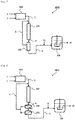
- FIG. 1 illustrates a production system 1000 for ammonia water including a source gas production apparatus 101, an ammonia synthesis apparatus 102, an ammonia concentration apparatus 103 selected from a pressurized cooling apparatus and a PSA apparatus, and an ammonia water production apparatus 201.
- a hydrogen source gas 1 and air 2 are supplied to the source gas production apparatus 101.
- the hydrogen source gas 1 may be a hydrocarbon (coal, petroleum, natural gas, or biomass, for example) or water in accordance with a hydrogen production process in the source gas production apparatus 101.
- Examples of the hydrogen production process include, as described above, 1) a method that transforms a hydrocarbon into gas containing CO and H 2 by a steam reforming reaction, a partial oxidation reaction, or a combination of these reactions and then performs a CO shift reaction and decarbonation processing, 2) a method that electrolyzes water, and 3) a method that decomposes water using a photocatalyst.
- the source gas production apparatus 101 also produces nitrogen. Nitrogen may be prepared by separating nitrogen from air using a nitrogen separation membrane or a cryogenic separation method. Alternatively, when hydrogen is prepared utilizing the partial oxidation reaction of the hydrocarbon, nitrogen within air used as an oxygen source may be used.
- a source gas 3 containing hydrogen and nitrogen produced by the source gas production apparatus 101 is supplied to the ammonia synthesis apparatus 102.
- the ammonia-containing gas is synthesized by reaction of the source gas containing hydrogen and nitrogen in the presence of the supported metal catalyst containing the support of above-specified i) to iii).
- a synthesized ammonia-containing gas 4 is supplied to the ammonia concentration apparatus 103 selected from the pressurized cooling apparatus and the PSA apparatus.
- the ammonia concentration apparatus 103 is the pressurized cooling apparatus, liquid ammonia 6 is obtained.
- the ammonia concentration apparatus 103 is the PSA apparatus, concentrated ammonia gas 6 is obtained.
- the obtained liquid ammonia or concentrated ammonia gas may be stored in a storage tank (not illustrated).
- the obtained liquid ammonia or the concentrated ammonia gas 6 is supplied to the ammonia water production apparatus 201.
- Water 7 is also supplied to the ammonia water production apparatus 201.
- the ammonia water production apparatus dissolves the liquid ammonia or the concentrated ammonia gas 6 in the water 7 and can thereby produce ammonia water 8.
- the method and conditions of dissolution are not limited to particular ones so long as they can produce ammonia water with expected concentration; any of known methods and conditions may be used.
- the production system 1000 illustrated in FIG. 1 includes a recycle apparatus (not illustrated) that recovers unreacted hydrogen and nitrogen separated by the ammonia concentration apparatus 103 and recycles a recovered gas 5 to the upstream side of the ammonia synthesis apparatus 102.
- FIG. 2 illustrates a production system 1001 for ammonia water including the source gas production apparatus 101, the ammonia synthesis apparatus 102, gas separation membrane apparatuses (ammonia concentration apparatuses) 104 and 105, and the ammonia water production apparatus 201.
- the source gas production apparatus 101, the ammonia synthesis apparatus 102, and the ammonia water production apparatus 201 are as described in the production system 1000.
- the production system 1001 includes the gas separation membrane apparatuses 104 and 105 as the ammonia concentration apparatus.
- a hydrogen gas separation membrane 104 and a nitrogen gas separation membrane 105 can be used in combination, for example.
- the production system 1001 including the gas separation membrane apparatuses 104 and 105 can obtain the concentrated ammonia gas 6.
- the obtained concentrated ammonia gas may be stored in a storage tank (not illustrated).
- the production system 1001 illustrated in FIG. 2 includes a recycle apparatus that recovers unreacted hydrogen and nitrogen separated by the gas separation membrane apparatuses 104 and 105 and recycles the recovered gas 5 to the upstream side of the ammonia synthesis apparatus 102.
- FIG. 3 illustrates a production system 1002 for ammonia water including the source gas production apparatus 101, the ammonia synthesis apparatus 102, a cooler 106, and the ammonia water production apparatus 201.
- the source gas production apparatus 101, the ammonia synthesis apparatus 102, and the ammonia water production apparatus 201 are as described in the production system 1000.
- the ammonia-containing gas 4 obtained by using the ammonia synthesis apparatus 102 is cooled by the cooler 106.
- the cooled ammonia-containing gas 6 is supplied to the ammonia water production apparatus 201.
- the cooled ammonia-containing gas 6 contains unreacted hydrogen and nitrogen.
- the production system 1002 includes a recycle apparatus that recovers the unreacted hydrogen and nitrogen in the ammonia water production apparatus 201 and recycles a recovered gas 9 to the upstream side of the ammonia synthesis apparatus 102.
- the recovered gas 9 contains water originating from the water 7 used in the ammonia water production apparatus 201.
- the recycle apparatus includes a dehydrator 107 that removes the water within the recovered gas 9.
- the production system 1002 also includes a drier 108 that further dries the recovered gas 9.
- the production system for ammonia water has been described with reference to FIG. 1 to FIG. 3 ; in the production system, ammonium salts can be produced by using an inorganic acid, an organic acid, or a solution thereof in place of the water 7.
- the production systems illustrated in FIG. 1 to FIG. 3 include the source gas production apparatus 101; a hydrogen supply apparatus such as a hydrogen cylinder or a hydrogen tank and a nitrogen supply apparatus such as a nitrogen cylinder or a nitrogen tank may be included in place of the source gas production apparatus 101.
- the ammonia water obtained by the ammonia water production apparatus 201 may be subjected to concentrating the ammonia water by a concentration apparatus not illustrated. The method of concentration is performed by a known unit such as heating.
- urea is produced using the ammonia originating from the ammonia-containing gas obtained by using the ammonia synthesis apparatus.
- Urea can be produced by performing reaction of ammonia and carbon dioxide in accordance with a formula: 2NH 3 + CO 2 ⁇ CO (NH 2 ) 2 + H 2 O. Also in the production system of the present invention, the urea production apparatus that produces urea from ammonia and carbon dioxide is suitably used. FIG. 4 to FIG. 6 illustrate embodiments using such a urea production apparatus.
- FIG. 4 illustrates a production system 2000 for urea including the source gas production apparatus 101, the ammonia synthesis apparatus 102, the ammonia concentration apparatus 103 selected from the pressurized cooling apparatus and the PSA apparatus, and a urea production apparatus 202.
- the source gas production apparatus 101, the ammonia synthesis apparatus 102, and the ammonia concentration apparatus 103 selected from the pressurized cooling apparatus and the PSA apparatus are as described in the production system 1000.
- the liquid ammonia or the concentrated ammonia gas 6 obtained by the ammonia concentration apparatus 103 may be supplied to the urea production apparatus 202 as it is or supplied to the urea production apparatus 202 after being stored in a storage tank (not illustrated).
- Carbon dioxide 10 is also supplied to the urea production apparatus 201.
- hydrogen is produced by the steam reforming reaction of a hydrocarbon or the like in the source gas production apparatus 101, carbon dioxide in off-gas produced during the reaction may be used.
- the urea production apparatus 202 can produce urea 11 by performing reaction of ammonia and carbon dioxide in accordance with the formula.
- the conditions of the urea production reaction are not limited to particular conditions so long as urea can be produced from ammonia and carbon dioxide in accordance with the formula; the reaction can be generally performed under conditions including 14 MPa to 25 MPa and 170°C to 210°C (Japanese Patent Application Laid-open No. H08-325222 , for example).
- the production system 2000 illustrated in FIG. 4 includes a recycle apparatus that recovers hydrogen and nitrogen separated by the ammonia concentration apparatus 103 and recycles the recovered gas 5 to the upstream side of the ammonia synthesis apparatus 102.
- FIG. 5 illustrates a production system 2001 for urea including the source gas production apparatus 101, the ammonia synthesis apparatus 102, the gas separation membrane apparatuses (the ammonia concentration apparatuses) 104 and 105, and the urea production apparatus 202.
- the source gas production apparatus 101, the ammonia synthesis apparatus 102, the gas separation membrane apparatuses (the ammonia concentration apparatuses) 104 and 105, and the urea production apparatus 202 are as described above.
- the production system 2001 includes a recycle apparatus that recovers unreacted hydrogen and nitrogen separated by the gas separation membrane apparatuses 104 and 105 and recycles the recovered gas 5 to the upstream side of the ammonia synthesis apparatus 102.
- the concentrated ammonia gas obtained by the gas separation membrane apparatuses 104 and 105 may be supplied to the urea production apparatus 202 as it is or supplied to the urea production apparatus 202 after being stored in a storage tank (not illustrated).
- FIG. 6 illustrates a production system 2002 for urea including the source gas production apparatus 101, the ammonia synthesis apparatus 102, the cooler 106, and the urea production apparatus 202.
- the source gas production apparatus 101, the ammonia synthesis apparatus 102, the cooler 106, and the urea production apparatus 202 are as described above.
- the ammonia-containing gas 4 obtained by using the ammonia synthesis apparatus 102 is cooled by the cooler 106.
- the cooled ammonia-containing gas 6 is supplied to the urea production apparatus 202.
- the cooled ammonia-containing gas 6 contains unreacted hydrogen and nitrogen.
- the production system 2002 includes a recycle apparatus that recovers the unreacted hydrogen and nitrogen in the urea production apparatus 202 and recycles a recovered gas 12 to a decarbonation unit (the upstream side of the ammonia synthesis apparatus 102) of the source gas production apparatus 101.
- the recovered gas 12 contains water originating from the urea production reaction.
- the recycle apparatus includes the dehydrator 107 that removes the water within the recovered gas 12.
- the production system 2002 also includes the drier 108 that further dries the recovered gas 12.
- nitric acid can be produced by Ostwald process in the presence of an appropriate catalyst using water in place of the carbon dioxide 10.
- the obtained nitric acid may be further reacted to produce nitrates (potassium nitrate and sodium nitrate, for example).
- the production systems illustrated in FIG. 4 to FIG. 6 include the source gas production apparatus 101; a hydrogen supply apparatus such as a hydrogen cylinder or a hydrogen tank and a nitrogen supply apparatus such as a nitrogen cylinder or a nitrogen tank may be included in place of the source gas production apparatus 101.
- a fermented and cultured product is produced using the ammonia originating from the ammonia-containing gas obtained by using the ammonia synthesis apparatus.
- Examples of the fermented and cultured product include organic compounds such as amino acids, organic acids, polysaccharides, proteins, antibiotics, and alcohols and microbial cells.
- Examples of the amino acids include glycine, alanine, valine, leucine, isoleucine, serine, threonine, cysteine, cystine, methionine, phenylalanine, tyrosine, tryptophan, proline, hydroxyproline, asparagine, glutamine, aspartic acid, glutamic acid, lysine, histidine, and arginine.
- Examples of the organic acids include acetic acid, lactic acid, pyruvic acid, succinic acid, malic acid, itaconic acid, citric acid, acrylic acid, propionic acid, and fumaric acid.
- Examples of the polysaccharides include xanthan, dextran, alginate, hyaluronic acid, curdlan, gellan, scleroglucan, and pullulan.
- Examples of the proteins include hormones, lymphokines, interferons, and enzymes (such as amylase, glucoamylase, invertase, lactase, protease, and lipase).
- antibiotics examples include antimicrobial agents (such as ⁇ -lactams, macrolides, ansamycin, tetracycline, chloramphenicol, peptidergic antibiotics, and aminoglycosides), antifungal agents (such as polyoxin B, griseofulvin, and polyenemacrolides), anticancer agents (daunomycin, adriamycin, dactinomycin, mithramycin, and bleomycin), protease/peptidase inhibitors (such as leupeptin, antipain, and pepstatin), and cholesterol biosynthesis inhibitors (such as compactin, lovastatin, and pravastatin).
- antimicrobial agents such as ⁇ -lactams, macrolides, ansamycin, tetracycline, chloramphenicol, peptidergic antibiotics, and aminoglycosides
- antifungal agents such as polyoxin B, griseofulvin, and polyenemacrolides
- the alcohols include ethanol, isopropanol, glycerin, propylene glycol, trimethylene glycol, 1-butanol, and sorbitol.
- Other examples of the fermented and cultured product include organic compounds such as acrylamide, diene compounds (such as isoprene), and pentanediamine. Techniques that culture microorganisms having organic compound productivity to produce the above organic compounds are widely known. The present invention can be applied widely to such microorganism fermentation techniques. In microorganism fermentation, microorganisms themselves grow utilizing a carbon source, a nitrogen source, or the like. In that sense, in the present invention, the fermented and cultured product includes microbial cells. Examples of the microbial cells include any microorganisms having organic compound productivity.
- the microorganisms having organic compound productivity include both 1) microorganisms intrinsically having organic compound productivity and 2) microorganisms that have acquired organic compound productivity through the introduction of organic compound production genes by gene recombination although they do not have or do not substantially have organic compound productivity intrinsically.
- various kinds of microorganisms are known in accordance with the type of organic compounds; in the present invention, these known microorganisms may be widely used. So long as ammonia can be used as the nitrogen source or the pH adjuster in culture, the present invention can be widely applied also to microorganisms to be developed in the future.
- the microorganisms which are not limited to particular microorganisms so long as they have organic compound productivity, are preferably bacteria or fungi.
- the bacteria include the Escherichia bacteria, the Pantoea bacteria, the Corynebacterium bacteria, the Enterobacter bacteria, the Clostridium bacteria, the Bacillus bacteria, the Lactobacillus bacteria, the Streptomyces bacteria, the Streptococcus bacteria, and the Pseudomonas bacteria.
- fungi examples include the Saccharomyces fungi, the Schizosaccharomyces fungi, the Yarrowia fungi, the Trichoderma fungi, the Aspergillus fungi, the Fusarium fungi, and the Mucor fungi.
- Examples of the Escherichia bacteria include Escherichia coli.
- Examples of the Pantoea bacteria include Pantoea ananatis.
- Examples of the Corynebacterium bacteria include Corynebacterium glutamicum and Corynebacterium ammoniagenes.
- Examples of the Enterobacter bacteria include Enterobacter aerogenes.
- Examples of the Clostridium bacteria include Clostridium acetobutylicum.
- Examples of the Bacillus bacteria include Bacillus subtilis and Bacillus amyloliquefaciens.
- Examples of the Lactobacillus bacteria include Lactobacillus yamanashiensis, Lactobacillus animalis, Lactobacillus hilgardii, and Lactobacillus brevis.
- Streptomyces bacteria examples include Streptomyces clavuligerus, Streptomyces venezuelae, and Streptomyces peucetius.
- Streptococcus bacteria examples include Streptococcus equi and Streptococcus mutans.
- Pseudomonas bacteria examples include Pseudomonas fluorescens, Pseudomonas aeruginosa, Pseudomonas elodea, and Pseudomonas putida.
- Saccharomyces fungi examples include Saccharomyces cerevisiae.
- Examples of the Schizosaccharomyces fungi include Schizosaccharomyces pombe.
- Examples of the Yarrowia fungi include Yarrowia lipolytica.
- Examples of the Trichoderma fungi include Trichoderma reesei.
- Examples of the Aspergillus fungi include Aspergullus terreus and Aspergillus oryzae.
- Examples of the Fusarium fungi include Fusarium hetereosporum.
- Examples of the Mucor fungi include Mucor javanicus.
- examples of the microorganisms that can be suitably used include the following: when the target substance is L-lysine, for example, examples thereof include Escherichia Coli A J11442 (NRRL B-12185, FERM BP-1543) (refer to United States Patent No. 4,346,170 ), Brevibacterium lactofermentum AJ3990 (ATCC31269) (refer to United States Patent No. 4,066,501 ), and Lys-producing bacteria WC196LC/pCABD2 ( WO 2010/061890 ).
- WC196 ⁇ cadA ⁇ ldc is a strain constructed by destroying the cadA and ldcC genes that code lysine decarboxylase from the WC196 strain.
- WC196AcadA ⁇ ldc/pCABD2 is a strain constructed by introducing a plasmid pCABD2 (United States Patent No. 6,040,160 ) containing a lysine biosynthetic gene to WC196 ⁇ cadA ⁇ ldc.
- WC196 ⁇ cadA ⁇ ldc was named AJ110692 and was deposited at International Patent Organism Depositary, National Institute of Advanced Industrial Science and Technology (currently Patent Microorganisms Depositary, National Institute of Technology and Evaluation, No.
- L-threonine examples include Escherichia Coli VKPM B-3996 (RIA 1867, VKPM B-3996) (refer to United States Patent No. 5,175,107 ) and Corynebacterium acetoacidophilum AJ12318 (FERM BP-1172) (refer to United States Patent No. 5,188,949 ); examples thereof for L-phenylalanine include Escherichia Coli AJ12604 (FERM BP-3579) (refer to European Patent Application Laid-open No.
- L-leucine examples thereof include Escherichia Coli AJ11478 (FERM P-5274) (refer to Japanese Examined Patent Application Publication No. S62-34397 ) and Brevibacterium lactofermentum AJ3718 (FERM P-2516) (refer to United States Patent No. 3,970,519 ); examples thereof for L-isoleucine include Escherichia Coli KX141 (VKPM B-4781) (refer to European Patent Application Laid-open No.
- L-valine examples include Escherichia Coli VL1970 (VKPM B-4411) (refer to European Patent Application Laid-open No. 519,113 ) and Brevibacterium lactofermentum AJ12341 (FERM BP-1763) (refer to United States Patent No. 5,188,948 ).
- examples of the microorganisms that can be suitably used include the following: when the target substance is L-lactic acid, for example, examples thereof include Lactobacillus yamanashiensis, Lactobacillus animalis, and Saccharomyces cerevisiae; examples thereof for pyruvic acid include Escherichia Coli and Pseudomonas fluorescens; examples thereof for succinic acid include Escherichia Coli and Pantoea ananatis; examples thereof for itaconic acid include Aspergillus terreus; and examples thereof for citric acid include Escherichia Coli (refer to WO 2007/097260 and Japanese Patent Application Laid-open No. 2010-187542 , for example).
- examples of the microorganisms that can be suitably used include the following: when the target substance is dextran, for example, examples thereof include Lactobacillus hilgardii and Streptococcus mutans; examples thereof for alginate include Pseudomonas aeruginosa; examples thereof for hyaluronic acid include Streptococcus equi and Streptococcus mutans; and examples thereof for gellan include Pseudomonas elodea (refer to Japanese Patent Application Laid-open No. 2011-116825 and Japanese Patent Application Laid-open No. 2007-9092 , for example).
- examples of the microorganisms that can be suitably used include the following: when the target substance is any of various kinds of hormones or interferons, for example, examples thereof include Saccharomyces cerevisiae; examples thereof for amylase, glucoamylase, protease, or lipase include Bacillus subtilis and Aspergillus oryzae; and examples thereof for invertase or lactase include Saccharomyces cerevisiae and Aspergillus oryzae (refer to WO 2006/67511 and Japanese Patent Application Laid-open No. 2003-153696 , for example).
- examples of the microorganisms that can be suitably used include the following: when the target substance is a ⁇ -lactam such as penicillin, for example, examples thereof include Pseudomonas putida and Streptomyces clavuligerus; examples thereof for macrolides such as erythromycin and azithromycin include Streptomyces venezuelae; examples thereof for daunomycin include Streptomyces peucetius; examples thereof for pravastatin include Streptomyces clavuligerus (refer to WO 96/10084 , Japanese Patent Application Laid-open No. 2002-53589 , WO 2005/54265 , and WO 2007/147827 , for example).
- examples thereof include Pseudomonas putida and Streptomyces clavuligerus
- examples thereof for macrolides such as erythromycin and azithromycin include Streptomyces venezuelae
- examples thereof for daunomycin include Streptomy
- examples of the microorganisms that can be suitably used include the following: when the target substance is ethanol, for example, examples thereof include Saccharomyces cerevisiae, Schizosaccharomyces pombe, and Lactobacillus brevis; and examples thereof for trimethylene glycol include Escherichia coli (refer to WO 2007/97260 , for example).
- the fermented and cultured product production apparatus is not limited to a particular apparatus so long as it can produce the fermented and cultured product using ammonia as the nitrogen source or the pH adjuster; any known apparatuses may be used depending on the type of the fermented and cultured product.
- FIG. 7 to FIG. 10 illustrate embodiments using a fermentation and culture tank.
- FIG. 7 illustrates a production system 3000 for a fermented and cultured product including the source gas production apparatus 101, the ammonia synthesis apparatus 102, the ammonia concentration apparatus 103 selected from the pressurized cooling apparatus and the PSA apparatus, and a fermented and cultured product production apparatus 203.
- the source gas production apparatus 101, the ammonia synthesis apparatus 102, and the ammonia concentration apparatus 103 selected from the pressurized cooling apparatus and the PSA apparatus are as described in the production system 1000.
- the liquid ammonia or the concentrated ammonia gas 6 obtained by the ammonia concentration apparatus 103 may be directly supplied to the fermented and cultured product production apparatus 203 or supplied to the fermented and cultured product production apparatus 203 after being stored in a storage tank (not illustrated).
- An appropriate fermentation and culture medium liquid in accordance with the type of the fermentation and culture product to be produced is introduced to the fermented and cultured product production apparatus 203, and air 13 is supplied thereto as needed to perform fermentation and culture using the ammonia 6 as the nitrogen source or the pH adjuster, whereby a fermented and cultured product 14 can be produced.
- Fermentation and culture conditions are not limited to particular conditions so long as the conditions can produce the fermented and cultured product to be produced; any of standard fermentation and culture conditions may be used.
- the fermentation and culture temperature is normally preferably 20°C to 37°C.
- fermentation and culture may be performed under an aerobic, anoxic, or anaerobic condition.
- known methods such as a batch method, a fed-batch method, and a continuous method may be used.
- the production system 3000 illustrated in FIG. 7 includes a recycle apparatus that recovers unreacted hydrogen and nitrogen separated by the ammonia concentration apparatus 103 and recycles the recovered gas 5 to the upstream side of the ammonia synthesis apparatus 102.
- FIG. 8 illustrates a production system 3001 for a fermented and cultured product including the source gas production apparatus 101, the ammonia synthesis apparatus 102, the gas separation membrane apparatuses (the ammonia concentration apparatuses) 104 and 105, and the fermented and cultured product production apparatus 203.
- the source gas production apparatus 101, the ammonia synthesis apparatus 102, the gas separation membrane apparatuses (the ammonia concentration apparatuses) 104 and 105, and the fermented and cultured product production apparatus 203 are as described above.
- the production system 3001 includes a recycle apparatus that recovers unreacted hydrogen and nitrogen separated by the gas separation membrane apparatuses 104 and 105 and recycles the recovered gas 5 to the upstream side of the ammonia synthesis apparatus 102.
- the concentrated ammonia gas obtained by the gas separation membrane apparatuses 104 and 105 may be supplied to the fermented and cultured product production apparatus 203 as it is or supplied to the fermented and cultured product production apparatus 203 after being stored in a storage tank (not illustrated).
- FIG. 9 illustrates a production system 3002 for a fermented and cultured product including the source gas production apparatus 101, the ammonia synthesis apparatus 102, the cooler 106, and the fermented and cultured product production apparatus 203.
- the source gas production apparatus 101, the ammonia synthesis apparatus 102, and the cooler 106 are as described above.
- the fermented and cultured product production apparatus 203 includes a premixer 204. Between the premixer 204 and the fermentation and culture tank of the fermented and cultured product production apparatus 203, the fermentation and culture medium liquid circulates. In the premixer 204, ammonia is premixed with the circulating fermentation and culture medium liquid. With this premixing, the fermentation and culture medium liquid mixed with ammonia is supplied to the fermentation and culture tank of the fermented and cultured product production apparatus 203.
- the ammonia-containing gas 4 obtained by using the ammonia synthesis apparatus 102 is cooled by the cooler 106.
- the cooled ammonia-containing gas 6 is supplied to the premixer 204.
- the cooled ammonia-containing gas 6 contains unreacted hydrogen and nitrogen.
- the production system 3002 includes a recycle apparatus that recovers the unreacted hydrogen and nitrogen in the premixer 204 and recycles a recovered gas 15 to the upstream side of the ammonia synthesis apparatus 102.
- the recovered gas 15 contains water originating from the fermentation and culture medium liquid.
- the recycle apparatus includes the dehydrator 107 that removes the water within the recovered gas 15.
- the production system 3002 also includes the drier 108 that further dries the recovered gas 15.
- FIG. 10 illustrates a production system 3003 for a fermented and cultured product including the source gas production apparatus 101, the ammonia synthesis apparatus 102, the cooler 106, the ammonia water production apparatus 201, an ammonia stripping apparatus 205, and the fermented and cultured product production apparatus 203.
- the source gas production apparatus 101, the ammonia synthesis apparatus 102, the cooler 106, and the ammonia water production apparatus 201 are as described above.
- the production system 3003 is a modification of the production system 1002.
- the produced ammonia water 8 is used further for the production of the fermented and cultured product.
- the produced ammonia water 8 is supplied to the ammonia stripping apparatus 205 to recover ammonia gas from the ammonia water.
- the ammonia stripping apparatus 205 is not limited to a particular apparatus so long as it can recover the ammonia gas from the ammonia water; any of known stripping apparatuses may be used.
- the ammonia gas recovered by the ammonia stripping apparatus 205 is supplied as the nitrogen source or the pH adjuster to the fermented and cultured product production apparatus 203 to perform fermentation and culture, whereby the fermented and cultured product 14 can be produced. Water 12 removed by the ammonia stripping apparatus 205 may be merged with the water 7 as illustrated in FIG. 10 or discharged.
- the production system 3003 can also transport the ammonia water 8 produced by the ammonia water production apparatus 201 and produce the fermented and cultured product at geographically remote sites.
- the production system 3003 is a production system for a fermented and cultured product
- the fermented and cultured product production apparatus 203 may be replaced with a production apparatus for other nitrogen-containing products such as urea, nitric acid, and nitrates. Such a modification is also included in the production system of the present invention.
- the production systems for a fermented and cultured product have been described with reference to FIG. 7 to FIG. 10 ; in the production systems, a hydrogen supply apparatus such as a hydrogen cylinder or a hydrogen tank and a nitrogen supply apparatus such as a nitrogen cylinder or a nitrogen tank may be used in place of the source gas production apparatus 101.
- a hydrogen supply apparatus such as a hydrogen cylinder or a hydrogen tank
- a nitrogen supply apparatus such as a nitrogen cylinder or a nitrogen tank
- the concentrated ammonia 6 such as the liquid ammonia or the concentrated ammonia gas is also suitably supplied to the fermented and cultured product production apparatus 203 after being converted into ammonia water.
- the nitrogen-containing product produced by the production system of the present invention is suitably used as raw materials of various kinds of chemical products and fertilizers.
- the fermented and cultured product produced by the production system of the present invention is suitably used for foods, drugs, chemical reagents, and the like.
- the present invention also provides a novel method of production for the ammonia-related products.
- the method of production of the present invention does not involve (or minimizes) the transport of liquid ammonia.
- the method of production of the present invention is a method of production for a product selected from a nitrogen-containing product and a fermented and cultured product, the method including:
- the supported metal catalyst, the source gas, the ammonia-containing gas used in Process (A) and conditions (temperature, pressure, and the like) when the ammonia-containing gas is synthesized are as described in [Production System].
- the nitrogen-containing product and the fermented and cultured product produced in Process (B) and the method of production for the same are as described in [Production System].
- the advantageous effects described for the production system of the present invention are also applied to the method of production of the present invention similarly.
- Process (A) and Process (B) are successively performed.
- Process (A) and Process (B) are successively performed means that the ammonia-containing gas synthesized in Process (A) is subjected to Process (B) without being transported as liquid ammonia.
- Process (B) without being transported as liquid ammonia.
- Being transported as liquid ammonia means transport between two geographically remote sites by pipeline, air, ship, automobile, and the like and does not include transport within a production site of the ammonia-related products.
- the method of production of the present invention may further include a process of producing the source gas containing hydrogen and nitrogen from the hydrogen source gas and air.
- the methods of production for the hydrogen source gas and the source gas are as described in [Production System].
- the method of production of the present invention may further include a process of concentrating the ammonia within the ammonia-containing gas obtained in Process (A).
- the method for concentrating the ammonia within the ammonia-containing gas is as described in [Production System] .
- the method of production of the present invention may further include a process (hereinafter, referred to as Process (C)) of recovering unreacted hydrogen and nitrogen and recycling a recovered gas to Process (A).
- Process (C) may include dehydration treatment and/or drying treatment removing water within the recovered gas. The methods of dehydration treatment and the drying treatment are as described in [Production System].
- One preferred embodiment of the method of production of the present invention produces ammonia water using the ammonia originating from the ammonia-containing gas obtained in Process (A) and produces a fermented and cultured product using the obtained ammonia water in Process (B).
- Another preferred embodiment of the method of production of the present invention produces ammonia water using the ammonia originating from the ammonia-containing gas obtained in Process (A), recovers ammonia gas from the obtained ammonia water, and produces a fermented and cultured product using the recovered ammonia gas in Process (B) .
- the method of production of the present invention may further include collecting a metabolite from a medium liquid after the end of fermentation and culture.
- the method for collecting the metabolite is not limited to a particular method; the metabolite can be collected by combining an ion exchange resin method, a precipitation method, and other methods that have been conventionally commonly known.
- a reaction in which nitrogen gas (N 2 ) and hydrogen gas (H 2 ) react to produce ammonia gas (NH 3 ) was performed.
- the obtained catalyst in an amount of 0.2 g was charged into a glass tube, and the reaction was performed by a fixed bed flow reactor.
- the gas flows were set to N 2 : 15 mL/min and H 2 : 45 mL/min giving a total of 60 mL/min, and the reaction was performed at a pressure of atmospheric pressure and a reaction temperature of 400°C.
- the gas that had emerged from the flow reactor was bubbled in a 0.005 M aqueous sulfuric acid solution to dissolve the produced ammonia in the solution, and the produced ammonium ions were quantified by an ion chromatograph.
- the production rate of ammonia at 400°C was 2, 760 ⁇ molg -1 h -1 .
- ZrO 2 (SZ31164, Saint-Gobain NorPro) with a specific surface area of 100 m 2 /g was evacuated at 500°C for 5 hours and was then put into a stainless pressure-resistant container within a glove box in an Ar atmosphere, and metal Ca was put thereinto so as to be 40 wt% as Ca(NH 2 ) 2 .
- the sealed pressure-resistant container was taken out of the glove box, and ammonia gas was introduced thereto, while being cooled to about -50°C.
- the pressure-resistant container was agitated for a while, was heated at 100°C for 2 hours, and was cooled to room temperature to remove the ammonia gas.
- the obtained powder (Ca(NH 2 ) 2 / ZrO 2 ) was collected within the glove box in an Ar atmosphere.
- the powder (Ca(NH 2 ) 2 /ZrO 2 ) was physically mixed with Ru 3 (CO) 12 so as to give a Ru support amount of 5 wt% relative to Ca(NH 2 ) 2 /ZrO 2 and was encapsulated in vacuum quartz glass.
- the encapsulated sample was heated at 250°C for 15 hours. With this procedure, a Ca(NH 2 ) 2 /ZrO 2 catalyst supporting Ru metal was obtained.
- the BET surface area of this catalyst was 64 m 2 /g.
- a reaction in which nitrogen gas (N 2 ) and hydrogen gas (H 2 ) react to produce ammonia gas (NH 3 ) was performed.
- the obtained catalyst in an amount of 0.2 g was charged into a glass tube, and the reaction was performed by a fixed bed flow reactor.
- the gas flows were set to N 2 : 15 mL/min and H 2 : 45 mL/min giving a total of 60 mL/min, and the reaction was performed at a pressure of atmospheric pressure and a reaction temperature of 340°C.
- the gas that had emerged from the flow reactor was bubbled in a 0.005 M aqueous sulfuric acid solution to dissolve the produced ammonia in the solution, and the produced ammonium ions were quantified by an ion chromatograph.
- the production rate of ammonia at 340°C was 7, 387 ⁇ molg -1 h -1 .
- ZrO 2 powder manufactured by Saint-Gobain NorPro, Product No.: SZ 31164
- the dehydrated ZrO 2 powder was put into a 30 cc stainless steel pressure-resistant container within a glove box in an Ar atmosphere, and 0.25 g of metal Ca powder (purity: 99.99%, manufactured by Aldrich, Product No.: 215147) was put thereinto so as to give 40 wt% of Ca(NH 2 ) 2 to be produced relative to a total amount together with ZrO 2 .
- the sealed pressure-resistant container was taken out of the glove box.
- the pressure-resistant container was immersed in ethanol, and ammonia gas was introduced thereto, while being cooled to about -50°C. Liquid ammonia was charged into the pressure-resistant container, and the pressure-resistant container was agitated at 1,000 rpm for 1 hour.
- the pressure-resistant container was immersed in an oil bath to perform a heating reaction at 100°C and was agitated at 500 rpm for 2 hours. After the pressure-resistant container was cooled to room temperature, the residual ammonia gas was removed from the pressure-resistant container. Ca(NH 2 ) 2 /ZrO 2 within the pressure-resistant container was collected within a glove box in an Ar atmosphere.
- Ca(NH 2 ) 2 /ZrO 2 powder in an amount of 0.30 g and Ru 3 (CO) 12 powder (99%, manufactured by Aldrich, Product No.: 245011) in an amount of 0.035 g were mixed using an agate mortar so as to give a Ru support amount of 5 wt% relative to a Ru/Ca(NH 2 ) 2 /ZrO 2 catalyst, and the mixture was encapsulated in a vacuum Pyrex (registered trademark) tube. The sample put into the Pyrex tube was heated at 250°C for 15 hours. With this procedure, 0.29 g of a catalyst in which the Ca(NH 2 ) 2 /ZrO 2 powder supports Ru metal was obtained.
- a reaction in which nitrogen gas (N 2 ) and hydrogen gas (H 2 ) react to produce ammonia gas (NH 3 ) was performed.
- the obtained catalyst in an amount of 0.2 g was charged into a pressure-resistant tube, and the reaction was performed by a fixed bed flow reactor.
- the gas flows were set to N 2 : 15 mL/min and H 2 : 45 mL/min giving a total of 60 mL/min, and the reaction was performed at a pressure of 0.9 MPa and a reaction temperature of 340°C.
- the gas that had emerged from the fixed bed flow reactor was passed through water cooled at about 3°C to dissolve the produced NH 3 in the water, and the produced ammonium ions (NH 4 + ) were quantified by an ion chromatograph.
- Aqueous Ammonia 1 liquid amount: 200 g, NH 4 + amount: 1.78 g was obtained in about 43 hours.
- NH 3 produced by a method similar to that of Reference Example 3 was dissolved in water to obtain an aqueous ammonia (liquid amount: 200 g, NH 4 + amount: 3.02 g) in about 92 hours.
- Concentration was performed using the obtained aqueous ammonia.
- the obtained aqueous ammonia 200 g was put into a concentration side flask and was heated at 90°C.
- NH 3 gas that had volatilized was passed through 100 g of cooled receiver tank water to dissolve NH 3 , and NH 4 + in the receiver tank water was quantified by an ion chromatograph.
- Ar gas 50 mL/min was passed through the concentration side flask to promote the volatilization of NH 3 gas. Based on this condition, Aqueous Ammonia 2 (liquid amount: 100 g, NH 4 + amount: 1.89 g) was obtained in about 5 hours.
- the concentration rate was 1.29 (NH 4 + concentration after concentration: 18.9 g/L, NH 4 + concentration before concentration: 14.7 g/L).
- CaCO 3 (purity: 99.99%, manufactured by Kojundo Chemical Laboratory Co., Ltd., Product No.: CAH23PB) and Al 2 O 3 (purity: 99.99%, manufactured by Kanto Chemical Co., Inc., Product No.: 01173), both in powder form, were mixed so as to give the molar ratio between Ca and Al of 11:7 and were heated in an alumina crucible at 1,300°C for 6 hours. The obtained powder was inserted into a silica glass tube and was heated at 1,100°C for 15 hours in a vacuum of 1 ⁇ 10 -4 Pa.
- the obtained powder in an amount of 3 g was inserted into a silica glass tube together with 0.18 g of metal Ca powder and was heated at 700°C for 15 hours to make a metal Ca vapor atmosphere therewithin, and a 12CaO ⁇ 7Al 2 O 3 electride (denoted by C12A7e 21 ) in powder form was obtained.
- the C12A7e 21 powder in an amount of 1.00 g was dissolved in a hexane solvent, 0.04 g of Ru 3 (CO) 12 was mixed therewith so as to give a Ru support amount of 2 wt% relative to a Ru/C12A7e 12 catalyst, and the solvent was evaporated to be dried and solidified.
- the obtained powder was heated in a vacuum at 100°C for 4 hours to remove the residual solvent component, and a catalysis precursor was formed.
- the precursor was then subjected to heating treatment at 400°C for 3 hours in a hydrogen gas (26.7 kPa) atmosphere to reduce Ru 3 (CO) 12 .
- a catalyst in which the C12A7e 21 powder supports Ru metal was obtained in an amount of 1.02 g.
- the catalyst was changed from Ca(NH 2 ) 2 /ZrO 2 supporting Ru to C12A7e 21 supporting Ru, the catalyst amount was changed from 0.2 g to 0.5 g, the pressure was changed to 0.5 MPa, and the reaction temperature was changed from 340°C to 400°C.
- the ammonia water was produced similarly to Reference Example 3 except the above matters.
- the production rate of ammonia at 400°C was 2,191 ⁇ molg -1 h -1 .
- Aqueous Ammonia 4 (liquid amount: 200 g, NH 4 + amount: 2.04 g) was obtained in about 106 hours.
- Ca 3 N 2 powder in an amount of 1.00 g (purity: 95%, manufactured by Aldrich, Product No.: 415103) was mixed with 0.04 g of Ru 3 (CO) 12 powder using an agate mortar within a glove box in an Ar atmosphere so as to give a Ru support amount of 2 wt% relative to a Ru/Ca 3 N 2 catalyst, and the mixture was encapsulated in a vacuum Pyrex tube.
- the sample put into the Pyrex tube was heated at 250°C for 15 hours to obtain 1.02 g of a catalyst in which the Ca 3 N 2 powder supports Ru metal.
- the obtained catalyst in an amount of 0.5 g was charged into a mold and was compressed to 10 MPa by a hydraulic pump, and a molded product was obtained using a molding apparatus (manufactured by JASCO Corporation, PT-10).
- the obtained molded product was roughly crushed with an agate mortar and was used as a molded catalyst (molded product) for the production of ammonia water.
- the ammonia gas synthesized in Reference Example 1 was dissolved in water to obtain ammonia water.
- Ammonia gas was recovered from the obtained ammonia water using an ammonia stripping apparatus, and using the ammonia gas, E. coli MG1655 was cultured.
- the ammonia gas obtained in the present invention was revealed to be able to be used for fermentation and culture production.
- the ammonia gas synthesized in Reference Example 2 was dissolved in water to obtain ammonia water.
- Ammonia gas was recovered from the obtained ammonia water using an ammonia stripping apparatus, and using the ammonia gas, E. coli MG1655 was cultured.
- the ammonia gas obtained in the present invention was revealed to be able to be used for fermentation and culture production.
- Lys-producing bacteria WC196 ⁇ cadA ⁇ ldc/pCABD2 were cultured in the LB agar medium with streptomycin added so as to have a final concentration of 80 mg/L at 37°C for an entire day and night. All the bacteria on the plate with a diameter of 90 mm were scraped together from the LB agar medium after culture and were suspended in a 3 mL of a physiological saline solution to prepare a bacteria solution.
- the bacteria solution was planted to a thick test tube charged with 5 mL of the Lys ammoniacal liquor medium to which streptomycin had been added so as to have a final concentration of 80 mg/L and calcium carbonate dry-sterilized in advance had been added so as to have a final concentration of 30 g/L so as to have an absorbance at a wavelength of 620 nm (O.D. 620 nm) of 0.126, and shake culture was performed at 37°C and 120 rpm for 24 hours.
- 620 nm O.D. 620 nm
- Example 3 Aqueous Ammonia 1 in the Lys ammoniacal liquor medium was changed to Aqueous Ammonia 2 produced in Reference Example 4.
- the production culture of L-lysine was performed similarly to Example 3 except the above matter.
- Example 3 Aqueous Ammonia 1 in the Lys ammoniacal liquor medium was changed to Aqueous Ammonia 3 produced in Reference Example 5.
- the production culture of L-lysine was performed similarly to Example 3 except the above matter.
- Example 3 the Lys ammoniacal liquor medium was changed to the following Lys ammonium sulfate medium.
- the production culture of L-lysine was performed similarly to Example 3 except the above matter.
- Example 3 Aqueous Ammonia 1 in the Lys ammoniacal liquor medium was changed to Aqueous Ammonia 4 produced in Reference Example 7.
- the production culture of L-lysine was performed similarly to Example 3 except the above matter.
- Example 3 Aqueous Ammonia 1 in the Lys ammoniacal liquor medium was changed to Aqueous Ammonia 5 produced in Reference Example 8.
- the production culture of L-lysine was performed similarly to Example 3 except the above matter.
- Example 3 Aqueous Ammonia 1 in the Lys ammoniacal liquor medium was changed to a commercially available aqueous ammonia (manufactured by Junsei Chemical Co., Ltd., Product No.: 13370-0301). The production culture of L-lysine was performed similarly to Example 3 except the above matter.
- Example 6 Ammonium Sulfate Solution 1 in the Lys ammonium sulfate medium was changed to a commercially available ammonium sulfate solution (manufactured by Junsei Chemical Co., Ltd., Product No.: 83110-0367). The production culture of L-lysine was performed similarly to Example 6 except the above matter.
- Glu producing bacteria 2256 ⁇ ldhA ⁇ sucAyggB* of Corynebacterium glutamicum were cultured in the CM-Ace agar medium at 31.5°C for an entire day and night.
- the bacteria corresponding to 1/24 plate were scraped from the agar medium after culture and were planted to a thick test tube charged with 5 mL of the Glu ammoniacal liquor medium to which calcium carbonate dry-sterilized in advance had been added so as to have a final concentration of 30 g/L, and shake culture was performed at 31.5°C and 120 rpm for 24 hours.
- Example 9 Aqueous Ammonia 1 in the Glu ammoniacal liquor medium was changed to Aqueous Ammonia 2 produced in Reference Example 4. The production culture of L-glutamic acid was performed similarly to Example 9 except the above matter.
- Example 9 Aqueous Ammonia 1 in the Glu ammoniacal liquor medium was changed to Aqueous Ammonia 3 produced in Reference Example 5. The production culture of L-glutamic acid was performed similarly to Example 9 except the above matter.
- Example 9 the Glu ammoniacal liquor medium was changed to the following Glu ammonium sulfate medium.
- the production culture of L-glutamic acid was performed similarly to Example 9 except the above matter.
- Example 9 Aqueous Ammonia 1 in the Glu ammoniacal liquor medium was changed to Aqueous Ammonia 4 produced in Reference Example 7. The production culture of L-glutamic acid was performed similarly to Example 9 except the above matter.
- Example 9 Aqueous Ammonia 1 in the Glu ammoniacal liquor medium was changed to Aqueous Ammonia 5 produced in Reference Example 8. The production culture of L-glutamic acid was performed similarly to Example 9 except the above matter.
- Example 9 Aqueous Ammonia 1 in the Glu ammoniacal liquor medium was changed to a commercially available aqueous ammonia (manufactured by Junsei Chemical Co., Ltd., Product No.: 13370-0301). The production culture of L-glutamic acid was performed similarly to Example 9 except the above matter.
- Example 12 Ammonium Sulfate Solution 1 in the Glu ammonium sulfate medium was changed to a commercially available ammonium sulfate solution (manufactured by Junsei Chemical Co., Ltd., Product No.: 83110-0367). The production culture of L-glutamic acid was performed similarly to Example 12 except the above matter.
Landscapes
- Chemical & Material Sciences (AREA)
- Organic Chemistry (AREA)
- Engineering & Computer Science (AREA)
- Life Sciences & Earth Sciences (AREA)
- Zoology (AREA)
- Wood Science & Technology (AREA)
- Chemical Kinetics & Catalysis (AREA)
- Health & Medical Sciences (AREA)
- Bioinformatics & Cheminformatics (AREA)
- Biotechnology (AREA)
- Genetics & Genomics (AREA)
- Microbiology (AREA)
- General Engineering & Computer Science (AREA)
- General Health & Medical Sciences (AREA)
- Biochemistry (AREA)
- General Chemical & Material Sciences (AREA)
- Materials Engineering (AREA)
- Inorganic Chemistry (AREA)
- Analytical Chemistry (AREA)
- Biomedical Technology (AREA)
- Sustainable Development (AREA)
- Medicinal Chemistry (AREA)
- Molecular Biology (AREA)
- Thermal Sciences (AREA)
- Physics & Mathematics (AREA)
- Virology (AREA)
- Mycology (AREA)
- Tropical Medicine & Parasitology (AREA)
- Oil, Petroleum & Natural Gas (AREA)
- Catalysts (AREA)
- Preparation Of Compounds By Using Micro-Organisms (AREA)
- Micro-Organisms Or Cultivation Processes Thereof (AREA)
- Apparatus Associated With Microorganisms And Enzymes (AREA)
Abstract
an ammonia synthesis apparatus in which an ammonia-containing gas is synthesized by reaction of a source gas containing hydrogen and nitrogen in the presence of a supported metal catalyst containing as a support one or more selected from the group consisting of: i) a conductive mayenite compound; ii) a two-dimensional electride compound or a precursor thereof; and iii) a complex formed of a support base containing at least one metal oxide selected from ZrO2, TiO2, CeO2, and MgO and a metal amide represented by a formula M(NH2)x (where M represents one or more selected from Li, Na, K, Be, Mg, Ca, Sr, Ba, and Eu; and x represents a valence number of M) supported by the support base; and
a production apparatus that produces a product selected from a nitrogen-containing product and a fermented and cultured product using ammonia originating from the ammonia-containing gas obtained by using the ammonia synthesis apparatus.
Description
- The present invention relates to a production system and a method of production for a product selected from a nitrogen-containing product and a fermented and cultured product.
- Ammonia has a wide variety of uses such as raw materials of various kinds of nitrogen-containing products, a nitrogen source in fermentation and culture and a pH adjuster.
- As an industrial production process for ammonia, a large-scale production process by the Haber-Bosch process is known. In the Haber-Bosch process, a source gas containing hydrogen and nitrogen reacts under a high-temperature, high-pressure condition at 400°C to 600°C and 20 MPa to 100 MPa using a doubly promoted iron catalyst obtained by adding a few percent by weight of Al2O3 and K2O to Fe3O4 to synthesize ammonia.
- Apart from the doubly promoted iron catalyst used for the Haber-Bosch process, known as ammonia synthesis catalysts are catalysts with ruthenium, cobalt, osmium, rhenium, nickel, or the like as active metals. It is known that a ruthenium catalyst among them exhibits excellent catalytic performance in ammonia synthesis in a low pressure condition.
Patent Literature 1 andNon Patent Literature - Global demand for ammonia is increasing, and ammonia synthesis plants tend to upsize (Non Patent Literature 3, for example).
-
- Non Patent Literature 1: "Ammonia synthesis by 12CaO·7Al2O3 electride supporting ruthenium", Shokubai, Vol. 55, No. 4, 239-245 (2013)
- Non Patent Literature 2: "Ammonia synthesis using a stable electride as an electron donor and reversible hydrogen store", Nature Chemistry, 2012, Vol. 4, 934-940 (2012)
- Non Patent Literature 3: "Saishin Kogyo Shokubai Doko Dai 3-Kai Ammonia Gosei Shokubai", Kogyo Zairyo, Vol. 60, No. 10, 82-86 (2012)
- The synthesis of ammonia by a large-scale production process assumes that obtained ammonia is liquefied and stored and is transported as liquid ammonia to ammonia consumption sites (the production sites of ammonia-related products). In addition to the costs of ammonia synthesis itself, also required are costs associated with the storage and transport of liquid ammonia, and ammonia prices tend to be stuck at a high level.
- Although it is considered that operating costs associated with ammonia synthesis can be somewhat reduced by employing an ammonia synthesis process in a low pressure condition using the ruthenium catalyst in place of the Haber-Bosch process, which requires the high-temperature, high-pressure condition, there is no contribution to a reduction in costs associated with the storage and transport of liquid ammonia.
- Furthermore, in the large-scale production process that assumes the storage and transport of liquid ammonia, storage equipment and maintenance equipment for liquid ammonia are required also at the ammonia consumption sites. Thus, in the production of the ammonia-related products (a product selected from a nitrogen-containing product and a fermented and cultured product, for example), peripheral costs associated with the storage, transport and maintenance of liquid ammonia tend to increase.
- An object of the present invention is to provide a novel production system and a production method for a product selected from a nitrogen-containing product and a fermented and cultured product that do not involve (or can minimize) the transport of liquid ammonia.
- The present inventions are as follows.
- [1] A production system for a product selected from a nitrogen-containing product and a fermented and cultured product, the production system comprising:
- an ammonia synthesis apparatus in which an ammonia-containing gas is synthesized by reaction of a source gas containing hydrogen and nitrogen in the presence of a supported metal catalyst containing as a support one or more selected from the group consisting of:
- i) a conductive mayenite compound;
- ii) a two-dimensional electride compound or a precursor thereof; and
- iii) a complex formed of a support base containing at least one metal oxide selected from ZrO2, TiO2, CeO2, and MgO and a metal amide represented by a formula M(NH2)x (where M represents one or more selected from Li, Na, K, Be, Mg, Ca, Sr, Ba, and Eu; and x represents a valence number of M) supported by the support base; and
- a production apparatus that produces a product selected from a nitrogen-containing product and a fermented and cultured product using ammonia originating from the ammonia-containing gas obtained by using the ammonia synthesis apparatus.
- an ammonia synthesis apparatus in which an ammonia-containing gas is synthesized by reaction of a source gas containing hydrogen and nitrogen in the presence of a supported metal catalyst containing as a support one or more selected from the group consisting of:
- [2] The production system according to [1], wherein the source gas is reacted under conditions including a reaction temperature of 530°C or lower and a reaction pressure of 30 MPa or lower in the ammonia synthesis apparatus.
- [3] The production system according to [1] or [2], further comprising an ammonia concentration apparatus that concentrates ammonia within the ammonia-containing gas obtained by using the ammonia synthesis apparatus.
- [4] The production system according to any one of [1] to [3], further comprising a recycle apparatus that recovers unreacted hydrogen and nitrogen on a downstream side of the ammonia synthesis apparatus and recycles a recovered gas to an upstream side of the ammonia synthesis apparatus.
- [5] The production system according to [4], wherein the recycle apparatus comprises a dehydrator and/or a drier configured to remove water within the recovered gas.
- [6] The production system according to any one of [1] to [5], wherein the production system produces ammonia water using the ammonia originating from the ammonia-containing gas obtained by using the ammonia synthesis apparatus and produces a fermented and cultured product using the obtained ammonia water.
- [7] The production system according to any one of [1] to [5], wherein the production system produces ammonia water using the ammonia originating from the ammonia-containing gas obtained by using the ammonia synthesis apparatus, recovers ammonia gas from the obtained ammonia water, and produces a fermented and cultured product using the recovered ammonia gas.
- [8] The production system according to any one of [1] to [5], wherein the nitrogen-containing product is selected from the group consisting of ammonia water, ammonium salts, urea, nitric acid, and nitrates.
- [9] The production system according to any one of [1] to [7], wherein the fermented and cultured product is selected from the group consisting of amino acids, organic acids, polysaccharides, proteins, antibiotics, alcohols, and microbial cells.
- [10] A method of production for a product selected from a nitrogen-containing product and a fermented and cultured product, the method comprising:
- (A) synthesizing an ammonia-containing gas by reaction of a source gas containing hydrogen and nitrogen in the presence of a supported metal catalyst containing as a support one or more selected from the group consisting of: i) a conductive mayenite compound; ii) a two-dimensional electride compound or a precursor thereof; and iii) a complex formed of a support base containing at least one metal oxide selected from ZrO2, TiO2, CeO2, and MgO and a metal amide represented by a formula M(NH2)x (where M represents one or more selected from Li, Na, K, Be, Mg, Ca, Sr, Ba, and Eu; and x represents a valence number of M) supported by the support base; and
- (B) producing a product selected from a nitrogen-containing product and a fermented and cultured product using ammonia originating from the obtained ammonia-containing gas.
- [11] The method according to [10], wherein Process (A) and Process (B) are successively performed.
- [12] The method according to [10] or [11], wherein the source gas is reacted under conditions including a reaction temperature of 530°C or lower and a reaction pressure of 30 MPa or lower in Process (A).
- [13] The method according to any one of [10] to [12], further comprising concentrating ammonia within the ammonia-containing gas obtained in Process (A).
- [14] The method according to any one of [10] to [13], further comprising recovering unreacted hydrogen and nitrogen after Process (A) and recycling a recovered gas to Process (A).
- [15] The method according to [14], wherein the recycling includes performing dehydration treatment and/or drying treatment removing water within the recovered gas.
- [16] The method according to any one of [10] to [15], wherein ammonia water is produced using ammonia originating from the ammonia-containing gas obtained in Process (A) and a fermented and cultured product is produced using the obtained ammonia water in Process (B).
- [17] The method according to any one of [10] to [15], wherein ammonia water is produced using ammonia originating from the ammonia-containing gas obtained in Process (A), ammonia gas is recovered from the obtained ammonia water, and a fermented and cultured product is produced using the recovered ammonia gas in Process (B).
- [18] The method according to any one of [10] to [15], wherein the nitrogen-containing product is selected from the group consisting of ammonia water, ammonium salts, urea, nitric acid, and nitrates.
- [19] The method according to any one of [10] to [17], wherein the fermented and cultured product is selected from the group consisting of amino acids, organic acids, polysaccharides, proteins, antibiotics, alcohols, and microbial cells.
- The present invention can provide a novel production system and a method of production for a product selected from a nitrogen-containing product and a fermented and cultured product.
- The production system and the method of production of the present invention do not involve (or can minimize) the transport of liquid ammonia and can thereby simplify and reduce peripheral equipment and costs associated with the storage, transport, and maintenance of liquid ammonia.
-
-
FIG. 1 is a schematic diagram (1) of a production system for ammonia water in one embodiment of the present invention. -
FIG. 2 is a schematic diagram (2) of a production system for ammonia water in one embodiment of the present invention. -
FIG. 3 is a schematic diagram (3) of a production system for ammonia water in one embodiment of the present invention. -
FIG. 4 is a schematic diagram (1) of a production system for urea in one embodiment of the present invention. -
FIG. 5 is a schematic diagram (2) of a production system for urea in one embodiment of the present invention. -
FIG. 6 is a schematic diagram (3) of a production system for urea in one embodiment of the present invention. -
FIG. 7 is a schematic diagram (1) of a production system for a fermented and cultured product in one embodiment of the present invention. -
FIG. 8 is a schematic diagram (2) of a production system for a fermented and cultured product in one embodiment of the present invention. -
FIG. 9 is a schematic diagram (3) of a production system for a fermented and cultured product in one embodiment of the present invention. -
FIG. 10 is a schematic diagram (4) of a production system for a fermented and cultured product in one embodiment of the present invention. - The following describes the present invention in detail in conformity with preferred embodiments thereof.
- The present invention provides a novel production system for ammonia-related products using ammonia in production.
- As described above, ammonia synthesis by a large-scale production system assumes that synthesized ammonia is liquefied and stored and is transported as liquid ammonia to ammonia consumption sites (the production sites of ammonia-related products), and peripheral costs associated with the storage, transport and maintenance of liquid ammonia have tended to increase.
- In the present invention, ammonia in an amount required for the production of the ammonia-related products is produced at the production sites of the ammonia-related products (that is, produced on site). With this production, the ammonia-related products can be produced without the storage and transport of liquid ammonia.
- In one embodiment, the production system of the present invention is a production system for a product selected from a nitrogen-containing product and a fermented and cultured product including an ammonia synthesis apparatus, in which an ammonia-containing gas is synthesized by reaction of a source gas containing hydrogen and nitrogen in the presence of a supported metal catalyst containing as a support one or more selected from the group consisting of: i) a conductive mayenite compound; ii) a two-dimensional electride compound or a precursor thereof; and iii) a complex formed of a support base containing at least one metal oxide selected from ZrO2, TiO2, CeO2, and MgO and a metal amide represented by a formula M(NH2)x (where M represents one or more selected from Li, Na, K, Be, Mg, Ca, Sr, Ba, and Eu; and x represents a valence number of M) supported by the support base; and
a production apparatus that produces a product selected from a nitrogen-containing product and a fermented and cultured product using ammonia originating from the ammonia-containing gas obtained by using the ammonia synthesis apparatus. - In the present invention, the "nitrogen-containing product" refers to products containing a nitrogen atom originating from ammonia. Examples of the nitrogen-containing product include, but are not limited to, ammonia water, ammonium salts, urea, nitric acid, and nitrates. Examples of the ammonium salts include inorganic ammonium salts such as ammonium sulfate, ammonium nitrate, and ammonium chloride; and organic ammonium salts such as ammonium formate, ammonium acetate, ammonium citrate, and alkyl ammonium compounds. Examples of the nitrates include potassium nitrate, sodium nitrate, and calcium nitrate.
- In the present invention, the "fermented and cultured product" refers to products in a fermentation and culture process with ammonia used as a nitrogen source or a pH adjuster. Examples of the fermented and cultured product include, but are not limited to, organic compounds such as amino acids, organic acids, polysaccharides, proteins, antibiotics, and alcohols and microbial cells.
- In the production system of the present invention, in the ammonia synthesis apparatus the ammonia-containing gas is synthesized by reaction of the source gas containing hydrogen and nitrogen in the presence of the supported metal catalyst containing as the support one or more selected from the group consisting of: i) the conductive mayenite compound; ii) the two-dimensional electride compound or the precursor thereof; and iii) the complex formed of the support base containing at least one metal oxide selected from ZrO2, TiO2, CeO2, and MgO and the metal amide represented by the formula M(NH2)x (where M represents one or more selected from Li, Na, K, Be, Mg, Ca, Sr, Ba, and Eu; and x represents a valence number of M) supported by the support base.
- The "conductive mayenite compound" used as the support of the supported metal catalyst is a mayenite compound containing conduction electrons. The mayenite compound refers to mayenite as a mineral itself, mayenite rocks, and complex oxides having the same crystal structure as that of a mineral mayenite crystal. The crystal of the mayenite compound is formed by basket-shaped structures (cages) with an inner diameter of about 0.4 nm that share their wall faces to be connected to each other in a three-dimensional manner. The cages of the mayenite compound normally contain negative ions such as O2-, which can be replaced with conduction electrons by annealing. A longer annealing time increases conduction electron density within the mayenite compound.
- A representative composition of the conductive mayenite compound is represented by a formula [Ca24Al28O64]4+(O2-)2-x(e-)2x (0 <x ≤ 2). In view of ammonia synthesis activity, the conduction electron density within the mayenite compound is preferably 1015 cm-3 or higher, more preferably 1016 cm-3 or higher, further preferably 1017 cm-3 or higher, and further more preferably 1018 cm-3 or higher. The upper limit of the conduction electron density, which is not limited to a particular value, can be normally 2.2 × 1021 cm-3 or lower, 2.0 × 1021 cm-3 or lower, or the like. The conduction electron density within the mayenite compound can be measured by a method described in
WO 2012/077658 , for example. - In the conductive mayenite compound, part or the whole of Ca contained in the formula of representative composition may be replaced with one or more typical metal elements or transition metal elements selected from the group consisting of Li, Na, K, Mg, Sr, Ba, Sc, Ti, V, Cr, Mn, Fe, Co, Ni, Cu, Ir, Ru, Rh, and Pt. Part or the whole of Al contained in the representative composition may be replaced with one or more typical metal elements or transition metal elements selected from the group consisting of B, Ga, C, Si, Fe, and Ge. Furthermore, part or the whole of O contained in the formula of the representative composition may be replaced with one or more typical elements or transition elements selected from the group consisting of H, F, Cl, Br, and Au. The conductive mayenite compound can be prepared by a method described in
WO 2012/077658 , for example. - The conductive mayenite compound may be an electride of the conductive mayenite compound. Examples of such a conductive mayenite compound include an electride of a mixed oxide of calcium and aluminum (an electride of 12CaO·7Al2O3) .
- The "two-dimensional electride compound" used as the support of the supported metal catalyst refers to a layered compound in which electrons are present as negative ions between layers, that is, an electride in which the layers are connected via the electrons present between the layers.
- In the two-dimensional electride compound, the electrons are present in spatial gaps as negative ionic electrons delocalized in a two-dimensional manner. Consequently, the electrons can move across the entire compound extremely smoothly.
- In 2013, the inventors of the present invention found that Ca2N was a two-dimensional electride (K. Lee, S. W. Kim, Y. Toda, S. Matsuishi, and H. Hosono, "Nature," 494, 336-341 (2013)). Ca2N is a layered compound in which electrons are connected as negative ions between layers formed of [Ca2N]+ and is obtained by heating Ca3N2 and metal Ca in a vacuum. It is reported that Ca2N has a conduction electron density of 1.39 × 10²² /cm3 and a work function of 2.6 eV. After that, this two-dimensional electride was reported in A. Walsh and D. O. Scanlon, Journal of Materials Chemistry C, 1, 3525-3528 (2013). Furthermore, the inventors of the present invention have reported a nitride electride having a layered crystalline structure and formed of a nitride represented by an ion formula [AE2N]+e- (AE is at least one element selected from Ca, Sr, and Ba) (Japanese Patent Application Laid-open No.
2014-24712 - Examples of the two-dimensional electride compound that can be used as the support of the supported metal catalyst in the present invention include one or more selected from the group consisting of a nitride electride represented by a formula M1 2N (where M1 represents one or more selected from the group consisting of Ca, Sr, and Ba) and a carbide electride represented by a formula M2 2C (where M2 represents one or more selected from the group consisting of Y, Sc, Gd, Tb, Dy, Ho, and Er). Part of M1 and M2 may be substituted with one or more alkaline metal elements selected from the group consisting of Li, Na, K, Rb, and Cs.
- In the present invention, a precursor of the two-dimensional electride compound may be used as the support. Ca3N2 or a hydride of calcium nitride represented by a formula CaxNyHz (1 < x < 11, 1 < y < 8, and 0 < z < 4) can be used as a precursor of Ca2N as the two-dimensional electride compound, for example. Examples of the hydride of calcium nitride (hereinafter, a "Ca-N-H-based compound") include Ca2NH, CaNH, and Ca(NH2)2. Precursors of Sr2N and Ba2N are similar to the precursor of Ca2N.
- Consequently, in one embodiment, the precursor of the two-dimensional electride compound is one or more selected from the group consisting of nitrides represented by a formula M1 3N2 and compounds represented by a formula M1xNyHz (1 < x < 11, 1 < y < 8, and 0 < z < 4), where M1 represents one or more selected from the group consisting of Ca, Sr, and Ba.
- The two-dimensional electride compound may be prepared by a known method. Ca2N is obtained by mixing Ca3N2 and metal Ca and heating the mixture for a long time (about 100 hours at a high temperature of about 800°C) in a vacuum condition, for example.
- The inventors of the present invention have found out that when the supported metal catalyst is formed by causing the two-dimensional electride compound or the precursor thereof to support metals exhibiting catalytic ability for ammonia synthesis, ammonia synthesis activity tremendously improves, and a catalyst having extremely high performance that is stable even in a long-term reaction can be achieved.
- The inventors of the present invention have found out that a complex formed of a support base containing at least one metal oxide selected from ZrO2, TiO2, CeO2, and MgO and a metal amide represented by a formula M(NH2)x (where M is one or more selected from Li, Na, K, Be, Mg, Ca, Sr, Ba, and Eu) supported by the support base is also suitable as the support of the supported metal catalyst.
- When Ca(NH2)2 is used as the metal amide, for example, Ca(NH2)2 changes to the Ca-N-H-based compound such as Ca2N, Ca2NH, and CaNH in an ammonia synthesis condition and cooperates with an active metal to enhance a function as active species. With this enhancement, the supported metal catalyst containing the complex as the support can achieve stable catalytic activity for a long time in ammonia synthesis.
- Active carbon, graphite, metal oxides, and the like can be used as the support base; particularly preferred are support bases the surface of which exhibits basicity to neutrality such as ZrO2, TiO2, CeO2, and MgO, or the support base may contain one or more of these. The support base can be any of powdery and molded ones.
- The support amount of the metal amide in the complex is preferably 1 wt% to 90 wt% and particularly preferably 10 wt% to 40 wt%.
- In view of sufficiently covering the surface of the support base with the metal amide to obtain expected catalytic activity, the complex is preferably prepared such that, when the specific surface area of the support base is A (m2/g) and the support amount of the metal amide in the complex is B (wt%), B/A will be preferably 0.07 wt% or more, more preferably 0.1 wt% or higher, and further preferably 0.2 wt% or higher, 0.3 wt% or higher, or 0.4 wt% or higher. In view of obtaining expected catalytic activity, the upper limit of B/A is preferably 2.3 wt% or lower, more preferably 2.0 wt% or lower, and further preferably 1.8 wt% or lower, 1.6 wt% or lower, or 1.5 wt% or lower.
- The active metal of the supported metal catalyst is not limited to a particular metal so long as it is a metal exhibiting catalytic ability for ammonia synthesis through the direct reaction of hydrogen and nitrogen; examples thereof include one or more metals belonging to the sixth group, the seventh group, the eighth group, and the ninth group of the periodic table and compounds containing the metals. Examples of the periodic table sixth group metals include Cr, Mo, and W. Examples of the periodic table seventh group metals include Mn, Tc, and Re. Examples of the periodic table eighth group metals include Fe, Ru, and Os. Examples of the periodic table ninth group metals include Co, Rh, and Ir. Examples of the compounds containing these metals include nitrides of these metals; examples thereof include Co3Mo3N, Fe3Mo3N, Ni2Mo3N, and Mo2N.
- In view of ammonia synthesis activity, the support amount of the active metal in the supported metal catalyst is preferably 0.01 wt% or more, more preferably 0.02 wt% or more, and further preferably 0.03 wt% or more, 0.05 wt% or more, 0.1 wt% or more, 0.3 wt% or more, 0.5 wt% or more, or 1 wt% or more when the support is 100 wt%. In view of suppressing the sintering of active metal particles during an ammonia synthesis reaction to be able to retain expected ammonia synthesis activity, the upper limit of the support amount of the active metal is preferably 30 wt% or less, more preferably 20 wt% or less, and further preferably 15 wt% or less or 10 wt% or less.
- The specific surface area of the supported metal catalyst, which is not limited to a particular value, is preferably 0.1 m2/g to 250 m2/g and more preferably 0.5 m2/g to 200 m2/g. The specific surface area of the supported metal catalyst can be measured by a BET adsorption method, for example.
- The supported metal catalyst can be prepared by a known method using the support and the active metal. The supported metal catalyst containing the conductive mayenite compound as the support can be prepared by a method described in
WO 2012/077658 , for example. - In the production system of the present invention, the ammonia synthesis apparatus is not limited to a particular configuration so long as it enables reaction of the source gas containing hydrogen and nitrogen in the presence of the catalyst to synthesize ammonia gas and includes an inlet for the source gas containing hydrogen and nitrogen, a reaction unit in which the source gas reacts in the presence of the catalyst to synthesize the ammonia-containing gas, and an outlet for the produced ammonia-containing gas, for example.
- In the reaction unit of the ammonia synthesis apparatus, hydrogen and nitrogen in the source gas directly react in accordance with a formula: 3H2 + N2 ⇔ 2NH3 under the effect of the catalyst to synthesize ammonia.
- In view of making ammonia synthesis at the ammonia consumption sites easy, the reaction temperature is preferably 600°C or lower and more preferably 550°C or lower. The present invention using the supported metal catalyst containing the support of above-specified i) to iii) can achieve excellent ammonia synthesis activity even when the reaction temperature is further lower. The reaction temperature may be 530°C or lower, 500°C or lower, 450°C or lower, or 400°C or lower, for example. In view of ammonia synthesis activity, the lower limit of the reaction temperature is preferably 100°C or higher, more preferably 150°C or higher, and further preferably 200°C or higher, 250°C or higher, or 300°C or higher. In the reaction unit of the ammonia synthesis apparatus, the temperature may be uniform, or a temperature gradient may be provided so as to give different temperatures between a reaction unit inlet and a reaction unit outlet.
- In view of making ammonia synthesis at the ammonia consumption sites easy, the reaction pressure is preferably 30 MPa or lower, more preferably 25 MPa or lower, and further preferably 20 MPa or lower. The present invention using the supported metal catalyst containing the support of above-specified i) to iii) can achieve excellent ammonia synthesis activity even when the reaction pressure is further lower. The reaction pressure may be 15 MPa or lower, 10 MPa or lower, 5 MPa or lower, 4 MPa or lower, 3 MPa or lower, 2 MPa or lower, or 1 MPa or lower, for example. In view of the ammonia concentration at the outlet of the ammonia synthesis apparatus governed by chemical equilibrium in one preferred embodiment, the lower limit of the reaction pressure is preferably 10 kPa or higher, more preferably 50 kPa or higher, and further preferably 100 kPa or higher. The reaction pressure is a gauge pressure (the same applies to the following).
- In the reaction unit of the ammonia synthesis apparatus, the reaction mode may be any of a batch reaction mode, a closed circulatory system reaction mode, and a flow system reaction mode; in view of practicality, the flow system reaction mode is preferred. Known reactor structures can be employed such as an internal heat exchange type for the purpose of retaining an ammonia synthesis reaction rate at a high level by controlling an increase in the temperature of a catalyst layer by reaction and increasing equilibrium ammonia concentration, and a quencher type that supplies the source gas in a divided manner in a fluid flow direction.
- In the reaction unit of the ammonia synthesis apparatus, one supported metal catalyst may be used alone, or two or more supported metal catalysts may be used in combination. When two or more supported metal catalysts are used, in accordance with a reaction mode, the two or more supported metal catalysts may be used after mixing with each other, the supported metal catalysts may be used by stacking them so as to form separate layers by type, or the supported metal catalysts may be filled into separate reaction tubes so as to be filled into different reaction tubes by type and then used by combining the reaction tubes.
- In the present invention that uses the supported metal catalyst containing the support of above-specified i) to iii), in obtaining expected ammonia synthesis activity, it is important to reduce a water content within the source gas. In view of the stability of the catalyst in particular, the water content within the source gas is preferably 100 ppm by volume or lower and more preferably 50 ppm by volume or lower. The lower limit of the water content is preferably lower and may be 0 ppm by volume. When the production system of the present invention includes a recycle apparatus for unreacted hydrogen and nitrogen described below, it is important that the water content within the source gas is within the range including a water content within gas recovered by the recycle apparatus.
- The molar ratio (hydrogen/nitrogen) between hydrogen and nitrogen within the source gas is preferably 1/1 to 10/1 and more preferably 1/1 to 5/1. In the present invention using the supported metal catalyst containing the support of above-specified i) to iii), the influence of hydrogen poisoning can be reduced, and favorable ammonia synthesis activity can be achieved across such a wide range of molar ratios.
- Hydrogen within the source gas used for ammonia synthesis can be prepared by commonly known methods such as 1) a method that transforms a hydrocarbon (coal, petroleum, natural gas, or biomass, for example) into gas containing CO and H2 by a steam reforming reaction, a partial oxidation reaction, or a combination of these reactions and then performs a CO shift reaction and decarbonation processing, 2) a method that electrolyzes water, and 3) a method that decomposes water using a photocatalyst. Alternatively, hydrogen may be supplied from a hydrogen cylinder (including a hydrogen cylinder curdle, the same applies to the following) or a hydrogen tank (including a mobile tank such as a hydrogen self-loader, the same applies to the following). Nitrogen within the source gas used for ammonia synthesis may be prepared by separating nitrogen from air using a nitrogen separation membrane or a cryogenic separation method. Alternatively, when hydrogen is prepared utilizing the partial oxidation reaction of the hydrocarbon, nitrogen within air used as an oxygen source may be utilized. Alternatively, nitrogen may be supplied from a nitrogen cylinder (including a nitrogen cylinder curdle, the same applies to the following) or a nitrogen tank (including a mobile tank such as a nitrogen self-loader, the same applies to the following). The molar ratio (hydrogen/nitrogen) between hydrogen and nitrogen within the source gas used for ammonia synthesis essentially changes its value depending on the preparation process of hydrogen and nitrogen. In the present invention using the supported metal catalyst containing the support of above-specified i) to iii), the influence of hydrogen poisoning can be reduced, and there is no need to adjust the molar ratio (hydrogen/nitrogen) between hydrogen and nitrogen within the source gas to be a low value through separation operation or the like before being supplied to the ammonia synthesis apparatus. Consequently, in the present invention, the source gas containing hydrogen and nitrogen can be adjusted using a process that can be performed advantageously at the ammonia consumption sites, and additional equipment for adjusting the molar ratio (hydrogen/nitrogen) between hydrogen and nitrogen within the source gas can be omitted or simplified.
- The production system of the present invention may further include a source gas production apparatus that produces the source gas containing hydrogen and nitrogen. As described above, a known apparatus may be used for the source gas production apparatus. Alternatively, the production system of the present invention may further include a hydrogen cylinder and/or a hydrogen tank for supplying hydrogen and may further include a nitrogen cylinder and/or a nitrogen tank for supplying nitrogen.
- In the production system of the present invention, ammonia concentration within the ammonia-containing gas synthesized by the ammonia synthesis apparatus is preferably 0.5% by volume or higher, more preferably 2% by volume or higher, and further preferably 4% by volume or higher, 6% by volume or higher, 8% by volume or higher, or 10% by volume or higher. The ammonia-containing gas synthesized by the ammonia synthesis apparatus mainly contains unreacted hydrogen and unreacted nitrogen apart from ammonia.
- In the production system of the present invention, the ammonia synthesis capacity (ammonia-ton/day) of the ammonia synthesis apparatus, which varies by the amount of ammonia usage in the production apparatus for the ammonia-related products, is preferably 300 ton/day or less, more preferably 200 ton/day or less, and further preferably 100 ton/day or less, 80 ton/day or less, 60 ton/day or less, or 50 ton/day or less. The lower limit of the ammonia synthesis capacity, which is not limited to a particular amount, can be normally 0.1 ton/day or more, 1 ton/day or more, 2 ton/day or more, or the like.
- In the production system of the present invention, a product production apparatus produces a product selected from the nitrogen-containing product and the fermented and cultured product using ammonia originating from the ammonia-containing gas obtained by using the ammonia synthesis apparatus.
- The nitrogen-containing product and the fermented and cultured product are as described above. Ammonia is extremely important as a supply source of nitrogen as an essential nutrient for use in fermentation or the pH adjuster. In conventional techniques that synthesize ammonia by the large-scale production process, the production sites of these ammonia-related products are geographically remote from ammonia synthesis sites, and ammonia produced at the ammonia synthesis sites is transported as liquid ammonia to the production sites of the ammonia-related products. At the production sites of the ammonia-related products, the transported liquid ammonia is stored and is used as it is or after being converted into an appropriate use mode such as ammonia water or ammonia gas in accordance with the production process of the ammonia-related products.
- In the production system of the present invention, the ammonia-related products are produced using ammonia originating from the ammonia-containing gas obtained by using the ammonia synthesis apparatus. The present invention is characterized by not involving (or by minimizing) the storage and transport of liquid ammonia in the production of the ammonia-related products. In accordance with the specific specification of the product production apparatus, the ammonia-containing gas obtained by using the ammonia synthesis apparatus may be 1) supplied to the product production apparatus as it is, 2) supplied to the product production apparatus after being cooled, 3) supplied to the product production apparatus as concentrated ammonia gas or liquid ammonia (or ammonia water as needed) after being concentrated, or 4) supplied to a fermentation and culture apparatus by recovering ammonia gas from the obtained ammonia water and using the recovered ammonia gas.
- To also include the 2) to 4) embodiments, the present invention uses an expression using ammonia "originating from" the ammonia-containing gas obtained by using the ammonia synthesis apparatus.
- Consequently, in one embodiment, the production system of the present invention further includes a cooler that cools the ammonia-containing gas obtained by using the ammonia synthesis apparatus. The cooler is not limited to a particular cooler so long as it can cool the ammonia-containing gas to a certain temperature; any of known coolers (a coil type heat exchanger or a shell-and-tube type heat exchanger, for example) may be used. The cooled ammonia-containing gas may be supplied to the product production apparatus as it is or supplied to the product production apparatus after being stored in a storage tank.
- In another embodiment, the production system of the present invention further includes an ammonia concentration apparatus that concentrates the ammonia within the ammonia-containing gas obtained by using the ammonia synthesis apparatus. The ammonia concentration apparatus is not limited to a particular apparatus so long as it can concentrate the ammonia within the ammonia-containing gas; any of known concentration apparatuses may be used. Examples of the ammonia concentration apparatus include a pressurized cooling apparatus, a gas separation membrane apparatus, and a pressure swing adsorption (PSA) apparatus.
- When the pressurized cooling apparatus is used as the ammonia concentration apparatus, the conditions of pressurized cooling are suitably set so as to liquefy the ammonia within the ammonia-containing gas. Pressure during the pressurized cooling, which varies by reaction pressure in the reaction unit of the ammonia synthesis apparatus and temperature during the pressurized cooling, is preferably 10 kPa or higher, more preferably 50 kPa or higher, and further preferably 100 kPa or higher, 0.2 MPa or higher, 0.3 MPa or higher, 0.4 MPa or higher, or 0.5 MPa or higher. The temperature during the pressurized cooling, which varies by the pressure during the pressurized cooling, is preferably 50°C or lower, more preferably 40°C or lower, and further preferably 30°C or lower, 20°C or lower, 10°C or lower, 5°C or lower, 0°C or lower, -5°C or lower, or -10°C or lower. The lower limit of the temperature, which is not limited to a particular temperature, can be normally -35°C or higher, -30°C or higher, or the like. The pressurized cooling apparatus is not limited to a particular apparatus so long as it can perform pressurized cooling of the ammonia-containing gas obtained by using the ammonia synthesis apparatus on the conditions; any of known pressurized cooling apparatuses may be used. Liquid ammonia obtained by pressurized cooling of the ammonia-containing gas may be supplied to the product production apparatus as it is or supplied to the product production apparatus after being stored in a storage tank.
- When the gas separation membrane apparatus is used as the ammonia concentration apparatus, a hydrogen gas separation membrane, a nitrogen gas separation membrane, or a combination of these membranes is suitably used. The ammonia-containing gas obtained by using the ammonia synthesis apparatus mainly contains ammonia, unreacted hydrogen, and unreacted nitrogen, and at least either the unreacted hydrogen or the unreacted nitrogen is separated by the gas separation membrane, whereby the ammonia can be concentrated. The hydrogen gas separation membrane and the nitrogen gas separation membrane are not limited to particular membranes so long as they can separate the unreacted hydrogen or nitrogen within the ammonia-containing gas obtained by using the ammonia synthesis apparatus; any of known hydrogen gas separation membranes and nitrogen gas separation membranes may be used. Alternatively, an ammonia gas separation membrane that can selectively separate the ammonia within the ammonia-containing gas may be used. In concentrating ammonia using the gas separation membrane apparatus, conditions including temperature and pressure may be determined in accordance with the type of the gas separation membrane. Pressure (on a crude gas side) during gas separation is preferably 10 kPa or higher, more preferably 50 kPa or higher, and further preferably 100 kPa or higher, 0.2 MPa or higher, 0.3 MPa or higher, 0.4 MPa or higher, or 0.5 MPa or higher, for example. The upper limit of the gas pressure (on the crude gas side), which is not limited to a particular pressure, is normally the reaction pressure in the reaction unit of the ammonia synthesis apparatus or lower. The concentrated ammonia gas obtained by the gas separation membrane apparatus may be supplied to the product production apparatus as it is or supplied to the product production apparatus after being stored in a storage tank.
- The pressure swing adsorption (PSA) apparatus may be used as the ammonia concentration apparatus. The PSA apparatus uses an adsorbent exhibiting selective adsorbability for the ammonia within the ammonia-containing gas and controls the adsorption and desorption of the ammonia by pressure change to separate the ammonia from the other gases (to concentrate the ammonia). The PSA apparatus is not limited to a particular apparatus so long as it can concentrate the ammonia within the ammonia-containing gas; any of known PSA apparatuses may be used. The ammonia within the ammonia-containing gas may be concentrated using a PSA apparatus described in Japanese Patent No.
2634015 - When the PSA apparatus is used as the ammonia concentration apparatus, the PSA apparatus suitably includes two or more adsorption towers. The PSA apparatus including two adsorption towers (a first adsorption tower and a second adsorption tower), for example, is operated so as to perform an ammonia desorption process in the second adsorption tower when an ammonia adsorption process is performed in the first adsorption tower and perform the ammonia adsorption process in the second adsorption tower when the ammonia desorption process is performed in the first adsorption tower, whereby the ammonia within the ammonia-containing gas can be continuously concentrated. The concentrated ammonia gas obtained by the PSA apparatus may be supplied to the product production apparatus as it is or supplied to the product production apparatus after being stored in a storage tank.
- When the PSA apparatus is used as the ammonia concentration apparatus, ammonia concentration within the concentrated ammonia gas obtained by the ammonia concentration apparatus is preferably 10% by volume or higher, more preferably 30% by volume or higher, further preferably 50% by volume or higher, and further more preferably 90% by volume or higher. The upper limit of the ammonia concentration is preferably higher and may be 100% by volume. Consequently, in the present invention, the "concentrating" of ammonia is a concept including the isolation of the ammonia from the ammonia-containing gas.
- In the present invention, the ammonia-containing gas obtained by using the ammonia synthesis apparatus may be further purified using an ammonia purification apparatus after the ammonia is concentrated by the ammonia concentration apparatus.
- As described above, the ammonia-containing gas obtained by using the ammonia synthesis apparatus contains the unreacted hydrogen and the unreacted nitrogen. These unreacted hydrogen and nitrogen are recycled as sources of ammonia synthesis, whereby system efficiency can be improved. Consequently, in one embodiment, the production system of the present invention further includes a recycle apparatus that recovers the unreacted hydrogen and nitrogen on the downstream side of the ammonia synthesis apparatus and recycles a recovered gas to the upstream side of the ammonia synthesis apparatus.
- In the embodiment in which the ammonia-containing gas obtained by using the ammonia synthesis apparatus is supplied to the product production apparatus as it is and the embodiment in which the ammonia-containing gas is supplied to the product production apparatus after being cooled, for example, it is difficult to selectively recover the unreacted hydrogen and nitrogen on the upstream side of the product production apparatus, and the recycle apparatus may be provided in the product production apparatus or on the downstream side of the product production apparatus. The details of the recycle apparatus in these embodiments will be described below with reference to the drawings.
- In the embodiment in which the ammonia-containing gas obtained by using the ammonia synthesis apparatus is concentrated and supplied as the concentrated ammonia gas or liquid ammonia (or ammonia water as needed) to the product production apparatus, for example, the unreacted hydrogen and nitrogen can be selectively recovered in the ammonia concentration apparatus, and the recycle apparatus may be provided in the ammonia concentration apparatus.
- The recycle apparatus is not limited to a particular apparatus so long as it can recover the unreacted hydrogen and nitrogen and recycle the recovered gas containing hydrogen and nitrogen to the upstream side of the ammonia synthesis apparatus; any of known recycle apparatuses may be used. The recycle apparatus may include a pipe for the recovered gas and a pump for transporting the recovered gas, for example.
- When the recovered gas contains water, if the gas is recycled as it is, the catalytic ability of the supported metal catalyst used in the ammonia synthesis apparatus may be affected. Consequently, in one embodiment, the recycle apparatus includes a dehydrator that removes the water within the recovered gas. The dehydrator is not limited to a particular dehydrator so long as it can reduce a water content within the recovered gas to a value that does not affect the catalytic ability of the supported metal catalyst used in the present invention; any of known dehydrators may be used. Examples of the dehydrator include an apparatus that cools the recovered gas to condense and remove the water. In view of further reducing the water content within the recovered gas, the recycle apparatus may use a drier and may include the drier in addition to the dehydrator or in place of the dehydrator. The drier is not limited to a particular drier so long as it has a function of further reducing the water content within the recovered gas; any of known driers may be used. Examples of the drier include an apparatus that brings the recovered gas into contact with a moisture absorbent to perform dehydration; examples of the moisture absorbent in this apparatus include, but are not limited to, chemical moisture absorbents such as calcium chloride, diphosphorus pentaoxide, and copper sulfate anhydride; and physical moisture absorbents such as silica gel, alumina gel, and zeolite.
- In the production system of the present invention, the product production apparatus produces the product selected from the nitrogen-containing product and the fermented and cultured product using ammonia. A basic configuration of such a product production apparatus may be similar to those of product production apparatuses known in the subject field.
- The following describes embodiments of the production system including an ammonia water production apparatus, a urea production apparatus, or a fermented and cultured product production apparatus as the product production apparatus with reference to the drawings.
- In the production system including the ammonia water production apparatus as the product production apparatus, ammonia water is produced using the ammonia originating from the ammonia-containing gas obtained by using the ammonia synthesis apparatus.
- The ammonia water production apparatus is not limited to a particular apparatus so long as it can produce ammonia water using ammonia; any of known apparatuses may be used.
FIG. 1 to FIG. 3 illustrate embodiments in which a dissolving tank is used as the ammonia water production apparatus. -
FIG. 1 illustrates aproduction system 1000 for ammonia water including a sourcegas production apparatus 101, anammonia synthesis apparatus 102, anammonia concentration apparatus 103 selected from a pressurized cooling apparatus and a PSA apparatus, and an ammoniawater production apparatus 201. - In the
production system 1000, first, ahydrogen source gas 1 andair 2 are supplied to the sourcegas production apparatus 101. Thehydrogen source gas 1 may be a hydrocarbon (coal, petroleum, natural gas, or biomass, for example) or water in accordance with a hydrogen production process in the sourcegas production apparatus 101. Examples of the hydrogen production process include, as described above, 1) a method that transforms a hydrocarbon into gas containing CO and H2 by a steam reforming reaction, a partial oxidation reaction, or a combination of these reactions and then performs a CO shift reaction and decarbonation processing, 2) a method that electrolyzes water, and 3) a method that decomposes water using a photocatalyst. The sourcegas production apparatus 101 also produces nitrogen. Nitrogen may be prepared by separating nitrogen from air using a nitrogen separation membrane or a cryogenic separation method. Alternatively, when hydrogen is prepared utilizing the partial oxidation reaction of the hydrocarbon, nitrogen within air used as an oxygen source may be used. - A source gas 3 containing hydrogen and nitrogen produced by the source
gas production apparatus 101 is supplied to theammonia synthesis apparatus 102. In theammonia synthesis apparatus 102, the ammonia-containing gas is synthesized by reaction of the source gas containing hydrogen and nitrogen in the presence of the supported metal catalyst containing the support of above-specified i) to iii). - A synthesized ammonia-containing
gas 4 is supplied to theammonia concentration apparatus 103 selected from the pressurized cooling apparatus and the PSA apparatus. When theammonia concentration apparatus 103 is the pressurized cooling apparatus, liquid ammonia 6 is obtained. When theammonia concentration apparatus 103 is the PSA apparatus, concentrated ammonia gas 6 is obtained. The obtained liquid ammonia or concentrated ammonia gas may be stored in a storage tank (not illustrated). - The obtained liquid ammonia or the concentrated ammonia gas 6 is supplied to the ammonia
water production apparatus 201.Water 7 is also supplied to the ammoniawater production apparatus 201. The ammonia water production apparatus dissolves the liquid ammonia or the concentrated ammonia gas 6 in thewater 7 and can thereby produceammonia water 8. The method and conditions of dissolution are not limited to particular ones so long as they can produce ammonia water with expected concentration; any of known methods and conditions may be used. - The
production system 1000 illustrated inFIG. 1 includes a recycle apparatus (not illustrated) that recovers unreacted hydrogen and nitrogen separated by theammonia concentration apparatus 103 and recycles a recoveredgas 5 to the upstream side of theammonia synthesis apparatus 102. -
FIG. 2 illustrates aproduction system 1001 for ammonia water including the sourcegas production apparatus 101, theammonia synthesis apparatus 102, gas separation membrane apparatuses (ammonia concentration apparatuses) 104 and 105, and the ammoniawater production apparatus 201. In theproduction system 1001, the sourcegas production apparatus 101, theammonia synthesis apparatus 102, and the ammoniawater production apparatus 201 are as described in theproduction system 1000. - The
production system 1001 includes the gasseparation membrane apparatuses gas separation membrane 104 and a nitrogengas separation membrane 105 can be used in combination, for example. Theproduction system 1001 including the gasseparation membrane apparatuses - The
production system 1001 illustrated inFIG. 2 includes a recycle apparatus that recovers unreacted hydrogen and nitrogen separated by the gasseparation membrane apparatuses gas 5 to the upstream side of theammonia synthesis apparatus 102. -
FIG. 3 illustrates aproduction system 1002 for ammonia water including the sourcegas production apparatus 101, theammonia synthesis apparatus 102, a cooler 106, and the ammoniawater production apparatus 201. In theproduction system 1002, the sourcegas production apparatus 101, theammonia synthesis apparatus 102, and the ammoniawater production apparatus 201 are as described in theproduction system 1000. - In the
production system 1002, the ammonia-containinggas 4 obtained by using theammonia synthesis apparatus 102 is cooled by the cooler 106. Next, the cooled ammonia-containing gas 6 is supplied to the ammoniawater production apparatus 201. - The cooled ammonia-containing gas 6 contains unreacted hydrogen and nitrogen. The
production system 1002 includes a recycle apparatus that recovers the unreacted hydrogen and nitrogen in the ammoniawater production apparatus 201 and recycles a recovered gas 9 to the upstream side of theammonia synthesis apparatus 102. The recovered gas 9 contains water originating from thewater 7 used in the ammoniawater production apparatus 201. In theproduction system 1002, the recycle apparatus includes adehydrator 107 that removes the water within the recovered gas 9. Theproduction system 1002 also includes a drier 108 that further dries the recovered gas 9. - The production system for ammonia water has been described with reference to
FIG. 1 to FIG. 3 ; in the production system, ammonium salts can be produced by using an inorganic acid, an organic acid, or a solution thereof in place of thewater 7. The production systems illustrated inFIG. 1 to FIG. 3 include the sourcegas production apparatus 101; a hydrogen supply apparatus such as a hydrogen cylinder or a hydrogen tank and a nitrogen supply apparatus such as a nitrogen cylinder or a nitrogen tank may be included in place of the sourcegas production apparatus 101. The ammonia water obtained by the ammoniawater production apparatus 201 may be subjected to concentrating the ammonia water by a concentration apparatus not illustrated. The method of concentration is performed by a known unit such as heating. - In the production system including the urea production apparatus as the product production apparatus, urea is produced using the ammonia originating from the ammonia-containing gas obtained by using the ammonia synthesis apparatus.
- Urea can be produced by performing reaction of ammonia and carbon dioxide in accordance with a formula: 2NH3 + CO2 → CO (NH2) 2 + H2O. Also in the production system of the present invention, the urea production apparatus that produces urea from ammonia and carbon dioxide is suitably used.
FIG. 4 to FIG. 6 illustrate embodiments using such a urea production apparatus. -
FIG. 4 illustrates aproduction system 2000 for urea including the sourcegas production apparatus 101, theammonia synthesis apparatus 102, theammonia concentration apparatus 103 selected from the pressurized cooling apparatus and the PSA apparatus, and aurea production apparatus 202. In theproduction system 2000, the sourcegas production apparatus 101, theammonia synthesis apparatus 102, and theammonia concentration apparatus 103 selected from the pressurized cooling apparatus and the PSA apparatus are as described in theproduction system 1000. - In the
production system 2000, the liquid ammonia or the concentrated ammonia gas 6 obtained by theammonia concentration apparatus 103 may be supplied to theurea production apparatus 202 as it is or supplied to theurea production apparatus 202 after being stored in a storage tank (not illustrated).Carbon dioxide 10 is also supplied to theurea production apparatus 201. When hydrogen is produced by the steam reforming reaction of a hydrocarbon or the like in the sourcegas production apparatus 101, carbon dioxide in off-gas produced during the reaction may be used. Theurea production apparatus 202 can produceurea 11 by performing reaction of ammonia and carbon dioxide in accordance with the formula. - The conditions of the urea production reaction are not limited to particular conditions so long as urea can be produced from ammonia and carbon dioxide in accordance with the formula; the reaction can be generally performed under conditions including 14 MPa to 25 MPa and 170°C to 210°C (Japanese Patent Application Laid-open No.
H08-325222 - The
production system 2000 illustrated inFIG. 4 includes a recycle apparatus that recovers hydrogen and nitrogen separated by theammonia concentration apparatus 103 and recycles the recoveredgas 5 to the upstream side of theammonia synthesis apparatus 102. -
FIG. 5 illustrates aproduction system 2001 for urea including the sourcegas production apparatus 101, theammonia synthesis apparatus 102, the gas separation membrane apparatuses (the ammonia concentration apparatuses) 104 and 105, and theurea production apparatus 202. In theproduction system 2001, the sourcegas production apparatus 101, theammonia synthesis apparatus 102, the gas separation membrane apparatuses (the ammonia concentration apparatuses) 104 and 105, and theurea production apparatus 202 are as described above. Theproduction system 2001 includes a recycle apparatus that recovers unreacted hydrogen and nitrogen separated by the gasseparation membrane apparatuses gas 5 to the upstream side of theammonia synthesis apparatus 102. - In the
production system 2001, the concentrated ammonia gas obtained by the gasseparation membrane apparatuses urea production apparatus 202 as it is or supplied to theurea production apparatus 202 after being stored in a storage tank (not illustrated). -
FIG. 6 illustrates aproduction system 2002 for urea including the sourcegas production apparatus 101, theammonia synthesis apparatus 102, the cooler 106, and theurea production apparatus 202. In theproduction system 2002, the sourcegas production apparatus 101, theammonia synthesis apparatus 102, the cooler 106, and theurea production apparatus 202 are as described above. - In the
production system 2002, the ammonia-containinggas 4 obtained by using theammonia synthesis apparatus 102 is cooled by the cooler 106. Next, the cooled ammonia-containing gas 6 is supplied to theurea production apparatus 202. - The cooled ammonia-containing gas 6 contains unreacted hydrogen and nitrogen. The
production system 2002 includes a recycle apparatus that recovers the unreacted hydrogen and nitrogen in theurea production apparatus 202 and recycles a recoveredgas 12 to a decarbonation unit (the upstream side of the ammonia synthesis apparatus 102) of the sourcegas production apparatus 101. The recoveredgas 12 contains water originating from the urea production reaction. In theproduction system 2002, the recycle apparatus includes thedehydrator 107 that removes the water within the recoveredgas 12. Theproduction system 2002 also includes the drier 108 that further dries the recoveredgas 12. - The production system for urea has been described with reference to
FIG. 4 to FIG. 6 ; in the production systems, nitric acid can be produced by Ostwald process in the presence of an appropriate catalyst using water in place of thecarbon dioxide 10. The obtained nitric acid may be further reacted to produce nitrates (potassium nitrate and sodium nitrate, for example). The production systems illustrated inFIG. 4 to FIG. 6 include the sourcegas production apparatus 101; a hydrogen supply apparatus such as a hydrogen cylinder or a hydrogen tank and a nitrogen supply apparatus such as a nitrogen cylinder or a nitrogen tank may be included in place of the sourcegas production apparatus 101. - In the production system including the fermented and cultured product production apparatus as the product production apparatus, a fermented and cultured product is produced using the ammonia originating from the ammonia-containing gas obtained by using the ammonia synthesis apparatus.
- Examples of the fermented and cultured product include organic compounds such as amino acids, organic acids, polysaccharides, proteins, antibiotics, and alcohols and microbial cells. Examples of the amino acids include glycine, alanine, valine, leucine, isoleucine, serine, threonine, cysteine, cystine, methionine, phenylalanine, tyrosine, tryptophan, proline, hydroxyproline, asparagine, glutamine, aspartic acid, glutamic acid, lysine, histidine, and arginine. Examples of the organic acids include acetic acid, lactic acid, pyruvic acid, succinic acid, malic acid, itaconic acid, citric acid, acrylic acid, propionic acid, and fumaric acid. Examples of the polysaccharides include xanthan, dextran, alginate, hyaluronic acid, curdlan, gellan, scleroglucan, and pullulan. Examples of the proteins include hormones, lymphokines, interferons, and enzymes (such as amylase, glucoamylase, invertase, lactase, protease, and lipase). Examples of the antibiotics include antimicrobial agents (such as β-lactams, macrolides, ansamycin, tetracycline, chloramphenicol, peptidergic antibiotics, and aminoglycosides), antifungal agents (such as polyoxin B, griseofulvin, and polyenemacrolides), anticancer agents (daunomycin, adriamycin, dactinomycin, mithramycin, and bleomycin), protease/peptidase inhibitors (such as leupeptin, antipain, and pepstatin), and cholesterol biosynthesis inhibitors (such as compactin, lovastatin, and pravastatin). Examples of the alcohols include ethanol, isopropanol, glycerin, propylene glycol, trimethylene glycol, 1-butanol, and sorbitol. Other examples of the fermented and cultured product include organic compounds such as acrylamide, diene compounds (such as isoprene), and pentanediamine. Techniques that culture microorganisms having organic compound productivity to produce the above organic compounds are widely known. The present invention can be applied widely to such microorganism fermentation techniques. In microorganism fermentation, microorganisms themselves grow utilizing a carbon source, a nitrogen source, or the like. In that sense, in the present invention, the fermented and cultured product includes microbial cells. Examples of the microbial cells include any microorganisms having organic compound productivity.
- The microorganisms having organic compound productivity include both 1) microorganisms intrinsically having organic compound productivity and 2) microorganisms that have acquired organic compound productivity through the introduction of organic compound production genes by gene recombination although they do not have or do not substantially have organic compound productivity intrinsically. As to the microorganisms having organic compound productivity, various kinds of microorganisms are known in accordance with the type of organic compounds; in the present invention, these known microorganisms may be widely used. So long as ammonia can be used as the nitrogen source or the pH adjuster in culture, the present invention can be widely applied also to microorganisms to be developed in the future.
- The microorganisms, which are not limited to particular microorganisms so long as they have organic compound productivity, are preferably bacteria or fungi. Examples of the bacteria include the Escherichia bacteria, the Pantoea bacteria, the Corynebacterium bacteria, the Enterobacter bacteria, the Clostridium bacteria, the Bacillus bacteria, the Lactobacillus bacteria, the Streptomyces bacteria, the Streptococcus bacteria, and the Pseudomonas bacteria. Examples of the fungi include the Saccharomyces fungi, the Schizosaccharomyces fungi, the Yarrowia fungi, the Trichoderma fungi, the Aspergillus fungi, the Fusarium fungi, and the Mucor fungi.
- Examples of the Escherichia bacteria include Escherichia coli. Examples of the Pantoea bacteria include Pantoea ananatis. Examples of the Corynebacterium bacteria include Corynebacterium glutamicum and Corynebacterium ammoniagenes. Examples of the Enterobacter bacteria include Enterobacter aerogenes. Examples of the Clostridium bacteria include Clostridium acetobutylicum. Examples of the Bacillus bacteria include Bacillus subtilis and Bacillus amyloliquefaciens. Examples of the Lactobacillus bacteria include Lactobacillus yamanashiensis, Lactobacillus animalis, Lactobacillus hilgardii, and Lactobacillus brevis. Examples of the Streptomyces bacteria include Streptomyces clavuligerus, Streptomyces venezuelae, and Streptomyces peucetius. Examples of Streptococcus bacteria include Streptococcus equi and Streptococcus mutans. Examples of the Pseudomonas bacteria include Pseudomonas fluorescens, Pseudomonas aeruginosa, Pseudomonas elodea, and Pseudomonas putida. Examples of the Saccharomyces fungi include Saccharomyces cerevisiae. Examples of the Schizosaccharomyces fungi include Schizosaccharomyces pombe. Examples of the Yarrowia fungi include Yarrowia lipolytica. Examples of the Trichoderma fungi include Trichoderma reesei. Examples of the Aspergillus fungi include Aspergullus terreus and Aspergillus oryzae. Examples of the Fusarium fungi include Fusarium hetereosporum. Examples of the Mucor fungi include Mucor javanicus.
- When the production system of the present invention produces amino acids, examples of the microorganisms that can be suitably used include the following: when the target substance is L-lysine, for example, examples thereof include Escherichia Coli A J11442 (NRRL B-12185, FERM BP-1543) (refer to United States Patent No.
4,346,170 ), Brevibacterium lactofermentum AJ3990 (ATCC31269) (refer to United States Patent No.4,066,501 ), and Lys-producing bacteria WC196LC/pCABD2 (WO 2010/061890 ). WC196ΔcadAΔldc is a strain constructed by destroying the cadA and ldcC genes that code lysine decarboxylase from the WC196 strain. WC196AcadAΔldc/pCABD2 is a strain constructed by introducing a plasmid pCABD2 (United States Patent No.6,040,160 ) containing a lysine biosynthetic gene to WC196ΔcadAΔldc. WC196ΔcadAΔldc was named AJ110692 and was deposited at International Patent Organism Depositary, National Institute of Advanced Industrial Science and Technology (currently Patent Microorganisms Depositary, National Institute of Technology and Evaluation, No. 120, 2-5-8 Kazusakamatari, Kisarazu-shi, Chiba 292-0818, Japan) with an accession number of FERM BP-11027 on October 7, 2008. Examples thereof for L-threonine include Escherichia Coli VKPM B-3996 (RIA 1867, VKPM B-3996) (refer to United States Patent No.5,175,107 ) and Corynebacterium acetoacidophilum AJ12318 (FERM BP-1172) (refer to United States Patent No.5,188,949 ); examples thereof for L-phenylalanine include Escherichia Coli AJ12604 (FERM BP-3579) (refer to European Patent Application Laid-open No.488,424 2,686,898 2,680,178 5,272,067 ), and 2256ΔldhAΔsucAyggB* prepared with Corynebacterium glutamicum ATCC13869 as a mother strain (WO 2014/185430 ); examples thereof for L-leucine include Escherichia Coli AJ11478 (FERM P-5274) (refer to Japanese Examined Patent Application Publication No.S62-34397 3,970,519 ); examples thereof for L-isoleucine include Escherichia Coli KX141 (VKPM B-4781) (refer to European Patent Application Laid-open No.519,113 4,656,135 ); and examples thereof for L-valine include Escherichia Coli VL1970 (VKPM B-4411) (refer to European Patent Application Laid-open No.519,113 5,188,948 ). - When the production system of the present invention produces organic acids, examples of the microorganisms that can be suitably used include the following: when the target substance is L-lactic acid, for example, examples thereof include Lactobacillus yamanashiensis, Lactobacillus animalis, and Saccharomyces cerevisiae; examples thereof for pyruvic acid include Escherichia Coli and Pseudomonas fluorescens; examples thereof for succinic acid include Escherichia Coli and Pantoea ananatis; examples thereof for itaconic acid include Aspergillus terreus; and examples thereof for citric acid include Escherichia Coli (refer to
WO 2007/097260 and Japanese Patent Application Laid-open No.2010-187542 - When the production system of the present invention produces polysaccharides, examples of the microorganisms that can be suitably used include the following: when the target substance is dextran, for example, examples thereof include Lactobacillus hilgardii and Streptococcus mutans; examples thereof for alginate include Pseudomonas aeruginosa; examples thereof for hyaluronic acid include Streptococcus equi and Streptococcus mutans; and examples thereof for gellan include Pseudomonas elodea (refer to Japanese Patent Application Laid-open No.
2011-116825 2007-9092 - When the production system of the present invention produces proteins, examples of the microorganisms that can be suitably used include the following: when the target substance is any of various kinds of hormones or interferons, for example, examples thereof include Saccharomyces cerevisiae; examples thereof for amylase, glucoamylase, protease, or lipase include Bacillus subtilis and Aspergillus oryzae; and examples thereof for invertase or lactase include Saccharomyces cerevisiae and Aspergillus oryzae (refer to
WO 2006/67511 2003-153696 - When the production system of the present invention produces antibiotics, examples of the microorganisms that can be suitably used include the following: when the target substance is a β-lactam such as penicillin, for example, examples thereof include Pseudomonas putida and Streptomyces clavuligerus; examples thereof for macrolides such as erythromycin and azithromycin include Streptomyces venezuelae; examples thereof for daunomycin include Streptomyces peucetius; examples thereof for pravastatin include Streptomyces clavuligerus (refer to
WO 96/10084 2002-53589 WO 2005/54265 WO 2007/147827 , for example). - When the production system of the present invention produces alcohols, examples of the microorganisms that can be suitably used include the following: when the target substance is ethanol, for example, examples thereof include Saccharomyces cerevisiae, Schizosaccharomyces pombe, and Lactobacillus brevis; and examples thereof for trimethylene glycol include Escherichia coli (refer to
WO 2007/97260 - The fermented and cultured product production apparatus is not limited to a particular apparatus so long as it can produce the fermented and cultured product using ammonia as the nitrogen source or the pH adjuster; any known apparatuses may be used depending on the type of the fermented and cultured product.
FIG. 7 to FIG. 10 illustrate embodiments using a fermentation and culture tank. -
FIG. 7 illustrates aproduction system 3000 for a fermented and cultured product including the sourcegas production apparatus 101, theammonia synthesis apparatus 102, theammonia concentration apparatus 103 selected from the pressurized cooling apparatus and the PSA apparatus, and a fermented and culturedproduct production apparatus 203. In theproduction system 3000, the sourcegas production apparatus 101, theammonia synthesis apparatus 102, and theammonia concentration apparatus 103 selected from the pressurized cooling apparatus and the PSA apparatus are as described in theproduction system 1000. - In the
production system 3000, the liquid ammonia or the concentrated ammonia gas 6 obtained by theammonia concentration apparatus 103 may be directly supplied to the fermented and culturedproduct production apparatus 203 or supplied to the fermented and culturedproduct production apparatus 203 after being stored in a storage tank (not illustrated). An appropriate fermentation and culture medium liquid in accordance with the type of the fermentation and culture product to be produced is introduced to the fermented and culturedproduct production apparatus 203, andair 13 is supplied thereto as needed to perform fermentation and culture using the ammonia 6 as the nitrogen source or the pH adjuster, whereby a fermented andcultured product 14 can be produced. - Fermentation and culture conditions are not limited to particular conditions so long as the conditions can produce the fermented and cultured product to be produced; any of standard fermentation and culture conditions may be used. The fermentation and culture temperature is normally preferably 20°C to 37°C. In accordance with the characteristics of the microorganism used, fermentation and culture may be performed under an aerobic, anoxic, or anaerobic condition. As to the method of fermentation and culture, known methods such as a batch method, a fed-batch method, and a continuous method may be used.
- The
production system 3000 illustrated inFIG. 7 includes a recycle apparatus that recovers unreacted hydrogen and nitrogen separated by theammonia concentration apparatus 103 and recycles the recoveredgas 5 to the upstream side of theammonia synthesis apparatus 102. -
FIG. 8 illustrates aproduction system 3001 for a fermented and cultured product including the sourcegas production apparatus 101, theammonia synthesis apparatus 102, the gas separation membrane apparatuses (the ammonia concentration apparatuses) 104 and 105, and the fermented and culturedproduct production apparatus 203. In theproduction system 3001, the sourcegas production apparatus 101, theammonia synthesis apparatus 102, the gas separation membrane apparatuses (the ammonia concentration apparatuses) 104 and 105, and the fermented and culturedproduct production apparatus 203 are as described above. Theproduction system 3001 includes a recycle apparatus that recovers unreacted hydrogen and nitrogen separated by the gasseparation membrane apparatuses gas 5 to the upstream side of theammonia synthesis apparatus 102. - In the
production system 3001, the concentrated ammonia gas obtained by the gasseparation membrane apparatuses product production apparatus 203 as it is or supplied to the fermented and culturedproduct production apparatus 203 after being stored in a storage tank (not illustrated). -
FIG. 9 illustrates aproduction system 3002 for a fermented and cultured product including the sourcegas production apparatus 101, theammonia synthesis apparatus 102, the cooler 106, and the fermented and culturedproduct production apparatus 203. In theproduction system 3002, the sourcegas production apparatus 101, theammonia synthesis apparatus 102, and the cooler 106 are as described above. - In the
production system 3002, the fermented and culturedproduct production apparatus 203 includes apremixer 204. Between thepremixer 204 and the fermentation and culture tank of the fermented and culturedproduct production apparatus 203, the fermentation and culture medium liquid circulates. In thepremixer 204, ammonia is premixed with the circulating fermentation and culture medium liquid. With this premixing, the fermentation and culture medium liquid mixed with ammonia is supplied to the fermentation and culture tank of the fermented and culturedproduct production apparatus 203. - In the
production system 3002, the ammonia-containinggas 4 obtained by using theammonia synthesis apparatus 102 is cooled by the cooler 106. Next, the cooled ammonia-containing gas 6 is supplied to thepremixer 204. - The cooled ammonia-containing gas 6 contains unreacted hydrogen and nitrogen. The
production system 3002 includes a recycle apparatus that recovers the unreacted hydrogen and nitrogen in thepremixer 204 and recycles a recoveredgas 15 to the upstream side of theammonia synthesis apparatus 102. The recoveredgas 15 contains water originating from the fermentation and culture medium liquid. In theproduction system 3002, the recycle apparatus includes thedehydrator 107 that removes the water within the recoveredgas 15. Theproduction system 3002 also includes the drier 108 that further dries the recoveredgas 15. -
FIG. 10 illustrates aproduction system 3003 for a fermented and cultured product including the sourcegas production apparatus 101, theammonia synthesis apparatus 102, the cooler 106, the ammoniawater production apparatus 201, anammonia stripping apparatus 205, and the fermented and culturedproduct production apparatus 203. In theproduction system 3003, the sourcegas production apparatus 101, theammonia synthesis apparatus 102, the cooler 106, and the ammoniawater production apparatus 201 are as described above. - The
production system 3003 is a modification of theproduction system 1002. In theproduction system 3003, the producedammonia water 8 is used further for the production of the fermented and cultured product. Specifically, the producedammonia water 8 is supplied to theammonia stripping apparatus 205 to recover ammonia gas from the ammonia water. Theammonia stripping apparatus 205 is not limited to a particular apparatus so long as it can recover the ammonia gas from the ammonia water; any of known stripping apparatuses may be used. The ammonia gas recovered by theammonia stripping apparatus 205 is supplied as the nitrogen source or the pH adjuster to the fermented and culturedproduct production apparatus 203 to perform fermentation and culture, whereby the fermented andcultured product 14 can be produced.Water 12 removed by theammonia stripping apparatus 205 may be merged with thewater 7 as illustrated inFIG. 10 or discharged. - The
production system 3003 can also transport theammonia water 8 produced by the ammoniawater production apparatus 201 and produce the fermented and cultured product at geographically remote sites. Although theproduction system 3003 is a production system for a fermented and cultured product, the fermented and culturedproduct production apparatus 203 may be replaced with a production apparatus for other nitrogen-containing products such as urea, nitric acid, and nitrates. Such a modification is also included in the production system of the present invention. - The production systems for a fermented and cultured product have been described with reference to
FIG. 7 to FIG. 10 ; in the production systems, a hydrogen supply apparatus such as a hydrogen cylinder or a hydrogen tank and a nitrogen supply apparatus such as a nitrogen cylinder or a nitrogen tank may be used in place of the sourcegas production apparatus 101. In the production systems for a fermented and cultured product illustrated inFIG. 7 to FIG. 9 , the concentrated ammonia 6 such as the liquid ammonia or the concentrated ammonia gas is also suitably supplied to the fermented and culturedproduct production apparatus 203 after being converted into ammonia water. - The nitrogen-containing product produced by the production system of the present invention is suitably used as raw materials of various kinds of chemical products and fertilizers. The fermented and cultured product produced by the production system of the present invention is suitably used for foods, drugs, chemical reagents, and the like.
- The present invention also provides a novel method of production for the ammonia-related products. The method of production of the present invention does not involve (or minimizes) the transport of liquid ammonia.
- In one embodiment, the method of production of the present invention is a method of production for a product selected from a nitrogen-containing product and a fermented and cultured product, the method including:
- (A) performing reaction of a source gas containing hydrogen and nitrogen in the presence of a supported metal catalyst containing as a support one or more selected from the group consisting of: i) a conductive mayenite compound; ii) a two-dimensional electride compound or a precursor thereof; and iii) a complex formed of a support base containing at least one metal oxide selected from ZrO2, TiO2, CeO2, and MgO and a metal amide represented by a formula M(NH2)x (where M represents one or more selected from Li, Na, K, Be, Mg, Ca, Sr, Ba, and Eu; and x represents a valence number of M) supported by the support base to synthesize an ammonia-containing gas; and
- (B) producing a product selected from a nitrogen-containing product and a fermented and cultured product using ammonia originating from the obtained ammonia-containing gas.
- The supported metal catalyst, the source gas, the ammonia-containing gas used in Process (A) and conditions (temperature, pressure, and the like) when the ammonia-containing gas is synthesized are as described in [Production System]. The nitrogen-containing product and the fermented and cultured product produced in Process (B) and the method of production for the same are as described in [Production System]. The advantageous effects described for the production system of the present invention are also applied to the method of production of the present invention similarly.
- In the method of production of the present invention, Process (A) and Process (B) are successively performed. In the present invention, "Process (A) and Process (B) are successively performed" means that the ammonia-containing gas synthesized in Process (A) is subjected to Process (B) without being transported as liquid ammonia. "Being transported as liquid ammonia" means transport between two geographically remote sites by pipeline, air, ship, automobile, and the like and does not include transport within a production site of the ammonia-related products.
- The method of production of the present invention may further include a process of producing the source gas containing hydrogen and nitrogen from the hydrogen source gas and air. The methods of production for the hydrogen source gas and the source gas are as described in [Production System].
- The method of production of the present invention may further include a process of concentrating the ammonia within the ammonia-containing gas obtained in Process (A). The method for concentrating the ammonia within the ammonia-containing gas is as described in [Production System] .
- The method of production of the present invention may further include a process (hereinafter, referred to as Process (C)) of recovering unreacted hydrogen and nitrogen and recycling a recovered gas to Process (A). In one embodiment, Process (C) may include dehydration treatment and/or drying treatment removing water within the recovered gas. The methods of dehydration treatment and the drying treatment are as described in [Production System].
- One preferred embodiment of the method of production of the present invention produces ammonia water using the ammonia originating from the ammonia-containing gas obtained in Process (A) and produces a fermented and cultured product using the obtained ammonia water in Process (B).
- Another preferred embodiment of the method of production of the present invention produces ammonia water using the ammonia originating from the ammonia-containing gas obtained in Process (A), recovers ammonia gas from the obtained ammonia water, and produces a fermented and cultured product using the recovered ammonia gas in Process (B) .
- When the fermented and cultured product is produced, the method of production of the present invention may further include collecting a metabolite from a medium liquid after the end of fermentation and culture. In the present invention, the method for collecting the metabolite is not limited to a particular method; the metabolite can be collected by combining an ion exchange resin method, a precipitation method, and other methods that have been conventionally commonly known.
- In a glove box in an Ar atmosphere, 1 g of commercially available Ca3N2 powder was physically mixed with Ru3(CO)12 and was encapsulated in vacuum quartz glass. The glass-encapsulated sample was heated at 250°C for 15 hours. With this procedure, a Ca3N2 catalyst supporting 2 wt% Ru metal was obtained. The BET surface area of this catalyst was about 1 m2/g.
- A reaction in which nitrogen gas (N2) and hydrogen gas (H2) react to produce ammonia gas (NH3) was performed. The obtained catalyst in an amount of 0.2 g was charged into a glass tube, and the reaction was performed by a fixed bed flow reactor. The gas flows were set to N2: 15 mL/min and H2: 45 mL/min giving a total of 60 mL/min, and the reaction was performed at a pressure of atmospheric pressure and a reaction temperature of 400°C. The gas that had emerged from the flow reactor was bubbled in a 0.005 M aqueous sulfuric acid solution to dissolve the produced ammonia in the solution, and the produced ammonium ions were quantified by an ion chromatograph. The production rate of ammonia at 400°C was 2, 760 µmolg-1h-1.
- ZrO2 (SZ31164, Saint-Gobain NorPro) with a specific surface area of 100 m2/g was evacuated at 500°C for 5 hours and was then put into a stainless pressure-resistant container within a glove box in an Ar atmosphere, and metal Ca was put thereinto so as to be 40 wt% as Ca(NH2)2. The sealed pressure-resistant container was taken out of the glove box, and ammonia gas was introduced thereto, while being cooled to about -50°C. The pressure-resistant container was agitated for a while, was heated at 100°C for 2 hours, and was cooled to room temperature to remove the ammonia gas. The obtained powder (Ca(NH2)2/ ZrO2) was collected within the glove box in an Ar atmosphere. Next, the powder (Ca(NH2)2/ZrO2) was physically mixed with Ru3(CO)12 so as to give a Ru support amount of 5 wt% relative to Ca(NH2)2/ZrO2 and was encapsulated in vacuum quartz glass. The encapsulated sample was heated at 250°C for 15 hours. With this procedure, a Ca(NH2)2/ZrO2 catalyst supporting Ru metal was obtained. The BET surface area of this catalyst was 64 m2/g.
- A reaction in which nitrogen gas (N2) and hydrogen gas (H2) react to produce ammonia gas (NH3) was performed. The obtained catalyst in an amount of 0.2 g was charged into a glass tube, and the reaction was performed by a fixed bed flow reactor. The gas flows were set to N2: 15 mL/min and H2: 45 mL/min giving a total of 60 mL/min, and the reaction was performed at a pressure of atmospheric pressure and a reaction temperature of 340°C. The gas that had emerged from the flow reactor was bubbled in a 0.005 M aqueous sulfuric acid solution to dissolve the produced ammonia in the solution, and the produced ammonium ions were quantified by an ion chromatograph. The production rate of ammonia at 340°C was 7, 387 µmolg-1h-1.
- ZrO2 powder (manufactured by Saint-Gobain NorPro, Product No.: SZ 31164) in an amount of 0.67 g was put into a quartz glass container and was evacuated at 500°C for 5 hours to perform dehydration treatment. The dehydrated ZrO2 powder was put into a 30 cc stainless steel pressure-resistant container within a glove box in an Ar atmosphere, and 0.25 g of metal Ca powder (purity: 99.99%, manufactured by Aldrich, Product No.: 215147) was put thereinto so as to give 40 wt% of Ca(NH2)2 to be produced relative to a total amount together with ZrO2.
- The sealed pressure-resistant container was taken out of the glove box. The pressure-resistant container was immersed in ethanol, and ammonia gas was introduced thereto, while being cooled to about -50°C. Liquid ammonia was charged into the pressure-resistant container, and the pressure-resistant container was agitated at 1,000 rpm for 1 hour. The pressure-resistant container was immersed in an oil bath to perform a heating reaction at 100°C and was agitated at 500 rpm for 2 hours. After the pressure-resistant container was cooled to room temperature, the residual ammonia gas was removed from the pressure-resistant container. Ca(NH2)2/ZrO2 within the pressure-resistant container was collected within a glove box in an Ar atmosphere.
- Ca(NH2)2/ZrO2 powder in an amount of 0.30 g and Ru3(CO)12 powder (99%, manufactured by Aldrich, Product No.: 245011) in an amount of 0.035 g were mixed using an agate mortar so as to give a Ru support amount of 5 wt% relative to a Ru/Ca(NH2)2/ZrO2 catalyst, and the mixture was encapsulated in a vacuum Pyrex (registered trademark) tube. The sample put into the Pyrex tube was heated at 250°C for 15 hours. With this procedure, 0.29 g of a catalyst in which the Ca(NH2)2/ZrO2 powder supports Ru metal was obtained.
- A reaction in which nitrogen gas (N2) and hydrogen gas (H2) react to produce ammonia gas (NH3) was performed. The obtained catalyst in an amount of 0.2 g was charged into a pressure-resistant tube, and the reaction was performed by a fixed bed flow reactor. The gas flows were set to N2: 15 mL/min and H2: 45 mL/min giving a total of 60 mL/min, and the reaction was performed at a pressure of 0.9 MPa and a reaction temperature of 340°C. The gas that had emerged from the fixed bed flow reactor was passed through water cooled at about 3°C to dissolve the produced NH3 in the water, and the produced ammonium ions (NH4 +) were quantified by an ion chromatograph. The production rate of ammonia at 340°C was 13,624 µmolg-1h-1. After that, Aqueous Ammonia 1 (liquid amount: 200 g, NH4 + amount: 1.78 g) was obtained in about 43 hours.
- Using a catalyst similar to that of Reference Example 3, NH3 produced by a method similar to that of Reference Example 3 was dissolved in water to obtain an aqueous ammonia (liquid amount: 200 g, NH4 + amount: 3.02 g) in about 92 hours.
- Concentration was performed using the obtained aqueous ammonia. The obtained aqueous ammonia (200 g) was put into a concentration side flask and was heated at 90°C. NH3 gas that had volatilized was passed through 100 g of cooled receiver tank water to dissolve NH3, and NH4 + in the receiver tank water was quantified by an ion chromatograph. Ar gas (50 mL/min) was passed through the concentration side flask to promote the volatilization of NH3 gas. Based on this condition, Aqueous Ammonia 2 (liquid amount: 100 g, NH4 + amount: 1.89 g) was obtained in about 5 hours. The concentration rate was 1.29 (NH4 + concentration after concentration: 18.9 g/L, NH4 + concentration before concentration: 14.7 g/L).
- In Reference Example 3, the pressure condition was changed from 0.9 MPa to 0.1 MPa. Ammonia water was produced similarly to Reference Example 3 except the above matter. The production rate of ammonia at 340°C was 6,059 µmolg-1h-1. Aqueous Ammonia 3 (liquid amount: 100 g, NH4 + amount: 0.81 g) was obtained in about 49 hours.
- In Reference Example 3, the reaction temperature was changed from 340°C to 400°C, and besides, being passed through the water cooled at about 3°C was changed to being passed through a 0.220 M aqueous sulfuric acid solution at room temperature. Ammonium sulfate was produced similarly to Reference Example 3 except the above matters. The production rate of ammonia at 400°C was 16,029 µmolg-1h-1. Ammonium Sulfate Solution 1 (liquid amount: 100 g, NH4 + amount: 0.92 g) was obtained in about 17 hours.
- CaCO3 (purity: 99.99%, manufactured by Kojundo Chemical Laboratory Co., Ltd., Product No.: CAH23PB) and Al2O3 (purity: 99.99%, manufactured by Kanto Chemical Co., Inc., Product No.: 01173), both in powder form, were mixed so as to give the molar ratio between Ca and Al of 11:7 and were heated in an alumina crucible at 1,300°C for 6 hours. The obtained powder was inserted into a silica glass tube and was heated at 1,100°C for 15 hours in a vacuum of 1 × 10⁻⁴ Pa. The obtained powder in an amount of 3 g was inserted into a silica glass tube together with 0.18 g of metal Ca powder and was heated at 700°C for 15 hours to make a metal Ca vapor atmosphere therewithin, and a 12CaO·7Al2O3 electride (denoted by C12A7e21) in powder form was obtained.
- The C12A7e21 powder in an amount of 1.00 g was dissolved in a hexane solvent, 0.04 g of Ru3(CO)12 was mixed therewith so as to give a Ru support amount of 2 wt% relative to a Ru/C12A7e12 catalyst, and the solvent was evaporated to be dried and solidified. The obtained powder was heated in a vacuum at 100°C for 4 hours to remove the residual solvent component, and a catalysis precursor was formed. The precursor was then subjected to heating treatment at 400°C for 3 hours in a hydrogen gas (26.7 kPa) atmosphere to reduce Ru3(CO)12. A catalyst in which the C12A7e21 powder supports Ru metal was obtained in an amount of 1.02 g.
- In Reference Example 3, the catalyst was changed from Ca(NH2)2/ZrO2 supporting Ru to C12A7e21 supporting Ru, the catalyst amount was changed from 0.2 g to 0.5 g, the pressure was changed to 0.5 MPa, and the reaction temperature was changed from 340°C to 400°C. The ammonia water was produced similarly to Reference Example 3 except the above matters. The production rate of ammonia at 400°C was 2,191 µmolg-1h-1. Aqueous Ammonia 4 (liquid amount: 200 g, NH4 + amount: 2.04 g) was obtained in about 106 hours.
- Ca3N2 powder in an amount of 1.00 g (purity: 95%, manufactured by Aldrich, Product No.: 415103) was mixed with 0.04 g of Ru3(CO)12 powder using an agate mortar within a glove box in an Ar atmosphere so as to give a Ru support amount of 2 wt% relative to a Ru/Ca3N2 catalyst, and the mixture was encapsulated in a vacuum Pyrex tube. The sample put into the Pyrex tube was heated at 250°C for 15 hours to obtain 1.02 g of a catalyst in which the Ca3N2 powder supports Ru metal.
- The obtained catalyst in an amount of 0.5 g was charged into a mold and was compressed to 10 MPa by a hydraulic pump, and a molded product was obtained using a molding apparatus (manufactured by JASCO Corporation, PT-10). The obtained molded product was roughly crushed with an agate mortar and was used as a molded catalyst (molded product) for the production of ammonia water.
- In Reference Example 3, the reaction temperature was changed from 340°C to 400°C, the catalyst was changed from Ca(NH2)2/ZrO2 supporting Ru to the molded product, and the catalyst amount was changed from 0.2 g to 0.4 g. Ammonia water was produced similarly to Reference Example 3 except the above matters. The production rate of ammonia at 400°C was 2,142 µmolg-1h-1. Aqueous Ammonia 5 (liquid amount: 200 g, NH4 + amount: 1.62 g) was obtained in about 101 hours.
- The ammonia gas synthesized in Reference Example 1 was dissolved in water to obtain ammonia water.
- Ammonia gas was recovered from the obtained ammonia water using an ammonia stripping apparatus, and using the ammonia gas, E. coli MG1655 was cultured.
- From a growing curve, the ammonia gas obtained in the present invention was revealed to be able to be used for fermentation and culture production.
- The ammonia gas synthesized in Reference Example 2 was dissolved in water to obtain ammonia water.
- Ammonia gas was recovered from the obtained ammonia water using an ammonia stripping apparatus, and using the ammonia gas, E. coli MG1655 was cultured.
- From a growing curve, the ammonia gas obtained in the present invention was revealed to be able to be used for fermentation and culture production.
- Using
Aqueous Ammonia 1 produced in Reference Example 3 and Escherichia coli, the production culture of L-lysine was performed. The following media were used for the culture. -
- [LB Agar Medium]
- tryptone: 10 g/L, yeast extract: 5 g/L, NaCl: 10 g/L, agar: 15 g/L
- [Lys Ammoniacal Liquor Medium]
- glucose: 20 g/L, NH3: 3.09 g/L (
Aqueous Ammonia 1 was used), MgSO4·7H2O: 1 g/L, KH2PO4: 1 g/L, yeast extract: 2 g/L, FeSO4·7H2O: 0.01 g/L, MnSO4·5H2O: 0.008 g/L, adjusted to have a pH of 7.0 using H2SO4
- glucose: 20 g/L, NH3: 3.09 g/L (
- Lys-producing bacteria WC196ΔcadAΔldc/pCABD2 were cultured in the LB agar medium with streptomycin added so as to have a final concentration of 80 mg/L at 37°C for an entire day and night. All the bacteria on the plate with a diameter of 90 mm were scraped together from the LB agar medium after culture and were suspended in a 3 mL of a physiological saline solution to prepare a bacteria solution.
- The bacteria solution was planted to a thick test tube charged with 5 mL of the Lys ammoniacal liquor medium to which streptomycin had been added so as to have a final concentration of 80 mg/L and calcium carbonate dry-sterilized in advance had been added so as to have a final concentration of 30 g/L so as to have an absorbance at a wavelength of 620 nm (O.D. 620 nm) of 0.126, and shake culture was performed at 37°C and 120 rpm for 24 hours.
- In Example 3,
Aqueous Ammonia 1 in the Lys ammoniacal liquor medium was changed toAqueous Ammonia 2 produced in Reference Example 4. The production culture of L-lysine was performed similarly to Example 3 except the above matter. - In Example 3,
Aqueous Ammonia 1 in the Lys ammoniacal liquor medium was changed to Aqueous Ammonia 3 produced in Reference Example 5. The production culture of L-lysine was performed similarly to Example 3 except the above matter. - In Example 3, the Lys ammoniacal liquor medium was changed to the following Lys ammonium sulfate medium. The production culture of L-lysine was performed similarly to Example 3 except the above matter.
- [Lys Ammonium Sulfate Medium]
- glucose: 20 g/L, (NH4)2SO4: 12 g/L (
Ammonium Sulfate Solution 1 produced in Reference Example 6 was used), MgSO4·7H2O: 1 g/L, KH2PO4: 1 g/L, yeast extract: 2 g/L, FeSO4·7H2O: 0.01 g/L, MnSO4·5H2O: 0.008 g/L, adjusted to have a pH of 7.0 using KOH.
- glucose: 20 g/L, (NH4)2SO4: 12 g/L (
- In Example 3,
Aqueous Ammonia 1 in the Lys ammoniacal liquor medium was changed toAqueous Ammonia 4 produced in Reference Example 7. The production culture of L-lysine was performed similarly to Example 3 except the above matter. - In Example 3,
Aqueous Ammonia 1 in the Lys ammoniacal liquor medium was changed toAqueous Ammonia 5 produced in Reference Example 8. The production culture of L-lysine was performed similarly to Example 3 except the above matter. - In Example 3,
Aqueous Ammonia 1 in the Lys ammoniacal liquor medium was changed to a commercially available aqueous ammonia (manufactured by Junsei Chemical Co., Ltd., Product No.: 13370-0301). The production culture of L-lysine was performed similarly to Example 3 except the above matter. - In Example 6,
Ammonium Sulfate Solution 1 in the Lys ammonium sulfate medium was changed to a commercially available ammonium sulfate solution (manufactured by Junsei Chemical Co., Ltd., Product No.: 83110-0367). The production culture of L-lysine was performed similarly to Example 6 except the above matter. - [Table 1]
(Table 1) Nitrogen source O.D.620nm (xl) Production amount of L-lysine(g/L) Yield (%) Example 3 Aquaous Ammonia 19.78±1.24 8.3±0.1 38.1±0.3 Example 4 Aquaous Ammonia 28.38±0.13 7.7±0.4 36.8±1.8 Example 5 Aquaous Ammonia 3 8.81±0.11 8.6±0.0 39.0±0.2 Example 6 Ammoniumu Sulfate Solution 19.84±0.13 8.4±0.0 39.4±0.2 Example 7 Aqueous Ammonia 48.43±0.06 8.3±0.1 39.1±0.5 Example 8 Aqueous Ammonia 58.91±1.08 8.3±0.1 39.6±0.5 Comparative Example 1 Ammonia water (commercially available product) 8.45±0.13 8.4±0.1 39.5±0.3 Comparative Example 2 Ammonium sulfate (commercially available product) 10.22±0.06 8.7±01.1 40.2±0.3 - The culture results are listed in the above table. Also when
Aqueous Ammonia 1 to 5 andAmmonium Sulfate Solution 1 prepared in any condition of Reference Examples 3 to 8 were used, bacterial growth and the production of L-lysine substantially equal to those of the examples cultured using the commercially available aqueous ammonia (Comparative Example 1) and the commercially available ammonium sulfate (Comparative Example 2) were revealed, showing that the ammonia gas obtained in the present invention can be used for fermentation and culture production. - Using
Aqueous Ammonia 1 produced in Reference Example 3 and Corynebacterium glutamicum, the production culture of L-glutamic acid was performed. The following media were used for the culture. -
- [CM-Ace Agar Medium]
- glucose: 2.5 g/L, fructose: 2.5 g/L, sodium gluconate: 4 g/L, sodium succinate·6H2O: 2 g/L, peptone: 10 g/L, yeast extract: 10 g/L, KH2PO4: 1 g/L, MgSO4·7H2O: 0.4 g/L, FeSO4·7H2O: 0.01 g/L, MnSO4·5H2O: 0.01 g/L, urea: 4 g/L, bean filtrate (soybean hydrolysate): 1.2 g/L (T-N), biotin: 1 mg/L, vitamin B1: 5 mg/L, adjusted to have a pH of 7.5 using KOH.
- [Glu Ammoniacal Liquor Medium]
- glucose: 40 g/L, NH3: 3.86 g/L (
Aqueous Ammonia 1 was used), KH2PO4: 1 g/L, MgSO4·7H2O: 0.4 g/L, FeSO4·7H2O: 0.01 g/L, MnSO4·5H2O: 0.01 g/L, vitamin B1: 200 µg/L, biotin: 300 µg/L, bean filtrate: 0.48 g/L (T-N), K2SO4: 19.78 g/L, adjusted to have a pH of 8.0 using H2SO4
- glucose: 40 g/L, NH3: 3.86 g/L (
- Glu producing bacteria 2256ΔldhAΔsucAyggB* of Corynebacterium glutamicum were cultured in the CM-Ace agar medium at 31.5°C for an entire day and night. The bacteria corresponding to 1/24 plate were scraped from the agar medium after culture and were planted to a thick test tube charged with 5 mL of the Glu ammoniacal liquor medium to which calcium carbonate dry-sterilized in advance had been added so as to have a final concentration of 30 g/L, and shake culture was performed at 31.5°C and 120 rpm for 24 hours.
- In Example 9,
Aqueous Ammonia 1 in the Glu ammoniacal liquor medium was changed toAqueous Ammonia 2 produced in Reference Example 4. The production culture of L-glutamic acid was performed similarly to Example 9 except the above matter. - In Example 9,
Aqueous Ammonia 1 in the Glu ammoniacal liquor medium was changed to Aqueous Ammonia 3 produced in Reference Example 5. The production culture of L-glutamic acid was performed similarly to Example 9 except the above matter. - In Example 9, the Glu ammoniacal liquor medium was changed to the following Glu ammonium sulfate medium. The production culture of L-glutamic acid was performed similarly to Example 9 except the above matter.
- [Glu Ammonium Sulfate Medium]
- glucose: 40 g/L, (NH4)2SO4: 15 g/L (
Ammonium Sulfate Solution 1 produced in Reference Example 6 was used), KH2PO4: 1 g/L, MgSO4·7H2O: 0.4 g/L, FeSO4·7H2O: 0.01 g/L, MnSO4·5H2O: 0.01 g/L, vitamin B1: 200 µg/L, biotin: 300 µg/L, bean filtrate: 0.48 g/L (T-N), adjusted to have a pH of 8.0 using KOH.
- glucose: 40 g/L, (NH4)2SO4: 15 g/L (
- In Example 9,
Aqueous Ammonia 1 in the Glu ammoniacal liquor medium was changed toAqueous Ammonia 4 produced in Reference Example 7. The production culture of L-glutamic acid was performed similarly to Example 9 except the above matter. - In Example 9,
Aqueous Ammonia 1 in the Glu ammoniacal liquor medium was changed toAqueous Ammonia 5 produced in Reference Example 8. The production culture of L-glutamic acid was performed similarly to Example 9 except the above matter. - In Example 9,
Aqueous Ammonia 1 in the Glu ammoniacal liquor medium was changed to a commercially available aqueous ammonia (manufactured by Junsei Chemical Co., Ltd., Product No.: 13370-0301). The production culture of L-glutamic acid was performed similarly to Example 9 except the above matter. - In Example 12,
Ammonium Sulfate Solution 1 in the Glu ammonium sulfate medium was changed to a commercially available ammonium sulfate solution (manufactured by Junsei Chemical Co., Ltd., Product No.: 83110-0367). The production culture of L-glutamic acid was performed similarly to Example 12 except the above matter. - [Table 2]
(Table 2) Nitorogen source O.D.620nm (xl) Production amount of L-glutamic acid (g/L) Yield (%) Example 9 Aqueous Ammonia 131.20±0.50 20.5±0.4 49.5±0.9 Example 10 Aqueous Ammonia 232.15±0.43 21.8±0.4 51.7±0.9 Example 11 Aqueous Ammonia 3 30.52±0.06 19.9±0.2 51.2±0.6 Example 12 Ammoniumu Sulfate Solution 126.83±0.98 20.1±0.1 48.4±0.3 Example 13 Aqueous Ammonia 432.37±0.24 20.4±0.2 50.2±0.5 Example 14 Aqueous Ammonia 531.86±0.68 20.2±0.3 50.0±0.7 Comparative Example 3 Ammonia water (commercially available product) 33.59±0.56 20.8±0.2 48.6±0.5 Comparative Example 4 Ammoniumu sulfate (commercially available product) 29.65±0.68 21.8±0.0 51.2±0.0 - The culture results are listed in the above table. Also when
Aqueous Ammonia 1 to 5 andAmmonium Sulfate Solution 1 prepared in any condition of Reference Examples 3 to 8 were used, bacterial growth and the production of L-glutamic acid substantially equal to those of the examples cultured using the commercially available aqueous ammonia (Comparative Example 3) and the commercially available ammonium sulfate (Comparative Example 4) were revealed, showing that the ammonia gas obtained in the present invention can be used for fermentation and culture production. -
- 1 Hydrogen source gas
- 2 Air
- 3 Source gas containing hydrogen and nitrogen
- 4 Ammonia-containing gas
- 5, 9, 12, 15 Recovered gas
- 6 Concentrated ammonia
- 7 Water
- 8 Ammonia water
- 10 Carbon dioxide
- 11 Urea
- 12 Water removed by ammonia stripping apparatus
- 13 Air
- 14 Fermented and cultured product
- 101 Hydrogen/nitrogen production apparatus
- 102 Ammonia synthesis apparatus
- 103 Ammonia concentration apparatus
- 104, 105 Gas separation membrane
- 106 Cooler
- 107 Dehydrator
- 108 Drier
- 201 Product production apparatus (dissolving tank)
- 202 Product production apparatus (urea production apparatus)
- 203 Product production apparatus (fermentation and culture tank)
- 204 Premixer
- 205 Ammonia stripping apparatus
- 1000, 1001, 1002 Production system for ammonia water
- 2000, 2001, 2002 Production system for urea
- 3000, 3001, 3002, 3003 Production system for fermented and cultured product
Claims (19)
- A production system for a product selected from a nitrogen-containing product and a fermented and cultured product, the production system comprising:an ammonia synthesis apparatus in which an ammonia-containing gas is synthesized by reaction of a source gas containing hydrogen and nitrogen in the presence of a supported metal catalyst containing as a support one or more selected from the group consisting of:i) a conductive mayenite compound;ii) a two-dimensional electride compound or a precursor thereof; andiii) a complex formed of a support base containing at least one metal oxide selected from ZrO2, TiO2, CeO2, and MgO and a metal amide represented by a formula M(NH2)x (where M represents one or more selected from Li, Na, K, Be, Mg, Ca, Sr, Ba, and Eu; and x represents a valence number of M) supported by the support base; anda production apparatus that produces a product selected from a nitrogen-containing product and a fermented and cultured product using ammonia originating from the ammonia-containing gas obtained by using the ammonia synthesis apparatus.
- The production system according to claim 1, wherein the source gas is reacted under conditions including a reaction temperature of 530°C or lower and a reaction pressure of 30 MPa or lower in the ammonia synthesis apparatus.
- The production system according to claim 1 or 2, further comprising an ammonia concentration apparatus that concentrates ammonia within the ammonia-containing gas obtained by using the ammonia synthesis apparatus.
- The production system according to any one of claims 1 to 3, further comprising a recycle apparatus that recovers unreacted hydrogen and nitrogen on a downstream side of the ammonia synthesis apparatus and recycles a recovered gas to an upstream side of the ammonia synthesis apparatus.
- The production system according to claim 4, wherein the recycle apparatus comprises a dehydrator and/or a drier configured to remove water within the recovered gas.
- The production system according to any one of claims 1 to 5, wherein the production system produces ammonia water using the ammonia originating from the ammonia-containing gas obtained by using the ammonia synthesis apparatus and produces a fermented and cultured product using the obtained ammonia water.
- The production system according to any one of claims 1 to 5, wherein the production system produces ammonia water using the ammonia originating from the ammonia-containing gas obtained by using the ammonia synthesis apparatus, recovers ammonia gas from the obtained ammonia water, and produces a fermented and cultured product using the recovered ammonia gas.
- The production system according to any one of claims 1 to 5, wherein the nitrogen-containing product is selected from the group consisting of ammonia water, ammonium salts, urea, nitric acid, and nitrates.
- The production system according to any one of claims 1 to 7, wherein the fermented and cultured product is selected from the group consisting of amino acids, organic acids, polysaccharides, proteins, antibiotics, alcohols, and microbial cells.
- A method of production for a product selected from a nitrogen-containing product and a fermented and cultured product, the method comprising:(A) synthesizing an ammonia-containing gas by reaction of a source gas containing hydrogen and nitrogen in the presence of a supported metal catalyst containing as a support one or more selected from the group consisting of: i) a conductive mayenite compound; ii) a two-dimensional electride compound or a precursor thereof; and iii) a complex formed of a support base containing at least one metal oxide selected from ZrO2, TiO2, CeO2, and MgO and a metal amide represented by a formula M(NH2)x (where M represents one or more selected from Li, Na, K, Be, Mg, Ca, Sr, Ba, and Eu; and x represents a valence number of M) supported by the support base; and(B) producing a product selected from a nitrogen-containing product and a fermented and cultured product using ammonia originating from the obtained ammonia-containing gas.
- The method according to claim 10, wherein Process (A) and Process (B) are successively performed.
- The method according to claim 10 or 11, wherein the source gas is reacted under conditions including a reaction temperature of 530°C or lower and a reaction pressure of 30 MPa or lower in Process (A).
- The method according to any one of claims 10 to 12, further comprising concentrating ammonia within the ammonia-containing gas obtained in Process (A).
- The method according to any one of claims 10 to 13, further comprising recovering unreacted hydrogen and nitrogen after Process (A) and recycling a recovered gas to Process (A).
- The method according to claim 14, wherein the recycling includes performing dehydration treatment and/or drying treatment removing water within the recovered gas.
- The method according to any one of claims 10 to 15, wherein ammonia water is produced using ammonia originating from the ammonia-containing gas obtained in Process (A) and a fermented and cultured product is produced using the obtained ammonia water in Process (B).
- The method according to any one of claims 10 to 15, wherein ammonia water is produced using ammonia originating from the ammonia-containing gas obtained in Process (A), ammonia gas is recovered from the obtained ammonia water, and a fermented and cultured product is produced using the recovered ammonia gas in Process (B).
- The method according to any one of claims 10 to 15, wherein the nitrogen-containing product is selected from the group consisting of ammonia water, ammonium salts, urea, nitric acid, and nitrates.
- The method according to any one of claims 10 to 17, wherein the fermented and cultured product is selected from the group consisting of amino acids, organic acids, polysaccharides, proteins, antibiotics, alcohols, and microbial cells.
Applications Claiming Priority (2)
| Application Number | Priority Date | Filing Date | Title |
|---|---|---|---|
| JP2015028958 | 2015-02-17 | ||
| PCT/JP2016/054610 WO2016133133A1 (en) | 2015-02-17 | 2016-02-17 | Production system and production method for nitrogen-containing products and products selected from fermented/cultured products |
Publications (3)
| Publication Number | Publication Date |
|---|---|
| EP3260418A1 true EP3260418A1 (en) | 2017-12-27 |
| EP3260418A4 EP3260418A4 (en) | 2018-09-26 |
| EP3260418B1 EP3260418B1 (en) | 2021-03-31 |
Family
ID=56688993
Family Applications (1)
| Application Number | Title | Priority Date | Filing Date |
|---|---|---|---|
| EP16752519.5A Active EP3260418B1 (en) | 2015-02-17 | 2016-02-17 | Production system and production method for nitrogen-containing products and products selected from fermented/cultured products |
Country Status (7)
| Country | Link |
|---|---|
| US (1) | US10941427B2 (en) |
| EP (1) | EP3260418B1 (en) |
| JP (2) | JPWO2016133133A1 (en) |
| CN (3) | CN117531454A (en) |
| BR (1) | BR112017017399B1 (en) |
| PE (1) | PE20180153A1 (en) |
| WO (1) | WO2016133133A1 (en) |
Cited By (2)
| Publication number | Priority date | Publication date | Assignee | Title |
|---|---|---|---|---|
| EP3228386A4 (en) * | 2014-12-05 | 2018-08-01 | Japan Science and Technology Agency | Composite body, method for producing composite body, ammonia synthesis catalyst, and ammonia synthesis method |
| RU2823618C2 (en) * | 2019-02-26 | 2024-07-25 | ЦУБАМЭ БиЭйчБи КО., ЛТД. | Moulded sintered body and method of making moulded sintered body |
Families Citing this family (6)
| Publication number | Priority date | Publication date | Assignee | Title |
|---|---|---|---|---|
| US11247963B2 (en) * | 2017-08-11 | 2022-02-15 | Nouryon Chemicals International B.V. | Process for converting cyclic alkylene ureas into their corresponding alkylene amines |
| KR102634054B1 (en) | 2018-08-06 | 2024-02-06 | 삼성전자주식회사 | Transistor including electride electrode |
| JP7519655B2 (en) * | 2019-02-26 | 2024-07-22 | つばめBhb株式会社 | Molded sintered body and method for producing the same |
| KR102799430B1 (en) * | 2022-07-22 | 2025-04-23 | 울산과학기술원 | Nh3 production apparatus and nh3 synthesis method |
| WO2026019697A1 (en) * | 2024-07-15 | 2026-01-22 | Koloma, Inc. | Production of nitrogenous products using geologic hydrogen |
| CN119034787A (en) * | 2024-08-29 | 2024-11-29 | 北京工业大学 | Ammonia synthesis catalyst, manufacturing method and ammonia synthesis method |
Family Cites Families (22)
| Publication number | Priority date | Publication date | Assignee | Title |
|---|---|---|---|---|
| GB199032A (en) * | 1922-06-12 | 1924-03-13 | Charles Urfer | Process for the synthetic production of ammonia |
| US3642578A (en) * | 1968-08-12 | 1972-02-15 | Phillips Petroleum Co | Microbial synthesis from aldehyde-containing hydrocarbon-derived products |
| US3897303A (en) * | 1974-01-23 | 1975-07-29 | Phillips Petroleum Co | Integrated process of ammonia production and biosynthesis |
| EP0194765B1 (en) * | 1985-03-08 | 1991-05-08 | Imperial Chemical Industries Plc | Synthesis gas |
| JP2992666B2 (en) * | 1992-08-19 | 1999-12-20 | 日立造船株式会社 | Flue gas denitration using on-site ammonia |
| JPH1129320A (en) * | 1997-07-09 | 1999-02-02 | Toyo Eng Corp | Nitrogen fixing method and nitrogen fixing device in closed system |
| WO2000026139A1 (en) * | 1998-10-30 | 2000-05-11 | Haldor Topsøe A/S | Process and converter for the preparation of ammonia |
| JP2000159519A (en) * | 1998-11-25 | 2000-06-13 | Chiyoda Corp | Ammonia / urea production plant and production method |
| JP2003020221A (en) * | 2001-07-05 | 2003-01-24 | Nkk Corp | Ammonia water production equipment |
| KR20070050405A (en) | 2004-05-18 | 2007-05-15 | 매티슨 트라이-개스, 인크. | Field Production, Purification and Distribution of Ultrapure Anhydrous Ammonia |
| RU2350655C2 (en) * | 2004-10-07 | 2009-03-27 | Адзиномото Ко., Инк. | Method of basic substance obtaining |
| JP2008247654A (en) * | 2007-03-29 | 2008-10-16 | Hiroshima Univ | Ammonia separation method, production method, and gas separation membrane |
| JP4745299B2 (en) * | 2007-06-25 | 2011-08-10 | Jfeエンジニアリング株式会社 | Adsorption / desorption material of ammonia using a combination of specific metal halides, separation method and storage method |
| US7514058B1 (en) * | 2008-05-22 | 2009-04-07 | The Lata Group, Inc. | Apparatus for on-site production of nitrate ions |
| JP5373410B2 (en) * | 2009-01-09 | 2013-12-18 | トヨタ自動車株式会社 | Ammonia synthesis method |
| EP2650047B1 (en) * | 2010-12-07 | 2018-01-31 | Tokyo Institute of Technology | Ammonia synthesis catalyst and ammonia synthesis method |
| WO2013088564A1 (en) * | 2011-12-15 | 2013-06-20 | 三菱重工業株式会社 | Operating method for urea manufacturing plant formed from multiple systems |
| EP2891627B1 (en) * | 2012-08-30 | 2024-10-02 | Tokyo Institute of Technology | Method for producing conductive mayenite compound powder |
| JP2014162662A (en) * | 2013-02-21 | 2014-09-08 | Mitsubishi Heavy Ind Ltd | System and method for ammonia synthesis |
| CN103977828B (en) | 2013-12-10 | 2016-02-10 | 中国科学院大连化学物理研究所 | For the catalyst of ammonia synthesis and ammonolysis craft |
| CN107206363A (en) * | 2014-12-05 | 2017-09-26 | 国立研究开发法人科学技术振兴机构 | Complex, manufacturing method of complex, ammonia synthesis catalyst, and ammonia synthesis method |
| JP6798976B2 (en) * | 2015-02-17 | 2020-12-09 | 味の素株式会社 | Manufacturing system and manufacturing method of organic compounds or microorganisms |
-
2016
- 2016-02-17 JP JP2017500720A patent/JPWO2016133133A1/en active Pending
- 2016-02-17 BR BR112017017399-9A patent/BR112017017399B1/en active IP Right Grant
- 2016-02-17 WO PCT/JP2016/054610 patent/WO2016133133A1/en not_active Ceased
- 2016-02-17 PE PE2017001404A patent/PE20180153A1/en unknown
- 2016-02-17 CN CN202311287323.9A patent/CN117531454A/en active Pending
- 2016-02-17 EP EP16752519.5A patent/EP3260418B1/en active Active
- 2016-02-17 CN CN202110440868.3A patent/CN113149033A/en active Pending
- 2016-02-17 CN CN201680010599.4A patent/CN107406266A/en active Pending
-
2017
- 2017-08-11 US US15/675,068 patent/US10941427B2/en active Active
-
2020
- 2020-06-24 JP JP2020108847A patent/JP6991444B2/en active Active
Cited By (3)
| Publication number | Priority date | Publication date | Assignee | Title |
|---|---|---|---|---|
| EP3228386A4 (en) * | 2014-12-05 | 2018-08-01 | Japan Science and Technology Agency | Composite body, method for producing composite body, ammonia synthesis catalyst, and ammonia synthesis method |
| US10322940B2 (en) | 2014-12-05 | 2019-06-18 | Japan Science And Technology Agency | Composite, method for producing composite, ammonia synthesis catalyst, and ammonia synthesis method |
| RU2823618C2 (en) * | 2019-02-26 | 2024-07-25 | ЦУБАМЭ БиЭйчБи КО., ЛТД. | Moulded sintered body and method of making moulded sintered body |
Also Published As
| Publication number | Publication date |
|---|---|
| JP2020164417A (en) | 2020-10-08 |
| PE20180153A1 (en) | 2018-01-18 |
| CN107406266A (en) | 2017-11-28 |
| US20170342449A1 (en) | 2017-11-30 |
| JPWO2016133133A1 (en) | 2017-12-28 |
| EP3260418A4 (en) | 2018-09-26 |
| JP6991444B2 (en) | 2022-02-15 |
| CN113149033A (en) | 2021-07-23 |
| US10941427B2 (en) | 2021-03-09 |
| BR112017017399A2 (en) | 2018-04-03 |
| EP3260418B1 (en) | 2021-03-31 |
| BR112017017399B1 (en) | 2023-02-14 |
| CN117531454A (en) | 2024-02-09 |
| WO2016133133A1 (en) | 2016-08-25 |
Similar Documents
| Publication | Publication Date | Title |
|---|---|---|
| EP3260418B1 (en) | Production system and production method for nitrogen-containing products and products selected from fermented/cultured products | |
| JP7496993B2 (en) | System and method for producing organic compounds or microorganisms | |
| US10173202B2 (en) | Supported metal catalyst and method of synthesizing ammonia using the same | |
| JP5333213B2 (en) | Method for producing succinic acid and ammonium succinate solution | |
| CN111183115A (en) | Composite oxide, metal support, and ammonia synthesis catalyst | |
| KR20100110300A (en) | Novel bacteria and methods of use thereof | |
| JPWO2012077658A1 (en) | Ammonia synthesis catalyst and ammonia synthesis method | |
| Wang et al. | Simple and low-cost synthesis of g-C3N4 for efficient sunlight photocatalytic degradation of antibiotics in biogas slurry | |
| CN111151283A (en) | Nitrogen-cobalt co-doped porous carbon loaded sulfur-zinc-cobalt catalytic material and preparation method and application thereof | |
| JP2016141599A (en) | Production system and production method for liquefied ammonia | |
| CN102649627A (en) | Method for preparing active lime by calcining limestone | |
| CN104531810A (en) | Method for preparing maltonic acid through efficient microbial conversion | |
| WO2025205302A1 (en) | System and method for producing ammonia and activated carbon | |
| CN105368758B (en) | The bacterial strain of one plant height production aspartate decarboxylase and the method for producing alanine | |
| CN118996495B (en) | A carbon-supported highly ordered body-centered cubic RuGa nanocrystal and its preparation method and application | |
| CN121248402B (en) | Preparation method of sodium ketovaline | |
| Siniutsich et al. | New Nanocatalitic Fe 3 O 4/CeO 2 Composite in the Cyclocondensation Reaction | |
| CN119461894A (en) | A method and device for preparing high-specific surface area and high-purity calcium hydroxide | |
| CN121797333A (en) | Prussian blue analogue derived Ce doped Co-based catalyst and preparation method thereof | |
| CN122006780A (en) | Catalyst for preparing isophthalonitrile by ammonia oxidation method, preparation method and application | |
| CN118909818A (en) | Methods for increasing the speed of anaerobic fermentation | |
| CN108676823A (en) | A kind of preparation method of 2- tung-oil coated ureas |
Legal Events
| Date | Code | Title | Description |
|---|---|---|---|
| STAA | Information on the status of an ep patent application or granted ep patent |
Free format text: STATUS: THE INTERNATIONAL PUBLICATION HAS BEEN MADE |
|
| PUAI | Public reference made under article 153(3) epc to a published international application that has entered the european phase |
Free format text: ORIGINAL CODE: 0009012 |
|
| STAA | Information on the status of an ep patent application or granted ep patent |
Free format text: STATUS: REQUEST FOR EXAMINATION WAS MADE |
|
| 17P | Request for examination filed |
Effective date: 20170810 |
|
| AK | Designated contracting states |
Kind code of ref document: A1 Designated state(s): AL AT BE BG CH CY CZ DE DK EE ES FI FR GB GR HR HU IE IS IT LI LT LU LV MC MK MT NL NO PL PT RO RS SE SI SK SM TR |
|
| AX | Request for extension of the european patent |
Extension state: BA ME |
|
| DAV | Request for validation of the european patent (deleted) | ||
| DAX | Request for extension of the european patent (deleted) | ||
| A4 | Supplementary search report drawn up and despatched |
Effective date: 20180823 |
|
| RIC1 | Information provided on ipc code assigned before grant |
Ipc: C07C 273/02 20060101ALI20180817BHEP Ipc: C12P 7/40 20060101ALI20180817BHEP Ipc: C12M 1/00 20060101ALI20180817BHEP Ipc: C12P 7/02 20060101ALI20180817BHEP Ipc: C01C 1/02 20060101AFI20180817BHEP Ipc: C01C 1/04 20060101ALI20180817BHEP Ipc: C12P 1/00 20060101ALI20180817BHEP Ipc: C12P 13/04 20060101ALI20180817BHEP Ipc: C01C 1/18 20060101ALI20180817BHEP Ipc: C01C 1/28 20060101ALI20180817BHEP Ipc: B01J 27/24 20060101ALI20180817BHEP Ipc: C12N 1/00 20060101ALI20180817BHEP Ipc: C01B 21/38 20060101ALI20180817BHEP Ipc: C12P 19/04 20060101ALI20180817BHEP Ipc: C12P 21/00 20060101ALI20180817BHEP |
|
| GRAP | Despatch of communication of intention to grant a patent |
Free format text: ORIGINAL CODE: EPIDOSNIGR1 |
|
| STAA | Information on the status of an ep patent application or granted ep patent |
Free format text: STATUS: GRANT OF PATENT IS INTENDED |
|
| INTG | Intention to grant announced |
Effective date: 20201118 |
|
| GRAS | Grant fee paid |
Free format text: ORIGINAL CODE: EPIDOSNIGR3 |
|
| GRAA | (expected) grant |
Free format text: ORIGINAL CODE: 0009210 |
|
| STAA | Information on the status of an ep patent application or granted ep patent |
Free format text: STATUS: THE PATENT HAS BEEN GRANTED |
|
| AK | Designated contracting states |
Kind code of ref document: B1 Designated state(s): AL AT BE BG CH CY CZ DE DK EE ES FI FR GB GR HR HU IE IS IT LI LT LU LV MC MK MT NL NO PL PT RO RS SE SI SK SM TR |
|
| REG | Reference to a national code |
Ref country code: GB Ref legal event code: FG4D Ref country code: CH Ref legal event code: EP |
|
| REG | Reference to a national code |
Ref country code: DE Ref legal event code: R096 Ref document number: 602016055259 Country of ref document: DE Ref country code: AT Ref legal event code: REF Ref document number: 1376754 Country of ref document: AT Kind code of ref document: T Effective date: 20210415 |
|
| REG | Reference to a national code |
Ref country code: IE Ref legal event code: FG4D |
|
| REG | Reference to a national code |
Ref country code: LT Ref legal event code: MG9D |
|
| PG25 | Lapsed in a contracting state [announced via postgrant information from national office to epo] |
Ref country code: BG Free format text: LAPSE BECAUSE OF FAILURE TO SUBMIT A TRANSLATION OF THE DESCRIPTION OR TO PAY THE FEE WITHIN THE PRESCRIBED TIME-LIMIT Effective date: 20210630 Ref country code: FI Free format text: LAPSE BECAUSE OF FAILURE TO SUBMIT A TRANSLATION OF THE DESCRIPTION OR TO PAY THE FEE WITHIN THE PRESCRIBED TIME-LIMIT Effective date: 20210331 Ref country code: HR Free format text: LAPSE BECAUSE OF FAILURE TO SUBMIT A TRANSLATION OF THE DESCRIPTION OR TO PAY THE FEE WITHIN THE PRESCRIBED TIME-LIMIT Effective date: 20210331 Ref country code: NO Free format text: LAPSE BECAUSE OF FAILURE TO SUBMIT A TRANSLATION OF THE DESCRIPTION OR TO PAY THE FEE WITHIN THE PRESCRIBED TIME-LIMIT Effective date: 20210630 |
|
| PG25 | Lapsed in a contracting state [announced via postgrant information from national office to epo] |
Ref country code: RS Free format text: LAPSE BECAUSE OF FAILURE TO SUBMIT A TRANSLATION OF THE DESCRIPTION OR TO PAY THE FEE WITHIN THE PRESCRIBED TIME-LIMIT Effective date: 20210331 Ref country code: LV Free format text: LAPSE BECAUSE OF FAILURE TO SUBMIT A TRANSLATION OF THE DESCRIPTION OR TO PAY THE FEE WITHIN THE PRESCRIBED TIME-LIMIT Effective date: 20210331 Ref country code: SE Free format text: LAPSE BECAUSE OF FAILURE TO SUBMIT A TRANSLATION OF THE DESCRIPTION OR TO PAY THE FEE WITHIN THE PRESCRIBED TIME-LIMIT Effective date: 20210331 |
|
| REG | Reference to a national code |
Ref country code: NL Ref legal event code: MP Effective date: 20210331 |
|
| REG | Reference to a national code |
Ref country code: AT Ref legal event code: MK05 Ref document number: 1376754 Country of ref document: AT Kind code of ref document: T Effective date: 20210331 |
|
| PG25 | Lapsed in a contracting state [announced via postgrant information from national office to epo] |
Ref country code: LT Free format text: LAPSE BECAUSE OF FAILURE TO SUBMIT A TRANSLATION OF THE DESCRIPTION OR TO PAY THE FEE WITHIN THE PRESCRIBED TIME-LIMIT Effective date: 20210331 Ref country code: NL Free format text: LAPSE BECAUSE OF FAILURE TO SUBMIT A TRANSLATION OF THE DESCRIPTION OR TO PAY THE FEE WITHIN THE PRESCRIBED TIME-LIMIT Effective date: 20210331 Ref country code: CZ Free format text: LAPSE BECAUSE OF FAILURE TO SUBMIT A TRANSLATION OF THE DESCRIPTION OR TO PAY THE FEE WITHIN THE PRESCRIBED TIME-LIMIT Effective date: 20210331 Ref country code: EE Free format text: LAPSE BECAUSE OF FAILURE TO SUBMIT A TRANSLATION OF THE DESCRIPTION OR TO PAY THE FEE WITHIN THE PRESCRIBED TIME-LIMIT Effective date: 20210331 Ref country code: SM Free format text: LAPSE BECAUSE OF FAILURE TO SUBMIT A TRANSLATION OF THE DESCRIPTION OR TO PAY THE FEE WITHIN THE PRESCRIBED TIME-LIMIT Effective date: 20210331 Ref country code: AT Free format text: LAPSE BECAUSE OF FAILURE TO SUBMIT A TRANSLATION OF THE DESCRIPTION OR TO PAY THE FEE WITHIN THE PRESCRIBED TIME-LIMIT Effective date: 20210331 |
|
| PG25 | Lapsed in a contracting state [announced via postgrant information from national office to epo] |
Ref country code: IS Free format text: LAPSE BECAUSE OF FAILURE TO SUBMIT A TRANSLATION OF THE DESCRIPTION OR TO PAY THE FEE WITHIN THE PRESCRIBED TIME-LIMIT Effective date: 20210731 Ref country code: SK Free format text: LAPSE BECAUSE OF FAILURE TO SUBMIT A TRANSLATION OF THE DESCRIPTION OR TO PAY THE FEE WITHIN THE PRESCRIBED TIME-LIMIT Effective date: 20210331 Ref country code: RO Free format text: LAPSE BECAUSE OF FAILURE TO SUBMIT A TRANSLATION OF THE DESCRIPTION OR TO PAY THE FEE WITHIN THE PRESCRIBED TIME-LIMIT Effective date: 20210331 Ref country code: PT Free format text: LAPSE BECAUSE OF FAILURE TO SUBMIT A TRANSLATION OF THE DESCRIPTION OR TO PAY THE FEE WITHIN THE PRESCRIBED TIME-LIMIT Effective date: 20210802 Ref country code: PL Free format text: LAPSE BECAUSE OF FAILURE TO SUBMIT A TRANSLATION OF THE DESCRIPTION OR TO PAY THE FEE WITHIN THE PRESCRIBED TIME-LIMIT Effective date: 20210331 |
|
| REG | Reference to a national code |
Ref country code: DE Ref legal event code: R097 Ref document number: 602016055259 Country of ref document: DE |
|
| PG25 | Lapsed in a contracting state [announced via postgrant information from national office to epo] |
Ref country code: ES Free format text: LAPSE BECAUSE OF FAILURE TO SUBMIT A TRANSLATION OF THE DESCRIPTION OR TO PAY THE FEE WITHIN THE PRESCRIBED TIME-LIMIT Effective date: 20210331 Ref country code: AL Free format text: LAPSE BECAUSE OF FAILURE TO SUBMIT A TRANSLATION OF THE DESCRIPTION OR TO PAY THE FEE WITHIN THE PRESCRIBED TIME-LIMIT Effective date: 20210331 Ref country code: DK Free format text: LAPSE BECAUSE OF FAILURE TO SUBMIT A TRANSLATION OF THE DESCRIPTION OR TO PAY THE FEE WITHIN THE PRESCRIBED TIME-LIMIT Effective date: 20210331 |
|
| PLBE | No opposition filed within time limit |
Free format text: ORIGINAL CODE: 0009261 |
|
| STAA | Information on the status of an ep patent application or granted ep patent |
Free format text: STATUS: NO OPPOSITION FILED WITHIN TIME LIMIT |
|
| 26N | No opposition filed |
Effective date: 20220104 |
|
| PG25 | Lapsed in a contracting state [announced via postgrant information from national office to epo] |
Ref country code: IS Free format text: LAPSE BECAUSE OF FAILURE TO SUBMIT A TRANSLATION OF THE DESCRIPTION OR TO PAY THE FEE WITHIN THE PRESCRIBED TIME-LIMIT Effective date: 20210731 |
|
| PG25 | Lapsed in a contracting state [announced via postgrant information from national office to epo] |
Ref country code: IT Free format text: LAPSE BECAUSE OF FAILURE TO SUBMIT A TRANSLATION OF THE DESCRIPTION OR TO PAY THE FEE WITHIN THE PRESCRIBED TIME-LIMIT Effective date: 20210331 |
|
| PG25 | Lapsed in a contracting state [announced via postgrant information from national office to epo] |
Ref country code: MC Free format text: LAPSE BECAUSE OF FAILURE TO SUBMIT A TRANSLATION OF THE DESCRIPTION OR TO PAY THE FEE WITHIN THE PRESCRIBED TIME-LIMIT Effective date: 20210331 |
|
| REG | Reference to a national code |
Ref country code: CH Ref legal event code: PL |
|
| REG | Reference to a national code |
Ref country code: BE Ref legal event code: MM Effective date: 20220228 |
|
| GBPC | Gb: european patent ceased through non-payment of renewal fee |
Effective date: 20220217 |
|
| PG25 | Lapsed in a contracting state [announced via postgrant information from national office to epo] |
Ref country code: LU Free format text: LAPSE BECAUSE OF NON-PAYMENT OF DUE FEES Effective date: 20220217 |
|
| PG25 | Lapsed in a contracting state [announced via postgrant information from national office to epo] |
Ref country code: LI Free format text: LAPSE BECAUSE OF NON-PAYMENT OF DUE FEES Effective date: 20220228 Ref country code: IE Free format text: LAPSE BECAUSE OF NON-PAYMENT OF DUE FEES Effective date: 20220217 Ref country code: GB Free format text: LAPSE BECAUSE OF NON-PAYMENT OF DUE FEES Effective date: 20220217 Ref country code: CH Free format text: LAPSE BECAUSE OF NON-PAYMENT OF DUE FEES Effective date: 20220228 |
|
| PG25 | Lapsed in a contracting state [announced via postgrant information from national office to epo] |
Ref country code: BE Free format text: LAPSE BECAUSE OF NON-PAYMENT OF DUE FEES Effective date: 20220228 |
|
| P01 | Opt-out of the competence of the unified patent court (upc) registered |
Effective date: 20230516 |
|
| PG25 | Lapsed in a contracting state [announced via postgrant information from national office to epo] |
Ref country code: HU Free format text: LAPSE BECAUSE OF FAILURE TO SUBMIT A TRANSLATION OF THE DESCRIPTION OR TO PAY THE FEE WITHIN THE PRESCRIBED TIME-LIMIT; INVALID AB INITIO Effective date: 20160217 |
|
| PG25 | Lapsed in a contracting state [announced via postgrant information from national office to epo] |
Ref country code: MK Free format text: LAPSE BECAUSE OF FAILURE TO SUBMIT A TRANSLATION OF THE DESCRIPTION OR TO PAY THE FEE WITHIN THE PRESCRIBED TIME-LIMIT Effective date: 20210331 Ref country code: CY Free format text: LAPSE BECAUSE OF FAILURE TO SUBMIT A TRANSLATION OF THE DESCRIPTION OR TO PAY THE FEE WITHIN THE PRESCRIBED TIME-LIMIT Effective date: 20210331 |
|
| PG25 | Lapsed in a contracting state [announced via postgrant information from national office to epo] |
Ref country code: MT Free format text: LAPSE BECAUSE OF FAILURE TO SUBMIT A TRANSLATION OF THE DESCRIPTION OR TO PAY THE FEE WITHIN THE PRESCRIBED TIME-LIMIT Effective date: 20210331 |
|
| PG25 | Lapsed in a contracting state [announced via postgrant information from national office to epo] |
Ref country code: GR Free format text: LAPSE BECAUSE OF NON-PAYMENT OF DUE FEES Effective date: 20210331 |
|
| PG25 | Lapsed in a contracting state [announced via postgrant information from national office to epo] |
Ref country code: GR Free format text: LAPSE BECAUSE OF NON-PAYMENT OF DUE FEES Effective date: 20210331 |
|
| PG25 | Lapsed in a contracting state [announced via postgrant information from national office to epo] |
Ref country code: TR Free format text: LAPSE BECAUSE OF FAILURE TO SUBMIT A TRANSLATION OF THE DESCRIPTION OR TO PAY THE FEE WITHIN THE PRESCRIBED TIME-LIMIT Effective date: 20210331 |
|
| PGFP | Annual fee paid to national office [announced via postgrant information from national office to epo] |
Ref country code: DE Payment date: 20260218 Year of fee payment: 11 |
|
| PGFP | Annual fee paid to national office [announced via postgrant information from national office to epo] |
Ref country code: FR Payment date: 20260218 Year of fee payment: 11 |