EP3260332A1 - Electrical distribution center - Google Patents
Electrical distribution center Download PDFInfo
- Publication number
- EP3260332A1 EP3260332A1 EP17177118.1A EP17177118A EP3260332A1 EP 3260332 A1 EP3260332 A1 EP 3260332A1 EP 17177118 A EP17177118 A EP 17177118A EP 3260332 A1 EP3260332 A1 EP 3260332A1
- Authority
- EP
- European Patent Office
- Prior art keywords
- bracket
- electrical
- distribution center
- mounting plate
- aperture
- Prior art date
- Legal status (The legal status is an assumption and is not a legal conclusion. Google has not performed a legal analysis and makes no representation as to the accuracy of the status listed.)
- Granted
Links
Images


Classifications
-
- H—ELECTRICITY
- H01—ELECTRIC ELEMENTS
- H01R—ELECTRICALLY-CONDUCTIVE CONNECTIONS; STRUCTURAL ASSOCIATIONS OF A PLURALITY OF MUTUALLY-INSULATED ELECTRICAL CONNECTING ELEMENTS; COUPLING DEVICES; CURRENT COLLECTORS
- H01R13/00—Details of coupling devices of the kinds covered by groups H01R12/70 or H01R24/00 - H01R33/00
- H01R13/46—Bases; Cases
- H01R13/516—Means for holding or embracing insulating body, e.g. casing, hoods
- H01R13/518—Means for holding or embracing insulating body, e.g. casing, hoods for holding or embracing several coupling parts, e.g. frames
-
- H—ELECTRICITY
- H01—ELECTRIC ELEMENTS
- H01R—ELECTRICALLY-CONDUCTIVE CONNECTIONS; STRUCTURAL ASSOCIATIONS OF A PLURALITY OF MUTUALLY-INSULATED ELECTRICAL CONNECTING ELEMENTS; COUPLING DEVICES; CURRENT COLLECTORS
- H01R13/00—Details of coupling devices of the kinds covered by groups H01R12/70 or H01R24/00 - H01R33/00
- H01R13/73—Means for mounting coupling parts to apparatus or structures, e.g. to a wall
- H01R13/74—Means for mounting coupling parts in openings of a panel
-
- B—PERFORMING OPERATIONS; TRANSPORTING
- B60—VEHICLES IN GENERAL
- B60R—VEHICLES, VEHICLE FITTINGS, OR VEHICLE PARTS, NOT OTHERWISE PROVIDED FOR
- B60R16/00—Electric or fluid circuits specially adapted for vehicles and not otherwise provided for; Arrangement of elements of electric or fluid circuits specially adapted for vehicles and not otherwise provided for
- B60R16/02—Electric or fluid circuits specially adapted for vehicles and not otherwise provided for; Arrangement of elements of electric or fluid circuits specially adapted for vehicles and not otherwise provided for electric constitutive elements
- B60R16/023—Electric or fluid circuits specially adapted for vehicles and not otherwise provided for; Arrangement of elements of electric or fluid circuits specially adapted for vehicles and not otherwise provided for electric constitutive elements for transmission of signals between vehicle parts or subsystems
- B60R16/0238—Electrical distribution centers
-
- H—ELECTRICITY
- H01—ELECTRIC ELEMENTS
- H01R—ELECTRICALLY-CONDUCTIVE CONNECTIONS; STRUCTURAL ASSOCIATIONS OF A PLURALITY OF MUTUALLY-INSULATED ELECTRICAL CONNECTING ELEMENTS; COUPLING DEVICES; CURRENT COLLECTORS
- H01R13/00—Details of coupling devices of the kinds covered by groups H01R12/70 or H01R24/00 - H01R33/00
- H01R13/40—Securing contact members in or to a base or case; Insulating of contact members
- H01R13/405—Securing in non-demountable manner, e.g. moulding, riveting
- H01R13/41—Securing in non-demountable manner, e.g. moulding, riveting by frictional grip in grommet, panel or base
-
- H—ELECTRICITY
- H01—ELECTRIC ELEMENTS
- H01R—ELECTRICALLY-CONDUCTIVE CONNECTIONS; STRUCTURAL ASSOCIATIONS OF A PLURALITY OF MUTUALLY-INSULATED ELECTRICAL CONNECTING ELEMENTS; COUPLING DEVICES; CURRENT COLLECTORS
- H01R13/00—Details of coupling devices of the kinds covered by groups H01R12/70 or H01R24/00 - H01R33/00
- H01R13/40—Securing contact members in or to a base or case; Insulating of contact members
- H01R13/42—Securing in a demountable manner
- H01R13/428—Securing in a demountable manner by resilient locking means on the contact members; by locking means on resilient contact members
- H01R13/432—Securing in a demountable manner by resilient locking means on the contact members; by locking means on resilient contact members by stamped-out resilient tongue snapping behind shoulder in base or case
-
- H—ELECTRICITY
- H01—ELECTRIC ELEMENTS
- H01R—ELECTRICALLY-CONDUCTIVE CONNECTIONS; STRUCTURAL ASSOCIATIONS OF A PLURALITY OF MUTUALLY-INSULATED ELECTRICAL CONNECTING ELEMENTS; COUPLING DEVICES; CURRENT COLLECTORS
- H01R13/00—Details of coupling devices of the kinds covered by groups H01R12/70 or H01R24/00 - H01R33/00
- H01R13/46—Bases; Cases
- H01R13/502—Bases; Cases composed of different pieces
- H01R13/506—Bases; Cases composed of different pieces assembled by snap action of the parts
-
- H—ELECTRICITY
- H01—ELECTRIC ELEMENTS
- H01R—ELECTRICALLY-CONDUCTIVE CONNECTIONS; STRUCTURAL ASSOCIATIONS OF A PLURALITY OF MUTUALLY-INSULATED ELECTRICAL CONNECTING ELEMENTS; COUPLING DEVICES; CURRENT COLLECTORS
- H01R13/00—Details of coupling devices of the kinds covered by groups H01R12/70 or H01R24/00 - H01R33/00
- H01R13/62—Means for facilitating engagement or disengagement of coupling parts or for holding them in engagement
- H01R13/621—Bolt, set screw or screw clamp
-
- H—ELECTRICITY
- H05—ELECTRIC TECHNIQUES NOT OTHERWISE PROVIDED FOR
- H05K—PRINTED CIRCUITS; CASINGS OR CONSTRUCTIONAL DETAILS OF ELECTRIC APPARATUS; MANUFACTURE OF ASSEMBLAGES OF ELECTRICAL COMPONENTS
- H05K5/00—Casings, cabinets or drawers for electric apparatus
- H05K5/0026—Casings, cabinets or drawers for electric apparatus provided with connectors and printed circuit boards [PCB], e.g. automotive electronic control units
-
- H—ELECTRICITY
- H05—ELECTRIC TECHNIQUES NOT OTHERWISE PROVIDED FOR
- H05K—PRINTED CIRCUITS; CASINGS OR CONSTRUCTIONAL DETAILS OF ELECTRIC APPARATUS; MANUFACTURE OF ASSEMBLAGES OF ELECTRICAL COMPONENTS
- H05K7/00—Constructional details common to different types of electric apparatus
- H05K7/02—Arrangements of circuit components or wiring on supporting structure
- H05K7/026—Multiple connections subassemblies
-
- B—PERFORMING OPERATIONS; TRANSPORTING
- B60—VEHICLES IN GENERAL
- B60Y—INDEXING SCHEME RELATING TO ASPECTS CROSS-CUTTING VEHICLE TECHNOLOGY
- B60Y2304/00—Optimising design; Manufacturing; Testing
- B60Y2304/07—Facilitating assembling or mounting
-
- H—ELECTRICITY
- H01—ELECTRIC ELEMENTS
- H01R—ELECTRICALLY-CONDUCTIVE CONNECTIONS; STRUCTURAL ASSOCIATIONS OF A PLURALITY OF MUTUALLY-INSULATED ELECTRICAL CONNECTING ELEMENTS; COUPLING DEVICES; CURRENT COLLECTORS
- H01R2201/00—Connectors or connections adapted for particular applications
- H01R2201/26—Connectors or connections adapted for particular applications for vehicles
Definitions
- This disclosure relates to an electrical distribution center used in, for example, automotive applications under the vehicle's hood.
- the electrical distribution center is a central junction box or block system designed as a standalone assembly which can package various fuses, relays, and other electrical devices in a central location.
- Such electrical distribution centers include provisions for electrically connecting a power source and electrical devices that are housed in the junction block via electrical wiring harness connectors.
- power is supplied and control signals are provided to various electrical systems of the automobile such as an air conditioning system, a fuel system, lighting circuits, instrument panels and to engine and auxiliary systems such as an anti-lock brake system.
- the electrical distribution centers not only reduce costs by consolidating these various functions into one block, but the electrical distribution centers also reduce the number of cut and spliced leads, which help to ensure reliability.
- One type of electrical distribution center includes a circuit board sandwiched between upper and lower housings. Multiple connectors are received within a bracket, which acts as a splash shield, and are electrically connected to the circuit board at an underside of the lower housing. The electrical components are electrically connected to the circuit board at an upper side of the upper housing, and an access cover may be secured over the electrical components.
- the connectors must be aligned with the other electrical distribution center structures to ensure ease of assembly and electrical continuity with the circuit board.
- alignment has been provided by a threaded fastener that is passed through the upper and lower housings, through each of the connectors, and into the bracket, which has a corresponding stud for each fastener.
- eight fasteners must be used for a four-connector electrical distribution center.
- the electrical connectors must be sized larger to accommodate its respective fastener. Using this fastening arrangement adds cost to the electrical distribution center.
- an electrical distribution center includes a bracket.
- a mounting plate is secured to the bracket and includes an aperture having a perimeter.
- An electrical connector is disposed within the aperture and includes a locating structure that is captured between the perimeter and the bracket to align and to retain the electrical connector relative to the bracket.
- the bracket includes at least one retaining feature configured to interlock with the mounting plate in an assembled condition.
- the retaining feature includes perimeter tabs that cooperate with an outer periphery of the mounting plate.
- the retaining feature includes fingers that cooperate with slots in the mounting plate.
- the mounting plate includes a plurality of the apertures.
- a corresponding plurality of the electrical connectors are each arranged in a respective one of the apertures.
- the bracket includes a first fastening element and comprising a second fastening element that threadingly engages the first fastening element in an assembled condition. At least one of the first and second fastening elements passes through the mounting plate outside of the electrical connectors.
- a circuit board is arranged between upper and lower housings.
- the circuit board is electrically engaged with the electrical connectors on a lower side of the lower housing.
- electrical components are electrically engaged with the circuit board on an upper side of the upper housing.
- a lower side of the upper housing faces an upper side of the lower housing.
- Electrical terminals extend from the circuit board into the upper and lower housings.
- the bracket includes a perimeter wall with a window.
- a grommet supports a wire bundle terminating in the electrical connector. The grommet is received in the window and is retained in the bracket by the lower housing.
- the locating structure includes spring arms that cooperate with notches provided by the aperture.
- the locating structure includes an edge captured beneath a periphery of the aperture.
- a method of assembling an electrical distribution center includes the steps of arranging an electrical connector within a bracket and inserting a mounting plate with an aperture into the bracket over the electrical connector to align and retain the electrical connector relative to the bracket with the aperture.
- a lower housing is installed onto the bracket over the mounting plate and electrical connectors.
- a circuit board is electrically connected into the electrical connector from an upper side of the lower housing.
- lower housing is installed onto the upper housing. Electrical components are electrically connected to the circuit board from an upper side of the upper housing.
- a grommet that supports a wire bundle terminating in the electrical connector is slide into a window of the bracket. The grommet is retained in the bracket with the lower housing.
- the upper and lower housings are snapped to one another while snapping the upper housing to the bracket.
- a second fastening element is threaded to a first fastening element supported by the bracket to clamp the bracket, the mounting plate, the electrical connector, the upper housing, the circuit board and the lower housing to one another to provide an assembled electrical distribution center.
- first and second fastening elements are arranged outside of the electrical connector.
- the inserting step includes snapping spring arms on the electrical connector into the aperture.
- the inserting step includes capturing an edge of the electrical connector with a periphery of the aperture.
- the electrical distribution center 10 includes upper and lower housings 12, 14 secured about a circuit board 16.
- the upper housing 12 supports electrical components 18, such as fuses 20 and relays 22 that are electrically connected to the circuit board 16.
- An access cover (not shown) may be secured to the upper housing 12 to protect the electrical components 18.
- the circuit board 16 is electrically engaged with electrical connectors 26, which include first and second connector portions 28, 30 that house wire terminals 44 connected to wires 42 of a wire bundle 40 ( Fig. 2 ).
- electrical connectors 26 include first and second connector portions 28, 30 that house wire terminals 44 connected to wires 42 of a wire bundle 40 ( Fig. 2 ).
- the electrical distribution center 10 includes four electrical connectors 26, but it should be understood that greater or fewer electrical connectors can be used.
- a grommet 34 supports each wire bundle 40 with respect to a bracket 32 and provides strain relief.
- a perimeter wall 45 of the bracket 32 includes windows 46 that receive the grommets 34.
- lateral edges 48 of the grommets 34 are slidingly received in grooves 50 provided by the perimeter wall 45 during assembly after the wire bundle 40 has been passed through the window 46.
- the bracket 32 includes at least one retaining feature configured to interlock with a mounting plate 36, which is used to locate the electrical connectors 26 in an assembled condition.
- the retaining feature is provided by perimeter tabs 64 interiorly located on the perimeter wall 45.
- An outer periphery 62 of the mounting plate 36 cooperates with the perimeter tabs 64 to lock the mounting plate 36 to the bracket 32, best shown in Fig. 3 .
- Another retaining feature is provided by fingers 68 that cooperate with slots 66 in the mounting plate 36 at or near its center in the example.
- the mounting plate 36 is secured to the bracket 32 after the grommets 34 are arranged in the windows 46 and with the electrical connectors 26 installed in the bracket 32.
- a fastening arrangement 38 is used to clamp the entire assembly together once all the components of the electrical distribution center 10 are snapped together in the assembled condition ( Fig. 1 ).
- the fastening arrangement 38 is centrally located, which better distributes the clamping load across the entire electrical distribution center 10.
- the fastening arrangement 38 is provided by a first fastening element 100, which may be a T-bolt or stud secured to the bracket 32 and located interiorly of the fingers 68.
- the fastening arrangement 38 includes a second fastening element 102, which may be a barrel nut, that threadably engages the first fastening element 100 when in the assembled condition.
- at least one of the first and second fastening elements 100, 102 passes through the mounting plate 36 outside of the electrical connectors 26. That is, individual fastening elements are not used for each electrical connector.
- the mounting plate 36 which is aluminum, for example, includes an aperture 52 having a perimeter 54.
- the electrical connectors 26 protrude through the apertures 52 when assembled ( Fig. 4 ). Locating structures are provided on the electrical connector 26 that are captured between the perimeter 54 and the bracket 32 to align and retain the electrical connectors 26 relative to the bracket 32.
- the locating structure may be provided by, for example, spring arms 58 provided on the electrical connectors 26 that cooperate with notches 56 provided in the aperture 52, shown in Figs. 3 , 5 and 7 .
- This configuration provides centering of the electrical connector 26 with respect to the mounting plate 36.
- Opposing edges 60 may be provided on the electrical connectors 26, for example, on the first connector portion 28, which may be arranged immediately beneath the underside 61 of the mounting plate 36 such that the electrical connector 26 is at least partially obstructed by the mounting plate 36 and cannot be pulled out once the mounting plate 36 has been secured to the bracket 32.
- the electrical connectors 26 are received in pockets 74 in a lower side 72 of the lower housing 14 with the lower housing 14 installed onto the bracket 32, as shown in Fig. 8 .
- Flanges 51 that extend from the lower housing 14 are received in the windows 46 to retain the grommets 34 ( Fig. 6 ).
- Terminals 78 on the circuit board 16 include first and second terminal ends 80, 82 respectively extending from opposing sides.
- the first terminal ends 80 extend through holes 76 in the lower housing 14 to electrically connect with the wire terminals 44 (now shown) in the electrical connectors 26 and provide electrical continuity, as best shown in Fig. 8 .
- Recesses 88 are provided on a lower side 86 of the upper housing 12 to receive the second terminal ends 82.
- Terminals 90 from the electrical components 18 are arranged at an upper side 84 of the upper housing 12 and are electrically connected to the second terminal ends 82.
- the electrical distribution center 10 is assembled by arranging the electrical connectors 26 within the bracket 32.
- the wire bundles 40 are moved interiorly through the windows 46 into the bracket 32, and the grommets 34 are slid into the windows 46 using the lateral edges 48 and grooves 50.
- the mounting plate 36 is snap-fit into the bracket 32 over the electrical connectors 26 with at least a portion of the electrical connector 26 extending through the aperture 52.
- the locating structures on the electrical connectors 26 cooperate with features on the mounting plate 36, which align and retain the electrical connectors 26 relative to the bracket 32 using the aperture 52.
- the upper and lower housings 12, 14 are secured to one another about the circuit board 16. Hooks 92 on the upper housing 12 are snap-fit with catches 94 provided on the lower housing 14.
- the lower housing 14 is installed onto the bracket 32 over the mounting plate 36 and electrical connectors 26. Hooks 96 on the bracket 32 are snap-fit with catches 98 on the upper housing 12. At the same time, the grommets 34 are retained by the flanges 51 of the lower housing 14 and arranged within the windows 46. The electrical connectors 26 are received within the corresponding pockets 74 in the lower side 72 of the lower housing 14. The first terminal ends 80 of terminals 78 electrically connect the circuit board 16 to the electrical connectors 26.
- the second fastening element 102 is secured to the first fastening element 100 to clamp the components of the electrical distribution center 10 to one another to maintain a secure electrical connection between the circuit board 16 and the electrical connectors 26.
- the electrical components 18 are installed at the upper side 84 of the upper housing 12 to electrically connect the electrical components 18 to the circuit board 16 and thereby the electrical connectors 26.
- An access cover (not shown) is secured to the upper housing 12 over the electrical components 18.
Landscapes
- Engineering & Computer Science (AREA)
- Microelectronics & Electronic Packaging (AREA)
- Mechanical Engineering (AREA)
- Connection Or Junction Boxes (AREA)
Abstract
Description
- This disclosure relates to an electrical distribution center used in, for example, automotive applications under the vehicle's hood.
- Electrical distribution centers are widely used in automobiles. The electrical distribution center is a central junction box or block system designed as a standalone assembly which can package various fuses, relays, and other electrical devices in a central location. Such electrical distribution centers include provisions for electrically connecting a power source and electrical devices that are housed in the junction block via electrical wiring harness connectors. Thus, power is supplied and control signals are provided to various electrical systems of the automobile such as an air conditioning system, a fuel system, lighting circuits, instrument panels and to engine and auxiliary systems such as an anti-lock brake system. The electrical distribution centers not only reduce costs by consolidating these various functions into one block, but the electrical distribution centers also reduce the number of cut and spliced leads, which help to ensure reliability.
- One type of electrical distribution center includes a circuit board sandwiched between upper and lower housings. Multiple connectors are received within a bracket, which acts as a splash shield, and are electrically connected to the circuit board at an underside of the lower housing. The electrical components are electrically connected to the circuit board at an upper side of the upper housing, and an access cover may be secured over the electrical components.
- The connectors must be aligned with the other electrical distribution center structures to ensure ease of assembly and electrical continuity with the circuit board. Typically, alignment has been provided by a threaded fastener that is passed through the upper and lower housings, through each of the connectors, and into the bracket, which has a corresponding stud for each fastener. Thus, for a four-connector electrical distribution center, eight fasteners must be used. Additionally, the electrical connectors must be sized larger to accommodate its respective fastener. Using this fastening arrangement adds cost to the electrical distribution center.
- What is needed is an electrical distribution center and method for assembling the same that is both cost effective and easy to assemble while providing reliable electrical continuity.
- The subject matter discussed in the background section should not be assumed to be prior art merely as a result of its mention in the background section. Similarly, a problem mentioned in the background section or associated with the subject matter of the background section should not be assumed to have been previously recognized in the prior art. The subject matter in the background section merely represents different approaches, which in and of themselves may also be inventions.
- In one exemplary embodiment, an electrical distribution center includes a bracket. A mounting plate is secured to the bracket and includes an aperture having a perimeter. An electrical connector is disposed within the aperture and includes a locating structure that is captured between the perimeter and the bracket to align and to retain the electrical connector relative to the bracket.
- In a further embodiment of the above, the bracket includes at least one retaining feature configured to interlock with the mounting plate in an assembled condition.
- In a further embodiment of any of the above, the retaining feature includes perimeter tabs that cooperate with an outer periphery of the mounting plate.
- In a further embodiment of any of the above, the retaining feature includes fingers that cooperate with slots in the mounting plate.
- In a further embodiment of any of the above, the mounting plate includes a plurality of the apertures. A corresponding plurality of the electrical connectors are each arranged in a respective one of the apertures. The bracket includes a first fastening element and comprising a second fastening element that threadingly engages the first fastening element in an assembled condition. At least one of the first and second fastening elements passes through the mounting plate outside of the electrical connectors.
- In a further embodiment of any of the above, a circuit board is arranged between upper and lower housings. The circuit board is electrically engaged with the electrical connectors on a lower side of the lower housing.
- In a further embodiment of any of the above, electrical components are electrically engaged with the circuit board on an upper side of the upper housing. A lower side of the upper housing faces an upper side of the lower housing. Electrical terminals extend from the circuit board into the upper and lower housings.
- In a further embodiment of any of the above, the bracket includes a perimeter wall with a window. A grommet supports a wire bundle terminating in the electrical connector. The grommet is received in the window and is retained in the bracket by the lower housing.
- In a further embodiment of any of the above, the locating structure includes spring arms that cooperate with notches provided by the aperture.
- In a further embodiment of any of the above, the locating structure includes an edge captured beneath a periphery of the aperture.
- In another exemplary embodiment, a method of assembling an electrical distribution center includes the steps of arranging an electrical connector within a bracket and inserting a mounting plate with an aperture into the bracket over the electrical connector to align and retain the electrical connector relative to the bracket with the aperture.
- In a further embodiment of any of the above, a lower housing is installed onto the bracket over the mounting plate and electrical connectors.
- In a further embodiment of any of the above, a circuit board is electrically connected into the electrical connector from an upper side of the lower housing.
- In a further embodiment of any of the above, lower housing is installed onto the upper housing. Electrical components are electrically connected to the circuit board from an upper side of the upper housing.
- In a further embodiment of any of the above, a grommet that supports a wire bundle terminating in the electrical connector is slide into a window of the bracket. The grommet is retained in the bracket with the lower housing.
- In a further embodiment of any of the above, the upper and lower housings are snapped to one another while snapping the upper housing to the bracket.
- In a further embodiment of any of the above, a second fastening element is threaded to a first fastening element supported by the bracket to clamp the bracket, the mounting plate, the electrical connector, the upper housing, the circuit board and the lower housing to one another to provide an assembled electrical distribution center.
- In a further embodiment of any of the above, the first and second fastening elements are arranged outside of the electrical connector.
- In a further embodiment of any of the above, the inserting step includes snapping spring arms on the electrical connector into the aperture.
- In a further embodiment of any of the above, the inserting step includes capturing an edge of the electrical connector with a periphery of the aperture.
- The disclosure can be further understood by reference to the following detailed description when considered in connection with the accompanying drawings wherein:
-
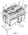
Fig. 1 is a perspective view of an electrical distribution center in an assembled condition. -
Fig. 2 is an exploded perspective view of the electrical distribution center shown inFig. 1 . -
Fig. 3 is an exploded perspective view of the mounting plate secured to a bracket with electrical connectors removed from beneath a mounting plate for clarity. -
Fig. 4 is an exploded perspective view similar to that ofFig. 3 , but with the electrical connectors installed and a lower housing removed. -
Fig. 5 is a bottom view of a portion of the assembled electrical distribution center including the lower housing, the mounting plate, and electrical connectors with the bracket omitted. -
Fig. 6 is an exploded perspective view similar to that ofFig. 4 , but with the lower housing installed and a circuit board removed. -
Fig. 7 is a cross-sectional view of the assembly as shown inFig. 6 , taken through the electrical connectors and with the circuit board installed. -
Fig. 8 is a cross-sectional view through line 8-8 inFig. 1 . - The embodiments, examples and alternatives of the preceding paragraphs, the claims, or the following description and drawings, including any of their various aspects or respective individual features, may be taken independently or in any combination. Features described in connection with one embodiment are applicable to all embodiments, unless such features are incompatible.
- An example
electrical distribution center 10 is shown inFigs. 1 and2 . Theelectrical distribution center 10 includes upper andlower housings circuit board 16. Theupper housing 12 supportselectrical components 18, such asfuses 20 and relays 22 that are electrically connected to thecircuit board 16. An access cover (not shown) may be secured to theupper housing 12 to protect theelectrical components 18. - The
circuit board 16 is electrically engaged withelectrical connectors 26, which include first andsecond connector portions house wire terminals 44 connected towires 42 of a wire bundle 40 (Fig. 2 ). In the example, theelectrical distribution center 10 includes fourelectrical connectors 26, but it should be understood that greater or fewer electrical connectors can be used. - Referring to
Figs. 2 and3 , agrommet 34 supports eachwire bundle 40 with respect to abracket 32 and provides strain relief. Aperimeter wall 45 of thebracket 32 includeswindows 46 that receive thegrommets 34. In one example, lateral edges 48 of thegrommets 34 are slidingly received ingrooves 50 provided by theperimeter wall 45 during assembly after thewire bundle 40 has been passed through thewindow 46. - In the example, the
bracket 32 includes at least one retaining feature configured to interlock with a mountingplate 36, which is used to locate theelectrical connectors 26 in an assembled condition. For example, the retaining feature is provided byperimeter tabs 64 interiorly located on theperimeter wall 45. Anouter periphery 62 of the mountingplate 36 cooperates with theperimeter tabs 64 to lock the mountingplate 36 to thebracket 32, best shown inFig. 3 . Another retaining feature is provided byfingers 68 that cooperate withslots 66 in the mountingplate 36 at or near its center in the example. The mountingplate 36 is secured to thebracket 32 after thegrommets 34 are arranged in thewindows 46 and with theelectrical connectors 26 installed in thebracket 32. - A
fastening arrangement 38 is used to clamp the entire assembly together once all the components of theelectrical distribution center 10 are snapped together in the assembled condition (Fig. 1 ). Thefastening arrangement 38 is centrally located, which better distributes the clamping load across the entireelectrical distribution center 10. Referring toFig. 2 , in one example, thefastening arrangement 38 is provided by afirst fastening element 100, which may be a T-bolt or stud secured to thebracket 32 and located interiorly of thefingers 68. Thefastening arrangement 38 includes asecond fastening element 102, which may be a barrel nut, that threadably engages thefirst fastening element 100 when in the assembled condition. As can be appreciated by the figures, at least one of the first andsecond fastening elements plate 36 outside of theelectrical connectors 26. That is, individual fastening elements are not used for each electrical connector. - The mounting
plate 36, which is aluminum, for example, includes anaperture 52 having aperimeter 54. Theelectrical connectors 26 protrude through theapertures 52 when assembled (Fig. 4 ). Locating structures are provided on theelectrical connector 26 that are captured between theperimeter 54 and thebracket 32 to align and retain theelectrical connectors 26 relative to thebracket 32. - The locating structure may be provided by, for example,
spring arms 58 provided on theelectrical connectors 26 that cooperate withnotches 56 provided in theaperture 52, shown inFigs. 3 ,5 and7 . This configuration provides centering of theelectrical connector 26 with respect to the mountingplate 36. Opposingedges 60 may be provided on theelectrical connectors 26, for example, on thefirst connector portion 28, which may be arranged immediately beneath theunderside 61 of the mountingplate 36 such that theelectrical connector 26 is at least partially obstructed by the mountingplate 36 and cannot be pulled out once the mountingplate 36 has been secured to thebracket 32. - The
electrical connectors 26 are received in pockets 74 in alower side 72 of thelower housing 14 with thelower housing 14 installed onto thebracket 32, as shown inFig. 8 .Flanges 51 that extend from thelower housing 14 are received in thewindows 46 to retain the grommets 34 (Fig. 6 ). - Referring to
Figs. 6-8 , thecircuit board 16 is arranged on theupper side 70 of thelower housing 14.Terminals 78 on thecircuit board 16 include first and second terminal ends 80, 82 respectively extending from opposing sides. The first terminal ends 80 extend throughholes 76 in thelower housing 14 to electrically connect with the wire terminals 44 (now shown) in theelectrical connectors 26 and provide electrical continuity, as best shown inFig. 8 .Recesses 88 are provided on alower side 86 of theupper housing 12 to receive the second terminal ends 82.Terminals 90 from theelectrical components 18 are arranged at anupper side 84 of theupper housing 12 and are electrically connected to the second terminal ends 82. - In operation, the
electrical distribution center 10 is assembled by arranging theelectrical connectors 26 within thebracket 32. In one example, the wire bundles 40 are moved interiorly through thewindows 46 into thebracket 32, and thegrommets 34 are slid into thewindows 46 using the lateral edges 48 andgrooves 50. The mountingplate 36 is snap-fit into thebracket 32 over theelectrical connectors 26 with at least a portion of theelectrical connector 26 extending through theaperture 52. The locating structures on theelectrical connectors 26 cooperate with features on the mountingplate 36, which align and retain theelectrical connectors 26 relative to thebracket 32 using theaperture 52. - The upper and
lower housings circuit board 16. Hooks 92 on theupper housing 12 are snap-fit withcatches 94 provided on thelower housing 14. - The
lower housing 14 is installed onto thebracket 32 over the mountingplate 36 andelectrical connectors 26. Hooks 96 on thebracket 32 are snap-fit withcatches 98 on theupper housing 12. At the same time, thegrommets 34 are retained by theflanges 51 of thelower housing 14 and arranged within thewindows 46. Theelectrical connectors 26 are received within the corresponding pockets 74 in thelower side 72 of thelower housing 14. The first terminal ends 80 ofterminals 78 electrically connect thecircuit board 16 to theelectrical connectors 26. - The
second fastening element 102 is secured to thefirst fastening element 100 to clamp the components of theelectrical distribution center 10 to one another to maintain a secure electrical connection between thecircuit board 16 and theelectrical connectors 26. - The
electrical components 18 are installed at theupper side 84 of theupper housing 12 to electrically connect theelectrical components 18 to thecircuit board 16 and thereby theelectrical connectors 26. An access cover (not shown) is secured to theupper housing 12 over theelectrical components 18. - In the disclosed example, six fasteners are eliminated by providing electrical connector guidance with the mounting plate. This reduces the cost of the electrical distribution center and also reduces assembly time.
- It should be understood that the terms "upper," "lower," "top," "bottom," "side" are used for convenience only and are in no way intended to be limiting. It should also be understood that although a particular component arrangement is disclosed in the illustrated embodiment, other arrangements will benefit herefrom. Although particular step sequences are shown, described, and claimed, it should be understood that steps may be performed in any order, separated or combined unless otherwise indicated and will still benefit from the present invention.
- Although the different examples have specific components shown in the illustrations, embodiments of this invention are not limited to those particular combinations. It is possible to use some of the components or features from one of the examples in combination with features or components from another one of the examples.
Claims (15)
- An electrical distribution center (10) comprising:a bracket (32);a mounting plate (36) is secured to the bracket (32) and includes an aperture (52) having a perimeter (54); andan electrical connector (26) is disposed within the aperture (52) and includes locating structure that is captured between the perimeter (54) and the bracket (32) to align and to retain the electrical connector (26) relative to the bracket (32), wherein the mounting plate (36) includes a plurality of the apertures (52), and a corresponding plurality of the electrical connectors (26) are each arranged in a respective one of the apertures (52), and the bracket (32) includes a first fastening element (100), and comprising a second fastening element (102) that threadingly engages the first fastening element (100) in an assembled condition, at least one of the first and second fastening elements (100, 102) passes through the mounting plate (36) outside of the electrical connectors (26).
- The electrical distribution center (10) according to claim 1, wherein the bracket (32) includes a retaining feature configured to interlock with the mounting plate (36) in an assembled condition.
- The electrical distribution center (10) according to claim 2, wherein the retaining feature includes perimeter tabs (64) that cooperate with an outer periphery (62) of the mounting plate (36).
- The electrical distribution center (10) according to one of the claims 2-3, wherein the retaining feature includes fingers (68) that cooperate with slots (66) in the mounting plate (36).
- The electrical distribution center (10) according to one of the preceding claims, comprising a circuit board (16) arranged between an upper housing (12) and a lower housing (14), the circuit board (16) is electrically engaged with the electrical connectors (26) on a lower side of the lower housing (14).
- The electrical distribution center (10) according to claim 5, comprising electrical components (18) electrically engaged with the circuit board (16) on an upper side of the upper housing (12), wherein a lower side of the upper housing (12) faces an upper side of the lower housing (14), wherein electrical terminals (78) extend from the circuit board (16) into the upper and lower housings (12, 14).
- The electrical distribution center (10) according to one of the claims 5-6, wherein the bracket (32) includes a perimeter wall (45) with a window (46), and comprising a grommet (34) that supports a wire bundle (40) terminating in the electrical connector (26), the grommet (34) is received in the window (46) and is retained in the bracket (32) by the lower housing (14).
- The electrical distribution center (10) according to one of the preceding claims, wherein the locating structure includes spring arms (58) that cooperate with notches (56) provided by the aperture (52).
- The electrical distribution center (10) according to one of the preceding claims, wherein the locating structure includes an edge captured beneath a periphery of the aperture (52).
- A method of assembling an electrical distribution center (10), in particular an electrical distribution center (10) according to one of the preceding claims, comprising the steps of:arranging an electrical connector (26) within a bracket (32);inserting a mounting plate (36) with an aperture (52) into the bracket (32) over the electrical connector (26) to align and retain the electrical connector (26) relative to the bracket (32) with the aperture (52);installing a lower housing (14) onto the bracket (32) over the mounting plate (36) and electrical connectors (26);electrically connecting a circuit board (16) into the electrical connector (26) from an upper side of the lower housing (14);installing the lower housing (14) onto an upper housing (12);electrically connecting electrical components (18) to the circuit board (16) from an upper side of the upper housing (12); andthreading a second fastening element (102) to a first fastening element (100) supported by the bracket (32) to clamp the bracket (32), the mounting plate (36), the electrical connector (26), the upper housing (12), the circuit board (16) and the lower housing (14) to one another to provide an assembled electrical distribution center (10).
- The method according to claim 10, further comprising the step of sliding a grommet (34) that supports a wire bundle (40) terminating in the electrical connector (26) into a window (46) of the bracket (32), and retaining the grommet (34) in the bracket (32) with the lower housing (14).
- The method according to one of the claims 10-11, further comprising the step of snapping the upper and lower housings (12, 14) to one another while snapping the upper housing (12) to the bracket (32).
- The method according to one of the claims 10-12, wherein the first and second fastening elements (100, 102) are arranged outside of the electrical connector (26).
- The method according to one of the claims 10-13, wherein the inserting step includes snapping spring arms (58) on the electrical connector (26) into the aperture (52).
- The method according to one of the claims 10-14, wherein the inserting step includes capturing an edge of the electrical connector (26) with a periphery of the aperture (52).
Applications Claiming Priority (1)
| Application Number | Priority Date | Filing Date | Title |
|---|---|---|---|
| US15/189,576 US9627785B1 (en) | 2016-06-22 | 2016-06-22 | Electrical distribution center |
Publications (2)
| Publication Number | Publication Date |
|---|---|
| EP3260332A1 true EP3260332A1 (en) | 2017-12-27 |
| EP3260332B1 EP3260332B1 (en) | 2019-04-03 |
Family
ID=58772218
Family Applications (1)
| Application Number | Title | Priority Date | Filing Date |
|---|---|---|---|
| EP17177118.1A Active EP3260332B1 (en) | 2016-06-22 | 2017-06-21 | Electrical distribution center |
Country Status (4)
| Country | Link |
|---|---|
| US (1) | US9627785B1 (en) |
| EP (1) | EP3260332B1 (en) |
| KR (1) | KR101898812B1 (en) |
| CN (1) | CN107528182B (en) |
Cited By (1)
| Publication number | Priority date | Publication date | Assignee | Title |
|---|---|---|---|---|
| CN112238826A (en) * | 2019-07-19 | 2021-01-19 | 矢崎总业株式会社 | Protector and wire harness |
Families Citing this family (11)
| Publication number | Priority date | Publication date | Assignee | Title |
|---|---|---|---|---|
| JP6569121B2 (en) * | 2016-10-13 | 2019-09-04 | 住友電装株式会社 | Electrical junction box |
| US10028391B1 (en) * | 2017-07-19 | 2018-07-17 | Delphi Technologies, Inc. | Bussed electrical center |
| US10734758B2 (en) * | 2018-08-09 | 2020-08-04 | Aptiv Technologies Limited | Connector-assembly with strain-relief-device |
| CN111371004B (en) * | 2018-12-25 | 2022-03-29 | 李尔公司 | Electrical assembly for preventing incorrect installation |
| US10763629B1 (en) * | 2019-08-12 | 2020-09-01 | Lear Corporation | Integrated assembly of an electrical conductor, a fuse and a connector |
| DE102020126962B4 (en) * | 2020-01-21 | 2026-01-29 | Hanon Systems | Arrangement for connecting electrical terminals and device for driving a compressor with the arrangement |
| US11251575B2 (en) | 2020-07-09 | 2022-02-15 | Rockwell Automation Technologies, Inc. | Connector alignment and retention panel for modular based system |
| US11936128B2 (en) | 2021-02-09 | 2024-03-19 | Lear Corporation | Electrical unit with offset terminals |
| US20240348028A1 (en) * | 2023-04-12 | 2024-10-17 | Nathan Seibert | Electrical Junction Box Device |
| US12651858B2 (en) | 2023-10-05 | 2026-06-09 | Lear Corporation | Electrical connector that includes multiple terminals |
| DE102023132202A1 (en) * | 2023-11-20 | 2025-05-22 | Leoni Bordnetz-Systeme Gmbh | Mounting of control units |
Citations (11)
| Publication number | Priority date | Publication date | Assignee | Title |
|---|---|---|---|---|
| EP0782233A1 (en) * | 1995-12-28 | 1997-07-02 | Sumitomo Wiring Systems, Ltd. | An electrical connection box for an automotive vehicle |
| US5764487A (en) * | 1996-08-06 | 1998-06-09 | Yazaki Corporation | Junction block with integral printed circuit board and electrical connector for same |
| US5788529A (en) * | 1997-06-09 | 1998-08-04 | General Motors Corporation | Top down electrical distribution center assembly |
| US5971796A (en) * | 1998-06-02 | 1999-10-26 | Yazaki Corporation | Wire harness and connector shroud |
| US7037124B2 (en) * | 2004-02-19 | 2006-05-02 | Tyco Electronics Amp Korea, Ltd. | Junction box for vehicles and method for assembling the same |
| US20110299229A1 (en) * | 2010-05-26 | 2011-12-08 | Delphi Technologies, Inc. | Electrical distribution center |
| WO2013029892A1 (en) * | 2011-08-29 | 2013-03-07 | Mie.S | Base for an electronic board, and associated method for assembling the base |
| WO2013105674A2 (en) * | 2012-01-13 | 2013-07-18 | Yazaki Corporation | Screw block installation structure for a junction box |
| US20130194763A1 (en) * | 2010-10-25 | 2013-08-01 | Korea Electric Terminal Co., Ltd | Board block for vehicles |
| EP2879256A1 (en) * | 2012-09-11 | 2015-06-03 | AutoNetworks Technologies, Ltd. | Electrical connection box |
| DE102015207130A1 (en) * | 2014-04-21 | 2015-10-22 | Yazaki Corporation | Electronic component unit |
Family Cites Families (18)
| Publication number | Priority date | Publication date | Assignee | Title |
|---|---|---|---|---|
| CN1218309A (en) * | 1997-11-25 | 1999-06-02 | 住友电装株式会社 | Electrical connection unit |
| US6027360A (en) * | 1998-06-10 | 2000-02-22 | Yazaki Corporation | Junction block bracket for floating connector attachment |
| JP2001203033A (en) * | 2000-01-20 | 2001-07-27 | Thomas & Betts Corp <T&B> | connector |
| JP2001314015A (en) * | 2000-04-27 | 2001-11-09 | Sumitomo Wiring Syst Ltd | Electrical connection box with connector temporary fixing structure |
| JP2002330525A (en) * | 2001-04-27 | 2002-11-15 | Yazaki Corp | Electrical junction box |
| US6905346B2 (en) * | 2001-10-24 | 2005-06-14 | Fujikura Ltd. | Junction box, connector, and connecting terminal for use in the box and connector |
| US6679708B1 (en) * | 2002-09-10 | 2004-01-20 | Sumitomo Wiring Systems, Ltd. | Vehicle junction box having power distribution center with terminal for jump-starting vehicle |
| KR20060054393A (en) * | 2003-08-01 | 2006-05-22 | 지멘스 악티엔게젤샤프트 | Electronic unit and method of manufacturing the electronic unit |
| JP4176005B2 (en) * | 2003-12-22 | 2008-11-05 | 矢崎総業株式会社 | Waterproof structure of electrical junction box |
| US7727022B2 (en) | 2008-02-14 | 2010-06-01 | Delphi Technologies, Inc. | On harness PCB electrical center |
| US8027168B2 (en) * | 2008-08-13 | 2011-09-27 | Delphi Technologies, Inc. | Electrical center with vertical power bus bar |
| KR200473133Y1 (en) * | 2008-12-29 | 2014-06-13 | 대성전기공업 주식회사 | Junction box for vehicles |
| US7931479B1 (en) * | 2009-11-17 | 2011-04-26 | Delphi Technologies, Inc. | Bussed electrical center with combination electrical and mechanical connection |
| JP5756661B2 (en) * | 2010-09-15 | 2015-07-29 | 住友電装株式会社 | Electrical junction box |
| CN102148271B (en) * | 2011-01-24 | 2012-10-24 | 章丘市太和电器有限公司 | Solar photovoltaic junction box |
| CN102740635A (en) * | 2011-04-14 | 2012-10-17 | 漳州鑫美达汽车零部件有限公司 | Novel central electric box of automobile |
| US9282655B2 (en) | 2012-12-11 | 2016-03-08 | Delphi Technologies, Inc. | Electrical distribution center |
| CN104071099B (en) * | 2014-07-21 | 2016-05-11 | 安徽江淮汽车股份有限公司 | A kind of automobile electrical equipment box |
-
2016
- 2016-06-22 US US15/189,576 patent/US9627785B1/en active Active
-
2017
- 2017-06-16 KR KR1020170076553A patent/KR101898812B1/en active Active
- 2017-06-21 EP EP17177118.1A patent/EP3260332B1/en active Active
- 2017-06-21 CN CN201710475722.6A patent/CN107528182B/en active Active
Patent Citations (11)
| Publication number | Priority date | Publication date | Assignee | Title |
|---|---|---|---|---|
| EP0782233A1 (en) * | 1995-12-28 | 1997-07-02 | Sumitomo Wiring Systems, Ltd. | An electrical connection box for an automotive vehicle |
| US5764487A (en) * | 1996-08-06 | 1998-06-09 | Yazaki Corporation | Junction block with integral printed circuit board and electrical connector for same |
| US5788529A (en) * | 1997-06-09 | 1998-08-04 | General Motors Corporation | Top down electrical distribution center assembly |
| US5971796A (en) * | 1998-06-02 | 1999-10-26 | Yazaki Corporation | Wire harness and connector shroud |
| US7037124B2 (en) * | 2004-02-19 | 2006-05-02 | Tyco Electronics Amp Korea, Ltd. | Junction box for vehicles and method for assembling the same |
| US20110299229A1 (en) * | 2010-05-26 | 2011-12-08 | Delphi Technologies, Inc. | Electrical distribution center |
| US20130194763A1 (en) * | 2010-10-25 | 2013-08-01 | Korea Electric Terminal Co., Ltd | Board block for vehicles |
| WO2013029892A1 (en) * | 2011-08-29 | 2013-03-07 | Mie.S | Base for an electronic board, and associated method for assembling the base |
| WO2013105674A2 (en) * | 2012-01-13 | 2013-07-18 | Yazaki Corporation | Screw block installation structure for a junction box |
| EP2879256A1 (en) * | 2012-09-11 | 2015-06-03 | AutoNetworks Technologies, Ltd. | Electrical connection box |
| DE102015207130A1 (en) * | 2014-04-21 | 2015-10-22 | Yazaki Corporation | Electronic component unit |
Cited By (3)
| Publication number | Priority date | Publication date | Assignee | Title |
|---|---|---|---|---|
| CN112238826A (en) * | 2019-07-19 | 2021-01-19 | 矢崎总业株式会社 | Protector and wire harness |
| EP3766740A1 (en) * | 2019-07-19 | 2021-01-20 | Yazaki Corporation | Protector and wire harness |
| CN112238826B (en) * | 2019-07-19 | 2023-09-05 | 矢崎总业株式会社 | Protector and wire harness |
Also Published As
| Publication number | Publication date |
|---|---|
| CN107528182B (en) | 2019-07-23 |
| US9627785B1 (en) | 2017-04-18 |
| KR101898812B1 (en) | 2018-09-13 |
| CN107528182A (en) | 2017-12-29 |
| EP3260332B1 (en) | 2019-04-03 |
| KR20180000305A (en) | 2018-01-02 |
Similar Documents
| Publication | Publication Date | Title |
|---|---|---|
| EP3260332B1 (en) | Electrical distribution center | |
| CN112928715B (en) | Electrical connection box and wire harness | |
| US6547572B1 (en) | Integrated and flexible power distribution assembly | |
| US10699866B2 (en) | Modular fuse holder and arrangement and connection thereof | |
| US4923411A (en) | External connection structure of electric connection box | |
| US20090067122A1 (en) | Power distribution bus bar | |
| US20040264113A1 (en) | Smart junction box for automobile | |
| US7708596B2 (en) | Automotive electrical connector system and method of assembling same | |
| JP2003009347A (en) | Electrical junction box | |
| US9788441B2 (en) | Switching device | |
| US3146052A (en) | Vehicle-panel connector | |
| US20200090894A1 (en) | High current fuse block | |
| EP3117496B1 (en) | Bracket for and method of forming a wire harness assembly | |
| US20040129826A1 (en) | Simplified interconnect for center of wide body aircraft | |
| EP1544045A1 (en) | Door module for a vehicle | |
| US5543581A (en) | Branching connection box for electrical circuits | |
| EP3437928B1 (en) | Bussed electrical center | |
| US6220901B1 (en) | Electric motor terminal board assembly | |
| GB2342512A (en) | Connector for grounding electrical components | |
| US11102903B2 (en) | Formed enclosure part and electronic subassembly | |
| JP3693231B2 (en) | Wiring harness wiring structure for vehicles | |
| JP7593971B2 (en) | Vehicle-mounted electrical junction box | |
| JPH0654607B2 (en) | Wire harness device for instrument panel | |
| EP3611750B1 (en) | Space saving electrical devices arrangement for installation on a mounting rail and connector devices for a space saving electrical devices arrangement for installation on a mounting rail or mounting plate | |
| JP6820896B2 (en) | Battery unit |
Legal Events
| Date | Code | Title | Description |
|---|---|---|---|
| PUAI | Public reference made under article 153(3) epc to a published international application that has entered the european phase |
Free format text: ORIGINAL CODE: 0009012 |
|
| STAA | Information on the status of an ep patent application or granted ep patent |
Free format text: STATUS: THE APPLICATION HAS BEEN PUBLISHED |
|
| AK | Designated contracting states |
Kind code of ref document: A1 Designated state(s): AL AT BE BG CH CY CZ DE DK EE ES FI FR GB GR HR HU IE IS IT LI LT LU LV MC MK MT NL NO PL PT RO RS SE SI SK SM TR |
|
| AX | Request for extension of the european patent |
Extension state: BA ME |
|
| STAA | Information on the status of an ep patent application or granted ep patent |
Free format text: STATUS: REQUEST FOR EXAMINATION WAS MADE |
|
| 17P | Request for examination filed |
Effective date: 20180627 |
|
| RBV | Designated contracting states (corrected) |
Designated state(s): AL AT BE BG CH CY CZ DE DK EE ES FI FR GB GR HR HU IE IS IT LI LT LU LV MC MK MT NL NO PL PT RO RS SE SI SK SM TR |
|
| GRAP | Despatch of communication of intention to grant a patent |
Free format text: ORIGINAL CODE: EPIDOSNIGR1 |
|
| STAA | Information on the status of an ep patent application or granted ep patent |
Free format text: STATUS: GRANT OF PATENT IS INTENDED |
|
| RIC1 | Information provided on ipc code assigned before grant |
Ipc: H05K 7/02 20060101ALI20181024BHEP Ipc: H01R 13/50 20060101ALI20181024BHEP Ipc: B60R 16/02 20060101AFI20181024BHEP |
|
| INTG | Intention to grant announced |
Effective date: 20181112 |
|
| RIN1 | Information on inventor provided before grant (corrected) |
Inventor name: MORALES, JESUS R. Inventor name: MELCHOR SAUCEDO, GUSTAVO ERIC |
|
| RAP1 | Party data changed (applicant data changed or rights of an application transferred) |
Owner name: APTIV TECHNOLOGIES LIMITED |
|
| GRAS | Grant fee paid |
Free format text: ORIGINAL CODE: EPIDOSNIGR3 |
|
| GRAA | (expected) grant |
Free format text: ORIGINAL CODE: 0009210 |
|
| STAA | Information on the status of an ep patent application or granted ep patent |
Free format text: STATUS: THE PATENT HAS BEEN GRANTED |
|
| AK | Designated contracting states |
Kind code of ref document: B1 Designated state(s): AL AT BE BG CH CY CZ DE DK EE ES FI FR GB GR HR HU IE IS IT LI LT LU LV MC MK MT NL NO PL PT RO RS SE SI SK SM TR |
|
| REG | Reference to a national code |
Ref country code: GB Ref legal event code: FG4D |
|
| REG | Reference to a national code |
Ref country code: CH Ref legal event code: EP Ref country code: AT Ref legal event code: REF Ref document number: 1115335 Country of ref document: AT Kind code of ref document: T Effective date: 20190415 |
|
| REG | Reference to a national code |
Ref country code: DE Ref legal event code: R096 Ref document number: 602017003042 Country of ref document: DE |
|
| REG | Reference to a national code |
Ref country code: IE Ref legal event code: FG4D |
|
| REG | Reference to a national code |
Ref country code: NL Ref legal event code: MP Effective date: 20190403 |
|
| REG | Reference to a national code |
Ref country code: LT Ref legal event code: MG4D |
|
| REG | Reference to a national code |
Ref country code: AT Ref legal event code: MK05 Ref document number: 1115335 Country of ref document: AT Kind code of ref document: T Effective date: 20190403 |
|
| PG25 | Lapsed in a contracting state [announced via postgrant information from national office to epo] |
Ref country code: NL Free format text: LAPSE BECAUSE OF FAILURE TO SUBMIT A TRANSLATION OF THE DESCRIPTION OR TO PAY THE FEE WITHIN THE PRESCRIBED TIME-LIMIT Effective date: 20190403 |
|
| PG25 | Lapsed in a contracting state [announced via postgrant information from national office to epo] |
Ref country code: ES Free format text: LAPSE BECAUSE OF FAILURE TO SUBMIT A TRANSLATION OF THE DESCRIPTION OR TO PAY THE FEE WITHIN THE PRESCRIBED TIME-LIMIT Effective date: 20190403 Ref country code: AL Free format text: LAPSE BECAUSE OF FAILURE TO SUBMIT A TRANSLATION OF THE DESCRIPTION OR TO PAY THE FEE WITHIN THE PRESCRIBED TIME-LIMIT Effective date: 20190403 Ref country code: SE Free format text: LAPSE BECAUSE OF FAILURE TO SUBMIT A TRANSLATION OF THE DESCRIPTION OR TO PAY THE FEE WITHIN THE PRESCRIBED TIME-LIMIT Effective date: 20190403 Ref country code: PT Free format text: LAPSE BECAUSE OF FAILURE TO SUBMIT A TRANSLATION OF THE DESCRIPTION OR TO PAY THE FEE WITHIN THE PRESCRIBED TIME-LIMIT Effective date: 20190803 Ref country code: HR Free format text: LAPSE BECAUSE OF FAILURE TO SUBMIT A TRANSLATION OF THE DESCRIPTION OR TO PAY THE FEE WITHIN THE PRESCRIBED TIME-LIMIT Effective date: 20190403 Ref country code: LT Free format text: LAPSE BECAUSE OF FAILURE TO SUBMIT A TRANSLATION OF THE DESCRIPTION OR TO PAY THE FEE WITHIN THE PRESCRIBED TIME-LIMIT Effective date: 20190403 Ref country code: CZ Free format text: LAPSE BECAUSE OF FAILURE TO SUBMIT A TRANSLATION OF THE DESCRIPTION OR TO PAY THE FEE WITHIN THE PRESCRIBED TIME-LIMIT Effective date: 20190403 Ref country code: FI Free format text: LAPSE BECAUSE OF FAILURE TO SUBMIT A TRANSLATION OF THE DESCRIPTION OR TO PAY THE FEE WITHIN THE PRESCRIBED TIME-LIMIT Effective date: 20190403 Ref country code: NO Free format text: LAPSE BECAUSE OF FAILURE TO SUBMIT A TRANSLATION OF THE DESCRIPTION OR TO PAY THE FEE WITHIN THE PRESCRIBED TIME-LIMIT Effective date: 20190703 |
|
| PG25 | Lapsed in a contracting state [announced via postgrant information from national office to epo] |
Ref country code: RS Free format text: LAPSE BECAUSE OF FAILURE TO SUBMIT A TRANSLATION OF THE DESCRIPTION OR TO PAY THE FEE WITHIN THE PRESCRIBED TIME-LIMIT Effective date: 20190403 Ref country code: PL Free format text: LAPSE BECAUSE OF FAILURE TO SUBMIT A TRANSLATION OF THE DESCRIPTION OR TO PAY THE FEE WITHIN THE PRESCRIBED TIME-LIMIT Effective date: 20190403 Ref country code: BG Free format text: LAPSE BECAUSE OF FAILURE TO SUBMIT A TRANSLATION OF THE DESCRIPTION OR TO PAY THE FEE WITHIN THE PRESCRIBED TIME-LIMIT Effective date: 20190703 Ref country code: LV Free format text: LAPSE BECAUSE OF FAILURE TO SUBMIT A TRANSLATION OF THE DESCRIPTION OR TO PAY THE FEE WITHIN THE PRESCRIBED TIME-LIMIT Effective date: 20190403 Ref country code: GR Free format text: LAPSE BECAUSE OF FAILURE TO SUBMIT A TRANSLATION OF THE DESCRIPTION OR TO PAY THE FEE WITHIN THE PRESCRIBED TIME-LIMIT Effective date: 20190704 |
|
| PG25 | Lapsed in a contracting state [announced via postgrant information from national office to epo] |
Ref country code: IS Free format text: LAPSE BECAUSE OF FAILURE TO SUBMIT A TRANSLATION OF THE DESCRIPTION OR TO PAY THE FEE WITHIN THE PRESCRIBED TIME-LIMIT Effective date: 20190803 Ref country code: AT Free format text: LAPSE BECAUSE OF FAILURE TO SUBMIT A TRANSLATION OF THE DESCRIPTION OR TO PAY THE FEE WITHIN THE PRESCRIBED TIME-LIMIT Effective date: 20190403 |
|
| REG | Reference to a national code |
Ref country code: DE Ref legal event code: R097 Ref document number: 602017003042 Country of ref document: DE |
|
| PG25 | Lapsed in a contracting state [announced via postgrant information from national office to epo] |
Ref country code: DK Free format text: LAPSE BECAUSE OF FAILURE TO SUBMIT A TRANSLATION OF THE DESCRIPTION OR TO PAY THE FEE WITHIN THE PRESCRIBED TIME-LIMIT Effective date: 20190403 Ref country code: MC Free format text: LAPSE BECAUSE OF FAILURE TO SUBMIT A TRANSLATION OF THE DESCRIPTION OR TO PAY THE FEE WITHIN THE PRESCRIBED TIME-LIMIT Effective date: 20190403 Ref country code: RO Free format text: LAPSE BECAUSE OF FAILURE TO SUBMIT A TRANSLATION OF THE DESCRIPTION OR TO PAY THE FEE WITHIN THE PRESCRIBED TIME-LIMIT Effective date: 20190403 Ref country code: SK Free format text: LAPSE BECAUSE OF FAILURE TO SUBMIT A TRANSLATION OF THE DESCRIPTION OR TO PAY THE FEE WITHIN THE PRESCRIBED TIME-LIMIT Effective date: 20190403 Ref country code: EE Free format text: LAPSE BECAUSE OF FAILURE TO SUBMIT A TRANSLATION OF THE DESCRIPTION OR TO PAY THE FEE WITHIN THE PRESCRIBED TIME-LIMIT Effective date: 20190403 |
|
| PLBE | No opposition filed within time limit |
Free format text: ORIGINAL CODE: 0009261 |
|
| STAA | Information on the status of an ep patent application or granted ep patent |
Free format text: STATUS: NO OPPOSITION FILED WITHIN TIME LIMIT |
|
| PG25 | Lapsed in a contracting state [announced via postgrant information from national office to epo] |
Ref country code: SM Free format text: LAPSE BECAUSE OF FAILURE TO SUBMIT A TRANSLATION OF THE DESCRIPTION OR TO PAY THE FEE WITHIN THE PRESCRIBED TIME-LIMIT Effective date: 20190403 Ref country code: IT Free format text: LAPSE BECAUSE OF FAILURE TO SUBMIT A TRANSLATION OF THE DESCRIPTION OR TO PAY THE FEE WITHIN THE PRESCRIBED TIME-LIMIT Effective date: 20190403 |
|
| 26N | No opposition filed |
Effective date: 20200106 |
|
| REG | Reference to a national code |
Ref country code: BE Ref legal event code: MM Effective date: 20190630 |
|
| PG25 | Lapsed in a contracting state [announced via postgrant information from national office to epo] |
Ref country code: TR Free format text: LAPSE BECAUSE OF FAILURE TO SUBMIT A TRANSLATION OF THE DESCRIPTION OR TO PAY THE FEE WITHIN THE PRESCRIBED TIME-LIMIT Effective date: 20190403 |
|
| PG25 | Lapsed in a contracting state [announced via postgrant information from national office to epo] |
Ref country code: IE Free format text: LAPSE BECAUSE OF NON-PAYMENT OF DUE FEES Effective date: 20190621 |
|
| PG25 | Lapsed in a contracting state [announced via postgrant information from national office to epo] |
Ref country code: LU Free format text: LAPSE BECAUSE OF NON-PAYMENT OF DUE FEES Effective date: 20190621 Ref country code: BE Free format text: LAPSE BECAUSE OF NON-PAYMENT OF DUE FEES Effective date: 20190630 Ref country code: SI Free format text: LAPSE BECAUSE OF FAILURE TO SUBMIT A TRANSLATION OF THE DESCRIPTION OR TO PAY THE FEE WITHIN THE PRESCRIBED TIME-LIMIT Effective date: 20190403 |
|
| REG | Reference to a national code |
Ref country code: CH Ref legal event code: PL |
|
| PG25 | Lapsed in a contracting state [announced via postgrant information from national office to epo] |
Ref country code: CH Free format text: LAPSE BECAUSE OF NON-PAYMENT OF DUE FEES Effective date: 20200630 Ref country code: LI Free format text: LAPSE BECAUSE OF NON-PAYMENT OF DUE FEES Effective date: 20200630 |
|
| PG25 | Lapsed in a contracting state [announced via postgrant information from national office to epo] |
Ref country code: CY Free format text: LAPSE BECAUSE OF FAILURE TO SUBMIT A TRANSLATION OF THE DESCRIPTION OR TO PAY THE FEE WITHIN THE PRESCRIBED TIME-LIMIT Effective date: 20190403 |
|
| PG25 | Lapsed in a contracting state [announced via postgrant information from national office to epo] |
Ref country code: MT Free format text: LAPSE BECAUSE OF FAILURE TO SUBMIT A TRANSLATION OF THE DESCRIPTION OR TO PAY THE FEE WITHIN THE PRESCRIBED TIME-LIMIT Effective date: 20190403 Ref country code: HU Free format text: LAPSE BECAUSE OF FAILURE TO SUBMIT A TRANSLATION OF THE DESCRIPTION OR TO PAY THE FEE WITHIN THE PRESCRIBED TIME-LIMIT; INVALID AB INITIO Effective date: 20170621 |
|
| PG25 | Lapsed in a contracting state [announced via postgrant information from national office to epo] |
Ref country code: MK Free format text: LAPSE BECAUSE OF FAILURE TO SUBMIT A TRANSLATION OF THE DESCRIPTION OR TO PAY THE FEE WITHIN THE PRESCRIBED TIME-LIMIT Effective date: 20190403 |
|
| P01 | Opt-out of the competence of the unified patent court (upc) registered |
Effective date: 20230420 |
|
| REG | Reference to a national code |
Ref country code: DE Ref legal event code: R081 Ref document number: 602017003042 Country of ref document: DE Owner name: APTIV TECHNOLOGIES AG, CH Free format text: FORMER OWNER: APTIV TECHNOLOGIES LIMITED, ST. MICHAEL, BB |
|
| REG | Reference to a national code |
Ref country code: GB Ref legal event code: 732E Free format text: REGISTERED BETWEEN 20260507 AND 20260513 |
|
| REG | Reference to a national code |
Ref country code: GB Ref legal event code: 732E Free format text: REGISTERED BETWEEN 20260521 AND 20260527 |
|
| PGFP | Annual fee paid to national office [announced via postgrant information from national office to epo] |
Ref country code: GB Payment date: 20260615 Year of fee payment: 10 |
|
| PGFP | Annual fee paid to national office [announced via postgrant information from national office to epo] |
Ref country code: DE Payment date: 20260522 Year of fee payment: 10 |
|
| PGFP | Annual fee paid to national office [announced via postgrant information from national office to epo] |
Ref country code: FR Payment date: 20260615 Year of fee payment: 10 |