EP3766740A1 - Protector and wire harness - Google Patents
Protector and wire harness Download PDFInfo
- Publication number
- EP3766740A1 EP3766740A1 EP20183956.0A EP20183956A EP3766740A1 EP 3766740 A1 EP3766740 A1 EP 3766740A1 EP 20183956 A EP20183956 A EP 20183956A EP 3766740 A1 EP3766740 A1 EP 3766740A1
- Authority
- EP
- European Patent Office
- Prior art keywords
- guide
- paired
- opposed
- portions
- protector
- Prior art date
- Legal status (The legal status is an assumption and is not a legal conclusion. Google has not performed a legal analysis and makes no representation as to the accuracy of the status listed.)
- Granted
Links
- 230000001012 protector Effects 0.000 title claims abstract description 166
- 230000007246 mechanism Effects 0.000 claims abstract description 91
- 238000003780 insertion Methods 0.000 description 29
- 230000037431 insertion Effects 0.000 description 29
- 238000009413 insulation Methods 0.000 description 4
- 239000002184 metal Substances 0.000 description 3
- 239000000463 material Substances 0.000 description 2
- 239000011347 resin Substances 0.000 description 2
- 229920005989 resin Polymers 0.000 description 2
- 238000004891 communication Methods 0.000 description 1
- 239000004020 conductor Substances 0.000 description 1
- 238000010276 construction Methods 0.000 description 1
- 238000000034 method Methods 0.000 description 1
- 238000012986 modification Methods 0.000 description 1
- 230000004048 modification Effects 0.000 description 1
Images


Classifications
-
- B—PERFORMING OPERATIONS; TRANSPORTING
- B60—VEHICLES IN GENERAL
- B60R—VEHICLES, VEHICLE FITTINGS, OR VEHICLE PARTS, NOT OTHERWISE PROVIDED FOR
- B60R16/00—Electric or fluid circuits specially adapted for vehicles and not otherwise provided for; Arrangement of elements of electric or fluid circuits specially adapted for vehicles and not otherwise provided for
- B60R16/02—Electric or fluid circuits specially adapted for vehicles and not otherwise provided for; Arrangement of elements of electric or fluid circuits specially adapted for vehicles and not otherwise provided for electric constitutive elements
- B60R16/0207—Wire harnesses
- B60R16/0215—Protecting, fastening and routing means therefor
-
- H—ELECTRICITY
- H01—ELECTRIC ELEMENTS
- H01B—CABLES; CONDUCTORS; INSULATORS; SELECTION OF MATERIALS FOR THEIR CONDUCTIVE, INSULATING OR DIELECTRIC PROPERTIES
- H01B7/00—Insulated conductors or cables characterised by their form
- H01B7/0045—Cable-harnesses
-
- H—ELECTRICITY
- H02—GENERATION; CONVERSION OR DISTRIBUTION OF ELECTRIC POWER
- H02G—INSTALLATION OF ELECTRIC CABLES OR LINES, OR OF COMBINED OPTICAL AND ELECTRIC CABLES OR LINES
- H02G3/00—Installations of electric cables or lines or protective tubing therefor in or on buildings, equivalent structures or vehicles
- H02G3/02—Details
- H02G3/04—Protective tubing or conduits, e.g. cable ladders or cable troughs
- H02G3/0406—Details thereof
- H02G3/0418—Covers or lids; Their fastenings
Definitions
- the present invention relates to a protector and a wire harness.
- a protector disclosed in Japanese Patent Application Laid-open No. 2006-74843 which includes a protector main body having a tub shape and a lid separate from the protector main body.
- a protector main body having a tub shape and a lid separate from the protector main body.
- a large number of lock lug locking frames are formed in protruding manners at intervals in a length direction at the opposed positions on opposite sides along upper ends of outer faces of the side walls.
- a large number of lock chips having lock lugs at lower ends are formed in downward protruding manners at intervals along the length direction.
- the positions of the lock chips of the lid and the positions of the lock locking frames of the protector main body are opposed to each other.
- the protector described in above-mentioned Japanese Patent Application Laid-open No. 2006-74843 is desired to have such a structure that the protector can be assembled more reliably, for example.
- the present invention has been made with the above circumstances in view and its object is to provide a protector and a wire harness that can be assembled properly.
- a protector according to one aspect of the present invention includes a protector main body including a base, paired opposed wall portions protruding from the base and opposed to each other along an opposed direction, a routing space that is formed by the base and the paired opposed wall portions and through which a wire is routed, and an opening that is formed by end portions of the paired opposed wall portions on an opposite side from the base and that opens on one side in a protruding direction of the opposed wall portions with respect to the base; a lid member that closes the opening; a locking mechanism including a locking hole that is formed in the lid member and opens on opposite sides in the protruding direction and a locking lug portion that is positioned at the end portion of the opposed wall portion on a side of the opening and that is locked to the locking hole, the locking mechanism locking the protector main body and the lid member to each other in a correct position where the lid member closes the opening; and paired guide mechanisms including paired guide chips respectively positioned at opposite end portions in the opposed direction of the lid
- each of the paired guide holes is adjacent to the locking hole in an adjacent direction intersecting the protruding direction and the opposed direction when the lid member is disposed in the correct position for closing the opening.
- each of the paired guide holes includes a plate-shaped portion extending along the adjacent direction intersecting the protruding direction and the opposed direction, a support portion that supports opposite end portions of the plate-shaped portion, and a guide space that is positioned between the opposed wall portion and the plate-shaped portion in the opposed direction and into which the guide chip is inserted, an inner face of the plate-shaped portion opposed to the opposed wall portion is inclined with respect to the protruding direction such that the guide space gradually widens from a side of the base toward the side of the opening, and a width along the opposed direction of the inclined inner face of one of the paired guide mechanisms is greater than a width along the opposed direction of the inclined inner face of the other guide mechanism in the paired guide mechanisms.
- a wire harness includes a wire having conductivity; and a protector that is mounted to the wire and protects the wire, wherein the protector includes a protector main body having a base, paired opposed wall portions protruding from the base and opposed to each other along an opposed direction, a routing space which is formed by the base and the paired opposed wall portions and through which the wire is routed, and an opening that is formed by end portions of the paired opposed wall portions on an opposite side from the base and that opens on one side in a protruding direction of the opposed wall portions with respect to the base, a lid member that closes the opening, a locking mechanism having a locking hole that is formed in the lid member and opens on opposite sides in the protruding direction and a locking lug portion that is positioned at the end portion of the opposed wall portion on a side of the opening and that is locked to the locking hole, the locking mechanism locking the protector main body and the lid member to each other in a correct position where the lid member
- Wires W are shown by two-dot chain lines in FIGS. 1 and 2 described below and are not shown in the other figures.
- the first direction will be referred to as an "axial direction X”
- the second direction will be referred to as a “height direction Y”
- the third direction will be referred to as a "width direction Z”.
- the axial direction X, the height direction Y, and the width direction Z are orthogonal to each other (intersecting each other).
- the height direction Y typically corresponds to a stacking direction in which a protector main body 10 and a lid member 20 are stacked, corresponds to a protruding direction in which opposed wall portions 12a, 12b, 12c, 12d protrude with respect to a base 11, and corresponds to a protruding direction in which lid side wall portions 22 protrude with respect to a lid portion 21.
- the width direction Z typically corresponds to an opposed direction in which the paired first opposed wall portions (paired opposed wall portions) 12a, 12b are opposed to each other and corresponds to an opposed direction in which paired first lid side wall portions 22a, 22b are opposed to each other.
- the axial direction X typically corresponds to a direction in which locking holes 31 and guide holes 42A, 42B are adjacent to each other and corresponds to a direction in which the paired first opposed wall portions 12a, 12b extend respectively.
- FIGS. 7 , 10 , 11 , 8 , 12 , and 13 are sectional views in a plane including the height direction Y and the width direction Z (sectional views in a plane orthogonal to the axial direction X).
- the respective directions used in the following description are directions when respective portions of a protector 1 are assembled unless otherwise specified.
- the protector 1 according to the present embodiment and shown in FIGS. 1 , 2 , and 3 is mounted into a wire harness WH1 mounted to a vehicle such as an automobile and covers the wires W having conductivity to protect the wires W.
- the wire harness WH1 is formed as a part assembly by binding the plurality of wires W used for power supply and signal communication such that the plurality of wires W are connected to the respective devices by use of connectors or the like.
- the wire harness WH1 includes the wires W having the conductivity and the protector 1 that is mounted to the wires W to protect the wires W.
- the wires W are formed by metal rods, electric wires, electric wire bundles, or the like, for example.
- the metal rods are rod-shaped members that have conductivity and are covered with sheaths, having insulation properties, from outside.
- the electric wires are conductors (cable cores) formed by a plurality of metal wires that have conductivity and are covered with sheaths, having insulation properties, from outside.
- the electric wire bundles are the electric wires that are bundled.
- the wire harness WH1 in the embodiment achieves a structure capable of properly assembling the protector 1 that is mounted to the wires W, by providing locking mechanisms 30 and paired guide mechanisms 40A, 40B to the protector 1. A structure of the protector 1 will be described below in detail with reference to the respective figures.
- the wire harness WH1 may also include an electric connection box, grommets, fixtures, connectors, and the like.
- the protector 1 is made of resin material having an insulation property and formed in a substantially tubular shape.
- the wires W are routed while bent in a substantially L shape.
- the wires W are not necessarily routed in this manner and may be routed straight.
- the protector 1 includes the protector main body 10, the lid member 20, the locking mechanisms 30, the pair of guide mechanisms 40A, 40B, and a cover 50.
- the protector main body 10 and the lid member 20 are formed separately and mounted to each other by use of the locking mechanisms 30.
- the protector 1 is formed into the substantially L-shaped tubular shape as a whole by mounting of the protector main body 10 and the lid member 20 to each other.
- the protector 1 in the embodiment achieves the structure capable of properly mounting the lid member 20 to the protector main body 10 by use of the pair of guide mechanisms 40A, 40B.
- the protector 1 further includes a guide mechanism 40C provided separately from the pair of guide mechanisms 40A, 40B.
- a structure of the protector 1 will be described below in detail with reference to the respective figures.
- the protector main body 10 Through the protector main body 10, the wires W are inserted and routed.
- the protector main body 10 is formed in a gutter shape open at one end portion in the axial direction X, opposite end portions in the width direction Z, and one end portion in the height direction Y.
- the wires W are inserted along the axial direction X and the width direction Z.
- the protector main body 10 has the base 11 and main body side wall portions 12.
- the protector main body 10 is formed to include the base 11, a routing space 13 formed by the main body side wall portions 12, insertion openings 14, and an opening/closing opening 15.
- the protector main body 10 is formed in the shape of the substantially L-shaped tub as described above with the base 11 and the main body side wall portions 12 integrated with each other.
- the base 11 is a bottom body for defining the routing space 13 as an inner space of the protector main body 10.
- the base 11 is formed in a substantially plate shape with a plate thickness direction oriented in the height direction Y.
- the base 11 has a first base (base) 11a extending in the axial direction X and a second base 11b extending in the width direction Z.
- the first base 11a has a predetermined width in the width direction Z for routing of the wires W.
- the second base 11b has a predetermined width in the axial direction X for routing of the wires W.
- the base 11 is formed in a substantially L shape with the first base 11a and the second base 11b formed integrally.
- the main body side wall portions 12 are wall bodies for defining the routing space 13 as the inner space of the protector main body 10.
- the main body side wall portions 12 include the paired first opposed wall portions 12a, 12b (the paired opposed wall portions) opposed to each other and the paired second opposed wall portions 12c, 12d opposed to each other, the first and second opposed wall portions 12a, 12b, 12c, 12d formed to protrude along the height direction Y from the base 11.
- Both of the paired first opposed wall portions 12a, 12b are formed in substantially plate shapes with plate thickness directions oriented in the width direction Z.
- the respective first opposed wall portions 12a, 12b extend along the axial direction X and the height direction Y.
- the paired first opposed wall portions 12a, 12b are provided on opposite sides of the first base 11a in the width direction Z and positioned at an interval and opposed to each other along the width direction Z.
- the paired first opposed wall portions 12a, 12b are respectively provided at opposite edges in the width direction Z of the first base 11a and extend from one end portion to the other end portion of the first base 11a along the axial direction X.
- the first base 11a is positioned between the paired first opposed wall portions 12a, 12b in the width direction Z and opposite end portions in the width direction Z of the first base 11a are connected to the first opposed wall portions 12a, 12b, respectively.
- the paired first opposed wall portions 12a, 12b stand on the same side in the height direction Y of the first base 11a.
- the one first opposed wall portion 12a and the other first opposed wall portion 12b have substantially equal lengths along the height direction Y and the other first opposed wall portion 12b has a greater length along the axial direction X than the one first opposed wall portion 12a.
- Both of the paired second opposed wall portions 12c, 12d are formed in substantially plate shapes with plate thickness directions oriented in the axial direction X.
- the respective second opposed wall portions 12c, 12d extend along the width direction Z and the height direction Y.
- the paired second opposed wall portions 12c, 12d are provided on opposite sides of the second base 11b in the axial direction X and positioned at an interval and opposed to each other along the axial direction X.
- the paired second opposed wall portions 12c, 12d are respectively provided at opposite edges in the axial direction X of the second base 11b and extend from one end portion to the other end portion of the second base 11b along the width direction Z.
- the second base 11b is positioned between the paired second opposed wall portions 12c, 12d in the axial direction X and opposite end portions in the axial direction X of the second base 11b are connected to the second opposed wall portions 12c, 12d, respectively.
- the paired second opposed wall portions 12c, 12d stand on the same side in the height direction Y of the second base 11b.
- the one second opposed wall portion 12c and the other second opposed wall portion 12d have substantially equal lengths along the height direction Y and the other second opposed wall portion 12d has a greater length along the width direction Z than the one second opposed wall portion 12c.
- the routing space 13, the plurality of insertion openings 14, and the opening/closing opening 15 are formed by the base 11 and the main body side wall portions 12.
- the routing space 13 is a space through which the wires W are routed along the axial direction X and the width direction Z.
- the routing space 13 is formed as the inner space surrounded with the base 11 and the main body side wall portions 12.
- the insertion openings 14 are openings through which the wires W are inserted into the routing space 13.
- the insertion openings 14 include a first insertion opening 14a formed at one end portion in the axial direction X by the paired first opposed wall portions 12a, 12b and the first base 11a.
- the first insertion opening 14a opens along the width direction Z and the height direction Y as shown in FIG. 1 .
- the insertion openings 14 include a second insertion opening 14b and a third insertion opening 14c formed at opposite end portions in the width direction Z by the paired second opposed wall portions 12c, 12d and the second base 11b.
- the second insertion opening 14b is positioned at the one end portion in the width direction Z and opens along the axial direction X and the height direction Y.
- the third insertion opening 14c is positioned at the other end portion in the width direction Z and opens along the axial direction X and the height direction Y (see FIG. 2 ). As shown in FIG.
- the opening/closing opening 15 is an opening that opens the routing space 13 to an outside and is the opening that is closed with the lid member 20.
- the opening/closing opening 15 is opened when the wires W are inserted through the routing space 13 and is closed with the lid member 20 after the wires W are inserted through the routing space 13, for example.
- the opening/closing opening 15 is formed by end portions of the respective opposed wall portions 12a, 12b, 12c, 12d on an opposite from the base 11.
- the opening/closing opening 15 is open on one side along the height direction Y of the respective opposed wall portions 12a, 12b, 12c, 12d, i.e., on the opposite side from the base 11.
- the lid member 20 is mounted to the protector main body 10 to close (block) the opening/closing opening 15 formed in the protector main body 10.
- the lid member 20 has a lid portion 21 and lid side wall portions 22 as shown in FIGS. 1 , 2 , 3 , and 4 .
- the lid member 20 is formed in a shape of a substantially L-shaped plate corresponding to a shape of the protector main body 10 by the lid portion 21 and the lid side wall portions 22 integrated with each other.
- the lid portion 21 is a lid body that closes the opening/closing opening 15 of the protector main body 10 and defines the routing space 13.
- the lid portion 21 is formed in a substantially plate shape with a plate thickness direction oriented in the height direction Y.
- the lid portion 21 has a first lid portion 21a opposed to the first base 11a in the height direction Y and extending in the axial direction X and a second lid portion 21b opposed to the second base 11b in the height direction Y and extending in the width direction Z.
- the first lid portion 21a has a predetermined width in the width direction Z so as to be able to close the routing space 13.
- the second lid portion 21b has a predetermined width in the axial direction X so as to be able to close the routing space 13.
- the lid portion 21 is formed in a substantially L shape with the first lid portion 21a and the second lid portion 21b formed integrally.
- the lid side wall portions 22 are overlapping bodies that overlap the main body side wall portions 12 of the protector main body 10 and include paired first lid side wall portions 22a, 22b opposed to each other and paired second side wall portions opposed to each other.
- the paired first lid side wall portions 22a, 22b are formed to protrude along the height direction Y from the first lid portion 21a.
- both of the first lid side wall portions 22a, 22b are formed in substantially plate shapes with plate thickness directions oriented in the width direction Z.
- the paired first lid side wall portions 22a, 22b extend along the axial direction X and the height direction Y.
- the paired first lid side wall portions 22a, 22b are provided on opposite sides of the first lid portion 21a in the width direction Z and positioned at an interval and opposed to each other along the width direction Z.
- the paired first lid side wall portions 22a, 22b are respectively provided at opposite edges in the width direction Z of the first lid portion 21a and extend from one end portion to the other end portion of the first lid portion 21a along the axial direction X.
- the first lid portion 21a is positioned between the paired first lid side wall portions 22a, 22b in the width direction Z and opposite end portions in the width direction Z of the first lid portion 21a are connected to the first lid side wall portions 22a, 22b, respectively.
- the paired first lid side wall portions 22a, 22b stand on the same side in the height direction Y of the first lid portion 21a.
- the first lid side wall portions 22a, 22b are formed to protrude toward the protector main body 10 along the height direction Y from the first lid portion 21a.
- the one first lid side wall portion 22a and the other first lid side wall portion 22b have substantially equal lengths along the height direction Y and the other first lid side wall portion 22b has a greater length along the axial direction X than the one second lid side wall portion 22c.
- the paired second lid side wall portions 22c, 22d are formed to protrude along the height direction Y from the second lid portion 21b.
- both of the second lid side wall portions 22c, 22d are formed in substantially plate shapes with plate thickness directions oriented in the axial direction X.
- the paired second lid side wall portions 22c, 22d extend along the width direction Z and the height direction Y.
- the paired second lid side wall portions 22c, 22d are provided on opposite sides of the second lid portion 21b in the axial direction X and positioned at an interval and opposed to each other along the axial direction X.
- the paired second lid side wall portions 22c, 22d are respectively provided at opposite edges in the axial direction X of the second lid portion 21b and extend from one end portion to the other end portion of the second lid portion 21b along the width direction Z.
- the second lid portion 21b is positioned between the paired second lid side wall portions 22c, 22d in the axial direction X and opposite end portions in the axial direction X of the second lid portion 21b are connected to the second lid side wall portions 22c, 22d, respectively.
- the paired second lid side wall portions 22c, 22d stand on the same side in the height direction Y of the second lid portion 21b.
- the second lid side wall portions 22c, 22d are formed to protrude toward the protector main body 10 along the height direction Y from the second lid portion 21b.
- the one second lid side wall portion 22c and the other second lid side wall portion 22d have substantially equal lengths along the height direction Y and the other second lid side wall portion 22d has a greater length along the width direction Z than the one second lid side wall portion 22c.
- first rib portions 23 are formed on the lid member 20. More specifically, first rib portions 23a are formed on the first lid portion 21a of the lid member 20 and second rib portions 23b are formed on the second lid portion 21b of the lid member 20.
- the first rib portions 23a are formed in rectangular plate shapes to be opposed, in the width direction Z, to side wall frame-shaped portions 31d and side wall through portions 31b formed by the side wall frame-shaped portions 31d (described later).
- the first rib portions 23a are disposed on a side of the routing space 13 between the paired first lid side wall portions 22a, 22b in the width direction Z.
- the second rib portions 23b are formed in rectangular plate shapes to be opposed, in the axial direction X, to the side wall frame-shaped portions 31d and the side wall through portions 31b formed by the side wall frame-shaped portions 31d.
- the second rib portions 23b are disposed on the side of the routing space 13 between the paired second lid side wall portions 22c, 22d in the axial direction X.
- the locking mechanisms 30 are mechanisms that lock the protector main body 10 and the lid member 20 to each other in a correct position where the lid member 20 closes (blocks) the opening/closing opening 15.
- the correct position is such a position that the lid portion 21 of the lid member 20 closes the opening/closing opening 15 of the protector main body 10 and the main body side wall portions 12 and the lid side wall portions 22 are opposed to and overlap each other.
- the protector 1 When the protector 1 is in a closed state in which the lid member 20 is disposed in the correct position, the end portions 12e, 12f of the paired first opposed wall portions 12a, 12b on a side of the opening/closing opening 15 and contact portions 21e, 21f of the lid portion 21 positioned on the side of the routing space 13 come in contact with each other as shown in FIG. 12 .
- the lid side wall portions 22 are positioned outside the main body side wall portions 12, i.e., positioned to be opposed to the main body side wall portions 12 on opposite sides from the routing space 13.
- the first lid side wall portions 22a, 22b are positioned outside the first opposed wall portions 12a, 12b in the width direction Z and are opposed to and overlap the first opposed wall portions 12a, 12b along the width direction Z.
- the second lid side wall portions 22c, 22d are positioned outside the second opposed wall portions 12c, 12d in the axial direction X and are opposed to and overlap the second opposed wall portions 12c, 12d along the axial direction X.
- the protector 1 in the embodiment has the nine locking mechanisms 30.
- Each of the locking mechanisms 30 has the same structure and includes the locking hole 31 and a locking lug portion 33.
- the locking holes 31 provided to the first lid portion 21a and the first lid side wall portions 22a, 22b will be described below and the locking holes 31 provided to the second lid portion 21b and the second lid side wall portions 22c, 22d will not be described.
- the former and the latter have the same structures.
- the locking lug portions 33 provided to the first opposed wall portions 12a, 12b will be described and the locking lug portions 33 provided to the second opposed wall portions 12c, 12d will not be described.
- the former and the latter have the same structures.
- Each of the locking holes 31 is locked to each of the locking lug portions 33 in the closed state in which the protector main body 10 and the lid member 20 are in the correct position.
- Each of the locking holes 31 is formed in the lid member 20 to open on opposite sides in the height direction Y.
- the plurality of locking holes 31, the number of which corresponds to the number of the locking lug portions 33, are provided.
- Each of the locking holes 31 is formed at a position opposed to the locking lug portion 33 along the height direction Y.
- Each of the locking holes 31 is a through hole formed by a portion forming a part of the lid member 20 to extend astride the lid portion 21 and the lid side wall portion 22 as shown in FIGS. 4 and 5 .
- Each of the locking holes 31 passes through the lid portion 21 and the lid side wall portion 22.
- each of the locking holes 31 is provided at an edge portion formed by intersection of the lid portion 21 and the lid side wall portion 22, passes through the lid portion 21 along the height direction Y, and passes through the lid side wall portion 22 along the width direction Z.
- Each of the locking holes 31 in the embodiment includes a lid through portion 31a and the side wall through portion 31b.
- the lid through portion 31a is a portion of the locking hole 31 passing through the lid portion 21 along the height direction Y and is formed by a lid frame-shaped portion 31c forming a part of the first lid portion 21a.
- the lid frame-shaped portion 31c is formed into a C shape by a first portion 31e extending along the axial direction X and second portions 31f positioned at opposite end portions of the first portion 31e.
- the side wall through portion 31b is a portion of the locking hole 31 passing through the lid side wall portion 22 along the width direction Z and is formed by the side wall frame-shaped portion 31d forming a part of the first lid side wall portion 22a.
- the side wall frame-shaped portion 31d is formed into a C shape by a third portion 31g extending along the axial direction X and fourth portions 31h supporting opposite end portions of the third portion 31g.
- the third portions 31g of the side wall frame-shaped portions 31d of the paired locking mechanisms 30 opposed to each other have frame-shaped tapered portions 31i on tip end sides (on farther sides from the lid portion 21) of inner faces opposed to each other.
- Each of the frame-shaped tapered portions 31i is formed by a flat face inclined with respect to the height direction Y and the width direction Z.
- Each of the third portions 31g is formed to have a smaller thickness in the width direction Z on the farther side from the lid portion 21 than on a closer side to the lid portion 21 due to the frame-shaped tapered portion 31i.
- the respective locking lug portions 33 are positioned at end portions 12e, 12f of the first opposed wall portions 12a, 12b on the side of the opening/closing opening 15.
- Each of the locking lug portions 33 is locked to each of the locking holes 31 in the closed state in which the protector main body 10 and the lid member 20 are in the correct position.
- Each of the locking lug portions 33 is formed at a position opposed to the locking hole 31 along the height direction Y.
- Each of the locking lug portions 33 has a protruding chip 33a and a locking lug 33b.
- the respective protruding chips 33a are formed to protrude in rectangular plate shapes in the height direction Y from the end portions 12e, 12f of the first opposed wall portions 12a, 12b on the side of the opening/closing opening 15.
- the protruding chips 33a of the paired locking mechanisms 30 have protruding chip tapered portions 33e on opposed faces opposed to each other.
- Each of the protruding chip tapered portions 33e is formed by a flat face inclined with respect to the height direction Y and the width direction Z.
- the protruding chips 33a are formed to have smaller thicknesses in the width direction Z on farther sides from the end portions 12e, 12f of the first opposed wall portions 12a, 12b than on closer sides to the end portions 12e, 12f due to the protruding chip tapered portions 33e.
- the locking lugs 33b are provided on outer face sides (opposite sides from the routing space 13) of the first opposed wall portions 12a, 12b.
- the respective locking lugs 33b are formed in lug shapes on the respective opposed wall portions 12a, 12b, 12c, 12d. To put it more concretely, the respective locking lug portions 33 are formed to protrude outward from the first opposed wall portions 12a, 12b.
- each of the locking lug portions 33 has a base end portion 33c, a tip end portion 33d, and a locking lug tapered portion 33f.
- the base end portions 33c are positioned on the sides of the first opposed wall portions 12a, 12b.
- the tip end portion 33d protrudes toward an opposite side (a farther side from the routing space 13) in the width direction Z from the base end portion 33c.
- the locking lug tapered portion 33f is positioned on a closer side to the opening/closing opening 15 between the base end portion 33c and the tip end portion 33d.
- the locking lug tapered portion 33f is formed by a flat face inclined with respect to the height direction Y and the width direction Z.
- the locking lugs 33b are formed to have smaller thicknesses in the width direction Z on closer sides to the end portions 12e, 12f of the first opposed wall portions 12a, 12b on the side of the opening/closing opening 15 than on farther sides from the end portions 12e, 12f due to the locking lug tapered portions 33f.
- the locking lug portion 33 is locked to the locking hole 31 by insertion of the protruding chip 33a into the lid through portion 31a and insertion of the locking lug 33b into the side wall through portion 31b. Therefore, in the protector 1, the protector main body 10 and the lid member 20 can be locked to each other in the correct position by use of the locking mechanisms 30.
- the paired guide mechanisms 40A, 40B are mechanisms that guide the lid member 20 toward the correct position of the protector main body 10 and guide the locking lug portions 33 toward the locking holes s31.
- the paired guide mechanisms 40A, 40B are provided on the outer face sides (the opposite sides from the routing space 13) of the first opposed wall portions 12a, 12b and have paired guide chips 41A, 41B and the paired guide holes 42A, 42B, respectively.
- the respective guide chips 41A, 41B are disposed at positions adjacent to the locking holes 31, positioned at opposite end portions in the width direction Z of the lid member 20, and extending along the height direction Y. More specifically, the respective guide chips 41A, 41B are extending in the height direction Y to thereby be inserted into the guide holes 42A, 42B before the locking lug portions 33 are locked to the locking holes 31.
- both of the respective guide chips 41A, 41B are formed in substantially rectangular plate shapes with plate thickness directions oriented in the width direction Z and do not have locking lugs 33b unlike the locking lug portions 33.
- respective faces of the respective guide chips 41A, 41B orthogonal to the width direction Z are flat and do not have portions protruding in the width direction Z except tip end portions 41c, 41d in the height direction Y.
- the guide chips 41A, 41B have guide tapered portions 41e, 41f at the tip end portions 41c, 41d in the height direction Y.
- the guide tapered portions 41e, 41f are positioned on the inner faces of the paired guide chips 41A, 41B opposed to each other and formed by flat faces inclined with respect to the height direction Y and the width direction Z.
- the tip end portions 41c, 41d of the guide chips 41A, 41B are formed to have smaller thicknesses in the width direction Z on a farther side from the lid portion 21 than on a closer side to the lid portion 21 due to the guide tapered portions 41e, 41f.
- the tip end portions 41c, 41d in the height direction Y of the guide chips 41A, 41B are formed such that widths between opposite edges e1, e2 in the axial direction X gradually narrow toward tip end sides.
- the protruding amount L2 of the other guide chip 41B to the tip end portion 41d is greater than the protruding amount L1 of the one guide chip 41A to the tip end portion 41c.
- the end portions 12e, 12f of the first opposed wall portions 12a, 12b on the side of the opening/closing opening 15 are in contact with the contact portions 21e, 21f on the inner face of the lid portion 21 on the side of the routing space 13.
- the protruding amounts L1, L2 of the guide chips 41A, 41B along the height direction Y from the contact portions 21e, 21f are greater than protruding amounts L3 (see FIG. 6 ) of the locking lug portions 33 along the height direction Y from the end portions 12e, 12f of the first opposed wall portions 12a, 12b on the side of the opening/closing opening 15. Therefore, in assembly (described later) of the protector 1, the insertion of the guide chips 41A, 41B into the guide holes 42A, 42B is carried out before the locking of the locking lug portions 33 to the locking holes 31.
- the paired guide holes 42A, 42B are portions which are respectively positioned at the end portions 12e, 12f of the paired first opposed wall portions 12a, 12b on the side of the opening/closing opening 15, into which the paired guide chips 41A, 41B are respectively inserted along the height direction Y, and which open on opposite sides in the height direction Y.
- the paired guide holes 42A, 42B are positioned to be adjacent to the locking lug portions 33 in the axial direction X.
- the respective guide holes 42A, 42B are formed at positions opposed to the guide chips 41A, 41B along the height direction Y.
- the one guide hole 42A includes a plate-shaped portion 42c, paired support portions 42e, and a guide space 42s1 (see FIG. 7 ).
- the plate-shaped portion 42c extends along the axial direction X.
- the paired support portions 42e support opposite end portions in the axial direction X of the plate-shaped portion 42c.
- the guide space 42s1 is positioned between the first opposed wall portion 12b and the plate-shaped portion 42c in the width direction Z and the guide chip 41A is inserted into the guide space 42s1.
- An inner face 42g of the plate-shaped portion 42c opposed to the first opposed wall portion 12b is inclined with respect to the height direction Y and the width direction Z such that the guide space 42s1 gradually widens from a side of the first base 11a toward a side of the opening/closing opening 15.
- the guide space 42s1 has a larger opening on the side of the opening/closing opening 15 than on the side of the first base 11a in the width direction Z.
- the other guide hole 42B includes a plate-shaped portion 42d, paired support portions 42f, and a guide space 42s2 (see FIG. 7 ).
- the plate-shaped portion 42d extends along the axial direction X.
- the paired support portions 42f support opposite end portions in the axial direction X of the plate-shaped portion 42d.
- the guide space 42s2 is positioned between the first opposed wall portion 12a and the plate-shaped portion 42d in the width direction Z and the guide chip 41B is inserted into the guide space 42s2.
- An inner face 42h of the plate-shaped portion 42d opposed to the first opposed wall portion 12a is inclined with respect to the height direction Y and the width direction Z such that the guide space 42s2 gradually widens from a side of the first base 11a toward a side of the opening/closing opening 15.
- the guide space 42s2 has a larger opening on the side of the opening/closing opening 15 than on the side of the first base 11a in the width direction Z.
- a width w1 along the width direction Z of the inclined inner face 42g of the one guide mechanism 40A is greater than a width w2 along the width direction Z of the inclined inner face 42h of the other guide mechanism 40B.
- An end portion 42i of the plate-shaped portion 42d of the one guide hole 42A on a side from which the guide chip 41A is inserted is disposed closer to the opening/closing opening 15 than an end portion 42j of the plate-shaped portion 42c of the other guide hole 42B on a side from which the guide chip 41B is inserted.
- the end portion 12f, on the side of the opening/closing opening 15, of the first opposed wall portion 12b on which the one guide hole 42A is disposed is provided with an opposed wall tapered portion 12g.
- the opposed wall tapered portion 12g is positioned on the outer face positioned on an opposite side from inner faces of the paired first opposed wall portions 12a, 12b opposed to each other and formed by a flat face inclined with respect to the height direction Y and the width direction Z.
- the first opposed wall portion 12b is formed to have a smaller thickness in the width direction Z on a farther side from the first base 11a than on a closer side to the first base 11a due to the opposed wall tapered portion 12g.
- the end portion 12e, on the side of the opening/closing opening 15, of the first opposed wall portion 12a on which the other guide hole 42B is disposed is provided with an opposed wall tapered portion 12h.
- the opposed wall tapered portion 12h is positioned on the outer face positioned on an opposite side from the inner faces of the paired first opposed wall portions 12a, 12b opposed to each other and formed by a flat face inclined with respect to the height direction Y and the width direction Z.
- the first opposed wall portion 12a is formed to have a smaller thickness in the width direction Z on a farther side from the first base 11a than on a closer side to the first base 11a due to the opposed wall tapered portion 12h.
- the paired guide holes 42A, 42B are respectively adjacent to the locking holes 31 in the axial direction X in the closed state in which the lid member 20 is disposed in the correct position for closing the opening/closing opening 15. More specifically, the paired guide holes 42A, 42B and the locking holes 31 are disposed as close as possible to each other without contact between the side wall frame-shaped portions 31d of the locking holes 31 and the support portions 42e, 42f of the guide holes 42A, 42B in the closed state.
- the protector 1 further includes the guide mechanism 40C provided separately from the guide mechanisms 40A, 40B.
- the guide mechanism 40C has the same structure as the guide mechanism 40B but is disposed differently with respect to the protector 1.
- the guide mechanism 40C has a guide chip 41C provided to the second lid side wall portion 22d and extending along the height direction Y and a guide hole 42C provided at an end portion of the second opposed wall portion 12d on the side of the opening/closing opening 15 as shown in FIG. 2 .
- a structure of the guide chip 41C is the same as a structure of the guide chip 41B and a structure of the guide hole 42C is the same as a structure of the guide hole 42B, the structures of the guide chip 41C and the guide hole 42C will not be described.
- the cover 50 shown in FIG. 3 restricts lifting of the wires W from the routing space 13 after the wires W are routed through the routing space 13 and before the lid member 20 is disposed in the correct position of the protector main body 10.
- the cover 50 is made of resin material having an insulation property and formed in a plate shape extending in the axial direction X and the width direction Z.
- the cover 50 is mounted to the second opposed wall portion 12c by a hinge 51 and integrally supported on the protector main body 10.
- the lid member 20 is mounted to the protector main body 10 and the lid member 20 is properly mounted to the protector main body 10 as shown in FIGS. 3 , 9 , 10 , 11 , 12 , and 13 .
- a worker turns the cover 50 about the hinge 51 with respect to the protector main body 10 shown in FIG. 3 and then, disposes the wires W in the routing space 13 of the protector main body 10.
- the worker turns the cover 50 about the hinge 51 to thereby restrict the lifting of the wires W from the routing space 13 with the cover 50.
- the worker while leaving a space between the base 11 of the protector main body 10 and the lid portion 21 of the lid member 20, the worker opposes the first base 11a and the first lid portion 21a to each other and opposes the second base 11b and the second lid portion 21b to each other in the height direction Y. Then, the worker brings the lid portion 21 of the lid member 20 close to the base 11 of the protector main body 10 in the height direction Y.
- the tip end portions 41c, 41d of the paired guide chips 41A, 41B come close to the end portions 12e, 12f of the paired first opposed wall portions 12a, 12b. If the lid member 20 is brought close to the protector main body 10 when the lid member 20 is displaced in the width direction Z from the correct position with respect to the protector main body 10 on one side in the height direction Y of the correct position, for example, the guide tapered portions 41e, 41f shown in FIG. 8 come in contact with the opposed wall tapered portions 12g, 12h.
- the respective paired guide chips 41A, 41B are disposed on the outer face sides of the first opposed wall portions 12a, 12b.
- the lid member 20 is brought close to the protector main body 10 when the lid member 20 is aligned with the correct position with respect to the protector main body 10 on the one side in the height direction Y of the correct position, the guide tapered portions 41e, 41f and the opposed wall tapered portions 12g, 12h do not come in contact with each other.
- the inner faces 42g, 42h of the plate-shaped portions 42c, 42d of the paired guide holes 42A, 42B are inclined with respect to the height direction Y and the width direction Z. Therefore, if the lid member 20 is brought close to the protector main body 10 when the lid member 20 is displaced in the width direction Z from the correct position with respect to the protector main body 10 on the one side in the height direction Y of the correct position, the guide tapered portions 41e, 41f come in contact with the inner faces 42g, 42h.
- the respective tip end portions 41c, 41d of the paired guide chips 41A, 41B are inserted into the respective paired guide holes 42A, 42B.
- the lid member 20 is brought close to the protector main body 10 when the lid member 20 is aligned with the correct position with respect to the protector main body 10 on the one side in the height direction Y of the correct position, the guide tapered portions 41e, 41f and the inner faces 42g, 42h do not come in contact with each other.
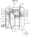
- the tip end portions 41c, 41d of the paired guide chips 41A, 41B are respectively inserted into the paired guide holes 42A, 42B as shown in FIGS. 9 and 10 .
- the guide chip 41B is inserted into the guide hole 42C in the guide mechanism 40C.
- a space exists in the height direction Y between each of the locking lug portions 33 and each of the locking holes 31 and each of the locking lug portions 33 is not locked to each of the locking holes 31 as shown in FIGS. 9 and 11 .
- the insertion of the paired guide chips 41A, 41B into the paired guide holes 42A, 42B is carried out before the locking of the locking lug portions 33 to the locking holes 31.
- the insertion in the one guide mechanism 40A and the insertion in the other guide mechanism 40B may be carried out simultaneously or the insertion in the other guide mechanism 40B may be carried out first and then the insertion in the one guide mechanism 40A may be carried out.
- An assembly method by which the worker carries out the insertion in the other guide mechanism 40B first in the paired guide mechanisms 40A, 40B will be described below.
- the protruding amount L2 from the inner face of the lid portion 21 on the side of the routing space 13 to the tip end portion 41c of the other guide chip 41B along the height direction Y is greater than the protruding amount L1 to the tip end portion 41d of the one guide chip 41A. Therefore, if the operator brings the lid member 20 close to the protector main body 10, the tip end portion 41d of the other guide chip 41B first comes in contact with the inner face 42h of the other guide hole 42B in the other guide mechanism 40B as shown in FIG. 8 . In this state, the worker turns the lid member 20 about the tip end portion 41d of the guide chip 41B (turns the lid member 20 in a direction of an arrow in FIG. 8 ).
- the tip end portion 41c of the guide chip 41A in the one guide mechanism 40A comes in contact with the inner face 42g of the one guide hole 42A.
- the width W1 along the width direction Z of the inclined inner face 42g of the one guide mechanism 40A shown in FIG. 7 is greater than the width W2 along the width direction Z of the inclined inner face 42h of the other guide mechanism 40B. Therefore, in the protector 1, even if the tip end portion 41d is slightly displaced from the inner face 42h during the turning of the lid member 20 about the tip end portion 41d of the other guide chip 41B, it is possible to insert the tip end portion 41c of the one guide chip 41A into the guide hole 42A as shown in FIG. 8 .
- the protector 1 in the embodiment it is possible to facilitate the insertion of the one guide chip 41A into the one guide hole 42A.
- the end portion 42i of the plate-shaped portion 42c of the one guide hole 42A on the side from which the guide chip 41A is inserted is disposed closer to the opening/closing opening 15 than the end portion 42j of the plate-shaped portion 42d of the other guide hole 42B on the side from which the guide chip 41B is inserted. Therefore, in the protector 1, it is possible to minimize a length of the turning of the lid member 20 in a circumferential direction about the tip end portion 41d of the other guide chip 41B in the other guide mechanism 40B. As a result, in the protector 1, it is possible to further facilitate the insertion of the one guide chip 41A into the one guide hole 42A.
- the worker further brings the lid portion 21 of the lid member 20 close to the base 11 of the protector main body 10.
- the locking lug portions 33 come close to the locking holes 31 from the other side in the height direction Y.
- the protruding chips 33a of the locking lug portions 33 shown in FIG. 11 come close to the side wall frame-shaped portions 31d of the locking holes 31 and the first rib portions 23a.
- the protruding chips 33a come in contact with the frame-shaped tapered portions 31i of the side wall frame-shaped portions 31d. Then, by the contact between the protruding chips 33a and the frame-shaped tapered portions 31i, the first opposed wall portions 12a, 12b are guided into between the paired first lid side wall portions 22a, 22b. Then, the protruding chip tapered portions 33e of the protruding chips 33a come in contact with the rib portions 23. As a result of the contact between the protruding chip tapered portions 33e and the rib portions 23, each of the protruding chips 33a is disposed between the rib portion 23 and the side wall frame-shaped portion 31d.
- the locking lug tapered portions 33f of the locking lugs 33b and the side wall frame-shaped portions 31d of the frame-shaped tapered portions 31i come in contact with each other.
- the paired first opposed wall portions 12a, 12b are elastically deformed such that the end portions 12e, 12f on the side of the opening/closing opening 15 come close to each other. Then, when the tip end portions 33d of the locking lugs 33b climb over the third portions 31g of the side wall frame-shaped portions 31d and the locking lug portions 33 and the locking holes 31 are locked to each other as shown in FIG.
- the paired first opposed wall portions 12a, 12b return into original states with the end portions 12e, 12f on the side of the opening/closing opening 15 moving away from each other and the lid member 20 is locked to the protector main body 10 in the correct position.
- the paired guide chips 41A, 41B are kept inserted into the paired guide holes 42A, 42B as shown in FIG. 12 .
- the lid member 20 When the lid member 20 is disposed in the correct position for closing the opening/closing opening 15 of the protector main body 10, the protruding chips 33a and the locking lugs 33b of the locking lug portions 33 are exposed from the locking holes 31 as shown in FIG. 13 . Therefore, the worker can easily know whether the lid member 20 is disposed in the correct position with respect to the protector main body 10 by visually recognizing whether the protruding chips 33a or the locking lug portions 33 exist in the locking holes 31 from the one side in the height direction Y.
- the guide mechanisms 40A, 40B, 40C can guide the lid member 20 to the correct position for closing the opening/closing opening 15 of the protector main body 10. Besides, in guiding the lid member 20 to the correct position, if the paired first opposed wall portions 12a, 12b are deformed, it is possible to lock the locking lug portions 33 to the locking holes 31 after correcting the deformation by use of the paired guide mechanisms 40A, 40B.
- the locking lug portions 33 are positioned at the end portions 12e, 12f of the first opposed wall portions 12a, 12b on the side of the opening/closing opening 15, it is possible to easily recognize the locking of the locking lug portions 33 to the locking holes 31 through the locking holes 31 from the one side in the height direction Y.
- the protector 1 having such a structure because the locking lug portions 33 in the locking mechanisms 30 are positioned at the end portions 12e, 12f of the first opposed wall portions 12a, 12b on the side of the opening/closing opening 15, it may be difficult to lock the locking lug portions to the locking holes when the paired first opposed wall portions 12a, 12b are deformed.
- the protruding amounts L1, L2 along the height direction Y of the paired guide chips 41A, 41B in the embodiment are set such that the insertion of the guide chips 41A, 41B into the guide holes 42A, 42B is carried out before the locking of the locking lug portions 33 to the locking holes 31. Therefore, in the protector 1 in the embodiment, it is possible to lock the locking lug portions 33 to the locking holes 31 after correcting shapes of the paired first opposed wall portions 12a, 12b by use of the paired guide mechanisms 40A, 40B.
- the protector 1 it is possible to easily recognize the locking of the locking lug portions 33 to the locking holes 31 and it is possible to easily lock the locking lug portions 33 to the locking holes 31 by use of the paired guide mechanisms 40A, 40B to properly carry out engagement even when the paired first opposed wall portions 12a, 12b are deformed.
- the paired guide mechanisms 40A, 40B it is possible to properly mount the lid member 20 to the protector main body 10.
- the protector main body 10 in which the first opposed wall portions 12a, 12b protruding in the height direction Y from the first base 11a are 20 cm or higher, the first opposed wall portions 12a, 12b may fall into or outward from the routing space 13 in the mounting of the lid member 20.
- the protector 1 in the embodiment even if the first opposed wall portions 12a, 12b are fallen into or outward from the routing space 13, it is possible to lock the locking lug portions 33 to the locking holes 31 after correcting the shapes of the paired first opposed wall portions 12a, 12b by use of the paired guide mechanisms 40A, 40B.
- the protector 1 and the wire harness WH1 have the following structure.
- the protector 1 and the like in the embodiment when the lid member 20 is disposed in the correct position for closing the opening/closing opening 15, the protruding chips 33a of the locking lug portions 33 are exposed from the lid through portions 31a in the lid portion 21 of the locking holes 31 as shown in FIG. 13 .
- the locking lugs 33b of the locking lug portions 33 are exposed from the side wall through portions 31b in the lid side wall portions 22 of the locking holes 31.
- the protector 1 and the wire harness WH1 have the following structure.
- the paired guide holes 42A, 42B in the embodiment are adjacent to the locking holes 31 in the axial direction X in the state in which the lid member 20 is disposed in the correct position for closing the opening/closing opening 15. Therefore, the paired guide mechanisms 40A, 40B can reliably guide the locking lug portions 33 to the locking holes 31.
- the protector 1 and the wire harness WH1 have the following structure.
- the paired guide holes 42A, 42B respectively include the plate-shaped portions 42c, 42d extending along the axial direction X, the support portions 42e, 42f that support the opposite end portions of the plate-shaped portions 42c, 42d, and the guide spaces 42s1, 42s2 which are positioned between the first opposed wall portions 12a, 12b and the plate-shaped portions 42c, 42d in the width direction Z and into which the guide chips 41A, 41B are inserted.
- the inner faces 42g, 42h of the plate-shaped portions 42c, 42d opposed to the first opposed wall portions 12a, 12b are inclined with respect to the height direction Y such that the guide spaces 42s1, 42s2 gradually widen from the side of the base 11 toward the side of the opening/closing opening 15.
- the width W1 along the width direction Z of the inclined inner face 42g of the one guide mechanism 40A is greater than the width W2 along the width direction Z of the inclined inner face 42g of the other guide mechanism 40B.
- the tip end portion 41c of the one guide chip 41A comes in contact with the inner face 42g of the guide hole 42A. Therefore, in the protector 1 in the embodiment, it is possible to facilitate the insertion of the one guide chip 41A into the one guide hole 42A.
- the protector 1 and the wire harness WH1 in the embodiment have the following structure.
- the end portion 42i of the plate-shaped portion 42d of the one guide hole 42A on the side from which the guide chip 41A is inserted is disposed closer to the opening/closing opening 15 than the end portion 42j of the plate-shaped portion 42c of the other guide hole 42B on the side from which the guide chip 41B is inserted. Therefore, in the protector 1, it is possible to minimize the length of the turning of the lid member 20 in the circumferential direction about the tip end portion 41d of the other guide chip 41B in the other guide mechanism 40B. As a result, it is possible to further facilitate the insertion of the one guide chip 41A into the one guide hole 42A.
- the protector 1 and the wire harness WH1 have the following structure.
- the protruding amounts L1, L2 (see FIG. 12 ) of the guide chips 41A, 41B along the height direction Y from the contact portions 21e, 21f of the lid member 20 that come in contact with the end portions 12e, 12f of the first opposed wall portions 12a, 12b on the side of the opening/closing opening 15 are greater than protruding amounts L3 (see FIGS. 3 and 6 ) of the locking lug portions 33 along the height direction Y from the end portions 12e, 12f of the first opposed wall portions 12a, 12b on the side of the opening/closing opening 15. Therefore, in the embodiment, it is possible to reliably carry out the insertion of the guide chips 41A, 41B into the guide holes 42A, 42B before the locking of the locking lug portions 33 to the locking holes 31.
- the protector 1 and the wire harness WH1 have the following structure.
- the locking lugs 33b are provided on outer face sides (opposite sides from the routing space 13) of the first opposed wall portions 12a, 12b. Therefore, in the protector 1, it is possible to suppress reduction of a volume of the routing space 13 by the locking lugs 33b.
- the protector 1 and the wire harness WH1 have the following structure.
- the paired guide mechanisms 40A, 40B are provided on the outer face sides (the opposite sides from the routing space 13) of the first opposed wall portions 12a, 12b. Therefore, in the protector 1, it is possible to suppress reduction of the volume of the routing space 13 by the paired guide mechanisms 40A, 40B.
- the protector 1 and the wire harness WH1 including the nine locking mechanisms 30 have been described in the above embodiment.
- the invention is not limited to these protector 1 and wire harness WH1 and the protector 1 and the wire harness WH1 need to have at least one locking mechanism 30, for example.
- the protector 1 and the wire harness WH1 including the protector main body 10 having the first opposed wall portions 12a, 12b and the second opposed wall portions 12c, 12d have been described in the above embodiment.
- the invention is not limited to these protector 1 and wire harness WH1 and the protector main body 10 needs to have at least the first opposed wall portions 12a, 12b.
- the protector 1 and the wire harness WH1 including the lid portion 21 having the first lid portion 21a and the second lid portion 21b and the lid side wall portions 22 having the first lid side wall portions 22a, 22b and the second lid side wall portions 22c, 22d have been described in the above embodiment.
- the invention is not limited to these protector 1 and wire harness WH1 and the lid portion 21 needs to have at least the first lid portion 21a and the first lid side wall portions 22a, 22b.
- the protruding amount L2 from the contact portion 21e to the tip end portion 41d of the other guide chip 41B is greater than the protruding amount L1 from the contact portion 21f to the tip end portion 41c of the one guide chip 41A.
- the invention is not limited to these protector 1 and wire harness WH1 and both of the protruding amounts L1, L2 may be the same.
- the protruding amount L2 from the contact portion 21e to the tip end portion 41d of the other guide chip 41B may be smaller than the protruding amount L1 from the contact portion 21f to the tip end portion 41c of the one guide chip 41A.
- a shape of the one guide mechanism 40A and a shape of the other guide mechanism 40B are different.
- the invention is not limited to these protector 1 and wire harness WH1 and the paired guide mechanisms 40A, 40B may have the same shapes.
- a position of the end portion 42i of the plate-shaped portion 42d of the one guide hole 42A and a position of the end portion 42j of the plate-shaped portion 42c of the other guide hole 42B are different in the height direction Y.
- the invention is not limited to these protector 1 and wire harness WH1 and the position of the end portion 42i of the plate-shaped portion 42d of the one guide hole 42A and the position of the end portion 42j of the plate-shaped portion 42c of the other guide hole 42B may be the same in the height direction Y.
- the locking lug portion is positioned at the end portion of the opposed wall portion on the side of the opening, it is possible to easily recognize the locking of the locking lug portion to the locking hole through the locking hole from one side in the protruding direction.
- the protruding amounts along the protruding direction of the paired guide chips are set such that the guide chips are inserted into the guide holes before the locking lug portion is locked to the locking hole. Therefore, in the protector, it is possible to lock the locking lug portion to the locking hole after correcting shapes of the paired opposed wall portions by use of the paired guide mechanisms, for example.
- the protector it is possible to easily recognize the locking of the locking lug portion to the locking hole and it is possible to easily lock the locking lug portion to the locking hole to properly carry out engagement.
- the lid member it is possible to properly mount the lid member to the protector main body.
Landscapes
- Engineering & Computer Science (AREA)
- Mechanical Engineering (AREA)
- Architecture (AREA)
- Civil Engineering (AREA)
- Structural Engineering (AREA)
- Details Of Indoor Wiring (AREA)
- Connection Of Plates (AREA)
Abstract
Description
- The present invention relates to a protector and a wire harness.
- As a conventional protector applied to a wire harness or the like for a vehicle, there is a protector disclosed in Japanese Patent Application Laid-open No.
2006-74843 - The protector described in above-mentioned Japanese Patent Application Laid-open No.
2006-74843 - The present invention has been made with the above circumstances in view and its object is to provide a protector and a wire harness that can be assembled properly.
- In order to achieve the above mentioned object, a protector according to one aspect of the present invention includes a protector main body including a base, paired opposed wall portions protruding from the base and opposed to each other along an opposed direction, a routing space that is formed by the base and the paired opposed wall portions and through which a wire is routed, and an opening that is formed by end portions of the paired opposed wall portions on an opposite side from the base and that opens on one side in a protruding direction of the opposed wall portions with respect to the base; a lid member that closes the opening; a locking mechanism including a locking hole that is formed in the lid member and opens on opposite sides in the protruding direction and a locking lug portion that is positioned at the end portion of the opposed wall portion on a side of the opening and that is locked to the locking hole, the locking mechanism locking the protector main body and the lid member to each other in a correct position where the lid member closes the opening; and paired guide mechanisms including paired guide chips respectively positioned at opposite end portions in the opposed direction of the lid member and extending along the protruding direction and paired guide holes that are respectively positioned at the end portions of the paired opposed wall portions on the side of the opening and into which the paired guide chips are respectively inserted along the protruding direction, wherein protruding amounts along the protruding direction of the paired guide chips are set such that the guide chips are inserted into the guide holes before the locking lug portion is locked to the locking hole.
- According to another aspect of the present invention, in the protector, it is preferable that each of the paired guide holes is adjacent to the locking hole in an adjacent direction intersecting the protruding direction and the opposed direction when the lid member is disposed in the correct position for closing the opening.
- According to still another aspect of the present invention, in the protector, it is preferable that each of the paired guide holes includes a plate-shaped portion extending along the adjacent direction intersecting the protruding direction and the opposed direction, a support portion that supports opposite end portions of the plate-shaped portion, and a guide space that is positioned between the opposed wall portion and the plate-shaped portion in the opposed direction and into which the guide chip is inserted, an inner face of the plate-shaped portion opposed to the opposed wall portion is inclined with respect to the protruding direction such that the guide space gradually widens from a side of the base toward the side of the opening, and a width along the opposed direction of the inclined inner face of one of the paired guide mechanisms is greater than a width along the opposed direction of the inclined inner face of the other guide mechanism in the paired guide mechanisms.
- In order to achieve the above mentioned object, a wire harness according to still another aspect of the present invention includes a wire having conductivity; and a protector that is mounted to the wire and protects the wire, wherein the protector includes a protector main body having a base, paired opposed wall portions protruding from the base and opposed to each other along an opposed direction, a routing space which is formed by the base and the paired opposed wall portions and through which the wire is routed, and an opening that is formed by end portions of the paired opposed wall portions on an opposite side from the base and that opens on one side in a protruding direction of the opposed wall portions with respect to the base, a lid member that closes the opening, a locking mechanism having a locking hole that is formed in the lid member and opens on opposite sides in the protruding direction and a locking lug portion that is positioned at the end portion of the opposed wall portion on a side of the opening and that is locked to the locking hole, the locking mechanism locking the protector main body and the lid member to each other in a correct position where the lid member closes the opening, and paired guide mechanisms having paired guide chips respectively positioned at opposite end portions in the opposed direction of the lid member and extending along the protruding direction and paired guide holes which are respectively positioned at the end portions of the paired opposed wall portions on the side of the opening and into which the paired guide chips are respectively inserted along the protruding direction, and protruding amounts along the protruding direction of the paired guide chips are set such that the guide chips are inserted into the guide holes before the locking lug portion is locked to the locking hole.
- The above and other objects, features, advantages and technical and industrial significance of this invention will be better understood by reading the following detailed description of presently preferred embodiments of the invention, when considered in connection with the accompanying drawings.
-
-
FIG. 1 is a perspective view of a protector according to an embodiment viewed from the front; -
FIG. 2 is a perspective view of the protector according to the embodiment viewed from behind; -
FIG. 3 is an exploded perspective view of the protector according to the embodiment; -
FIG. 4 is a perspective view of a lid member according to the embodiment viewed from the other side in a height direction; -
FIG. 5 is a perspective view of the lid member according to the embodiment from one side in the height direction; -
FIG. 6 is a perspective view of a pair of first opposed wall portions according to the embodiment viewed from the one side in the height direction; -
FIG. 7 is a sectional view of guide holes in a pair of guide mechanisms according to the embodiment; -
FIG. 8 is a sectional view of the pair of guide mechanisms and illustrating insertion of one of the guide mechanisms after insertion of the other of the guide mechanisms; -
FIG. 9 is a perspective view of the protector according to the embodiment with guide chips and the guide holes of the guide mechanisms locked to each other and locking holes and locking recognition chips of the locking mechanisms not locked to each other; -
FIG. 10 is a sectional view taken in a direction of arrows IX-IX inFIG. 9 ; -
FIG. 11 is a sectional view taken in a direction of arrows X-X inFIG. 9 ; -
FIG. 12 is a sectional view taken in a direction of arrows XII-XII inFIG. 1 ; and -
FIG. 13 is a sectional view taken in a direction of arrows XIII-XIII inFIG. 1 . - An embodiment according to the present invention will be described below in detail based on the drawings. The embodiment is not intended to limit the invention.
- Wires W are shown by two-dot chain lines in
FIGS. 1 and2 described below and are not shown in the other figures. In the following description, out of a first direction, a second direction, and a third direction intersecting each other, the first direction will be referred to as an "axial direction X", the second direction will be referred to as a "height direction Y", and the third direction will be referred to as a "width direction Z". Here, the axial direction X, the height direction Y, and the width direction Z are orthogonal to each other (intersecting each other). The height direction Y typically corresponds to a stacking direction in which a protectormain body 10 and alid member 20 are stacked, corresponds to a protruding direction in which opposedwall portions base 11, and corresponds to a protruding direction in which lidside wall portions 22 protrude with respect to alid portion 21. The width direction Z typically corresponds to an opposed direction in which the paired first opposed wall portions (paired opposed wall portions) 12a, 12b are opposed to each other and corresponds to an opposed direction in which paired first lidside wall portions holes 31 and guideholes opposed wall portions FIGS. 7 ,10 ,11 ,8 ,12 , and13 are sectional views in a plane including the height direction Y and the width direction Z (sectional views in a plane orthogonal to the axial direction X). The respective directions used in the following description are directions when respective portions of aprotector 1 are assembled unless otherwise specified. - The
protector 1 according to the present embodiment and shown inFIGS. 1 ,2 , and3 is mounted into a wire harness WH1 mounted to a vehicle such as an automobile and covers the wires W having conductivity to protect the wires W. For connection between respective devices mounted to the vehicle, for example, the wire harness WH1 is formed as a part assembly by binding the plurality of wires W used for power supply and signal communication such that the plurality of wires W are connected to the respective devices by use of connectors or the like. The wire harness WH1 includes the wires W having the conductivity and theprotector 1 that is mounted to the wires W to protect the wires W. The wires W are formed by metal rods, electric wires, electric wire bundles, or the like, for example. - The metal rods are rod-shaped members that have conductivity and are covered with sheaths, having insulation properties, from outside. The electric wires are conductors (cable cores) formed by a plurality of metal wires that have conductivity and are covered with sheaths, having insulation properties, from outside. The electric wire bundles are the electric wires that are bundled. The wire harness WH1 in the embodiment achieves a structure capable of properly assembling the
protector 1 that is mounted to the wires W, by providinglocking mechanisms 30 and pairedguide mechanisms protector 1. A structure of theprotector 1 will be described below in detail with reference to the respective figures. The wire harness WH1 may also include an electric connection box, grommets, fixtures, connectors, and the like. - The
protector 1 is made of resin material having an insulation property and formed in a substantially tubular shape. In theprotector 1 according to the embodiment, the wires W are routed while bent in a substantially L shape. However, the wires W are not necessarily routed in this manner and may be routed straight. Theprotector 1 includes the protectormain body 10, thelid member 20, thelocking mechanisms 30, the pair ofguide mechanisms cover 50. In theprotector 1, the protectormain body 10 and thelid member 20 are formed separately and mounted to each other by use of thelocking mechanisms 30. Theprotector 1 is formed into the substantially L-shaped tubular shape as a whole by mounting of the protectormain body 10 and thelid member 20 to each other. In the above-described structure, theprotector 1 in the embodiment achieves the structure capable of properly mounting thelid member 20 to the protectormain body 10 by use of the pair ofguide mechanisms protector 1 further includes aguide mechanism 40C provided separately from the pair ofguide mechanisms protector 1 will be described below in detail with reference to the respective figures. - Through the protector
main body 10, the wires W are inserted and routed. Here, the protectormain body 10 is formed in a gutter shape open at one end portion in the axial direction X, opposite end portions in the width direction Z, and one end portion in the height direction Y. Through the protectormain body 10, the wires W are inserted along the axial direction X and the width direction Z. - More specifically, the protector
main body 10 has thebase 11 and main bodyside wall portions 12. The protectormain body 10 is formed to include thebase 11, arouting space 13 formed by the main bodyside wall portions 12,insertion openings 14, and an opening/closingopening 15. The protectormain body 10 is formed in the shape of the substantially L-shaped tub as described above with thebase 11 and the main bodyside wall portions 12 integrated with each other. - The
base 11 is a bottom body for defining therouting space 13 as an inner space of the protectormain body 10. Thebase 11 is formed in a substantially plate shape with a plate thickness direction oriented in the height direction Y. Thebase 11 has a first base (base) 11a extending in the axial direction X and asecond base 11b extending in the width direction Z. Thefirst base 11a has a predetermined width in the width direction Z for routing of the wires W. Thesecond base 11b has a predetermined width in the axial direction X for routing of the wires W. Thebase 11 is formed in a substantially L shape with thefirst base 11a and thesecond base 11b formed integrally. - The main body
side wall portions 12 are wall bodies for defining therouting space 13 as the inner space of the protectormain body 10. The main bodyside wall portions 12 include the paired first opposedwall portions wall portions opposed wall portions base 11. - Both of the paired first opposed
wall portions opposed wall portions wall portions first base 11a in the width direction Z and positioned at an interval and opposed to each other along the width direction Z. Here, the paired first opposedwall portions first base 11a and extend from one end portion to the other end portion of thefirst base 11a along the axial direction X. In other words, thefirst base 11a is positioned between the paired first opposedwall portions first base 11a are connected to the firstopposed wall portions wall portions first base 11a. In the paired first opposedwall portions opposed wall portion 12a and the other firstopposed wall portion 12b have substantially equal lengths along the height direction Y and the other firstopposed wall portion 12b has a greater length along the axial direction X than the one firstopposed wall portion 12a. - Both of the paired second opposed
wall portions opposed wall portions wall portions second base 11b in the axial direction X and positioned at an interval and opposed to each other along the axial direction X. Here, the paired second opposedwall portions second base 11b and extend from one end portion to the other end portion of thesecond base 11b along the width direction Z. In other words, thesecond base 11b is positioned between the paired second opposedwall portions second base 11b are connected to the secondopposed wall portions wall portions second base 11b. In the paired second opposedwall portions opposed wall portion 12c and the other secondopposed wall portion 12d have substantially equal lengths along the height direction Y and the other secondopposed wall portion 12d has a greater length along the width direction Z than the one secondopposed wall portion 12c. - In the protector
main body 10 formed as described above, therouting space 13, the plurality ofinsertion openings 14, and the opening/closingopening 15 are formed by thebase 11 and the main bodyside wall portions 12. Therouting space 13 is a space through which the wires W are routed along the axial direction X and the width direction Z. Therouting space 13 is formed as the inner space surrounded with thebase 11 and the main bodyside wall portions 12. Theinsertion openings 14 are openings through which the wires W are inserted into therouting space 13. Theinsertion openings 14 include afirst insertion opening 14a formed at one end portion in the axial direction X by the paired first opposedwall portions first base 11a. Thefirst insertion opening 14a opens along the width direction Z and the height direction Y as shown inFIG. 1 . Theinsertion openings 14 include a second insertion opening 14b and athird insertion opening 14c formed at opposite end portions in the width direction Z by the paired second opposedwall portions second base 11b. Thesecond insertion opening 14b is positioned at the one end portion in the width direction Z and opens along the axial direction X and the height direction Y. Thethird insertion opening 14c is positioned at the other end portion in the width direction Z and opens along the axial direction X and the height direction Y (seeFIG. 2 ). As shown inFIG. 3 , the opening/closingopening 15 is an opening that opens therouting space 13 to an outside and is the opening that is closed with thelid member 20. The opening/closingopening 15 is opened when the wires W are inserted through therouting space 13 and is closed with thelid member 20 after the wires W are inserted through therouting space 13, for example. The opening/closingopening 15 is formed by end portions of the respectiveopposed wall portions base 11. The opening/closingopening 15 is open on one side along the height direction Y of the respectiveopposed wall portions base 11. - The
lid member 20 is mounted to the protectormain body 10 to close (block) the opening/closingopening 15 formed in the protectormain body 10. Thelid member 20 has alid portion 21 and lidside wall portions 22 as shown inFIGS. 1 ,2 ,3 , and4 . Thelid member 20 is formed in a shape of a substantially L-shaped plate corresponding to a shape of the protectormain body 10 by thelid portion 21 and the lidside wall portions 22 integrated with each other. - The
lid portion 21 is a lid body that closes the opening/closingopening 15 of the protectormain body 10 and defines therouting space 13. Thelid portion 21 is formed in a substantially plate shape with a plate thickness direction oriented in the height direction Y. Thelid portion 21 has afirst lid portion 21a opposed to thefirst base 11a in the height direction Y and extending in the axial direction X and asecond lid portion 21b opposed to thesecond base 11b in the height direction Y and extending in the width direction Z. Thefirst lid portion 21a has a predetermined width in the width direction Z so as to be able to close therouting space 13. Thesecond lid portion 21b has a predetermined width in the axial direction X so as to be able to close therouting space 13. Thelid portion 21 is formed in a substantially L shape with thefirst lid portion 21a and thesecond lid portion 21b formed integrally. - The lid
side wall portions 22 are overlapping bodies that overlap the main bodyside wall portions 12 of the protectormain body 10 and include paired first lidside wall portions - The paired first lid
side wall portions first lid portion 21a. Here, both of the first lidside wall portions side wall portions side wall portions first lid portion 21a in the width direction Z and positioned at an interval and opposed to each other along the width direction Z. Here, the paired first lidside wall portions first lid portion 21a and extend from one end portion to the other end portion of thefirst lid portion 21a along the axial direction X. In other words, thefirst lid portion 21a is positioned between the paired first lidside wall portions first lid portion 21a are connected to the first lidside wall portions side wall portions first lid portion 21a. The first lidside wall portions main body 10 along the height direction Y from thefirst lid portion 21a. In the pair of first lidside wall portions side wall portion 22a and the other first lidside wall portion 22b have substantially equal lengths along the height direction Y and the other first lidside wall portion 22b has a greater length along the axial direction X than the one second lidside wall portion 22c. - The paired second lid
side wall portions second lid portion 21b. Here, both of the second lidside wall portions side wall portions side wall portions second lid portion 21b in the axial direction X and positioned at an interval and opposed to each other along the axial direction X. Here, the paired second lidside wall portions second lid portion 21b and extend from one end portion to the other end portion of thesecond lid portion 21b along the width direction Z. In other words, thesecond lid portion 21b is positioned between the paired second lidside wall portions second lid portion 21b are connected to the second lidside wall portions side wall portions second lid portion 21b. The second lidside wall portions main body 10 along the height direction Y from thesecond lid portion 21b. In the pair of second lidside wall portions side wall portion 22c and the other second lidside wall portion 22d have substantially equal lengths along the height direction Y and the other second lidside wall portion 22d has a greater length along the width direction Z than the one second lidside wall portion 22c. - As shown in
FIG. 4 ,rib portions 23 are formed on thelid member 20. More specifically,first rib portions 23a are formed on thefirst lid portion 21a of thelid member 20 andsecond rib portions 23b are formed on thesecond lid portion 21b of thelid member 20. Thefirst rib portions 23a are formed in rectangular plate shapes to be opposed, in the width direction Z, to side wall frame-shapedportions 31d and side wall throughportions 31b formed by the side wall frame-shapedportions 31d (described later). Thefirst rib portions 23a are disposed on a side of therouting space 13 between the paired first lidside wall portions second rib portions 23b are formed in rectangular plate shapes to be opposed, in the axial direction X, to the side wall frame-shapedportions 31d and the side wall throughportions 31b formed by the side wall frame-shapedportions 31d. Thesecond rib portions 23b are disposed on the side of therouting space 13 between the paired second lidside wall portions - As shown in
FIGS. 1 ,2 ,12 , and13 , the lockingmechanisms 30 are mechanisms that lock the protectormain body 10 and thelid member 20 to each other in a correct position where thelid member 20 closes (blocks) the opening/closingopening 15. Here, the correct position is such a position that thelid portion 21 of thelid member 20 closes the opening/closingopening 15 of the protectormain body 10 and the main bodyside wall portions 12 and the lidside wall portions 22 are opposed to and overlap each other. When theprotector 1 is in a closed state in which thelid member 20 is disposed in the correct position, theend portions wall portions opening 15 andcontact portions lid portion 21 positioned on the side of therouting space 13 come in contact with each other as shown inFIG. 12 . When thelid member 20 is disposed in the correct position, the lidside wall portions 22 are positioned outside the main bodyside wall portions 12, i.e., positioned to be opposed to the main bodyside wall portions 12 on opposite sides from therouting space 13. More specifically, in the closed state, the first lidside wall portions opposed wall portions opposed wall portions side wall portions opposed wall portions opposed wall portions - The
protector 1 in the embodiment has the nine lockingmechanisms 30. Each of the lockingmechanisms 30 has the same structure and includes the lockinghole 31 and a lockinglug portion 33. For convenience of explanation, in the present description, the locking holes 31 provided to thefirst lid portion 21a and the first lidside wall portions second lid portion 21b and the second lidside wall portions lug portions 33 provided to the firstopposed wall portions lug portions 33 provided to the secondopposed wall portions - Each of the locking holes 31 is locked to each of the locking
lug portions 33 in the closed state in which the protectormain body 10 and thelid member 20 are in the correct position. Each of the locking holes 31 is formed in thelid member 20 to open on opposite sides in the height direction Y. The plurality of lockingholes 31, the number of which corresponds to the number of the lockinglug portions 33, are provided. Each of the locking holes 31 is formed at a position opposed to the lockinglug portion 33 along the height direction Y. - Each of the locking holes 31 is a through hole formed by a portion forming a part of the
lid member 20 to extend astride thelid portion 21 and the lidside wall portion 22 as shown inFIGS. 4 and5 . Each of the locking holes 31 passes through thelid portion 21 and the lidside wall portion 22. In other words, each of the locking holes 31 is provided at an edge portion formed by intersection of thelid portion 21 and the lidside wall portion 22, passes through thelid portion 21 along the height direction Y, and passes through the lidside wall portion 22 along the width direction Z. Each of the locking holes 31 in the embodiment includes a lid throughportion 31a and the side wall throughportion 31b. - The lid through
portion 31a is a portion of the lockinghole 31 passing through thelid portion 21 along the height direction Y and is formed by a lid frame-shapedportion 31c forming a part of thefirst lid portion 21a. The lid frame-shapedportion 31c is formed into a C shape by afirst portion 31e extending along the axial direction X andsecond portions 31f positioned at opposite end portions of thefirst portion 31e. - The side wall through
portion 31b is a portion of the lockinghole 31 passing through the lidside wall portion 22 along the width direction Z and is formed by the side wall frame-shapedportion 31d forming a part of the first lidside wall portion 22a. The side wall frame-shapedportion 31d is formed into a C shape by athird portion 31g extending along the axial direction X andfourth portions 31h supporting opposite end portions of thethird portion 31g. - As shown in
FIGS. 4 and11 , thethird portions 31g of the side wall frame-shapedportions 31d of the paired lockingmechanisms 30 opposed to each other have frame-shapedtapered portions 31i on tip end sides (on farther sides from the lid portion 21) of inner faces opposed to each other. Each of the frame-shapedtapered portions 31i is formed by a flat face inclined with respect to the height direction Y and the width direction Z. Each of thethird portions 31g is formed to have a smaller thickness in the width direction Z on the farther side from thelid portion 21 than on a closer side to thelid portion 21 due to the frame-shapedtapered portion 31i. - As shown in
FIG. 6 , the respectivelocking lug portions 33 are positioned atend portions opposed wall portions opening 15. Each of the lockinglug portions 33 is locked to each of the locking holes 31 in the closed state in which the protectormain body 10 and thelid member 20 are in the correct position. Each of the lockinglug portions 33 is formed at a position opposed to the lockinghole 31 along the height direction Y. Each of the lockinglug portions 33 has aprotruding chip 33a and a lockinglug 33b. - The respective
protruding chips 33a are formed to protrude in rectangular plate shapes in the height direction Y from theend portions opposed wall portions opening 15. - The protruding
chips 33a of the paired lockingmechanisms 30 have protruding chip taperedportions 33e on opposed faces opposed to each other. Each of the protruding chip taperedportions 33e is formed by a flat face inclined with respect to the height direction Y and the width direction Z. The protrudingchips 33a are formed to have smaller thicknesses in the width direction Z on farther sides from theend portions opposed wall portions end portions portions 33e. - The locking lugs 33b are provided on outer face sides (opposite sides from the routing space 13) of the first
opposed wall portions opposed wall portions locking lug portions 33 are formed to protrude outward from the firstopposed wall portions lug portions 33 has abase end portion 33c, atip end portion 33d, and a locking lug taperedportion 33f. Thebase end portions 33c are positioned on the sides of the firstopposed wall portions tip end portion 33d protrudes toward an opposite side (a farther side from the routing space 13) in the width direction Z from thebase end portion 33c. The locking lug taperedportion 33f is positioned on a closer side to the opening/closingopening 15 between thebase end portion 33c and thetip end portion 33d. The locking lug taperedportion 33f is formed by a flat face inclined with respect to the height direction Y and the width direction Z. The locking lugs 33b are formed to have smaller thicknesses in the width direction Z on closer sides to theend portions opposed wall portions opening 15 than on farther sides from theend portions portions 33f. - In the correct position where the
lid portion 21 closes the opening/closingopening 15, in each of the lockingmechanisms 30 formed as described above, the lockinglug portion 33 is locked to the lockinghole 31 by insertion of the protrudingchip 33a into the lid throughportion 31a and insertion of the lockinglug 33b into the side wall throughportion 31b. Therefore, in theprotector 1, the protectormain body 10 and thelid member 20 can be locked to each other in the correct position by use of the lockingmechanisms 30. - The paired
guide mechanisms lid member 20 toward the correct position of the protectormain body 10 and guide the lockinglug portions 33 toward the locking holes s31. The pairedguide mechanisms opposed wall portions guide chips guide holes - As shown in
FIGS. 4 and10 , therespective guide chips lid member 20, and extending along the height direction Y. More specifically, therespective guide chips lug portions 33 are locked to the locking holes 31. Here, both of therespective guide chips lugs 33b unlike the lockinglug portions 33. To put it more concretely, respective faces of therespective guide chips tip end portions - The guide chips 41A, 41B have guide tapered
portions tip end portions portions guide chips tip end portions guide chips lid portion 21 than on a closer side to thelid portion 21 due to the guide taperedportions tip end portions guide chips - Out of protruding amounts L1, L2 of the paired
guide chips lid portion 21 on the side of therouting space 13 shown inFIG. 12 , the protruding amount L2 of theother guide chip 41B to thetip end portion 41d is greater than the protruding amount L1 of the oneguide chip 41A to thetip end portion 41c. In the closed state of theprotector 1, theend portions opposed wall portions opening 15 are in contact with thecontact portions lid portion 21 on the side of therouting space 13. The protruding amounts L1, L2 of theguide chips contact portions FIG. 6 ) of the lockinglug portions 33 along the height direction Y from theend portions opposed wall portions opening 15. Therefore, in assembly (described later) of theprotector 1, the insertion of theguide chips lug portions 33 to the locking holes 31. - As shown in
FIGS. 1 ,2 , and3 , the pairedguide holes end portions wall portions opening 15, into which the pairedguide chips guide holes lug portions 33 in the axial direction X. Therespective guide holes guide chips - As shown in
FIG. 2 , the oneguide hole 42A includes a plate-shapedportion 42c, pairedsupport portions 42e, and a guide space 42s1 (seeFIG. 7 ). The plate-shapedportion 42c extends along the axial direction X. The pairedsupport portions 42e support opposite end portions in the axial direction X of the plate-shapedportion 42c. As shown inFIG. 7 , the guide space 42s1 is positioned between the firstopposed wall portion 12b and the plate-shapedportion 42c in the width direction Z and theguide chip 41A is inserted into the guide space 42s1. Aninner face 42g of the plate-shapedportion 42c opposed to the firstopposed wall portion 12b is inclined with respect to the height direction Y and the width direction Z such that the guide space 42s1 gradually widens from a side of thefirst base 11a toward a side of the opening/closingopening 15. In other words, because the plate-shapedportion 42c is inclined with respect to the height direction Y and the width direction Z, the guide space 42s1 has a larger opening on the side of the opening/closingopening 15 than on the side of thefirst base 11a in the width direction Z. - As shown in
FIG. 3 , theother guide hole 42B includes a plate-shapedportion 42d, pairedsupport portions 42f, and a guide space 42s2 (seeFIG. 7 ). The plate-shapedportion 42d extends along the axial direction X. The pairedsupport portions 42f support opposite end portions in the axial direction X of the plate-shapedportion 42d. As shown inFIG. 7 , the guide space 42s2 is positioned between the firstopposed wall portion 12a and the plate-shapedportion 42d in the width direction Z and theguide chip 41B is inserted into the guide space 42s2. Aninner face 42h of the plate-shapedportion 42d opposed to the firstopposed wall portion 12a is inclined with respect to the height direction Y and the width direction Z such that the guide space 42s2 gradually widens from a side of thefirst base 11a toward a side of the opening/closingopening 15. In other words, because the plate-shapedportion 42d is inclined with respect to the height direction Y and the width direction Z, the guide space 42s2 has a larger opening on the side of the opening/closingopening 15 than on the side of thefirst base 11a in the width direction Z. - In the paired
guide mechanisms inner face 42g of the oneguide mechanism 40A is greater than a width w2 along the width direction Z of the inclinedinner face 42h of theother guide mechanism 40B. Anend portion 42i of the plate-shapedportion 42d of the oneguide hole 42A on a side from which theguide chip 41A is inserted is disposed closer to the opening/closingopening 15 than anend portion 42j of the plate-shapedportion 42c of theother guide hole 42B on a side from which theguide chip 41B is inserted. - As shown in
FIGS. 6 and7 , theend portion 12f, on the side of the opening/closingopening 15, of the firstopposed wall portion 12b on which the oneguide hole 42A is disposed is provided with an opposed wall taperedportion 12g. The opposed wall taperedportion 12g is positioned on the outer face positioned on an opposite side from inner faces of the paired first opposedwall portions opposed wall portion 12b is formed to have a smaller thickness in the width direction Z on a farther side from thefirst base 11a than on a closer side to thefirst base 11a due to the opposed wall taperedportion 12g. - The
end portion 12e, on the side of the opening/closingopening 15, of the firstopposed wall portion 12a on which theother guide hole 42B is disposed is provided with an opposed wall taperedportion 12h. The opposed wall taperedportion 12h is positioned on the outer face positioned on an opposite side from the inner faces of the paired first opposedwall portions opposed wall portion 12a is formed to have a smaller thickness in the width direction Z on a farther side from thefirst base 11a than on a closer side to thefirst base 11a due to the opposed wall taperedportion 12h. - As shown in
FIGS. 1 and2 , the pairedguide holes lid member 20 is disposed in the correct position for closing the opening/closingopening 15. More specifically, the pairedguide holes portions 31d of the locking holes 31 and thesupport portions - Here, the
protector 1 further includes theguide mechanism 40C provided separately from theguide mechanisms guide mechanism 40C has the same structure as theguide mechanism 40B but is disposed differently with respect to theprotector 1. To put it more concretely, theguide mechanism 40C has aguide chip 41C provided to the second lidside wall portion 22d and extending along the height direction Y and aguide hole 42C provided at an end portion of the secondopposed wall portion 12d on the side of the opening/closingopening 15 as shown inFIG. 2 . Because a structure of theguide chip 41C is the same as a structure of theguide chip 41B and a structure of theguide hole 42C is the same as a structure of theguide hole 42B, the structures of theguide chip 41C and theguide hole 42C will not be described. - The
cover 50 shown inFIG. 3 restricts lifting of the wires W from therouting space 13 after the wires W are routed through therouting space 13 and before thelid member 20 is disposed in the correct position of the protectormain body 10. Thecover 50 is made of resin material having an insulation property and formed in a plate shape extending in the axial direction X and the width direction Z. Thecover 50 is mounted to the secondopposed wall portion 12c by ahinge 51 and integrally supported on the protectormain body 10. - In the
protector 1 formed as described above, thelid member 20 is mounted to the protectormain body 10 and thelid member 20 is properly mounted to the protectormain body 10 as shown inFIGS. 3 ,9 ,10 ,11 ,12 , and13 . - First, a worker turns the
cover 50 about thehinge 51 with respect to the protectormain body 10 shown inFIG. 3 and then, disposes the wires W in therouting space 13 of the protectormain body 10. Next, the worker turns thecover 50 about thehinge 51 to thereby restrict the lifting of the wires W from therouting space 13 with thecover 50. - Then, while leaving a space between the base 11 of the protector
main body 10 and thelid portion 21 of thelid member 20, the worker opposes thefirst base 11a and thefirst lid portion 21a to each other and opposes thesecond base 11b and thesecond lid portion 21b to each other in the height direction Y. Then, the worker brings thelid portion 21 of thelid member 20 close to thebase 11 of the protectormain body 10 in the height direction Y. - When the
lid member 20 comes close to the protectormain body 10, thetip end portions guide chips end portions wall portions lid member 20 is brought close to the protectormain body 10 when thelid member 20 is displaced in the width direction Z from the correct position with respect to the protectormain body 10 on one side in the height direction Y of the correct position, for example, the guide taperedportions FIG. 8 come in contact with the opposed wall taperedportions portions portions guide chips opposed wall portions lid member 20 is brought close to the protectormain body 10 when thelid member 20 is aligned with the correct position with respect to the protectormain body 10 on the one side in the height direction Y of the correct position, the guide taperedportions portions - As described above, the inner faces 42g, 42h of the plate-shaped
portions guide holes lid member 20 is brought close to the protectormain body 10 when thelid member 20 is displaced in the width direction Z from the correct position with respect to the protectormain body 10 on the one side in the height direction Y of the correct position, the guide taperedportions inner faces portions inner faces tip end portions guide chips guide holes lid member 20 is brought close to the protectormain body 10 when thelid member 20 is aligned with the correct position with respect to the protectormain body 10 on the one side in the height direction Y of the correct position, the guide taperedportions inner faces - As described above, if the worker brings the
lid member 20 close to the protectormain body 10, thetip end portions guide chips guide holes FIGS. 9 and10 . If the worker inserts theguide chip 41B into theguide hole 42B in theguide mechanism 40B, theguide chip 41C is inserted into theguide hole 42C in theguide mechanism 40C. In this state, however, a space exists in the height direction Y between each of the lockinglug portions 33 and each of the locking holes 31 and each of the lockinglug portions 33 is not locked to each of the locking holes 31 as shown inFIGS. 9 and11 . In other words, in theprotector 1, the insertion of the pairedguide chips guide holes guide mechanisms lug portions 33 to the locking holes 31. - In the
protector 1 in the embodiment, the insertion in the oneguide mechanism 40A and the insertion in theother guide mechanism 40B may be carried out simultaneously or the insertion in theother guide mechanism 40B may be carried out first and then the insertion in the oneguide mechanism 40A may be carried out. An assembly method by which the worker carries out the insertion in theother guide mechanism 40B first in the pairedguide mechanisms - In the
protector 1, as shown inFIG. 12 , the protruding amount L2 from the inner face of thelid portion 21 on the side of therouting space 13 to thetip end portion 41c of theother guide chip 41B along the height direction Y is greater than the protruding amount L1 to thetip end portion 41d of the oneguide chip 41A. Therefore, if the operator brings thelid member 20 close to the protectormain body 10, thetip end portion 41d of theother guide chip 41B first comes in contact with theinner face 42h of theother guide hole 42B in theother guide mechanism 40B as shown inFIG. 8 . In this state, the worker turns thelid member 20 about thetip end portion 41d of theguide chip 41B (turns thelid member 20 in a direction of an arrow inFIG. 8 ). Then, in theprotector 1, thetip end portion 41c of theguide chip 41A in the oneguide mechanism 40A comes in contact with theinner face 42g of the oneguide hole 42A. In theprotector 1, in the above-described operation, the width W1 along the width direction Z of the inclinedinner face 42g of the oneguide mechanism 40A shown inFIG. 7 is greater than the width W2 along the width direction Z of the inclinedinner face 42h of theother guide mechanism 40B. Therefore, in theprotector 1, even if thetip end portion 41d is slightly displaced from theinner face 42h during the turning of thelid member 20 about thetip end portion 41d of theother guide chip 41B, it is possible to insert thetip end portion 41c of the oneguide chip 41A into theguide hole 42A as shown inFIG. 8 . Therefore, in theprotector 1 in the embodiment, it is possible to facilitate the insertion of the oneguide chip 41A into the oneguide hole 42A. In theprotector 1, theend portion 42i of the plate-shapedportion 42c of the oneguide hole 42A on the side from which theguide chip 41A is inserted is disposed closer to the opening/closingopening 15 than theend portion 42j of the plate-shapedportion 42d of theother guide hole 42B on the side from which theguide chip 41B is inserted. Therefore, in theprotector 1, it is possible to minimize a length of the turning of thelid member 20 in a circumferential direction about thetip end portion 41d of theother guide chip 41B in theother guide mechanism 40B. As a result, in theprotector 1, it is possible to further facilitate the insertion of the oneguide chip 41A into the oneguide hole 42A. - Then, the worker further brings the
lid portion 21 of thelid member 20 close to thebase 11 of the protectormain body 10. When thelid member 20 comes close to the protectormain body 10, the lockinglug portions 33 come close to the locking holes 31 from the other side in the height direction Y. To put it concretely, the protrudingchips 33a of the lockinglug portions 33 shown inFIG. 11 come close to the side wall frame-shapedportions 31d of the locking holes 31 and thefirst rib portions 23a. If thelid member 20 is brought close to the protectormain body 10 when thelid member 20 is displaced in the width direction Z from the correct position with respect to the protectormain body 10 on the one side in the height direction Y of the correct position, the protrudingchips 33a come in contact with the frame-shapedtapered portions 31i of the side wall frame-shapedportions 31d. Then, by the contact between the protrudingchips 33a and the frame-shapedtapered portions 31i, the firstopposed wall portions side wall portions portions 33e of the protrudingchips 33a come in contact with therib portions 23. As a result of the contact between the protruding chip taperedportions 33e and therib portions 23, each of the protrudingchips 33a is disposed between therib portion 23 and the side wall frame-shapedportion 31d. - When the
lid member 20 further comes close to the protectormain body 10, the locking lug taperedportions 33f of the locking lugs 33b and the side wall frame-shapedportions 31d of the frame-shapedtapered portions 31i come in contact with each other. When the locking lug taperedportions 33f and the side wall frame-shapedportions 31d come in contact with each other, the paired first opposedwall portions end portions opening 15 come close to each other. Then, when thetip end portions 33d of the locking lugs 33b climb over thethird portions 31g of the side wall frame-shapedportions 31d and the lockinglug portions 33 and the locking holes 31 are locked to each other as shown inFIG. 13 , the paired first opposedwall portions end portions opening 15 moving away from each other and thelid member 20 is locked to the protectormain body 10 in the correct position. In this state, in theprotector 1, the pairedguide chips guide holes FIG. 12 . - When the
lid member 20 is disposed in the correct position for closing the opening/closingopening 15 of the protectormain body 10, the protrudingchips 33a and the locking lugs 33b of the lockinglug portions 33 are exposed from the locking holes 31 as shown inFIG. 13 . Therefore, the worker can easily know whether thelid member 20 is disposed in the correct position with respect to the protectormain body 10 by visually recognizing whether the protrudingchips 33a or the lockinglug portions 33 exist in the locking holes 31 from the one side in the height direction Y. - In the
protector 1, theguide mechanisms lid member 20 to the correct position for closing the opening/closingopening 15 of the protectormain body 10. Besides, in guiding thelid member 20 to the correct position, if the paired first opposedwall portions lug portions 33 to the locking holes 31 after correcting the deformation by use of the pairedguide mechanisms - In the
protector 1 and the wire harness WH1 described above, because the lockinglug portions 33 are positioned at theend portions opposed wall portions opening 15, it is possible to easily recognize the locking of the lockinglug portions 33 to the locking holes 31 through the locking holes 31 from the one side in the height direction Y. In theprotector 1 having such a structure, because the lockinglug portions 33 in the lockingmechanisms 30 are positioned at theend portions opposed wall portions opening 15, it may be difficult to lock the locking lug portions to the locking holes when the paired first opposedwall portions guide chips guide chips lug portions 33 to the locking holes 31. Therefore, in theprotector 1 in the embodiment, it is possible to lock the lockinglug portions 33 to the locking holes 31 after correcting shapes of the paired first opposedwall portions guide mechanisms protector 1, it is possible to easily recognize the locking of the lockinglug portions 33 to the locking holes 31 and it is possible to easily lock the lockinglug portions 33 to the locking holes 31 by use of the pairedguide mechanisms wall portions lid member 20 to the protectormain body 10. Especially in a case of the protectormain body 10 in which the firstopposed wall portions first base 11a are 20 cm or higher, the firstopposed wall portions routing space 13 in the mounting of thelid member 20. However, in theprotector 1 in the embodiment, even if the firstopposed wall portions routing space 13, it is possible to lock the lockinglug portions 33 to the locking holes 31 after correcting the shapes of the paired first opposedwall portions guide mechanisms - The
protector 1 and the wire harness WH1 have the following structure. In theprotector 1 and the like in the embodiment, when thelid member 20 is disposed in the correct position for closing the opening/closingopening 15, the protrudingchips 33a of the lockinglug portions 33 are exposed from the lid throughportions 31a in thelid portion 21 of the locking holes 31 as shown inFIG. 13 . Moreover, the locking lugs 33b of the lockinglug portions 33 are exposed from the side wall throughportions 31b in the lidside wall portions 22 of the locking holes 31. Thus, in theprotector 1, it is possible to further facilitate the recognition of the locking of the lockinglug portions 33 to the locking holes 31. - Furthermore, the
protector 1 and the wire harness WH1 have the following structure. The pairedguide holes lid member 20 is disposed in the correct position for closing the opening/closingopening 15. Therefore, the pairedguide mechanisms lug portions 33 to the locking holes 31. As a result, in the embodiment, it is possible to more easily lock the lockinglug portions 33 to the locking holes 31 by use of the pairedguide mechanisms wall portions lid member 20 to the protectormain body 10. - The
protector 1 and the wire harness WH1 have the following structure. The pairedguide holes portions support portions portions opposed wall portions portions guide chips portions opposed wall portions opening 15. The width W1 along the width direction Z of the inclinedinner face 42g of the oneguide mechanism 40A is greater than the width W2 along the width direction Z of the inclinedinner face 42g of theother guide mechanism 40B. Therefore, if thelid member 20 is turned about thetip end portion 41d of theguide chip 41B with theother guide chip 41B inserted into theguide hole 42B in theother guide mechanism 40B, thetip end portion 41c of the oneguide chip 41A comes in contact with theinner face 42g of theguide hole 42A. Therefore, in theprotector 1 in the embodiment, it is possible to facilitate the insertion of the oneguide chip 41A into the oneguide hole 42A. - Moreover, the
protector 1 and the wire harness WH1 in the embodiment have the following structure. Theend portion 42i of the plate-shapedportion 42d of the oneguide hole 42A on the side from which theguide chip 41A is inserted is disposed closer to the opening/closingopening 15 than theend portion 42j of the plate-shapedportion 42c of theother guide hole 42B on the side from which theguide chip 41B is inserted. Therefore, in theprotector 1, it is possible to minimize the length of the turning of thelid member 20 in the circumferential direction about thetip end portion 41d of theother guide chip 41B in theother guide mechanism 40B. As a result, it is possible to further facilitate the insertion of the oneguide chip 41A into the oneguide hole 42A. - In addition, the
protector 1 and the wire harness WH1 have the following structure. In the above-described closed state, the protruding amounts L1, L2 (seeFIG. 12 ) of theguide chips contact portions lid member 20 that come in contact with theend portions opposed wall portions opening 15 are greater than protruding amounts L3 (seeFIGS. 3 and6 ) of the lockinglug portions 33 along the height direction Y from theend portions opposed wall portions opening 15. Therefore, in the embodiment, it is possible to reliably carry out the insertion of theguide chips lug portions 33 to the locking holes 31. - The
protector 1 and the wire harness WH1 have the following structure. The locking lugs 33b are provided on outer face sides (opposite sides from the routing space 13) of the firstopposed wall portions protector 1, it is possible to suppress reduction of a volume of therouting space 13 by the locking lugs 33b. - Furthermore, the
protector 1 and the wire harness WH1 have the following structure. The pairedguide mechanisms opposed wall portions protector 1, it is possible to suppress reduction of the volume of therouting space 13 by the pairedguide mechanisms - The
protector 1 and the wire harness WH1 including the nine lockingmechanisms 30 have been described in the above embodiment. However, the invention is not limited to theseprotector 1 and wire harness WH1 and theprotector 1 and the wire harness WH1 need to have at least onelocking mechanism 30, for example. However, the lockingmechanisms 30, when they are disposed in a pair to be opposed to each other in the width direction Z, can suppress detachment of thelid member 20 from the protectormain body 10. - The
protector 1 and the wire harness WH1 including the protectormain body 10 having the firstopposed wall portions opposed wall portions protector 1 and wire harness WH1 and the protectormain body 10 needs to have at least the firstopposed wall portions - The
protector 1 and the wire harness WH1 including thelid portion 21 having thefirst lid portion 21a and thesecond lid portion 21b and the lidside wall portions 22 having the first lidside wall portions side wall portions protector 1 and wire harness WH1 and thelid portion 21 needs to have at least thefirst lid portion 21a and the first lidside wall portions - In the
protector 1 and the wire harness WH1 described in the above embodiment, the protruding amount L2 from thecontact portion 21e to thetip end portion 41d of theother guide chip 41B is greater than the protruding amount L1 from thecontact portion 21f to thetip end portion 41c of the oneguide chip 41A. However, the invention is not limited to theseprotector 1 and wire harness WH1 and both of the protruding amounts L1, L2 may be the same. Alternatively, the protruding amount L2 from thecontact portion 21e to thetip end portion 41d of theother guide chip 41B may be smaller than the protruding amount L1 from thecontact portion 21f to thetip end portion 41c of the oneguide chip 41A. - Moreover, in the
protector 1 and the wire harness WH1 described in the above embodiment, a shape of the oneguide mechanism 40A and a shape of theother guide mechanism 40B are different. However, the invention is not limited to theseprotector 1 and wire harness WH1 and the pairedguide mechanisms - In the
protector 1 and the wire harness WH1 described in the above embodiment, a position of theend portion 42i of the plate-shapedportion 42d of the oneguide hole 42A and a position of theend portion 42j of the plate-shapedportion 42c of theother guide hole 42B are different in the height direction Y. However, the invention is not limited to theseprotector 1 and wire harness WH1 and the position of theend portion 42i of the plate-shapedportion 42d of the oneguide hole 42A and the position of theend portion 42j of the plate-shapedportion 42c of theother guide hole 42B may be the same in the height direction Y. - In the protector and the wire harness according to the embodiment, because the locking lug portion is positioned at the end portion of the opposed wall portion on the side of the opening, it is possible to easily recognize the locking of the locking lug portion to the locking hole through the locking hole from one side in the protruding direction. In this structure, the protruding amounts along the protruding direction of the paired guide chips are set such that the guide chips are inserted into the guide holes before the locking lug portion is locked to the locking hole. Therefore, in the protector, it is possible to lock the locking lug portion to the locking hole after correcting shapes of the paired opposed wall portions by use of the paired guide mechanisms, for example. Thus, in the protector, it is possible to easily recognize the locking of the locking lug portion to the locking hole and it is possible to easily lock the locking lug portion to the locking hole to properly carry out engagement. As a result, according to the invention, it is possible to properly mount the lid member to the protector main body.
- Although the invention has been described with respect to specific embodiments for a complete and clear disclosure, the appended claims are not to be thus limited but are to be construed as embodying all modifications and alternative constructions that may occur to one skilled in the art that fairly fall within the basic teaching herein set forth.
Claims (4)
- A protector (1) comprising:a protector main body (10) including a base (11a), paired opposed wall portions (12a, 12b) protruding from the base (11a) and opposed to each other along an opposed direction (Z), a routing space (13) that is formed by the base (11a) and the paired opposed wall portions (12a, 12b) and through which a wire (W) is routed, and an opening (15) that is formed by end portions (12e, 12f) of the paired opposed wall portions (12a, 12b) on an opposite side from the base (11a) and that opens on one side in a protruding direction (Y) of the opposed wall portions (12a, 12b) with respect to the base (11a) ;a lid member (20) that closes the opening (15);a locking mechanism (30) including a locking hole (31) that is formed in the lid member (20) and opens on opposite sides in the protruding direction (Y) and a locking lug portion (33) that is positioned at the end portion of the opposed wall portion on a side of the opening (15) and that is locked to the locking hole (31), the locking mechanism (30) locking the protector main body (10) and the lid member (20) to each other in a correct position where the lid member (20) closes the opening (15); andpaired guide mechanisms (40A, 40B) including paired guide chips (41A, 41B) respectively positioned at opposite end portions in the opposed direction (Z) of the lid member (20) and extending along the protruding direction (Y) and paired guide holes (42A, 42B) that are respectively positioned at the end portions (12e, 12f) of the paired opposed wall portions (12a, 12b) on the side of the opening (15) and into which the paired guide chips (41A, 41B) are respectively inserted along the protruding direction (Y), whereinprotruding amounts (L1, L2) along the protruding direction (Y) of the paired guide chips (41A, 41B) are set such that the guide chips (41A, 41B) are inserted into the guide holes (42A, 42B) before the locking lug portion (33) is locked to the locking hole (31).
- The protector (1) according to claim 1, wherein
each of the paired guide holes (42A, 42B) is adjacent to the locking hole (31) in an adjacent direction (X) intersecting the protruding direction (Y) and the opposed direction (Z) when the lid member (20) is disposed in the correct position for closing the opening (15). - The protector (1) according to claim 1 or 2, wherein
each of the paired guide holes (42A, 42B) includes a plate-shaped portion (42c, 42d) extending along the adjacent direction (X) intersecting the protruding direction (Y) and the opposed direction (Z), a support portion (42e, 42f) that supports opposite end portions of the plate-shaped portion (42c, 42d), and a guide space (42s1, 42s2) that is positioned between the opposed wall portion (12a, 12b) and the plate-shaped portion (42c, 42d) in the opposed direction (Z) and into which the guide chip (41A, 41B) is inserted,
an inner face (42g, 42h) of the plate-shaped portion (42c, 42d) opposed to the opposed wall portion is inclined with respect to the protruding direction (Y) such that the guide space (42s1, 42s2) gradually widens from a side of the base (11a) toward the side of the opening (15), and
a width (W1) along the opposed direction (Z) of the inclined inner face (42g) of one of the paired guide mechanisms (40A) is greater than a width (W2) along the opposed direction (Z) of the inclined inner face (42h) of the other guide mechanism (40B) in the paired guide mechanisms (40A, 40B). - A wire harness (WH1) comprising:a wire (W) having conductivity; anda protector (1) according to any one of claims 1 to 3 that is mounted to the wire (W) and protects the wire (W), whereinthe protector (1) includesa protector main body (10) having a base (11a), paired opposed wall portions (12a, 12b) protruding from the base (11a) and opposed to each other along an opposed direction (Z), a routing space (13) which is formed by the base (11a) and the paired opposed wall portions (12a, 12b) and through which the wire (W) is routed, and an opening (15) that is formed by end portions (12e, 12f) of the paired opposed wall portions (12a, 12b) on an opposite side from the base (11a) and that opens on one side in a protruding direction (Y) of the opposed wall portions (12a, 12b) with respect to the base (11a),a lid member (20) that closes the opening (15),a locking mechanism (30) having a locking hole (31) that is formed in the lid member (20) and opens on opposite sides in the protruding direction (Y) and a locking lug portion (33) that is positioned at the end portion of the opposed wall portion on a side of the opening (15) and that is locked to the locking hole (31), the locking mechanism (30) locking the protector main body (10) and the lid member (20) to each other in a correct position where the lid member (20) closes the opening (15), andpaired guide mechanisms (40A, 40B) having paired guide chips (41A, 41B) respectively positioned at opposite end portions (12e, 12f) in the opposed direction (Z) of the lid member (20) and extending along the protruding direction (Y) and paired guide holes (42A, 42B) which are respectively positioned at the end portions (12e, 12f) of the paired opposed wall portions (12a, 12b) on the side of the opening (15) and into which the paired guide chips (41A, 41B) are respectively inserted along the protruding direction (Y), andprotruding amounts (L1, L2) along the protruding direction (Y) of the paired guide chips (41A, 41B) are set such that the guide chips are inserted into the guide holes before the locking lug portion (33) is locked to the locking hole (31).
Applications Claiming Priority (1)
| Application Number | Priority Date | Filing Date | Title |
|---|---|---|---|
| JP2019133686A JP7102374B2 (en) | 2019-07-19 | 2019-07-19 | Protector and wire harness |
Publications (2)
| Publication Number | Publication Date |
|---|---|
| EP3766740A1 true EP3766740A1 (en) | 2021-01-20 |
| EP3766740B1 EP3766740B1 (en) | 2022-09-07 |
Family
ID=71465207
Family Applications (1)
| Application Number | Title | Priority Date | Filing Date |
|---|---|---|---|
| EP20183956.0A Active EP3766740B1 (en) | 2019-07-19 | 2020-07-03 | Protector and wire harness |
Country Status (4)
| Country | Link |
|---|---|
| US (1) | US11345293B2 (en) |
| EP (1) | EP3766740B1 (en) |
| JP (1) | JP7102374B2 (en) |
| CN (1) | CN112238826B (en) |
Families Citing this family (3)
| Publication number | Priority date | Publication date | Assignee | Title |
|---|---|---|---|---|
| JP7425972B2 (en) * | 2020-07-14 | 2024-02-01 | 住友電装株式会社 | wire cover |
| JP7297806B2 (en) | 2021-03-29 | 2023-06-26 | 矢崎総業株式会社 | protector |
| JP2023018196A (en) | 2021-07-27 | 2023-02-08 | 矢崎総業株式会社 | protector |
Citations (4)
| Publication number | Priority date | Publication date | Assignee | Title |
|---|---|---|---|---|
| JP2006074843A (en) | 2004-08-31 | 2006-03-16 | Sumitomo Wiring Syst Ltd | Protector |
| DE102005055169A1 (en) * | 2004-12-08 | 2006-06-14 | Sumitomo Wiring Systems, Ltd., Yokkaichi | Cable tree protector as for motor vehicle fuel injection devices has housing with cover held by locking claws and with narrow sidepieces overlapping housing sidewalls |
| EP3260332A1 (en) * | 2016-06-22 | 2017-12-27 | Delphi Technologies, Inc. | Electrical distribution center |
| US20190013654A1 (en) * | 2015-08-24 | 2019-01-10 | Sumitomo Wiring Systems, Ltd. | Wire housing protector |
Family Cites Families (17)
| Publication number | Priority date | Publication date | Assignee | Title |
|---|---|---|---|---|
| JPH0419938Y2 (en) * | 1987-12-17 | 1992-05-07 | ||
| JP3412803B2 (en) * | 1997-12-02 | 2003-06-03 | 矢崎総業株式会社 | Wire harness protector |
| JPH11299053A (en) * | 1998-04-08 | 1999-10-29 | Sumitomo Wiring Syst Ltd | Electrical connection box |
| JP4469648B2 (en) * | 2004-04-02 | 2010-05-26 | 矢崎総業株式会社 | Wire harness protector |
| JP4360392B2 (en) * | 2006-09-29 | 2009-11-11 | 住友電装株式会社 | Protector |
| US7413479B1 (en) * | 2007-02-16 | 2008-08-19 | Delphi Technologies, Inc. | Cover lock |
| DE102008022492B4 (en) * | 2007-05-07 | 2011-09-22 | Sumitomo Wiring Systems, Ltd. | guard |
| JP2014082880A (en) * | 2012-10-17 | 2014-05-08 | Sumitomo Wiring Syst Ltd | Electric wire housing protector |
| JP2016119740A (en) * | 2014-12-18 | 2016-06-30 | 住友電装株式会社 | Protector and wiring harness |
| JP6648661B2 (en) * | 2015-10-07 | 2020-02-14 | 住友電装株式会社 | Wire harness with protector |
| JP6439662B2 (en) * | 2015-11-18 | 2018-12-19 | 住友電装株式会社 | Protector |
| JP6554136B2 (en) * | 2017-04-17 | 2019-07-31 | 矢崎総業株式会社 | Electrical connection box, and connection structure between the electrical connection box and the protector |
| JP6943649B2 (en) * | 2017-07-07 | 2021-10-06 | 矢崎総業株式会社 | Manufacturing method of branch protector |
| JP6762285B2 (en) * | 2017-10-20 | 2020-09-30 | 矢崎総業株式会社 | Protector for wire harness and manufacturing method of wire harness |
| US10236618B1 (en) * | 2017-12-07 | 2019-03-19 | Sumitomo Wiring Systems, Ltd. | Connector assembly with dress cover |
| US10434963B2 (en) * | 2018-01-04 | 2019-10-08 | Sumitomo Wiring Systems, Ltd. | Power distribution box assembly with alignment features |
| US10666031B1 (en) * | 2019-07-02 | 2020-05-26 | Sumitomo Wiring Systems, Ltd. | Power distribution box assembly with blind installation feature |
-
2019
- 2019-07-19 JP JP2019133686A patent/JP7102374B2/en active Active
-
2020
- 2020-07-03 EP EP20183956.0A patent/EP3766740B1/en active Active
- 2020-07-15 US US16/930,260 patent/US11345293B2/en active Active
- 2020-07-16 CN CN202010686097.1A patent/CN112238826B/en active Active
Patent Citations (4)
| Publication number | Priority date | Publication date | Assignee | Title |
|---|---|---|---|---|
| JP2006074843A (en) | 2004-08-31 | 2006-03-16 | Sumitomo Wiring Syst Ltd | Protector |
| DE102005055169A1 (en) * | 2004-12-08 | 2006-06-14 | Sumitomo Wiring Systems, Ltd., Yokkaichi | Cable tree protector as for motor vehicle fuel injection devices has housing with cover held by locking claws and with narrow sidepieces overlapping housing sidewalls |
| US20190013654A1 (en) * | 2015-08-24 | 2019-01-10 | Sumitomo Wiring Systems, Ltd. | Wire housing protector |
| EP3260332A1 (en) * | 2016-06-22 | 2017-12-27 | Delphi Technologies, Inc. | Electrical distribution center |
Also Published As
| Publication number | Publication date |
|---|---|
| US11345293B2 (en) | 2022-05-31 |
| EP3766740B1 (en) | 2022-09-07 |
| CN112238826A (en) | 2021-01-19 |
| US20210016727A1 (en) | 2021-01-21 |
| JP2021019424A (en) | 2021-02-15 |
| CN112238826B (en) | 2023-09-05 |
| JP7102374B2 (en) | 2022-07-19 |
Similar Documents
| Publication | Publication Date | Title |
|---|---|---|
| EP3766740A1 (en) | Protector and wire harness | |
| CN102751673B (en) | Binding band unit of electric wire passing guide | |
| JP5353654B2 (en) | Protector for wire harness | |
| US9698523B2 (en) | Connector and wire harness | |
| EP1650832B1 (en) | Electric connection box | |
| US9640955B2 (en) | Wire harness and connector | |
| US9667045B2 (en) | Wire harness and connector | |
| US20120043104A1 (en) | Electric junction box | |
| CN108352654B (en) | Wire cover for connector | |
| US9867299B2 (en) | Electrical connection box and wire harness | |
| JP5746580B2 (en) | Cable tie mounting structure | |
| JP6836889B2 (en) | Electrical junction box and wire harness | |
| JP2006320096A (en) | Protector passing structure of wire harness | |
| JP7189822B2 (en) | connector structure | |
| JP5432611B2 (en) | Electrical junction box | |
| CN113161946B (en) | Electrical connection box and wire harness | |
| JP7098678B2 (en) | Protector and wire harness | |
| JP4757728B2 (en) | Light closure | |
| JP6831822B2 (en) | Protector | |
| EP3628543A1 (en) | Wire harness | |
| WO2009141962A1 (en) | Terminal cover | |
| US20220368062A1 (en) | Protector, wire harness, and attachment method for wire harness | |
| JP4237709B2 (en) | Wire outer packaging | |
| JP2005341659A (en) | Electric connection box | |
| CN115513825A (en) | Wire harness manufacturing method, wire harness, and protective member |
Legal Events
| Date | Code | Title | Description |
|---|---|---|---|
| PUAI | Public reference made under article 153(3) epc to a published international application that has entered the european phase |
Free format text: ORIGINAL CODE: 0009012 |
|
| STAA | Information on the status of an ep patent application or granted ep patent |
Free format text: STATUS: REQUEST FOR EXAMINATION WAS MADE |
|
| 17P | Request for examination filed |
Effective date: 20200703 |
|
| AK | Designated contracting states |
Kind code of ref document: A1 Designated state(s): AL AT BE BG CH CY CZ DE DK EE ES FI FR GB GR HR HU IE IS IT LI LT LU LV MC MK MT NL NO PL PT RO RS SE SI SK SM TR |
|
| AX | Request for extension of the european patent |
Extension state: BA ME |
|
| STAA | Information on the status of an ep patent application or granted ep patent |
Free format text: STATUS: EXAMINATION IS IN PROGRESS |
|
| 17Q | First examination report despatched |
Effective date: 20220201 |
|
| GRAP | Despatch of communication of intention to grant a patent |
Free format text: ORIGINAL CODE: EPIDOSNIGR1 |
|
| STAA | Information on the status of an ep patent application or granted ep patent |
Free format text: STATUS: GRANT OF PATENT IS INTENDED |
|
| INTG | Intention to grant announced |
Effective date: 20220629 |
|
| GRAS | Grant fee paid |
Free format text: ORIGINAL CODE: EPIDOSNIGR3 |
|
| GRAA | (expected) grant |
Free format text: ORIGINAL CODE: 0009210 |
|
| STAA | Information on the status of an ep patent application or granted ep patent |
Free format text: STATUS: THE PATENT HAS BEEN GRANTED |
|
| AK | Designated contracting states |
Kind code of ref document: B1 Designated state(s): AL AT BE BG CH CY CZ DE DK EE ES FI FR GB GR HR HU IE IS IT LI LT LU LV MC MK MT NL NO PL PT RO RS SE SI SK SM TR |
|
| REG | Reference to a national code |
Ref country code: GB Ref legal event code: FG4D |
|
| REG | Reference to a national code |
Ref country code: CH Ref legal event code: EP Ref country code: AT Ref legal event code: REF Ref document number: 1516785 Country of ref document: AT Kind code of ref document: T Effective date: 20220915 |
|
| REG | Reference to a national code |
Ref country code: DE Ref legal event code: R096 Ref document number: 602020004922 Country of ref document: DE |
|
| REG | Reference to a national code |
Ref country code: IE Ref legal event code: FG4D |
|
| REG | Reference to a national code |
Ref country code: LT Ref legal event code: MG9D |
|
| REG | Reference to a national code |
Ref country code: NL Ref legal event code: MP Effective date: 20220907 |
|
| PG25 | Lapsed in a contracting state [announced via postgrant information from national office to epo] |
Ref country code: SE Free format text: LAPSE BECAUSE OF FAILURE TO SUBMIT A TRANSLATION OF THE DESCRIPTION OR TO PAY THE FEE WITHIN THE PRESCRIBED TIME-LIMIT Effective date: 20220907 Ref country code: RS Free format text: LAPSE BECAUSE OF FAILURE TO SUBMIT A TRANSLATION OF THE DESCRIPTION OR TO PAY THE FEE WITHIN THE PRESCRIBED TIME-LIMIT Effective date: 20220907 Ref country code: NO Free format text: LAPSE BECAUSE OF FAILURE TO SUBMIT A TRANSLATION OF THE DESCRIPTION OR TO PAY THE FEE WITHIN THE PRESCRIBED TIME-LIMIT Effective date: 20221207 Ref country code: LV Free format text: LAPSE BECAUSE OF FAILURE TO SUBMIT A TRANSLATION OF THE DESCRIPTION OR TO PAY THE FEE WITHIN THE PRESCRIBED TIME-LIMIT Effective date: 20220907 Ref country code: LT Free format text: LAPSE BECAUSE OF FAILURE TO SUBMIT A TRANSLATION OF THE DESCRIPTION OR TO PAY THE FEE WITHIN THE PRESCRIBED TIME-LIMIT Effective date: 20220907 Ref country code: FI Free format text: LAPSE BECAUSE OF FAILURE TO SUBMIT A TRANSLATION OF THE DESCRIPTION OR TO PAY THE FEE WITHIN THE PRESCRIBED TIME-LIMIT Effective date: 20220907 |
|
| REG | Reference to a national code |
Ref country code: AT Ref legal event code: MK05 Ref document number: 1516785 Country of ref document: AT Kind code of ref document: T Effective date: 20220907 |
|
| PG25 | Lapsed in a contracting state [announced via postgrant information from national office to epo] |
Ref country code: HR Free format text: LAPSE BECAUSE OF FAILURE TO SUBMIT A TRANSLATION OF THE DESCRIPTION OR TO PAY THE FEE WITHIN THE PRESCRIBED TIME-LIMIT Effective date: 20220907 Ref country code: GR Free format text: LAPSE BECAUSE OF FAILURE TO SUBMIT A TRANSLATION OF THE DESCRIPTION OR TO PAY THE FEE WITHIN THE PRESCRIBED TIME-LIMIT Effective date: 20221208 |
|
| PG25 | Lapsed in a contracting state [announced via postgrant information from national office to epo] |
Ref country code: SM Free format text: LAPSE BECAUSE OF FAILURE TO SUBMIT A TRANSLATION OF THE DESCRIPTION OR TO PAY THE FEE WITHIN THE PRESCRIBED TIME-LIMIT Effective date: 20220907 Ref country code: RO Free format text: LAPSE BECAUSE OF FAILURE TO SUBMIT A TRANSLATION OF THE DESCRIPTION OR TO PAY THE FEE WITHIN THE PRESCRIBED TIME-LIMIT Effective date: 20220907 Ref country code: PT Free format text: LAPSE BECAUSE OF FAILURE TO SUBMIT A TRANSLATION OF THE DESCRIPTION OR TO PAY THE FEE WITHIN THE PRESCRIBED TIME-LIMIT Effective date: 20230109 Ref country code: ES Free format text: LAPSE BECAUSE OF FAILURE TO SUBMIT A TRANSLATION OF THE DESCRIPTION OR TO PAY THE FEE WITHIN THE PRESCRIBED TIME-LIMIT Effective date: 20220907 Ref country code: CZ Free format text: LAPSE BECAUSE OF FAILURE TO SUBMIT A TRANSLATION OF THE DESCRIPTION OR TO PAY THE FEE WITHIN THE PRESCRIBED TIME-LIMIT Effective date: 20220907 Ref country code: AT Free format text: LAPSE BECAUSE OF FAILURE TO SUBMIT A TRANSLATION OF THE DESCRIPTION OR TO PAY THE FEE WITHIN THE PRESCRIBED TIME-LIMIT Effective date: 20220907 |
|
| PG25 | Lapsed in a contracting state [announced via postgrant information from national office to epo] |
Ref country code: SK Free format text: LAPSE BECAUSE OF FAILURE TO SUBMIT A TRANSLATION OF THE DESCRIPTION OR TO PAY THE FEE WITHIN THE PRESCRIBED TIME-LIMIT Effective date: 20220907 Ref country code: PL Free format text: LAPSE BECAUSE OF FAILURE TO SUBMIT A TRANSLATION OF THE DESCRIPTION OR TO PAY THE FEE WITHIN THE PRESCRIBED TIME-LIMIT Effective date: 20220907 Ref country code: IS Free format text: LAPSE BECAUSE OF FAILURE TO SUBMIT A TRANSLATION OF THE DESCRIPTION OR TO PAY THE FEE WITHIN THE PRESCRIBED TIME-LIMIT Effective date: 20230107 Ref country code: EE Free format text: LAPSE BECAUSE OF FAILURE TO SUBMIT A TRANSLATION OF THE DESCRIPTION OR TO PAY THE FEE WITHIN THE PRESCRIBED TIME-LIMIT Effective date: 20220907 |
|
| REG | Reference to a national code |
Ref country code: DE Ref legal event code: R097 Ref document number: 602020004922 Country of ref document: DE |
|
| PG25 | Lapsed in a contracting state [announced via postgrant information from national office to epo] |
Ref country code: NL Free format text: LAPSE BECAUSE OF FAILURE TO SUBMIT A TRANSLATION OF THE DESCRIPTION OR TO PAY THE FEE WITHIN THE PRESCRIBED TIME-LIMIT Effective date: 20220907 Ref country code: AL Free format text: LAPSE BECAUSE OF FAILURE TO SUBMIT A TRANSLATION OF THE DESCRIPTION OR TO PAY THE FEE WITHIN THE PRESCRIBED TIME-LIMIT Effective date: 20220907 |
|
| PLBE | No opposition filed within time limit |
Free format text: ORIGINAL CODE: 0009261 |
|
| STAA | Information on the status of an ep patent application or granted ep patent |
Free format text: STATUS: NO OPPOSITION FILED WITHIN TIME LIMIT |
|
| PG25 | Lapsed in a contracting state [announced via postgrant information from national office to epo] |
Ref country code: DK Free format text: LAPSE BECAUSE OF FAILURE TO SUBMIT A TRANSLATION OF THE DESCRIPTION OR TO PAY THE FEE WITHIN THE PRESCRIBED TIME-LIMIT Effective date: 20220907 |
|
| 26N | No opposition filed |
Effective date: 20230608 |
|
| PG25 | Lapsed in a contracting state [announced via postgrant information from national office to epo] |
Ref country code: SI Free format text: LAPSE BECAUSE OF FAILURE TO SUBMIT A TRANSLATION OF THE DESCRIPTION OR TO PAY THE FEE WITHIN THE PRESCRIBED TIME-LIMIT Effective date: 20220907 |
|
| PGFP | Annual fee paid to national office [announced via postgrant information from national office to epo] |
Ref country code: DE Payment date: 20230531 Year of fee payment: 4 |
|
| PG25 | Lapsed in a contracting state [announced via postgrant information from national office to epo] |
Ref country code: MC Free format text: LAPSE BECAUSE OF FAILURE TO SUBMIT A TRANSLATION OF THE DESCRIPTION OR TO PAY THE FEE WITHIN THE PRESCRIBED TIME-LIMIT Effective date: 20220907 |
|
| PG25 | Lapsed in a contracting state [announced via postgrant information from national office to epo] |
Ref country code: MC Free format text: LAPSE BECAUSE OF FAILURE TO SUBMIT A TRANSLATION OF THE DESCRIPTION OR TO PAY THE FEE WITHIN THE PRESCRIBED TIME-LIMIT Effective date: 20220907 |
|
| REG | Reference to a national code |
Ref country code: CH Ref legal event code: PL |
|
| REG | Reference to a national code |
Ref country code: BE Ref legal event code: MM Effective date: 20230731 |
|
| PG25 | Lapsed in a contracting state [announced via postgrant information from national office to epo] |
Ref country code: LU Free format text: LAPSE BECAUSE OF NON-PAYMENT OF DUE FEES Effective date: 20230703 |
|
| PG25 | Lapsed in a contracting state [announced via postgrant information from national office to epo] |
Ref country code: LU Free format text: LAPSE BECAUSE OF NON-PAYMENT OF DUE FEES Effective date: 20230703 |
|
| REG | Reference to a national code |
Ref country code: IE Ref legal event code: MM4A |
|
| PG25 | Lapsed in a contracting state [announced via postgrant information from national office to epo] |
Ref country code: CH Free format text: LAPSE BECAUSE OF NON-PAYMENT OF DUE FEES Effective date: 20230731 |