EP3260312A1 - Reifen mit luftdruckaufrechterhaltungssystem mit komponentenschutz - Google Patents
Reifen mit luftdruckaufrechterhaltungssystem mit komponentenschutz Download PDFInfo
- Publication number
- EP3260312A1 EP3260312A1 EP17176609.0A EP17176609A EP3260312A1 EP 3260312 A1 EP3260312 A1 EP 3260312A1 EP 17176609 A EP17176609 A EP 17176609A EP 3260312 A1 EP3260312 A1 EP 3260312A1
- Authority
- EP
- European Patent Office
- Prior art keywords
- protector
- tire system
- air maintenance
- maintenance tire
- air
- Prior art date
- Legal status (The legal status is an assumption and is not a legal conclusion. Google has not performed a legal analysis and makes no representation as to the accuracy of the status listed.)
- Withdrawn
Links
Images


Classifications
-
- B—PERFORMING OPERATIONS; TRANSPORTING
- B60—VEHICLES IN GENERAL
- B60C—VEHICLE TYRES; TYRE INFLATION; TYRE CHANGING; CONNECTING VALVES TO INFLATABLE ELASTIC BODIES IN GENERAL; DEVICES OR ARRANGEMENTS RELATED TO TYRES
- B60C23/00—Devices for measuring, signalling, controlling, or distributing tyre pressure or temperature, specially adapted for mounting on vehicles; Arrangement of tyre inflating devices on vehicles, e.g. of pumps or of tanks; Tyre cooling arrangements
- B60C23/10—Arrangement of tyre-inflating pumps mounted on vehicles
-
- B—PERFORMING OPERATIONS; TRANSPORTING
- B60—VEHICLES IN GENERAL
- B60C—VEHICLE TYRES; TYRE INFLATION; TYRE CHANGING; CONNECTING VALVES TO INFLATABLE ELASTIC BODIES IN GENERAL; DEVICES OR ARRANGEMENTS RELATED TO TYRES
- B60C29/00—Arrangements of tyre-inflating valves to tyres or rims; Accessories for tyre-inflating valves, not otherwise provided for
- B60C29/06—Accessories for tyre-inflating valves, e.g. housings, guards, covers for valve caps, locks, not otherwise provided for
- B60C29/066—Valve caps
-
- B—PERFORMING OPERATIONS; TRANSPORTING
- B60—VEHICLES IN GENERAL
- B60C—VEHICLE TYRES; TYRE INFLATION; TYRE CHANGING; CONNECTING VALVES TO INFLATABLE ELASTIC BODIES IN GENERAL; DEVICES OR ARRANGEMENTS RELATED TO TYRES
- B60C29/00—Arrangements of tyre-inflating valves to tyres or rims; Accessories for tyre-inflating valves, not otherwise provided for
- B60C29/06—Accessories for tyre-inflating valves, e.g. housings, guards, covers for valve caps, locks, not otherwise provided for
-
- B—PERFORMING OPERATIONS; TRANSPORTING
- B60—VEHICLES IN GENERAL
- B60C—VEHICLE TYRES; TYRE INFLATION; TYRE CHANGING; CONNECTING VALVES TO INFLATABLE ELASTIC BODIES IN GENERAL; DEVICES OR ARRANGEMENTS RELATED TO TYRES
- B60C23/00—Devices for measuring, signalling, controlling, or distributing tyre pressure or temperature, specially adapted for mounting on vehicles; Arrangement of tyre inflating devices on vehicles, e.g. of pumps or of tanks; Tyre cooling arrangements
- B60C23/001—Devices for manually or automatically controlling or distributing tyre pressure whilst the vehicle is moving
- B60C23/004—Devices for manually or automatically controlling or distributing tyre pressure whilst the vehicle is moving the control being done on the wheel, e.g. using a wheel-mounted reservoir
-
- B—PERFORMING OPERATIONS; TRANSPORTING
- B60—VEHICLES IN GENERAL
- B60C—VEHICLE TYRES; TYRE INFLATION; TYRE CHANGING; CONNECTING VALVES TO INFLATABLE ELASTIC BODIES IN GENERAL; DEVICES OR ARRANGEMENTS RELATED TO TYRES
- B60C23/00—Devices for measuring, signalling, controlling, or distributing tyre pressure or temperature, specially adapted for mounting on vehicles; Arrangement of tyre inflating devices on vehicles, e.g. of pumps or of tanks; Tyre cooling arrangements
- B60C23/10—Arrangement of tyre-inflating pumps mounted on vehicles
- B60C23/12—Arrangement of tyre-inflating pumps mounted on vehicles operated by a running wheel
- B60C23/121—Arrangement of tyre-inflating pumps mounted on vehicles operated by a running wheel the pumps being mounted on the tyres
- B60C23/123—Elongate peristaltic pumps
-
- B—PERFORMING OPERATIONS; TRANSPORTING
- B60—VEHICLES IN GENERAL
- B60C—VEHICLE TYRES; TYRE INFLATION; TYRE CHANGING; CONNECTING VALVES TO INFLATABLE ELASTIC BODIES IN GENERAL; DEVICES OR ARRANGEMENTS RELATED TO TYRES
- B60C23/00—Devices for measuring, signalling, controlling, or distributing tyre pressure or temperature, specially adapted for mounting on vehicles; Arrangement of tyre inflating devices on vehicles, e.g. of pumps or of tanks; Tyre cooling arrangements
- B60C23/10—Arrangement of tyre-inflating pumps mounted on vehicles
- B60C23/12—Arrangement of tyre-inflating pumps mounted on vehicles operated by a running wheel
- B60C23/126—Arrangement of tyre-inflating pumps mounted on vehicles operated by a running wheel the pumps being mounted on the wheel rims
-
- B—PERFORMING OPERATIONS; TRANSPORTING
- B60—VEHICLES IN GENERAL
- B60C—VEHICLE TYRES; TYRE INFLATION; TYRE CHANGING; CONNECTING VALVES TO INFLATABLE ELASTIC BODIES IN GENERAL; DEVICES OR ARRANGEMENTS RELATED TO TYRES
- B60C29/00—Arrangements of tyre-inflating valves to tyres or rims; Accessories for tyre-inflating valves, not otherwise provided for
- B60C29/005—Arrangements of tyre-inflating valves to tyres or rims; Accessories for tyre-inflating valves, not otherwise provided for characterised by particular features of the valve stem
Definitions
- the invention relates to air maintenance tire systems, which are systems that maintain appropriate air pressure within a pneumatic tire. More specifically, the invention relates to a protector for components of the air maintenance tire system, preferably a valve stem-based air maintenance tire system.
- TPMS Tire pressure monitoring systems
- An AMT system typically includes one or more pumps or pumping assemblies that act to increase the air pressure in the vehicle tires as needed.
- An example of one such system is a valve stem-based air maintenance tire system described in U.S. Patent Application Serial No. 15/065,134 .
- valve stem-based air maintenance tire systems may employ air tubes that extend between a valve housing and a peristaltic pump tube. Such air tubes may be disposed on the outboard surface of the wheel rim and/or tire, where they are exposed to road debris and environmental conditions.
- the invention relates to a system in accordance with claim 1.
- an air maintenance tire system includes at least one connecting tube extending between and being in fluid communication with an annular air tube and a valve housing.
- the protector includes a first end disposed proximate the connection of the at least one connecting tube to the annular tube, and a second end disposed proximate the valve housing.
- a mid-portion of the protector is disposed between the first and second ends, in which the protector covers an outboard surface of the at least one connecting tube.
- inboard is referred to herein as a direction corresponding to the axially inner surface or side of a tire
- outboard is referred to herein as a direction corresponding to the axially outer surface or side of a tire.
- axially inwardly refers to an axial direction that is toward the center plane of a tire
- axially outwardly refers to an axial direction that is away from the center plane of a tire.
- radially inwardly refers to a radial direction that is toward the central axis of rotation of a tire
- radially outwardly refers to a radial direction that is away from the central axis of rotation of a tire.
- a tire 12 is mounted on a rim 14 in a conventional manner as known to those skilled in the art and defines a cavity (not shown).
- An exemplary air maintenance tire system such as a valve stem-based air maintenance tire system, is indicated at 16.
- the air maintenance tire system 16 includes a peristaltic pump assembly 18.
- the peristaltic pump assembly 18 includes an annular air tube or passageway 20 that is received in a preferably annular groove 38 formed in the tire 12 and/or rim 14, and in turn encloses an annular passageway (not shown).
- a first connecting tube 22 attaches to a first end 24 of the annular air tube 20 and fluidly connects the first end of the annular air tube to a valve housing 26 of the pump assembly 18.
- a second connecting tube 28 attaches to a second end 30 of the annular air tube 20 and fluidly connects the second end of the annular air tube to the valve housing 26.
- the annular air tube 20 When the tire 12 rotates under load along a ground surface, the annular air tube 20 is sequentially flattened or squeezed at the tire footprint. The sequential flattening of the annular air tube 20 and its passageway, segment by segment, directs air to the valve housing 26.
- a tire valve stem (not shown), including a check valve, is fluidly connected to the valve housing 26. When the air pressure is sufficient against the check valve and the air pressure within the tire cavity is below a set pressure level, air passes into the tire cavity. When the air pressure level within the tire cavity is at or above the set pressure, the check valve closes and air from the pump assembly 18 is vented by a relief valve in the valve housing 26 to atmosphere.
- the valve housing 26 of the pump assembly 18 is disposed within the rim 14.
- the connecting tubes 22, 28 pass through an opening 36 formed in the rim 14 and extend to a fairly rigid elastomer or polymer mounting member 32, which is referred to as a dome.
- the dome 32 is secured to a sidewall 34 of the tire 12, and facilitates the fluid connection of the first connecting tube 22 to the first end 24 of the annular air tube 20 via a first fitting 72 and the fluid connection of the second connecting tube 28 to the second end 30 of the annular air tube via a second fitting 74.
- the first and second connecting tubes 22 and 28 thus are disposed on the outboard surface of the tire 12 and the rim 14, where they are exposed to potentially damaging road debris and environmental conditions.
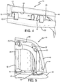
- an exemplary embodiment of an air maintenance tire system component protector of the present invention is indicated generally at 10.
- the protector 10 extends radially from the valve housing 26 to the dome 32 to engage and cover the connecting tubes 22 and 28 to protect them.
- the connecting tubes 22 and 28 typically are formed of a polymer, such as a flexible plastic, to enable the tubes to flex as the tire 12 undergoes cyclic deflection during rotation.
- the protector 10 thus includes a structure that enables it to flex, while remaining stable to provide secure protection for the tubes 22 and 28.
- the protector 10 includes a first end 40, a second end 42 and a mid-portion 44 disposed between the first and second ends.
- the first end 40 of the protector 10 provides rigid support and a secure connection of the protector to the dome 32. More particularly, the first end 40 is curved axially inboardly relative to the remainder of the protector 10 to provide a stable mounting platform against the dome 40.
- the first end 40 is secured to the dome 32 by a mechanical fastener, such as a screw 46.
- an opening 48 may be formed in the first end 40 of the protector 10, which aligns with the dome 32 in between the connecting tubes 22 and 28, thereby enabling the screw 46 to be secured to a solid area of the dome without adversely affecting the fluid connection of each respective connecting tube to the annular tube 20.
- the first end 40 of the protector 10 also preferably includes a boot 50.
- the boot 50 is formed of an elastomeric material, and covers the connection of each connecting tube 22 and 28 to the respective fittings 72 and 74 at the dome 32, which reinforces these connections.
- the boot 50 optionally contacts and seats on the dome 32 to enable the protector 10 to be supported by the dome.
- the first end 40 of the protector 10 also includes a pair of slots 52 that are formed in a radially inward surface 54 of the protector first end.
- each of the connecting tubes 22 and 28 snap into a respective one of the slots 52, enabling the first end 40 of the protector 10 to support the connecting tubes adjacent the dome 32.
- Such support enables the protector 10 to maintain a straight connection of each connecting tube 22 and 28 to the dome 32 to reduce any potential stress in the tubes, reduce abrasion of the tubes with other components such as connecting screws and improve the fatigue behavior of the tubes, all which desirably increase the life of the tubes.
- the second end 42 of the protector 10 provides rigid support and a secure connection of the protector to the valve housing 26.
- the valve housing 26 typically includes a nut 56 on its outboard surface that threads onto a bolt 58 of the valve housing.
- An opening 60 is formed in the second end 42 of the protector 10, which enables the bolt 58 to pass through the protector 10.
- a lip 62 is formed on the inner circumference of the opening 60, and the nut 56 engages the lip to secure the second end 42 of the protector 10 to the outboard surface of the valve housing 26.
- the second end 42 of the protector 10 preferably is also formed with a rounded edge 64 that curves axially inboardly to surround the radially inward perimeter edge of the outboard surface of the valve housing 26, thereby providing increased protection of the valve housing.
- the protector 10 is formed with a taper extending from the first end 40 to the mid-portion 44, and with a taper extending from the second end 42 to the mid-portion 44.
- the mid-portion 44 preferably is thinner than the first end 40 and the second end 42.
- the mid-portion includes a flexible member 66, such as a bellows.
- the bellows 66 may be a discrete member formed of a flexible material such as an elastomer, or it may be an integrated flexible feature formed in the mid-portion 44 of the connector 10.
- the flexible member 66 enables the protector 10 to flex along three planes of motion. Specifically, if the valve housing 26 has shifted circumferentially relative to the dome 32 and the valve housing and dome are thus misaligned, the flexible member 66 still enables a secure connection of the protector first end 40 to the dome and the second end 42 to the valve housing. If the valve housing 26 has shifted axially inboardly or axially outboardly relative to the dome 32, the flexible member 66 again enables a secure connection of the protector first end 40 to the dome and the second end 42 to the valve housing. Finally, as the tire 12 rotates and experiences cyclic deflection, the radial distance between the dome 32 and the valve housing 26 may change by up to about five (5) or six (6) millimeters. The flexible member 66 readily absorbs and thus accommodates such a change in radial distance, thereby maintaining a secure connection of the protector first end 40 to the dome 32 and the second end 42 to the valve housing 26.
- the protector 10 includes one or more pairs of connectors or clips 70 that are attached to an axially inboard surface 68 of the protector.
- the connectors or clips 70 snap onto and engage the connecting tubes 22 and 28 to retain the tubes adjacent the inboard surface 68 of the protector 10.
- the connectors 70 thus keep the connecting tubes 22 and 28 in a protected location, and by anchoring them to the protector 10, reduce undesirable vibration of the tubing as the tire 12 rotates.
- the protector 10 is formed of a light weight, yet stable, material.
- the protector 10 may be formed of rigid nylon polymer, which provides a weight between ten and fifteen grams for the protector 10.
- the protector 10 is easily installed after the air maintenance tire system 16 has been assembled, requiring no special steps or specialized tools.
- the protector 10 is easy to remove and/or replace, if needed.
- the protector 10 interfaces with existing components of the air maintenance tire system 16, so that no additional components or adaptations are needed to employ the protector.
- the air maintenance tire system component protector 10 of the present invention thus provides protection of the connecting tubes 22 and 28 and the valve housing 26 from debris impacts.
- the protector 10 retains the position of the connecting tubes 22 and 28 so that the tubes do not touch other components of the vehicle.
- anchoring the connecting tubes 22 and 28 to a streamlined structure that also covers the outboard surface of the valve housing 26, the protector also improves the aesthetic appearance of the connecting tubes and the valve housing.
- the protector 10 desirably provides protection of the tubes, which may be formed from a polymer, from potentially degrading ultraviolet light.
- the protector 10 supports the connection of the flexible connecting tubes 22 and 28 to the dome 32, improving the ability of the connecting tubes to withstand the stress created by the cyclic deflection of the tire 12 during rotation.
- the protector 10 also provides a stable anchor for the connecting tubes 22 and 28 to reduce the vibration of the tubes as the tire 12 rotates.
- the protector 10 desirably increases the life of the connecting tubes, as it reduces potential stress in the tubes, improves the fatigue performance of the tubes and reduces abrasion on the tubes at or near their respective connections to the dome 32 and the valve housing 26.
- the present invention also includes a method of protecting components of an air maintenance tire system.
- the method includes steps in accordance with the description that is presented above and shown in FIGS. 2 through 5 .
- the structure of the above-described air maintenance tire system component protector may be altered or rearranged, or components known to those skilled in the art omitted or added, without affecting the overall concept or operation of the invention.
- the protector 10 may be of a one-piece or a multi-piece construction, and/or may be formed of one material or multiple materials.
- the flexible member 66 may be formed of a different material than the rest of the protector 10, or from the same material as the rest of the protector.
Landscapes
- Engineering & Computer Science (AREA)
- Mechanical Engineering (AREA)
- Tires In General (AREA)
- Vehicle Cleaning, Maintenance, Repair, Refitting, And Outriggers (AREA)
Applications Claiming Priority (1)
| Application Number | Priority Date | Filing Date | Title |
|---|---|---|---|
| US15/186,841 US20170361668A1 (en) | 2016-06-20 | 2016-06-20 | Air maintenance tire system component protector |
Publications (1)
| Publication Number | Publication Date |
|---|---|
| EP3260312A1 true EP3260312A1 (de) | 2017-12-27 |
Family
ID=59077949
Family Applications (1)
| Application Number | Title | Priority Date | Filing Date |
|---|---|---|---|
| EP17176609.0A Withdrawn EP3260312A1 (de) | 2016-06-20 | 2017-06-19 | Reifen mit luftdruckaufrechterhaltungssystem mit komponentenschutz |
Country Status (5)
| Country | Link |
|---|---|
| US (1) | US20170361668A1 (de) |
| EP (1) | EP3260312A1 (de) |
| JP (1) | JP2017226410A (de) |
| CN (1) | CN107521295B (de) |
| BR (1) | BR102017013060A2 (de) |
Families Citing this family (3)
| Publication number | Priority date | Publication date | Assignee | Title |
|---|---|---|---|---|
| EP3312027B1 (de) * | 2016-10-19 | 2019-08-28 | The Goodyear Tire & Rubber Company | Verbindungsanordnung für ein lufterhaltendes reifensystem sowie lufterhaltendes reifensystem |
| US11454331B2 (en) | 2019-12-18 | 2022-09-27 | Form Create Llc | Valve cap assembly |
| JPWO2023038089A1 (de) * | 2021-09-13 | 2023-03-16 |
Citations (1)
| Publication number | Priority date | Publication date | Assignee | Title |
|---|---|---|---|---|
| EP2985159A1 (de) * | 2014-08-12 | 2016-02-17 | The Goodyear Tire & Rubber Company | Steuerregler und pumpsystem für reifen mit pneumatischer wartung |
Family Cites Families (4)
| Publication number | Priority date | Publication date | Assignee | Title |
|---|---|---|---|---|
| US1428241A (en) * | 1921-05-16 | 1922-09-05 | Kercher John | Vehicle wheel |
| US1624974A (en) * | 1926-06-14 | 1927-04-19 | Whitehead & Kales Co | Wheel rim and attachment therefor |
| US3077220A (en) * | 1961-05-25 | 1963-02-12 | Jr Andrew Fusco | Valve stem clip |
| US9533534B2 (en) * | 2014-10-22 | 2017-01-03 | The Goodyear Tire & Rubber Company | Air maintenance tire and valve assembly and method |
-
2016
- 2016-06-20 US US15/186,841 patent/US20170361668A1/en not_active Abandoned
-
2017
- 2017-06-15 JP JP2017117628A patent/JP2017226410A/ja active Pending
- 2017-06-19 BR BR102017013060-6A patent/BR102017013060A2/pt not_active IP Right Cessation
- 2017-06-19 EP EP17176609.0A patent/EP3260312A1/de not_active Withdrawn
- 2017-06-20 CN CN201710470180.3A patent/CN107521295B/zh active Active
Patent Citations (1)
| Publication number | Priority date | Publication date | Assignee | Title |
|---|---|---|---|---|
| EP2985159A1 (de) * | 2014-08-12 | 2016-02-17 | The Goodyear Tire & Rubber Company | Steuerregler und pumpsystem für reifen mit pneumatischer wartung |
Also Published As
| Publication number | Publication date |
|---|---|
| JP2017226410A (ja) | 2017-12-28 |
| CN107521295B (zh) | 2019-11-26 |
| US20170361668A1 (en) | 2017-12-21 |
| CN107521295A (zh) | 2017-12-29 |
| BR102017013060A2 (pt) | 2018-01-02 |
Similar Documents
| Publication | Publication Date | Title |
|---|---|---|
| EP3260312A1 (de) | Reifen mit luftdruckaufrechterhaltungssystem mit komponentenschutz | |
| EP3398791B1 (de) | Rad für ein lufterhaltendes reifensystem sowie lufterhaltendes reifensystem | |
| US9327562B2 (en) | Air maintenance tire assembly | |
| US10549586B1 (en) | Electronic unit for measuring operating parameters of a vehicle wheel | |
| EP3199386B1 (de) | Ventilschaftbasierter, luftaufrechterhaltender reifen und verfahren | |
| US9682599B1 (en) | On-wheel air maintenance system | |
| US20170113500A1 (en) | On-wheel air maintenance system | |
| US10513157B2 (en) | Connection assembly for an air maintenance tire | |
| US10189321B2 (en) | Air maintenance tire system component protector | |
| CN110891798A (zh) | 具有高度降低的轮辋凸缘的轮辋 | |
| US10189320B2 (en) | On-wheel air maintenance system | |
| EP3332994A1 (de) | Luftaufrechterhaltender reifen und ventilanordnung und verfahren | |
| EP3300931B1 (de) | Verbindungselement für einen luftwartungsreifen und verfahren zu dessen herstellung | |
| EP3176012B1 (de) | Luftwartungssystem und -verfahren für zwei reifen | |
| EP3170684B1 (de) | Ventilschaftbasierter, luftaufrechterhaltender reifen und verfahren | |
| EP3318429A1 (de) | Reifen mit pneumatischer wartung | |
| US10894452B2 (en) | Mounting member for an air maintenance tire | |
| US20230158831A1 (en) | Wheel-internal double beadlock system and methods thereof | |
| CN101687450A (zh) | 用于安装组件的放气阀 | |
| EP3272559A1 (de) | Verstärkte ventilgruppe zum aufpumpen von luftreifen |
Legal Events
| Date | Code | Title | Description |
|---|---|---|---|
| PUAI | Public reference made under article 153(3) epc to a published international application that has entered the european phase |
Free format text: ORIGINAL CODE: 0009012 |
|
| AK | Designated contracting states |
Kind code of ref document: A1 Designated state(s): AL AT BE BG CH CY CZ DE DK EE ES FI FR GB GR HR HU IE IS IT LI LT LU LV MC MK MT NL NO PL PT RO RS SE SI SK SM TR |
|
| AX | Request for extension of the european patent |
Extension state: BA ME |
|
| STAA | Information on the status of an ep patent application or granted ep patent |
Free format text: STATUS: REQUEST FOR EXAMINATION WAS MADE |
|
| 17P | Request for examination filed |
Effective date: 20180627 |
|
| RBV | Designated contracting states (corrected) |
Designated state(s): AL AT BE BG CH CY CZ DE DK EE ES FI FR GB GR HR HU IE IS IT LI LT LU LV MC MK MT NL NO PL PT RO RS SE SI SK SM TR |
|
| STAA | Information on the status of an ep patent application or granted ep patent |
Free format text: STATUS: THE APPLICATION HAS BEEN WITHDRAWN |
|
| 18W | Application withdrawn |
Effective date: 20191009 |