EP3260293A1 - Composite material structure - Google Patents
Composite material structure Download PDFInfo
- Publication number
- EP3260293A1 EP3260293A1 EP15882530.7A EP15882530A EP3260293A1 EP 3260293 A1 EP3260293 A1 EP 3260293A1 EP 15882530 A EP15882530 A EP 15882530A EP 3260293 A1 EP3260293 A1 EP 3260293A1
- Authority
- EP
- European Patent Office
- Prior art keywords
- metal member
- main surface
- composite material
- portions
- material structure
- Prior art date
- Legal status (The legal status is an assumption and is not a legal conclusion. Google has not performed a legal analysis and makes no representation as to the accuracy of the status listed.)
- Granted
Links
Images


Classifications
-
- B—PERFORMING OPERATIONS; TRANSPORTING
- B62—LAND VEHICLES FOR TRAVELLING OTHERWISE THAN ON RAILS
- B62D—MOTOR VEHICLES; TRAILERS
- B62D29/00—Superstructures, understructures, or sub-units thereof, characterised by the material thereof
- B62D29/001—Superstructures, understructures, or sub-units thereof, characterised by the material thereof characterised by combining metal and synthetic material
- B62D29/005—Superstructures, understructures, or sub-units thereof, characterised by the material thereof characterised by combining metal and synthetic material preformed metal and synthetic material elements being joined together, e.g. by adhesives
-
- B—PERFORMING OPERATIONS; TRANSPORTING
- B32—LAYERED PRODUCTS
- B32B—LAYERED PRODUCTS, i.e. PRODUCTS BUILT-UP OF STRATA OF FLAT OR NON-FLAT, e.g. CELLULAR OR HONEYCOMB, FORM
- B32B15/00—Layered products comprising a layer of metal
- B32B15/01—Layered products comprising a layer of metal all layers being exclusively metallic
- B32B15/016—Layered products comprising a layer of metal all layers being exclusively metallic all layers being formed of aluminium or aluminium alloys
-
- B—PERFORMING OPERATIONS; TRANSPORTING
- B32—LAYERED PRODUCTS
- B32B—LAYERED PRODUCTS, i.e. PRODUCTS BUILT-UP OF STRATA OF FLAT OR NON-FLAT, e.g. CELLULAR OR HONEYCOMB, FORM
- B32B15/00—Layered products comprising a layer of metal
- B32B15/04—Layered products comprising a layer of metal comprising metal as the main or only constituent of a layer, which is next to another layer of the same or of a different material
- B32B15/08—Layered products comprising a layer of metal comprising metal as the main or only constituent of a layer, which is next to another layer of the same or of a different material of synthetic resin
-
- B—PERFORMING OPERATIONS; TRANSPORTING
- B32—LAYERED PRODUCTS
- B32B—LAYERED PRODUCTS, i.e. PRODUCTS BUILT-UP OF STRATA OF FLAT OR NON-FLAT, e.g. CELLULAR OR HONEYCOMB, FORM
- B32B15/00—Layered products comprising a layer of metal
- B32B15/14—Layered products comprising a layer of metal next to a fibrous or filamentary layer
-
- B—PERFORMING OPERATIONS; TRANSPORTING
- B32—LAYERED PRODUCTS
- B32B—LAYERED PRODUCTS, i.e. PRODUCTS BUILT-UP OF STRATA OF FLAT OR NON-FLAT, e.g. CELLULAR OR HONEYCOMB, FORM
- B32B27/00—Layered products comprising a layer of synthetic resin
- B32B27/06—Layered products comprising a layer of synthetic resin as the main or only constituent of a layer, which is next to another layer of the same or of a different material
- B32B27/08—Layered products comprising a layer of synthetic resin as the main or only constituent of a layer, which is next to another layer of the same or of a different material of synthetic resin
-
- B—PERFORMING OPERATIONS; TRANSPORTING
- B32—LAYERED PRODUCTS
- B32B—LAYERED PRODUCTS, i.e. PRODUCTS BUILT-UP OF STRATA OF FLAT OR NON-FLAT, e.g. CELLULAR OR HONEYCOMB, FORM
- B32B3/00—Layered products comprising a layer with external or internal discontinuities or unevennesses, or a layer of non-planar form; Layered products having particular features of form
- B32B3/26—Layered products comprising a layer with external or internal discontinuities or unevennesses, or a layer of non-planar form; Layered products having particular features of form characterised by a particular shape of the outline of the cross-section of a continuous layer; characterised by a layer with cavities or internal voids ; characterised by an apertured layer
- B32B3/263—Layered products comprising a layer with external or internal discontinuities or unevennesses, or a layer of non-planar form; Layered products having particular features of form characterised by a particular shape of the outline of the cross-section of a continuous layer; characterised by a layer with cavities or internal voids ; characterised by an apertured layer characterised by a layer having non-uniform thickness
-
- B—PERFORMING OPERATIONS; TRANSPORTING
- B32—LAYERED PRODUCTS
- B32B—LAYERED PRODUCTS, i.e. PRODUCTS BUILT-UP OF STRATA OF FLAT OR NON-FLAT, e.g. CELLULAR OR HONEYCOMB, FORM
- B32B3/00—Layered products comprising a layer with external or internal discontinuities or unevennesses, or a layer of non-planar form; Layered products having particular features of form
- B32B3/26—Layered products comprising a layer with external or internal discontinuities or unevennesses, or a layer of non-planar form; Layered products having particular features of form characterised by a particular shape of the outline of the cross-section of a continuous layer; characterised by a layer with cavities or internal voids ; characterised by an apertured layer
- B32B3/266—Layered products comprising a layer with external or internal discontinuities or unevennesses, or a layer of non-planar form; Layered products having particular features of form characterised by a particular shape of the outline of the cross-section of a continuous layer; characterised by a layer with cavities or internal voids ; characterised by an apertured layer characterised by an apertured layer, the apertures going through the whole thickness of the layer, e.g. expanded metal, perforated layer, slit layer regular cells B32B3/12
-
- B—PERFORMING OPERATIONS; TRANSPORTING
- B32—LAYERED PRODUCTS
- B32B—LAYERED PRODUCTS, i.e. PRODUCTS BUILT-UP OF STRATA OF FLAT OR NON-FLAT, e.g. CELLULAR OR HONEYCOMB, FORM
- B32B3/00—Layered products comprising a layer with external or internal discontinuities or unevennesses, or a layer of non-planar form; Layered products having particular features of form
- B32B3/26—Layered products comprising a layer with external or internal discontinuities or unevennesses, or a layer of non-planar form; Layered products having particular features of form characterised by a particular shape of the outline of the cross-section of a continuous layer; characterised by a layer with cavities or internal voids ; characterised by an apertured layer
- B32B3/28—Layered products comprising a layer with external or internal discontinuities or unevennesses, or a layer of non-planar form; Layered products having particular features of form characterised by a particular shape of the outline of the cross-section of a continuous layer; characterised by a layer with cavities or internal voids ; characterised by an apertured layer characterised by a layer comprising a deformed thin sheet, i.e. the layer having its entire thickness deformed out of the plane, e.g. corrugated, crumpled
-
- B—PERFORMING OPERATIONS; TRANSPORTING
- B32—LAYERED PRODUCTS
- B32B—LAYERED PRODUCTS, i.e. PRODUCTS BUILT-UP OF STRATA OF FLAT OR NON-FLAT, e.g. CELLULAR OR HONEYCOMB, FORM
- B32B5/00—Layered products characterised by the non- homogeneity or physical structure, i.e. comprising a fibrous, filamentary, particulate or foam layer; Layered products characterised by having a layer differing constitutionally or physically in different parts
- B32B5/02—Layered products characterised by the non- homogeneity or physical structure, i.e. comprising a fibrous, filamentary, particulate or foam layer; Layered products characterised by having a layer differing constitutionally or physically in different parts characterised by structural features of a fibrous or filamentary layer
- B32B5/028—Net structure, e.g. spaced apart filaments bonded at the crossing points
-
- B—PERFORMING OPERATIONS; TRANSPORTING
- B32—LAYERED PRODUCTS
- B32B—LAYERED PRODUCTS, i.e. PRODUCTS BUILT-UP OF STRATA OF FLAT OR NON-FLAT, e.g. CELLULAR OR HONEYCOMB, FORM
- B32B5/00—Layered products characterised by the non- homogeneity or physical structure, i.e. comprising a fibrous, filamentary, particulate or foam layer; Layered products characterised by having a layer differing constitutionally or physically in different parts
- B32B5/14—Layered products characterised by the non- homogeneity or physical structure, i.e. comprising a fibrous, filamentary, particulate or foam layer; Layered products characterised by having a layer differing constitutionally or physically in different parts characterised by a layer differing constitutionally or physically in different parts, e.g. denser near its faces
- B32B5/142—Variation across the area of the layer
-
- B—PERFORMING OPERATIONS; TRANSPORTING
- B32—LAYERED PRODUCTS
- B32B—LAYERED PRODUCTS, i.e. PRODUCTS BUILT-UP OF STRATA OF FLAT OR NON-FLAT, e.g. CELLULAR OR HONEYCOMB, FORM
- B32B7/00—Layered products characterised by the relation between layers; Layered products characterised by the relative orientation of features between layers, or by the relative values of a measurable parameter between layers, i.e. products comprising layers having different physical, chemical or physicochemical properties; Layered products characterised by the interconnection of layers
- B32B7/04—Interconnection of layers
- B32B7/12—Interconnection of layers using interposed adhesives or interposed materials with bonding properties
-
- B—PERFORMING OPERATIONS; TRANSPORTING
- B62—LAND VEHICLES FOR TRAVELLING OTHERWISE THAN ON RAILS
- B62D—MOTOR VEHICLES; TRAILERS
- B62D25/00—Superstructure or monocoque structure sub-units; Parts or details thereof not otherwise provided for
- B62D25/20—Floors or bottom sub-units
-
- B—PERFORMING OPERATIONS; TRANSPORTING
- B32—LAYERED PRODUCTS
- B32B—LAYERED PRODUCTS, i.e. PRODUCTS BUILT-UP OF STRATA OF FLAT OR NON-FLAT, e.g. CELLULAR OR HONEYCOMB, FORM
- B32B2250/00—Layers arrangement
- B32B2250/03—3 layers
-
- B—PERFORMING OPERATIONS; TRANSPORTING
- B32—LAYERED PRODUCTS
- B32B—LAYERED PRODUCTS, i.e. PRODUCTS BUILT-UP OF STRATA OF FLAT OR NON-FLAT, e.g. CELLULAR OR HONEYCOMB, FORM
- B32B2250/00—Layers arrangement
- B32B2250/40—Symmetrical or sandwich layers, e.g. ABA, ABCBA, ABCCBA
-
- B—PERFORMING OPERATIONS; TRANSPORTING
- B32—LAYERED PRODUCTS
- B32B—LAYERED PRODUCTS, i.e. PRODUCTS BUILT-UP OF STRATA OF FLAT OR NON-FLAT, e.g. CELLULAR OR HONEYCOMB, FORM
- B32B2307/00—Properties of the layers or laminate
- B32B2307/70—Other properties
- B32B2307/706—Anisotropic
-
- B—PERFORMING OPERATIONS; TRANSPORTING
- B32—LAYERED PRODUCTS
- B32B—LAYERED PRODUCTS, i.e. PRODUCTS BUILT-UP OF STRATA OF FLAT OR NON-FLAT, e.g. CELLULAR OR HONEYCOMB, FORM
- B32B2307/00—Properties of the layers or laminate
- B32B2307/70—Other properties
- B32B2307/732—Dimensional properties
-
- B—PERFORMING OPERATIONS; TRANSPORTING
- B32—LAYERED PRODUCTS
- B32B—LAYERED PRODUCTS, i.e. PRODUCTS BUILT-UP OF STRATA OF FLAT OR NON-FLAT, e.g. CELLULAR OR HONEYCOMB, FORM
- B32B2605/00—Vehicles
-
- B—PERFORMING OPERATIONS; TRANSPORTING
- B32—LAYERED PRODUCTS
- B32B—LAYERED PRODUCTS, i.e. PRODUCTS BUILT-UP OF STRATA OF FLAT OR NON-FLAT, e.g. CELLULAR OR HONEYCOMB, FORM
- B32B2605/00—Vehicles
- B32B2605/003—Interior finishings
-
- B—PERFORMING OPERATIONS; TRANSPORTING
- B32—LAYERED PRODUCTS
- B32B—LAYERED PRODUCTS, i.e. PRODUCTS BUILT-UP OF STRATA OF FLAT OR NON-FLAT, e.g. CELLULAR OR HONEYCOMB, FORM
- B32B2605/00—Vehicles
- B32B2605/08—Cars
Definitions
- the present invention relates to a composite material structure of metal and fiber-reinforced resin.
- Patent Document 1 International Publication No. 99/10168
- an object of the present invention is to provide a composite material structure capable of reducing the effect of the difference in thermal expansion coefficients between metal and fiber-reinforced resin.
- the composite material structure comprises a metal member and a resin member.
- the metal member is planarly formed such that the thermal expansion coefficient in a first direction along a main surface is larger than the thermal expansion coefficient in a second direction along the main surface that is orthogonal to the first direction.
- the resin member made of fiber-reinforced resin, is bonded to the main surface of the metal member and is formed such that the fiber quantity along the second direction is larger than the fiber quantity along the first direction.
- the composite material structure 1 is applied to, for example, a floor panel 11 provided in a car body front part 10 of an automobile, as illustrated in Figures 1 and 2 .
- the composite material structure 1 can be applied to a dash panel or a roof panel of the car body, or can be applied to a side shell 12, a floor tunnel 13, or a cross member 14 provided on the car body front part 10.
- the composite material structure 1 comprises a metal member 2 that is formed of metal with a planarly shape and sheet-like resin members 4 that are made of fiber-reinforced resin and bonded to both main surfaces of the metal member 2, as illustrated in Figure 3 .
- the metal member 2 is made of a light metal, such as aluminum, aluminum alloy, magnesium, or magnesium alloy.
- the resin members 4 are made of fiber-reinforced resin having a smaller thermal expansion coefficient than the material of the metal member 2, such as carbon fiber-reinforced plastic (CFRP).
- CFRP carbon fiber-reinforced plastic
- the metal member 2 is formed such that the thermal expansion coefficient in a first direction (X-axis direction) along a main surface is larger than the thermal expansion coefficient in a second direction (Y-axis direction) along the main surface and that is orthogonal to the first direction.
- the metal member 2 is formed by, for example, extrusion molding wherein the first direction is the extrusion direction of metal.
- the metal member 2 can be formed by other processing methods, such as bending or casting.
- the metal member 2 is formed such that the cross-sectional shape, as viewed from the first direction, is uniform.
- the metal member 2 comprises a plurality of main surface portions 21, the outside surfaces of which constitute the main surface of the metal member 2, and a plurality of connecting portions 23 that connect to the end portions 22 of the main surface portions 21 on the other surface side, by being bent at each of the end portions 22 in the second direction of the main surface portions 21.
- the main surface portions 21 and the connecting portions 23 are each planarly shaped. By being connected as to be bent at the end portions 22, the main surface portions 21 and the connecting portions 23 can enhance the strength of the metal member 2 in a third direction (Z-axis direction), which is orthogonal to the first direction and the second direction.
- the main surface portions 21 are disposed on each of the two surface sides of the metal member 2 in the third direction, such that the end portion 22 and the end portion 22 of another adjacent main surface portion 21 are each separated by a gap 20. That is, the metal member 2 is formed such that the main surfaces are continuous in the first direction and discontinuous in the second direction.
- the two main surfaces of the metal member 2 and the resin members 4 are bonded to each other by an adhesive 3.
- the adhesive 3 has several thin walled portions 31 formed to have a smaller thickness than the other portions.
- the thin walled portions 31 are formed by thick walled portions 24 that are formed on the outer side surface of the main surface portions 21 to have a larger thickness than the other portions.
- the thick walled portions 24 and the thin walled portions 31 are periodically positioned in the second direction.
- the thick walled portions 24 are, for example, located in a central portion of each of the main surface portions 21 in the second direction.
- the adhesive 3 has anchor portions 32 that protrude in the inner side direction, formed by the adhesive entering the gaps 20 between two opposing ones of the end portions 22.
- the adhesive 3 generates an anchor effect by having the anchor portions 32 that are between two opposing ones of the end portions 22 to enhance the bonding force with respect to the metal member 2.
- the resin members 4 are formed such that a quantity of the fiber 42 along the second direction is larger than a quantity of the fiber 41 along the first direction, as illustrated in Figure 4 . That is, the resin members 4 are formed such that the thermal expansion coefficient in the second direction is larger than the thermal expansion coefficient in the first direction.
- the metal member 2 before thermal expansion is illustrated by the chain double-dashed lines, and the metal member 2 after thermal expansion is illustrated by the solid lines.
- the main surface portion 21 is thermally expanded, the main surface portion is elongated in the second direction, and the gaps 20 between two opposing ones of the end portions 22 becomes narrow.
- the gaps 20 function as a margin at the time of thermal expansion, the thermal expansion coefficient of the metal member 2 in the second direction becomes smaller than the thermal expansion coefficient in the first direction.
- the adhesive 3 strongly bonds the metal member 2 and the resin members 4 at the thin walled portions 31.
- the adhesive 3 in the thickly formed regions, excluding the thin walled portions 31 undergoes shearing deformation that is greater than in the thin walled portions 31 between the main surface portions 21 and the resin members 4.
- the adhesive 3 functions as a buffer layer that absorbs the difference in the amount of displacement, caused by thermal expansion, between the metal member 2 and the resin members 4. Since the thin walled portions 31 are positioned in the central portion of each of the main surface portions 21 in the second direction, the shearing deformation is small, and the damage is small.
- the gaps 20 are formed to have a width with which the matrix resin 40 of the resin member 4 and the adhesive 3 (refer to Figure 4 ) do not intrude into the region that surpasses the main surface portion 21 of the metal member 2 (the region between the connecting portions 23).
- the widths of the gaps 20 are, for example, several mm, and can be about 1-2 mm, when the width of each of the main surface portions 21 in the second direction is about 20-30 mm.
- the gaps 20 prevent the matrix resin 40 from flowing in the inner side direction of the metal member 2, when molding the matrix resin 40 against the metal member 2, to which the fibers 41, 42 are disposed.
- the metal member 2 and the resin members 4 are bonded such that the fibers 42 are densely oriented along the direction in which the thermal expansion coefficient of the metal member 2 is small, it is possible to reduce the effect of the difference in the thermal expansion coefficients between the metal and the fiber-reinforced resin. Therefore, other than a special adhesive becoming unnecessary when using an adhesive, it becomes easy to mold the matrix resin 40 against the metal member 2 (resin transfer molding: RTM).
- the main surfaces of the metal member 2 are formed as continuous in the first direction and discontinuous in the second direction, it is possible to easily form the metal member 2 having a smaller thermal expansion coefficient in the second direction by extrusion molding, or the like.
- the adhesive resin 3 having thin walled portions 31 it is possible to strongly bond the metal member 2 and the resin members 4 at the thin walled portions 31. Furthermore, by periodically positioning the thin walled portions 31 in the second direction, the adhesive 3 functions as an anchor when curing, and it is possible to reduce warping of the composite material structure 1.
- a composite material structure 1A according to a modified example of the embodiment of the present invention comprises a metal member 2A, in which main surface portions 21A on both sides in the third direction are connected by connecting portions 23A that connect in locations away from end portions 22A of the main surface portions 21A, as illustrated in Figure 6 .
- the main surface portions 21A are disposed on each of the two surface sides of the metal member 2A in the third direction, such that the end portion 22A and the end portion 22A of another adjacent main surface portion 21A are each separated by a gap 20A.
- the connecting portions 23A are formed, for example, along the third direction.
- the metal member 2A is formed such that the thermal expansion coefficient in the first direction is larger than the thermal expansion coefficient in the second direction.
- the metal member 2A is formed such that the cross-sectional shape as viewed from the first direction is constant.
- the thick walled portions 24 can be disposed displaced from the central portion of each main surface portion 21 in the second direction, as illustrated in Figure 7 . Additionally, it is not necessary for the pitch (pitch) at which the thick walled portions 24 and the thin walled portions 31 are arranged in the second direction to match the pitch of the main surface portions 21, as long as the portions are periodically positioned, as illustrated in Figure 7 .
- the present invention it is possible to provide a composite material structure capable of reducing the effect of the difference in the thermal expansion coefficients between metal and fiber-reinforced resin, by preferentially orienting the fibers of the fiber-reinforced resin along a direction in which the thermal expansion coefficient of the metal member is small.
Landscapes
- Engineering & Computer Science (AREA)
- Chemical & Material Sciences (AREA)
- Combustion & Propulsion (AREA)
- Transportation (AREA)
- Mechanical Engineering (AREA)
- Architecture (AREA)
- Structural Engineering (AREA)
- Laminated Bodies (AREA)
- Body Structure For Vehicles (AREA)
Abstract
Description
- The present invention relates to a composite material structure of metal and fiber-reinforced resin.
- In order to efficiently absorb an input load from the outside, a technique to bond carbon fiber-reinforced plastic (CFRP) to a load receiving part made of light metal, such as aluminum, aluminum alloy, magnesium, or magnesium alloy, has been disclosed (refer to Patent Document 1).
- Patent Document 1: International Publication No.
99/10168 - However, in the technique disclosed in
Patent Document 1, since the thermal expansion coefficients of the light metal and the CFRP are different, a special adhesive is necessary in order to absorb the difference in the amount of elongation deformation due to heat after bonding, and it is difficult to mold the light metal with the matrix resin of the CFRP. - In view of the problems described above, an object of the present invention is to provide a composite material structure capable of reducing the effect of the difference in thermal expansion coefficients between metal and fiber-reinforced resin.
- The composite material structure comprises a metal member and a resin member. The metal member is planarly formed such that the thermal expansion coefficient in a first direction along a main surface is larger than the thermal expansion coefficient in a second direction along the main surface that is orthogonal to the first direction. The resin member, made of fiber-reinforced resin, is bonded to the main surface of the metal member and is formed such that the fiber quantity along the second direction is larger than the fiber quantity along the first direction.
-
- [
Figure 1 ] is a perspective view illustrating a floor panel of an automobile comprising a composite material structure according to an embodiment of the present invention. - [
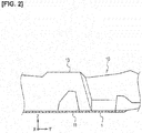
Figure 2 ] is a partial, cross-sectional view taken along line A-A inFigure 1 . - [
Figure 3 ] is a cross-sectional view illustrating the composite material structure according to the embodiment of the present invention. - [
Figure 4 ] is a plan view illustrating a resin material provided to the composite material structure according to the embodiment of the present invention. - [
Figure 5 ] is a cross-sectional view illustrating a state in which thermal expansion has occurred in the metal material provided to the composite material structure according to the embodiment of the present invention. - [
Figure 6 ] is a cross-sectional view illustrating a modified example of the composite material structure according to the embodiment of the present invention. - [
Figure 7 ] is a cross-sectional view illustrating the composite material structure according to another embodiment of the present invention. - Illustrative embodiments of the present invention will be described with reference to the drawings. In the explanations of the drawings, the same or similar elements are given the same or similar reference symbols, and overlapping explanations are omitted. The drawings are schematic, and the relationships and the ratios of the dimensions can be different from actual ratios.
- The
composite material structure 1 according to the embodiment of the present invention is applied to, for example, afloor panel 11 provided in a carbody front part 10 of an automobile, as illustrated inFigures 1 and2 . Alternatively, thecomposite material structure 1 can be applied to a dash panel or a roof panel of the car body, or can be applied to aside shell 12, afloor tunnel 13, or across member 14 provided on the carbody front part 10. - The
composite material structure 1 comprises ametal member 2 that is formed of metal with a planarly shape and sheet-like resin members 4 that are made of fiber-reinforced resin and bonded to both main surfaces of themetal member 2, as illustrated inFigure 3 . Themetal member 2 is made of a light metal, such as aluminum, aluminum alloy, magnesium, or magnesium alloy. Theresin members 4 are made of fiber-reinforced resin having a smaller thermal expansion coefficient than the material of themetal member 2, such as carbon fiber-reinforced plastic (CFRP). - The
metal member 2 is formed such that the thermal expansion coefficient in a first direction (X-axis direction) along a main surface is larger than the thermal expansion coefficient in a second direction (Y-axis direction) along the main surface and that is orthogonal to the first direction. Themetal member 2 is formed by, for example, extrusion molding wherein the first direction is the extrusion direction of metal. Themetal member 2 can be formed by other processing methods, such as bending or casting. - The
metal member 2 is formed such that the cross-sectional shape, as viewed from the first direction, is uniform. Themetal member 2 comprises a plurality ofmain surface portions 21, the outside surfaces of which constitute the main surface of themetal member 2, and a plurality of connectingportions 23 that connect to theend portions 22 of themain surface portions 21 on the other surface side, by being bent at each of theend portions 22 in the second direction of themain surface portions 21. Themain surface portions 21 and the connectingportions 23 are each planarly shaped. By being connected as to be bent at theend portions 22, themain surface portions 21 and the connectingportions 23 can enhance the strength of themetal member 2 in a third direction (Z-axis direction), which is orthogonal to the first direction and the second direction. - The
main surface portions 21 are disposed on each of the two surface sides of themetal member 2 in the third direction, such that theend portion 22 and theend portion 22 of another adjacentmain surface portion 21 are each separated by agap 20. That is, themetal member 2 is formed such that the main surfaces are continuous in the first direction and discontinuous in the second direction. - The two main surfaces of the
metal member 2 and theresin members 4 are bonded to each other by an adhesive 3. Theadhesive 3 has several thinwalled portions 31 formed to have a smaller thickness than the other portions. The thinwalled portions 31 are formed by thickwalled portions 24 that are formed on the outer side surface of themain surface portions 21 to have a larger thickness than the other portions. The thickwalled portions 24 and the thinwalled portions 31 are periodically positioned in the second direction. The thickwalled portions 24 are, for example, located in a central portion of each of themain surface portions 21 in the second direction. - The
adhesive 3 hasanchor portions 32 that protrude in the inner side direction, formed by the adhesive entering thegaps 20 between two opposing ones of theend portions 22. Theadhesive 3 generates an anchor effect by having theanchor portions 32 that are between two opposing ones of theend portions 22 to enhance the bonding force with respect to themetal member 2. - The
resin members 4 are formed such that a quantity of thefiber 42 along the second direction is larger than a quantity of thefiber 41 along the first direction, as illustrated inFigure 4 . That is, theresin members 4 are formed such that the thermal expansion coefficient in the second direction is larger than the thermal expansion coefficient in the first direction. - When the
composite material structure 1 is heated, thermal expansion occurs in themetal member 2, as illustrated inFigure 5 . InFigure 5 , themetal member 2 before thermal expansion is illustrated by the chain double-dashed lines, and themetal member 2 after thermal expansion is illustrated by the solid lines. When themain surface portion 21 is thermally expanded, the main surface portion is elongated in the second direction, and thegaps 20 between two opposing ones of theend portions 22 becomes narrow. Thegaps 20 function as a margin at the time of thermal expansion, the thermal expansion coefficient of themetal member 2 in the second direction becomes smaller than the thermal expansion coefficient in the first direction. - The
adhesive 3 strongly bonds themetal member 2 and theresin members 4 at the thinwalled portions 31. When thecomposite material structure 1 is heated, since themetal member 2 has a larger thermal expansion coefficient than theresin members 4, theadhesive 3 in the thickly formed regions, excluding the thinwalled portions 31, undergoes shearing deformation that is greater than in the thinwalled portions 31 between themain surface portions 21 and theresin members 4. By undergoing shearing deformation, the adhesive 3 functions as a buffer layer that absorbs the difference in the amount of displacement, caused by thermal expansion, between themetal member 2 and theresin members 4. Since the thinwalled portions 31 are positioned in the central portion of each of themain surface portions 21 in the second direction, the shearing deformation is small, and the damage is small. - The
gaps 20 are formed to have a width with which the matrix resin 40 of theresin member 4 and the adhesive 3 (refer toFigure 4 ) do not intrude into the region that surpasses themain surface portion 21 of the metal member 2 (the region between the connecting portions 23). The widths of thegaps 20 are, for example, several mm, and can be about 1-2 mm, when the width of each of themain surface portions 21 in the second direction is about 20-30 mm. Thegaps 20 prevent thematrix resin 40 from flowing in the inner side direction of themetal member 2, when molding thematrix resin 40 against themetal member 2, to which thefibers - According to the
composite material structure 1 according to the embodiment of the present invention, since themetal member 2 and theresin members 4 are bonded such that thefibers 42 are densely oriented along the direction in which the thermal expansion coefficient of themetal member 2 is small, it is possible to reduce the effect of the difference in the thermal expansion coefficients between the metal and the fiber-reinforced resin. Therefore, other than a special adhesive becoming unnecessary when using an adhesive, it becomes easy to mold thematrix resin 40 against the metal member 2 (resin transfer molding: RTM). - In addition, according to the
composite material structure 1, since the main surfaces of themetal member 2 are formed as continuous in the first direction and discontinuous in the second direction, it is possible to easily form themetal member 2 having a smaller thermal expansion coefficient in the second direction by extrusion molding, or the like. - In addition, according to the
composite material structure 1, by theadhesive resin 3 having thinwalled portions 31, it is possible to strongly bond themetal member 2 and theresin members 4 at the thinwalled portions 31. Furthermore, by periodically positioning the thinwalled portions 31 in the second direction, the adhesive 3 functions as an anchor when curing, and it is possible to reduce warping of thecomposite material structure 1. - In the embodiment described above, an example of the
metal member 2 was described in which the two surface sides of themain surface portions 21 are connected by connectingportions 23 at theend portions 22; however, the same action and effects as thecomposite material structure 1 can be exerted even if the cross-sectional shape of themetal member 2 is another shape. - A
composite material structure 1A according to a modified example of the embodiment of the present invention comprises ametal member 2A, in whichmain surface portions 21A on both sides in the third direction are connected by connectingportions 23A that connect in locations away fromend portions 22A of themain surface portions 21A, as illustrated inFigure 6 . Themain surface portions 21A are disposed on each of the two surface sides of themetal member 2A in the third direction, such that theend portion 22A and theend portion 22A of another adjacentmain surface portion 21A are each separated by agap 20A. The connectingportions 23A are formed, for example, along the third direction. - In the same manner as the
metal member 2, themetal member 2A is formed such that the thermal expansion coefficient in the first direction is larger than the thermal expansion coefficient in the second direction. In addition, themetal member 2A is formed such that the cross-sectional shape as viewed from the first direction is constant. - In
Figure 6 , a case in which the connectingportions 23 are along the third direction is illustrated, but this is just an illustrative embodiment, and the connectingportions 23 can have inclinations with respect to the third direction as well. In this case, in the same manner asFigure 3 , etc., the directions in which the connectingportions 23 are tilted are preferably alternated in the second direction. - As described above, the present invention was described according to the illustrative embodiment described above; however, the discussion and drawings that constitute a portion of this disclosure should not be understood as limiting the present invention. From this disclosure, various alternative embodiments, examples, and operational techniques should be apparent to those skilled in the art.
- For example, in the embodiment described above, the thick
walled portions 24 can be disposed displaced from the central portion of eachmain surface portion 21 in the second direction, as illustrated inFigure 7 . Additionally, it is not necessary for the pitch (pitch) at which the thickwalled portions 24 and the thinwalled portions 31 are arranged in the second direction to match the pitch of themain surface portions 21, as long as the portions are periodically positioned, as illustrated inFigure 7 . - Other than the above, it goes without saying that the present invention includes various embodiments not described herein, such as configurations in which the above-described configurations are applied to each other. Therefore, the technical scope of the present invention is determined only by the matter specifying the invention according to the claims that are pertinent to the description above.
- According to the present invention, it is possible to provide a composite material structure capable of reducing the effect of the difference in the thermal expansion coefficients between metal and fiber-reinforced resin, by preferentially orienting the fibers of the fiber-reinforced resin along a direction in which the thermal expansion coefficient of the metal member is small.
-
- 1, 1A Composite material structure
- 2, 2A Metal member
- 3 Adhesive
- 4 Resin member
- 20 Gap
- 21, 21A Main surface portion (main surface)
- 31 Thin walled portion
- 41, 42 Fiber
Claims (4)
- A composite material structure comprising:a metal member formed in a planar shape such that a thermal expansion coefficient in a first direction along a main surface is larger than a thermal expansion coefficient in a second direction along the main surface that is orthogonal to the first direction; anda resin member bonded to the main surface of the metal member, and made of fiber-reinforced resin having a fiber quantity along the second direction that is larger than a fiber quantity along the first direction.
- The composite material structure according to claim 1, wherein the metal member is formed such that main surface is continuous in the first direction and discontinuous in the second direction.
- The composite material structure according to claim 1 or 2, wherein
the main surface of the metal member and the resin member are bonded to each other by an adhesive; and
the adhesive has thin walled portions that are formed to have a smaller thickness than other portions. - The composite material structure according to claim 3, wherein the thin walled portions are periodically positioned in the second direction.
Applications Claiming Priority (1)
| Application Number | Priority Date | Filing Date | Title |
|---|---|---|---|
| PCT/JP2015/054103 WO2016132425A1 (en) | 2015-02-16 | 2015-02-16 | Composite material structure |
Publications (3)
| Publication Number | Publication Date |
|---|---|
| EP3260293A1 true EP3260293A1 (en) | 2017-12-27 |
| EP3260293A4 EP3260293A4 (en) | 2018-05-02 |
| EP3260293B1 EP3260293B1 (en) | 2019-06-19 |
Family
ID=56692108
Family Applications (1)
| Application Number | Title | Priority Date | Filing Date |
|---|---|---|---|
| EP15882530.7A Active EP3260293B1 (en) | 2015-02-16 | 2015-02-16 | Composite material structure |
Country Status (5)
| Country | Link |
|---|---|
| US (1) | US10065687B2 (en) |
| EP (1) | EP3260293B1 (en) |
| JP (1) | JP6376274B2 (en) |
| CN (1) | CN107206750B (en) |
| WO (1) | WO2016132425A1 (en) |
Families Citing this family (5)
| Publication number | Priority date | Publication date | Assignee | Title |
|---|---|---|---|---|
| RU173962U1 (en) * | 2017-05-11 | 2017-09-22 | Виктор Николаевич Молодцев | Sandwich - floor panel |
| JP6998828B2 (en) * | 2018-05-10 | 2022-02-04 | 日産自動車株式会社 | Composite structure |
| WO2019243855A1 (en) * | 2018-06-18 | 2019-12-26 | 日産自動車株式会社 | Joined structure and method for producing same |
| CN113978562B (en) * | 2021-11-03 | 2022-10-11 | 上海研化实业有限公司 | Threshold beam structure |
| JP2023111217A (en) * | 2022-01-31 | 2023-08-10 | トヨタ自動車株式会社 | Vehicular floor structure and vehicle manufacturing method |
Family Cites Families (15)
| Publication number | Priority date | Publication date | Assignee | Title |
|---|---|---|---|---|
| JPS5045375U (en) * | 1973-08-22 | 1975-05-07 | ||
| JPS5624568B2 (en) | 1973-08-29 | 1981-06-06 | ||
| US4888247A (en) | 1986-08-27 | 1989-12-19 | General Electric Company | Low-thermal-expansion, heat conducting laminates having layers of metal and reinforced polymer matrix composite |
| US6468613B1 (en) | 1997-08-21 | 2002-10-22 | Toray Industries, Inc. | Light metal/CFRP structural member |
| JP2001088793A (en) * | 1999-09-20 | 2001-04-03 | Mitsubishi Heavy Ind Ltd | Composite material structural body and aircraft tail unit using it |
| US20030008105A1 (en) * | 2000-01-21 | 2003-01-09 | Ulrich Haack | Metal-plastic composite made from long-fiber-reinforced thermoplastics |
| US7851048B2 (en) * | 2008-02-12 | 2010-12-14 | Milliken & Co. | Fiber reinforced core panel |
| JP5471267B2 (en) * | 2009-10-07 | 2014-04-16 | トヨタ自動車株式会社 | Heterogeneous material composite |
| CN201659721U (en) * | 2010-03-05 | 2010-12-01 | 铂邑科技股份有限公司 | Composite plate of metal base plate combined with external decoration layer |
| NL2005536C2 (en) * | 2010-10-15 | 2012-04-17 | Univ Delft Tech | Aircraft wing and fiber metal laminate forming part of such an aircraft wing. |
| CN102416714B (en) * | 2011-08-16 | 2014-04-23 | 西安交通大学 | Lattice metal-foamed aluminium composite material and preparation method thereof |
| CN102416713B (en) * | 2011-08-16 | 2014-04-23 | 西安交通大学 | Lattice-gradient foamed aluminum composite material and preparation method thereof |
| US20150197068A1 (en) * | 2012-07-10 | 2015-07-16 | Wayne State University | Method of making composite materials |
| JP2015024679A (en) * | 2013-07-24 | 2015-02-05 | トヨタ自動車株式会社 | Panel member |
| CN104197115A (en) | 2014-09-26 | 2014-12-10 | 安徽正石新型建材有限公司 | Drainage composite pipe |
-
2015
- 2015-02-16 JP JP2017500490A patent/JP6376274B2/en not_active Expired - Fee Related
- 2015-02-16 EP EP15882530.7A patent/EP3260293B1/en active Active
- 2015-02-16 WO PCT/JP2015/054103 patent/WO2016132425A1/en active Application Filing
- 2015-02-16 US US15/546,022 patent/US10065687B2/en active Active
- 2015-02-16 CN CN201580075221.8A patent/CN107206750B/en active Active
Also Published As
| Publication number | Publication date |
|---|---|
| JPWO2016132425A1 (en) | 2017-10-26 |
| US10065687B2 (en) | 2018-09-04 |
| WO2016132425A1 (en) | 2016-08-25 |
| US20180022395A1 (en) | 2018-01-25 |
| EP3260293A4 (en) | 2018-05-02 |
| CN107206750B (en) | 2019-03-01 |
| JP6376274B2 (en) | 2018-08-22 |
| CN107206750A (en) | 2017-09-26 |
| EP3260293B1 (en) | 2019-06-19 |
Similar Documents
| Publication | Publication Date | Title |
|---|---|---|
| US10065687B2 (en) | Composite material structure | |
| US10442002B2 (en) | Manufacturing of components of a vehicle using additive layer manufacturing | |
| EP3098061B1 (en) | Vehicle member joining structure | |
| KR102033645B1 (en) | Vehicle body structure | |
| CN108216089B (en) | Vehicle body structure | |
| US9931914B2 (en) | Bonding structure of vehicle members and bonding structure of backdoor | |
| JP6396513B2 (en) | Resin reinforced metal parts | |
| CN105313990A (en) | Structure formed by multiple parts | |
| JP6853415B2 (en) | Profile strip structure | |
| EP2674350B1 (en) | Attachment arrangement for vehicle | |
| US10569808B2 (en) | Motor vehicle reinforced structural element system | |
| EP3015345A1 (en) | Structure for lower part of vehicle body | |
| JP2008281429A (en) | Bonding strength evaluating method of double wrap coupling | |
| EP3029339A1 (en) | Joint, and aircraft structure | |
| JP6317313B2 (en) | Bonding structure of metal member and FRP member | |
| JP2017081231A (en) | Vehicle body frame structure | |
| KR102545428B1 (en) | Systems of sealing and reinforcing structural elements | |
| JP6998828B2 (en) | Composite structure | |
| KR101820547B1 (en) | Reinforcement aligned with axis of load | |
| JP2007309470A (en) | Lap joint | |
| JP5724457B2 (en) | Body structure | |
| JP3940100B2 (en) | Architectural composite plate with metal reinforcement | |
| JP2007321424A (en) | Building panel | |
| JP2008081007A (en) | Vehicle body front part structure |
Legal Events
| Date | Code | Title | Description |
|---|---|---|---|
| STAA | Information on the status of an ep patent application or granted ep patent |
Free format text: STATUS: THE INTERNATIONAL PUBLICATION HAS BEEN MADE |
|
| PUAI | Public reference made under article 153(3) epc to a published international application that has entered the european phase |
Free format text: ORIGINAL CODE: 0009012 |
|
| STAA | Information on the status of an ep patent application or granted ep patent |
Free format text: STATUS: REQUEST FOR EXAMINATION WAS MADE |
|
| 17P | Request for examination filed |
Effective date: 20170824 |
|
| AK | Designated contracting states |
Kind code of ref document: A1 Designated state(s): AL AT BE BG CH CY CZ DE DK EE ES FI FR GB GR HR HU IE IS IT LI LT LU LV MC MK MT NL NO PL PT RO RS SE SI SK SM TR |
|
| AX | Request for extension of the european patent |
Extension state: BA ME |
|
| A4 | Supplementary search report drawn up and despatched |
Effective date: 20180405 |
|
| RIC1 | Information provided on ipc code assigned before grant |
Ipc: B32B 5/02 20060101ALI20180329BHEP Ipc: B32B 15/08 20060101AFI20180329BHEP Ipc: B32B 15/01 20060101ALI20180329BHEP Ipc: B32B 15/14 20060101ALI20180329BHEP Ipc: B32B 27/08 20060101ALI20180329BHEP Ipc: B62D 25/20 20060101ALI20180329BHEP Ipc: B32B 3/28 20060101ALI20180329BHEP Ipc: B32B 5/14 20060101ALI20180329BHEP Ipc: B32B 3/26 20060101ALI20180329BHEP Ipc: B32B 7/12 20060101ALI20180329BHEP |
|
| DAX | Request for extension of the european patent (deleted) | ||
| GRAP | Despatch of communication of intention to grant a patent |
Free format text: ORIGINAL CODE: EPIDOSNIGR1 |
|
| STAA | Information on the status of an ep patent application or granted ep patent |
Free format text: STATUS: GRANT OF PATENT IS INTENDED |
|
| RIC1 | Information provided on ipc code assigned before grant |
Ipc: B32B 5/02 20060101ALI20190205BHEP Ipc: B32B 7/12 20060101ALI20190205BHEP Ipc: B62D 25/20 20060101ALI20190205BHEP Ipc: B32B 15/01 20060101ALI20190205BHEP Ipc: B32B 5/14 20060101ALI20190205BHEP Ipc: B32B 3/28 20060101ALI20190205BHEP Ipc: B32B 15/08 20060101AFI20190205BHEP Ipc: B62D 29/00 20060101ALI20190205BHEP Ipc: B32B 15/14 20060101ALI20190205BHEP Ipc: B32B 3/26 20060101ALI20190205BHEP Ipc: B32B 27/08 20060101ALI20190205BHEP |
|
| INTG | Intention to grant announced |
Effective date: 20190305 |
|
| GRAS | Grant fee paid |
Free format text: ORIGINAL CODE: EPIDOSNIGR3 |
|
| GRAA | (expected) grant |
Free format text: ORIGINAL CODE: 0009210 |
|
| STAA | Information on the status of an ep patent application or granted ep patent |
Free format text: STATUS: THE PATENT HAS BEEN GRANTED |
|
| AK | Designated contracting states |
Kind code of ref document: B1 Designated state(s): AL AT BE BG CH CY CZ DE DK EE ES FI FR GB GR HR HU IE IS IT LI LT LU LV MC MK MT NL NO PL PT RO RS SE SI SK SM TR |
|
| REG | Reference to a national code |
Ref country code: GB Ref legal event code: FG4D |
|
| REG | Reference to a national code |
Ref country code: CH Ref legal event code: EP |
|
| REG | Reference to a national code |
Ref country code: IE Ref legal event code: FG4D |
|
| REG | Reference to a national code |
Ref country code: DE Ref legal event code: R096 Ref document number: 602015032519 Country of ref document: DE |
|
| REG | Reference to a national code |
Ref country code: AT Ref legal event code: REF Ref document number: 1144946 Country of ref document: AT Kind code of ref document: T Effective date: 20190715 |
|
| REG | Reference to a national code |
Ref country code: NL Ref legal event code: MP Effective date: 20190619 |
|
| PG25 | Lapsed in a contracting state [announced via postgrant information from national office to epo] |
Ref country code: FI Free format text: LAPSE BECAUSE OF FAILURE TO SUBMIT A TRANSLATION OF THE DESCRIPTION OR TO PAY THE FEE WITHIN THE PRESCRIBED TIME-LIMIT Effective date: 20190619 Ref country code: LT Free format text: LAPSE BECAUSE OF FAILURE TO SUBMIT A TRANSLATION OF THE DESCRIPTION OR TO PAY THE FEE WITHIN THE PRESCRIBED TIME-LIMIT Effective date: 20190619 Ref country code: HR Free format text: LAPSE BECAUSE OF FAILURE TO SUBMIT A TRANSLATION OF THE DESCRIPTION OR TO PAY THE FEE WITHIN THE PRESCRIBED TIME-LIMIT Effective date: 20190619 Ref country code: AL Free format text: LAPSE BECAUSE OF FAILURE TO SUBMIT A TRANSLATION OF THE DESCRIPTION OR TO PAY THE FEE WITHIN THE PRESCRIBED TIME-LIMIT Effective date: 20190619 Ref country code: SE Free format text: LAPSE BECAUSE OF FAILURE TO SUBMIT A TRANSLATION OF THE DESCRIPTION OR TO PAY THE FEE WITHIN THE PRESCRIBED TIME-LIMIT Effective date: 20190619 Ref country code: NO Free format text: LAPSE BECAUSE OF FAILURE TO SUBMIT A TRANSLATION OF THE DESCRIPTION OR TO PAY THE FEE WITHIN THE PRESCRIBED TIME-LIMIT Effective date: 20190919 |
|
| REG | Reference to a national code |
Ref country code: LT Ref legal event code: MG4D |
|
| PG25 | Lapsed in a contracting state [announced via postgrant information from national office to epo] |
Ref country code: GR Free format text: LAPSE BECAUSE OF FAILURE TO SUBMIT A TRANSLATION OF THE DESCRIPTION OR TO PAY THE FEE WITHIN THE PRESCRIBED TIME-LIMIT Effective date: 20190920 Ref country code: LV Free format text: LAPSE BECAUSE OF FAILURE TO SUBMIT A TRANSLATION OF THE DESCRIPTION OR TO PAY THE FEE WITHIN THE PRESCRIBED TIME-LIMIT Effective date: 20190619 Ref country code: RS Free format text: LAPSE BECAUSE OF FAILURE TO SUBMIT A TRANSLATION OF THE DESCRIPTION OR TO PAY THE FEE WITHIN THE PRESCRIBED TIME-LIMIT Effective date: 20190619 Ref country code: BG Free format text: LAPSE BECAUSE OF FAILURE TO SUBMIT A TRANSLATION OF THE DESCRIPTION OR TO PAY THE FEE WITHIN THE PRESCRIBED TIME-LIMIT Effective date: 20190919 |
|
| REG | Reference to a national code |
Ref country code: AT Ref legal event code: MK05 Ref document number: 1144946 Country of ref document: AT Kind code of ref document: T Effective date: 20190619 |
|
| PG25 | Lapsed in a contracting state [announced via postgrant information from national office to epo] |
Ref country code: RO Free format text: LAPSE BECAUSE OF FAILURE TO SUBMIT A TRANSLATION OF THE DESCRIPTION OR TO PAY THE FEE WITHIN THE PRESCRIBED TIME-LIMIT Effective date: 20190619 Ref country code: SK Free format text: LAPSE BECAUSE OF FAILURE TO SUBMIT A TRANSLATION OF THE DESCRIPTION OR TO PAY THE FEE WITHIN THE PRESCRIBED TIME-LIMIT Effective date: 20190619 Ref country code: CZ Free format text: LAPSE BECAUSE OF FAILURE TO SUBMIT A TRANSLATION OF THE DESCRIPTION OR TO PAY THE FEE WITHIN THE PRESCRIBED TIME-LIMIT Effective date: 20190619 Ref country code: NL Free format text: LAPSE BECAUSE OF FAILURE TO SUBMIT A TRANSLATION OF THE DESCRIPTION OR TO PAY THE FEE WITHIN THE PRESCRIBED TIME-LIMIT Effective date: 20190619 Ref country code: EE Free format text: LAPSE BECAUSE OF FAILURE TO SUBMIT A TRANSLATION OF THE DESCRIPTION OR TO PAY THE FEE WITHIN THE PRESCRIBED TIME-LIMIT Effective date: 20190619 Ref country code: AT Free format text: LAPSE BECAUSE OF FAILURE TO SUBMIT A TRANSLATION OF THE DESCRIPTION OR TO PAY THE FEE WITHIN THE PRESCRIBED TIME-LIMIT Effective date: 20190619 Ref country code: PT Free format text: LAPSE BECAUSE OF FAILURE TO SUBMIT A TRANSLATION OF THE DESCRIPTION OR TO PAY THE FEE WITHIN THE PRESCRIBED TIME-LIMIT Effective date: 20191021 |
|
| PG25 | Lapsed in a contracting state [announced via postgrant information from national office to epo] |
Ref country code: IT Free format text: LAPSE BECAUSE OF FAILURE TO SUBMIT A TRANSLATION OF THE DESCRIPTION OR TO PAY THE FEE WITHIN THE PRESCRIBED TIME-LIMIT Effective date: 20190619 Ref country code: IS Free format text: LAPSE BECAUSE OF FAILURE TO SUBMIT A TRANSLATION OF THE DESCRIPTION OR TO PAY THE FEE WITHIN THE PRESCRIBED TIME-LIMIT Effective date: 20191019 Ref country code: SM Free format text: LAPSE BECAUSE OF FAILURE TO SUBMIT A TRANSLATION OF THE DESCRIPTION OR TO PAY THE FEE WITHIN THE PRESCRIBED TIME-LIMIT Effective date: 20190619 Ref country code: ES Free format text: LAPSE BECAUSE OF FAILURE TO SUBMIT A TRANSLATION OF THE DESCRIPTION OR TO PAY THE FEE WITHIN THE PRESCRIBED TIME-LIMIT Effective date: 20190619 |
|
| PG25 | Lapsed in a contracting state [announced via postgrant information from national office to epo] |
Ref country code: TR Free format text: LAPSE BECAUSE OF FAILURE TO SUBMIT A TRANSLATION OF THE DESCRIPTION OR TO PAY THE FEE WITHIN THE PRESCRIBED TIME-LIMIT Effective date: 20190619 |
|
| PG25 | Lapsed in a contracting state [announced via postgrant information from national office to epo] |
Ref country code: DK Free format text: LAPSE BECAUSE OF FAILURE TO SUBMIT A TRANSLATION OF THE DESCRIPTION OR TO PAY THE FEE WITHIN THE PRESCRIBED TIME-LIMIT Effective date: 20190619 Ref country code: PL Free format text: LAPSE BECAUSE OF FAILURE TO SUBMIT A TRANSLATION OF THE DESCRIPTION OR TO PAY THE FEE WITHIN THE PRESCRIBED TIME-LIMIT Effective date: 20190619 |
|
| PG25 | Lapsed in a contracting state [announced via postgrant information from national office to epo] |
Ref country code: IS Free format text: LAPSE BECAUSE OF FAILURE TO SUBMIT A TRANSLATION OF THE DESCRIPTION OR TO PAY THE FEE WITHIN THE PRESCRIBED TIME-LIMIT Effective date: 20200224 |
|
| REG | Reference to a national code |
Ref country code: DE Ref legal event code: R097 Ref document number: 602015032519 Country of ref document: DE |
|
| PLBE | No opposition filed within time limit |
Free format text: ORIGINAL CODE: 0009261 |
|
| STAA | Information on the status of an ep patent application or granted ep patent |
Free format text: STATUS: NO OPPOSITION FILED WITHIN TIME LIMIT |
|
| PG2D | Information on lapse in contracting state deleted |
Ref country code: IS |
|
| 26N | No opposition filed |
Effective date: 20200603 |
|
| PG25 | Lapsed in a contracting state [announced via postgrant information from national office to epo] |
Ref country code: SI Free format text: LAPSE BECAUSE OF FAILURE TO SUBMIT A TRANSLATION OF THE DESCRIPTION OR TO PAY THE FEE WITHIN THE PRESCRIBED TIME-LIMIT Effective date: 20190619 |
|
| REG | Reference to a national code |
Ref country code: CH Ref legal event code: PL |
|
| REG | Reference to a national code |
Ref country code: BE Ref legal event code: MM Effective date: 20200229 |
|
| PG25 | Lapsed in a contracting state [announced via postgrant information from national office to epo] |
Ref country code: LU Free format text: LAPSE BECAUSE OF NON-PAYMENT OF DUE FEES Effective date: 20200216 Ref country code: MC Free format text: LAPSE BECAUSE OF FAILURE TO SUBMIT A TRANSLATION OF THE DESCRIPTION OR TO PAY THE FEE WITHIN THE PRESCRIBED TIME-LIMIT Effective date: 20190619 |
|
| PG25 | Lapsed in a contracting state [announced via postgrant information from national office to epo] |
Ref country code: CH Free format text: LAPSE BECAUSE OF NON-PAYMENT OF DUE FEES Effective date: 20200229 Ref country code: LI Free format text: LAPSE BECAUSE OF NON-PAYMENT OF DUE FEES Effective date: 20200229 |
|
| PG25 | Lapsed in a contracting state [announced via postgrant information from national office to epo] |
Ref country code: IE Free format text: LAPSE BECAUSE OF NON-PAYMENT OF DUE FEES Effective date: 20200216 |
|
| PG25 | Lapsed in a contracting state [announced via postgrant information from national office to epo] |
Ref country code: BE Free format text: LAPSE BECAUSE OF NON-PAYMENT OF DUE FEES Effective date: 20200229 |
|
| PG25 | Lapsed in a contracting state [announced via postgrant information from national office to epo] |
Ref country code: MT Free format text: LAPSE BECAUSE OF FAILURE TO SUBMIT A TRANSLATION OF THE DESCRIPTION OR TO PAY THE FEE WITHIN THE PRESCRIBED TIME-LIMIT Effective date: 20190619 Ref country code: CY Free format text: LAPSE BECAUSE OF FAILURE TO SUBMIT A TRANSLATION OF THE DESCRIPTION OR TO PAY THE FEE WITHIN THE PRESCRIBED TIME-LIMIT Effective date: 20190619 |
|
| PG25 | Lapsed in a contracting state [announced via postgrant information from national office to epo] |
Ref country code: MK Free format text: LAPSE BECAUSE OF FAILURE TO SUBMIT A TRANSLATION OF THE DESCRIPTION OR TO PAY THE FEE WITHIN THE PRESCRIBED TIME-LIMIT Effective date: 20190619 |
|
| PGFP | Annual fee paid to national office [announced via postgrant information from national office to epo] |
Ref country code: FR Payment date: 20230119 Year of fee payment: 9 |
|
| PGFP | Annual fee paid to national office [announced via postgrant information from national office to epo] |
Ref country code: GB Payment date: 20230121 Year of fee payment: 9 Ref country code: DE Payment date: 20230119 Year of fee payment: 9 |