EP3260272A1 - Vorrichtung zur herstellung wenigstens eines dreidimensionalen bauteils für die bauindustrie - Google Patents
Vorrichtung zur herstellung wenigstens eines dreidimensionalen bauteils für die bauindustrie Download PDFInfo
- Publication number
- EP3260272A1 EP3260272A1 EP17177714.7A EP17177714A EP3260272A1 EP 3260272 A1 EP3260272 A1 EP 3260272A1 EP 17177714 A EP17177714 A EP 17177714A EP 3260272 A1 EP3260272 A1 EP 3260272A1
- Authority
- EP
- European Patent Office
- Prior art keywords
- printing
- frame
- particulate material
- limiting device
- limiting
- Prior art date
- Legal status (The legal status is an assumption and is not a legal conclusion. Google has not performed a legal analysis and makes no representation as to the accuracy of the status listed.)
- Granted
Links
Images

Classifications
-
- B—PERFORMING OPERATIONS; TRANSPORTING
- B29—WORKING OF PLASTICS; WORKING OF SUBSTANCES IN A PLASTIC STATE IN GENERAL
- B29C—SHAPING OR JOINING OF PLASTICS; SHAPING OF MATERIAL IN A PLASTIC STATE, NOT OTHERWISE PROVIDED FOR; AFTER-TREATMENT OF THE SHAPED PRODUCTS, e.g. REPAIRING
- B29C64/00—Additive manufacturing, i.e. manufacturing of three-dimensional [3D] objects by additive deposition, additive agglomeration or additive layering, e.g. by 3D printing, stereolithography or selective laser sintering
- B29C64/10—Processes of additive manufacturing
- B29C64/165—Processes of additive manufacturing using a combination of solid and fluid materials, e.g. a powder selectively bound by a liquid binder, catalyst, inhibitor or energy absorber
-
- B—PERFORMING OPERATIONS; TRANSPORTING
- B28—WORKING CEMENT, CLAY, OR STONE
- B28B—SHAPING CLAY OR OTHER CERAMIC COMPOSITIONS; SHAPING SLAG; SHAPING MIXTURES CONTAINING CEMENTITIOUS MATERIAL, e.g. PLASTER
- B28B13/00—Feeding the unshaped material to moulds or apparatus for producing shaped articles; Discharging shaped articles from such moulds or apparatus
- B28B13/02—Feeding the unshaped material to moulds or apparatus for producing shaped articles
- B28B13/0215—Feeding the moulding material in measured quantities from a container or silo
- B28B13/023—Feeding the moulding material in measured quantities from a container or silo by using a feed box transferring the moulding material from a hopper to the moulding cavities
-
- B—PERFORMING OPERATIONS; TRANSPORTING
- B29—WORKING OF PLASTICS; WORKING OF SUBSTANCES IN A PLASTIC STATE IN GENERAL
- B29C—SHAPING OR JOINING OF PLASTICS; SHAPING OF MATERIAL IN A PLASTIC STATE, NOT OTHERWISE PROVIDED FOR; AFTER-TREATMENT OF THE SHAPED PRODUCTS, e.g. REPAIRING
- B29C64/00—Additive manufacturing, i.e. manufacturing of three-dimensional [3D] objects by additive deposition, additive agglomeration or additive layering, e.g. by 3D printing, stereolithography or selective laser sintering
- B29C64/20—Apparatus for additive manufacturing; Details thereof or accessories therefor
- B29C64/255—Enclosures for the building material, e.g. powder containers
- B29C64/259—Interchangeable
-
- E—FIXED CONSTRUCTIONS
- E04—BUILDING
- E04B—GENERAL BUILDING CONSTRUCTIONS; WALLS, e.g. PARTITIONS; ROOFS; FLOORS; CEILINGS; INSULATION OR OTHER PROTECTION OF BUILDINGS
- E04B1/00—Constructions in general; Structures which are not restricted either to walls, e.g. partitions, or floors or ceilings or roofs
- E04B1/35—Extraordinary methods of construction, e.g. lift-slab, jack-block
- E04B1/3505—Extraordinary methods of construction, e.g. lift-slab, jack-block characterised by the in situ moulding of large parts of a structure
-
- B—PERFORMING OPERATIONS; TRANSPORTING
- B28—WORKING CEMENT, CLAY, OR STONE
- B28B—SHAPING CLAY OR OTHER CERAMIC COMPOSITIONS; SHAPING SLAG; SHAPING MIXTURES CONTAINING CEMENTITIOUS MATERIAL, e.g. PLASTER
- B28B1/00—Producing shaped prefabricated articles from the material
- B28B1/001—Rapid manufacturing of 3D objects by additive depositing, agglomerating or laminating of material
-
- B—PERFORMING OPERATIONS; TRANSPORTING
- B29—WORKING OF PLASTICS; WORKING OF SUBSTANCES IN A PLASTIC STATE IN GENERAL
- B29C—SHAPING OR JOINING OF PLASTICS; SHAPING OF MATERIAL IN A PLASTIC STATE, NOT OTHERWISE PROVIDED FOR; AFTER-TREATMENT OF THE SHAPED PRODUCTS, e.g. REPAIRING
- B29C64/00—Additive manufacturing, i.e. manufacturing of three-dimensional [3D] objects by additive deposition, additive agglomeration or additive layering, e.g. by 3D printing, stereolithography or selective laser sintering
- B29C64/30—Auxiliary operations or equipment
- B29C64/357—Recycling
Definitions
- the invention relates to a device for producing at least one three-dimensional component for the construction industry from a plurality of layers of particulate material stacked on a printing platform, solidified in locally predetermined regions and connected to each other at least one three-dimensional component comprising at least one printing frame on which at least one coating device for layered application of the particulate material on the printing platform and at least one print head for delivering at least one binder to the locally predetermined areas are movably mounted, and a frame to which the printing frame is mounted adjustable in the position of use of the device at least in the vertical direction.
- the invention further relates to a method for operating such a device.
- the subject invention relates to the technical field of 3D printing in the construction industry.
- essentially three types of processes are distinguished from each other, two of these types of processes, namely "Contour Crafting” and “Concrete Printing” are very related and define processes in which a viscous concrete mixture is sprayed through nozzles in situ and cures itself.
- a particulate material is applied in layers and solidified in locally predetermined areas by dispensing at least one binder and bonded together.
- the object of the present invention is thus to provide an improved over the prior art device according to the preamble of claim 1 and a method for operating such a device, wherein said device, the disadvantages mentioned are avoided, and which device makes it possible in particular , the Print platform to remain stationary during the printing process and at the same time provide a cost-effective and practical solution for lateral limitation of the particulate material.
- a coupling device is provided, with which a limiting device for lateral delimitation of the particulate material with the at least one pressure frame is detachably coupled, so that the limiting device with the printing frame at a Adjustment is mitbewegbar at least in the vertical direction.
- a great advantage is that the printing platform together with the limiting device and the at least one produced three-dimensional component can be removed from the printing frame and transported to a demolding area, where the demoulding of the at least one produced three-dimensional component takes place.
- demolding loose material escapes, which is not part of the component. This can lead to an unfavorable development of dust. If one were to carry out the demolding directly in the area of the printing frame, then there would be the risk that the loose material components of the printing frame, such as the drive of the print head, damaged. This danger is completely banned if demolding takes place in a separate location.
- the printing frame would make accessibility to the at least one manufactured three-dimensional component difficult. This disadvantage can also be eliminated by the present invention.
- the demolding offers at a separate location from the printing frame the ability to speed up the production, since immediately after the removal of the package of printing platform including the limiting device and the at least one manufactured three-dimensional component already started printing another component on a new printing platform without having to wait for demoulding.
- the coupling device with which a limiting device for lateral delimitation of the particulate material with the at least one pressure frame is releasably coupled, and optionally the coupling device with which the limiting device for lateral delimitation of the particulate material with the pressure platform and / or an optionally present transport device is releasably coupled, at least one, preferably four, locking bolt and corresponding recesses comprises.
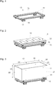
- FIG. 1 shows a transport device 13, with which a printing platform 3 (see for example Fig. 2 ) in the device 1 (see for example Figure 4 ) and can be removed again after completion of the printing operation of the device 1.
- the transport device 13 comprises a frame 16 on which rolling bodies 17, preferably in the form of wheels, for supporting the transport device 13 are arranged on a substrate.
- the transport device 13 is supported by four such rolling elements 17.
- the rolling elements 17 can each be driven by means of an electric motor 18.
- the rolling elements 17 are arranged in the operating position of the transport device 13 on the underside of the frame 16.
- the frame 16 is formed as a rectangular frame with a central opening and made substantially of steel. In the region of the four corners of the frame 16, projections 14 are formed. These serve to secure against displacement storage of the printing platform 3 on the transport device 13. For this purpose, the projections 14 engage in corresponding recesses 15, which are formed in arranged on the underside of the printing platform 3 feet, a.
- FIG. 2 shows the transport device 13 with a printing platform arranged thereon 3.
- the printing platform 3 has a support structure 32, on which a in use position horizontally aligned flat plate 33, which may also be segmented, is arranged.
- the printing platform 3 is also essentially made of steel.
- the transport device 13 and the printing platform 3 are statically constructed so that there is no torsion or deflection in the frame construction.
- the printing platform 3 can be positioned by means of a lifting device, for example in the form of a forklift, on the transport device 13 and removed therefrom again and fed, for example, to a further station such as an unpacking system, a dryer area or a storage area.
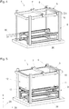
- FIG. 3 shows the arrangement of the transport device 13 and the printing platform 3 according to FIG. 2 in combination with a restriction device 12 for lateral confinement of particulate matter.
- the limiting device 12 is essentially formed of four walls 19, 20, 21 and 22 arranged at right angles to one another. These walls 19, 20, 21 and 22 represent the side walls of an imaginary parallelepiped body.
- the walls 19, 20, 21 and 22 of the limiting device 12 essentially consist of aluminum hollow profiles and are thus made of a lighter material than the printing platform 3 and the transport device 13 built up.
- the walls 19, 20, 21 and 22 are formed rigid, so that there is no deformation when 12 particulate material 4 is arranged in the course of printing on the printing platform 3 and in the interior of the limiting device.
- the walls 19, 20, 21 and 22 at least on its inner surface on a smooth surface with a low coefficient of friction, whereby adhesion of the particulate material 4 can be avoided. This means that the walls 19, 20, 21 and 22 can be moved relative to the particulate material 4, without there being any appreciable change in the spatial position of the adjacent particulate material 4.
- the limiting device 12 has a height 23 of 1.5 m, a width 24 of 4 m and a depth 25 of 2 m. This results in a pressure volume of 12 m 3 . If necessary, the dimensions of the limiting device 12 can also be adapted to larger or smaller pressure volumes.
- a coupling device 10, 11 is provided, with which the limiting device 12 with the Print platform 3 is releasably coupled.
- the coupling device is formed from four locking pins 10, which engage in corresponding recesses 11, wherein these corresponding recesses 11 are arranged both in the limiting device 12 and in the printing platform 3.
- recesses 11 are used, which are formed in the use position in the lower region of the limiting device 12.
- FIG. 4 now shows a preferred embodiment of an apparatus 1 for producing at least one three-dimensional component for the construction industry.
- the device 1 comprises a frame 8, which is essentially formed of four aligned in the vertical direction 9 post.
- a pressure frame 5 in the operating position of the device 1 in the vertical direction 9 is adjustably mounted.
- a print head 7 for dispensing at least one binder at locally predetermined areas and a coating device 6 arranged adjacent thereto for the layered application of particulate material are movably mounted.
- the device 1 furthermore has a supporting device 26.
- the support device 26 comprises two spaced apart rails, on those in FIG. 3 shown arrangement of transport device 13, printing platform 3 and limiting device 12 is positionable. In order to be able to convey this arrangement into the device, subsequent rails 30 (in FIG FIG. 4 indicated by dashed lines) may be provided.
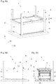
- FIG. 5 shows the device 1 according to FIG. 4 with positioned in the device 1 arrangement of transport device 13, printing platform 3 and limiting device 12 according to FIG. 3 ,
- the limiting device 12 is releasably coupled to the pressure frame 5 by locking bolts 10 are pushed into the recesses 11 arranged in the upper region of the limiting device 12. Simultaneously or subsequently, the coupling between the limiting device 12 and the printing platform 3 is canceled.
- the printing frame 5 and thus the limiting device 12 coupled thereto is lowered, to the extent that the print head 7 and the coating device 6 are located directly above the printing platform 3 and can be started with the printing operation.
- the arrangement of the support device 26, the printing platform 3 and the transport device 13 has an overall height 27, which at least the height 23 of the limiting device 12 (see FIG. 3 ) corresponds. Additionally or alternatively, it can also be provided that a recess for receiving the lowered limiting device 12 is formed in the ground.
- a particulate material 4 is applied in layers by means of the coating device 6 and this by means of at least one binder and optionally one Hardened solidified at locally predetermined areas and interconnected.
- the at least one binder is sprayed with the help of the print head 7 at the locally predetermined areas.
- the printing frame 5 is lifted in the vertical direction 9 by a certain distance 34.
- This path 34 defines the thickness of the subsequently applied layer. Since the limiting device 12 is coupled to the pressure frame 5, the limiting device 12 is forcibly moved by the same path 34 in the vertical direction 9.
- FIGS. 6a, 6b and 6c show the state of the device 1 immediately after the beginning of the printing operation. In this case, a few layers of the particulate material 4 have already been applied and solidified at locally predetermined areas and connected together.
- the locally predetermined areas are approached by the print head 7 based on computer data.
- FIGS. 7a-7c show the device 1 after completion of printing. Schematically indicated is a manufactured three-dimensional component 2, which consists in the hatched area of solidified and interconnected particulate material. The three-dimensional component 2 is surrounded by unconsolidated loose particulate material 4.
- the coupling between the limiting device 12 and the printing platform 3 is restored.
- the coupling between the limiting device 12 and the printing frame 5 is canceled.
- the printing frame 5 is moved one piece up, so that the arrangement of the transport device 13, the printing platform 3 and the Clamping device 12 can be moved out of the device 1, without the limiting device 12 collides with the pressure frame 5.
- At least the printing platform 3 together with the limiting device 12 and the printed interior is subsequently fed to at least one unpacking station. There, the coupling between the limiting device 12 and the printing platform 3 is released and the limiting device 12 in the vertical direction moved up or down. In this case, a large part of the loose particulate material 4 will automatically fall off the printing platform 3. What remains is the manufactured three-dimensional component 2 for the construction industry.
Abstract
Description
- Die Erfindung betrifft eine Vorrichtung zur Herstellung wenigstens eines dreidimensionalen Bauteils für die Bauindustrie aus einer Mehrzahl von auf einer Druckplattform übereinander angeordneter Schichten aus Partikelmaterial, die in örtlich vorbestimmten Bereichen verfestigt und miteinander zum wenigstens einen dreidimensionalen Bauteil verbunden sind, umfassend wenigstens einen Druckrahmen, an welchem wenigstens eine Beschichtungsvorrichtung zur schichtweisen Auftragung des Partikelmaterials auf der Druckplattform und wenigstens ein Druckkopf zur Abgabe wenigstens eines Bindemittels an den örtlich vorbestimmten Bereichen verfahrbar gelagert sind, und ein Gestell, an welchem der Druckrahmen in Gebrauchslage der Vorrichtung zumindest in vertikaler Richtung verstellbar gelagert ist. Die Erfindung betrifft weiterhin ein Verfahren zum Betrieb einer solchen Vorrichtung.
- Die gegenständliche Erfindung betrifft das technische Gebiet des 3D-Drucks in der Bauindustrie. Diesbezüglich werden im Wesentlichen drei Prozesstypen voneinander unterschieden, wobei zwei dieser Prozesstypen, nämlich das "Contour Crafting" und das "Concrete Printing" sehr verwandt sind und Prozesse definieren, in denen ein viskoses Betongemisch durch Düsen in situ verspritzt wird und selbst aushärtet.
- Daneben unterscheidet man als dritten Prozesstyp 3D-Druck-Verfahren auf Basis pulverförmiger Werkstoffe, die unter dem Einfluss zumindest eines Binders zu einem dreidimensionalen Bauteil verbunden werden. Zumeist wird hierzu ein Partikelmaterial schichtweise aufgetragen und in örtlich vorbestimmten Bereichen durch Abgabe wenigstens eines Bindemittels verfestigt und miteinander verbunden.
- Dieses Verfahren kommt auf anderen technischen Gebieten bereits seit längerer Zeit zum Einsatz, wobei die Druckplattform in der Regel während des Druckprozesses nach unten verfahren wird bis der Druckprozess abgeschlossen ist. Zur seitlichen Begrenzung des schichtweise aufgetragenen Partikelmaterials werden beispielsweise Seitenwände abgerollt, wie dies in der
DE 10 2013 018 031 A1 beschrieben ist. Diese Lösung eignet sich aber nicht zur Herstellung dreidimensionaler Bauteile für die Bauindustrie, da man es hier mit sehr viel größeren Dimensionen und Gewichten zu tun hat. Die bedruckte Druckplattform weist beispielsweise bei der Herstellung dreidimensionaler Bauteile für die Bauindustrie mehrere Tonnen Gewicht auf. Gleichzeitig besteht der Wunsch, sehr dünne Schichten aus Partikelmaterial, vorzugsweise in der Größenordnung von 1-2 mm, aufzutragen. Mit dieser Präzision müsste also die Druckplattform abgesenkt werden, was aufgrund des enormen Gewichts kaum möglich ist. - Nun könnte man sich überlegen, die Druckplattform während des Druckprozesses nicht zu bewegen und stattdessen den Druckrahmen zu verfahren. Hierzu gibt es auf anderen technischen Gebieten bereits ebenfalls Lösungen. Beispielsweise beschreibt die
EP 1 872 928 A1 eine Lösung, bei welcher die Druckplattform unbeweglich ist und Seitenwände zur seitlichen Begrenzung des Partikelmaterials in dem Partikelmaterial mitgedruckt werden. Aber auch diese Lösung eignet sich nicht zur Herstellung dreidimensionaler Bauteile für die Bauindustrie, da die solchermaßen hergestellten Seitenwände aufgrund des angesprochenen großen Druckvolumens eine sehr große Materialmenge beanspruchen. Dies ist problematisch, da nach erfolgtem Druck die Seitenwände entsorgt werden müssten, das heißt dass der Materialverlust aufgrund der Ausbildung der Seitenwände sehr hoch wäre, was in weiterer Folge mit hohen Kosten verbunden wäre. - Die Aufgabe der vorliegenden Erfindung besteht also darin, eine gegenüber dem Stand der Technik verbesserte Vorrichtung gemäß dem Oberbegriff des Anspruchs 1 bzw. ein Verfahren zum Betrieb einer solchen Vorrichtung anzugeben, wobei bei dieser Vorrichtung die genannten Nachteile vermieden werden, und welche Vorrichtung es insbesondere ermöglicht, die Druckplattform während des Druckvorgangs feststehend zu belassen und gleichzeitig eine kostengünstige und praktikable Lösung zur seitlichen Begrenzung des Partikelmaterials vorzusehen.
- Diese Aufgabe wird gelöst durch die Merkmale der unabhängigen Ansprüche 1 bzw. 12.
- Es ist also bei der Vorrichtung zur Herstellung wenigstens eines dreidimensionalen Bauteils für die Bauindustrie vorgesehen, dass eine Koppelungsvorrichtung vorgesehen ist, mit welcher eine Begrenzungsvorrichtung zur seitlichen Begrenzung des Partikelmaterials mit dem wenigstens einen Druckrahmen lösbar koppelbar ist, so dass die Begrenzungsvorrichtung mit dem Druckrahmen bei einer Verstellung zumindest in die vertikale Richtung mitbewegbar ist.
- Auf diese Weise ist es möglich, eine wiederverwendbare Begrenzungsvorrichtung zur seitlichen Begrenzung des Partikelmaterials während des Druckvorgangs mit dem wenigstens einen Druckrahmen zu koppeln und den Druckrahmen gegenüber einer während des Druckprozesses feststehenden Druckplattform in vertikaler Richtung zu verstellen und dabei gleichzeitig eine optimale seitliche Begrenzung des Partikelmaterials sicherzustellen.
- Ein großer Vorteil besteht darin, dass die Druckplattform samt der Begrenzungsvorrichtung und dem wenigstens einen hergestellten dreidimensionalen Bauteil von dem Druckrahmen entfernt und zu einem Entformungsbereich transportiert werden kann, an welchem die Entformung des wenigstens einen hergestellten dreidimensionalen Bauteils erfolgt. Bei der Entformung entweicht loses Material, welches nicht Teil des Bauteils ist. Dabei kann es zu einer ungünstigen Staubentwicklung gelangen. Würde man die Entformung unmittelbar im Bereich des Druckrahmens durchführen, so bestünde die Gefahr, dass das lose Material Bestandteile des Druckrahmens, wie z.B. den Antrieb des Druckkopfes, beschädigt. Diese Gefahr ist gänzlich gebannt, wenn die Entformung an einem separaten Ort erfolgt.
- Weiterhin würde der Druckrahmen die Zugänglichkeit zu dem wenigstens einen hergestellten dreidimensionalen Bauteil erschweren. Auch dieser Nachteil kann durch die vorliegende Erfindung behoben werden.
- Und schließlich bietet die Entformung an einem vom Druckrahmen separaten Ort die Möglichkeit, die Herstellung zu beschleunigen, da unmittelbar nach dem Abtransport des Pakets aus Druckplattform samt der Begrenzungsvorrichtung und dem wenigstens einen hergestellten dreidimensionalen Bauteil bereits mit dem Druck eines weiteren Bauteils auf einer neuen Druckplattform begonnen werden kann, ohne dass die Entformung abgewartet werden muss.
- Bei dem erfindungsgemäßen Verfahren zum Betrieb der erfindungsgemäßen Vorrichtung ist es vorgesehen, dass
- eine Begrenzungsvorrichtung zur seitlichen Begrenzung des Partikelmaterials mittels der hierzu vorgesehenen Koppelungsvorrichtung mit dem wenigstens einen Druckrahmen gekoppelt wird,
- der Druckrahmen samt der daran gekoppelten Begrenzungsvorrichtung auf Höhe der Druckplattform positioniert wird, und
- der Druckvorgang zur Herstellung des wenigstens eines dreidimensionalen Bauteils für die Bauindustrie durch schichtweise Auftragung des Partikelmaterials und Abgabe des wenigstens einen Bindemittels in den örtlich vorbestimmten Bereichen durchgeführt wird, wobei der Druckrahmen zumindest in die vertikale Richtung schrittweise mit einer Schrittweite, welche im Wesentlichen der Höhe der aufgetragenen Partikelmaterialschichten entspricht, angehoben wird.
- Besonders vorteilhafte Ausführungsformen der erfindungsgemäßen Vorrichtung bzw. des erfindungsgemäßen Verfahren zum Betrieb der erfindungsgemäßen Vorrichtung sind in den abhängigen Ansprüchen 2-11 und 13-15 definiert.
- Es ist gemäß einer bevorzugten Ausführungsform vorgesehen, dass die Koppelungsvorrichtung, mit welcher eine Begrenzungsvorrichtung zur seitlichen Begrenzung des Partikelmaterials mit dem wenigstens einen Druckrahmen lösbar koppelbar ist, und gegebenenfalls die Koppelungsvorrichtung, mit welcher die Begrenzungsvorrichtung zur seitlichen Begrenzung des Partikelmaterials mit der Druckplattform und/oder einer gegebenenfalls vorhandenen Transportvorrichtung lösbar koppelbar ist, wenigstens einen, vorzugsweise vier, Verriegelungsbolzen und korrespondierende Ausnehmungen umfasst.
- Diese Koppelungsvorrichtungen können aber auch auf eine andere Art technisch realisiert werden. Es können beispielsweise auch lösbare Schnapp- und/oder Rastverbindungen zum Einsatz kommen. Weiterhin ist es denkbar, dass anstelle einer rein mechanischen Lösung eine elektromechanische Lösung, die auch mit einer Steuerungseinheit verbunden sein kann, zum Einsatz kommt.
- Weitere Einzelheiten und Vorteile der Erfindung werden anhand der Figurenbeschreibung unter Bezugnahme auf die Zeichnungen im Folgenden näher erläutert. Darin zeigen:
- Fig. 1
- eine Transportvorrichtung in einer perspektivischen Ansicht,
- Fig. 2
- die Transportvorrichtung aus der
Figur 1 mit einer darauf angeordneten Druckplattform, - Fig. 3
- die Anordnung aus einer Transportvorrichtung und einer Druckplattform gemäß
Fig. 2 in Kombination mit einer Begrenzungsvorrichtung zur seitlichen Begrenzung des Partikelmaterials, - Fig. 4
- eine Vorrichtung zur Herstellung wenigstens eines dreidimensionalen Bauteils für die Bauindustrie gemäß einer bevorzugten Ausführungsform,
- Fig.5
- die Vorrichtung gemäß
Fig. 4 mit einer darin angeordneten Transportvorrichtung, einer Druckplattform und einer Begrenzungsvorrichtung, - Fig. 6a-6c
- die Anordnung gemäß
Fig. 5 zu Beginn des Druckvorgangs und zwar in einer perspektivischen Ansicht (Fig. 6a ), in einer Seitenansicht (Fig. 6b ) und in einer Querschnittsansicht entlang der in derFig. 6b eingezeichneten Schnittebene 31 (Fig. 6c ) und - Fig. 7a-7c
- die Anordnung gemäß den
Figuren 6a-6c nach Abschluss des Druckvorgangs. -
Figur 1 zeigt eine Transportvorrichtung 13, mit welcher eine Druckplattform 3 (vergleiche beispielsweiseFig. 2 ) in der Vorrichtung 1 (vergleiche beispielsweiseFig.4 ) positioniert und nach Abschluss des Druckvorgangs der Vorrichtung 1 wieder entnommen werden kann. Die Transportvorrichtung 13 umfasst einen Rahmen 16, an welchem Wälzkörper 17, vorzugsweise in Form von Laufrädern, zur Abstützung der Transportvorrichtung 13 an einem Untergrund angeordnet sind. Im vorliegenden Fall ist die Transportvorrichtung 13 über vier solche Wälzkörper 17 abgestützt. Je nach Größe der Druckplattform 3 können beispielsweise auch sechs oder mehr Wälzkörper 17 verwendet werden. Die Wälzkörper 17 sind jeweils mittels eines Elektromotors 18 antreibbar. Die Wälzkörper 17 sind in Gebrauchslage der Transportvorrichtung 13 an der Unterseite des Rahmens 16 angeordnet. - Der Rahmen 16 ist als rechteckiger Rahmen mit einer zentralen Öffnung ausgebildet und im Wesentlichen aus Stahl gefertigt. Im Bereich der vier Ecken des Rahmens 16 sind Vorsprünge 14 ausgebildet. Diese dienen zur verschiebesicheren Lagerung der Druckplattform 3 auf der Transportvorrichtung 13. Dazu greifen die Vorsprünge 14 in korrespondierende Ausnehmungen 15, welche in auf der Unterseite der Druckplattform 3 angeordnete Füße ausgebildet sind, ein.
-
Figur 2 zeigt die Transportvorrichtung 13 mit einer darauf angeordneten Druckplattform 3. Die Druckplattform 3 weist eine Trägerstruktur 32 auf, auf welcher eine in Gebrauchslage horizontal ausgerichtete ebene Platte 33, welche auch segmentiert sein kann, angeordnet ist. Die Druckplattform 3 ist ebenfalls im Wesentlichen aus Stahl gefertigt. Die Transportvorrichtung 13 und die Druckplattform 3 werden statisch so konstruiert, dass sich keine Torsion bzw. Durchbiegung in der Rahmenkonstruktion ergeben. Die Druckplattform 3 kann mittels einer Hebevorrichtung beispielsweise in Form eines Gabelstaplers auf der Transportvorrichtung 13 positionieren und von dieser wieder entfernt und beispielsweise einer weiteren Station wie einer Entpackungsanlage, einem Trocknerbereich oder einem Abstellbereich zugeführt werden. -
Figur 3 zeigt die Anordnung aus der Transportvorrichtung 13 und der Druckplattform 3 gemäßFigur 2 in Kombination mit einer Begrenzungsvorrichtung 12 zur seitlichen Begrenzung von Partikelmaterial. Die Begrenzungsvorrichtung 12 ist im Wesentlichen aus vier rechtwinklig zueinander angeordneten Wänden 19, 20, 21 und 22 gebildet. Diese Wände 19,20, 21 und 22 stellen die Seitenwände eines gedachten quaderförmigen Körpers dar. Die Wände 19, 20, 21 und 22 der Begrenzungsvorrichtung 12 bestehen im Wesentlichen aus Aluminiumhohlprofilen und sind damit aus einem leichteren Material als die Druckplattform 3 und die Transportvorrichtung 13 aufgebaut. Die Wände 19, 20, 21 und 22 sind biegesteif ausgebildet, sodass es zu keiner Verformung kommt, wenn im Zuge des Druckvorgangs auf der Druckplattform 3 und in dem Innenraum der Begrenzungsvorrichtung 12 Partikelmaterial 4 angeordnet wird. Darüber hinaus weisen die Wände 19, 20, 21 und 22 zumindest auf ihrer Innenfläche eine glatte Oberfläche mit einem niedrigen Reibungskoeffizienten auf, wodurch ein Anhaften des Partikelmaterials 4 vermieden werden kann. Das bedeutet, dass die Wände 19, 20, 21 und 22 relativ zu dem Partikelmaterial 4 bewegt werden können, ohne dass es dabei zu einer nennenswerten Änderung der räumlichen Lage des benachbarten Partikelmaterials 4 kommt. - Die Begrenzungsvorrichtung 12 weist eine Höhe 23 von 1,5 m, eine Breite 24 von 4 m und eine Tiefe 25 von 2 m auf. Damit ergibt sich ein Druckvolumen von 12 m3. Im Bedarfsfall können die Dimensionen der Begrenzungsvorrichtung 12 auch an größere oder kleinere Druckvolumina angepasst werden.
- Um die Anordnung aus der Transportvorrichtung 13, der Druckplattform 3 und der Begrenzungsvorrichtung 12 in ihrer Gesamtheit bewegen zu können, ohne dass es dabei zu einer Relativbewegung dieser drei Komponenten untereinander kommt, ist eine Kopplungsvorrichtung 10, 11 vorgesehen, mit welcher die Begrenzungsvorrichtung 12 mit der Druckplattform 3 lösbar koppelbar ist. Konkret wird die Kopplungsvorrichtung gebildet aus vier Verriegelungsbolzen 10, welche in korrespondierenden Ausnehmungen 11 eingreifen, wobei diese korrespondierenden Ausnehmungen 11 sowohl in der Begrenzungsvorrichtung 12 als auch in der Druckplattform 3 angeordnet sind. Zur lösbaren Kopplung der Begrenzungsvorrichtung 12 mit der Druckplattform 3 werden Ausnehmungen 11 verwendet, die in Gebrauchslage im unteren Bereich der Begrenzungsvorrichtung 12 ausgebildet sind. Auf den Zweck der im oberen Bereich der Begrenzungsvorrichtung 12 angeordneten Ausnehmungen 11 wird nachfolgend eingegangen.
-
Figur 4 zeigt nun eine bevorzugte Ausführungsform einer Vorrichtung 1 zur Herstellung wenigstens eines dreidimensionalen Bauteils für die Bauindustrie. Die Vorrichtung 1 weist ein Gestell 8 auf, welches im Wesentlichen gebildet wird aus vier in vertikaler Richtung 9 ausgerichteten Pfosten. An dem Gestell 8 ist ein Druckrahmen 5 in Gebrauchslage der Vorrichtung 1 in vertikaler Richtung 9 verstellbar gelagert. An dem Druckrahmen 5 sind ein Druckkopf 7 zur Abgabe wenigstens eines Bindemittels an örtlich vorbestimmten Bereichen sowie eine benachbart dazu angeordnete Beschichtungsvorrichtunge 6 zur schichtweisen Auftragung von Partikelmaterial verfahrbar gelagert. - Die Vorrichtung 1 weist weiterhin eine Abstützvorrichtung 26 auf. Die Abstützvorrichtung 26 umfasst zwei voneinander beabstandete Schienen, auf denen die in
Figur 3 gezeigte Anordnung aus Transportvorrichtung 13, Druckplattform 3 und Begrenzungsvorrichtung 12 positionierbar ist. Um diese Anordnung in die Vorrichtung hineinbefördern zu können, können anschließende Schienen 30 (in derFigur 4 mit gestrichelten Linien angedeutet) vorgesehen sein. -
Figur 5 zeigt die Vorrichtung 1 gemäßFigur 4 mit in der Vorrichtung 1 positionierter Anordnung aus Transportvorrichtung 13, Druckplattform 3 und Begrenzungsvorrichtung 12 gemäßFigur 3 . Zur Vorbereitung des Druckvorgangs wird die Begrenzungsvorrichtung 12 mit dem Druckrahmen 5 lösbar gekoppelt, indem Verriegelungsbolzen 10 in die im oberen Bereich der Begrenzungsvorrichtung 12 angeordnete Ausnehmungen 11 hineingeschoben werden. Gleichzeitig oder daran anschließend wird die Kopplung zwischen der Begrenzungsvorrichtung 12 und der Druckplattform 3 aufgehoben. - In weiterer Folge wird der Druckrahmen 5 und damit die daran gekoppelte Begrenzungsvorrichtung 12 abgesenkt und zwar so weit, dass sich der Druckkopf 7 und die Beschichtungsvorrichtunge 6 unmittelbar über der Druckplattform 3 befinden und mit dem Druckvorgang begonnen werden kann. Es bietet sich dabei an, dass die Anordnung aus der Abstützvorrichtung 26, der Druckplattform 3 und der Transportvorrichtung 13 eine Gesamthöhe 27 aufweist, welche mindestens der Höhe 23 der Begrenzungsvorrichtung 12 (vergleiche
Figur 3 ) entspricht. Ergänzend oder alternativ dazu kann es auch vorgesehen sein, dass im Untergrund eine Ausnehmung zur Aufnahme der abgesenkten Begrenzungsvorrichtung 12 ausgebildet ist. - Es sei noch darauf hingewiesen, dass die x- und y-Komponenten, welche die horizontale Ebene definieren, mit den Bezugszeichen 28 und 29 versehen sind.
- Es wird nun mit dem Druckvorgang begonnen. Dabei wird mittels der Beschichtungsvorrichtunge 6 schichtweise ein Partikelmaterial 4 aufgetragen und dieses mittels wenigstens eines Bindemittels und gegebenenfalls eines Härtemittels an örtlich vorbestimmten Bereichen verfestigt und miteinander verbunden. Das wenigstens eine Bindemittel wird dabei mit Hilfe des Druckkopfs 7 an den örtlich vorbestimmten Bereichen versprüht. Nachdem auf diese Weise eine Schicht mit einer bestimmten Schichtdicke aufgetragen und bearbeitet wurde, wird der Druckrahmen 5 in vertikaler Richtung 9 um einen bestimmten Weg 34 angehoben. Dieser Weg 34 definiert die Dicke der nachfolgend aufgetragenen Schicht. Da die Begrenzungsvorrichtung 12 mit dem Druckrahmen 5 gekoppelt ist, wird die Begrenzungsvorrichtung 12 zwangsweise um denselben Weg 34 in vertikaler Richtung 9 mitbewegt. Diese Vorgänge wiederholen sich so lange, bis das gesamte zur Verfügung stehende Druckvolumen ausgereizt ist bzw. bis das wenigstens eine herzustellende dreidimensionale Bauteil fertig gestellt ist.
- Die
Figuren 6a, 6b und 6c zeigen den Zustand der Vorrichtung 1 unmittelbar nach Beginn des Druckvorgangs. Dabei wurden bereits einige wenige Schichten des Partikelmaterials 4 aufgetragen und an örtlich vorbestimmten Bereichen verfestigt und miteinander verbunden. - Die örtlich vorbestimmten Bereiche werden basierend auf Computerdaten von dem Druckkopf 7 angefahren.
- Die
Figuren 7a-7c zeigen die Vorrichtung 1 nach abgeschlossenem Druckvorgang. Schematisch angedeutet ist ein hergestelltes dreidimensionales Bauteil 2, welches im schraffierten Bereich aus verfestigtem und miteinander verbundenem Partikelmaterial besteht. Das dreidimensionale Bauteil 2 wird von nicht verfestigtem losem Partikelmaterial 4 umgeben. - Zur Ausformung des dreidimensionalen Bauteils 2 wird die Kopplung zwischen der Begrenzungsvorrichtung 12 und der Druckplattform 3 wieder hergestellt. Die Kopplung zwischen der Begrenzungsvorrichtung 12 und dem Druckrahmen 5 wird aufgehoben. Der Druckrahmen 5 wird ein Stück nach oben bewegt, sodass die Anordnung aus der Transportvorrichtung 13, der Druckplattform 3 und der Begrenzungsvorrichtung 12 aus der Vorrichtung 1 herausgefahren werden kann, ohne dass die Begrenzungsvorrichtung 12 mit dem Druckrahmen 5 kollidiert.
- Zumindest die Druckplattform 3 zusammen mit der Begrenzungsvorrichtung 12 und dem gedruckten Innenleben wird in weiterer Folge zumindest einer Entpackungsstation zugeführt. Dort wird die Kopplung zwischen der Begrenzungsvorrichtung 12 und der Druckplattform 3 aufgehoben und die Begrenzungsvorrichtung 12 in vertikaler Richtung nach oben oder unten verfahren. Dabei wird ein großer Teil des losen Partikelmaterials 4 von selbst von der Druckplattform 3 herabfallen. Übrig bleibt das hergestellte dreidimensionale Bauteil 2 für die Bauindustrie.
Claims (15)
- Vorrichtung (1) zur Herstellung wenigstens eines dreidimensionalen Bauteils (2) für die Bauindustrie aus einer Mehrzahl von auf einer Druckplattform (3) übereinander angeordneter Schichten aus Partikelmaterial (4), die in örtlich vorbestimmten Bereichen verfestigt und miteinander zum wenigstens einen dreidimensionalen Bauteil (2) verbunden sind, umfassend wenigstens einen Druckrahmen (5), an welchem wenigstens eine Beschichtungsvorrichtung (6) zur schichtweisen Auftragung des Partikelmaterials (4) auf der Druckplattform (3) und wenigstens ein Druckkopf (7) zur Abgabe wenigstens eines Bindemittels an den örtlich vorbestimmten Bereichen verfahrbar gelagert sind, und ein Gestell (8), an welchem der Druckrahmen (5) in Gebrauchslage der Vorrichtung (1) zumindest in vertikaler Richtung (9) verstellbar gelagert ist, dadurch gekennzeichnet, dass eine Koppelungsvorrichtung (10, 11) vorgesehen ist, mit welcher eine Begrenzungsvorrichtung (12) zur seitlichen Begrenzung des Partikelmaterials (4) mit dem wenigstens einen Druckrahmen (5) lösbar koppelbar ist, so dass die Begrenzungsvorrichtung (12) mit dem Druckrahmen (5) bei einer Verstellung zumindest in die vertikale Richtung (9) mitbewegbar ist.
- Vorrichtung (1) nach Anspruch 1, wobei eine Transportvorrichtung (13) vorgesehen ist, auf welcher die Druckplattform (3) angeordnet ist, vorzugsweise wobei die Druckplattform (3) über Vorsprünge (14) und korrespondierende Ausnehmungen (15) auf der Transportvorrichtung (13) verschiebesicher gelagert ist.
- Vorrichtung (1) nach Anspruch 2, wobei die Transportvorrichtung (13) im Wesentlichen aus einem Rahmen (16) gebildet ist, an welchem Wälzkörper (17) zur Abstützung der Transportvorrichtung (13) an einem Untergrund angeordnet sind.
- Vorrichtung (1) nach Anspruch 3, wobei die Wälzkörper (17), vorzugsweise mittels Elektromotoren (18), antreibbar sind.
- Vorrichtung (1) nach einem der Ansprüche 1 bis 4, wobei eine weitere Koppelungsvorrichtung (10, 11) vorgesehen ist, mit welcher die Begrenzungsvorrichtung (12) zur seitlichen Begrenzung des Partikelmaterials (4) mit der Druckplattform (3) und/oder einer gegebenenfalls vorhandenen Transportvorrichtung (13) lösbar koppelbar ist.
- Vorrichtung (1) nach einem der Ansprüche 1 bis 5, wobei die Begrenzungsvorrichtung (12) im Wesentlichen aus vier rechtwinklig zueinander angeordneten Wänden (19, 20, 21, 22) gebildet ist.
- Vorrichtung (1) nach Anspruch 6, wobei die Wände (19, 20, 21, 22) der Begrenzungsvorrichtung (12)- im Wesentlichen aus Hohlprofilen, vorzugsweise aus Aluminium, bestehen, und/oder- biegesteif ausgebildet sind, und/oder- eine glatte Oberfläche mit einem niedrigen Reibungskoeffizienten aufweisen, um ein Anhaften des Partikelmaterials (4) zu vermeiden.
- Vorrichtung (1) nach einem der Ansprüche 1 bis 7, wobei die Begrenzungsvorrichtung (12)- eine Höhe (23) von 1 bis 2 m, vorzugsweise 1,5 m, und/oder- eine Breite (24) von 3 bis 5 m, vorzugsweise 4 m, und/oder- eine Tiefe (25) von 1 bis 3 m, vorzugsweise 2 m,aufweist.
- Vorrichtung (1) nach einem der Ansprüche 1 bis 8, wobei eine, vorzugsweise schienenförmige, Abstützvorrichtung (26) zur Abstützung der Druckplattform (3) und einer gegebenenfalls vorhandenen Transportvorrichtung (13) vorgesehen ist.
- Vorrichtung (1) nach Anspruch 9, wobei die Anordnung aus der Abstützvorrichtung (26), der Druckplattform (3) und einer gegebenenfalls vorhandenen Transportvorrichtung (13) eine Gesamthöhe (27) aufweist, welche mindestens der Höhe (23) der Begrenzungsvorrichtung (12) entspricht.
- Vorrichtung (1) nach einem der Ansprüche 1 bis 10, wobei die Koppelungsvorrichtung (10, 11), mit welcher eine Begrenzungsvorrichtung (12) zur seitlichen Begrenzung des Partikelmaterials (4) mit dem wenigstens einen Druckrahmen (5) lösbar koppelbar ist, und gegebenenfalls die Koppelungsvorrichtung (10, 11), mit welcher die Begrenzungsvorrichtung (12) zur seitlichen Begrenzung des Partikelmaterials (4) mit der Druckplattform (3) und/oder einer gegebenenfalls vorhandenen Transportvorrichtung (13) lösbar koppelbar ist, wenigstens einen, vorzugsweise vier, Verriegelungsbolzen (10) und korrespondierende Ausnehmungen (11) umfasst.
- Verfahren zum Betrieb einer Vorrichtung (1) nach einem der Ansprüche 1 bis 11, dadurch gekennzeichnet, dass- eine Begrenzungsvorrichtung (12) zur seitlichen Begrenzung des Partikelmaterials (4) mittels der hierzu vorgesehenen Koppelungsvorrichtung (10, 11) mit dem wenigstens einen Druckrahmen (5) gekoppelt wird,- der Druckrahmen (5) samt der daran gekoppelten Begrenzungsvorrichtung (12) auf Höhe der Druckplattform (3) positioniert wird, und- der Druckvorgang zur Herstellung des wenigstens eines dreidimensionalen Bauteils (2) für die Bauindustrie durch schichtweise Auftragung des Partikelmaterials (4) und Abgabe des wenigstens einen Bindemittels in den örtlich vorbestimmten Bereichen durchgeführt wird, wobei der Druckrahmen (5) zumindest in die vertikale Richtung (9) schrittweise mit einer Schrittweite, welche im Wesentlichen der Höhe der aufgetragenen Partikelmaterialschichten entspricht, angehoben wird.
- Verfahren nach Anspruch 12, wobei die Begrenzungsvorrichtung (12) nach Abschluss des Druckvorgangs vom wenigstens einen Druckrahmen (5) entkoppelt wird.
- Verfahren nach Anspruch 12 oder 13, wobei die Druckplattform (3) und die Begrenzungsvorrichtung (12) zu Beginn des Verfahrens in der Vorrichtung (1) positioniert und nach Abschluss des Druckvorgangs der Vorrichtung (1) wieder entnommen werden.
- Verfahren nach einem der Ansprüche 1 bis 14, wobei die Begrenzungsvorrichtung (12) zu Beginn des Verfahrens mittels der hierzu vorgesehenen Koppelungsvorrichtung (10, 11) mit der Druckplattform (3) und/oder einer gegebenenfalls vorhandenen Transportvorrichtung (13) gekoppelt ist und diese Koppelung aufgehoben wird.
Priority Applications (1)
| Application Number | Priority Date | Filing Date | Title |
|---|---|---|---|
| PL17177714T PL3260272T3 (pl) | 2016-06-23 | 2017-06-23 | Urządzenie do wytwarzania co najmniej jednego trójwymiarowego elementu dla przemysłu budowlanego |
Applications Claiming Priority (1)
| Application Number | Priority Date | Filing Date | Title |
|---|---|---|---|
| ATA50569/2016A AT518837B1 (de) | 2016-06-23 | 2016-06-23 | Vorrichtung zur Herstellung wenigstens eines dreidimensionalen Bauteils für die Bauindustrie |
Publications (2)
| Publication Number | Publication Date |
|---|---|
| EP3260272A1 true EP3260272A1 (de) | 2017-12-27 |
| EP3260272B1 EP3260272B1 (de) | 2018-10-17 |
Family
ID=59215617
Family Applications (1)
| Application Number | Title | Priority Date | Filing Date |
|---|---|---|---|
| EP17177714.7A Active EP3260272B1 (de) | 2016-06-23 | 2017-06-23 | Vorrichtung zur herstellung wenigstens eines dreidimensionalen bauteils für die bauindustrie |
Country Status (4)
| Country | Link |
|---|---|
| EP (1) | EP3260272B1 (de) |
| AT (1) | AT518837B1 (de) |
| DK (1) | DK3260272T3 (de) |
| PL (1) | PL3260272T3 (de) |
Cited By (3)
| Publication number | Priority date | Publication date | Assignee | Title |
|---|---|---|---|---|
| CN110406102A (zh) * | 2019-08-27 | 2019-11-05 | 江苏集萃微纳自动化系统与装备技术研究所有限公司 | 一种可拆卸3d打印机的缸体组件 |
| AT522560A4 (de) * | 2019-05-29 | 2020-12-15 | Progress Maschinen & Automation Ag | Anordnung zur Herstellung wenigstens eines dreidimensionalen Bauteils für die Bauindustrie |
| CN112157795A (zh) * | 2020-09-22 | 2021-01-01 | 湖南汇渠建筑科技有限公司 | 一种基于bim的装配式建筑混凝土浇筑装置 |
Families Citing this family (1)
| Publication number | Priority date | Publication date | Assignee | Title |
|---|---|---|---|---|
| DE102019005605A1 (de) | 2019-08-09 | 2021-02-11 | Ing3D Ug | Verfahren zur Herstellung eines additiv gefertigten Produkts aus einem mineralischen Ausgangsmaterial mittels direkter Laserversinterung sowie ein nach diesem Verfahren hergestelltes Leichtbauteil |
Citations (4)
| Publication number | Priority date | Publication date | Assignee | Title |
|---|---|---|---|---|
| WO2005097476A2 (en) * | 2004-04-02 | 2005-10-20 | Z Corporation | Methods and apparatus for 3d printing |
| WO2006100556A2 (en) * | 2005-03-22 | 2006-09-28 | Enrico Dini | Method and device for building automatically conglomerate structures |
| WO2011120505A1 (de) * | 2010-03-31 | 2011-10-06 | Voxeljet Technology Gmbh | Vorrichtung zum herstellen dreidimensionaler modelle |
| WO2015141776A1 (ja) * | 2014-03-19 | 2015-09-24 | シーメット株式会社 | 三次元造形装置の造形タンク |
Family Cites Families (4)
| Publication number | Priority date | Publication date | Assignee | Title |
|---|---|---|---|---|
| JP4238938B2 (ja) * | 2007-05-30 | 2009-03-18 | パナソニック電工株式会社 | 積層造形装置 |
| ITPI20070108A1 (it) * | 2007-09-17 | 2009-03-18 | Enrico Dini | Metodo perfezionato per la realizzazione automatica di strutture di conglomerato |
| JP5355213B2 (ja) * | 2009-05-18 | 2013-11-27 | パナソニック株式会社 | 三次元形状造形物を造形する積層造形装置 |
| US9149870B2 (en) * | 2012-09-14 | 2015-10-06 | Aerojet Rocketdyne Of De, Inc. | Additive manufacturing chamber with reduced load |
-
2016
- 2016-06-23 AT ATA50569/2016A patent/AT518837B1/de active
-
2017
- 2017-06-23 DK DK17177714.7T patent/DK3260272T3/en active
- 2017-06-23 PL PL17177714T patent/PL3260272T3/pl unknown
- 2017-06-23 EP EP17177714.7A patent/EP3260272B1/de active Active
Patent Citations (4)
| Publication number | Priority date | Publication date | Assignee | Title |
|---|---|---|---|---|
| WO2005097476A2 (en) * | 2004-04-02 | 2005-10-20 | Z Corporation | Methods and apparatus for 3d printing |
| WO2006100556A2 (en) * | 2005-03-22 | 2006-09-28 | Enrico Dini | Method and device for building automatically conglomerate structures |
| WO2011120505A1 (de) * | 2010-03-31 | 2011-10-06 | Voxeljet Technology Gmbh | Vorrichtung zum herstellen dreidimensionaler modelle |
| WO2015141776A1 (ja) * | 2014-03-19 | 2015-09-24 | シーメット株式会社 | 三次元造形装置の造形タンク |
Cited By (5)
| Publication number | Priority date | Publication date | Assignee | Title |
|---|---|---|---|---|
| AT522560A4 (de) * | 2019-05-29 | 2020-12-15 | Progress Maschinen & Automation Ag | Anordnung zur Herstellung wenigstens eines dreidimensionalen Bauteils für die Bauindustrie |
| AT522560B1 (de) * | 2019-05-29 | 2020-12-15 | Progress Maschinen & Automation Ag | Anordnung zur Herstellung wenigstens eines dreidimensionalen Bauteils für die Bauindustrie |
| CN110406102A (zh) * | 2019-08-27 | 2019-11-05 | 江苏集萃微纳自动化系统与装备技术研究所有限公司 | 一种可拆卸3d打印机的缸体组件 |
| CN110406102B (zh) * | 2019-08-27 | 2023-09-12 | 江苏集萃微纳自动化系统与装备技术研究所有限公司 | 一种可拆卸3d打印机的缸体组件 |
| CN112157795A (zh) * | 2020-09-22 | 2021-01-01 | 湖南汇渠建筑科技有限公司 | 一种基于bim的装配式建筑混凝土浇筑装置 |
Also Published As
| Publication number | Publication date |
|---|---|
| AT518837A1 (de) | 2018-01-15 |
| EP3260272B1 (de) | 2018-10-17 |
| DK3260272T3 (en) | 2019-02-18 |
| AT518837B1 (de) | 2018-06-15 |
| PL3260272T3 (pl) | 2019-05-31 |
Similar Documents
| Publication | Publication Date | Title |
|---|---|---|
| EP3077181B1 (de) | Baubehälter mit verfahrbaren seitenwänden | |
| EP1563928B1 (de) | Vorrichtung zum schichtweisen Aufbau von Modellen | |
| EP2822753B1 (de) | Verfahren und vorrichtung zum herstellen dreidimensionaler modelle | |
| EP3351384B1 (de) | 3d-drucker, 3d-druckeranordnung und generatives fertigungsverfahren | |
| EP2552674B1 (de) | Vorrichtung zum herstellen dreidimensionaler modelle | |
| EP3260272B1 (de) | Vorrichtung zur herstellung wenigstens eines dreidimensionalen bauteils für die bauindustrie | |
| EP1872928B1 (de) | Verfahren zum Aufbauen eines dreidimensionalen Körpers | |
| EP2391499B1 (de) | Rapid-prototyping-anlage aufweisend eine baubox | |
| DE102013227010A1 (de) | Vorrichtung zum Herstellen eines dreidimensionalen Objekts mit magnetischer Bauunterlagenbefestigung | |
| EP3966019B1 (de) | Baubox-system für einen 3d-drucker, 3d-drucker, 3d-drucker-system, verwendung des baubox-systems und 3d-druck-verfahren | |
| AT522560B1 (de) | Anordnung zur Herstellung wenigstens eines dreidimensionalen Bauteils für die Bauindustrie | |
| WO2019154528A1 (de) | 3d-drucker und generatives fertigungsverfahren | |
| DE1683809C3 (de) | Formpresse zum Herstellen von Platten | |
| WO1983002410A1 (en) | Device for changing model plates in molding machines | |
| DE102022126586A1 (de) | 3D-Druck-Verfahren und 3D-Drucker | |
| DE102017002932A1 (de) | Hebevorrichtung für Bauplattformen in Baubehältern in Schichtbauverfahren | |
| EP0515884A1 (de) | Vorrichtung zur Beschichtung eines Maschinenbetts einer Werkzeugmaschine, insbesondere einer Schleifmaschine | |
| DD251960A1 (de) | Vorrichtung zum zufuehren, stapeln und ueberfuehren von gegenstaenden zwischen foerderern | |
| DE1584443B2 (de) | Fahrbare anlage zur laufenden anfertigung groesserer mauerteile o.dgl. |
Legal Events
| Date | Code | Title | Description |
|---|---|---|---|
| PUAI | Public reference made under article 153(3) epc to a published international application that has entered the european phase |
Free format text: ORIGINAL CODE: 0009012 |
|
| STAA | Information on the status of an ep patent application or granted ep patent |
Free format text: STATUS: THE APPLICATION HAS BEEN PUBLISHED |
|
| AK | Designated contracting states |
Kind code of ref document: A1 Designated state(s): AL AT BE BG CH CY CZ DE DK EE ES FI FR GB GR HR HU IE IS IT LI LT LU LV MC MK MT NL NO PL PT RO RS SE SI SK SM TR |
|
| AX | Request for extension of the european patent |
Extension state: BA ME |
|
| STAA | Information on the status of an ep patent application or granted ep patent |
Free format text: STATUS: REQUEST FOR EXAMINATION WAS MADE |
|
| 17P | Request for examination filed |
Effective date: 20180119 |
|
| RBV | Designated contracting states (corrected) |
Designated state(s): AL AT BE BG CH CY CZ DE DK EE ES FI FR GB GR HR HU IE IS IT LI LT LU LV MC MK MT NL NO PL PT RO RS SE SI SK SM TR |
|
| GRAP | Despatch of communication of intention to grant a patent |
Free format text: ORIGINAL CODE: EPIDOSNIGR1 |
|
| STAA | Information on the status of an ep patent application or granted ep patent |
Free format text: STATUS: GRANT OF PATENT IS INTENDED |
|
| RIC1 | Information provided on ipc code assigned before grant |
Ipc: B29C 64/255 20170101ALI20180221BHEP Ipc: B29C 64/259 20170101ALI20180221BHEP Ipc: B29C 64/165 20170101AFI20180221BHEP |
|
| INTG | Intention to grant announced |
Effective date: 20180321 |
|
| GRAS | Grant fee paid |
Free format text: ORIGINAL CODE: EPIDOSNIGR3 |
|
| GRAA | (expected) grant |
Free format text: ORIGINAL CODE: 0009210 |
|
| STAA | Information on the status of an ep patent application or granted ep patent |
Free format text: STATUS: THE PATENT HAS BEEN GRANTED |
|
| AK | Designated contracting states |
Kind code of ref document: B1 Designated state(s): AL AT BE BG CH CY CZ DE DK EE ES FI FR GB GR HR HU IE IS IT LI LT LU LV MC MK MT NL NO PL PT RO RS SE SI SK SM TR |
|
| REG | Reference to a national code |
Ref country code: GB Ref legal event code: FG4D Free format text: NOT ENGLISH |
|
| REG | Reference to a national code |
Ref country code: CH Ref legal event code: EP |
|
| REG | Reference to a national code |
Ref country code: IE Ref legal event code: FG4D Free format text: LANGUAGE OF EP DOCUMENT: GERMAN |
|
| REG | Reference to a national code |
Ref country code: DE Ref legal event code: R096 Ref document number: 502017000256 Country of ref document: DE Ref country code: AT Ref legal event code: REF Ref document number: 1053473 Country of ref document: AT Kind code of ref document: T Effective date: 20181115 |
|
| REG | Reference to a national code |
Ref country code: CH Ref legal event code: NV Representative=s name: ISLER AND PEDRAZZINI AG, CH |
|
| REG | Reference to a national code |
Ref country code: NL Ref legal event code: FP |
|
| REG | Reference to a national code |
Ref country code: DK Ref legal event code: T3 Effective date: 20190211 |
|
| REG | Reference to a national code |
Ref country code: SE Ref legal event code: TRGR |
|
| REG | Reference to a national code |
Ref country code: LT Ref legal event code: MG4D |
|
| PG25 | Lapsed in a contracting state [announced via postgrant information from national office to epo] |
Ref country code: IS Free format text: LAPSE BECAUSE OF FAILURE TO SUBMIT A TRANSLATION OF THE DESCRIPTION OR TO PAY THE FEE WITHIN THE PRESCRIBED TIME-LIMIT Effective date: 20190217 Ref country code: FI Free format text: LAPSE BECAUSE OF FAILURE TO SUBMIT A TRANSLATION OF THE DESCRIPTION OR TO PAY THE FEE WITHIN THE PRESCRIBED TIME-LIMIT Effective date: 20181017 Ref country code: HR Free format text: LAPSE BECAUSE OF FAILURE TO SUBMIT A TRANSLATION OF THE DESCRIPTION OR TO PAY THE FEE WITHIN THE PRESCRIBED TIME-LIMIT Effective date: 20181017 Ref country code: LT Free format text: LAPSE BECAUSE OF FAILURE TO SUBMIT A TRANSLATION OF THE DESCRIPTION OR TO PAY THE FEE WITHIN THE PRESCRIBED TIME-LIMIT Effective date: 20181017 Ref country code: LV Free format text: LAPSE BECAUSE OF FAILURE TO SUBMIT A TRANSLATION OF THE DESCRIPTION OR TO PAY THE FEE WITHIN THE PRESCRIBED TIME-LIMIT Effective date: 20181017 Ref country code: NO Free format text: LAPSE BECAUSE OF FAILURE TO SUBMIT A TRANSLATION OF THE DESCRIPTION OR TO PAY THE FEE WITHIN THE PRESCRIBED TIME-LIMIT Effective date: 20190117 Ref country code: ES Free format text: LAPSE BECAUSE OF FAILURE TO SUBMIT A TRANSLATION OF THE DESCRIPTION OR TO PAY THE FEE WITHIN THE PRESCRIBED TIME-LIMIT Effective date: 20181017 Ref country code: BG Free format text: LAPSE BECAUSE OF FAILURE TO SUBMIT A TRANSLATION OF THE DESCRIPTION OR TO PAY THE FEE WITHIN THE PRESCRIBED TIME-LIMIT Effective date: 20190117 |
|
| PG25 | Lapsed in a contracting state [announced via postgrant information from national office to epo] |
Ref country code: PT Free format text: LAPSE BECAUSE OF FAILURE TO SUBMIT A TRANSLATION OF THE DESCRIPTION OR TO PAY THE FEE WITHIN THE PRESCRIBED TIME-LIMIT Effective date: 20190217 Ref country code: AL Free format text: LAPSE BECAUSE OF FAILURE TO SUBMIT A TRANSLATION OF THE DESCRIPTION OR TO PAY THE FEE WITHIN THE PRESCRIBED TIME-LIMIT Effective date: 20181017 Ref country code: GR Free format text: LAPSE BECAUSE OF FAILURE TO SUBMIT A TRANSLATION OF THE DESCRIPTION OR TO PAY THE FEE WITHIN THE PRESCRIBED TIME-LIMIT Effective date: 20190118 Ref country code: RS Free format text: LAPSE BECAUSE OF FAILURE TO SUBMIT A TRANSLATION OF THE DESCRIPTION OR TO PAY THE FEE WITHIN THE PRESCRIBED TIME-LIMIT Effective date: 20181017 |
|
| REG | Reference to a national code |
Ref country code: DE Ref legal event code: R097 Ref document number: 502017000256 Country of ref document: DE |
|
| PG25 | Lapsed in a contracting state [announced via postgrant information from national office to epo] |
Ref country code: CZ Free format text: LAPSE BECAUSE OF FAILURE TO SUBMIT A TRANSLATION OF THE DESCRIPTION OR TO PAY THE FEE WITHIN THE PRESCRIBED TIME-LIMIT Effective date: 20181017 |
|
| PLBE | No opposition filed within time limit |
Free format text: ORIGINAL CODE: 0009261 |
|
| STAA | Information on the status of an ep patent application or granted ep patent |
Free format text: STATUS: NO OPPOSITION FILED WITHIN TIME LIMIT |
|
| PG25 | Lapsed in a contracting state [announced via postgrant information from national office to epo] |
Ref country code: RO Free format text: LAPSE BECAUSE OF FAILURE TO SUBMIT A TRANSLATION OF THE DESCRIPTION OR TO PAY THE FEE WITHIN THE PRESCRIBED TIME-LIMIT Effective date: 20181017 Ref country code: EE Free format text: LAPSE BECAUSE OF FAILURE TO SUBMIT A TRANSLATION OF THE DESCRIPTION OR TO PAY THE FEE WITHIN THE PRESCRIBED TIME-LIMIT Effective date: 20181017 Ref country code: SM Free format text: LAPSE BECAUSE OF FAILURE TO SUBMIT A TRANSLATION OF THE DESCRIPTION OR TO PAY THE FEE WITHIN THE PRESCRIBED TIME-LIMIT Effective date: 20181017 Ref country code: SK Free format text: LAPSE BECAUSE OF FAILURE TO SUBMIT A TRANSLATION OF THE DESCRIPTION OR TO PAY THE FEE WITHIN THE PRESCRIBED TIME-LIMIT Effective date: 20181017 |
|
| 26N | No opposition filed |
Effective date: 20190718 |
|
| PG25 | Lapsed in a contracting state [announced via postgrant information from national office to epo] |
Ref country code: SI Free format text: LAPSE BECAUSE OF FAILURE TO SUBMIT A TRANSLATION OF THE DESCRIPTION OR TO PAY THE FEE WITHIN THE PRESCRIBED TIME-LIMIT Effective date: 20181017 |
|
| PG25 | Lapsed in a contracting state [announced via postgrant information from national office to epo] |
Ref country code: MC Free format text: LAPSE BECAUSE OF FAILURE TO SUBMIT A TRANSLATION OF THE DESCRIPTION OR TO PAY THE FEE WITHIN THE PRESCRIBED TIME-LIMIT Effective date: 20181017 |
|
| PG25 | Lapsed in a contracting state [announced via postgrant information from national office to epo] |
Ref country code: TR Free format text: LAPSE BECAUSE OF FAILURE TO SUBMIT A TRANSLATION OF THE DESCRIPTION OR TO PAY THE FEE WITHIN THE PRESCRIBED TIME-LIMIT Effective date: 20181017 |
|
| PG25 | Lapsed in a contracting state [announced via postgrant information from national office to epo] |
Ref country code: IE Free format text: LAPSE BECAUSE OF NON-PAYMENT OF DUE FEES Effective date: 20190623 |
|
| PG25 | Lapsed in a contracting state [announced via postgrant information from national office to epo] |
Ref country code: LU Free format text: LAPSE BECAUSE OF NON-PAYMENT OF DUE FEES Effective date: 20190623 |
|
| PG25 | Lapsed in a contracting state [announced via postgrant information from national office to epo] |
Ref country code: CY Free format text: LAPSE BECAUSE OF FAILURE TO SUBMIT A TRANSLATION OF THE DESCRIPTION OR TO PAY THE FEE WITHIN THE PRESCRIBED TIME-LIMIT Effective date: 20181017 |
|
| PG25 | Lapsed in a contracting state [announced via postgrant information from national office to epo] |
Ref country code: MT Free format text: LAPSE BECAUSE OF FAILURE TO SUBMIT A TRANSLATION OF THE DESCRIPTION OR TO PAY THE FEE WITHIN THE PRESCRIBED TIME-LIMIT Effective date: 20181017 Ref country code: HU Free format text: LAPSE BECAUSE OF FAILURE TO SUBMIT A TRANSLATION OF THE DESCRIPTION OR TO PAY THE FEE WITHIN THE PRESCRIBED TIME-LIMIT; INVALID AB INITIO Effective date: 20170623 |
|
| GBPC | Gb: european patent ceased through non-payment of renewal fee |
Effective date: 20210623 |
|
| PG25 | Lapsed in a contracting state [announced via postgrant information from national office to epo] |
Ref country code: GB Free format text: LAPSE BECAUSE OF NON-PAYMENT OF DUE FEES Effective date: 20210623 |
|
| PG25 | Lapsed in a contracting state [announced via postgrant information from national office to epo] |
Ref country code: MK Free format text: LAPSE BECAUSE OF FAILURE TO SUBMIT A TRANSLATION OF THE DESCRIPTION OR TO PAY THE FEE WITHIN THE PRESCRIBED TIME-LIMIT Effective date: 20181017 |
|
| PGFP | Annual fee paid to national office [announced via postgrant information from national office to epo] |
Ref country code: NL Payment date: 20230607 Year of fee payment: 7 Ref country code: FR Payment date: 20230628 Year of fee payment: 7 Ref country code: DK Payment date: 20230622 Year of fee payment: 7 Ref country code: DE Payment date: 20230626 Year of fee payment: 7 |
|
| PGFP | Annual fee paid to national office [announced via postgrant information from national office to epo] |
Ref country code: SE Payment date: 20230616 Year of fee payment: 7 Ref country code: PL Payment date: 20230524 Year of fee payment: 7 Ref country code: AT Payment date: 20230630 Year of fee payment: 7 |
|
| PGFP | Annual fee paid to national office [announced via postgrant information from national office to epo] |
Ref country code: BE Payment date: 20230607 Year of fee payment: 7 |
|
| PGFP | Annual fee paid to national office [announced via postgrant information from national office to epo] |
Ref country code: IT Payment date: 20230622 Year of fee payment: 7 Ref country code: CH Payment date: 20230702 Year of fee payment: 7 |