EP3260263A1 - Curing device for resin composite material, curing method, and molded resin article - Google Patents
Curing device for resin composite material, curing method, and molded resin article Download PDFInfo
- Publication number
- EP3260263A1 EP3260263A1 EP16803111.0A EP16803111A EP3260263A1 EP 3260263 A1 EP3260263 A1 EP 3260263A1 EP 16803111 A EP16803111 A EP 16803111A EP 3260263 A1 EP3260263 A1 EP 3260263A1
- Authority
- EP
- European Patent Office
- Prior art keywords
- laser beam
- composite material
- resin composite
- pressurization
- pressurizing body
- Prior art date
- Legal status (The legal status is an assumption and is not a legal conclusion. Google has not performed a legal analysis and makes no representation as to the accuracy of the status listed.)
- Withdrawn
Links
Images






Classifications
-
- B—PERFORMING OPERATIONS; TRANSPORTING
- B29—WORKING OF PLASTICS; WORKING OF SUBSTANCES IN A PLASTIC STATE IN GENERAL
- B29C—SHAPING OR JOINING OF PLASTICS; SHAPING OF MATERIAL IN A PLASTIC STATE, NOT OTHERWISE PROVIDED FOR; AFTER-TREATMENT OF THE SHAPED PRODUCTS, e.g. REPAIRING
- B29C37/00—Component parts, details, accessories or auxiliary operations, not covered by group B29C33/00 or B29C35/00
- B29C37/006—Degassing moulding material or draining off gas during moulding
- B29C37/0064—Degassing moulding material or draining off gas during moulding of reinforced material
-
- B—PERFORMING OPERATIONS; TRANSPORTING
- B29—WORKING OF PLASTICS; WORKING OF SUBSTANCES IN A PLASTIC STATE IN GENERAL
- B29C—SHAPING OR JOINING OF PLASTICS; SHAPING OF MATERIAL IN A PLASTIC STATE, NOT OTHERWISE PROVIDED FOR; AFTER-TREATMENT OF THE SHAPED PRODUCTS, e.g. REPAIRING
- B29C33/00—Moulds or cores; Details thereof or accessories therefor
- B29C33/38—Moulds or cores; Details thereof or accessories therefor characterised by the material or the manufacturing process
-
- B—PERFORMING OPERATIONS; TRANSPORTING
- B29—WORKING OF PLASTICS; WORKING OF SUBSTANCES IN A PLASTIC STATE IN GENERAL
- B29C—SHAPING OR JOINING OF PLASTICS; SHAPING OF MATERIAL IN A PLASTIC STATE, NOT OTHERWISE PROVIDED FOR; AFTER-TREATMENT OF THE SHAPED PRODUCTS, e.g. REPAIRING
- B29C35/00—Heating, cooling or curing, e.g. crosslinking or vulcanising; Apparatus therefor
- B29C35/02—Heating or curing, e.g. crosslinking or vulcanizing during moulding, e.g. in a mould
- B29C35/08—Heating or curing, e.g. crosslinking or vulcanizing during moulding, e.g. in a mould by wave energy or particle radiation
- B29C35/0805—Heating or curing, e.g. crosslinking or vulcanizing during moulding, e.g. in a mould by wave energy or particle radiation using electromagnetic radiation
-
- B—PERFORMING OPERATIONS; TRANSPORTING
- B29—WORKING OF PLASTICS; WORKING OF SUBSTANCES IN A PLASTIC STATE IN GENERAL
- B29C—SHAPING OR JOINING OF PLASTICS; SHAPING OF MATERIAL IN A PLASTIC STATE, NOT OTHERWISE PROVIDED FOR; AFTER-TREATMENT OF THE SHAPED PRODUCTS, e.g. REPAIRING
- B29C65/00—Joining or sealing of preformed parts, e.g. welding of plastics materials; Apparatus therefor
- B29C65/02—Joining or sealing of preformed parts, e.g. welding of plastics materials; Apparatus therefor by heating, with or without pressure
- B29C65/14—Joining or sealing of preformed parts, e.g. welding of plastics materials; Apparatus therefor by heating, with or without pressure using wave energy, i.e. electromagnetic radiation, or particle radiation
-
- B—PERFORMING OPERATIONS; TRANSPORTING
- B29—WORKING OF PLASTICS; WORKING OF SUBSTANCES IN A PLASTIC STATE IN GENERAL
- B29C—SHAPING OR JOINING OF PLASTICS; SHAPING OF MATERIAL IN A PLASTIC STATE, NOT OTHERWISE PROVIDED FOR; AFTER-TREATMENT OF THE SHAPED PRODUCTS, e.g. REPAIRING
- B29C70/00—Shaping composites, i.e. plastics material comprising reinforcements, fillers or preformed parts, e.g. inserts
- B29C70/04—Shaping composites, i.e. plastics material comprising reinforcements, fillers or preformed parts, e.g. inserts comprising reinforcements only, e.g. self-reinforcing plastics
- B29C70/06—Fibrous reinforcements only
-
- B—PERFORMING OPERATIONS; TRANSPORTING
- B29—WORKING OF PLASTICS; WORKING OF SUBSTANCES IN A PLASTIC STATE IN GENERAL
- B29C—SHAPING OR JOINING OF PLASTICS; SHAPING OF MATERIAL IN A PLASTIC STATE, NOT OTHERWISE PROVIDED FOR; AFTER-TREATMENT OF THE SHAPED PRODUCTS, e.g. REPAIRING
- B29C70/00—Shaping composites, i.e. plastics material comprising reinforcements, fillers or preformed parts, e.g. inserts
- B29C70/04—Shaping composites, i.e. plastics material comprising reinforcements, fillers or preformed parts, e.g. inserts comprising reinforcements only, e.g. self-reinforcing plastics
- B29C70/28—Shaping operations therefor
- B29C70/30—Shaping by lay-up, i.e. applying fibres, tape or broadsheet on a mould, former or core; Shaping by spray-up, i.e. spraying of fibres on a mould, former or core
- B29C70/34—Shaping by lay-up, i.e. applying fibres, tape or broadsheet on a mould, former or core; Shaping by spray-up, i.e. spraying of fibres on a mould, former or core and shaping or impregnating by compression, i.e. combined with compressing after the lay-up operation
-
- B—PERFORMING OPERATIONS; TRANSPORTING
- B29—WORKING OF PLASTICS; WORKING OF SUBSTANCES IN A PLASTIC STATE IN GENERAL
- B29C—SHAPING OR JOINING OF PLASTICS; SHAPING OF MATERIAL IN A PLASTIC STATE, NOT OTHERWISE PROVIDED FOR; AFTER-TREATMENT OF THE SHAPED PRODUCTS, e.g. REPAIRING
- B29C70/00—Shaping composites, i.e. plastics material comprising reinforcements, fillers or preformed parts, e.g. inserts
- B29C70/04—Shaping composites, i.e. plastics material comprising reinforcements, fillers or preformed parts, e.g. inserts comprising reinforcements only, e.g. self-reinforcing plastics
- B29C70/28—Shaping operations therefor
- B29C70/40—Shaping or impregnating by compression not applied
- B29C70/42—Shaping or impregnating by compression not applied for producing articles of definite length, i.e. discrete articles
-
- B—PERFORMING OPERATIONS; TRANSPORTING
- B29—WORKING OF PLASTICS; WORKING OF SUBSTANCES IN A PLASTIC STATE IN GENERAL
- B29C—SHAPING OR JOINING OF PLASTICS; SHAPING OF MATERIAL IN A PLASTIC STATE, NOT OTHERWISE PROVIDED FOR; AFTER-TREATMENT OF THE SHAPED PRODUCTS, e.g. REPAIRING
- B29C33/00—Moulds or cores; Details thereof or accessories therefor
- B29C2033/0005—Moulds or cores; Details thereof or accessories therefor with transparent parts, e.g. permitting visual inspection of the interior of the cavity
-
- B—PERFORMING OPERATIONS; TRANSPORTING
- B29—WORKING OF PLASTICS; WORKING OF SUBSTANCES IN A PLASTIC STATE IN GENERAL
- B29C—SHAPING OR JOINING OF PLASTICS; SHAPING OF MATERIAL IN A PLASTIC STATE, NOT OTHERWISE PROVIDED FOR; AFTER-TREATMENT OF THE SHAPED PRODUCTS, e.g. REPAIRING
- B29C35/00—Heating, cooling or curing, e.g. crosslinking or vulcanising; Apparatus therefor
- B29C35/02—Heating or curing, e.g. crosslinking or vulcanizing during moulding, e.g. in a mould
- B29C35/08—Heating or curing, e.g. crosslinking or vulcanizing during moulding, e.g. in a mould by wave energy or particle radiation
- B29C35/0805—Heating or curing, e.g. crosslinking or vulcanizing during moulding, e.g. in a mould by wave energy or particle radiation using electromagnetic radiation
- B29C2035/0838—Heating or curing, e.g. crosslinking or vulcanizing during moulding, e.g. in a mould by wave energy or particle radiation using electromagnetic radiation using laser
-
- B—PERFORMING OPERATIONS; TRANSPORTING
- B29—WORKING OF PLASTICS; WORKING OF SUBSTANCES IN A PLASTIC STATE IN GENERAL
- B29C—SHAPING OR JOINING OF PLASTICS; SHAPING OF MATERIAL IN A PLASTIC STATE, NOT OTHERWISE PROVIDED FOR; AFTER-TREATMENT OF THE SHAPED PRODUCTS, e.g. REPAIRING
- B29C33/00—Moulds or cores; Details thereof or accessories therefor
- B29C33/02—Moulds or cores; Details thereof or accessories therefor with incorporated heating or cooling means
- B29C33/06—Moulds or cores; Details thereof or accessories therefor with incorporated heating or cooling means using radiation, e.g. electro-magnetic waves, induction heating
-
- B—PERFORMING OPERATIONS; TRANSPORTING
- B29—WORKING OF PLASTICS; WORKING OF SUBSTANCES IN A PLASTIC STATE IN GENERAL
- B29K—INDEXING SCHEME ASSOCIATED WITH SUBCLASSES B29B, B29C OR B29D, RELATING TO MOULDING MATERIALS OR TO MATERIALS FOR MOULDS, REINFORCEMENTS, FILLERS OR PREFORMED PARTS, e.g. INSERTS
- B29K2995/00—Properties of moulding materials, reinforcements, fillers, preformed parts or moulds
- B29K2995/0018—Properties of moulding materials, reinforcements, fillers, preformed parts or moulds having particular optical properties, e.g. fluorescent or phosphorescent
- B29K2995/0026—Transparent
Definitions
- the present invention relates to a curing device for a resin composite material, a curing method, and a molded resin article.
- a characteristic improvement, enhancement of function, and a structure modification such as a composition modification of a specific portion of a resin material can be achieved by irradiating the resin material with laser beam so as to heat the specific portion of the resin material.
- a composite material such as a prepreg, other thermosetting resins, or thermoplastic resins
- the resin composite material in order to obtain predetermined strength, the resin composite material should be not only heated but be also pressurized simultaneously with the heating to remove bubbles.
- an uncured resin composite material is molded into a predetermined shape of molded resin article using a molding tool, a jig, or the like, the molded resin composite material is enclosed by a vacuum bag so as to be evacuated in order to increase adhesion with respect to the jig, the molding tool, or the like. Thereafter, all resin composite materials are accommodated in a heater such as an autoclave and are cured while being heated, pressurized, and degassed.
- pressurization members such as the jig, the molding tool, or the vacuum bag are formed of a material which blocks a laser beam, as described above, it is not possible to irradiate an uncured resin composite material with a laser beam so as to heat and cure the uncured resin composite material. Accordingly, it is indispensable to heat the uncured resin composite material by an oven, an autoclave, or the like, and it is necessary to prepare the equipment for each product shape, which causes an increase in the manufacturing cost of a molded resin article.
- the present invention is made in consideration of the above-described circumstances, and an object thereof is to provide a curing device for a resin composite material, a curing method, and molded resin article capable of curing a resin composite material with high strength by simple equipment using a laser beam.
- the present invention adopts the following means.
- a curing device for a resin composite material including: a pressurizing body which is formed of a material through which a laser beam passes and comes into pressure-contact with a surface of an uncured resin composite material to pressurize the resin composite material; and a laser beam supply unit which irradiates the uncured resin composite material with the laser beam through the pressurizing body.
- the surface of the resin composite material is irradiated with the laser beam supplied from the laser beam supply unit through the pressurizing body while the pressurizing body comes into pressure-contact with the surface of the uncured resin composite material so as to be pressurized, and the resin composite material can be heated and cured.
- degassing of the resin composite material is performed by heating the resin composite material while pressurizing the resin composite material and it is possible to increase molding strength.
- the pressurizing body may not be set to a size which comes into pressure-contact with the entire surface of the molded resin article manufactured by the resin composite material. That is, the pressurizing body is formed to have a size which comes into pressure-contact with only a portion of the surface of the resin composite material (molded resin article), and the entire resin composite material can be cured by repeating pressurization and heating with respect to the surface of the resin composite material partially by using the pressurizing body. Accordingly, unlike the related art, it is not necessary to prepare a vacuum bag capable of accommodating the entire resin composite material (molded resin article) or a heater such as an autoclave having a large capacity, and it is possible to easily cure the resin composite material using simple equipment.
- quartz glass As a material of the pressurizing body, quartz glass is suitable. Since the quartz glass has good transmissivity of a laser beam, high heat resistance and chemical resistance, and high hardness, even if the cured resin material adheres to the pressurizing body, it is possible to easily separate the resin material from the pressurizing body, and it is possible to grind the surface of the pressurizing body again. Moreover, since the quartz glass is a material which is widely used, the quartz glass is relatively inexpensive and is suitably used as the material of the pressurizing body.
- an irradiation position adjustment unit which moves an irradiation position of the laser beam supplied from the laser beam supply unit within a pressurization range of the pressurizing body may be provided.
- the laser beam supply unit may supply the laser beam to the resin composite material by an optical fiber.
- the optical fiber By supplying the laser beam to the resin composite material using the optical fiber having flexibility, it is possible to freely set a relative positional relationship between the laser beam supply unit and the pressurizing body, and it is possible to simplify the configuration of the curing device.
- the laser beam supply unit may supply the laser beam to the resin composite material by a plurality of optical fibers, and the irradiation position adjustment unit may select any one of the plurality of optical fibers to supply the laser beam.
- the relative positional relationship between the laser beam supply unit and the pressurizing body is freely set by the optical fiber having flexibility, the configuration of the curing device is simplified, the irradiation position of the laser beam is selected such that the bubbles included in the resin composite material are extracted to the outside of the pressurization range, and thereby, it is possible to increase the molding strength of the resin composite material.
- the optical fiber is inserted into a fiber insertion hole formed in the pressurizing body and the fiber insertion hole is closed in front of a pressurization surface of the pressurizing body.
- the fiber insertion hole is not open to the pressurization surface of the pressurizing body, it is possible to prevent the tip portion of the optical fiber inserted into the fiber insertion hole from being contaminated due to a contact of the tip portion with respect to the uncured resin composite material, and it is possible to cure the resin composite material with high strength by favorably irradiating the resin composite material with the laser beam supplied via the optical fiber.
- the pressurizing body may be configured such that a plurality of pressurizers are adjacent to each other, the plurality of pressurizers may come into pressure-contact with and be separated from the surface of the resin composite material independently to each other, and the laser beam may be independently supplied from the laser beam supply unit to each of the pressurizers.
- the pressure-contacts of the pressurizers are sequentially performed from one point within the pressurization range of the pressurizing body toward the peripheral portion thereof, and the laser beam can be supplied to only the pressure-contacted pressurizer. Accordingly, the pressurization can be performed such that the bubbles included in the uncured resin composite material are extracted from one point of the pressurization range toward the peripheral portion thereof, the degassing is favorably performed on the resin composite material, and it is possible to cure the resin composite material with high strength.
- the pressurization surface of the pressurizing body may have a shape such that the pressurization surface can roll on the surface of the resin composite material while coming into pressure-contact with the surface of the resin composite material, and the laser beam supply unit may emit the laser beam within a range of the pressurization surface which comes into pressure-contact with the surface of the resin composite material.
- the laser beam from the laser beam supply unit can be emitted to only a range of the pressurization surface which comes into pressure-contact with the surface of the resin composite material. Therefore, the pressurization can be performed to continuously extract the bubbles included in the uncured resin composite material from the one point of the pressurization range toward the peripheral portion thereof, the degassing is favorably performed on the resin composite material, and it is possible to cure the resin composite material with high strength. In addition, it is possible to omit the process of separating the pressurizing body after curing the resin composite material from the resin composite material.
- a curing method for a resin composite material including: a pressurization step of allowing a pressurizing body formed of a material through which a laser beam passes to come into pressure-contact with a surface of an uncured resin composite material to pressurize the surface of the uncured resin composite material; and a laser beam irradiation step of irradiating the uncured resin composite material with a laser beam through the pressurizing body.
- the pressurizing body comes into pressure-contact with the surface of the uncured resin composite material, and next, in the laser beam irradiation step, the resin composite material is irradiated with the laser beam through the pressurizing body, and the curing of the resin composite material is performed.
- the curing method it is possible to heat the resin composite material by the laser beam while pressurizing an arbitrary location of the uncured resin composite material by the pressurizing body.
- the degassing of the resin composite material is performed by performing pressurizing simultaneously with the heating, it is possible to increase molding strength.
- the pressurizing body may not be set to a size which comes into pressure-contact with the entire surface of the molded resin article manufactured by the resin composite material. That is, the entire resin composite material can be cured by repeating pressurization and heating with respect to the surface of the resin composite material partially by using the pressurizing body formed to have a size which comes into pressure-contact with only a portion of the surface of the resin composite material (molded resin article). Accordingly, it is possible to easily cure the resin composite material by simple equipment.
- the irradiation position of the laser beam expands from one point of the pressurization range of the pressurizing body toward a peripheral portion thereof.
- the resin composite material is softened from one location of the pressurization range of the pressurizing body toward the peripheral portion thereof by the heat of the laser beam, and simultaneously with this, bubbles included in the resin composite material are extracted from one location of the pressurization range toward the peripheral portion thereof. Accordingly, finally, all the bubbles within the pressurization range are removed, and it is possible to soften the resin composite material with high strength.
- pressurization is sequentially performed from one point of the pressurization range of the pressurizing body toward the peripheral portion thereof.
- the pressurization is sequentially performed from one point of the pressurization range of the pressurizing body toward the peripheral portion thereof, it is possible to extract the bubbles included in the uncured resin composite material from one point of the pressurization range toward the peripheral portion, the degassing is favorably performed on the resin composite material, and it is possible to cure the resin composite material with high strength.
- a molded resin article which is manufactured by the curing method for a resin composite material. Since the molded resin article is pressurized and degassed during the curing, the molded resin article has high strength.
- the resin composite material and the curing device of the present invention it is possible to cure a resin composite material with high strength by simple equipment using a laser beam.
- the molded resin article according to the present invention is pressurized and degassed during the curing, the molded resin article has high strength.
- Figs. 1A to 1D are longitudinal sectional views showing a curing device 1 and a curing method according to a first embodiment of the present invention.
- a curing device 1 is a device which heats and cures an uncured prepreg 2 (resin composite material) while pressurizing the prepreg 2 in a thickness direction thereof.
- the prepreg 2 is a semi-integrated and deformable intermediate molding material obtained by laminating or impregnating a thermosetting or thermoplastic resin material 2b on a fibrous reinforcing material 2a such as carbon fibers or glass fibers.
- the curing device 1 is configured to include a pressurizing body 4 which pressurizes the prepreg 2 laminated on the forming base 3, the molding tool, the jig, or the like, a laser beam supply unit 5 such as a laser oscillator which irradiates the prepreg 2 with a laser beam L through the pressurizing body 4, and an irradiation position adjustment unit 6 which adjusts an irradiation position of the laser beam L.
- a pressurizing body 4 which pressurizes the prepreg 2 laminated on the forming base 3, the molding tool, the jig, or the like
- a laser beam supply unit 5 such as a laser oscillator which irradiates the prepreg 2 with a laser beam L through the pressurizing body 4
- an irradiation position adjustment unit 6 which adjusts an irradiation position of the laser beam L.
- the pressurizing body 4 is formed of a material through which the laser beam L favorably passes. Most preferably, the material is quartz glass. In addition, in the present embodiment, the pressurizing body 4 is formed in a rectangular parallelepiped shape having a flat pressurization surface 4a. However, the pressurizing body 4 may be formed in a flat plate shape, a shape having a curved surface, or other shapes as long as it has a pressurization surface shape which comes into close contact with the surface of the prepreg 2.
- the shape of the forming base 3 or the like on which the prepreg 2 is placed is not limited to a flat shape and may be a curved shape, or the like.
- the laser beam supply unit 5 is a configuration portion which emits the laser beam L such as a CO 2 laser or an YAG laser
- the irradiation position adjustment unit 6 is a configuration portion which moves an irradiation position of the laser beam L emitted from the laser beam supply unit 5 within a pressurization range of the prepreg 2 performed by the pressurizing body 4.
- the pressurizing body 4 comes into pressure-contact with the surface of the prepreg 2 by a force of a drive device (not shown), weight of a mass, or the like. Meanwhile, the laser beam L emitted from the laser beam supply unit 5 is required so as not to be blocked by the drive device, the weight, or the like.
- an irradiation direction adjustment unit 6a which is incorporated into the laser beam supply unit 5 and adjusts an irradiation direction (irradiation angle) of the laser beam L
- a position adjustment unit 6b which moves the position of the entire laser beam supply unit 5 in a surface direction of the prepreg 2, or the like is considered.
- other configurations may be adopted as long as these can move the irradiation position of the laser beam L with respect to the prepreg 2.
- Fig. 2 is a flowchart showing the curing method for the prepreg 2.
- the uncured prepreg 2 is laminated (placed, wound, or the like) on the forming base 3, a predetermined molding tool, a jig, or the like (lamination step S1).
- the pressurizing body 4 comes into pressure-contact with the surface of the uncured prepreg 2, and the surface of the uncured prepreg 2 is pressurized by the pressurization surface 4a of the pressurizing body 4 (pressurization step S2).
- a pressurizing force is set such that bubbles B included inside the prepreg 2 are extracted to the outside.
- the laser beam supply unit 5 irradiates the prepreg 2 with the laser beam L (laser beam irradiation step S3).
- the laser beam L passes through the pressurizing body 4, the prepreg 2 is irradiated with the laser beam L, and the prepreg 2 is heated and softened.
- the irradiation position of the laser beam L is moved from one point of the pressurization range of the pressurizing body 4, for example, the center portion toward the peripheral portion thereof by the irradiation position adjustment unit 6.
- the pressurization (pressurization step S2) performed by the pressurizing body 4 and the irradiation (laser beam irradiation step S3) of the laser beam L may simultaneously start, and the pressurization (pressurization step S2) performed by the pressurizing body 4 may start after the softening of the resin material 2b performed by the irradiation (laser beam irradiation step S3) of the laser beam L starts.
- the resin material 2b of the prepreg 2 is sequentially softened from the center portion of the pressurization range toward the peripheral portion thereof, the bubbles B included in the prepreg 2 are extracted from the center portion toward the peripheral portion, and finally, all the bubbles B within the pressurization range are removed.
- the resin material 2b of the prepreg 2 is a thermosetting resin
- a curing reaction is generated by pressurizing the softened resin material 2b and the resin material 2b is cured.
- the resin material 2b is a thermoplastic resin
- the resin material 2b is cured by cooling the heated resin material 2b.
- the irradiation start position of the laser beam L may not necessarily be positioned at the center portion of the pressurization range of the pressurizing body 4.
- the irradiation position may move from the one end portion of the pressurization range toward the other end portion thereof.
- the bubbles B included in the prepreg 2 can be extracted from the one end portion of the pressurization range toward the other end portion thereof.
- the position at which the pressurizing body 4 comes into pressure-close with the prepreg 2 is shifted, and the pressurization performed by the pressurizing body 4 and the irradiation of the laser beam L are performed again.
- the entire of the prepreg 2 is cured and the molded resin article 2A is formed.
- the pressurizing body 4 is separated from the molded resin article 2A, and the molded resin article 2A is separated from the forming base 3 to complete the molded resin article 2A (mold release step S4).
- the surface of the prepreg 2 is irradiated with the laser beam L supplied from the laser beam supply unit 5 through the pressurizing body 4 while the pressurizing body 4 comes into pressure-contact with the surface of the uncured prepreg 2 positioned at an arbitrary location thereof and is pressurized, and the prepreg 2 can be heated and cured.
- degassing of the prepreg 2 is performed by heating the prepreg 2 while pressurizing the prepreg 2 and it is possible to increase molding strength of the molded resin article 2A.
- the pressurizing body 4 may not be set to a size which comes into pressure-contact with the entire surface of the molded resin article 2A manufactured by the prepreg 2. That is, the pressurizing body 4 is formed to have a size or a shape which comes into pressure-contact with only a portion of the surface of the prepreg 2 (molded resin article 2A), and the entire prepreg 2 can be cured by partially repeating pressurization and heating with respect to the surface of the prepreg 2 a plurality of times using the pressurizing body 4.
- the curing device 1 includes the irradiation position adjustment unit 6 which moves the irradiation position of the laser beam L supplied from the laser beam supply unit 5 within the pressurization range of the pressurizing body 4, as described above, it is possible to expand the irradiation position of the laser beam L from one point of the pressurization range of the pressurizing body 4 toward the peripheral portion thereof, for example, it is possible to expand the irradiation position in an annular shape.
- the prepreg 2 is softened from one location of the pressurization range toward the peripheral portion thereof by the heat of the laser beam L.
- the bubbles B included in the uncured prepreg 2 are extracted toward the peripheral portion. Accordingly, finally, all the bubbles B within the pressurization range are removed, and it is possible to soften the prepreg 2 with high strength.
- quartz glass is used as the material of the pressurizing body 4. Since the quartz glass has good transmissivity of the laser beam L, high heat resistance and chemical resistance, and high hardness, even if the cured resin material adheres to the pressurizing body 4, it is possible to easily separate the resin material from the pressurizing body 4, and it is possible to grind the surface of the pressurizing body 4 again. Moreover, since the quartz glass is a material which is widely used, the quartz glass is relatively inexpensive. Therefore, the quartz glass is suitably used as the material of the pressurizing body 4.
- Figs. 3A to 3D are longitudinal sectional views showing a curing device 11 and a curing method according to a second embodiment of the present invention.
- the laser beam supply unit 5 supplies the laser beam L to the prepreg 2 via one optical fiber 12, a demultiplexer 13 which is an irradiation position adjustment unit, and a plurality of optical fibers 14.
- Other configurations are similar to those of the curing device 1 of the first embodiment.
- the tip portions of the plurality of optical fibers 14 are inserted into the fiber insertion holes 4b formed from the upper surface side of the pressurizing body 4 toward the pressurization surface 4a side, and the fiber insertion holes 4b are closed in front of the pressurization surface 4a. Accordingly, the tip portion of each optical fiber 14 does not protrude from the pressurization surface 4a.
- the laser beam L supplied from the laser beam supply unit 5 to the demultiplexer 13 via one optical fiber 12 is supplied from the plurality of optical fibers 14 to the pressurizing body 4.
- the demultiplexer 13 can move the irradiation position of the laser beam L within the pressurization range of the pressurizing body 4. Specifically, by sequentially supplying the laser beam L from the optical fiber 14 positioned at one point within the pressurization range (within the pressurization surface 4a) of the pressurizing body 4 among the plurality of fibers 14 toward the optical fibers positioned at the peripheral portion, it is possible to expand the irradiation range of the laser beam L in an annular shape.
- the curing method for the prepreg 2 is performed as follows by the curing device 11 configured as described above. This curing method is also performed according to the procedure of the flowchart shown in Fig. 2 .
- the uncured prepreg 2 is laminated (placed, wound, or the like) on the forming base 3, a predetermined molding tool, a jig, or the like (lamination step S1).
- the pressurizing body 4 comes into pressure-contact with the surface of the uncured prepreg 2, and the surface of the uncured prepreg 2 is pressurized by the pressurization surface 4a of the pressurizing body 4 (pressurization step S2).
- a pressurizing force is set such that bubbles B included inside the prepreg 2 are extracted to the outside.
- the laser beam supply unit 5 irradiates the prepreg 2 with laser beam L via the optical fiber 12, the demultiplexer 13, the optical fibers 14, and the pressurizing body 4 (laser beam irradiation step S3).
- the laser beam L passes through the pressurizing body 4, the prepreg 2 is irradiated with the laser beam L, and the prepreg 2 is heated.
- the laser beam L is emitted from each optical fiber 14 such that the irradiation position of the laser beam L is moved from one point of the pressurization range of the pressurizing body 4, for example, the center portion toward the peripheral portion thereof by the demultiplexer 13 which is an irradiation position adjustment unit.
- the pressurization (pressurization step S2) of the pressurizing body 4 and the irradiation (laser beam irradiation step S3) of the laser beam L may simultaneously start, and the pressurization (pressurization step S2) performed by the pressurizing body 4 may start after the softening of the resin material 2b performed by the irradiation (laser beam irradiation step S3) of the laser beam L starts.
- the resin material 2b of the prepreg 2 is sequentially softened from the center portion of the pressurization range toward the peripheral portion, and the bubbles B included in the prepreg 2 are extracted from the center portion toward the peripheral portion simultaneously with the softening.
- the resin material 2b of the prepreg 2 is a thermosetting resin
- a curing reaction is generated by pressurizing the softened resin material 2b and the resin material 2b is cured.
- the resin material 2b is a thermoplastic resin
- the resin material 2b is cured by cooling the heated resin material 2b.
- the irradiation start position of the laser beam L may not necessarily be positioned at the center portion of the pressurization range of the pressurizing body 4.
- the entire prepreg 2 is hardened and the molded resin article 2A is formed.
- the pressurizing body 4 is separated from the molded resin article 2A, and the molded resin article 2A is separated from the forming base 3 to complete the molded resin article 2A (mold release step S4).
- the curing device 11 and the curing method of the second embodiment effects similar to those of the curing device 1 and the curing method of the first embodiment are obtained.
- the curing device 11 supplies the laser beam L from the laser beam supply unit 5 to the pressurizing body 4 via the soft optical fibers 12 and 14, it is possible to freely set a relative positional relationship between the laser beam supply unit 5 and the pressurizing body 4. That is, since the laser beam L which straightly advances in a space is freely curved and can be supplied to the pressurizing body 4, for example, the device is configured such that only the pressurizing body 4 can move in a state where the laser beam supply unit 5 is fixed. Accordingly, it is possible to simplify (freely set) the configuration of the curing device 11.
- the demultiplexer 13 by supplying the laser beam L from the optical fiber 14 positioned at one point within the pressurization range of the pressurizing body 4 among the plurality of optical fibers 14 toward the optical fibers 14 positioned on the peripheral portion thereof by the demultiplexer 13, it is possible to soften the resin material 2b in this order. Accordingly, it is possible to increase the molding strength of the prepreg 2 by extracting the bubbles included in the prepreg 2 from one point within the pressurization range toward the peripheral portion thereof.
- the plurality of optical fibers 14 are inserted into the fiber insertion holes 4b formed in the pressurizing body 4 and the fiber insertion holes 4b are closed in front of the pressurization surface 4a of the pressurizing body 4, it is possible to prevent the tip portion of each optical fiber 14 from being contaminated due to a contact of the tip portion with respect to the uncured resin material. Accordingly, it is possible to cure the prepreg 2 with high strength by favorably irradiating the prepreg 2 with the laser beam L supplied via the optical fibers 14.
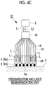
- Figs. 4A to 4D are longitudinal sectional views showing a curing device 21 and a curing method according to a third embodiment of the present invention.
- the pressurizing body 4 is configured such that a plurality of pressurizers 4A are adjacent to each other, and the laser beam L is individually supplied from the laser beam supply unit 5 to each of the pressurizers 4A.
- the plurality of pressurizers 4A can come into pressure-contact with and can be separated from the surface of the prepreg 2 independently to each other.
- the curing method for the prepreg 2 is performed as follows by the curing device 21.
- the uncured prepreg 2 is laminated (placed, wound, or the like) on the forming base 3, a predetermined molding tool, a jig, or the like (lamination step).
- the pressurizing body 4 comes into pressure-contact with the surface of the uncured prepreg 2, and the surface of the uncured prepreg 2 is pressurized by the pressurization surface 4a of the pressurizing body 4 (pressurization step).
- the pressurization is sequentially performed from one point of the pressurization range of the pressurizing body 4 toward the peripheral portion thereof.
- the pressurizer 4A positioned in the vicinity of the center comes into pressure-contact with the surface of the prepreg 2, the laser beam L is supplied to this pressurizer 4A, and the pressurized portion of the prepreg 2 is irradiated with the laser beam L (laser beam irradiation step).
- the resin material 2b of the prepreg 2 is softened by the irradiation of the laser beam L, and the bubbles B included inside the prepreg 2 are extracted to the outside by the pressing of the pressurizer 4A.
- the resin material 2b of the prepreg 2 is a thermosetting resin
- a curing reaction is generated by pressurizing the softened resin material 2b and the resin material 2b is cured.
- the resin material 2b is a thermoplastic resin
- the resin material 2b is cured by cooling the heated resin material 2b.
- the adjacent pressurizer 4A comes into pressure-contact with the surface of the prepreg 2, and similarly, the surface of the prepreg 2 is irradiated with the laser beam L.
- the pressurizers 4A come into pressure-contact with the surface of the prepreg 2, degassing and curing are completed, and the molded resin article 2A is formed.
- the above-described processes are repeated several times according to the size of the prepreg 2.
- the pressurizing body 4 (pressurizer 4A) is separated from the molded resin article 2A, and the molded resin article 2A is separated from the forming base 3 to complete the molded resin article 2A (mold release step).
- the pressurizing body 4 is configured such that the plurality of pressurizers 4A are adjacent to each other, the plurality of pressurizers 4A can come into pressure-contact with and can be separated from the surface of the prepreg 2 independently to each other, and the laser beam L is independently supplied from the laser beam supply unit 5 to each of the pressurizers 4A.
- the pressure-contacts of the pressurizers 4A are sequentially performed from one point within the pressurization range of the pressurizing body 4 toward the peripheral portion thereof, and the laser beam L can be supplied to only the pressure-contacted pressurizer 4A.
- the pressurization can be performed such that the bubbles B included in the uncured prepreg 2 are extracted from one point of the pressurization range toward the peripheral portion thereof, the degassing is favorably performed on the prepreg 2, and it is possible to cure the prepreg 2 with high strength.
- Figs. 5A to 5D are longitudinal sectional views showing a curing device 31 and a curing method according to a fourth embodiment of the present invention.
- the curing device 31 is configured to include a roll-type pressurizing body 4 which pressurizes the prepreg 2 laminated on the forming base 3, the molding tool, the jig, or the like, the laser beam supply unit 5 which emits the laser beam L to the prepreg 2 through the pressurizing body 4, the demultiplexer 13 which is the irradiation position adjustment unit adjusting the irradiation position of the laser beam L, and the optical fibers 12 and 14.
- the pressurizing body 4 is formed of a cylindrical shape, and the pressurization surface 4a configuring the outer peripheral surface of the pressurizing body 4 is a curved surface which can roll on the surface of the prepreg 2 while coming into pressure-contact with the surface of the prepreg 2.
- the shape of the pressurizing body 4 is not limited to the cylindrical shape and may be any shape such as a partial cylindrical shape, a spherical shape, a polygonal shape, or the like as long as the peripheral surface can roll on the surface of the prepreg 2 as the pressurization surface 4a. That is, the shape of the pressurizing body 4 may be appropriately selected according to the shape of the prepreg 2 to be molded.
- the center portion of the demultiplexer 13 which is positioned at the center portion of the pressurizing body 4 is pivotally supported by a pivot support portion (not shown), and the pressurizing body 4 can integrally rotate with the demultiplexer 13.
- the pivot support portion of the demultiplexer 13 can add a force by which the pressurization surface 4a of the pressurizing body 4 comes into pressure-contact with the surface of the prepreg 2.
- the laser beam supply unit 5 and the demultiplexer 13 are connected to each other by one optical fiber 12.
- the plurality of optical fibers 14 which extend in a radial direction from the demultiplexer 13 are inserted into the fiber insertion holes 4b which are formed from the inner surface of the pressurizing body 4 toward the pressurization surface 4a side. Since the fiber insertion holes 4b are closed in front of the pressurization surface 4a, the tip portions of the optical fibers 14 do not protrude from the pressurization surface 4a.
- the laser beam L which is supplied from the laser beam supply unit 5 to the demultiplexer 13 via one optical fiber 12 is supplied to the pressurizing body 4 via the plurality of optical fibers 14.
- the demultiplexer 13 selects the optical fibers 14 and supplies the laser beam L such that the laser beam L is emitted from the laser beam supply unit 5 to only the range of the pressurization surface 4a which comes into pressure-contact with the surface of the prepreg 2.
- the curing method for the prepreg 2 is performed as follows by the curing device 31 configured as described above.
- the uncured prepreg 2 is laminated (placed, wound, or the like) on the forming base 3, the predetermined molding tool, a jig, or the like (lamination step).
- the pressurizing body 4 slowly rolls while the pressurizing body 4 comes into pressure-contact with the surface of the uncured prepreg 2, and the surface is pressurized by the pressurization surface 4a (pressurization step).
- the pressurization is sequentially performed from one location of the surface of the prepreg 2 toward the peripheral portion thereof.
- the pressurizing body 4 rolls from one end of the prepreg 2 toward the other end.
- the laser beam from the laser beam supply unit 5 is emitted to the range of the pressurization surface 4a which comes into pressure-contact with the surface of the prepreg 2 while the pressurizing body 4 rolls to pressurize the surface of the prepreg 2 by the pressurization surface 4a (laser beam irradiation step).
- the laser beam L is supplied to only the optical fibers 14 corresponding to the range of the pressurization surface 4a which comes into pressure-contact with the surface of the prepreg 2 by the demultiplexer 13 which is the irradiation position adjustment unit. Accordingly, softening is performed from the pressurized portion of the prepreg 2.
- the bubbles B included inside the prepreg 2 are extracted from the range of the prepreg 2 which is pressurized by the pressurizing body 4 to the range of the prepreg 2 which is not pressurized.
- the resin material 2b of the prepreg 2 is a thermosetting resin
- a curing reaction is generated by pressurizing the softened resin material 2b and the resin material 2b is cured.
- the resin material 2b is cured by cooling the heated resin material 2b.
- the entire surface of the prepreg 2 is pressurized by irradiating the surface of the prepreg 2 with the laser beam L while slowing rolling the pressurizing body 4, degassing and curing are completed, and the molded resin article 2A is formed. Finally, as shown in Fig. 5D , the molded resin article 2A is separated from the forming base 3 to complete the molded resin article 2A (mold release step).
- the pressurization surface 4a of the pressurizing body 4 is formed in the shape such that the pressurization surface can roll on the surface of the prepreg 2 while coming into pressure-contact with the surface, and the laser beam L from the laser beam supply unit 5 is emitted to the range of the pressurization surface 4a which comes into pressure-contact with the surface of the prepreg 2.
- the pressurization surface 4a of the pressurizing body 4 which rolls on the surface of the prepreg 2 the laser beam L from the laser beam supply unit 5 is emitted to only the range which comes into pressure-contact with the surface of the prepreg 2. Therefore, the pressurization can be performed to continuously extract the bubbles included in the uncured prepreg 2 from the one point of the pressurization range toward the peripheral portion thereof, the degassing is favorably performed on the prepreg 2, and it is possible to cure the prepreg 2 with high strength. In addition, it is possible to omit the process of separating the pressurizing body 4 after curing the prepreg 2 from the prepreg 2.
- the curing devices 1, 11, 21, and 31 for a resin composite material and the curing methods of the embodiments it is possible to cure a fiber composite material such as the prepreg 2 with high strength by simple equipment using the laser beam L.
- the molded resin article 2A according to the present invention is pressurized and degassed during the curing, and the molded resin article 2A has high strength.
- the present invention is not limited to the configurations of the first to fourth embodiments, modifications and improvements can be appropriately applied within a scope which does not depart from the gist of the present invention, and an embodiment to which modifications and improvements are applied is included in the scope of the present invention.
- the entire shape of the pressurizing body 4, the shape of the pressurization surface 4a, or the like is not limited to the above-described embodiments.
- the shape of the prepreg 2 or the like other shape examples are considered.
Landscapes
- Engineering & Computer Science (AREA)
- Mechanical Engineering (AREA)
- Health & Medical Sciences (AREA)
- Physics & Mathematics (AREA)
- Chemical & Material Sciences (AREA)
- Composite Materials (AREA)
- Toxicology (AREA)
- Electromagnetism (AREA)
- Oral & Maxillofacial Surgery (AREA)
- Thermal Sciences (AREA)
- Manufacturing & Machinery (AREA)
- Casting Or Compression Moulding Of Plastics Or The Like (AREA)
- Heating, Cooling, Or Curing Plastics Or The Like In General (AREA)
Abstract
Description
- The present invention relates to a curing device for a resin composite material, a curing method, and a molded resin article.
- As described in
PTL 1 or the like, it is known that a characteristic improvement, enhancement of function, and a structure modification such as a composition modification of a specific portion of a resin material can be achieved by irradiating the resin material with laser beam so as to heat the specific portion of the resin material. In a composite material such as a prepreg, other thermosetting resins, or thermoplastic resins, it is considered to irradiate uncured materials or resins with a laser beam to heat the materials or the resins. Accordingly, it is possible to easily manufacture a molded resin article without using large equipment such as an autoclave, and it is possible to decrease manufacturing costs. - [PTL 1] Japanese Patent No.
3953891 - However, in a case where a resin composite material such as a prepreg is cured, in order to obtain predetermined strength, the resin composite material should be not only heated but be also pressurized simultaneously with the heating to remove bubbles. In general, an uncured resin composite material is molded into a predetermined shape of molded resin article using a molding tool, a jig, or the like, the molded resin composite material is enclosed by a vacuum bag so as to be evacuated in order to increase adhesion with respect to the jig, the molding tool, or the like. Thereafter, all resin composite materials are accommodated in a heater such as an autoclave and are cured while being heated, pressurized, and degassed.
- Since all pressurization members such as the jig, the molding tool, or the vacuum bag are formed of a material which blocks a laser beam, as described above, it is not possible to irradiate an uncured resin composite material with a laser beam so as to heat and cure the uncured resin composite material. Accordingly, it is indispensable to heat the uncured resin composite material by an oven, an autoclave, or the like, and it is necessary to prepare the equipment for each product shape, which causes an increase in the manufacturing cost of a molded resin article.
- The present invention is made in consideration of the above-described circumstances, and an object thereof is to provide a curing device for a resin composite material, a curing method, and molded resin article capable of curing a resin composite material with high strength by simple equipment using a laser beam.
- In order to achieve the object, the present invention adopts the following means.
- According to a first aspect of the present invention, there is provided a curing device for a resin composite material, including: a pressurizing body which is formed of a material through which a laser beam passes and comes into pressure-contact with a surface of an uncured resin composite material to pressurize the resin composite material; and a laser beam supply unit which irradiates the uncured resin composite material with the laser beam through the pressurizing body.
- According to the curing device having the above-described configuration, the surface of the resin composite material is irradiated with the laser beam supplied from the laser beam supply unit through the pressurizing body while the pressurizing body comes into pressure-contact with the surface of the uncured resin composite material so as to be pressurized, and the resin composite material can be heated and cured. In addition, degassing of the resin composite material is performed by heating the resin composite material while pressurizing the resin composite material and it is possible to increase molding strength.
- The pressurizing body may not be set to a size which comes into pressure-contact with the entire surface of the molded resin article manufactured by the resin composite material. That is, the pressurizing body is formed to have a size which comes into pressure-contact with only a portion of the surface of the resin composite material (molded resin article), and the entire resin composite material can be cured by repeating pressurization and heating with respect to the surface of the resin composite material partially by using the pressurizing body. Accordingly, unlike the related art, it is not necessary to prepare a vacuum bag capable of accommodating the entire resin composite material (molded resin article) or a heater such as an autoclave having a large capacity, and it is possible to easily cure the resin composite material using simple equipment.
- As a material of the pressurizing body, quartz glass is suitable. Since the quartz glass has good transmissivity of a laser beam, high heat resistance and chemical resistance, and high hardness, even if the cured resin material adheres to the pressurizing body, it is possible to easily separate the resin material from the pressurizing body, and it is possible to grind the surface of the pressurizing body again. Moreover, since the quartz glass is a material which is widely used, the quartz glass is relatively inexpensive and is suitably used as the material of the pressurizing body.
- In the above-described configuration, an irradiation position adjustment unit which moves an irradiation position of the laser beam supplied from the laser beam supply unit within a pressurization range of the pressurizing body may be provided.
- According to this configuration, for example, it is possible to move (expand) the irradiation position of the laser beam from one location within the pressurization range of the pressurizing body toward the peripheral portion thereof. Accordingly, by extracting bubbles included in the uncured resin composite material to the outside of the pressurization range and finally, removing all the bubbles within the pressurization range, it is possible to cure the resin composite material with high strength.
- In the above configuration, the laser beam supply unit may supply the laser beam to the resin composite material by an optical fiber. By supplying the laser beam to the resin composite material using the optical fiber having flexibility, it is possible to freely set a relative positional relationship between the laser beam supply unit and the pressurizing body, and it is possible to simplify the configuration of the curing device.
- In the above configuration, the laser beam supply unit may supply the laser beam to the resin composite material by a plurality of optical fibers, and the irradiation position adjustment unit may select any one of the plurality of optical fibers to supply the laser beam.
- According to this configuration, the relative positional relationship between the laser beam supply unit and the pressurizing body is freely set by the optical fiber having flexibility, the configuration of the curing device is simplified, the irradiation position of the laser beam is selected such that the bubbles included in the resin composite material are extracted to the outside of the pressurization range, and thereby, it is possible to increase the molding strength of the resin composite material.
- In the above configuration, preferably, the optical fiber is inserted into a fiber insertion hole formed in the pressurizing body and the fiber insertion hole is closed in front of a pressurization surface of the pressurizing body.
- According to this configuration, since the fiber insertion hole is not open to the pressurization surface of the pressurizing body, it is possible to prevent the tip portion of the optical fiber inserted into the fiber insertion hole from being contaminated due to a contact of the tip portion with respect to the uncured resin composite material, and it is possible to cure the resin composite material with high strength by favorably irradiating the resin composite material with the laser beam supplied via the optical fiber.
- In the above configuration, the pressurizing body may be configured such that a plurality of pressurizers are adjacent to each other, the plurality of pressurizers may come into pressure-contact with and be separated from the surface of the resin composite material independently to each other, and the laser beam may be independently supplied from the laser beam supply unit to each of the pressurizers.
- According to this configuration, the pressure-contacts of the pressurizers are sequentially performed from one point within the pressurization range of the pressurizing body toward the peripheral portion thereof, and the laser beam can be supplied to only the pressure-contacted pressurizer. Accordingly, the pressurization can be performed such that the bubbles included in the uncured resin composite material are extracted from one point of the pressurization range toward the peripheral portion thereof, the degassing is favorably performed on the resin composite material, and it is possible to cure the resin composite material with high strength.
- In the above configuration, the pressurization surface of the pressurizing body may have a shape such that the pressurization surface can roll on the surface of the resin composite material while coming into pressure-contact with the surface of the resin composite material, and the laser beam supply unit may emit the laser beam within a range of the pressurization surface which comes into pressure-contact with the surface of the resin composite material.
- According to this configuration, in the pressurization surface of the pressurizing body which rolls on the surface of the resin composite material, the laser beam from the laser beam supply unit can be emitted to only a range of the pressurization surface which comes into pressure-contact with the surface of the resin composite material. Therefore, the pressurization can be performed to continuously extract the bubbles included in the uncured resin composite material from the one point of the pressurization range toward the peripheral portion thereof, the degassing is favorably performed on the resin composite material, and it is possible to cure the resin composite material with high strength. In addition, it is possible to omit the process of separating the pressurizing body after curing the resin composite material from the resin composite material.
- According to a second aspect of the present invention, there is provided a curing method for a resin composite material, including: a pressurization step of allowing a pressurizing body formed of a material through which a laser beam passes to come into pressure-contact with a surface of an uncured resin composite material to pressurize the surface of the uncured resin composite material; and a laser beam irradiation step of irradiating the uncured resin composite material with a laser beam through the pressurizing body.
- In the curing method, first, in the pressurization step, the pressurizing body comes into pressure-contact with the surface of the uncured resin composite material, and next, in the laser beam irradiation step, the resin composite material is irradiated with the laser beam through the pressurizing body, and the curing of the resin composite material is performed.
- According to the curing method, it is possible to heat the resin composite material by the laser beam while pressurizing an arbitrary location of the uncured resin composite material by the pressurizing body. In addition, since the degassing of the resin composite material is performed by performing pressurizing simultaneously with the heating, it is possible to increase molding strength.
- The pressurizing body may not be set to a size which comes into pressure-contact with the entire surface of the molded resin article manufactured by the resin composite material. That is, the entire resin composite material can be cured by repeating pressurization and heating with respect to the surface of the resin composite material partially by using the pressurizing body formed to have a size which comes into pressure-contact with only a portion of the surface of the resin composite material (molded resin article). Accordingly, it is possible to easily cure the resin composite material by simple equipment.
- In the curing method, preferably, in the laser beam irradiation step, the irradiation position of the laser beam expands from one point of the pressurization range of the pressurizing body toward a peripheral portion thereof.
- According to this method, the resin composite material is softened from one location of the pressurization range of the pressurizing body toward the peripheral portion thereof by the heat of the laser beam, and simultaneously with this, bubbles included in the resin composite material are extracted from one location of the pressurization range toward the peripheral portion thereof. Accordingly, finally, all the bubbles within the pressurization range are removed, and it is possible to soften the resin composite material with high strength.
- In the curing method, preferably, in the pressurization step, pressurization is sequentially performed from one point of the pressurization range of the pressurizing body toward the peripheral portion thereof. In this way, since the pressurization is sequentially performed from one point of the pressurization range of the pressurizing body toward the peripheral portion thereof, it is possible to extract the bubbles included in the uncured resin composite material from one point of the pressurization range toward the peripheral portion, the degassing is favorably performed on the resin composite material, and it is possible to cure the resin composite material with high strength.
- According to a third aspect of the present invention, there is provided a molded resin article which is manufactured by the curing method for a resin composite material. since the molded resin article is pressurized and degassed during the curing, the molded resin article has high strength.
- As described above, according to the resin composite material and the curing device of the present invention, it is possible to cure a resin composite material with high strength by simple equipment using a laser beam. In addition, since the molded resin article according to the present invention is pressurized and degassed during the curing, the molded resin article has high strength.
-
-
Fig. 1A is a longitudinal sectional view of a lamination step showing a first embodiment of the present invention. -
Fig. 1B is a longitudinal sectional view of a pressurization step showing the first embodiment of the present invention. -
Fig. 1C is a longitudinal sectional view of a laser beam irradiation step showing the first embodiment of the present invention. -
Fig. 1D is a longitudinal sectional view of a mold release step showing a first embodiment of the present invention. -
Fig. 2 is a flowchart showing a curing method according to the present invention. -
Fig. 3A is a longitudinal sectional view of a lamination step showing a second embodiment of the present invention. -
Fig. 3B is a longitudinal sectional view of a pressurization step showing the second embodiment of the present invention. -
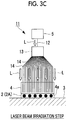
Fig. 3C is a longitudinal sectional view of a laser beam irradiation step showing the second embodiment of the present invention. -
Fig. 3D is a longitudinal sectional view of a mold release step showing a second embodiment of the present invention. -
Fig. 4A is a longitudinal sectional view of a lamination step showing a third embodiment of the present invention. -
Fig. 4B is a longitudinal sectional view of a pressurization and laser beam irradiation step showing the third embodiment of the present invention. -
Fig. 4C is a longitudinal sectional view of the pressurization and laser beam irradiation step showing the third embodiment of the present invention. -
Fig. 4D is a longitudinal sectional view of a mold release step showing the third embodiment of the present invention. -
Fig. 5A is a longitudinal sectional view of a lamination step showing a fourth embodiment of the present invention. -
Fig. 5B is a longitudinal sectional view of a pressurization and laser beam irradiation step showing the fourth embodiment of the present invention. -
Fig. 5C is a longitudinal sectional view of the pressurization and laser beam irradiation step showing the fourth embodiment of the present invention. -
Fig. 5D is a longitudinal sectional view of a mold release step showing the fourth embodiment of the present invention. - Hereinafter, a plurality of embodiments of the present invention will be described with reference to the drawings.
-
Figs. 1A to 1D are longitudinal sectional views showing acuring device 1 and a curing method according to a first embodiment of the present invention. - For example, a
curing device 1 is a device which heats and cures an uncured prepreg 2 (resin composite material) while pressurizing theprepreg 2 in a thickness direction thereof. As well known, theprepreg 2 is a semi-integrated and deformable intermediate molding material obtained by laminating or impregnating a thermosetting orthermoplastic resin material 2b on a fibrous reinforcingmaterial 2a such as carbon fibers or glass fibers. By laminating theprepreg 2 on a formingbase 3 or a molding tool (not shown), a jig, or the like and heating theprepreg 2 while pressurizing (compressing) theprepreg 2 in the thickness direction, bubbles (voids) B included between the fibrous reinforcingmaterial 2a and theresin material 2b are removed and a tough moldedresin article 2A is obtained. - The
curing device 1 is configured to include a pressurizingbody 4 which pressurizes theprepreg 2 laminated on the formingbase 3, the molding tool, the jig, or the like, a laserbeam supply unit 5 such as a laser oscillator which irradiates theprepreg 2 with a laser beam L through the pressurizingbody 4, and an irradiationposition adjustment unit 6 which adjusts an irradiation position of the laser beam L. - The pressurizing
body 4 is formed of a material through which the laser beam L favorably passes. Most preferably, the material is quartz glass. In addition, in the present embodiment, the pressurizingbody 4 is formed in a rectangular parallelepiped shape having aflat pressurization surface 4a. However, the pressurizingbody 4 may be formed in a flat plate shape, a shape having a curved surface, or other shapes as long as it has a pressurization surface shape which comes into close contact with the surface of theprepreg 2. The shape of the formingbase 3 or the like on which theprepreg 2 is placed is not limited to a flat shape and may be a curved shape, or the like. - The laser
beam supply unit 5 is a configuration portion which emits the laser beam L such as a CO2 laser or an YAG laser, and the irradiationposition adjustment unit 6 is a configuration portion which moves an irradiation position of the laser beam L emitted from the laserbeam supply unit 5 within a pressurization range of theprepreg 2 performed by the pressurizingbody 4. - The pressurizing
body 4 comes into pressure-contact with the surface of theprepreg 2 by a force of a drive device (not shown), weight of a mass, or the like. Meanwhile, the laser beam L emitted from the laserbeam supply unit 5 is required so as not to be blocked by the drive device, the weight, or the like. - For example, as the irradiation
position adjustment unit 6, an irradiationdirection adjustment unit 6a which is incorporated into the laserbeam supply unit 5 and adjusts an irradiation direction (irradiation angle) of the laser beam L, aposition adjustment unit 6b which moves the position of the entire laserbeam supply unit 5 in a surface direction of theprepreg 2, or the like is considered. However, other configurations may be adopted as long as these can move the irradiation position of the laser beam L with respect to theprepreg 2. - The curing method for the
prepreg 2 is performed as follows by thecuring device 1 configured as described above. In addition,Fig. 2 is a flowchart showing the curing method for theprepreg 2. - First, as shown in
Fig. 1A , theuncured prepreg 2 is laminated (placed, wound, or the like) on the formingbase 3, a predetermined molding tool, a jig, or the like (lamination step S1). - Next, as shown in
Fig. 1B , the pressurizingbody 4 comes into pressure-contact with the surface of theuncured prepreg 2, and the surface of theuncured prepreg 2 is pressurized by thepressurization surface 4a of the pressurizing body 4 (pressurization step S2). In this case, a pressurizing force is set such that bubbles B included inside theprepreg 2 are extracted to the outside. - Next, as shown in
Fig. 1C , the laserbeam supply unit 5 irradiates theprepreg 2 with the laser beam L (laser beam irradiation step S3). The laser beam L passes through the pressurizingbody 4, theprepreg 2 is irradiated with the laser beam L, and theprepreg 2 is heated and softened. In this case, the irradiation position of the laser beam L is moved from one point of the pressurization range of the pressurizingbody 4, for example, the center portion toward the peripheral portion thereof by the irradiationposition adjustment unit 6. - In addition, if the pressurization (pressurization step S2) performed by the pressurizing
body 4 and the irradiation (laser beam irradiation step S3) of the laser beam L may simultaneously start, and the pressurization (pressurization step S2) performed by the pressurizingbody 4 may start after the softening of theresin material 2b performed by the irradiation (laser beam irradiation step S3) of the laser beam L starts. - Sine the irradiation position of the laser beam L moves from the center portion of the pressurization range of the pressurizing
body 4 toward the peripheral portion, theresin material 2b of theprepreg 2 is sequentially softened from the center portion of the pressurization range toward the peripheral portion thereof, the bubbles B included in theprepreg 2 are extracted from the center portion toward the peripheral portion, and finally, all the bubbles B within the pressurization range are removed. - In a case where the
resin material 2b of theprepreg 2 is a thermosetting resin, a curing reaction is generated by pressurizing the softenedresin material 2b and theresin material 2b is cured. Meanwhile, in a case where theresin material 2b is a thermoplastic resin, theresin material 2b is cured by cooling theheated resin material 2b. - In addition, the irradiation start position of the laser beam L may not necessarily be positioned at the center portion of the pressurization range of the pressurizing
body 4. For example, initially, one end portion of the pressurization range is irradiated with the laser beam, and the irradiation position may move from the one end portion of the pressurization range toward the other end portion thereof. Even in this case, similarly, the bubbles B included in theprepreg 2 can be extracted from the one end portion of the pressurization range toward the other end portion thereof. - If the
prepreg 2 is cured by the pressurization performed by the pressurizingbody 4 and the irradiation of the laser beam L, the position at which the pressurizingbody 4 comes into pressure-close with theprepreg 2 is shifted, and the pressurization performed by the pressurizingbody 4 and the irradiation of the laser beam L are performed again. By repeating this, the entire of theprepreg 2 is cured and the moldedresin article 2A is formed. - Finally, as shown in
Fig. 1D , the pressurizingbody 4 is separated from the moldedresin article 2A, and the moldedresin article 2A is separated from the formingbase 3 to complete the moldedresin article 2A (mold release step S4). - According to the above-described
curing device 1 and curing method, the surface of theprepreg 2 is irradiated with the laser beam L supplied from the laserbeam supply unit 5 through the pressurizingbody 4 while the pressurizingbody 4 comes into pressure-contact with the surface of theuncured prepreg 2 positioned at an arbitrary location thereof and is pressurized, and theprepreg 2 can be heated and cured. In addition, degassing of theprepreg 2 is performed by heating theprepreg 2 while pressurizing theprepreg 2 and it is possible to increase molding strength of the moldedresin article 2A. - The pressurizing
body 4 may not be set to a size which comes into pressure-contact with the entire surface of the moldedresin article 2A manufactured by theprepreg 2. That is, the pressurizingbody 4 is formed to have a size or a shape which comes into pressure-contact with only a portion of the surface of the prepreg 2 (moldedresin article 2A), and theentire prepreg 2 can be cured by partially repeating pressurization and heating with respect to the surface of theprepreg 2 a plurality of times using the pressurizingbody 4. Accordingly, unlike the related art, it is not necessary to prepare a vacuum bag capable of accommodating the entire prepreg 2 (moldedresin article 2A) or a heater such as an autoclave having a large capacity, and it is possible to easily heat a thermosetting resin or a thermoplastic resin such as aprepreg 2 using simple equipment. - Since the
curing device 1 includes the irradiationposition adjustment unit 6 which moves the irradiation position of the laser beam L supplied from the laserbeam supply unit 5 within the pressurization range of the pressurizingbody 4, as described above, it is possible to expand the irradiation position of the laser beam L from one point of the pressurization range of the pressurizingbody 4 toward the peripheral portion thereof, for example, it is possible to expand the irradiation position in an annular shape. - In this way, by expanding the irradiation position of the laser beam L from one point of the pressurization range toward the peripheral portion thereof, the
prepreg 2 is softened from one location of the pressurization range toward the peripheral portion thereof by the heat of the laser beam L. At the same time, the bubbles B included in theuncured prepreg 2 are extracted toward the peripheral portion. Accordingly, finally, all the bubbles B within the pressurization range are removed, and it is possible to soften theprepreg 2 with high strength. - In this
curing device 1, quartz glass is used as the material of the pressurizingbody 4. Since the quartz glass has good transmissivity of the laser beam L, high heat resistance and chemical resistance, and high hardness, even if the cured resin material adheres to the pressurizingbody 4, it is possible to easily separate the resin material from the pressurizingbody 4, and it is possible to grind the surface of the pressurizingbody 4 again. Moreover, since the quartz glass is a material which is widely used, the quartz glass is relatively inexpensive. Therefore, the quartz glass is suitably used as the material of the pressurizingbody 4. -
Figs. 3A to 3D are longitudinal sectional views showing acuring device 11 and a curing method according to a second embodiment of the present invention. - In this
curing device 11, the laserbeam supply unit 5 supplies the laser beam L to theprepreg 2 via oneoptical fiber 12, ademultiplexer 13 which is an irradiation position adjustment unit, and a plurality ofoptical fibers 14. Other configurations are similar to those of thecuring device 1 of the first embodiment. - As shown in
Fig. 3A to be partially enlarged, the tip portions of the plurality ofoptical fibers 14 are inserted into thefiber insertion holes 4b formed from the upper surface side of the pressurizingbody 4 toward thepressurization surface 4a side, and thefiber insertion holes 4b are closed in front of thepressurization surface 4a. Accordingly, the tip portion of eachoptical fiber 14 does not protrude from thepressurization surface 4a. - The laser beam L supplied from the laser
beam supply unit 5 to thedemultiplexer 13 via oneoptical fiber 12 is supplied from the plurality ofoptical fibers 14 to the pressurizingbody 4. In this case, thedemultiplexer 13 can move the irradiation position of the laser beam L within the pressurization range of the pressurizingbody 4. Specifically, by sequentially supplying the laser beam L from theoptical fiber 14 positioned at one point within the pressurization range (within thepressurization surface 4a) of the pressurizingbody 4 among the plurality offibers 14 toward the optical fibers positioned at the peripheral portion, it is possible to expand the irradiation range of the laser beam L in an annular shape. - The curing method for the
prepreg 2 is performed as follows by the curingdevice 11 configured as described above. This curing method is also performed according to the procedure of the flowchart shown inFig. 2 . - First, as shown in
Fig. 3A , theuncured prepreg 2 is laminated (placed, wound, or the like) on the formingbase 3, a predetermined molding tool, a jig, or the like (lamination step S1). - Next, as shown in
Fig. 3B , the pressurizingbody 4 comes into pressure-contact with the surface of theuncured prepreg 2, and the surface of theuncured prepreg 2 is pressurized by thepressurization surface 4a of the pressurizing body 4 (pressurization step S2). In this case, a pressurizing force is set such that bubbles B included inside theprepreg 2 are extracted to the outside. - Next, as shown in
Fig. 3C , the laserbeam supply unit 5 irradiates theprepreg 2 with laser beam L via theoptical fiber 12, thedemultiplexer 13, theoptical fibers 14, and the pressurizing body 4 (laser beam irradiation step S3). The laser beam L passes through the pressurizingbody 4, theprepreg 2 is irradiated with the laser beam L, and theprepreg 2 is heated. - In this case, the laser beam L is emitted from each
optical fiber 14 such that the irradiation position of the laser beam L is moved from one point of the pressurization range of the pressurizingbody 4, for example, the center portion toward the peripheral portion thereof by thedemultiplexer 13 which is an irradiation position adjustment unit. - Moreover, the pressurization (pressurization step S2) of the pressurizing
body 4 and the irradiation (laser beam irradiation step S3) of the laser beam L may simultaneously start, and the pressurization (pressurization step S2) performed by the pressurizingbody 4 may start after the softening of theresin material 2b performed by the irradiation (laser beam irradiation step S3) of the laser beam L starts. - By moving the irradiation position of the laser beam L from the center portion of the pressurization range of the pressurizing
body 4 toward the peripheral portion thereof, theresin material 2b of theprepreg 2 is sequentially softened from the center portion of the pressurization range toward the peripheral portion, and the bubbles B included in theprepreg 2 are extracted from the center portion toward the peripheral portion simultaneously with the softening. - In a case where the
resin material 2b of theprepreg 2 is a thermosetting resin, a curing reaction is generated by pressurizing the softenedresin material 2b and theresin material 2b is cured. Meanwhile, in a case where theresin material 2b is a thermoplastic resin, theresin material 2b is cured by cooling theheated resin material 2b. - In addition, similarly to the first embodiment, the irradiation start position of the laser beam L may not necessarily be positioned at the center portion of the pressurization range of the pressurizing
body 4. In addition, similarly to the first embodiment, by shifting the pressure-contact position of the pressurizingbody 4 every theprepreg 2 is hardened and repeating the pressurization performed by the pressurizingbody 4 and the irradiation of the laser beam L again, theentire prepreg 2 is hardened and the moldedresin article 2A is formed. - Finally, as shown in
Fig. 3D , the pressurizingbody 4 is separated from the moldedresin article 2A, and the moldedresin article 2A is separated from the formingbase 3 to complete the moldedresin article 2A (mold release step S4). - According to the
curing device 11 and the curing method of the second embodiment, effects similar to those of thecuring device 1 and the curing method of the first embodiment are obtained. In addition to the effects, since thecuring device 11 supplies the laser beam L from the laserbeam supply unit 5 to the pressurizingbody 4 via the softoptical fibers beam supply unit 5 and the pressurizingbody 4. That is, since the laser beam L which straightly advances in a space is freely curved and can be supplied to the pressurizingbody 4, for example, the device is configured such that only the pressurizingbody 4 can move in a state where the laserbeam supply unit 5 is fixed. Accordingly, it is possible to simplify (freely set) the configuration of thecuring device 11. - In addition, by supplying the laser beam L from the
optical fiber 14 positioned at one point within the pressurization range of the pressurizingbody 4 among the plurality ofoptical fibers 14 toward theoptical fibers 14 positioned on the peripheral portion thereof by thedemultiplexer 13, it is possible to soften theresin material 2b in this order. Accordingly, it is possible to increase the molding strength of theprepreg 2 by extracting the bubbles included in theprepreg 2 from one point within the pressurization range toward the peripheral portion thereof. - In addition, since the plurality of
optical fibers 14 are inserted into thefiber insertion holes 4b formed in the pressurizingbody 4 and thefiber insertion holes 4b are closed in front of thepressurization surface 4a of the pressurizingbody 4, it is possible to prevent the tip portion of eachoptical fiber 14 from being contaminated due to a contact of the tip portion with respect to the uncured resin material. Accordingly, it is possible to cure theprepreg 2 with high strength by favorably irradiating theprepreg 2 with the laser beam L supplied via theoptical fibers 14. -
Figs. 4A to 4D are longitudinal sectional views showing acuring device 21 and a curing method according to a third embodiment of the present invention. - In the
curing device 21, the pressurizingbody 4 is configured such that a plurality ofpressurizers 4A are adjacent to each other, and the laser beam L is individually supplied from the laserbeam supply unit 5 to each of thepressurizers 4A. The plurality ofpressurizers 4A can come into pressure-contact with and can be separated from the surface of theprepreg 2 independently to each other. - Since other portions are similar to those of the
curing device 11 of the second embodiment, the same numeral reference is assigned to each portion, and detail descriptions thereof are omitted. - The curing method for the
prepreg 2 is performed as follows by the curingdevice 21. - First, as shown in
Fig. 4A , theuncured prepreg 2 is laminated (placed, wound, or the like) on the formingbase 3, a predetermined molding tool, a jig, or the like (lamination step). - Next, as shown in
Fig. 4B , the pressurizingbody 4 comes into pressure-contact with the surface of theuncured prepreg 2, and the surface of theuncured prepreg 2 is pressurized by thepressurization surface 4a of the pressurizing body 4 (pressurization step). In this case, the pressurization is sequentially performed from one point of the pressurization range of the pressurizingbody 4 toward the peripheral portion thereof. That is, among the plurality ofpressurizers 4A arranged to be adjacent to each other, for example, first, thepressurizer 4A positioned in the vicinity of the center comes into pressure-contact with the surface of theprepreg 2, the laser beam L is supplied to thispressurizer 4A, and the pressurized portion of theprepreg 2 is irradiated with the laser beam L (laser beam irradiation step). - The
resin material 2b of theprepreg 2 is softened by the irradiation of the laser beam L, and the bubbles B included inside theprepreg 2 are extracted to the outside by the pressing of thepressurizer 4A. In a case where theresin material 2b of theprepreg 2 is a thermosetting resin, a curing reaction is generated by pressurizing the softenedresin material 2b and theresin material 2b is cured. Meanwhile, in a case where theresin material 2b is a thermoplastic resin, theresin material 2b is cured by cooling theheated resin material 2b. - Next, the
adjacent pressurizer 4A comes into pressure-contact with the surface of theprepreg 2, and similarly, the surface of theprepreg 2 is irradiated with the laser beam L. By repeating this, as shown inFig. 4C , all thepressurizers 4A come into pressure-contact with the surface of theprepreg 2, degassing and curing are completed, and the moldedresin article 2A is formed. The above-described processes are repeated several times according to the size of theprepreg 2. - Finally, as shown in
Fig. 4D , the pressurizing body 4 (pressurizer 4A) is separated from the moldedresin article 2A, and the moldedresin article 2A is separated from the formingbase 3 to complete the moldedresin article 2A (mold release step). - According to the
curing device 21 and the curing method, effects similar to those of thecuring device 11 and the curing method of the second embodiment are obtained. In addition to the effects, in thecuring device 21, the pressurizingbody 4 is configured such that the plurality ofpressurizers 4A are adjacent to each other, the plurality ofpressurizers 4A can come into pressure-contact with and can be separated from the surface of theprepreg 2 independently to each other, and the laser beam L is independently supplied from the laserbeam supply unit 5 to each of thepressurizers 4A. - Accordingly, in the pressurization step, the pressure-contacts of the
pressurizers 4A are sequentially performed from one point within the pressurization range of the pressurizingbody 4 toward the peripheral portion thereof, and the laser beam L can be supplied to only the pressure-contactedpressurizer 4A. Accordingly, the pressurization can be performed such that the bubbles B included in theuncured prepreg 2 are extracted from one point of the pressurization range toward the peripheral portion thereof, the degassing is favorably performed on theprepreg 2, and it is possible to cure theprepreg 2 with high strength. -
Figs. 5A to 5D are longitudinal sectional views showing acuring device 31 and a curing method according to a fourth embodiment of the present invention. - The curing
device 31 is configured to include a roll-type pressurizing body 4 which pressurizes theprepreg 2 laminated on the formingbase 3, the molding tool, the jig, or the like, the laserbeam supply unit 5 which emits the laser beam L to theprepreg 2 through the pressurizingbody 4, thedemultiplexer 13 which is the irradiation position adjustment unit adjusting the irradiation position of the laser beam L, and theoptical fibers - For example, the pressurizing
body 4 is formed of a cylindrical shape, and thepressurization surface 4a configuring the outer peripheral surface of the pressurizingbody 4 is a curved surface which can roll on the surface of theprepreg 2 while coming into pressure-contact with the surface of theprepreg 2. The shape of the pressurizingbody 4 is not limited to the cylindrical shape and may be any shape such as a partial cylindrical shape, a spherical shape, a polygonal shape, or the like as long as the peripheral surface can roll on the surface of theprepreg 2 as thepressurization surface 4a. That is, the shape of the pressurizingbody 4 may be appropriately selected according to the shape of theprepreg 2 to be molded. - The center portion of the
demultiplexer 13 which is positioned at the center portion of the pressurizingbody 4 is pivotally supported by a pivot support portion (not shown), and the pressurizingbody 4 can integrally rotate with thedemultiplexer 13. In addition, the pivot support portion of thedemultiplexer 13 can add a force by which thepressurization surface 4a of the pressurizingbody 4 comes into pressure-contact with the surface of theprepreg 2. - The laser
beam supply unit 5 and thedemultiplexer 13 are connected to each other by oneoptical fiber 12. As shown inFig. 5A to be partially enlarged, the plurality ofoptical fibers 14 which extend in a radial direction from thedemultiplexer 13 are inserted into thefiber insertion holes 4b which are formed from the inner surface of the pressurizingbody 4 toward thepressurization surface 4a side. Since thefiber insertion holes 4b are closed in front of thepressurization surface 4a, the tip portions of theoptical fibers 14 do not protrude from thepressurization surface 4a. - The laser beam L which is supplied from the laser
beam supply unit 5 to thedemultiplexer 13 via oneoptical fiber 12 is supplied to the pressurizingbody 4 via the plurality ofoptical fibers 14. In this case, thedemultiplexer 13 selects theoptical fibers 14 and supplies the laser beam L such that the laser beam L is emitted from the laserbeam supply unit 5 to only the range of thepressurization surface 4a which comes into pressure-contact with the surface of theprepreg 2. - The curing method for the
prepreg 2 is performed as follows by the curingdevice 31 configured as described above. - First, as shown in
Fig. 5A , theuncured prepreg 2 is laminated (placed, wound, or the like) on the formingbase 3, the predetermined molding tool, a jig, or the like (lamination step). - Next, as shown in
Figs. 5B to 5C , the pressurizingbody 4 slowly rolls while the pressurizingbody 4 comes into pressure-contact with the surface of theuncured prepreg 2, and the surface is pressurized by thepressurization surface 4a (pressurization step). In this case, the pressurization is sequentially performed from one location of the surface of theprepreg 2 toward the peripheral portion thereof. As an example, the pressurizingbody 4 rolls from one end of theprepreg 2 toward the other end. - In this way, the laser beam from the laser
beam supply unit 5 is emitted to the range of thepressurization surface 4a which comes into pressure-contact with the surface of theprepreg 2 while the pressurizingbody 4 rolls to pressurize the surface of theprepreg 2 by thepressurization surface 4a (laser beam irradiation step). In this case, the laser beam L is supplied to only theoptical fibers 14 corresponding to the range of thepressurization surface 4a which comes into pressure-contact with the surface of theprepreg 2 by thedemultiplexer 13 which is the irradiation position adjustment unit. Accordingly, softening is performed from the pressurized portion of theprepreg 2. - If the
resin material 2b of theprepreg 2 is softened by the irradiation of the laser beam L, the bubbles B included inside theprepreg 2 are extracted from the range of theprepreg 2 which is pressurized by the pressurizingbody 4 to the range of theprepreg 2 which is not pressurized. In a case where theresin material 2b of theprepreg 2 is a thermosetting resin, a curing reaction is generated by pressurizing the softenedresin material 2b and theresin material 2b is cured. Meanwhile, in a case where theresin material 2b is a thermoplastic resin, theresin material 2b is cured by cooling theheated resin material 2b. - In this way, the entire surface of the
prepreg 2 is pressurized by irradiating the surface of theprepreg 2 with the laser beam L while slowing rolling the pressurizingbody 4, degassing and curing are completed, and the moldedresin article 2A is formed. Finally, as shown inFig. 5D , the moldedresin article 2A is separated from the formingbase 3 to complete the moldedresin article 2A (mold release step). - According to the
curing device 31 and the curing method, effects similar to those of thecuring device 21 and the curing method of the third embodiment are obtained. In addition to the effects, in thecuring device 31, thepressurization surface 4a of the pressurizingbody 4 is formed in the shape such that the pressurization surface can roll on the surface of theprepreg 2 while coming into pressure-contact with the surface, and the laser beam L from the laserbeam supply unit 5 is emitted to the range of thepressurization surface 4a which comes into pressure-contact with the surface of theprepreg 2. - Accordingly, in the
pressurization surface 4a of the pressurizingbody 4 which rolls on the surface of theprepreg 2, the laser beam L from the laserbeam supply unit 5 is emitted to only the range which comes into pressure-contact with the surface of theprepreg 2. Therefore, the pressurization can be performed to continuously extract the bubbles included in theuncured prepreg 2 from the one point of the pressurization range toward the peripheral portion thereof, the degassing is favorably performed on theprepreg 2, and it is possible to cure theprepreg 2 with high strength. In addition, it is possible to omit the process of separating the pressurizingbody 4 after curing theprepreg 2 from theprepreg 2. - As described above, according to the
curing devices prepreg 2 with high strength by simple equipment using the laser beam L. In addition, the moldedresin article 2A according to the present invention is pressurized and degassed during the curing, and the moldedresin article 2A has high strength. - In addition, the present invention is not limited to the configurations of the first to fourth embodiments, modifications and improvements can be appropriately applied within a scope which does not depart from the gist of the present invention, and an embodiment to which modifications and improvements are applied is included in the scope of the present invention.
- For example, the entire shape of the pressurizing
body 4, the shape of thepressurization surface 4a, or the like is not limited to the above-described embodiments. Regarding the shape of theprepreg 2 or the like, other shape examples are considered. -
- 1, 11, 21, 31: curing device
- 2: prepreg (resin composite material)
- 2A: molded resin article
- 4: pressurizing body
- 4A: pressurizer
- 4a: pressurization surface
- 4b: fiber insertion hole
- 5: laser beam supply unit
- 6: irradiation position adjustment unit
- 12, 14: optical fiber
- 13: demultiplexer (irradiation position adjustment unit)
- L: laser beam
- S1: lamination step
- S2: pressurization step
- S3: laser beam irradiation step
- S4: mold release step
Claims (12)
- A curing device for a resin composite material, comprising:a pressurizing body which is formed of a material through which a laser beam passes and comes into pressure-contact with a surface of an uncured resin composite material to pressurize the resin composite material; anda laser beam supply unit which irradiates the uncured resin composite material with the laser beam through the pressurizing body.
- The curing device for a resin composite material according to claim 1,
wherein a material of the pressurizing body is quartz glass. - The curing device for a resin composite material according to claim 1 or 2, further comprising:an irradiation position adjustment unit which moves an irradiation position of the laser beam supplied from the laser beam supply unit within a pressurization range of the pressurizing body.
- The curing device for a resin composite material according to any one of claims 1 to 3,
wherein the laser beam supply unit supplies the laser beam to the resin composite material by an optical fiber. - The curing device for a resin composite material according to claim 4,
wherein the laser beam supply unit supplies the laser beam to the resin composite material by a plurality of optical fibers, and
wherein the irradiation position adjustment unit selects any one of the plurality of optical fibers to supply the laser beam. - The curing device for a resin composite material according to claim 4 or 5,
wherein the optical fiber is inserted into a fiber insertion hole formed in the pressurizing body and the fiber insertion hole is closed in front of a pressurization surface of the pressurizing body. - The curing device for a resin composite material according to any one of claims 1 to 6,
wherein the pressurizing body is configured such that a plurality of pressurizers are adjacent to each other,
wherein the plurality of pressurizers can come into pressure-contact with and be separated from the surface of the resin composite material independently to each other, and
wherein the laser beam is independently supplied from the laser beam supply unit to each of the pressurizers. - The curing device for a resin composite material according to any one of claims 1 to 6,
wherein the pressurization surface of the pressurizing body has a shape such that the pressurization surface can roll on the surface of the resin composite material while coming into pressure-contact with the surface of the resin composite material, and
wherein the laser beam supply unit emits the laser beam within a range of the pressurization surface which comes into pressure-contact with the surface of the resin composite material. - A curing method for a resin composite material, comprising:a pressurization step of allowing a pressurizing body formed of a material through which a laser beam passes to come into pressure-contact with a surface of an uncured resin composite material to pressurize the surface of the uncured resin composite material; anda laser beam irradiation step of irradiating the uncured resin composite material with a laser beam through the pressurizing body.
- The curing method for a resin composite material according to claim 9,
wherein in the laser beam irradiation step, the irradiation position of the laser beam expands from one point of the pressurization range of the pressurizing body toward a peripheral portion thereof. - The curing method for a resin composite material according to claim 9 or 10,
wherein in the pressurization step, pressurization is sequentially performed from one point of the pressurization range of the pressurizing body toward the peripheral portion thereof. - A molded resin article which is manufactured by the curing method for a resin composite material according to any one of claims 9 to 11.
Applications Claiming Priority (2)
| Application Number | Priority Date | Filing Date | Title |
|---|---|---|---|
| JP2015113320A JP6742697B2 (en) | 2015-06-03 | 2015-06-03 | Curing device for resin composite material and curing method |
| PCT/JP2016/065167 WO2016194676A1 (en) | 2015-06-03 | 2016-05-23 | Curing device for resin composite material, curing method, and molded resin article |
Publications (2)
| Publication Number | Publication Date |
|---|---|
| EP3260263A1 true EP3260263A1 (en) | 2017-12-27 |
| EP3260263A4 EP3260263A4 (en) | 2018-05-23 |
Family
ID=57441378
Family Applications (1)
| Application Number | Title | Priority Date | Filing Date |
|---|---|---|---|
| EP16803111.0A Withdrawn EP3260263A4 (en) | 2015-06-03 | 2016-05-23 | Curing device for resin composite material, curing method, and molded resin article |
Country Status (5)
| Country | Link |
|---|---|
| US (1) | US20180250852A1 (en) |
| EP (1) | EP3260263A4 (en) |
| JP (1) | JP6742697B2 (en) |
| CN (1) | CN107428039A (en) |
| WO (1) | WO2016194676A1 (en) |
Families Citing this family (7)
| Publication number | Priority date | Publication date | Assignee | Title |
|---|---|---|---|---|
| US9181639B2 (en) | 2006-05-19 | 2015-11-10 | Massachusetts Institute Of Technology | Continuous process for the production of nanostructures including nanotubes |
| US8337979B2 (en) | 2006-05-19 | 2012-12-25 | Massachusetts Institute Of Technology | Nanostructure-reinforced composite articles and methods |
| EP4516846A3 (en) * | 2017-09-15 | 2025-12-24 | Massachusetts Institute of Technology | Low-defect fabrication of composite materials |
| US11345790B2 (en) * | 2019-08-13 | 2022-05-31 | International Business Machines Corporation | Reducing resin squeeze-out |
| CN111770675B (en) * | 2020-06-19 | 2022-05-06 | 深圳市联得自动化装备股份有限公司 | Hot pressing method and hot pressing equipment for manufacturing curved surface module, curved surface module and application |
| CN111844799B (en) * | 2020-07-22 | 2022-03-29 | 江苏新扬新材料股份有限公司 | Forming method of aviation particle separator |
| CN117162540B (en) * | 2023-11-02 | 2024-01-26 | 湖南科技大学 | Microwave ultrasonic curing forming equipment and curing forming method for resin matrix composite material |
Family Cites Families (20)
| Publication number | Priority date | Publication date | Assignee | Title |
|---|---|---|---|---|
| JP3148519B2 (en) * | 1994-06-24 | 2001-03-19 | シャープ株式会社 | Manufacturing method of liquid crystal display element |
| US6099783A (en) * | 1995-06-06 | 2000-08-08 | Board Of Trustees Operating Michigan State University | Photopolymerizable compositions for encapsulating microelectronic devices |
| DE19801346C1 (en) * | 1998-01-16 | 1999-02-18 | Sonotronic Nagel Gmbh | Shape embossing apparatus for fusible materials |
| JP3596421B2 (en) * | 2000-04-26 | 2004-12-02 | トヨタ自動車株式会社 | How to increase the strength of resin molded products |
| ES2249527T3 (en) * | 2002-10-02 | 2006-04-01 | Leister Process Technologies | PROCEDURE AND DEVICE FOR JOINING THREE-DIMENSIONAL PLASTIC PARTS THROUGH A LASER RAY. |
| JP2004148732A (en) * | 2002-10-31 | 2004-05-27 | Sakura Gomme Kk | Apparatus for manufacturing molding of fiber-reinforced photo-hardening resin |
| US6975788B2 (en) * | 2002-12-09 | 2005-12-13 | Lucent Technologies, Inc. | Optical switch having combined input/output fiber array |
| US6906300B2 (en) * | 2003-08-13 | 2005-06-14 | The Boeing Company | Consolidation device and method |
| JP2005081396A (en) * | 2003-09-09 | 2005-03-31 | Nissan Motor Co Ltd | Laser welding apparatus and laser welding method |
| US7677877B2 (en) * | 2005-11-04 | 2010-03-16 | Asml Netherlands B.V. | Imprint lithography |
| JP5408972B2 (en) * | 2008-11-26 | 2014-02-05 | 日東電工株式会社 | Sheet assembly manufacturing method |
| JP4430131B1 (en) * | 2009-08-10 | 2010-03-10 | 静岡県 | Laser melting belt material and laser bonding method |
| JP5548579B2 (en) * | 2010-10-15 | 2014-07-16 | 日東電工株式会社 | Manufacturing method of polarizing film |
| JP5860241B2 (en) * | 2011-08-02 | 2016-02-16 | 日東電工株式会社 | Resin member joining method |
| EP2815870B1 (en) * | 2012-02-14 | 2019-09-11 | Seidensha Electronics Co., Ltd | Device for welding thermoplastic resin material |
| JP5915370B2 (en) * | 2012-05-16 | 2016-05-11 | ソニー株式会社 | Electrophoretic element, electrophoretic display device, electronic apparatus, and method for manufacturing electrophoretic element |
| WO2014123022A1 (en) * | 2013-02-05 | 2014-08-14 | 株式会社日立製作所 | Laser joining apparatus and laser joining method |
| KR102110839B1 (en) * | 2013-07-24 | 2020-05-15 | 삼성디스플레이 주식회사 | Display apparatus and method of manufacturing the same |
| CN103660286B (en) * | 2013-11-25 | 2016-08-24 | 王瑛玮 | A kind of composite material and preparation method thereof |
| CN103935044B (en) * | 2014-05-07 | 2017-01-11 | 王瑛玮 | Preparation of composite material by scanning prepreg through laser |
-
2015
- 2015-06-03 JP JP2015113320A patent/JP6742697B2/en active Active
-
2016
- 2016-05-23 CN CN201680016721.9A patent/CN107428039A/en active Pending
- 2016-05-23 EP EP16803111.0A patent/EP3260263A4/en not_active Withdrawn
- 2016-05-23 US US15/560,347 patent/US20180250852A1/en not_active Abandoned
- 2016-05-23 WO PCT/JP2016/065167 patent/WO2016194676A1/en not_active Ceased
Also Published As
| Publication number | Publication date |
|---|---|
| JP2016221929A (en) | 2016-12-28 |
| CN107428039A (en) | 2017-12-01 |
| WO2016194676A1 (en) | 2016-12-08 |
| EP3260263A4 (en) | 2018-05-23 |
| JP6742697B2 (en) | 2020-08-19 |
| US20180250852A1 (en) | 2018-09-06 |
Similar Documents
| Publication | Publication Date | Title |
|---|---|---|
| US20180250852A1 (en) | Curing device for resin composite material, curing method, and molded resin article | |
| US10300632B2 (en) | Method of producing preform | |
| JP6109196B2 (en) | Method and apparatus for producing a three-dimensional preform from a fiber scrim during the production of a fiber reinforced molded part | |
| JP5721557B2 (en) | Method for manufacturing reinforced honeycomb core and sandwich panel | |
| JP6231015B2 (en) | Method and apparatus for producing a three-dimensional preform from a fiber scrim during the production of a fiber reinforced molded part | |
| JP2016221929A5 (en) | ||
| EP3263308A1 (en) | Curing device for resin composite material, curing method, and molded resin article | |
| WO2017183467A1 (en) | Composite material forming device and composite material forming method | |
| JP6703842B2 (en) | Molding apparatus for fiber-reinforced composite member and method for molding fiber-reinforced composite member | |
| JP6154670B2 (en) | Method and apparatus for molding fiber reinforced plastic member | |
| KR20170075362A (en) | Mold device for forming vehicle body part and method of manufacturing vehicle body part using the mold device | |
| US20130134629A1 (en) | Embossing method and embossing mold | |
| WO2014115668A1 (en) | Method for molding hollow molding and method for manufacturing fiber reinforced plastic | |
| KR20140050779A (en) | Method for forming fiber reinforced plastic composite | |
| JPWO2017061046A1 (en) | Fiber reinforced composite material molding equipment | |
| CN107848164A (en) | Method and device for producing laminated molded parts | |
| JP7618465B2 (en) | Fishing guide frame | |
| JP4962844B2 (en) | Vacuum bag forming method and apparatus | |
| KR102412906B1 (en) | A three-dimensional pattern molding device for forming a three-dimensional pattern on the laminated high-shrink fabric and fabric, and a three-dimensional pattern fabric formed thereof | |
| AU2018100761A4 (en) | Composite shell and apparatus and method for forming same | |
| JP3943047B2 (en) | Method and apparatus for manufacturing composite perforated plate | |
| JP2024012803A (en) | Manufacturing method of joined body | |
| JP2006327001A (en) | Vacuum forming machine | |
| JP2021155684A (en) | Method for producing composite materials | |
| JP2009000906A (en) | Internal pressure molding method for fiber reinforced resin structure |
Legal Events
| Date | Code | Title | Description |
|---|---|---|---|
| STAA | Information on the status of an ep patent application or granted ep patent |
Free format text: STATUS: THE INTERNATIONAL PUBLICATION HAS BEEN MADE |
|
| PUAI | Public reference made under article 153(3) epc to a published international application that has entered the european phase |
Free format text: ORIGINAL CODE: 0009012 |
|
| STAA | Information on the status of an ep patent application or granted ep patent |
Free format text: STATUS: REQUEST FOR EXAMINATION WAS MADE |
|
| 17P | Request for examination filed |
Effective date: 20170919 |
|
| AK | Designated contracting states |
Kind code of ref document: A1 Designated state(s): AL AT BE BG CH CY CZ DE DK EE ES FI FR GB GR HR HU IE IS IT LI LT LU LV MC MK MT NL NO PL PT RO RS SE SI SK SM TR |
|
| AX | Request for extension of the european patent |
Extension state: BA ME |
|
| A4 | Supplementary search report drawn up and despatched |
Effective date: 20180424 |
|
| RIC1 | Information provided on ipc code assigned before grant |
Ipc: B29C 65/14 20060101ALI20180418BHEP Ipc: B29C 33/06 20060101ALI20180418BHEP Ipc: B29C 37/00 20060101ALN20180418BHEP Ipc: B29C 35/08 20060101AFI20180418BHEP Ipc: B29C 70/34 20060101ALI20180418BHEP Ipc: B29C 70/06 20060101ALI20180418BHEP |
|
| DAV | Request for validation of the european patent (deleted) | ||
| DAX | Request for extension of the european patent (deleted) | ||
| STAA | Information on the status of an ep patent application or granted ep patent |
Free format text: STATUS: EXAMINATION IS IN PROGRESS |
|
| 17Q | First examination report despatched |
Effective date: 20210625 |
|
| RIC1 | Information provided on ipc code assigned before grant |
Ipc: B29C 37/00 20060101ALN20230315BHEP Ipc: B29C 33/00 20060101ALN20230315BHEP Ipc: B29C 65/14 20060101ALI20230315BHEP Ipc: B29C 70/34 20060101ALI20230315BHEP Ipc: B29C 70/06 20060101ALI20230315BHEP Ipc: B29C 33/38 20060101ALI20230315BHEP Ipc: B29C 33/06 20060101ALI20230315BHEP Ipc: B29C 35/08 20060101AFI20230315BHEP |
|
| GRAP | Despatch of communication of intention to grant a patent |
Free format text: ORIGINAL CODE: EPIDOSNIGR1 |
|
| STAA | Information on the status of an ep patent application or granted ep patent |
Free format text: STATUS: GRANT OF PATENT IS INTENDED |
|
| INTG | Intention to grant announced |
Effective date: 20230510 |
|
| STAA | Information on the status of an ep patent application or granted ep patent |
Free format text: STATUS: THE APPLICATION IS DEEMED TO BE WITHDRAWN |
|
| 18D | Application deemed to be withdrawn |
Effective date: 20230921 |