EP3260245A1 - Bending robot and workpiece detection method - Google Patents
Bending robot and workpiece detection method Download PDFInfo
- Publication number
- EP3260245A1 EP3260245A1 EP16752234.1A EP16752234A EP3260245A1 EP 3260245 A1 EP3260245 A1 EP 3260245A1 EP 16752234 A EP16752234 A EP 16752234A EP 3260245 A1 EP3260245 A1 EP 3260245A1
- Authority
- EP
- European Patent Office
- Prior art keywords
- workpiece
- stacker
- distance
- flat plane
- bending
- Prior art date
- Legal status (The legal status is an assumption and is not a legal conclusion. Google has not performed a legal analysis and makes no representation as to the accuracy of the status listed.)
- Granted
Links
Images




Classifications
-
- B—PERFORMING OPERATIONS; TRANSPORTING
- B21—MECHANICAL METAL-WORKING WITHOUT ESSENTIALLY REMOVING MATERIAL; PUNCHING METAL
- B21D—WORKING OR PROCESSING OF SHEET METAL OR METAL TUBES, RODS OR PROFILES WITHOUT ESSENTIALLY REMOVING MATERIAL; PUNCHING METAL
- B21D43/00—Feeding, positioning or storing devices combined with, or arranged in, or specially adapted for use in connection with, apparatus for working or processing sheet metal, metal tubes or metal profiles; Associations therewith of cutting devices
- B21D43/20—Storage arrangements; Piling or unpiling
- B21D43/24—Devices for removing sheets from a stack
-
- B—PERFORMING OPERATIONS; TRANSPORTING
- B25—HAND TOOLS; PORTABLE POWER-DRIVEN TOOLS; MANIPULATORS
- B25J—MANIPULATORS; CHAMBERS PROVIDED WITH MANIPULATION DEVICES
- B25J19/00—Accessories fitted to manipulators, e.g. for monitoring, for viewing; Safety devices combined with or specially adapted for use in connection with manipulators
- B25J19/02—Sensing devices
- B25J19/021—Optical sensing devices
-
- B—PERFORMING OPERATIONS; TRANSPORTING
- B21—MECHANICAL METAL-WORKING WITHOUT ESSENTIALLY REMOVING MATERIAL; PUNCHING METAL
- B21D—WORKING OR PROCESSING OF SHEET METAL OR METAL TUBES, RODS OR PROFILES WITHOUT ESSENTIALLY REMOVING MATERIAL; PUNCHING METAL
- B21D43/00—Feeding, positioning or storing devices combined with, or arranged in, or specially adapted for use in connection with, apparatus for working or processing sheet metal, metal tubes or metal profiles; Associations therewith of cutting devices
-
- B—PERFORMING OPERATIONS; TRANSPORTING
- B21—MECHANICAL METAL-WORKING WITHOUT ESSENTIALLY REMOVING MATERIAL; PUNCHING METAL
- B21D—WORKING OR PROCESSING OF SHEET METAL OR METAL TUBES, RODS OR PROFILES WITHOUT ESSENTIALLY REMOVING MATERIAL; PUNCHING METAL
- B21D43/00—Feeding, positioning or storing devices combined with, or arranged in, or specially adapted for use in connection with, apparatus for working or processing sheet metal, metal tubes or metal profiles; Associations therewith of cutting devices
- B21D43/02—Advancing work in relation to the stroke of the die or tool
- B21D43/04—Advancing work in relation to the stroke of the die or tool by means in mechanical engagement with the work
- B21D43/10—Advancing work in relation to the stroke of the die or tool by means in mechanical engagement with the work by grippers
- B21D43/105—Manipulators, i.e. mechanical arms carrying a gripper element having several degrees of freedom
-
- B—PERFORMING OPERATIONS; TRANSPORTING
- B21—MECHANICAL METAL-WORKING WITHOUT ESSENTIALLY REMOVING MATERIAL; PUNCHING METAL
- B21D—WORKING OR PROCESSING OF SHEET METAL OR METAL TUBES, RODS OR PROFILES WITHOUT ESSENTIALLY REMOVING MATERIAL; PUNCHING METAL
- B21D43/00—Feeding, positioning or storing devices combined with, or arranged in, or specially adapted for use in connection with, apparatus for working or processing sheet metal, metal tubes or metal profiles; Associations therewith of cutting devices
- B21D43/20—Storage arrangements; Piling or unpiling
-
- B—PERFORMING OPERATIONS; TRANSPORTING
- B21—MECHANICAL METAL-WORKING WITHOUT ESSENTIALLY REMOVING MATERIAL; PUNCHING METAL
- B21D—WORKING OR PROCESSING OF SHEET METAL OR METAL TUBES, RODS OR PROFILES WITHOUT ESSENTIALLY REMOVING MATERIAL; PUNCHING METAL
- B21D5/00—Bending sheet metal along straight lines, e.g. to form simple curves
- B21D5/02—Bending sheet metal along straight lines, e.g. to form simple curves on press brakes without making use of clamping means
-
- B—PERFORMING OPERATIONS; TRANSPORTING
- B25—HAND TOOLS; PORTABLE POWER-DRIVEN TOOLS; MANIPULATORS
- B25J—MANIPULATORS; CHAMBERS PROVIDED WITH MANIPULATION DEVICES
- B25J13/00—Controls for manipulators
- B25J13/08—Controls for manipulators by means of sensing devices, e.g. viewing or touching devices
-
- B—PERFORMING OPERATIONS; TRANSPORTING
- B25—HAND TOOLS; PORTABLE POWER-DRIVEN TOOLS; MANIPULATORS
- B25J—MANIPULATORS; CHAMBERS PROVIDED WITH MANIPULATION DEVICES
- B25J13/00—Controls for manipulators
- B25J13/08—Controls for manipulators by means of sensing devices, e.g. viewing or touching devices
- B25J13/086—Proximity sensors
-
- B—PERFORMING OPERATIONS; TRANSPORTING
- B25—HAND TOOLS; PORTABLE POWER-DRIVEN TOOLS; MANIPULATORS
- B25J—MANIPULATORS; CHAMBERS PROVIDED WITH MANIPULATION DEVICES
- B25J13/00—Controls for manipulators
- B25J13/08—Controls for manipulators by means of sensing devices, e.g. viewing or touching devices
- B25J13/087—Controls for manipulators by means of sensing devices, e.g. viewing or touching devices for sensing other physical parameters, e.g. electrical or chemical properties
-
- B—PERFORMING OPERATIONS; TRANSPORTING
- B25—HAND TOOLS; PORTABLE POWER-DRIVEN TOOLS; MANIPULATORS
- B25J—MANIPULATORS; CHAMBERS PROVIDED WITH MANIPULATION DEVICES
- B25J13/00—Controls for manipulators
- B25J13/08—Controls for manipulators by means of sensing devices, e.g. viewing or touching devices
- B25J13/088—Controls for manipulators by means of sensing devices, e.g. viewing or touching devices with position, velocity or acceleration sensors
-
- B—PERFORMING OPERATIONS; TRANSPORTING
- B25—HAND TOOLS; PORTABLE POWER-DRIVEN TOOLS; MANIPULATORS
- B25J—MANIPULATORS; CHAMBERS PROVIDED WITH MANIPULATION DEVICES
- B25J9/00—Program-controlled manipulators
- B25J9/16—Program controls
- B25J9/1679—Program controls characterised by the tasks executed
-
- G—PHYSICS
- G05—CONTROLLING; REGULATING
- G05B—CONTROL OR REGULATING SYSTEMS IN GENERAL; FUNCTIONAL ELEMENTS OF SUCH SYSTEMS; MONITORING OR TESTING ARRANGEMENTS FOR SUCH SYSTEMS OR ELEMENTS
- G05B2219/00—Program-control systems
- G05B2219/30—Nc systems
- G05B2219/40—Robotics, robotics mapping to robotics vision
- G05B2219/40054—Supply sheet to bending machine
-
- G—PHYSICS
- G05—CONTROLLING; REGULATING
- G05B—CONTROL OR REGULATING SYSTEMS IN GENERAL; FUNCTIONAL ELEMENTS OF SUCH SYSTEMS; MONITORING OR TESTING ARRANGEMENTS FOR SUCH SYSTEMS OR ELEMENTS
- G05B2219/00—Program-control systems
- G05B2219/30—Nc systems
- G05B2219/40—Robotics, robotics mapping to robotics vision
- G05B2219/40421—Motion planning for manipulator handling sheet metal profiles
Definitions
- the present invention relates to a bending robot that takes out a plate-shaped workpiece placed on a stacker (workpiece stacking apparatus) and then supplies it to a bending machine, and relates to a method for detecting existence or non-existence of a workpiece on a stacker.
- Patent Document 1 listed below discloses a multi-joint robot arm so-called as a bending robot that takes out a plate-shaped workpiece placed on a stacker by suctioning or the like and then supplies it to a bending process at a bending machine.
- Patent Document 2 listed below discloses a technology in which workpiece detection carried out when taking out one workpiece from stacked workpieces by a multi-joint robot arm is made based on an image(s) taken by a camera disposed above.
- Patent Document 3 listed below discloses a technology in which, in order to suction an uppermost one of stacked plate-shaped workpieces and then convey it, detection of an uppermost position of the stacked workpieces is carried out by a non-contact type distance sensor, using a laser or the like, that is attached to a hanging bracket disposed above the workpieces.
- An object of the present invention is to provide a bending robot and a method for detecting a workpiece that can carry out bending with high efficiency.
- a first aspect of the present invention provides a bending robot that takes out a workpiece that is stored on a stacker having a storage reference flat plane and whose end face is being contacted with the storage reference flat plane, and then supplies the workpiece to a mending machine, comprising: a main body that is movable parallel to the storage reference flat plane; an arm portion that is supported by the main body and capable of positioning above the stacker; and a distance sensor that is provided in the arm portion and capable of measuring a distance to the workpiece stored on the stacker in a contactless manner.
- the main body moves parallel to the storage reference flat plane and the distance sensor measures on a measurement path in a vicinity of the storage reference flat plane.
- a first aspect of the present invention provides a method for detecting whether or not a workpiece is stored on a stacker that stores the workpiece to be supplied to a bending machine by a bending robot, the method comprising: providing, in the stacker, a wall plate that has a storage reference flat plane contacting with an end face of the workpiece stored; preliminarily providing, in the bending robot, a main body that is movable parallel to the storage reference flat plane, an arm portion that is supported by the main body and capable of positioning above the stacker, and a distance sensor that is provided in the arm portion and capable of measuring a distance to the workpiece stored on the stacker in a contactless manner; a distance-measurement step for moving the main body parallel to the storage reference flat plane and measuring a distance along a measurement path in a vicinity of the storage reference flat plane by the distance sensor; and a judgement step for judging that the workpiece is stored on the stacker when two electric current values are measured in the distance-measurement of the distance-measurement step.
- a bending robot 1 according to an embodiment will be described with reference to the drawings.
- the bending robot 1 is configured to include a so-called 6-axis vertical multi-joint robot arm.
- An overall configuration of the bending robot 1 will be explained with reference to Fig. 1 .
- upper, lower, front and rear directions are recited as shown by arrows in Fig. 1 .
- directions vertical to the drawings are recited as left and right directions, and its frontward direction is the left direction.
- devices and so on that are mounted around it are shown in Fig. 1 .
- the bending robot 1 is mounted in-front-of and near a bending machine M.
- the bending machine M extends in the left-to-right direction.
- the bending machine M includes a pair of bending dies, and also includes an upper table to which one die Ma thereof is installed and a lower table Md that is disposed oppositely-to and below the upper table Mb and to which another die Mc thereof is installed.
- the bending machine M makes one of the tables close to the other of the tables, and thereby carries out bending by nipping a workpiece W inserted between the upper table Mb and the lower table Md by a pair of the dies Ma and Mc.
- a stacker placing base M2 is mounted in front of the bending robot 1.
- a stacker 31 is placed on the stacker placing base M2. Workpieces W to be bent by the bending machine M can be stacked on the stacker 31.
- the stacker 31 can be loaded onto the stacker placing base M2, and can be unloaded from the stacker placing base M2.
- the bending robot 1 includes a base 2 and a main body 3.
- the base 2 has a pair of guide rails 2a and 2b that are mounted on a floor FL and extend in the left-to-right direction parallel to each other.
- the main body 3 is supported by the guide rails 2a and 2b so as to be movable in the left-to-right direction.
- a base arm 4 is attached to the main body 3.
- the base arm 4 is rotatable about a vertical axis line CLa (see an arrow Da), and rotatable about a horizontal axis line CLb (see an arrow Db).
- An end of the base arm 4 is coupled with one end of an intermediate arm 5 by a joint 6.
- the base arm 4 and the intermediate arm 5 are coupled with each other so as to be rotatable relatively to one another about a horizontal axis line CLc (see an arrow Dc).
- Another end of the intermediate arm 5 is coupled with the shoulder 7 by a joint 8.
- the intermediate arm 5 and the shoulder 7 are coupled with each other so as to be rotatable relatively to one another about a horizontal axis line CLd (see an arrow Dd).
- the axis line CLb, the axis line CLc and the axis line CLd are parallel to each other.
- the shoulder 7 supports one end of a straight arm 9 extending straight along an axis line CLe that is perpendicular to the axis line CLd. Another end of the straight arm 9 supports an end arm 10.
- the end arm 10 is rotatable about an axis line CLf that intersects perpendicularly with the axis line CLe (see an arrow Df).
- the end arm 10 includes a suctioning portion 10a that suctions a workpiece W to hold it.
- the suctioning portion 10a is part of a clamper 10b.
- the clamper 10b clamps a workpiece W in a thickness direction thereof by its opening and closing operations.
- the suctioning portion 10a and the clamper 10b are rotatable about an axis line CLg extending in a longitudinal direction of the end arm 10 (see an arrow Dg).
- the base arm 4, the intermediate arm 5, the shoulder 7, the straight arm 9 and the end arm 10 are called as an arm portion A as a whole.
- the arm portion A can take various postures by an after-explained drive portion KD, and can be positioned above the stacker 31. In this positioning, the stacker 31 is included at least in a movable area of the shoulder 7 when being viewed from above.
- the bending robot 1 takes out a plate-shaped workpiece W stacked on the stacker 31, and then supplies it to the bending machine M mounted on an opposite side. Specifically, the bending robot 1 takes out an uppermost workpiece W from a workpiece group WG composed of plural workpieces W stacked on the stacker 31 by the suctioning portion 10a, and supplies the suctioned workpiece W to the bending machine M.
- the bending robot 1 changes holding positions of the workpiece W by the clamper 10b during a bending process to keep holding of the workpiece W by the posture of the arm portion A so as to follow a shape change of the workpiece W caused by bending.
- the bending robot 1 ejects (moves) the workpiece W to a predetermined ejection location after the bending.
- Movement operations of the main body 3 on the guide rails 2a and 2b and operations such as rotations of the respective arms of the arm portion A are carried out by respective drive portions (not shown in the drawings) integrated within the bending robot 1 under controlling by a controller 11.
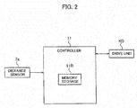
- the respective drive portions controlled by the controller 11 are called as a drive portion KD (see Fig. 2 ) as a whole.
- the drive portion KD includes detectors such as encoders and sensors that detect operating conditions of the respective drive portions. The operating conditions detected by the detectors are fed back to the controller 11.
- the controller 11 is mounted on the floor FL separately from the bending robot 1, and communicates with the bending robot 1 through wires.
- the arm portion A is provided with a distance sensor 7a that can measure a distance to a distance-measured object located below in a contactless manner.
- the distance sensor 7a in the present embodiment is attached to the shoulder 7, and measures a distance by utilizing an optical beam B such as an infrared light or a laser light.
- An installed position and an installed posture of the distance sensor 7a are set so that an optical beam B can be irradiated downward when an optic axis of the optical beam B irradiated for measuring a distance is made perpendicular to the axis line CLd and the axis line CLe and also the axis line CLe is made horizontal.
- the stacker 31 is formed as a cart on which workpieces W can be stacked.
- a stacker placing portion M2a is provided at an upper portion of the stacker placing base M2.
- the stacker 31 is placed on the stacker placing portion M2a while being inclined with an angle ⁇ a to the horizontality so as to its side near the bending robot 1 is positioned lower.
- the stacker placing portion M2a has a stopper S that protrudes upward and determines a rear-side position of the stacker 31 by contacting with the stacker 31.
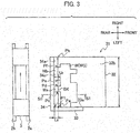
- Fig. 3 is a plan view of the stacker 31 viewed from a direction along an arrow Ya in Fig. 1 , and a workpiece(s) W having a certain shape is stacked on the stacker 31.
- the stacker 31 includes a rectangular-shaped bottom plate 32, a left wall plate 33 and a rear wall plate 34.
- the bottom plate 32 has plural casters 32a (see Fig. 1 ).
- the left wall plate 33 and the rear wall plate 34 are raised from two sides of the bottom plate 32 that are adjacent to each other.
- An upper face 32b of the bottom plate 32, a right face 33a of the left wall plate 33 and a front face (storage reference flat plane) 34a of the rear wall plate 34 are formed as faces that intersect perpendicularly with each other.
- the front face 34a is set so as to be parallel to the guide rails 2a and 2b when the stacker 31 is positioned at the predetermined position where it is restricted by the stopper S.
- the main body 3 moves parallel to the front face 34a.
- the stacker 31 is placed obliquely on the stacker placing portion M2a so that its side near the rear wall plate 34 is positioned lower.
- Workpieces W are placed on the stacker 31 while serving an intersection point of the upper face 32a of the bottom plate 32, the right face 33a of the left wall plate 33 and the front face 34a of the rear wall plate 34 as a placement reference point P1.
- a workpiece(s) W is placed on the stacker 31 while being made closer to the reference point P1 in the present embodiment. Therefore, a workpiece(s) is placed on the stacker 31 so that its at least one portion contacts with the right face 33a of the left wall plate 33 and its at least another portion contacts with the front face 34a of the rear wall plate 34.
- the right face 33a serves as a reference plane in the left-to-right direction
- the front face 34a serves as a reference plane in the front-to-rear direction.
- a length of a workpiece(s) W along the left-to-right direction is shorter than a width L (see Fig. 3 ) of the bottom plate 32.
- the upper face 32a is exposed in the vicinity of the front face 34a. According to this, the upper face 32a of the bottom plate 32 is exposed as a distance measurement reference plane on an irradiation path BK of the after-explained optical beam B.
- the upper face 32a may not be necessarily exposed in a state where a workpiece W is placed thereon.
- a given electric current value is preliminarily set (adjusted) as a reference electric current value that corresponds to a reference position in a height direction during a calibration of the distance sensor 7a in a test operation or the like.
- a height of stacked workpieces W can be measured based on a difference between the set reference electric current value and a measured electric current value or a difference between an absolute value of the set reference electric current value and an absolute value of a measured electric current value.
- the height can be measured based not on an output electric current but on an output electric voltage.
- the mount position and the inclined angle ⁇ of the stacker placing base M2 with respect to the mount position of the bending robot 1 are preliminarily determined.
- the placing position of the stacker 31 on the stacker placing base M2 is also preliminarily determined. Therefore, a position and a direction of the reference point P1 with respect to the bending robot 1 and a placement angle and an inclination direction of a workpiece(s) W placed on the stacker 31 can be preliminarily set, for example, on a three-dimensional coordinate (upper, lower, front, rear, left and right) recited in Fig. 1 . These preliminarily set values are stored in a memory storage 11R of the controller 11.
- the movable area of the arm portion A and the position of the stacker 31 on the stacker placing base M2 are set so that a distance to a rear portion (the rear wall plate 34 and its vicinity) of the stacker 31 can be measured.
- the bending robot 1 detects whether or not a workpiece(s) W is placed on the stacker 31 by the controller 11 when taking out a workpiece(s) W from the stacker 31, and detects a stack height Ha (if a workpiece(s) W is placed) (hereinafter, this is called as a workpiece detection operation).
- the stack height Ha corresponds to (a thickness Wt of a workpiece W) x (the number N of stacked workpieces W).
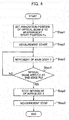
- the measurement operation will be explained with reference to Fig. 4 and Fig. 5 .
- the controller 11 operates the drive portion KD to control a posture of the arm portion A so that the optical beam B is irradiated so as to intersect perpendicularly with the upper face 32a of the bottom plate and irradiated onto a measurement start point Pa (see Fig. 3 ) (Step 1).
- the measurement start point Pa is a point distanced from the reference point P1 toward a front side by a distance La along the upper face 32a.
- the controller 11 starts recording of an output signal (e.g. an electric current value) from the distance sensor 7a (measurement start: Step 2), and moves the main body 3 (moves it straight) in the right direction on the guide rails 2a and 2b (Step 3). Due to this rightward movement of the main body 3, an irradiation position of the optical beam B moves on the irradiation path BK parallel-to and near the front face 34a of the rear wall plate 34 (see Fig. 3 ).
- an output signal e.g. an electric current value
- the controller 11 judges whether or not the irradiation position of the optical beam B arrives at an right end Pb of the bottom plate 32 (Step S4).
- the displacement (position) of the optical beam B is known from the displacement (position) of the main body 3.
- Step 4 If the judgement of the Step 4 is negative (No), a control flow returns to the Step 3 and the movement of the main body 3 is continued. On the other hand, if the judgement of the Step 4 is positive (Yes), the movement of the main body 3 is stopped (Step 5) and the record of the output signal is also stopped to finish the measurement (Step 6). Namely, the measurement operation is finished.
- data shown in Fig. 5 can be obtained by the workpiece detection operation (an output electric current value of the distance sensor 7a).
- the workpiece(s) shown in Fig. 3 has two protruded portions Wa and Wb that contact with the front face 34a of the rear wall plate 34.
- a distance between the distance sensor 7a and a distance-measured object on the irradiation path BK becomes shorter in a segment Pc-Pd where the optical beam B is irradiated onto the protruded portion Wa and a segment Pe-Pf where the optical beam B is irradiated onto the protruded portion Wb than other segments (where the optical beam B is irradiated onto the upper face 32a).
- a segment Pc-Pd where the optical beam B is irradiated onto the protruded portion Wa
- a segment Pe-Pf where the optical beam B is irradiated onto the protruded portion Wb than other segments (where the optical beam B is irradiated onto the upper face 32a).
- the output electric current of the distance sensor 7a in the segment Pc-Pd and the segment Pe-Pf indicates a higher electric current value Ib corresponding to a shorter distance by the height Ha of stacked workpieces W than an electric current value Ia corresponding to a reference distance when the optical beam B is irradiated onto the upper face 32a.
- Relationship between a thickness Wt of one workpiece W and an output electric current value of the distance sensor 7a that corresponds to the thickness Wt is preliminarily stored in the memory storage 11R as a table. Therefore, the controller 11 can judge whether or not a workpiece(s) W is places on the stacker 31 by determining whether or not two electric current values are detected. In addition, the number of stacked workpieces W can be known from a difference of the two electric current values when the two electric current values are detected. In the present embodiment, an electric current value corresponding to a thickness Wt of one workpiece W is Ic.
- the controller 11 judges, based on the measurement result got from the measurement operation, whether or not only one electric current value is measured between the measurement start point Pa and the end Pb (Step 11). If the judgement of the Step 11 is positive (Yes), it is judged that no workpiece W is placed (Step 12) and then a signal indicating "non-placement" is output (Step 13) to finish the judgement operation.
- Step 14 it is judged whether or not three or more electric current values are measured. Since a workpiece(s) W is a flat plate material in the present embodiment, three or more electric current values could not be measured as long as workpieces W are stacked correctly. Therefore, if the judgement of the Step 14 is positive (Yes), it is judged as a placement failure (Step 15) and an alarm is output (Step 16) to finish the judgement operation. On the other hand, if the judgement of the Step 14 is negative (No) (i.e. in a case where two electric current values are measured), it is judged that workpieces W are correctly placed (Step 17).
- the number N of the stacked workpieces W is calculated by dividing the difference (Ib-Ia) of the two electric current values by the electric current value Ic corresponding to the thickness Wt of one workpiece W (Step 18).
- the calculated number N is output (Step 19), and then the judgement operation is finished. In these manners, the workpiece detection operation (the measurement operation and the judgement operation) is completed.
- the controller 11 takes out, for the bending machine M, a workpiece W placed on the stacker 31 by controlling the arm portion A.
- the controller 11 keeps the stack height Ha, the controller 11 moves the end arm 10 at high speed to an upper position distanced from an uppermost workpiece W by a predetermined distance (e.g. 15mm) and then moves the end arm 10 at low speed.
- the controller 11 may retrieve a cut-in distance (corresponding to a distance Lb in Fig. 3 ) of a cutout having a smallest distance from the outline based on the information of the shape and then may set the distance La to a value smaller than the cut-in distance Lb.
- the distance sensor 7a for judging whether or not a workpiece(s) W is placed on the stacker 31 is provided in the arm portion A, and it is possible to measure a distance to a distance-measured object (workpiece W) on a lower side from the arm portion A. Therefore, the arm portion A never interferes with the measurement area of the distance sensor 7a while measuring a distance to the stacker 31 on the lower side from the arm portion A, so that the judgment of workpiece existence or non-existence (judgement whether or not a workpiece W is stored on the stacker 31) can be done in a short time. As a result, bending can be done with high efficiency.
- the present invention is not limited to the above embodiment (processes and configurations), and can be modified within a scope that doesn't deviate from the subject matter of the present invention.
- the measurement operation and the judgement operation may be done concurrently. Specifically, it may be judged that a workpiece(s) is placed (the judgement operation) at a time when two electric current values are detected as shown in Fig. 7 during the measurement operation. In this case, the workpiece detection operation (the measurement operation and the judgement operation) may be completed by stopping the measurement operation even though the optical beam B doesn't yet arrived at the end Pb. In addition, it is not always true that these two electric current values are detected in an order as shown in Fig. 7 i.e. the low electric current value Ia corresponding to the upper face 32a of the bottom plate 32 and then the high electric current value Ib corresponding to the height Ha of workpieces W.
- the workpiece detection operation can be carried out at higher speed.
- the above-explained electric current value Ia is set in the measurement operation by serving the upper face 32a of the bottom plate 32 as the distance measurement reference plane.
- another plane may be set as the distance measurement reference plane.
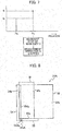
- a stacker 31A shown in Fig. 8 may be used instead of the above-explained stacker 31.
- a (distance measurement) reference plane 31Aa whose height from the upper face 32a is set with high accuracy is provided on an upper end face of the left wall plate 33.
- the optical beam B is irradiated along an irradiation path BKa of which start position is a point PaA on the reference plane 31Aa.
- placement or non-placement of a workpiece(s) W can be judged even when a workpiece W has a large rectangular shape having no cutout and spreading out from the bottom plate 32 as shown in Fig. 8 .
- magnitudes of the electric current values output from the distance sensor 7a are relatively compared with each other.
- the judgement may be done based on an absolute value(s) of the electric current value(s) output from the distance sensor 7a.
- a distance(s) to a distance-measurement object and an absolute value(s) of an electric current value(s) are preliminarily corresponded to each other during a calibration of the distance sensor 7a.
- These correspondences are stored as a correspondence table in the memory storage 11R.
- an effective measuring range of the distance sensor 7a is set as a distance Da to Db along a direction of the optical beam B irradiated from the distance sensor 7a.
- This range is set slightly narrower than a measurement range of specification of the distance sensor 7a.
- the measurement is carried out by irradiating the optical beam B along the irradiation path BA shown in Fig. 3 , for example.
- Fig. 9 shows a flowchart of the judgement operation based on an absolute value.
- a Vsen is a distance to a distance-not-measured object retrieved from the correspondence table stored in the memory storage 11R based on an absolute value of an output electric current of the distance sensor 7a.
- a Vmin is a distance closest to the distance sensor 7a in the distance Vsen on the irradiation path BA after the measurement is started (i.e. a minimum value of the measured distance Vsen is Vmin).
- the Vmin is reset (Step 31) for a new measurement, and then a measurement search operation is started (Step 32). For example, the Vmin is reset to its maximum value (farthest distance: 700mm) in the Step 31.
- Step 33 it is confirmed whether or not a measurement execution command is generated (Step 33). If no measurement execution command is generated (No), the search operation is finished (Step 38), and the Vmin at the time point is output (Step 39) to finish the measurement operation. On the other hand, if a measurement execution command is generated (Yes), it is judged whether or not the measured Vsen stays within the effective measuring range, i.e. whether or not Da ⁇ Vsen ⁇ Db is satisfied (Step 34).
- Step 34 If the Step 34 is negative (No), it is assumed that measurement is hard to be carried out due to setting failure, placement failure of a workpiece(s) or the like. Therefore, an alarm is output (Step 35) and then the measurement operation is finished. If the Step 34 is positive (Yes), the measurement is maintained, and it is judged whether or not a value of the Vsen is smaller than the Vmin (Step 36).
- Step 36 If the Step 36 is negative (No), the control flow returns to the Step 33. On the other hand, if the Step 36 is positive (Yes), the Vmin is overwritten by the measured Vsen to update the measured value (Step 37). After the Step 37, the control flow returns to the Step 33.
- a distance to the distance-not-measured object from the distance sensor 7a can be measured based on the absolute value of the output electric current of the distance sensor 7a. Therefore, an uneven state on the irradiation path BA is recognized and placement or non-placement of a workpiece(s) W can be judged.
- an absolute value of an output electric current corresponding to one workpiece W can be known preliminarily, the number of stacked workpieces W can be also judged.
- the mount location of the controller 11 is not limited.
- the controller 11 may be integrated within the bending robot 1.
- the controller 11 may communicate with the bending robot 1 wirelessly by providing a wireless communication means in the bending robot 1.
- the first aspect of the present invention may be also defined as below.
- the second aspect of the present invention may be also defined as below.
Landscapes
- Engineering & Computer Science (AREA)
- Mechanical Engineering (AREA)
- Robotics (AREA)
- Human Computer Interaction (AREA)
- Manipulator (AREA)
- Bending Of Plates, Rods, And Pipes (AREA)
Abstract
Description
- The present invention relates to a bending robot that takes out a plate-shaped workpiece placed on a stacker (workpiece stacking apparatus) and then supplies it to a bending machine, and relates to a method for detecting existence or non-existence of a workpiece on a stacker.
- A Patent Document 1 listed below discloses a multi-joint robot arm so-called as a bending robot that takes out a plate-shaped workpiece placed on a stacker by suctioning or the like and then supplies it to a bending process at a bending machine. In addition, a
Patent Document 2 listed below discloses a technology in which workpiece detection carried out when taking out one workpiece from stacked workpieces by a multi-joint robot arm is made based on an image(s) taken by a camera disposed above. In addition, aPatent Document 3 listed below discloses a technology in which, in order to suction an uppermost one of stacked plate-shaped workpieces and then convey it, detection of an uppermost position of the stacked workpieces is carried out by a non-contact type distance sensor, using a laser or the like, that is attached to a hanging bracket disposed above the workpieces. -
- Patent Document 1: Japanese Patent Application Publication No.
2002-137019 - Patent Document 2: Japanese Patent Application Publication No.
2012-024903 - Patent Document 3: Japanese Patent Application Publication No.
H5-212475 - It becomes possible to detect existence or non-existence of a workpiece(s) on a stacker by combining the detection technology based on an image(s) disclosed in the
Patent Document 2 or the detection technology based on a result of measuring a distance by a non-contact type distance sensor disclosed in thePatent Document 3 with the bending robot discloses in the Patent Document 1. The detection of existence or non-existence of a workpiece(s) on a stacker is needed to be done first for bending, and is desired to be carried out at speed as high as possible in order to improve efficiency of bending by use of a bending robot. - However, in a case of taking an image(s) or measuring a distance from above a stacker in order to detect existence or non-existence of a workpiece(s), it is needed to carry out operations that have no direct relation to bending, i.e. to evacuate a bending robot from an image-taking area or a distance-measuring area in order not to interfere with the area, and then resume it after image-taking or distance-measuring is finished. Therefore, there is a problem to be improved, i.e. efficiency degradation of bending.
- An object of the present invention is to provide a bending robot and a method for detecting a workpiece that can carry out bending with high efficiency.
- A first aspect of the present invention provides a bending robot that takes out a workpiece that is stored on a stacker having a storage reference flat plane and whose end face is being contacted with the storage reference flat plane, and then supplies the workpiece to a mending machine, comprising: a main body that is movable parallel to the storage reference flat plane; an arm portion that is supported by the main body and capable of positioning above the stacker; and a distance sensor that is provided in the arm portion and capable of measuring a distance to the workpiece stored on the stacker in a contactless manner.
- Here, it is preferable that the main body moves parallel to the storage reference flat plane and the distance sensor measures on a measurement path in a vicinity of the storage reference flat plane.
- A first aspect of the present invention provides a method for detecting whether or not a workpiece is stored on a stacker that stores the workpiece to be supplied to a bending machine by a bending robot, the method comprising: providing, in the stacker, a wall plate that has a storage reference flat plane contacting with an end face of the workpiece stored; preliminarily providing, in the bending robot, a main body that is movable parallel to the storage reference flat plane, an arm portion that is supported by the main body and capable of positioning above the stacker, and a distance sensor that is provided in the arm portion and capable of measuring a distance to the workpiece stored on the stacker in a contactless manner; a distance-measurement step for moving the main body parallel to the storage reference flat plane and measuring a distance along a measurement path in a vicinity of the storage reference flat plane by the distance sensor; and a judgement step for judging that the workpiece is stored on the stacker when two electric current values are measured in the distance-measurement of the distance-measurement step.
-
- [
Fig. 1 ] It is a side view of a bending robot according to an embodiment. - [
Fig. 2 ] It is a block diagram of the bending robot. - [
Fig. 3 ] It is a plan view of a stacker on which workpieces to be held by the bending robot are placed. - [
Fig. 4 ] It is a flowchart of a measurement operation in a workpiece detection operation. - [
Fig. 5 ] It is a graph showing an example of changes of an electric current got through the measurement operation. - [
Fig. 6 ] It is a flowchart of a judgement operation in the workpiece detection operation. - [
Fig. 7 ] It is a graph of a modified example of the judgement operation. - [
Fig. 8 ] It is a plan view of a modified example of the workpiece detection operation. - [
Fig. 9 ] It is a flowchart of another judgement operation. - A bending robot 1 according to an embodiment will be described with reference to the drawings. The bending robot 1 is configured to include a so-called 6-axis vertical multi-joint robot arm. An overall configuration of the bending robot 1 will be explained with reference to
Fig. 1 . For convenience of the explanations, upper, lower, front and rear directions are recited as shown by arrows inFig. 1 . In addition, directions vertical to the drawings are recited as left and right directions, and its frontward direction is the left direction. In addition to the bending robot 1, devices and so on that are mounted around it are shown inFig. 1 . - The bending robot 1 is mounted in-front-of and near a bending machine M. The bending machine M extends in the left-to-right direction. The bending machine M includes a pair of bending dies, and also includes an upper table to which one die Ma thereof is installed and a lower table Md that is disposed oppositely-to and below the upper table Mb and to which another die Mc thereof is installed. The bending machine M makes one of the tables close to the other of the tables, and thereby carries out bending by nipping a workpiece W inserted between the upper table Mb and the lower table Md by a pair of the dies Ma and Mc.
- A stacker placing base M2 is mounted in front of the bending robot 1. A
stacker 31 is placed on the stacker placing base M2. Workpieces W to be bent by the bending machine M can be stacked on thestacker 31. Thestacker 31 can be loaded onto the stacker placing base M2, and can be unloaded from the stacker placing base M2. - The bending robot 1 includes a
base 2 and amain body 3. Thebase 2 has a pair ofguide rails main body 3 is supported by theguide rails - A base arm 4 is attached to the
main body 3. The base arm 4 is rotatable about a vertical axis line CLa (see an arrow Da), and rotatable about a horizontal axis line CLb (see an arrow Db). An end of the base arm 4 is coupled with one end of anintermediate arm 5 by ajoint 6. At thejoint 6, the base arm 4 and theintermediate arm 5 are coupled with each other so as to be rotatable relatively to one another about a horizontal axis line CLc (see an arrow Dc). - Another end of the
intermediate arm 5 is coupled with the shoulder 7 by ajoint 8. At thejoint 8, theintermediate arm 5 and the shoulder 7 are coupled with each other so as to be rotatable relatively to one another about a horizontal axis line CLd (see an arrow Dd). The axis line CLb, the axis line CLc and the axis line CLd are parallel to each other. - The shoulder 7 supports one end of a
straight arm 9 extending straight along an axis line CLe that is perpendicular to the axis line CLd. Another end of thestraight arm 9 supports anend arm 10. Theend arm 10 is rotatable about an axis line CLf that intersects perpendicularly with the axis line CLe (see an arrow Df). Theend arm 10 includes a suctioningportion 10a that suctions a workpiece W to hold it. The suctioningportion 10a is part of aclamper 10b. Theclamper 10b clamps a workpiece W in a thickness direction thereof by its opening and closing operations. The suctioningportion 10a and theclamper 10b are rotatable about an axis line CLg extending in a longitudinal direction of the end arm 10 (see an arrow Dg). - In following explanations, the base arm 4, the
intermediate arm 5, the shoulder 7, thestraight arm 9 and theend arm 10 are called as an arm portion A as a whole. The arm portion A can take various postures by an after-explained drive portion KD, and can be positioned above thestacker 31. In this positioning, thestacker 31 is included at least in a movable area of the shoulder 7 when being viewed from above. - The bending robot 1 takes out a plate-shaped workpiece W stacked on the
stacker 31, and then supplies it to the bending machine M mounted on an opposite side. Specifically, the bending robot 1 takes out an uppermost workpiece W from a workpiece group WG composed of plural workpieces W stacked on thestacker 31 by thesuctioning portion 10a, and supplies the suctioned workpiece W to the bending machine M. The bending robot 1 changes holding positions of the workpiece W by theclamper 10b during a bending process to keep holding of the workpiece W by the posture of the arm portion A so as to follow a shape change of the workpiece W caused by bending. The bending robot 1 ejects (moves) the workpiece W to a predetermined ejection location after the bending. - Movement operations of the
main body 3 on theguide rails controller 11. Here, the respective drive portions controlled by thecontroller 11 are called as a drive portion KD (seeFig. 2 ) as a whole. The drive portion KD includes detectors such as encoders and sensors that detect operating conditions of the respective drive portions. The operating conditions detected by the detectors are fed back to thecontroller 11. InFig. 1 , thecontroller 11 is mounted on the floor FL separately from the bending robot 1, and communicates with the bending robot 1 through wires. - The arm portion A is provided with a
distance sensor 7a that can measure a distance to a distance-measured object located below in a contactless manner. Thedistance sensor 7a in the present embodiment is attached to the shoulder 7, and measures a distance by utilizing an optical beam B such as an infrared light or a laser light. An installed position and an installed posture of thedistance sensor 7a are set so that an optical beam B can be irradiated downward when an optic axis of the optical beam B irradiated for measuring a distance is made perpendicular to the axis line CLd and the axis line CLe and also the axis line CLe is made horizontal. - The
stacker 31 is formed as a cart on which workpieces W can be stacked. A stacker placing portion M2a is provided at an upper portion of the stacker placing base M2. Thestacker 31 is placed on the stacker placing portion M2a while being inclined with an angle θa to the horizontality so as to its side near the bending robot 1 is positioned lower. The stacker placing portion M2a has a stopper S that protrudes upward and determines a rear-side position of thestacker 31 by contacting with thestacker 31.Fig. 3 is a plan view of thestacker 31 viewed from a direction along an arrow Ya inFig. 1 , and a workpiece(s) W having a certain shape is stacked on thestacker 31. - The
stacker 31 includes a rectangular-shapedbottom plate 32, aleft wall plate 33 and arear wall plate 34. Thebottom plate 32 hasplural casters 32a (seeFig. 1 ). Theleft wall plate 33 and therear wall plate 34 are raised from two sides of thebottom plate 32 that are adjacent to each other. Anupper face 32b of thebottom plate 32, aright face 33a of theleft wall plate 33 and a front face (storage reference flat plane) 34a of therear wall plate 34 are formed as faces that intersect perpendicularly with each other. Thefront face 34a is set so as to be parallel to theguide rails stacker 31 is positioned at the predetermined position where it is restricted by the stopper S. Namely, themain body 3 moves parallel to thefront face 34a. Thestacker 31 is placed obliquely on the stacker placing portion M2a so that its side near therear wall plate 34 is positioned lower. Workpieces W are placed on thestacker 31 while serving an intersection point of theupper face 32a of thebottom plate 32, theright face 33a of theleft wall plate 33 and thefront face 34a of therear wall plate 34 as a placement reference point P1. - Although an outline shape of a workpiece W may vary, a workpiece(s) W is placed on the
stacker 31 while being made closer to the reference point P1 in the present embodiment. Therefore, a workpiece(s) is placed on thestacker 31 so that its at least one portion contacts with theright face 33a of theleft wall plate 33 and its at least another portion contacts with thefront face 34a of therear wall plate 34. Namely, theright face 33a serves as a reference plane in the left-to-right direction and thefront face 34a serves as a reference plane in the front-to-rear direction. In addition, it is preferable that, in the vicinity of thefront face 34a, a length of a workpiece(s) W along the left-to-right direction is shorter than a width L (seeFig. 3 ) of thebottom plate 32. Namely, it is preferable that theupper face 32a is exposed in the vicinity of thefront face 34a. According to this, theupper face 32a of thebottom plate 32 is exposed as a distance measurement reference plane on an irradiation path BK of the after-explained optical beam B. - Note that the
upper face 32a may not be necessarily exposed in a state where a workpiece W is placed thereon. In a case where theupper face 32a is not exposed, a given electric current value is preliminarily set (adjusted) as a reference electric current value that corresponds to a reference position in a height direction during a calibration of thedistance sensor 7a in a test operation or the like. According to this, a height of stacked workpieces W can be measured based on a difference between the set reference electric current value and a measured electric current value or a difference between an absolute value of the set reference electric current value and an absolute value of a measured electric current value. Of course, in a case where a measurement output of thedistance sensor 7a is dependent on an electric voltage, the height can be measured based not on an output electric current but on an output electric voltage. - The mount position and the inclined angle θ of the stacker placing base M2 with respect to the mount position of the bending robot 1 are preliminarily determined. In addition, the placing position of the
stacker 31 on the stacker placing base M2 is also preliminarily determined. Therefore, a position and a direction of the reference point P1 with respect to the bending robot 1 and a placement angle and an inclination direction of a workpiece(s) W placed on thestacker 31 can be preliminarily set, for example, on a three-dimensional coordinate (upper, lower, front, rear, left and right) recited inFig. 1 . These preliminarily set values are stored in amemory storage 11R of thecontroller 11. - The movable area of the arm portion A and the position of the
stacker 31 on the stacker placing base M2 are set so that a distance to a rear portion (therear wall plate 34 and its vicinity) of thestacker 31 can be measured. - The bending robot 1 having the above-explained configuration detects whether or not a workpiece(s) W is placed on the
stacker 31 by thecontroller 11 when taking out a workpiece(s) W from thestacker 31, and detects a stack height Ha (if a workpiece(s) W is placed) (hereinafter, this is called as a workpiece detection operation). The stack height Ha corresponds to (a thickness Wt of a workpiece W) x (the number N of stacked workpieces W). - In the workpiece detection operation according to the present embodiment, a measurement operation and a judgement operation are carried out.
- The measurement operation will be explained with reference to
Fig. 4 andFig. 5 . Thecontroller 11 operates the drive portion KD to control a posture of the arm portion A so that the optical beam B is irradiated so as to intersect perpendicularly with theupper face 32a of the bottom plate and irradiated onto a measurement start point Pa (seeFig. 3 ) (Step 1). The measurement start point Pa is a point distanced from the reference point P1 toward a front side by a distance La along theupper face 32a. - The
controller 11 starts recording of an output signal (e.g. an electric current value) from thedistance sensor 7a (measurement start: Step 2), and moves the main body 3 (moves it straight) in the right direction on theguide rails main body 3, an irradiation position of the optical beam B moves on the irradiation path BK parallel-to and near thefront face 34a of the rear wall plate 34 (seeFig. 3 ). - The
controller 11 judges whether or not the irradiation position of the optical beam B arrives at an right end Pb of the bottom plate 32 (Step S4). The displacement (position) of the optical beam B is known from the displacement (position) of themain body 3. - If the judgement of the Step 4 is negative (No), a control flow returns to the
Step 3 and the movement of themain body 3 is continued. On the other hand, if the judgement of the Step 4 is positive (Yes), the movement of themain body 3 is stopped (Step 5) and the record of the output signal is also stopped to finish the measurement (Step 6). Namely, the measurement operation is finished. - For example, in a case where a workpiece(s) has a shape shown in
Fig. 3 , data shown inFig. 5 can be obtained by the workpiece detection operation (an output electric current value of thedistance sensor 7a). The workpiece(s) shown inFig. 3 has two protruded portions Wa and Wb that contact with thefront face 34a of therear wall plate 34. - As shown in
Fig. 3 , a distance between thedistance sensor 7a and a distance-measured object on the irradiation path BK becomes shorter in a segment Pc-Pd where the optical beam B is irradiated onto the protruded portion Wa and a segment Pe-Pf where the optical beam B is irradiated onto the protruded portion Wb than other segments (where the optical beam B is irradiated onto theupper face 32a). Namely, as shown inFig. 5 , the output electric current of thedistance sensor 7a in the segment Pc-Pd and the segment Pe-Pf indicates a higher electric current value Ib corresponding to a shorter distance by the height Ha of stacked workpieces W than an electric current value Ia corresponding to a reference distance when the optical beam B is irradiated onto theupper face 32a. - Relationship between a thickness Wt of one workpiece W and an output electric current value of the
distance sensor 7a that corresponds to the thickness Wt is preliminarily stored in thememory storage 11R as a table. Therefore, thecontroller 11 can judge whether or not a workpiece(s) W is places on thestacker 31 by determining whether or not two electric current values are detected. In addition, the number of stacked workpieces W can be known from a difference of the two electric current values when the two electric current values are detected. In the present embodiment, an electric current value corresponding to a thickness Wt of one workpiece W is Ic. - Next, the judgement will be explained with reference to
Fig. 6 . Thecontroller 11 judges, based on the measurement result got from the measurement operation, whether or not only one electric current value is measured between the measurement start point Pa and the end Pb (Step 11). If the judgement of theStep 11 is positive (Yes), it is judged that no workpiece W is placed (Step 12) and then a signal indicating "non-placement" is output (Step 13) to finish the judgement operation. - On the other hand, if the judgement of the
Step 11 is negative (No), it is judged whether or not three or more electric current values are measured (Step 14). Since a workpiece(s) W is a flat plate material in the present embodiment, three or more electric current values could not be measured as long as workpieces W are stacked correctly. Therefore, if the judgement of the Step 14 is positive (Yes), it is judged as a placement failure (Step 15) and an alarm is output (Step 16) to finish the judgement operation. On the other hand, if the judgement of the Step 14 is negative (No) (i.e. in a case where two electric current values are measured), it is judged that workpieces W are correctly placed (Step 17). - Subsequently to the Step 17, the number N of the stacked workpieces W is calculated by dividing the difference (Ib-Ia) of the two electric current values by the electric current value Ic corresponding to the thickness Wt of one workpiece W (Step 18). The calculated number N is output (Step 19), and then the judgement operation is finished. In these manners, the workpiece detection operation (the measurement operation and the judgement operation) is completed.
- If it is judged in the Step 17 that workpieces W are correctly placed, the
controller 11 takes out, for the bending machine M, a workpiece W placed on thestacker 31 by controlling the arm portion A. Here, since thecontroller 11 keeps the stack height Ha, thecontroller 11 moves theend arm 10 at high speed to an upper position distanced from an uppermost workpiece W by a predetermined distance (e.g. 15mm) and then moves theend arm 10 at low speed. - It is preferable to set the distance La between the reference point P1 and the measurement start point Pa to a value as small as possible (e.g. a value equivalent to the thickness Wt). In the workpiece detection operation, it is not necessary to store information on a shape of a workpiece W and so on in the
memory storage 11R. Therefore, thecontroller 11 never be interrupted by referring to the information on a shape of a workpiece W, and thereby processes can be carried out at a higher speed for that. However, in a case where the information on a shape of a workpiece W is stored in thememory storage 11R for a different purpose, thecontroller 11 may retrieve a cut-in distance (corresponding to a distance Lb inFig. 3 ) of a cutout having a smallest distance from the outline based on the information of the shape and then may set the distance La to a value smaller than the cut-in distance Lb. - According to the above-explained bending robot 1, the
distance sensor 7a for judging whether or not a workpiece(s) W is placed on thestacker 31 is provided in the arm portion A, and it is possible to measure a distance to a distance-measured object (workpiece W) on a lower side from the arm portion A. Therefore, the arm portion A never interferes with the measurement area of thedistance sensor 7a while measuring a distance to thestacker 31 on the lower side from the arm portion A, so that the judgment of workpiece existence or non-existence (judgement whether or not a workpiece W is stored on the stacker 31) can be done in a short time. As a result, bending can be done with high efficiency. - The present invention is not limited to the above embodiment (processes and configurations), and can be modified within a scope that doesn't deviate from the subject matter of the present invention.
- For example, the measurement operation and the judgement operation may be done concurrently. Specifically, it may be judged that a workpiece(s) is placed (the judgement operation) at a time when two electric current values are detected as shown in
Fig. 7 during the measurement operation. In this case, the workpiece detection operation (the measurement operation and the judgement operation) may be completed by stopping the measurement operation even though the optical beam B doesn't yet arrived at the end Pb. In addition, it is not always true that these two electric current values are detected in an order as shown inFig. 7 i.e. the low electric current value Ia corresponding to theupper face 32a of thebottom plate 32 and then the high electric current value Ib corresponding to the height Ha of workpieces W. There may be no cutout at the reference point P1 with a certain shape of a workpiece W, so that and the high electric current value Ib is measured at the measuring start and then the low electric current value Ia is measures while the optical beam B is irradiated onto theupper face 32a through a cutout or the optical beam B is irradiated onto theupper face 32a after passing over an end of the workpiece W. Also in this case, the two electric current values are detected, so that it may be judged that a workpiece (s) W is placed on thestacker 31 and then the workpiece detection operation may be completed. According to this, the workpiece detection operation can be carried out at higher speed. - In the present embodiment, the above-explained electric current value Ia is set in the measurement operation by serving the
upper face 32a of thebottom plate 32 as the distance measurement reference plane. However, another plane may be set as the distance measurement reference plane. For example, astacker 31A shown inFig. 8 may be used instead of the above-explainedstacker 31. In thestacker 31A, a (distance measurement) reference plane 31Aa whose height from theupper face 32a is set with high accuracy is provided on an upper end face of theleft wall plate 33. In the measurement operation, the optical beam B is irradiated along an irradiation path BKa of which start position is a point PaA on the reference plane 31Aa. - When no workpiece W is placed on the
stacker 31, two electric current values corresponding to distances to the reference plane 31Aa and theupper face 32a are measured. On the other hand, when a workpiece(s) W is placed on thestacker 31 and theupper face 32a is not included on the irradiation path BK, two electric current values corresponding to distances to the reference plane 31Aa and an upper face Wc of the workpiece(s) W are measured. Since an electric current value corresponding to the upper face Wc is different from the electric current value corresponding to theupper face 32a, it is detected that the workpiece (s) W is placed on thestacker 31. In addition, when a workpiece (s) W is placed on thestacker 31 and theupper face 32a is not included on the irradiation path BK according to a shape (cutout) of the workpiece(s) W, three electric current values corresponding to distances to the reference plane 31Aa, the upper face Wc of the workpiece (s) W and theupper face 32a are measured. In this case, it is detected that the workpiece(s) W is placed on thestacker 31 without the need to compare the electric current values with each other. - According to the method with providing the reference plane 31Aa, placement or non-placement of a workpiece(s) W can be judged even when a workpiece W has a large rectangular shape having no cutout and spreading out from the
bottom plate 32 as shown inFig. 8 . - In the above-explained judgement operation, magnitudes of the electric current values output from the
distance sensor 7a are relatively compared with each other. However, the judgement may be done based on an absolute value(s) of the electric current value(s) output from thedistance sensor 7a. In this case, a distance(s) to a distance-measurement object and an absolute value(s) of an electric current value(s) are preliminarily corresponded to each other during a calibration of thedistance sensor 7a. These correspondences are stored as a correspondence table in thememory storage 11R. In addition, an effective measuring range of thedistance sensor 7a is set as a distance Da to Db along a direction of the optical beam B irradiated from thedistance sensor 7a. This range is set slightly narrower than a measurement range of specification of thedistance sensor 7a. For example, when a measurement range of specification of thedistance sensor 7a is 250mm to 750mm, the effective measuring range is set as Da=300mm to Db=700mm for some reasons such as accuracy maintenance and so on. Under these preconditions, the measurement is carried out by irradiating the optical beam B along the irradiation path BA shown inFig. 3 , for example. -
Fig. 9 shows a flowchart of the judgement operation based on an absolute value. A Vsen is a distance to a distance-not-measured object retrieved from the correspondence table stored in thememory storage 11R based on an absolute value of an output electric current of thedistance sensor 7a. A Vmin is a distance closest to thedistance sensor 7a in the distance Vsen on the irradiation path BA after the measurement is started (i.e. a minimum value of the measured distance Vsen is Vmin). First, the Vmin is reset (Step 31) for a new measurement, and then a measurement search operation is started (Step 32). For example, the Vmin is reset to its maximum value (farthest distance: 700mm) in theStep 31. - Subsequently, it is confirmed whether or not a measurement execution command is generated (Step 33). If no measurement execution command is generated (No), the search operation is finished (Step 38), and the Vmin at the time point is output (Step 39) to finish the measurement operation. On the other hand, if a measurement execution command is generated (Yes), it is judged whether or not the measured Vsen stays within the effective measuring range, i.e. whether or not Da < Vsen < Db is satisfied (Step 34).
- If the
Step 34 is negative (No), it is assumed that measurement is hard to be carried out due to setting failure, placement failure of a workpiece(s) or the like. Therefore, an alarm is output (Step 35) and then the measurement operation is finished. If theStep 34 is positive (Yes), the measurement is maintained, and it is judged whether or not a value of the Vsen is smaller than the Vmin (Step 36). - If the Step 36 is negative (No), the control flow returns to the
Step 33. On the other hand, if the Step 36 is positive (Yes), the Vmin is overwritten by the measured Vsen to update the measured value (Step 37). After the Step 37, the control flow returns to theStep 33. - According to the present modified example, a distance to the distance-not-measured object from the
distance sensor 7a can be measured based on the absolute value of the output electric current of thedistance sensor 7a. Therefore, an uneven state on the irradiation path BA is recognized and placement or non-placement of a workpiece(s) W can be judged. In addition, since an absolute value of an output electric current corresponding to one workpiece W can be known preliminarily, the number of stacked workpieces W can be also judged. - Note that the mount location of the
controller 11 is not limited. Thecontroller 11 may be integrated within the bending robot 1. In addition, thecontroller 11 may communicate with the bending robot 1 wirelessly by providing a wireless communication means in the bending robot 1. - The first aspect of the present invention may be also defined as below.
- 1. A bending robot that takes out a workpiece that is stored on a stacker and whose end face is being contacted with a storage reference flat plane of the stacker, and then supplies the workpiece to a bending machine, comprising:
- a main body that is movable parallel to the storage reference flat plane;
- an arm portion that is supported by the main body and capable of positioning above the stacker; and
- a distance sensor that is provided in the arm portion and measures a distance to the workpiece stored on the stacker in a contactless manner.
- 2. The bending robot according to the above 1, wherein
the distance sensor measures the distance to the workpiece along a measurement path in a vicinity of the storage reference flat plane while the main body moves parallel to the storage reference flat plane. - 3. The bending robot according to the above 1 or 2, further comprising:
- a controller that includes a memory storage that preliminarily stores a distance between the distance sensor and an upper face of a bottom plate of the stacker,
- wherein the controller judges whether or not the workpiece is stored on the stacker based on a comparison of the distance to the workpiece measured by the distance sensor with a distance to the upper face preliminarily stored in the memory storage.
- The second aspect of the present invention may be also defined as below.
- A. A method for detecting whether or not a workpiece to be supplied to a mending machine by a bending robot is stored on a stacker, wherein
the stacker includes a wall plate that has a storage reference flat plane contacting with an end face of the workpiece stored; and
the bending robot includes a main body that is movable parallel to the storage reference flat plane, an arm portion that is supported by the main body and capable of positioning above the stacker, and a distance sensor that is provided in the arm portion and measures a distance to the workpiece stored on the stacker in a contactless manner,
the method comprising:- moving the main body parallel to the storage reference flat plane;
- measuring a distance along a measurement path in a vicinity of the storage reference flat plane by the distance sensor while the main body moves parallel to the storage reference flat plane; and
- judging that the workpiece is stored on the stacker when two types of distances are measured by the distance sensor.
- The entire contents of a Japanese Patent Application No.
2015-30214 (filed February 19, 2015
Claims (3)
- A bending robot that takes out a workpiece that is stored on a stacker having a storage reference flat plane and whose end face is being contacted with the storage reference flat plane, and then supplies the workpiece to a mending machine, comprising:a main body that is movable parallel to the storage reference flat plane;an arm portion that is supported by the main body and capable of positioning above the stacker; anda distance sensor that is provided in the arm portion and capable of measuring a distance to the workpiece stored on the stacker in a contactless manner.
- The bending robot according to claim 1, wherein the main body moves parallel to the storage reference flat plane and the distance sensor measures on a measurement path in a vicinity of the storage reference flat plane.
- A method for detecting whether or not a workpiece is stored on a stacker that stores the workpiece to be supplied to a bending machine by a bending robot, the method comprising:providing, in the stacker, a wall plate that has a storage reference flat plane contacting with an end face of the workpiece stored;preliminarily providing, in the bending robot, a main body that is movable parallel to the storage reference flat plane, an arm portion that is supported by the main body and capable of positioning above the stacker, and a distance sensor that is provided in the arm portion and capable of measuring a distance to the workpiece stored on the stacker in a contactless manner;a distance-measurement step for moving the main body parallel to the storage reference flat plane and measuring a distance along a measurement path in a vicinity of the storage reference flat plane by the distance sensor; anda judgement step for judging that the workpiece is stored on the stacker when two electric current values are measured in the distance-measurement of the distance-measurement step.
Applications Claiming Priority (2)
| Application Number | Priority Date | Filing Date | Title |
|---|---|---|---|
| JP2015030214A JP6019149B2 (en) | 2015-02-19 | 2015-02-19 | Bending robot and workpiece detection method |
| PCT/JP2016/052434 WO2016132845A1 (en) | 2015-02-19 | 2016-01-28 | Bending robot and workpiece detection method |
Publications (3)
| Publication Number | Publication Date |
|---|---|
| EP3260245A1 true EP3260245A1 (en) | 2017-12-27 |
| EP3260245A4 EP3260245A4 (en) | 2018-11-21 |
| EP3260245B1 EP3260245B1 (en) | 2020-05-27 |
Family
ID=56692017
Family Applications (1)
| Application Number | Title | Priority Date | Filing Date |
|---|---|---|---|
| EP16752234.1A Active EP3260245B1 (en) | 2015-02-19 | 2016-01-28 | Bending robot and workpiece detection method |
Country Status (5)
| Country | Link |
|---|---|
| US (1) | US10046378B2 (en) |
| EP (1) | EP3260245B1 (en) |
| JP (1) | JP6019149B2 (en) |
| CN (1) | CN107249830B (en) |
| WO (1) | WO2016132845A1 (en) |
Cited By (1)
| Publication number | Priority date | Publication date | Assignee | Title |
|---|---|---|---|---|
| AT526774A4 (en) * | 2023-03-31 | 2024-07-15 | Trumpf Maschinen Austria Gmbh & Co Kg | Desk for storing a sheet metal workpiece |
Families Citing this family (9)
| Publication number | Priority date | Publication date | Assignee | Title |
|---|---|---|---|---|
| GB2559374B (en) * | 2017-02-03 | 2019-03-20 | Jaguar Land Rover Ltd | Apparatus and method for separating sheet materials |
| US10953446B2 (en) * | 2017-03-16 | 2021-03-23 | Jose Rossi | Apparatus for forming round and flat-oval shaped HVAC ducts |
| CN108405667B (en) * | 2018-01-17 | 2019-11-12 | 南京邮电大学 | An auxiliary bending robot capable of processing two workpieces at the same time |
| JP7134073B2 (en) * | 2018-11-14 | 2022-09-09 | 株式会社ダイフク | Goods loading equipment |
| CN109590355B (en) * | 2019-01-30 | 2020-03-31 | 福建渃博特自动化设备有限公司 | Method and terminal for taking out plate |
| CN111571565A (en) * | 2019-02-18 | 2020-08-25 | 沈阳新松机器人自动化股份有限公司 | Seven-axis industrial robot |
| KR102236415B1 (en) * | 2019-05-21 | 2021-04-06 | 로체 시스템즈(주) | Bending robot |
| CN110788861B (en) * | 2019-11-15 | 2023-06-06 | 上海新时达机器人有限公司 | Robot overturning and bending method and bending robot |
| KR102280711B1 (en) * | 2020-12-11 | 2021-07-22 | (주)성연테크 | a robotic limp equipped with ingress rocks. |
Family Cites Families (15)
| Publication number | Priority date | Publication date | Assignee | Title |
|---|---|---|---|---|
| JPH05212475A (en) | 1992-01-31 | 1993-08-24 | Mazda Motor Corp | Welding and welding material take-out / conveyor device for press working |
| JPH06344033A (en) * | 1993-06-07 | 1994-12-20 | Komatsu Ltd | Press brake robot system |
| JP3616153B2 (en) * | 1995-03-16 | 2005-02-02 | 株式会社アマダ | Work supply device |
| IT1283019B1 (en) * | 1996-05-16 | 1998-04-03 | Salvagnini Italia Spa | MANAGEMENT METHOD OF A WORKING ISLAND INCLUDING A ROBOT SUBJECTED TO A BENDING PRESS FOR PROCESSING SHEETS. |
| JP2002137019A (en) | 2000-10-27 | 2002-05-14 | Amada Co Ltd | Workpiece twisting machine and bending method using it |
| JP2002153929A (en) * | 2000-11-24 | 2002-05-28 | Amada Co Ltd | Work feed apparatus |
| WO2003040841A1 (en) * | 2001-11-09 | 2003-05-15 | Amada Company, Limited | Compound processing system for sheet metal processing |
| AT503916B1 (en) * | 2006-10-20 | 2008-02-15 | Trumpf Maschinen Austria Gmbh | Separating device for a bending press comprises a manipulating unit and a transport support positioned on a support surface via positioning protrusions of the transport support and positioning units having centering holders |
| DE502007005038D1 (en) * | 2007-02-07 | 2010-10-28 | Wafios Ag | bending machine |
| JP4938115B2 (en) | 2010-07-27 | 2012-05-23 | ファナック株式会社 | Work take-out device and work take-out method |
| AT510516B1 (en) * | 2010-09-21 | 2013-10-15 | Trumpf Maschinen Austria Gmbh | MANUFACTURING CELL WITH A COMPONENT TRANSFER DEVICE AND TRANSPORT DEVICE FOR PARTS AND SPACERS |
| JP6008487B2 (en) * | 2011-06-16 | 2016-10-19 | 三菱重工工作機械株式会社 | Machine Tools |
| JP2014046369A (en) * | 2012-08-29 | 2014-03-17 | Amada Co Ltd | Detection system, material removing apparatus, and detection method |
| JP6091826B2 (en) * | 2012-09-25 | 2017-03-08 | 三菱重工業株式会社 | Processing device control device, processing device, and processing data correction method |
| JP6277624B2 (en) | 2013-08-05 | 2018-02-14 | セイコーエプソン株式会社 | Recording device |
-
2015
- 2015-02-19 JP JP2015030214A patent/JP6019149B2/en active Active
-
2016
- 2016-01-28 WO PCT/JP2016/052434 patent/WO2016132845A1/en not_active Ceased
- 2016-01-28 CN CN201680011091.6A patent/CN107249830B/en active Active
- 2016-01-28 US US15/548,559 patent/US10046378B2/en active Active
- 2016-01-28 EP EP16752234.1A patent/EP3260245B1/en active Active
Cited By (2)
| Publication number | Priority date | Publication date | Assignee | Title |
|---|---|---|---|---|
| AT526774A4 (en) * | 2023-03-31 | 2024-07-15 | Trumpf Maschinen Austria Gmbh & Co Kg | Desk for storing a sheet metal workpiece |
| AT526774B1 (en) * | 2023-03-31 | 2024-07-15 | Trumpf Maschinen Austria Gmbh & Co Kg | Desk for storing a sheet metal workpiece |
Also Published As
| Publication number | Publication date |
|---|---|
| JP2016150423A (en) | 2016-08-22 |
| JP6019149B2 (en) | 2016-11-02 |
| US10046378B2 (en) | 2018-08-14 |
| EP3260245A4 (en) | 2018-11-21 |
| CN107249830A (en) | 2017-10-13 |
| US20180015619A1 (en) | 2018-01-18 |
| CN107249830B (en) | 2018-09-25 |
| EP3260245B1 (en) | 2020-05-27 |
| WO2016132845A1 (en) | 2016-08-25 |
Similar Documents
| Publication | Publication Date | Title |
|---|---|---|
| EP3260245B1 (en) | Bending robot and workpiece detection method | |
| US9902066B2 (en) | Apparatus for automated removal of workpieces arranged in a container | |
| CN101801824B (en) | Method and system for destacking tyres by controlling a robot | |
| US20210245954A1 (en) | Cargo handling apparatus and method | |
| JP6710622B2 (en) | Transfer device and transfer method | |
| US9126337B2 (en) | Robot system having a robot for conveying a workpiece | |
| US9665946B2 (en) | Article conveyor system | |
| EP2708333A2 (en) | Robot apparatus for transferring to-be processed objects | |
| JP5196156B2 (en) | Work picking method in bulk picking equipment | |
| US12119249B2 (en) | Conveyance vehicle | |
| JP2015087960A (en) | MOVING BODY, MOVING BODY MOVING METHOD, ROBOT SYSTEM, AND WORKED PRODUCT MANUFACTURING METHOD | |
| WO2011068227A1 (en) | Dual arm robot | |
| US20220203549A1 (en) | Suction pad and deformation measuring device | |
| EP2570242A2 (en) | Robot system | |
| JP7303454B2 (en) | controller | |
| EP4227256A1 (en) | Substrate conveying hand, substrate conveying apparatus, and substrate conveying method | |
| JP6207758B2 (en) | Component mounting apparatus, surface mounter, and suction height position detection method | |
| JP6543110B2 (en) | Screw tightening device | |
| JP5094435B2 (en) | Automatic teaching system | |
| JPH09178418A (en) | Three-dimensional position detecting device and transfer robot using the same | |
| KR102362476B1 (en) | 3d rotary gantry precision positioning system and method therefor | |
| JP4158537B2 (en) | Unmanned cargo handling vehicle | |
| JP4103950B2 (en) | Work posture detection method | |
| CN112996742A (en) | Crane system, crane positioning device and crane positioning method | |
| US8078312B2 (en) | Methods for inserting a part into a storage section of a storage container and insertion tool arrangement |
Legal Events
| Date | Code | Title | Description |
|---|---|---|---|
| STAA | Information on the status of an ep patent application or granted ep patent |
Free format text: STATUS: THE INTERNATIONAL PUBLICATION HAS BEEN MADE |
|
| PUAI | Public reference made under article 153(3) epc to a published international application that has entered the european phase |
Free format text: ORIGINAL CODE: 0009012 |
|
| STAA | Information on the status of an ep patent application or granted ep patent |
Free format text: STATUS: REQUEST FOR EXAMINATION WAS MADE |
|
| 17P | Request for examination filed |
Effective date: 20170915 |
|
| AK | Designated contracting states |
Kind code of ref document: A1 Designated state(s): AL AT BE BG CH CY CZ DE DK EE ES FI FR GB GR HR HU IE IS IT LI LT LU LV MC MK MT NL NO PL PT RO RS SE SI SK SM TR |
|
| AX | Request for extension of the european patent |
Extension state: BA ME |
|
| DAV | Request for validation of the european patent (deleted) | ||
| DAX | Request for extension of the european patent (deleted) | ||
| A4 | Supplementary search report drawn up and despatched |
Effective date: 20181019 |
|
| RIC1 | Information provided on ipc code assigned before grant |
Ipc: B21D 43/24 20060101ALI20181015BHEP Ipc: B21D 43/00 20060101ALI20181015BHEP Ipc: B21D 5/02 20060101ALI20181015BHEP Ipc: B25J 13/08 20060101AFI20181015BHEP |
|
| STAA | Information on the status of an ep patent application or granted ep patent |
Free format text: STATUS: EXAMINATION IS IN PROGRESS |
|
| 17Q | First examination report despatched |
Effective date: 20190717 |
|
| GRAP | Despatch of communication of intention to grant a patent |
Free format text: ORIGINAL CODE: EPIDOSNIGR1 |
|
| STAA | Information on the status of an ep patent application or granted ep patent |
Free format text: STATUS: GRANT OF PATENT IS INTENDED |
|
| INTG | Intention to grant announced |
Effective date: 20200115 |
|
| GRAS | Grant fee paid |
Free format text: ORIGINAL CODE: EPIDOSNIGR3 |
|
| GRAA | (expected) grant |
Free format text: ORIGINAL CODE: 0009210 |
|
| STAA | Information on the status of an ep patent application or granted ep patent |
Free format text: STATUS: THE PATENT HAS BEEN GRANTED |
|
| AK | Designated contracting states |
Kind code of ref document: B1 Designated state(s): AL AT BE BG CH CY CZ DE DK EE ES FI FR GB GR HR HU IE IS IT LI LT LU LV MC MK MT NL NO PL PT RO RS SE SI SK SM TR |
|
| REG | Reference to a national code |
Ref country code: GB Ref legal event code: FG4D |
|
| REG | Reference to a national code |
Ref country code: CH Ref legal event code: EP |
|
| REG | Reference to a national code |
Ref country code: AT Ref legal event code: REF Ref document number: 1274091 Country of ref document: AT Kind code of ref document: T Effective date: 20200615 |
|
| REG | Reference to a national code |
Ref country code: DE Ref legal event code: R096 Ref document number: 602016037077 Country of ref document: DE |
|
| REG | Reference to a national code |
Ref country code: LT Ref legal event code: MG4D |
|
| PG25 | Lapsed in a contracting state [announced via postgrant information from national office to epo] |
Ref country code: FI Free format text: LAPSE BECAUSE OF FAILURE TO SUBMIT A TRANSLATION OF THE DESCRIPTION OR TO PAY THE FEE WITHIN THE PRESCRIBED TIME-LIMIT Effective date: 20200527 Ref country code: NO Free format text: LAPSE BECAUSE OF FAILURE TO SUBMIT A TRANSLATION OF THE DESCRIPTION OR TO PAY THE FEE WITHIN THE PRESCRIBED TIME-LIMIT Effective date: 20200827 Ref country code: GR Free format text: LAPSE BECAUSE OF FAILURE TO SUBMIT A TRANSLATION OF THE DESCRIPTION OR TO PAY THE FEE WITHIN THE PRESCRIBED TIME-LIMIT Effective date: 20200828 Ref country code: IS Free format text: LAPSE BECAUSE OF FAILURE TO SUBMIT A TRANSLATION OF THE DESCRIPTION OR TO PAY THE FEE WITHIN THE PRESCRIBED TIME-LIMIT Effective date: 20200927 Ref country code: PT Free format text: LAPSE BECAUSE OF FAILURE TO SUBMIT A TRANSLATION OF THE DESCRIPTION OR TO PAY THE FEE WITHIN THE PRESCRIBED TIME-LIMIT Effective date: 20200928 Ref country code: LT Free format text: LAPSE BECAUSE OF FAILURE TO SUBMIT A TRANSLATION OF THE DESCRIPTION OR TO PAY THE FEE WITHIN THE PRESCRIBED TIME-LIMIT Effective date: 20200527 Ref country code: SE Free format text: LAPSE BECAUSE OF FAILURE TO SUBMIT A TRANSLATION OF THE DESCRIPTION OR TO PAY THE FEE WITHIN THE PRESCRIBED TIME-LIMIT Effective date: 20200527 |
|
| REG | Reference to a national code |
Ref country code: NL Ref legal event code: MP Effective date: 20200527 |
|
| PG25 | Lapsed in a contracting state [announced via postgrant information from national office to epo] |
Ref country code: LV Free format text: LAPSE BECAUSE OF FAILURE TO SUBMIT A TRANSLATION OF THE DESCRIPTION OR TO PAY THE FEE WITHIN THE PRESCRIBED TIME-LIMIT Effective date: 20200527 Ref country code: RS Free format text: LAPSE BECAUSE OF FAILURE TO SUBMIT A TRANSLATION OF THE DESCRIPTION OR TO PAY THE FEE WITHIN THE PRESCRIBED TIME-LIMIT Effective date: 20200527 Ref country code: HR Free format text: LAPSE BECAUSE OF FAILURE TO SUBMIT A TRANSLATION OF THE DESCRIPTION OR TO PAY THE FEE WITHIN THE PRESCRIBED TIME-LIMIT Effective date: 20200527 Ref country code: BG Free format text: LAPSE BECAUSE OF FAILURE TO SUBMIT A TRANSLATION OF THE DESCRIPTION OR TO PAY THE FEE WITHIN THE PRESCRIBED TIME-LIMIT Effective date: 20200827 |
|
| REG | Reference to a national code |
Ref country code: AT Ref legal event code: MK05 Ref document number: 1274091 Country of ref document: AT Kind code of ref document: T Effective date: 20200527 |
|
| PG25 | Lapsed in a contracting state [announced via postgrant information from national office to epo] |
Ref country code: NL Free format text: LAPSE BECAUSE OF FAILURE TO SUBMIT A TRANSLATION OF THE DESCRIPTION OR TO PAY THE FEE WITHIN THE PRESCRIBED TIME-LIMIT Effective date: 20200527 Ref country code: AL Free format text: LAPSE BECAUSE OF FAILURE TO SUBMIT A TRANSLATION OF THE DESCRIPTION OR TO PAY THE FEE WITHIN THE PRESCRIBED TIME-LIMIT Effective date: 20200527 |
|
| PG25 | Lapsed in a contracting state [announced via postgrant information from national office to epo] |
Ref country code: DK Free format text: LAPSE BECAUSE OF FAILURE TO SUBMIT A TRANSLATION OF THE DESCRIPTION OR TO PAY THE FEE WITHIN THE PRESCRIBED TIME-LIMIT Effective date: 20200527 Ref country code: SM Free format text: LAPSE BECAUSE OF FAILURE TO SUBMIT A TRANSLATION OF THE DESCRIPTION OR TO PAY THE FEE WITHIN THE PRESCRIBED TIME-LIMIT Effective date: 20200527 Ref country code: EE Free format text: LAPSE BECAUSE OF FAILURE TO SUBMIT A TRANSLATION OF THE DESCRIPTION OR TO PAY THE FEE WITHIN THE PRESCRIBED TIME-LIMIT Effective date: 20200527 Ref country code: AT Free format text: LAPSE BECAUSE OF FAILURE TO SUBMIT A TRANSLATION OF THE DESCRIPTION OR TO PAY THE FEE WITHIN THE PRESCRIBED TIME-LIMIT Effective date: 20200527 Ref country code: ES Free format text: LAPSE BECAUSE OF FAILURE TO SUBMIT A TRANSLATION OF THE DESCRIPTION OR TO PAY THE FEE WITHIN THE PRESCRIBED TIME-LIMIT Effective date: 20200527 Ref country code: CZ Free format text: LAPSE BECAUSE OF FAILURE TO SUBMIT A TRANSLATION OF THE DESCRIPTION OR TO PAY THE FEE WITHIN THE PRESCRIBED TIME-LIMIT Effective date: 20200527 Ref country code: RO Free format text: LAPSE BECAUSE OF FAILURE TO SUBMIT A TRANSLATION OF THE DESCRIPTION OR TO PAY THE FEE WITHIN THE PRESCRIBED TIME-LIMIT Effective date: 20200527 |
|
| PG25 | Lapsed in a contracting state [announced via postgrant information from national office to epo] |
Ref country code: PL Free format text: LAPSE BECAUSE OF FAILURE TO SUBMIT A TRANSLATION OF THE DESCRIPTION OR TO PAY THE FEE WITHIN THE PRESCRIBED TIME-LIMIT Effective date: 20200527 Ref country code: SK Free format text: LAPSE BECAUSE OF FAILURE TO SUBMIT A TRANSLATION OF THE DESCRIPTION OR TO PAY THE FEE WITHIN THE PRESCRIBED TIME-LIMIT Effective date: 20200527 |
|
| REG | Reference to a national code |
Ref country code: DE Ref legal event code: R097 Ref document number: 602016037077 Country of ref document: DE |
|
| PLBE | No opposition filed within time limit |
Free format text: ORIGINAL CODE: 0009261 |
|
| STAA | Information on the status of an ep patent application or granted ep patent |
Free format text: STATUS: NO OPPOSITION FILED WITHIN TIME LIMIT |
|
| 26N | No opposition filed |
Effective date: 20210302 |
|
| PG25 | Lapsed in a contracting state [announced via postgrant information from national office to epo] |
Ref country code: SI Free format text: LAPSE BECAUSE OF FAILURE TO SUBMIT A TRANSLATION OF THE DESCRIPTION OR TO PAY THE FEE WITHIN THE PRESCRIBED TIME-LIMIT Effective date: 20200527 |
|
| PG25 | Lapsed in a contracting state [announced via postgrant information from national office to epo] |
Ref country code: MC Free format text: LAPSE BECAUSE OF FAILURE TO SUBMIT A TRANSLATION OF THE DESCRIPTION OR TO PAY THE FEE WITHIN THE PRESCRIBED TIME-LIMIT Effective date: 20200527 |
|
| REG | Reference to a national code |
Ref country code: CH Ref legal event code: PL |
|
| GBPC | Gb: european patent ceased through non-payment of renewal fee |
Effective date: 20210128 |
|
| PG25 | Lapsed in a contracting state [announced via postgrant information from national office to epo] |
Ref country code: LU Free format text: LAPSE BECAUSE OF NON-PAYMENT OF DUE FEES Effective date: 20210128 |
|
| REG | Reference to a national code |
Ref country code: BE Ref legal event code: MM Effective date: 20210131 |
|
| PG25 | Lapsed in a contracting state [announced via postgrant information from national office to epo] |
Ref country code: CH Free format text: LAPSE BECAUSE OF NON-PAYMENT OF DUE FEES Effective date: 20210131 Ref country code: LI Free format text: LAPSE BECAUSE OF NON-PAYMENT OF DUE FEES Effective date: 20210131 Ref country code: GB Free format text: LAPSE BECAUSE OF NON-PAYMENT OF DUE FEES Effective date: 20210128 |
|
| PG25 | Lapsed in a contracting state [announced via postgrant information from national office to epo] |
Ref country code: IE Free format text: LAPSE BECAUSE OF NON-PAYMENT OF DUE FEES Effective date: 20210128 |
|
| PG25 | Lapsed in a contracting state [announced via postgrant information from national office to epo] |
Ref country code: BE Free format text: LAPSE BECAUSE OF NON-PAYMENT OF DUE FEES Effective date: 20210131 |
|
| P01 | Opt-out of the competence of the unified patent court (upc) registered |
Effective date: 20230428 |
|
| PG25 | Lapsed in a contracting state [announced via postgrant information from national office to epo] |
Ref country code: CY Free format text: LAPSE BECAUSE OF FAILURE TO SUBMIT A TRANSLATION OF THE DESCRIPTION OR TO PAY THE FEE WITHIN THE PRESCRIBED TIME-LIMIT Effective date: 20200527 |
|
| PG25 | Lapsed in a contracting state [announced via postgrant information from national office to epo] |
Ref country code: HU Free format text: LAPSE BECAUSE OF FAILURE TO SUBMIT A TRANSLATION OF THE DESCRIPTION OR TO PAY THE FEE WITHIN THE PRESCRIBED TIME-LIMIT; INVALID AB INITIO Effective date: 20160128 |
|
| PG25 | Lapsed in a contracting state [announced via postgrant information from national office to epo] |
Ref country code: MK Free format text: LAPSE BECAUSE OF FAILURE TO SUBMIT A TRANSLATION OF THE DESCRIPTION OR TO PAY THE FEE WITHIN THE PRESCRIBED TIME-LIMIT Effective date: 20200527 |
|
| PG25 | Lapsed in a contracting state [announced via postgrant information from national office to epo] |
Ref country code: MT Free format text: LAPSE BECAUSE OF FAILURE TO SUBMIT A TRANSLATION OF THE DESCRIPTION OR TO PAY THE FEE WITHIN THE PRESCRIBED TIME-LIMIT Effective date: 20200527 |
|
| PGFP | Annual fee paid to national office [announced via postgrant information from national office to epo] |
Ref country code: IT Payment date: 20250129 Year of fee payment: 10 |
|
| PG25 | Lapsed in a contracting state [announced via postgrant information from national office to epo] |
Ref country code: TR Free format text: LAPSE BECAUSE OF FAILURE TO SUBMIT A TRANSLATION OF THE DESCRIPTION OR TO PAY THE FEE WITHIN THE PRESCRIBED TIME-LIMIT Effective date: 20200527 |
|
| PGFP | Annual fee paid to national office [announced via postgrant information from national office to epo] |
Ref country code: DE Payment date: 20260121 Year of fee payment: 11 |
|
| PGFP | Annual fee paid to national office [announced via postgrant information from national office to epo] |
Ref country code: FR Payment date: 20260123 Year of fee payment: 11 |