EP3260224A1 - Hybrid electrostatic 3-d printer using laser fusing - Google Patents
Hybrid electrostatic 3-d printer using laser fusing Download PDFInfo
- Publication number
- EP3260224A1 EP3260224A1 EP17166861.9A EP17166861A EP3260224A1 EP 3260224 A1 EP3260224 A1 EP 3260224A1 EP 17166861 A EP17166861 A EP 17166861A EP 3260224 A1 EP3260224 A1 EP 3260224A1
- Authority
- EP
- European Patent Office
- Prior art keywords
- layer
- station
- platen
- intermediate transfer
- layers
- Prior art date
- Legal status (The legal status is an assumption and is not a legal conclusion. Google has not performed a legal analysis and makes no representation as to the accuracy of the status listed.)
- Granted
Links
Images











Classifications
-
- B—PERFORMING OPERATIONS; TRANSPORTING
- B28—WORKING CEMENT, CLAY, OR STONE
- B28B—SHAPING CLAY OR OTHER CERAMIC COMPOSITIONS; SHAPING SLAG; SHAPING MIXTURES CONTAINING CEMENTITIOUS MATERIAL, e.g. PLASTER
- B28B1/00—Producing shaped prefabricated articles from the material
- B28B1/001—Rapid manufacturing of 3D objects by additive depositing, agglomerating or laminating of material
-
- B—PERFORMING OPERATIONS; TRANSPORTING
- B29—WORKING OF PLASTICS; WORKING OF SUBSTANCES IN A PLASTIC STATE IN GENERAL
- B29C—SHAPING OR JOINING OF PLASTICS; SHAPING OF MATERIAL IN A PLASTIC STATE, NOT OTHERWISE PROVIDED FOR; AFTER-TREATMENT OF THE SHAPED PRODUCTS, e.g. REPAIRING
- B29C64/00—Additive manufacturing, i.e. manufacturing of three-dimensional [3D] objects by additive deposition, additive agglomeration or additive layering, e.g. by 3D printing, stereolithography or selective laser sintering
- B29C64/20—Apparatus for additive manufacturing; Details thereof or accessories therefor
-
- B—PERFORMING OPERATIONS; TRANSPORTING
- B22—CASTING; POWDER METALLURGY
- B22F—WORKING METALLIC POWDER; MANUFACTURE OF ARTICLES FROM METALLIC POWDER; MAKING METALLIC POWDER; APPARATUS OR DEVICES SPECIALLY ADAPTED FOR METALLIC POWDER
- B22F10/00—Additive manufacturing of workpieces or articles from metallic powder
- B22F10/20—Direct sintering or melting
- B22F10/28—Powder bed fusion, e.g. selective laser melting [SLM] or electron beam melting [EBM]
-
- B—PERFORMING OPERATIONS; TRANSPORTING
- B22—CASTING; POWDER METALLURGY
- B22F—WORKING METALLIC POWDER; MANUFACTURE OF ARTICLES FROM METALLIC POWDER; MAKING METALLIC POWDER; APPARATUS OR DEVICES SPECIALLY ADAPTED FOR METALLIC POWDER
- B22F10/00—Additive manufacturing of workpieces or articles from metallic powder
- B22F10/60—Treatment of workpieces or articles after build-up
- B22F10/66—Treatment of workpieces or articles after build-up by mechanical means
-
- B—PERFORMING OPERATIONS; TRANSPORTING
- B22—CASTING; POWDER METALLURGY
- B22F—WORKING METALLIC POWDER; MANUFACTURE OF ARTICLES FROM METALLIC POWDER; MAKING METALLIC POWDER; APPARATUS OR DEVICES SPECIALLY ADAPTED FOR METALLIC POWDER
- B22F10/00—Additive manufacturing of workpieces or articles from metallic powder
- B22F10/60—Treatment of workpieces or articles after build-up
- B22F10/68—Cleaning or washing
-
- B—PERFORMING OPERATIONS; TRANSPORTING
- B22—CASTING; POWDER METALLURGY
- B22F—WORKING METALLIC POWDER; MANUFACTURE OF ARTICLES FROM METALLIC POWDER; MAKING METALLIC POWDER; APPARATUS OR DEVICES SPECIALLY ADAPTED FOR METALLIC POWDER
- B22F12/00—Apparatus or devices specially adapted for additive manufacturing; Auxiliary means for additive manufacturing; Combinations of additive manufacturing apparatus or devices with other processing apparatus or devices
- B22F12/30—Platforms or substrates
- B22F12/33—Platforms or substrates translatory in the deposition plane
-
- B—PERFORMING OPERATIONS; TRANSPORTING
- B22—CASTING; POWDER METALLURGY
- B22F—WORKING METALLIC POWDER; MANUFACTURE OF ARTICLES FROM METALLIC POWDER; MAKING METALLIC POWDER; APPARATUS OR DEVICES SPECIALLY ADAPTED FOR METALLIC POWDER
- B22F12/00—Apparatus or devices specially adapted for additive manufacturing; Auxiliary means for additive manufacturing; Combinations of additive manufacturing apparatus or devices with other processing apparatus or devices
- B22F12/80—Plants, production lines or modules
- B22F12/82—Combination of additive manufacturing apparatus or devices with other processing apparatus or devices
- B22F12/86—Serial processing with multiple devices grouped
-
- B—PERFORMING OPERATIONS; TRANSPORTING
- B29—WORKING OF PLASTICS; WORKING OF SUBSTANCES IN A PLASTIC STATE IN GENERAL
- B29C—SHAPING OR JOINING OF PLASTICS; SHAPING OF MATERIAL IN A PLASTIC STATE, NOT OTHERWISE PROVIDED FOR; AFTER-TREATMENT OF THE SHAPED PRODUCTS, e.g. REPAIRING
- B29C64/00—Additive manufacturing, i.e. manufacturing of three-dimensional [3D] objects by additive deposition, additive agglomeration or additive layering, e.g. by 3D printing, stereolithography or selective laser sintering
- B29C64/10—Processes of additive manufacturing
- B29C64/141—Processes of additive manufacturing using only solid materials
- B29C64/153—Processes of additive manufacturing using only solid materials using layers of powder being selectively joined, e.g. by selective laser sintering or melting
-
- B—PERFORMING OPERATIONS; TRANSPORTING
- B29—WORKING OF PLASTICS; WORKING OF SUBSTANCES IN A PLASTIC STATE IN GENERAL
- B29C—SHAPING OR JOINING OF PLASTICS; SHAPING OF MATERIAL IN A PLASTIC STATE, NOT OTHERWISE PROVIDED FOR; AFTER-TREATMENT OF THE SHAPED PRODUCTS, e.g. REPAIRING
- B29C64/00—Additive manufacturing, i.e. manufacturing of three-dimensional [3D] objects by additive deposition, additive agglomeration or additive layering, e.g. by 3D printing, stereolithography or selective laser sintering
- B29C64/20—Apparatus for additive manufacturing; Details thereof or accessories therefor
- B29C64/205—Means for applying layers
-
- B—PERFORMING OPERATIONS; TRANSPORTING
- B29—WORKING OF PLASTICS; WORKING OF SUBSTANCES IN A PLASTIC STATE IN GENERAL
- B29C—SHAPING OR JOINING OF PLASTICS; SHAPING OF MATERIAL IN A PLASTIC STATE, NOT OTHERWISE PROVIDED FOR; AFTER-TREATMENT OF THE SHAPED PRODUCTS, e.g. REPAIRING
- B29C64/00—Additive manufacturing, i.e. manufacturing of three-dimensional [3D] objects by additive deposition, additive agglomeration or additive layering, e.g. by 3D printing, stereolithography or selective laser sintering
- B29C64/20—Apparatus for additive manufacturing; Details thereof or accessories therefor
- B29C64/205—Means for applying layers
- B29C64/223—Foils or films, e.g. for transferring layers of building material from one working station to another
-
- B—PERFORMING OPERATIONS; TRANSPORTING
- B29—WORKING OF PLASTICS; WORKING OF SUBSTANCES IN A PLASTIC STATE IN GENERAL
- B29C—SHAPING OR JOINING OF PLASTICS; SHAPING OF MATERIAL IN A PLASTIC STATE, NOT OTHERWISE PROVIDED FOR; AFTER-TREATMENT OF THE SHAPED PRODUCTS, e.g. REPAIRING
- B29C64/00—Additive manufacturing, i.e. manufacturing of three-dimensional [3D] objects by additive deposition, additive agglomeration or additive layering, e.g. by 3D printing, stereolithography or selective laser sintering
- B29C64/20—Apparatus for additive manufacturing; Details thereof or accessories therefor
- B29C64/264—Arrangements for irradiation
-
- B—PERFORMING OPERATIONS; TRANSPORTING
- B29—WORKING OF PLASTICS; WORKING OF SUBSTANCES IN A PLASTIC STATE IN GENERAL
- B29C—SHAPING OR JOINING OF PLASTICS; SHAPING OF MATERIAL IN A PLASTIC STATE, NOT OTHERWISE PROVIDED FOR; AFTER-TREATMENT OF THE SHAPED PRODUCTS, e.g. REPAIRING
- B29C64/00—Additive manufacturing, i.e. manufacturing of three-dimensional [3D] objects by additive deposition, additive agglomeration or additive layering, e.g. by 3D printing, stereolithography or selective laser sintering
- B29C64/30—Auxiliary operations or equipment
- B29C64/35—Cleaning
-
- B—PERFORMING OPERATIONS; TRANSPORTING
- B33—ADDITIVE MANUFACTURING TECHNOLOGY
- B33Y—ADDITIVE MANUFACTURING, i.e. MANUFACTURING OF THREE-DIMENSIONAL [3D] OBJECTS BY ADDITIVE DEPOSITION, ADDITIVE AGGLOMERATION OR ADDITIVE LAYERING, e.g. BY 3D PRINTING, STEREOLITHOGRAPHY OR SELECTIVE LASER SINTERING
- B33Y10/00—Processes of additive manufacturing
-
- B—PERFORMING OPERATIONS; TRANSPORTING
- B33—ADDITIVE MANUFACTURING TECHNOLOGY
- B33Y—ADDITIVE MANUFACTURING, i.e. MANUFACTURING OF THREE-DIMENSIONAL [3D] OBJECTS BY ADDITIVE DEPOSITION, ADDITIVE AGGLOMERATION OR ADDITIVE LAYERING, e.g. BY 3D PRINTING, STEREOLITHOGRAPHY OR SELECTIVE LASER SINTERING
- B33Y30/00—Apparatus for additive manufacturing; Details thereof or accessories therefor
-
- B—PERFORMING OPERATIONS; TRANSPORTING
- B33—ADDITIVE MANUFACTURING TECHNOLOGY
- B33Y—ADDITIVE MANUFACTURING, i.e. MANUFACTURING OF THREE-DIMENSIONAL [3D] OBJECTS BY ADDITIVE DEPOSITION, ADDITIVE AGGLOMERATION OR ADDITIVE LAYERING, e.g. BY 3D PRINTING, STEREOLITHOGRAPHY OR SELECTIVE LASER SINTERING
- B33Y40/00—Auxiliary operations or equipment, e.g. for material handling
-
- B—PERFORMING OPERATIONS; TRANSPORTING
- B41—PRINTING; LINING MACHINES; TYPEWRITERS; STAMPS
- B41J—TYPEWRITERS; SELECTIVE PRINTING MECHANISMS, i.e. MECHANISMS PRINTING OTHERWISE THAN FROM A FORME; CORRECTION OF TYPOGRAPHICAL ERRORS
- B41J2/00—Typewriters or selective printing mechanisms characterised by the printing or marking process for which they are designed
- B41J2/435—Typewriters or selective printing mechanisms characterised by the printing or marking process for which they are designed characterised by selective application of radiation to a printing material or impression-transfer material
- B41J2/44—Typewriters or selective printing mechanisms characterised by the printing or marking process for which they are designed characterised by selective application of radiation to a printing material or impression-transfer material using single radiation source per colour, e.g. lighting beams or shutter arrangements
- B41J2/442—Typewriters or selective printing mechanisms characterised by the printing or marking process for which they are designed characterised by selective application of radiation to a printing material or impression-transfer material using single radiation source per colour, e.g. lighting beams or shutter arrangements using lasers
-
- G—PHYSICS
- G03—PHOTOGRAPHY; CINEMATOGRAPHY; ANALOGOUS TECHNIQUES USING WAVES OTHER THAN OPTICAL WAVES; ELECTROGRAPHY; HOLOGRAPHY
- G03G—ELECTROGRAPHY; ELECTROPHOTOGRAPHY; MAGNETOGRAPHY
- G03G15/00—Apparatus for electrographic processes using a charge pattern
- G03G15/14—Apparatus for electrographic processes using a charge pattern for transferring a pattern to a second base
- G03G15/16—Apparatus for electrographic processes using a charge pattern for transferring a pattern to a second base of a toner pattern, e.g. a powder pattern, e.g. magnetic transfer
- G03G15/1625—Apparatus for electrographic processes using a charge pattern for transferring a pattern to a second base of a toner pattern, e.g. a powder pattern, e.g. magnetic transfer on a base other than paper
-
- G—PHYSICS
- G03—PHOTOGRAPHY; CINEMATOGRAPHY; ANALOGOUS TECHNIQUES USING WAVES OTHER THAN OPTICAL WAVES; ELECTROGRAPHY; HOLOGRAPHY
- G03G—ELECTROGRAPHY; ELECTROPHOTOGRAPHY; MAGNETOGRAPHY
- G03G15/00—Apparatus for electrographic processes using a charge pattern
- G03G15/14—Apparatus for electrographic processes using a charge pattern for transferring a pattern to a second base
- G03G15/16—Apparatus for electrographic processes using a charge pattern for transferring a pattern to a second base of a toner pattern, e.g. a powder pattern, e.g. magnetic transfer
- G03G15/1665—Apparatus for electrographic processes using a charge pattern for transferring a pattern to a second base of a toner pattern, e.g. a powder pattern, e.g. magnetic transfer by introducing the second base in the nip formed by the recording member and at least one transfer member, e.g. in combination with bias or heat
-
- G—PHYSICS
- G03—PHOTOGRAPHY; CINEMATOGRAPHY; ANALOGOUS TECHNIQUES USING WAVES OTHER THAN OPTICAL WAVES; ELECTROGRAPHY; HOLOGRAPHY
- G03G—ELECTROGRAPHY; ELECTROPHOTOGRAPHY; MAGNETOGRAPHY
- G03G15/00—Apparatus for electrographic processes using a charge pattern
- G03G15/20—Apparatus for electrographic processes using a charge pattern for fixing, e.g. by using heat
- G03G15/2003—Apparatus for electrographic processes using a charge pattern for fixing, e.g. by using heat using heat
- G03G15/2007—Apparatus for electrographic processes using a charge pattern for fixing, e.g. by using heat using heat using radiant heat, e.g. infrared lamps, microwave heaters
-
- G—PHYSICS
- G03—PHOTOGRAPHY; CINEMATOGRAPHY; ANALOGOUS TECHNIQUES USING WAVES OTHER THAN OPTICAL WAVES; ELECTROGRAPHY; HOLOGRAPHY
- G03G—ELECTROGRAPHY; ELECTROPHOTOGRAPHY; MAGNETOGRAPHY
- G03G15/00—Apparatus for electrographic processes using a charge pattern
- G03G15/22—Apparatus for electrographic processes using a charge pattern involving the combination of more than one step according to groups G03G13/02 - G03G13/20
- G03G15/221—Machines other than electrographic copiers, e.g. electrophotographic cameras, electrostatic typewriters
- G03G15/224—Machines for forming tactile or three dimensional images by electrographic means, e.g. braille, 3d printing
-
- B—PERFORMING OPERATIONS; TRANSPORTING
- B22—CASTING; POWDER METALLURGY
- B22F—WORKING METALLIC POWDER; MANUFACTURE OF ARTICLES FROM METALLIC POWDER; MAKING METALLIC POWDER; APPARATUS OR DEVICES SPECIALLY ADAPTED FOR METALLIC POWDER
- B22F10/00—Additive manufacturing of workpieces or articles from metallic powder
- B22F10/60—Treatment of workpieces or articles after build-up
- B22F10/62—Treatment of workpieces or articles after build-up by chemical means
-
- B—PERFORMING OPERATIONS; TRANSPORTING
- B22—CASTING; POWDER METALLURGY
- B22F—WORKING METALLIC POWDER; MANUFACTURE OF ARTICLES FROM METALLIC POWDER; MAKING METALLIC POWDER; APPARATUS OR DEVICES SPECIALLY ADAPTED FOR METALLIC POWDER
- B22F10/00—Additive manufacturing of workpieces or articles from metallic powder
- B22F10/70—Recycling
- B22F10/73—Recycling of powder
-
- B—PERFORMING OPERATIONS; TRANSPORTING
- B22—CASTING; POWDER METALLURGY
- B22F—WORKING METALLIC POWDER; MANUFACTURE OF ARTICLES FROM METALLIC POWDER; MAKING METALLIC POWDER; APPARATUS OR DEVICES SPECIALLY ADAPTED FOR METALLIC POWDER
- B22F12/00—Apparatus or devices specially adapted for additive manufacturing; Auxiliary means for additive manufacturing; Combinations of additive manufacturing apparatus or devices with other processing apparatus or devices
- B22F12/50—Means for feeding of material, e.g. heads
-
- B—PERFORMING OPERATIONS; TRANSPORTING
- B22—CASTING; POWDER METALLURGY
- B22F—WORKING METALLIC POWDER; MANUFACTURE OF ARTICLES FROM METALLIC POWDER; MAKING METALLIC POWDER; APPARATUS OR DEVICES SPECIALLY ADAPTED FOR METALLIC POWDER
- B22F12/00—Apparatus or devices specially adapted for additive manufacturing; Auxiliary means for additive manufacturing; Combinations of additive manufacturing apparatus or devices with other processing apparatus or devices
- B22F12/50—Means for feeding of material, e.g. heads
- B22F12/55—Two or more means for feeding material
-
- B—PERFORMING OPERATIONS; TRANSPORTING
- B29—WORKING OF PLASTICS; WORKING OF SUBSTANCES IN A PLASTIC STATE IN GENERAL
- B29K—INDEXING SCHEME ASSOCIATED WITH SUBCLASSES B29B, B29C OR B29D, RELATING TO MOULDING MATERIALS OR TO MATERIALS FOR MOULDS, REINFORCEMENTS, FILLERS OR PREFORMED PARTS, e.g. INSERTS
- B29K2105/00—Condition, form or state of moulded material or of the material to be shaped
- B29K2105/25—Solid
- B29K2105/251—Particles, powder or granules
-
- G—PHYSICS
- G03—PHOTOGRAPHY; CINEMATOGRAPHY; ANALOGOUS TECHNIQUES USING WAVES OTHER THAN OPTICAL WAVES; ELECTROGRAPHY; HOLOGRAPHY
- G03G—ELECTROGRAPHY; ELECTROPHOTOGRAPHY; MAGNETOGRAPHY
- G03G2215/00—Apparatus for electrophotographic processes
- G03G2215/16—Transferring device, details
- G03G2215/1676—Simultaneous toner image transfer and fixing
- G03G2215/1695—Simultaneous toner image transfer and fixing at the second or higher order transfer point
-
- Y—GENERAL TAGGING OF NEW TECHNOLOGICAL DEVELOPMENTS; GENERAL TAGGING OF CROSS-SECTIONAL TECHNOLOGIES SPANNING OVER SEVERAL SECTIONS OF THE IPC; TECHNICAL SUBJECTS COVERED BY FORMER USPC CROSS-REFERENCE ART COLLECTIONS [XRACs] AND DIGESTS
- Y02—TECHNOLOGIES OR APPLICATIONS FOR MITIGATION OR ADAPTATION AGAINST CLIMATE CHANGE
- Y02P—CLIMATE CHANGE MITIGATION TECHNOLOGIES IN THE PRODUCTION OR PROCESSING OF GOODS
- Y02P10/00—Technologies related to metal processing
- Y02P10/25—Process efficiency
Definitions
- Systems and methods herein generally relate to three-dimensional (3-D) printing processes that use electrostatic printing processes.
- Three-dimensional printing can produce objects using, for example, ink-jet printers.
- a platform moves below an ink-jet to form a layer of build and support materials, and each layer is hardened using a UV light source. These steps are repeated layer-by-layer.
- Support materials generally comprise acid-, base- or water-soluble polymers, which can be selectively rinsed from the build material after 3-D printing is complete.
- electrostatic (electro-photographic) process is a well-known means of generating two-dimensional digital images, which transfer materials onto an intermediate surface (such as a photoreceptor belt or drum). Advancements in the way an electro-photographic image is transferred can leverage the speed, efficiency and digital nature of printing systems.
- Exemplary three-dimensional (3-D) printers include, among other components, an intermediate transfer surface, development stations positioned to electrostatically transfer different materials to the intermediate transfer surface, and a transfer station adjacent the intermediate transfer surface.
- the transfer station is positioned to receive layers of the different materials as the intermediate transfer surface moves past the transfer station.
- the development stations and the transfer station are positioned relative to the intermediate transfer surface such that a point on the intermediate transfer surface, when the intermediate transfer surface moves in a process direction, first passes the development stations and then passes the transfer station.
- Such structures also include a platen moving relative to the intermediate transfer surface.
- the intermediate transfer surface transfers a layer of the different materials to the platen each time the platen contacts one of the layers on the intermediate transfer surface at the transfer station to successively form a freestanding stack of the layers on the platen.
- an adhesive station can be positioned to supply adhesive to the platen (or the layers thereon). Such adhesive promotes transfer of the layers from the intermediate transfer surface to the layers on the platen at said transfer station.
- a laser fusing station is positioned to apply laser light to each the layer immediately after the layer is transferred from the transfer station to the platen.
- the laser fusing station selectively applies the laser light differently to the different materials within the layer to fuse together portions (e.g., portions of build material) of the different materials within the layer.
- the laser fusing station does not apply the laser light to a second portion of the different materials (e.g., support material) within the layer.
- the laser light heats the different materials to fuse the portions of build material together, without heating the support material to leave the support material as a loose, unbound material.
- the portions of build material to which laser light is applied are less than all of the layer (thus, and these portions of build material and the support material are different portions within the layer).
- the 3-D printer can also optionally include a material removal station positioned to remove the support material of the different materials within the layer to separate the portions of build material of the different materials from the support material of the different materials and leave a 3-D printed part.
- the material removal station can include an acoustic vibrator, a solvent rinsing device, a pressurized air blower, etc.
- electrostatic printing process are well-known means of generating two-dimensional (2-D) digital images, and the methods and devices herein use such processing for the production of 3-D items (for 3-D printing).
- electrostatic processes especially those that use an ITB
- the thermal management is a challenge because of the high temperatures used to transfer the material from the ITB to a platen, where the ITB is cooled before returning to the development device(s).
- 3-D printing that uses electrostatic processes the mechanical integrity of the printed material may be compromised if it is very thin, and the transfer process can impose stripping shear forces that damage the material.
- this disclosure provides a hybrid architecture that combines electrostatic printing with laser sintering.
- This involves using an electrostatic system to create layers of materials such as thermoplastics, ceramics, etc., and uses a laser to digitally fuse the layers in order to create a 3-D part.
- the devices and methods herein take advantage of the fast image and material management process of electrostatic printing, in order to digitally manage different printed materials, and then utilizes a laser to sinter the functional /engineering materials. Further, these methods and devices do not use heat at the transfer nip and do not perform post-transfer heated roller fusing, which avoids high temperatures used to transfer and fuse the material. Thus, the processing herein is relatively cool, and limits any pausing needed to allow structures to cool down (and does not require additional cooling stations) which makes the 3-D printing process faster and the devices less expensive.
- the devices and methods herein can use a series of photoreceptor stations, one for each different material.
- Each of the stations develops and transfers an image into an intermediate transfer belt (ITB) electrostatically.
- ITB intermediate transfer belt
- the multiple material images are combined into a single developed layer on the ITB.
- the developed layer is then transferred to a surface build plate (platen) electrostatically, or using adhesive on the platen to help the developed layer remain attached.
- the platen moves to the laser sintering station.
- the sintering station fuses the material particles in order to create a solid part.
- the platen moves to the home (initial) position to repeat the process and add the next layer. This process repeats until a solid part is created.
- the support material may comprise a type of material that the laser will not fuse or melt (e.g., ceramic, glass beads, etc.). By not sintering, the support material stays in powder state. The powdered material can be removed mechanically by vibrations or air pressure (and the support material can be recovered and reused). Alternatively, the support material can be dissolved chemically (or by water), without affecting the build material. Also, material selection is managed, as are fusing characteristics, to achieve a match of post-fusing material shrinkage characteristics.
- a type of material that the laser will not fuse or melt e.g., ceramic, glass beads, etc.
- the devices and methods herein are able to create parts or assemblies with multiple materials and colors, digitally manage and combine multiple materials in order to create new material properties, and provide the ability to optimize laser power per material. This eliminates heat management issues by not heating the ITB, and this makes the printing faster. This also takes advantage of fast electrostatic printing processes to create 3-D items faster.
- exemplary three-dimensional (3-D) printers herein include, among other components, an intermediate transfer belt 110 (ITB) supported on rollers 112, one or more printing/development units such as a first printing component (e.g., development device 116), and a second printing component (e.g., development device 114).
- the first printing component 116 is positioned to electrostatically transfer a first material 104, the build material, such as a (potentially dry) powder polymer-wax material (e.g., charged 3-D toner) to the ITB 110.
- the electrostatic transfer occurs by way of charge difference between the belt (produced by charge generator 128, for example) and the material being transferred 104.
- the second printing component 114 (which can also be, for example, a photoreceptor) is also positioned to electrostatically transfer a second material 105 (e.g., the support material) to a location of the ITB 110 where the first material 104 is located on the ITB 110.
- a second material 105 e.g., the support material
- the combination of the build material 104 and the support material 105 is shown as element 102, and is sometimes referred to as a "developed layer.”
- the developed layer 102 of the build material 104 and the support material 105 is on a discrete area of the ITB 110 and is in a pattern corresponding to the components of the 3-D structure in that layer (and its associated support elements), where the 3-D structure is being built, developed layer 102 by developed layer 102.
- item 118 is a platen (which can include an acoustic vibrator element 144), item 142 is a fusing station (e.g., laser), item 166 is an adhesive application station, and item 148 is a support material removal station. Additionally, item 130 is a transfer nip, and items 134 and 136 denote the leading and trailing edges of each developed layer 102.
- Devices herein can include only one development device, or can include many. Therefore, the remaining drawings illustrate different color development stations 152-158 (shown in Figure 2 ) positioned to electrostatically transfer different color build materials (e.g., items 103 and 104) to an intermediate transfer belt (ITB 110); and at least one support material development station 150 positioned to electrostatically transfer support material to a location of the ITB 110 where the build materials are located on the ITB 110.
- each different development station 152-158 can provide a color of build material that is different from the colors of the build materials supplied by other development stations 152-158.
- the color of the support material provided by development station 150 is not highly relevant because the support material is eventually removed from the final structure, as discussed below.
- the platen 118 (which can be a surface or belt) is adjacent the ITB 110.
- the platen 118 is a vacuum belt. Patterned layers 102 of build and support material are transferred from the development devices 152-158 to the intermediate transfer belt 110, and eventually to the platen 118 at the transfer station 130.
- the transfer station 130 is adjacent the ITB 110.
- the transfer station 130 includes a roller 112, on one side of the ITB 110, supporting the ITB 110.
- the transfer station 130 is positioned to receive the layers 102 as the ITB 110 moves to the transfer station 130. More specifically, the build material development stations 152-158, the support material development station 150, and the transfer station 130 are positioned relative to the ITB 110 such that a layer 102 on the ITB 110, when the ITB 110 is moving in a process direction, first passes the build material and support material development stations 150-158, and then passes the transfer station 130.
- each of the developed layers 102 has a leading edge 134 oriented toward the processing direction in which the ITB 110 is moving (represented by arrows next to the ITB 110) and a trailing edge 136 opposite the leading edge 134.
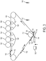
- the platen 118 moves (using motors, gears, pulleys, cables, guides, etc. (all generally illustrated by item 118)) toward the ITB 110 to have the platen 118 make contact with the ITB 110.
- the ITB 110 transfers one of the developed layers 102 of the build materials 104 and the support material 105 to the platen 118 each time the platen 118 contacts the ITB 110, to successively form developed layers 102 of the build material 104 and the support material 105 on the platen 118.
- the leading edge 134 of the developed layer 102 within the transfer nip 130 begins to be transferred to a corresponding location of the platen 118.
- the platen 118 moves to contact the developed layer 102 on the ITB 110 at a location where the leading edge 134 of the developed layer 102 is at the lowest location of the roller of the transfer nip 130.
- the trailing edge 136 of the developed layer 102 has not yet reached the transfer nip 130 and has not, therefore, yet been transferred to the platen 118.
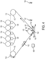
- the platen 118 moves synchronously with the ITB 110 (moves at the same speed and the same direction as the ITB 110) either by moving or rotating the platen vacuum belt, to allow the developed layers 102 to transfer cleanly to the platen 118, without smearing.
- the trailing edge 136 of the developed layer 102 is the only portion that has not yet reached the transfer nip 130 and has not, therefore, been transferred to the platen 118.
- the platen 118 moves at the same speed and in the same direction as the ITB 110, until the trailing edge 136 of the developed layer 102 reaches the bottom of the roller of the transfer nip 130, at which point the platen 118 moves away from the ITB 110 and over to the fusing station 142, as shown in Figure 5 .
- the platen 118 can move to the fusing station 142 after each time the ITB 110 transfers each of the developed layers 102 to the platen 118 to independently fuse (using laser light 146) each of the developed layers 102 and successively join each developed layer 102 to the platen 118 and to any previously transferred developed layers 102 on the platen 118.
- the platen 118 may only move to the fusing station 142 after a specific number (e.g., 2, 3, 4, etc.) of the developed layers 102 have been placed on the platen 118 to allow multiple developed layers 102 to be simultaneously fused to the platen 118 and to each other.
- Figures 6A-6C illustrates one of the layers 102 being processed at the fusing station 142. More specifically, in Figure 6A , laser light 146 fuses (melts, sinters, bonds, joins, binds, etc.) a portion of build materials 103 and 104, but may not fuse the support material 105.
- the system controlling the laser fusing device 142 can registered the develop layer 102 to the laser 142. With knowledge of the upcoming image, the laser 142 is adjusted to optimize the power applied to each different material 103, 104 within the layer 102.
- the fusing station 142 can supply different energy levels of laser light 146 (e.g., through different exposure times, different power levels, different wavelengths, etc.) to different portions of build material 103, 104 to fuse the different build materials 103, 104 differently (without applying any laser light 146 to the support material 105, thus preventing the support material 105 from fusing).
- the laser light 146 heats the different materials 103, 104 differently to fuse the portions of build material 103, 104 together, without heating the support material 10,5 to leave the support material 105 as a loose, unbound (e.g., powder or granular) material.
- the portions of build material 103, 104 to which laser light 146 is applied are less than all of the different materials within the layer 102 (thus, these portions of build material 103, 104 and the support material 105 are different portions of the same layer 102).
- different build materials 103 and 104 may be developed by different development devices (e.g. 152, 154) and therefore may comprise different materials, with different physical and fusing characteristics. Therefore, the laser fuse station 142 can supply different levels of energy to different portions of the layer 102 in order to cause the potentially different materials 103, 104 to be bonded together. In other situations, the fusing station 142 can apply different energies to different portions of the same build material (again represented in Figure 6A by items 103 and 104) to cause different reactions within the material, so as to differentiate the fused materials and cause such materials to have different densities, different elasticities, different colors, different textures, etc., and thus distinguish items 103 and 104 in the final 3-D printed product that is output.
- fused materials may shrink. Therefore, if the build material 103, 104 is fused, and the support material 105 is not fused, this may create a height difference between the build and support materials, post-fusing.
- the development devices 150-158 compensate for this post-fusing height difference (e.g., between the fused build material and non-fused support material) by developing the layers 102 on the ITB 110 to have different pre-fusing thicknesses. Therefore, a specific development device (152-158) may deposit more material (a higher stack of material) on the ITB 110, relative to the other materials within a given layer 102, if it is known that such a material will shrink when fused by the laser fusing device 142.
- Figures 6B and 6C illustrate that all the materials within the layer 102 can be blanket exposed by the laser fusing device 142 (in the X and/or Y directions, where the entire layer 102 is exposed to the laser light 146).
- the support material 105 can be selected so that only the support material 105 is not affected by the laser light 146 (but all other portions of the layer 102 are fused by the laser light 146).
- the support material 105 can be a non-sinterable material including ceramics, glass beads, sand, etc., that does not fuse or melt in the presence of the power of laser light energy being applied by the laser fusing device 142.
- materials 102 can be fused (without being fully melted) by the laser light 146 heating such materials 102 to a temperature between their glass transition temperature and their melting temperature, to join the materials 102 as one, without affecting their shape or pattern, thereby creating a rigid structure.
- the selection of build and support materials is coordinated with the power and exposure of the fusing process.
- other fusing processing and components could be used, and the foregoing is presented only as one limited example; and the devices and methods herein are applicable to all such methods and components, whether currently known or developed in the future.
- the processing in Figures 2-5 is repeated to fuse multiple developed layers 102 into a stack 106, as shown in Figure 7 .
- the laser fusing station 142 not only fuses together the material within each of the developed layers 102, the laser fusing station 142 also fuses each developed player 102 to the immediately adjacent developed layer 102 that was most recently transferred to the platen 118 (e.g., joins layers 102 that contact one another on the platen 118).
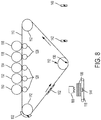
- Figure 8 illustrates that the adhesive application station 166 can be positioned to supply adhesive to the platen 118 (or to the top layers 102 thereon) before the platen returns to the transfer nip 130.
- adhesive promotes transfer of the layers 102 from the intermediate transfer surface 110 to the layers 102 on the platen 118 at the transfer station 130.
- the adhesive applied at station 166 can be any commercially available adhesive product that is selected to not affect the support or build materials, and can be applied by spraying, rolling, brushing, etc.
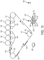
- the laser fusing station 142 can perform fusing after each time the ITB 110 transfers each of the developed layers 102 to the platen 118, or fusing can be performed less frequently such as only once (e.g., when the entire stack 106 is completely formed).
- Figure 11 illustrates an overlay showing portions of support material 105 and build material 103, 104 within the accumulation of the freestanding stack 106 after all layers have been transferred to the platen 118 and fused.
- Such overlay may or may not be visible, and is only illustrated to show one exemplary way in which such build and support materials may be arranged.
- the 3-D structure of the freestanding stack 106 shown in Figure 11 can be output to allow manual removal of the support material 105 using air pressure, an external solvent bath, etc; or automated processing can proceed as shown in Figure 12-16 .
- the platen 118 (with the freestanding stack 106 thereon) can move to be positioned above a collection tray 160.
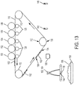
- the acoustic vibrator 144 can be actuated to vibrate the unfused support material 105 off the fused build material 103, 104 to leave the freestanding part 103, 104 of built material remaining on the platen 118. This allows the support material 105 to be collected in the collection tray 160 and potentially reused within the support material development device 150.
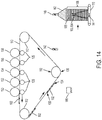
- the support material removal station 148 is positioned to receive the now fused 3-D freestanding stack 106 on the platen 118, as the platen 118 moves.
- the support material removal station 148 applies a solvent, water, air, etc., 162. Any solvent 162 applied by the support material removal station 148 is selected to dissolve the support material 105 without affecting the build material 103, 104.
- 105 pressurized air 162 can be used to blow the unfused support material 105 off the fused build material 103, 104 (if the support material remains in powder or granular form).
- the solvent utilized will depend upon the chemical makeup of the build material 103, 104 and the support material 105.
- Figure 15 illustrates the processing where about half of the support material 105 remains, and a portion of the build material 103, 104 protrudes from the remaining stack of support material 105.
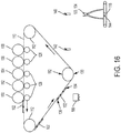
- Figure 16 illustrates processing after the support material removal station 148 has dissolved or removed all the support material 105, leaving only the build material 103, 104 remaining, which leave a completed 3-D structure made of only the build material 104.
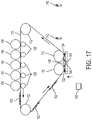
- FIGs 17 and 18 illustrate an alternative 3-D electrostatic printing structure herein that includes a planar transfer station 138 in place of the transfer nip 130 shown in Figure 1 .
- the planar transfer station 138 is a planar portion of the ITB 110 that is between rollers 112 and is parallel to the platen 118.
- the layers 102 are selectively laser fused using fusing station 142, as shown in Figure 18 .
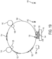
- a drum 164 could be used in place of the ITB 110, with all other components operating as described herein.
- the drum 164 could be an intermediate transfer surface receiving material from development stations 152-158, as described above, or could be a photoreceptor and operate as the photoreceptor 256 described below operates, by maintaining a latent image of charge and receiving materials from development devices 254.
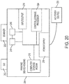
- FIG. 20 illustrates many components of 3-D printer structures 204 herein.
- the 3-D printing device 204 includes a controller/tangible processor 224 and a communications port (input/output) 214 operatively connected to the tangible processor 224 and to a computerized network external to the printing device 204.
- the printing device 204 can include at least one accessory functional component, such as a graphical user interface (GUI) assembly 212.
- GUI graphical user interface
- the user may receive messages, instructions, and menu options from, and enter instructions through, the graphical user interface or control panel 212.
- the input/output device 214 is used for communications to and from the 3-D printing device 204 and comprises a wired device or wireless device (of any form, whether currently known or developed in the future).
- the tangible processor 224 controls the various actions of the printing device 204.
- a non-transitory, tangible, computer storage medium device 210 (which can be optical, magnetic, capacitor based, etc., and is different from a transitory signal) is readable by the tangible processor 224 and stores instructions that the tangible processor 224 executes to allow the computerized device to perform its various functions, such as those described herein.
- a body housing has one or more functional components that operate on power supplied from an alternating current (AC) source 220 by the power supply 218.
- the power supply 218 can comprise a common power conversion unit, power storage element (e.g., a battery, etc), etc.
- the 3-D printing device 204 includes at least one marking device (printing engine(s)) 240 that deposits successive layers of build and support material on a platen as described above, and are operatively connected to a specialized image processor 224 (that is different than a general purpose computer because it is specialized for processing image data). Also, the printing device 204 can include at least one accessory functional component (such as a scanner 232) that also operates on the power supplied from the external power source 220 (through the power supply 218).
- a marking device printing engine(s)
- a specialized image processor 224 that is different than a general purpose computer because it is specialized for processing image data.
- the printing device 204 can include at least one accessory functional component (such as a scanner 232) that also operates on the power supplied from the external power source 220 (through the power supply 218).
- the one or more printing engines 240 are intended to illustrate any marking device that applies build and support materials (toner, etc.) whether currently known or developed in the future and can include, for example, devices that use an intermediate transfer belt 110 (as shown in Figure 21 ).
- each of the printing engine(s) 240 shown in Figure 20 can utilize one or more potentially different (e.g., different color, different material, etc.) build material development stations 152-158, one or more potentially different (e.g., different color, different material, etc.) support material development stations 150, etc.
- the development stations 152-158 can be any form of development station, whether currently known or developed in the future, such as individual electrostatic marking stations, individual inkjet stations, individual dry ink stations, etc.
- Each of the development stations 150-158 transfers a pattern of material to the same location of the intermediate transfer belt 110 in sequence during a single belt rotation (potentially independently of a condition of the intermediate transfer belt 110) thereby, reducing the number of passes the intermediate transfer belt 110 must make before a full and complete image is transferred to the intermediate transfer belt 110.
- Figure 21 illustrates five development stations adjacent or in contact with a rotating belt (110), as would be understood by those ordinarily skilled in the art, such devices could use any number of marking stations (e.g., 2, 3, 5, 8, 11, etc.).
- Each of the individual electrostatic development stations 152-158 includes its own charging station 258 that creates a uniform charge on an internal photoreceptor 256, an internal exposure device 260 that patterns the uniform charge into a latent image of charge, and an internal development device 254 that transfers build or support material to the photoreceptor 256 in a pattern matching the charge latent image.
- the pattern of build or support material is then drawn from the photoreceptor 256 to the intermediate transfer belt 110 by way of an opposite charge of the intermediate transfer belt 110 relative to the charge of the build or support material, that is usually created by a charge generator 128 on the opposite side of the intermediate transfer belt 110.
- an additive manufacturing system for printing a 3-D part using electrophotography includes a photoconductor component having a surface, and a development station, where the development station is configured to developed layers of a material on the surface of the photoconductor component.
- the system also includes a transfer medium configured to receive the developed layers from the surface of the rotatable photoconductor component, and a platen configured to receive the developed layers from the transfer component in a layer-by-layer manner to print the 3-D part from at least a portion of the received layers.
- Computerized devices that include chip-based central processing units (CPU's), input/output devices (including graphic user interfaces (GUI), memories, comparators, tangible processors, etc.) are well-known and readily available devices produced by manufacturers such as Dell Computers, Round Rock TX, USA and Apple Computer Co., Cupertino CA, USA.
- Such computerized devices commonly include input/output devices, power supplies, tangible processors, electronic storage memories, wiring, etc., the details of which are omitted herefrom to allow the reader to focus on the salient aspects of the systems and methods described herein.
- printers, copiers, scanners and other similar peripheral equipment are available from Xerox Corporation, Norwalk, CT, USA and the details of such devices are not discussed herein for purposes of brevity and reader focus.
- printer or printing device encompasses any apparatus, such as a digital copier, bookmaking machine, facsimile machine, multifunction machine, etc., which performs a print outputting function for any purpose.
- the details of printers, printing engines, etc. are well-known and are not described in detail herein to keep this disclosure focused on the salient features presented.
- the systems and methods herein can encompass systems and methods that print in color, monochrome, or handle color or monochrome image data. All foregoing systems and methods are specifically applicable to electrostatographic and/or xerographic machines and/or processes.
- the term fixing means the drying, hardening, polymerization, crosslinking, binding, or addition reaction or other reaction of the coating.
- terms such as “right”, “left”, “vertical”, “horizontal”, “top”, “bottom”, “upper”, “lower”, “under”, “below”, “underlying”, “over”, “overlying”, “parallel”, “perpendicular”, etc., used herein are understood to be relative locations as they are oriented and illustrated in the drawings (unless otherwise indicated). Terms such as “touching”, “on”, “in direct contact”, “abutting”, “directly adjacent to”, etc., mean that at least one element physically contacts another element (without other elements separating the described elements).
- the terms automated or automatically mean that once a process is started (by a machine or a user), one or more machines perform the process without further input from any user.
- the same identification numeral identifies the same or similar item.
Landscapes
- Engineering & Computer Science (AREA)
- Chemical & Material Sciences (AREA)
- Materials Engineering (AREA)
- Manufacturing & Machinery (AREA)
- Physics & Mathematics (AREA)
- Optics & Photonics (AREA)
- Mechanical Engineering (AREA)
- General Physics & Mathematics (AREA)
- Plasma & Fusion (AREA)
- Health & Medical Sciences (AREA)
- Toxicology (AREA)
- Ceramic Engineering (AREA)
- Combination Of More Than One Step In Electrophotography (AREA)
- Fixing For Electrophotography (AREA)
- Electrostatic Charge, Transfer And Separation In Electrography (AREA)
Abstract
Description
- Systems and methods herein generally relate to three-dimensional (3-D) printing processes that use electrostatic printing processes.
- Three-dimensional printing can produce objects using, for example, ink-jet printers. In many systems, a platform moves below an ink-jet to form a layer of build and support materials, and each layer is hardened using a UV light source. These steps are repeated layer-by-layer. Support materials generally comprise acid-, base- or water-soluble polymers, which can be selectively rinsed from the build material after 3-D printing is complete.
- The electrostatic (electro-photographic) process is a well-known means of generating two-dimensional digital images, which transfer materials onto an intermediate surface (such as a photoreceptor belt or drum). Advancements in the way an electro-photographic image is transferred can leverage the speed, efficiency and digital nature of printing systems.
- Exemplary three-dimensional (3-D) printers include, among other components, an intermediate transfer surface, development stations positioned to electrostatically transfer different materials to the intermediate transfer surface, and a transfer station adjacent the intermediate transfer surface. The transfer station is positioned to receive layers of the different materials as the intermediate transfer surface moves past the transfer station. Thus, the development stations and the transfer station are positioned relative to the intermediate transfer surface such that a point on the intermediate transfer surface, when the intermediate transfer surface moves in a process direction, first passes the development stations and then passes the transfer station.
- Such structures also include a platen moving relative to the intermediate transfer surface. The intermediate transfer surface transfers a layer of the different materials to the platen each time the platen contacts one of the layers on the intermediate transfer surface at the transfer station to successively form a freestanding stack of the layers on the platen. In addition, an adhesive station can be positioned to supply adhesive to the platen (or the layers thereon). Such adhesive promotes transfer of the layers from the intermediate transfer surface to the layers on the platen at said transfer station.
- Also, a laser fusing station is positioned to apply laser light to each the layer immediately after the layer is transferred from the transfer station to the platen. The laser fusing station selectively applies the laser light differently to the different materials within the layer to fuse together portions (e.g., portions of build material) of the different materials within the layer. However, the laser fusing station does not apply the laser light to a second portion of the different materials (e.g., support material) within the layer. Thus, the laser light heats the different materials to fuse the portions of build material together, without heating the support material to leave the support material as a loose, unbound material. The portions of build material to which laser light is applied are less than all of the layer (thus, and these portions of build material and the support material are different portions within the layer).
- The 3-D printer can also optionally include a material removal station positioned to remove the support material of the different materials within the layer to separate the portions of build material of the different materials from the support material of the different materials and leave a 3-D printed part. For example, the material removal station can include an acoustic vibrator, a solvent rinsing device, a pressurized air blower, etc.
- These and other features are described in, or are apparent from, the following detailed description.
- Various exemplary systems and methods are described in detail below, with reference to the attached drawing figures, in which:
-
Figures 1-5 are schematic cross-section diagrams partially illustrating printing devices herein; -
Figures 6A-6C are expanded schematic diagrams illustrating laser fusing devices herein; -
Figure 7 is an expanded schematic diagram illustrating stacks of layers formed by devices herein; -
Figures 8-19 are schematic cross-section diagrams partially illustrating printing devices herein; -
Figure 20 is a schematic diagram illustrating a 3-D printing device herein; -
Figure 21 is a schematic diagram illustrating a printing engine herein; and -
Figure 22 is an expanded schematic diagram illustrating a development device herein. - As mentioned above, electrostatic printing process are well-known means of generating two-dimensional (2-D) digital images, and the methods and devices herein use such processing for the production of 3-D items (for 3-D printing). However, when performing 3-D printing using electrostatic processes (especially those that use an ITB), the thermal management is a challenge because of the high temperatures used to transfer the material from the ITB to a platen, where the ITB is cooled before returning to the development device(s). Additionally, with 3-D printing that uses electrostatic processes, the mechanical integrity of the printed material may be compromised if it is very thin, and the transfer process can impose stripping shear forces that damage the material.
- In order to address such issues, this disclosure provides a hybrid architecture that combines electrostatic printing with laser sintering. This involves using an electrostatic system to create layers of materials such as thermoplastics, ceramics, etc., and uses a laser to digitally fuse the layers in order to create a 3-D part. The devices and methods herein take advantage of the fast image and material management process of electrostatic printing, in order to digitally manage different printed materials, and then utilizes a laser to sinter the functional /engineering materials. Further, these methods and devices do not use heat at the transfer nip and do not perform post-transfer heated roller fusing, which avoids high temperatures used to transfer and fuse the material. Thus, the processing herein is relatively cool, and limits any pausing needed to allow structures to cool down (and does not require additional cooling stations) which makes the 3-D printing process faster and the devices less expensive.
- The devices and methods herein can use a series of photoreceptor stations, one for each different material. Each of the stations develops and transfers an image into an intermediate transfer belt (ITB) electrostatically. The multiple material images are combined into a single developed layer on the ITB. The developed layer is then transferred to a surface build plate (platen) electrostatically, or using adhesive on the platen to help the developed layer remain attached. Once the developed layer has been transferred into the platen, the platen moves to the laser sintering station. The sintering station fuses the material particles in order to create a solid part. Once the sintering is performed, the platen moves to the home (initial) position to repeat the process and add the next layer. This process repeats until a solid part is created.
- In different examples presented herein, the support material may comprise a type of material that the laser will not fuse or melt (e.g., ceramic, glass beads, etc.). By not sintering, the support material stays in powder state. The powdered material can be removed mechanically by vibrations or air pressure (and the support material can be recovered and reused). Alternatively, the support material can be dissolved chemically (or by water), without affecting the build material. Also, material selection is managed, as are fusing characteristics, to achieve a match of post-fusing material shrinkage characteristics.
- Thus, the devices and methods herein are able to create parts or assemblies with multiple materials and colors, digitally manage and combine multiple materials in order to create new material properties, and provide the ability to optimize laser power per material. This eliminates heat management issues by not heating the ITB, and this makes the printing faster. This also takes advantage of fast electrostatic printing processes to create 3-D items faster.
- As shown, for example, in
Figure 1 , exemplary three-dimensional (3-D) printers herein include, among other components, an intermediate transfer belt 110 (ITB) supported onrollers 112, one or more printing/development units such as a first printing component (e.g., development device 116), and a second printing component (e.g., development device 114). Thus, as shown inFigure 1 , thefirst printing component 116 is positioned to electrostatically transfer afirst material 104, the build material, such as a (potentially dry) powder polymer-wax material (e.g., charged 3-D toner) to theITB 110. The electrostatic transfer occurs by way of charge difference between the belt (produced bycharge generator 128, for example) and the material being transferred 104. The second printing component 114 (which can also be, for example, a photoreceptor) is also positioned to electrostatically transfer a second material 105 (e.g., the support material) to a location of the ITB 110 where thefirst material 104 is located on the ITB 110. - In the drawings, the combination of the
build material 104 and thesupport material 105 is shown aselement 102, and is sometimes referred to as a "developed layer." Thedeveloped layer 102 of thebuild material 104 and thesupport material 105 is on a discrete area of theITB 110 and is in a pattern corresponding to the components of the 3-D structure in that layer (and its associated support elements), where the 3-D structure is being built, developedlayer 102 bydeveloped layer 102. - In
Figure 1 ,item 118 is a platen (which can include an acoustic vibrator element 144),item 142 is a fusing station (e.g., laser),item 166 is an adhesive application station, anditem 148 is a support material removal station. Additionally,item 130 is a transfer nip, anditems developed layer 102. - Devices herein can include only one development device, or can include many. Therefore, the remaining drawings illustrate different color development stations 152-158 (shown in
Figure 2 ) positioned to electrostatically transfer different color build materials (e.g.,items 103 and 104) to an intermediate transfer belt (ITB 110); and at least one supportmaterial development station 150 positioned to electrostatically transfer support material to a location of theITB 110 where the build materials are located on theITB 110. For example, each different development station 152-158 can provide a color of build material that is different from the colors of the build materials supplied by other development stations 152-158. The color of the support material provided bydevelopment station 150 is not highly relevant because the support material is eventually removed from the final structure, as discussed below. - Additionally, the platen 118 (which can be a surface or belt) is adjacent the
ITB 110. In this example, theplaten 118 is a vacuum belt.Patterned layers 102 of build and support material are transferred from the development devices 152-158 to theintermediate transfer belt 110, and eventually to theplaten 118 at thetransfer station 130. - As shown in
Figure 2 , thetransfer station 130 is adjacent theITB 110. Thetransfer station 130 includes aroller 112, on one side of theITB 110, supporting theITB 110. Thetransfer station 130 is positioned to receive thelayers 102 as theITB 110 moves to thetransfer station 130. More specifically, the build material development stations 152-158, the supportmaterial development station 150, and thetransfer station 130 are positioned relative to theITB 110 such that alayer 102 on theITB 110, when theITB 110 is moving in a process direction, first passes the build material and support material development stations 150-158, and then passes thetransfer station 130. - Therefore, the build and support material that is printed in a pattern on the ITB by each separate development device 150-158, is combined together in the
developed layers 102 to represent a specific pattern having a predetermined length. Thus, as shown inFigure 2 , each of thedeveloped layers 102 has aleading edge 134 oriented toward the processing direction in which theITB 110 is moving (represented by arrows next to the ITB 110) and a trailingedge 136 opposite theleading edge 134. - As shown by the vertical arrow in
Figure 3 , theplaten 118 moves (using motors, gears, pulleys, cables, guides, etc. (all generally illustrated by item 118)) toward theITB 110 to have theplaten 118 make contact with theITB 110. Thereby, theITB 110 transfers one of thedeveloped layers 102 of thebuild materials 104 and thesupport material 105 to theplaten 118 each time theplaten 118 contacts theITB 110, to successively formdeveloped layers 102 of thebuild material 104 and thesupport material 105 on theplaten 118. - More specifically, as shown in
Figure 3 , at the transfer nip 130, theleading edge 134 of the developedlayer 102 within the transfer nip 130 begins to be transferred to a corresponding location of theplaten 118. Thus, inFigure 3 , theplaten 118 moves to contact thedeveloped layer 102 on theITB 110 at a location where theleading edge 134 of the developedlayer 102 is at the lowest location of the roller of the transfer nip 130. Thus, in this example, the trailingedge 136 of the developedlayer 102 has not yet reached the transfer nip 130 and has not, therefore, yet been transferred to theplaten 118. - As shown in
Figure 4 , theplaten 118 moves synchronously with the ITB 110 (moves at the same speed and the same direction as the ITB 110) either by moving or rotating the platen vacuum belt, to allow thedeveloped layers 102 to transfer cleanly to theplaten 118, without smearing. InFigure 4 , the trailingedge 136 of the developedlayer 102 is the only portion that has not yet reached the transfer nip 130 and has not, therefore, been transferred to theplaten 118. Then, as theITB 110 moves in the processing direction, theplaten 118 moves at the same speed and in the same direction as theITB 110, until the trailingedge 136 of the developedlayer 102 reaches the bottom of the roller of the transfer nip 130, at which point theplaten 118 moves away from theITB 110 and over to the fusingstation 142, as shown inFigure 5 . - The
platen 118 can move to the fusingstation 142 after each time theITB 110 transfers each of thedeveloped layers 102 to theplaten 118 to independently fuse (using laser light 146) each of thedeveloped layers 102 and successively join eachdeveloped layer 102 to theplaten 118 and to any previously transferred developedlayers 102 on theplaten 118. In other alternatives, theplaten 118 may only move to the fusingstation 142 after a specific number (e.g., 2, 3, 4, etc.) of thedeveloped layers 102 have been placed on theplaten 118 to allow multipledeveloped layers 102 to be simultaneously fused to theplaten 118 and to each other. -
Figures 6A-6C illustrates one of thelayers 102 being processed at the fusingstation 142. More specifically, inFigure 6A ,laser light 146 fuses (melts, sinters, bonds, joins, binds, etc.) a portion ofbuild materials support material 105. In one example, the system controlling thelaser fusing device 142 can registered thedevelop layer 102 to thelaser 142. With knowledge of the upcoming image, thelaser 142 is adjusted to optimize the power applied to eachdifferent material layer 102. - As shown by the different shading in
Figure 6A , the fusingstation 142 can supply different energy levels of laser light 146 (e.g., through different exposure times, different power levels, different wavelengths, etc.) to different portions ofbuild material different build materials laser light 146 to thesupport material 105, thus preventing thesupport material 105 from fusing). Thus, thelaser light 146 heats thedifferent materials build material support material 105 as a loose, unbound (e.g., powder or granular) material. The portions ofbuild material laser light 146 is applied are less than all of the different materials within the layer 102 (thus, these portions ofbuild material support material 105 are different portions of the same layer 102). - For example,
different build materials laser fuse station 142 can supply different levels of energy to different portions of thelayer 102 in order to cause the potentiallydifferent materials station 142 can apply different energies to different portions of the same build material (again represented inFigure 6A byitems 103 and 104) to cause different reactions within the material, so as to differentiate the fused materials and cause such materials to have different densities, different elasticities, different colors, different textures, etc., and thus distinguishitems - Note that fused materials may shrink. Therefore, if the
build material support material 105 is not fused, this may create a height difference between the build and support materials, post-fusing. The development devices 150-158 compensate for this post-fusing height difference (e.g., between the fused build material and non-fused support material) by developing thelayers 102 on theITB 110 to have different pre-fusing thicknesses. Therefore, a specific development device (152-158) may deposit more material (a higher stack of material) on theITB 110, relative to the other materials within a givenlayer 102, if it is known that such a material will shrink when fused by thelaser fusing device 142. This ensures that, after fusing, the fusedportions non-fused portions 105. This allows each new layer of fused build material that is formed within the 3-D item being printed to be planer, which keeps the 3-D item free of undesirable distortion. -
Figures 6B and 6C illustrate that all the materials within thelayer 102 can be blanket exposed by the laser fusing device 142 (in the X and/or Y directions, where theentire layer 102 is exposed to the laser light 146). In such situations, thesupport material 105 can be selected so that only thesupport material 105 is not affected by the laser light 146 (but all other portions of thelayer 102 are fused by the laser light 146). For example, thesupport material 105 can be a non-sinterable material including ceramics, glass beads, sand, etc., that does not fuse or melt in the presence of the power of laser light energy being applied by thelaser fusing device 142. - Regarding the fusing process,
materials 102 can be fused (without being fully melted) by thelaser light 146 heatingsuch materials 102 to a temperature between their glass transition temperature and their melting temperature, to join thematerials 102 as one, without affecting their shape or pattern, thereby creating a rigid structure. Those ordinarily skilled in the art would understand that the selection of build and support materials is coordinated with the power and exposure of the fusing process. Further, other fusing processing and components could be used, and the foregoing is presented only as one limited example; and the devices and methods herein are applicable to all such methods and components, whether currently known or developed in the future. - Thus, the processing in
Figures 2-5 is repeated to fuse multipledeveloped layers 102 into astack 106, as shown inFigure 7 . Thelaser fusing station 142 not only fuses together the material within each of thedeveloped layers 102, thelaser fusing station 142 also fuses eachdeveloped player 102 to the immediately adjacentdeveloped layer 102 that was most recently transferred to the platen 118 (e.g., joinslayers 102 that contact one another on the platen 118). -
Figure 8 illustrates that theadhesive application station 166 can be positioned to supply adhesive to the platen 118 (or to thetop layers 102 thereon) before the platen returns to the transfer nip 130. Such adhesive promotes transfer of thelayers 102 from theintermediate transfer surface 110 to thelayers 102 on theplaten 118 at thetransfer station 130. The adhesive applied atstation 166 can be any commercially available adhesive product that is selected to not affect the support or build materials, and can be applied by spraying, rolling, brushing, etc. - As the
stack 106 of thedeveloped layers 102 grows, additionaldeveloped layers 102 are formed on top of thestack 106, as shown inFigure 9 , and such additionaldeveloped layers 102 are fused together by thelaser fusing station 142 inFigure 10 , to fuse all the develop layers 102 within thestack 106 together. In one example, thelaser fusing station 142 can perform fusing after each time theITB 110 transfers each of thedeveloped layers 102 to theplaten 118, or fusing can be performed less frequently such as only once (e.g., when theentire stack 106 is completely formed). In addition,Figure 11 illustrates an overlay showing portions ofsupport material 105 and buildmaterial freestanding stack 106 after all layers have been transferred to theplaten 118 and fused. Such overlay may or may not be visible, and is only illustrated to show one exemplary way in which such build and support materials may be arranged. - The 3-D structure of the
freestanding stack 106 shown inFigure 11 can be output to allow manual removal of thesupport material 105 using air pressure, an external solvent bath, etc; or automated processing can proceed as shown inFigure 12-16 . More specifically, as shown inFigure 12 , the platen 118 (with thefreestanding stack 106 thereon) can move to be positioned above acollection tray 160. As shown inFigure 13 , theacoustic vibrator 144 can be actuated to vibrate theunfused support material 105 off the fusedbuild material freestanding part platen 118. This allows thesupport material 105 to be collected in thecollection tray 160 and potentially reused within the supportmaterial development device 150. - In another arrangement, in
Figure 14 , the supportmaterial removal station 148 is positioned to receive the now fused 3-Dfreestanding stack 106 on theplaten 118, as theplaten 118 moves. The supportmaterial removal station 148 applies a solvent, water, air, etc., 162. Any solvent 162 applied by the supportmaterial removal station 148 is selected to dissolve thesupport material 105 without affecting thebuild material pressurized air 162 can be used to blow theunfused support material 105 off the fusedbuild material 103, 104 (if the support material remains in powder or granular form). Again, as noted above, the solvent utilized will depend upon the chemical makeup of thebuild material support material 105.Figure 15 illustrates the processing where about half of thesupport material 105 remains, and a portion of thebuild material support material 105.Figure 16 illustrates processing after the supportmaterial removal station 148 has dissolved or removed all thesupport material 105, leaving only thebuild material build material 104. -
Figures 17 and18 illustrate an alternative 3-D electrostatic printing structure herein that includes aplanar transfer station 138 in place of the transfer nip 130 shown inFigure 1 . As shown inFigure 17 , theplanar transfer station 138 is a planar portion of theITB 110 that is betweenrollers 112 and is parallel to theplaten 118. As shown inFigure 17 , with this structure, when theplaten 118 moves to contact theplanar transfer station 138, all of the developedlayer 102 is transferred simultaneously to theplaten 118 or partially formedstack 106, avoiding the rolling transfers process shown inFigures 3 and4 . As discussed above, thelayers 102 are selectively laser fused using fusingstation 142, as shown inFigure 18 . - Similarly, as shown in
Figure 19 , adrum 164 could be used in place of theITB 110, with all other components operating as described herein. Thus, thedrum 164 could be an intermediate transfer surface receiving material from development stations 152-158, as described above, or could be a photoreceptor and operate as thephotoreceptor 256 described below operates, by maintaining a latent image of charge and receiving materials fromdevelopment devices 254. -
Figure 20 illustrates many components of 3-D printer structures 204 herein. The 3-D printing device 204 includes a controller/tangible processor 224 and a communications port (input/output) 214 operatively connected to thetangible processor 224 and to a computerized network external to theprinting device 204. Also, theprinting device 204 can include at least one accessory functional component, such as a graphical user interface (GUI)assembly 212. The user may receive messages, instructions, and menu options from, and enter instructions through, the graphical user interface orcontrol panel 212. - The input/
output device 214 is used for communications to and from the 3-D printing device 204 and comprises a wired device or wireless device (of any form, whether currently known or developed in the future). Thetangible processor 224 controls the various actions of theprinting device 204. A non-transitory, tangible, computer storage medium device 210 (which can be optical, magnetic, capacitor based, etc., and is different from a transitory signal) is readable by thetangible processor 224 and stores instructions that thetangible processor 224 executes to allow the computerized device to perform its various functions, such as those described herein. Thus, as shown inFigure 20 , a body housing has one or more functional components that operate on power supplied from an alternating current (AC)source 220 by thepower supply 218. Thepower supply 218 can comprise a common power conversion unit, power storage element (e.g., a battery, etc), etc. - The 3-
D printing device 204 includes at least one marking device (printing engine(s)) 240 that deposits successive layers of build and support material on a platen as described above, and are operatively connected to a specialized image processor 224 (that is different than a general purpose computer because it is specialized for processing image data). Also, theprinting device 204 can include at least one accessory functional component (such as a scanner 232) that also operates on the power supplied from the external power source 220 (through the power supply 218). - The one or
more printing engines 240 are intended to illustrate any marking device that applies build and support materials (toner, etc.) whether currently known or developed in the future and can include, for example, devices that use an intermediate transfer belt 110 (as shown inFigure 21 ). - Thus, as shown in
Figure 21 , each of the printing engine(s) 240 shown inFigure 20 can utilize one or more potentially different (e.g., different color, different material, etc.) build material development stations 152-158, one or more potentially different (e.g., different color, different material, etc.) supportmaterial development stations 150, etc. The development stations 152-158 can be any form of development station, whether currently known or developed in the future, such as individual electrostatic marking stations, individual inkjet stations, individual dry ink stations, etc. Each of the development stations 150-158 transfers a pattern of material to the same location of theintermediate transfer belt 110 in sequence during a single belt rotation (potentially independently of a condition of the intermediate transfer belt 110) thereby, reducing the number of passes theintermediate transfer belt 110 must make before a full and complete image is transferred to theintermediate transfer belt 110. WhileFigure 21 illustrates five development stations adjacent or in contact with a rotating belt (110), as would be understood by those ordinarily skilled in the art, such devices could use any number of marking stations (e.g., 2, 3, 5, 8, 11, etc.). - One exemplary individual electrostatic development station 152-158 is shown in
Figure 22 positioned adjacent to (or potentially in contact with)intermediate transfer belt 110. Each of the individual electrostatic development stations 152-158 includes itsown charging station 258 that creates a uniform charge on aninternal photoreceptor 256, aninternal exposure device 260 that patterns the uniform charge into a latent image of charge, and aninternal development device 254 that transfers build or support material to thephotoreceptor 256 in a pattern matching the charge latent image. The pattern of build or support material is then drawn from thephotoreceptor 256 to theintermediate transfer belt 110 by way of an opposite charge of theintermediate transfer belt 110 relative to the charge of the build or support material, that is usually created by acharge generator 128 on the opposite side of theintermediate transfer belt 110. - While some exemplary structures are illustrated in the attached drawings, those ordinarily skilled in the art would understand that the drawings are simplified schematic illustrations and that the claims presented below encompass many more features that are not illustrated (or potentially many less) but that are commonly utilized with such devices and systems. Therefore, Applicants do not intend for the claims presented below to be limited by the attached drawings, but instead the attached drawings are merely provided to illustrate a few ways in which the claimed features can be implemented.
- As shown in
US 8,488,994 , an additive manufacturing system for printing a 3-D part using electrophotography is known. The system includes a photoconductor component having a surface, and a development station, where the development station is configured to developed layers of a material on the surface of the photoconductor component. The system also includes a transfer medium configured to receive the developed layers from the surface of the rotatable photoconductor component, and a platen configured to receive the developed layers from the transfer component in a layer-by-layer manner to print the 3-D part from at least a portion of the received layers. - While some exemplary structures are illustrated in the attached drawings, those ordinarily skilled in the art would understand that the drawings are simplified schematic illustrations and that the claims presented below encompass many more features that are not illustrated (or potentially many less) but that are commonly utilized with such devices and systems. Therefore, Applicants do not intend for the claims presented below to be limited by the attached drawings, but instead the attached drawings are merely provided to illustrate a few ways in which the claimed features can be implemented.
- Many computerized devices are discussed above. Computerized devices that include chip-based central processing units (CPU's), input/output devices (including graphic user interfaces (GUI), memories, comparators, tangible processors, etc.) are well-known and readily available devices produced by manufacturers such as Dell Computers, Round Rock TX, USA and Apple Computer Co., Cupertino CA, USA. Such computerized devices commonly include input/output devices, power supplies, tangible processors, electronic storage memories, wiring, etc., the details of which are omitted herefrom to allow the reader to focus on the salient aspects of the systems and methods described herein. Similarly, printers, copiers, scanners and other similar peripheral equipment are available from Xerox Corporation, Norwalk, CT, USA and the details of such devices are not discussed herein for purposes of brevity and reader focus.
- The terms printer or printing device as used herein encompasses any apparatus, such as a digital copier, bookmaking machine, facsimile machine, multifunction machine, etc., which performs a print outputting function for any purpose. The details of printers, printing engines, etc., are well-known and are not described in detail herein to keep this disclosure focused on the salient features presented. The systems and methods herein can encompass systems and methods that print in color, monochrome, or handle color or monochrome image data. All foregoing systems and methods are specifically applicable to electrostatographic and/or xerographic machines and/or processes.
- For the purposes of this invention, the term fixing means the drying, hardening, polymerization, crosslinking, binding, or addition reaction or other reaction of the coating. In addition, terms such as "right", "left", "vertical", "horizontal", "top", "bottom", "upper", "lower", "under", "below", "underlying", "over", "overlying", "parallel", "perpendicular", etc., used herein are understood to be relative locations as they are oriented and illustrated in the drawings (unless otherwise indicated). Terms such as "touching", "on", "in direct contact", "abutting", "directly adjacent to", etc., mean that at least one element physically contacts another element (without other elements separating the described elements). Further, the terms automated or automatically mean that once a process is started (by a machine or a user), one or more machines perform the process without further input from any user. In the drawings herein, the same identification numeral identifies the same or similar item.
- It will be appreciated that the above-disclosed and other features and functions, or alternatives thereof, may be desirably combined into many other different systems or applications. Various presently unforeseen or unanticipated alternatives, modifications, variations, or improvements therein may be subsequently made by those skilled in the art which are also intended to be encompassed by the following claims. Unless specifically defined in a specific claim itself, steps or components of the systems and methods herein cannot be implied or imported from any above example as limitations to any particular order, number, position, size, shape, angle, color, or material.
Claims (10)
- A three-dimensional (3-D) printer comprising:an intermediate transfer surface;a development station positioned to electrostatically transfer layers of material to said intermediate transfer surface;a transfer station adjacent said intermediate transfer surface, said transfer station is positioned to receive said layers as said intermediate transfer surface moves past said transfer station;a platen moving relative to said intermediate transfer surface, said intermediate transfer surface transfers a layer of said material to said platen each time said platen contacts one of said layers on said intermediate transfer surface at said transfer station to successively form a freestanding stack of said layers on said platen; anda fusing station positioned to apply light to said layer after said layer is transferred from said transfer station to said platen, said fusing station selectively applies said light to sinter a portion of said material within said layer.
- The 3-D printer according to claim 1, said fusing station does not apply said light to a second portion of said material within said layer, and said light heats said portion to sinter said portion together, without heating said second portion, to leave said second portion as a loose, unbound material.
- The 3-D printer according to claim 1, said fusing station does not apply said light to a second portion of said material within said layer, said portion is less than all of said layer, and said portion and said second portion are different portions of said layer.
- The 3-D printer according to claim 1, said fusing station does not apply said light to a second portion of said material within said layer, and
said 3-D printer further comprises a material removal station positioned to remove said second portion to separate said portion from said second portion, and leave a 3-D printed part. - A three-dimensional (3-D) printer comprising:an intermediate transfer surface;development stations positioned to electrostatically transfer layers of different materials to said intermediate transfer surface;a transfer station adjacent said intermediate transfer surface, said transfer station is positioned to receive said layers as said intermediate transfer surface moves past said transfer station;a platen moving relative to said intermediate transfer surface, said intermediate transfer surface transfers a layer of said different materials to said platen each time said platen contacts one of said layers on said intermediate transfer surface at said transfer station to successively form a freestanding stack of said layers on said platen; anda laser fusing station positioned to apply laser light to each said layer after said layer is transferred from said transfer station to said platen, said laser fusing station selectively applies said laser light to sinter a portion of said different materials within said layer.
- The 3-D printer according to claim 5, said laser fusing station does not apply said laser light to a second portion of said materials within said layer, and said laser light heats said portion to sinter said portion together, without heating said second portion, to leave said second portion as a loose, unbound materials.
- The 3-D printer according to claim 5, said laser fusing station does not apply said laser light to a second portion of said materials within said layer, said portion is less than all of said layer, and said portion and said second portion are different portions of said layer.
- The 3-D printer according to claim 5, said laser fusing station does not apply said laser light to a second portion of said materials within said layer, and
said 3-D printer further comprises a materials removal station positioned to remove said second portion to separate said portion from said second portion, and leave a 3-D printed part. - A three-dimensional (3-D) printer comprising:an intermediate transfer surface;development stations positioned to electrostatically transfer layers of different materials to said intermediate transfer surface;a transfer station adjacent said intermediate transfer surface, said transfer station is positioned to receive said layers as said intermediate transfer surface moves past said transfer station;a platen moving relative to said intermediate transfer surface, said intermediate transfer surface transfers a layer of said different materials to said platen each time said platen contacts one of said layers on said intermediate transfer surface at said transfer station to successively form a freestanding stack of said layers on said platen; anda laser fusing station positioned to apply laser light to each said layer after said layer is transferred from said transfer station to said platen, said laser fusing station selectively applies said laser light differently to said different materials within said layer to fuse together portions of said different materials within said layer.
- The 3-D printer according to claim 9, said laser fusing station does not apply said laser light to a second portion of said materials within said layer, and said laser light heats said portion to sinter said portion together, without heating said second portion, to leave said second portion as a loose, unbound materials.
Applications Claiming Priority (1)
| Application Number | Priority Date | Filing Date | Title |
|---|---|---|---|
| US15/140,589 US10137634B2 (en) | 2016-04-28 | 2016-04-28 | Hybrid electrostatic 3-D printer using laser fusing |
Publications (2)
| Publication Number | Publication Date |
|---|---|
| EP3260224A1 true EP3260224A1 (en) | 2017-12-27 |
| EP3260224B1 EP3260224B1 (en) | 2021-10-13 |
Family
ID=58549079
Family Applications (1)
| Application Number | Title | Priority Date | Filing Date |
|---|---|---|---|
| EP17166861.9A Not-in-force EP3260224B1 (en) | 2016-04-28 | 2017-04-18 | Hybrid electrostatic 3-d printer using laser fusing |
Country Status (5)
| Country | Link |
|---|---|
| US (1) | US10137634B2 (en) |
| EP (1) | EP3260224B1 (en) |
| JP (1) | JP6789169B2 (en) |
| KR (1) | KR102136447B1 (en) |
| CN (1) | CN107336439B (en) |
Families Citing this family (11)
| Publication number | Priority date | Publication date | Assignee | Title |
|---|---|---|---|---|
| US12605886B2 (en) * | 2018-06-20 | 2026-04-21 | Ettore Maurizio Costabeber | Stereolithography method and machine for the production of a three-dimensional object |
| US11426818B2 (en) | 2018-08-10 | 2022-08-30 | The Research Foundation for the State University | Additive manufacturing processes and additively manufactured products |
| CN109551756B (en) * | 2018-12-28 | 2021-01-19 | 源秩科技(上海)有限公司 | Rotary drum imaging printing device and printing method |
| US12046575B2 (en) | 2019-05-01 | 2024-07-23 | Io Tech Group Ltd. | Method to electrically connect chip with top connectors using 3D printing |
| EP3744507A1 (en) | 2019-05-30 | 2020-12-02 | Hewlett-Packard Development Company, L.P. | Hybrid part-accessory connections |
| US11446750B2 (en) | 2020-02-03 | 2022-09-20 | Io Tech Group Ltd. | Systems for printing solder paste and other viscous materials at high resolution |
| US11497124B2 (en) | 2020-06-09 | 2022-11-08 | Io Tech Group Ltd. | Methods for printing conformal materials on component edges at high resolution |
| US11691332B2 (en) * | 2020-08-05 | 2023-07-04 | Io Tech Group Ltd. | Systems and methods for 3D printing with vacuum assisted laser printing machine |
| JP7757608B2 (en) * | 2020-11-30 | 2025-10-22 | 株式会社リコー | Flying object generating method and device, image forming device, and device for manufacturing three-dimensional object |
| JP2024003996A (en) | 2022-06-28 | 2024-01-16 | 富士フイルムビジネスイノベーション株式会社 | image forming system |
| JP2024137427A (en) * | 2023-03-24 | 2024-10-07 | 富士フイルムビジネスイノベーション株式会社 | Image forming device |
Citations (4)
| Publication number | Priority date | Publication date | Assignee | Title |
|---|---|---|---|---|
| US5088047A (en) * | 1989-10-16 | 1992-02-11 | Bynum David K | Automated manufacturing system using thin sections |
| US5354414A (en) * | 1988-10-05 | 1994-10-11 | Michael Feygin | Apparatus and method for forming an integral object from laminations |
| WO2008096105A1 (en) * | 2007-02-06 | 2008-08-14 | De Montfort University | Electrostatic printing method and its use in rapid prototyping |
| US8488994B2 (en) | 2011-09-23 | 2013-07-16 | Stratasys, Inc. | Electrophotography-based additive manufacturing system with transfer-medium service loops |
Family Cites Families (24)
| Publication number | Priority date | Publication date | Assignee | Title |
|---|---|---|---|---|
| US5155324A (en) | 1986-10-17 | 1992-10-13 | Deckard Carl R | Method for selective laser sintering with layerwise cross-scanning |
| JPH0698690B2 (en) * | 1988-10-13 | 1994-12-07 | 松下電工株式会社 | Three-dimensional shape forming method |
| JPH0784033B2 (en) * | 1992-02-20 | 1995-09-13 | 帝人製機株式会社 | Stereolithography apparatus and stereolithography method |
| US6280771B1 (en) * | 1997-02-20 | 2001-08-28 | Therics, Inc. | Dosage forms exhibiting multi-phasic release kinetics and methods of manufacture thereof |
| US6206672B1 (en) * | 1994-03-31 | 2001-03-27 | Edward P. Grenda | Apparatus of fabricating 3 dimensional objects by means of electrophotography, ionography or a similar process |
| DE10224981B4 (en) | 2002-06-05 | 2004-08-19 | Generis Gmbh | Process for building models in layers |
| US20040081573A1 (en) | 2002-10-23 | 2004-04-29 | 3D Systems, Inc. | Binder removal in selective laser sintering |
| US7250238B2 (en) | 2003-12-23 | 2007-07-31 | Xerox Corporation | Toners and processes thereof |
| US7270408B2 (en) | 2005-01-14 | 2007-09-18 | Xerox Corporation | Low level cure transfuse assist for printing with radiation curable ink |
| US7851549B2 (en) | 2007-12-13 | 2010-12-14 | Xerox Corporation | Curable polyester latex made by phase inversion emulsification |
| US8470231B1 (en) | 2009-06-01 | 2013-06-25 | Stratasys Ltd. | Three-dimensional printing process for producing a self-destructible temporary structure |
| JP2011242449A (en) * | 2010-05-14 | 2011-12-01 | Ricoh Co Ltd | Fixing device and image forming apparatus |
| JP5855755B2 (en) * | 2011-09-23 | 2016-02-09 | ストラタシス,インコーポレイテッド | Layer melt transfer for additive manufacturing. |
| US20130186558A1 (en) * | 2011-09-23 | 2013-07-25 | Stratasys, Inc. | Layer transfusion with heat capacitor belt for additive manufacturing |
| US8879957B2 (en) | 2011-09-23 | 2014-11-04 | Stratasys, Inc. | Electrophotography-based additive manufacturing system with reciprocating operation |
| EP2917026A1 (en) | 2012-11-09 | 2015-09-16 | Evonik Röhm GmbH | Multicoloured extrusion-based 3d printing |
| CN104781063B (en) | 2012-11-09 | 2018-02-27 | 赢创罗姆有限公司 | Use and preparation of coated filaments for extrusion 3D printing |
| US9144940B2 (en) | 2013-07-17 | 2015-09-29 | Stratasys, Inc. | Method for printing 3D parts and support structures with electrophotography-based additive manufacturing |
| US9029058B2 (en) | 2013-07-17 | 2015-05-12 | Stratasys, Inc. | Soluble support material for electrophotography-based additive manufacturing |
| US10369743B2 (en) | 2013-11-18 | 2019-08-06 | San Draw Inc. | Color or multi-material three-dimensional (3D) printing |
| US9744730B2 (en) | 2013-11-22 | 2017-08-29 | Stratasys, Inc. | Magnetic platen assembly for additive manufacturing system |
| DE102013021944A1 (en) * | 2013-12-20 | 2015-06-25 | Dominique Paetz | Generative production facility |
| US10272664B2 (en) * | 2015-01-14 | 2019-04-30 | Xactiv, Inc. | Fabrication of 3D objects via multiple build platforms |
| US10792908B2 (en) * | 2015-12-31 | 2020-10-06 | Evolve Additive Solutions, Inc. | Systems and methods for electrophotography-based additive manufacturing of parts |
-
2016
- 2016-04-28 US US15/140,589 patent/US10137634B2/en active Active
-
2017
- 2017-04-05 KR KR1020170044101A patent/KR102136447B1/en not_active Expired - Fee Related
- 2017-04-10 JP JP2017077207A patent/JP6789169B2/en not_active Expired - Fee Related
- 2017-04-12 CN CN201710242033.0A patent/CN107336439B/en not_active Expired - Fee Related
- 2017-04-18 EP EP17166861.9A patent/EP3260224B1/en not_active Not-in-force
Patent Citations (4)
| Publication number | Priority date | Publication date | Assignee | Title |
|---|---|---|---|---|
| US5354414A (en) * | 1988-10-05 | 1994-10-11 | Michael Feygin | Apparatus and method for forming an integral object from laminations |
| US5088047A (en) * | 1989-10-16 | 1992-02-11 | Bynum David K | Automated manufacturing system using thin sections |
| WO2008096105A1 (en) * | 2007-02-06 | 2008-08-14 | De Montfort University | Electrostatic printing method and its use in rapid prototyping |
| US8488994B2 (en) | 2011-09-23 | 2013-07-16 | Stratasys, Inc. | Electrophotography-based additive manufacturing system with transfer-medium service loops |
Also Published As
| Publication number | Publication date |
|---|---|
| US20170312984A1 (en) | 2017-11-02 |
| JP2017196891A (en) | 2017-11-02 |
| JP6789169B2 (en) | 2020-11-25 |
| KR102136447B1 (en) | 2020-07-21 |
| KR20170123232A (en) | 2017-11-07 |
| US10137634B2 (en) | 2018-11-27 |
| CN107336439A (en) | 2017-11-10 |
| EP3260224B1 (en) | 2021-10-13 |
| CN107336439B (en) | 2020-07-24 |
Similar Documents
| Publication | Publication Date | Title |
|---|---|---|
| EP3260224B1 (en) | Hybrid electrostatic 3-d printer using laser fusing | |
| EP3255504B1 (en) | Electrostatic 3-d printer system using leveling material and mechanical planer | |
| US11130282B2 (en) | Electrostatic 3-D development apparatus using cold fusing | |
| EP3243659B1 (en) | Electrostatic 3-d development apparatus using different melting point materials | |
| EP3231579B1 (en) | Electro-photographic 3-d printing using dissolvable paper | |
| US10086558B2 (en) | 3-D electrostatic printer using track bound platens and registration system | |
| EP3231582B1 (en) | Electro-photographic 3-d printing using collapsible substrate | |
| EP3243657B1 (en) | Electrostatic 3-d printer using addressable uv crosslinking | |
| US10279577B2 (en) | Electrostatic 3-D printer having rotating magnetic cores within developer rolls | |
| US10201930B2 (en) | Acoustic transfude 3-D printing | |
| US10213958B2 (en) | Electrostatic 3-D printing system having acoustic transfer and corotron |
Legal Events
| Date | Code | Title | Description |
|---|---|---|---|
| PUAI | Public reference made under article 153(3) epc to a published international application that has entered the european phase |
Free format text: ORIGINAL CODE: 0009012 |
|
| STAA | Information on the status of an ep patent application or granted ep patent |
Free format text: STATUS: THE APPLICATION HAS BEEN PUBLISHED |
|
| AK | Designated contracting states |
Kind code of ref document: A1 Designated state(s): AL AT BE BG CH CY CZ DE DK EE ES FI FR GB GR HR HU IE IS IT LI LT LU LV MC MK MT NL NO PL PT RO RS SE SI SK SM TR |
|
| AX | Request for extension of the european patent |
Extension state: BA ME |
|
| STAA | Information on the status of an ep patent application or granted ep patent |
Free format text: STATUS: REQUEST FOR EXAMINATION WAS MADE |
|
| 17P | Request for examination filed |
Effective date: 20180627 |
|
| RBV | Designated contracting states (corrected) |
Designated state(s): AL AT BE BG CH CY CZ DE DK EE ES FI FR GB GR HR HU IE IS IT LI LT LU LV MC MK MT NL NO PL PT RO RS SE SI SK SM TR |
|
| STAA | Information on the status of an ep patent application or granted ep patent |
Free format text: STATUS: EXAMINATION IS IN PROGRESS |
|
| 17Q | First examination report despatched |
Effective date: 20200407 |
|
| RIC1 | Information provided on ipc code assigned before grant |
Ipc: B22F 3/105 20060101AFI20210401BHEP Ipc: B33Y 10/00 20150101ALI20210401BHEP Ipc: B33Y 30/00 20150101ALI20210401BHEP Ipc: B29C 64/141 20170101ALI20210401BHEP Ipc: B29C 64/205 20170101ALI20210401BHEP Ipc: B29C 64/223 20170101ALI20210401BHEP Ipc: B29C 64/153 20170101ALI20210401BHEP Ipc: B29C 64/35 20170101ALI20210401BHEP Ipc: G03G 15/16 20060101ALI20210401BHEP Ipc: G03G 15/22 20060101ALI20210401BHEP Ipc: B22F 10/20 20210101ALI20210401BHEP Ipc: B22F 12/00 20210101ALI20210401BHEP |
|
| GRAP | Despatch of communication of intention to grant a patent |
Free format text: ORIGINAL CODE: EPIDOSNIGR1 |
|
| STAA | Information on the status of an ep patent application or granted ep patent |
Free format text: STATUS: GRANT OF PATENT IS INTENDED |
|
| INTG | Intention to grant announced |
Effective date: 20210507 |
|
| GRAS | Grant fee paid |
Free format text: ORIGINAL CODE: EPIDOSNIGR3 |
|
| GRAA | (expected) grant |
Free format text: ORIGINAL CODE: 0009210 |
|
| STAA | Information on the status of an ep patent application or granted ep patent |
Free format text: STATUS: THE PATENT HAS BEEN GRANTED |
|
| AK | Designated contracting states |
Kind code of ref document: B1 Designated state(s): AL AT BE BG CH CY CZ DE DK EE ES FI FR GB GR HR HU IE IS IT LI LT LU LV MC MK MT NL NO PL PT RO RS SE SI SK SM TR |
|
| REG | Reference to a national code |
Ref country code: GB Ref legal event code: FG4D |
|
| REG | Reference to a national code |
Ref country code: CH Ref legal event code: EP |
|
| REG | Reference to a national code |
Ref country code: DE Ref legal event code: R096 Ref document number: 602017047453 Country of ref document: DE |
|
| REG | Reference to a national code |
Ref country code: IE Ref legal event code: FG4D |
|
| REG | Reference to a national code |
Ref country code: AT Ref legal event code: REF Ref document number: 1437804 Country of ref document: AT Kind code of ref document: T Effective date: 20211115 |
|
| REG | Reference to a national code |
Ref country code: LT Ref legal event code: MG9D |
|
| REG | Reference to a national code |
Ref country code: NL Ref legal event code: MP Effective date: 20211013 |
|
| REG | Reference to a national code |
Ref country code: AT Ref legal event code: MK05 Ref document number: 1437804 Country of ref document: AT Kind code of ref document: T Effective date: 20211013 |
|
| PG25 | Lapsed in a contracting state [announced via postgrant information from national office to epo] |
Ref country code: RS Free format text: LAPSE BECAUSE OF FAILURE TO SUBMIT A TRANSLATION OF THE DESCRIPTION OR TO PAY THE FEE WITHIN THE PRESCRIBED TIME-LIMIT Effective date: 20211013 Ref country code: LT Free format text: LAPSE BECAUSE OF FAILURE TO SUBMIT A TRANSLATION OF THE DESCRIPTION OR TO PAY THE FEE WITHIN THE PRESCRIBED TIME-LIMIT Effective date: 20211013 Ref country code: FI Free format text: LAPSE BECAUSE OF FAILURE TO SUBMIT A TRANSLATION OF THE DESCRIPTION OR TO PAY THE FEE WITHIN THE PRESCRIBED TIME-LIMIT Effective date: 20211013 Ref country code: BG Free format text: LAPSE BECAUSE OF FAILURE TO SUBMIT A TRANSLATION OF THE DESCRIPTION OR TO PAY THE FEE WITHIN THE PRESCRIBED TIME-LIMIT Effective date: 20220113 Ref country code: AT Free format text: LAPSE BECAUSE OF FAILURE TO SUBMIT A TRANSLATION OF THE DESCRIPTION OR TO PAY THE FEE WITHIN THE PRESCRIBED TIME-LIMIT Effective date: 20211013 |
|
| PGFP | Annual fee paid to national office [announced via postgrant information from national office to epo] |
Ref country code: GB Payment date: 20220323 Year of fee payment: 6 |
|
| PG25 | Lapsed in a contracting state [announced via postgrant information from national office to epo] |
Ref country code: IS Free format text: LAPSE BECAUSE OF FAILURE TO SUBMIT A TRANSLATION OF THE DESCRIPTION OR TO PAY THE FEE WITHIN THE PRESCRIBED TIME-LIMIT Effective date: 20220213 Ref country code: SE Free format text: LAPSE BECAUSE OF FAILURE TO SUBMIT A TRANSLATION OF THE DESCRIPTION OR TO PAY THE FEE WITHIN THE PRESCRIBED TIME-LIMIT Effective date: 20211013 Ref country code: PT Free format text: LAPSE BECAUSE OF FAILURE TO SUBMIT A TRANSLATION OF THE DESCRIPTION OR TO PAY THE FEE WITHIN THE PRESCRIBED TIME-LIMIT Effective date: 20220214 Ref country code: PL Free format text: LAPSE BECAUSE OF FAILURE TO SUBMIT A TRANSLATION OF THE DESCRIPTION OR TO PAY THE FEE WITHIN THE PRESCRIBED TIME-LIMIT Effective date: 20211013 Ref country code: NO Free format text: LAPSE BECAUSE OF FAILURE TO SUBMIT A TRANSLATION OF THE DESCRIPTION OR TO PAY THE FEE WITHIN THE PRESCRIBED TIME-LIMIT Effective date: 20220113 Ref country code: NL Free format text: LAPSE BECAUSE OF FAILURE TO SUBMIT A TRANSLATION OF THE DESCRIPTION OR TO PAY THE FEE WITHIN THE PRESCRIBED TIME-LIMIT Effective date: 20211013 Ref country code: LV Free format text: LAPSE BECAUSE OF FAILURE TO SUBMIT A TRANSLATION OF THE DESCRIPTION OR TO PAY THE FEE WITHIN THE PRESCRIBED TIME-LIMIT Effective date: 20211013 Ref country code: HR Free format text: LAPSE BECAUSE OF FAILURE TO SUBMIT A TRANSLATION OF THE DESCRIPTION OR TO PAY THE FEE WITHIN THE PRESCRIBED TIME-LIMIT Effective date: 20211013 Ref country code: GR Free format text: LAPSE BECAUSE OF FAILURE TO SUBMIT A TRANSLATION OF THE DESCRIPTION OR TO PAY THE FEE WITHIN THE PRESCRIBED TIME-LIMIT Effective date: 20220114 Ref country code: ES Free format text: LAPSE BECAUSE OF FAILURE TO SUBMIT A TRANSLATION OF THE DESCRIPTION OR TO PAY THE FEE WITHIN THE PRESCRIBED TIME-LIMIT Effective date: 20211013 |
|
| PGFP | Annual fee paid to national office [announced via postgrant information from national office to epo] |
Ref country code: FR Payment date: 20220322 Year of fee payment: 6 |
|
| REG | Reference to a national code |
Ref country code: DE Ref legal event code: R097 Ref document number: 602017047453 Country of ref document: DE |
|
| PG25 | Lapsed in a contracting state [announced via postgrant information from national office to epo] |
Ref country code: SM Free format text: LAPSE BECAUSE OF FAILURE TO SUBMIT A TRANSLATION OF THE DESCRIPTION OR TO PAY THE FEE WITHIN THE PRESCRIBED TIME-LIMIT Effective date: 20211013 Ref country code: SK Free format text: LAPSE BECAUSE OF FAILURE TO SUBMIT A TRANSLATION OF THE DESCRIPTION OR TO PAY THE FEE WITHIN THE PRESCRIBED TIME-LIMIT Effective date: 20211013 Ref country code: RO Free format text: LAPSE BECAUSE OF FAILURE TO SUBMIT A TRANSLATION OF THE DESCRIPTION OR TO PAY THE FEE WITHIN THE PRESCRIBED TIME-LIMIT Effective date: 20211013 Ref country code: EE Free format text: LAPSE BECAUSE OF FAILURE TO SUBMIT A TRANSLATION OF THE DESCRIPTION OR TO PAY THE FEE WITHIN THE PRESCRIBED TIME-LIMIT Effective date: 20211013 Ref country code: DK Free format text: LAPSE BECAUSE OF FAILURE TO SUBMIT A TRANSLATION OF THE DESCRIPTION OR TO PAY THE FEE WITHIN THE PRESCRIBED TIME-LIMIT Effective date: 20211013 Ref country code: CZ Free format text: LAPSE BECAUSE OF FAILURE TO SUBMIT A TRANSLATION OF THE DESCRIPTION OR TO PAY THE FEE WITHIN THE PRESCRIBED TIME-LIMIT Effective date: 20211013 |
|
| PGFP | Annual fee paid to national office [announced via postgrant information from national office to epo] |
Ref country code: DE Payment date: 20220322 Year of fee payment: 6 |
|
| PLBE | No opposition filed within time limit |
Free format text: ORIGINAL CODE: 0009261 |
|
| STAA | Information on the status of an ep patent application or granted ep patent |
Free format text: STATUS: NO OPPOSITION FILED WITHIN TIME LIMIT |
|
| 26N | No opposition filed |
Effective date: 20220714 |
|
| PG25 | Lapsed in a contracting state [announced via postgrant information from national office to epo] |
Ref country code: AL Free format text: LAPSE BECAUSE OF FAILURE TO SUBMIT A TRANSLATION OF THE DESCRIPTION OR TO PAY THE FEE WITHIN THE PRESCRIBED TIME-LIMIT Effective date: 20211013 |
|
| PG25 | Lapsed in a contracting state [announced via postgrant information from national office to epo] |
Ref country code: SI Free format text: LAPSE BECAUSE OF FAILURE TO SUBMIT A TRANSLATION OF THE DESCRIPTION OR TO PAY THE FEE WITHIN THE PRESCRIBED TIME-LIMIT Effective date: 20211013 |
|
| REG | Reference to a national code |
Ref country code: CH Ref legal event code: PL |
|
| REG | Reference to a national code |
Ref country code: BE Ref legal event code: MM Effective date: 20220430 |
|
| PG25 | Lapsed in a contracting state [announced via postgrant information from national office to epo] |
Ref country code: MC Free format text: LAPSE BECAUSE OF FAILURE TO SUBMIT A TRANSLATION OF THE DESCRIPTION OR TO PAY THE FEE WITHIN THE PRESCRIBED TIME-LIMIT Effective date: 20211013 Ref country code: LU Free format text: LAPSE BECAUSE OF NON-PAYMENT OF DUE FEES Effective date: 20220418 Ref country code: LI Free format text: LAPSE BECAUSE OF NON-PAYMENT OF DUE FEES Effective date: 20220430 Ref country code: CH Free format text: LAPSE BECAUSE OF NON-PAYMENT OF DUE FEES Effective date: 20220430 |
|
| PG25 | Lapsed in a contracting state [announced via postgrant information from national office to epo] |
Ref country code: BE Free format text: LAPSE BECAUSE OF NON-PAYMENT OF DUE FEES Effective date: 20220430 |
|
| PG25 | Lapsed in a contracting state [announced via postgrant information from national office to epo] |
Ref country code: IE Free format text: LAPSE BECAUSE OF NON-PAYMENT OF DUE FEES Effective date: 20220418 |
|
| PG25 | Lapsed in a contracting state [announced via postgrant information from national office to epo] |
Ref country code: IT Free format text: LAPSE BECAUSE OF FAILURE TO SUBMIT A TRANSLATION OF THE DESCRIPTION OR TO PAY THE FEE WITHIN THE PRESCRIBED TIME-LIMIT Effective date: 20211013 |
|
| REG | Reference to a national code |
Ref country code: DE Ref legal event code: R119 Ref document number: 602017047453 Country of ref document: DE |
|
| GBPC | Gb: european patent ceased through non-payment of renewal fee |
Effective date: 20230418 |
|
| PG25 | Lapsed in a contracting state [announced via postgrant information from national office to epo] |
Ref country code: GB Free format text: LAPSE BECAUSE OF NON-PAYMENT OF DUE FEES Effective date: 20230418 |
|
| PG25 | Lapsed in a contracting state [announced via postgrant information from national office to epo] |
Ref country code: GB Free format text: LAPSE BECAUSE OF NON-PAYMENT OF DUE FEES Effective date: 20230418 Ref country code: FR Free format text: LAPSE BECAUSE OF NON-PAYMENT OF DUE FEES Effective date: 20230430 Ref country code: DE Free format text: LAPSE BECAUSE OF NON-PAYMENT OF DUE FEES Effective date: 20231103 |
|
| PG25 | Lapsed in a contracting state [announced via postgrant information from national office to epo] |
Ref country code: HU Free format text: LAPSE BECAUSE OF FAILURE TO SUBMIT A TRANSLATION OF THE DESCRIPTION OR TO PAY THE FEE WITHIN THE PRESCRIBED TIME-LIMIT; INVALID AB INITIO Effective date: 20170418 |
|
| PG25 | Lapsed in a contracting state [announced via postgrant information from national office to epo] |
Ref country code: MK Free format text: LAPSE BECAUSE OF FAILURE TO SUBMIT A TRANSLATION OF THE DESCRIPTION OR TO PAY THE FEE WITHIN THE PRESCRIBED TIME-LIMIT Effective date: 20211013 Ref country code: CY Free format text: LAPSE BECAUSE OF FAILURE TO SUBMIT A TRANSLATION OF THE DESCRIPTION OR TO PAY THE FEE WITHIN THE PRESCRIBED TIME-LIMIT Effective date: 20211013 |
|
| PG25 | Lapsed in a contracting state [announced via postgrant information from national office to epo] |
Ref country code: TR Free format text: LAPSE BECAUSE OF FAILURE TO SUBMIT A TRANSLATION OF THE DESCRIPTION OR TO PAY THE FEE WITHIN THE PRESCRIBED TIME-LIMIT Effective date: 20211013 |
|
| PG25 | Lapsed in a contracting state [announced via postgrant information from national office to epo] |
Ref country code: MT Free format text: LAPSE BECAUSE OF FAILURE TO SUBMIT A TRANSLATION OF THE DESCRIPTION OR TO PAY THE FEE WITHIN THE PRESCRIBED TIME-LIMIT Effective date: 20211013 |