EP3260095A1 - Method and apparatus for producing continuous sheet composites for absorption articles - Google Patents
Method and apparatus for producing continuous sheet composites for absorption articles Download PDFInfo
- Publication number
- EP3260095A1 EP3260095A1 EP15882746.9A EP15882746A EP3260095A1 EP 3260095 A1 EP3260095 A1 EP 3260095A1 EP 15882746 A EP15882746 A EP 15882746A EP 3260095 A1 EP3260095 A1 EP 3260095A1
- Authority
- EP
- European Patent Office
- Prior art keywords
- sheet
- continuous
- holding
- circulating
- workpiece
- Prior art date
- Legal status (The legal status is an assumption and is not a legal conclusion. Google has not performed a legal analysis and makes no representation as to the accuracy of the status listed.)
- Granted
Links
- 238000000034 method Methods 0.000 title claims abstract description 43
- 239000002131 composite material Substances 0.000 title claims abstract description 42
- 238000010521 absorption reaction Methods 0.000 title 1
- 238000004519 manufacturing process Methods 0.000 claims abstract description 61
- 230000001678 irradiating effect Effects 0.000 claims abstract description 8
- 230000002745 absorbent Effects 0.000 claims description 124
- 239000002250 absorbent Substances 0.000 claims description 124
- 241001125929 Trisopterus luscus Species 0.000 description 17
- 230000008569 process Effects 0.000 description 11
- 230000009467 reduction Effects 0.000 description 11
- 230000004888 barrier function Effects 0.000 description 8
- 239000013067 intermediate product Substances 0.000 description 8
- 230000007246 mechanism Effects 0.000 description 7
- 230000008901 benefit Effects 0.000 description 5
- 239000004745 nonwoven fabric Substances 0.000 description 5
- 239000000463 material Substances 0.000 description 4
- 230000037303 wrinkles Effects 0.000 description 4
- 230000008859 change Effects 0.000 description 3
- 230000003362 replicative effect Effects 0.000 description 3
- 239000004831 Hot glue Substances 0.000 description 2
- 230000009471 action Effects 0.000 description 2
- 230000008602 contraction Effects 0.000 description 2
- 230000008878 coupling Effects 0.000 description 2
- 238000010168 coupling process Methods 0.000 description 2
- 238000005859 coupling reaction Methods 0.000 description 2
- 230000002093 peripheral effect Effects 0.000 description 2
- 230000003685 thermal hair damage Effects 0.000 description 2
- 241001465754 Metazoa Species 0.000 description 1
- 239000004698 Polyethylene Substances 0.000 description 1
- 229910000831 Steel Inorganic materials 0.000 description 1
- 239000000956 alloy Substances 0.000 description 1
- 229910045601 alloy Inorganic materials 0.000 description 1
- 210000001124 body fluid Anatomy 0.000 description 1
- 239000000919 ceramic Substances 0.000 description 1
- 239000011248 coating agent Substances 0.000 description 1
- 230000000694 effects Effects 0.000 description 1
- 230000003628 erosive effect Effects 0.000 description 1
- 239000000835 fiber Substances 0.000 description 1
- 239000012530 fluid Substances 0.000 description 1
- 230000006870 function Effects 0.000 description 1
- 238000009434 installation Methods 0.000 description 1
- 239000007788 liquid Substances 0.000 description 1
- 230000004048 modification Effects 0.000 description 1
- 238000012986 modification Methods 0.000 description 1
- -1 polyethylene Polymers 0.000 description 1
- 229920000573 polyethylene Polymers 0.000 description 1
- 230000010076 replication Effects 0.000 description 1
- 238000001179 sorption measurement Methods 0.000 description 1
- 239000010959 steel Substances 0.000 description 1
- 229920000247 superabsorbent polymer Polymers 0.000 description 1
- 210000002700 urine Anatomy 0.000 description 1
Images




Classifications
-
- A—HUMAN NECESSITIES
- A61—MEDICAL OR VETERINARY SCIENCE; HYGIENE
- A61F—FILTERS IMPLANTABLE INTO BLOOD VESSELS; PROSTHESES; DEVICES PROVIDING PATENCY TO, OR PREVENTING COLLAPSING OF, TUBULAR STRUCTURES OF THE BODY, e.g. STENTS; ORTHOPAEDIC, NURSING OR CONTRACEPTIVE DEVICES; FOMENTATION; TREATMENT OR PROTECTION OF EYES OR EARS; BANDAGES, DRESSINGS OR ABSORBENT PADS; FIRST-AID KITS
- A61F13/00—Bandages or dressings; Absorbent pads
- A61F13/15—Absorbent pads, e.g. sanitary towels, swabs or tampons for external or internal application to the body; Supporting or fastening means therefor; Tampon applicators
- A61F13/15577—Apparatus or processes for manufacturing
- A61F13/15699—Forming webs by bringing together several webs, e.g. by laminating or folding several webs, with or without additional treatment of the webs
-
- A—HUMAN NECESSITIES
- A61—MEDICAL OR VETERINARY SCIENCE; HYGIENE
- A61F—FILTERS IMPLANTABLE INTO BLOOD VESSELS; PROSTHESES; DEVICES PROVIDING PATENCY TO, OR PREVENTING COLLAPSING OF, TUBULAR STRUCTURES OF THE BODY, e.g. STENTS; ORTHOPAEDIC, NURSING OR CONTRACEPTIVE DEVICES; FOMENTATION; TREATMENT OR PROTECTION OF EYES OR EARS; BANDAGES, DRESSINGS OR ABSORBENT PADS; FIRST-AID KITS
- A61F13/00—Bandages or dressings; Absorbent pads
- A61F13/15—Absorbent pads, e.g. sanitary towels, swabs or tampons for external or internal application to the body; Supporting or fastening means therefor; Tampon applicators
- A61F13/15577—Apparatus or processes for manufacturing
- A61F13/15707—Mechanical treatment, e.g. notching, twisting, compressing, shaping
- A61F13/15723—Partitioning batts; Cutting
-
- A—HUMAN NECESSITIES
- A61—MEDICAL OR VETERINARY SCIENCE; HYGIENE
- A61F—FILTERS IMPLANTABLE INTO BLOOD VESSELS; PROSTHESES; DEVICES PROVIDING PATENCY TO, OR PREVENTING COLLAPSING OF, TUBULAR STRUCTURES OF THE BODY, e.g. STENTS; ORTHOPAEDIC, NURSING OR CONTRACEPTIVE DEVICES; FOMENTATION; TREATMENT OR PROTECTION OF EYES OR EARS; BANDAGES, DRESSINGS OR ABSORBENT PADS; FIRST-AID KITS
- A61F13/00—Bandages or dressings; Absorbent pads
- A61F13/15—Absorbent pads, e.g. sanitary towels, swabs or tampons for external or internal application to the body; Supporting or fastening means therefor; Tampon applicators
- A61F13/15577—Apparatus or processes for manufacturing
- A61F13/15764—Transferring, feeding or handling devices; Drives
Definitions
- the present invention relates to a manufacturing method and manufacturing apparatus for a composite body of a continuous-sheet associated with an absorbent article such as disposable diapers.
- a continuous-sheet-like member that is continuously conveyed is cut off to produce a single-sheet workpiece, and then, this single-sheet workpiece is bonded to another continuous sheet to manufacture a composite body of a continuous-sheet.
- Patent Literature 1 WO2005-075163
- Such a composite body 101m of a continuous-sheet is manufactured, for example, using a rotating drum 131.
- Fig. 1A is a schematic side view of the rotating drum 131.
- Fig. 1B is a view along arrows B-B in Fig. 1A .
- Fig. 2 is a schematic side view illustrating a receiving position Pin and an arrangement position of a cutter roll 171 in an enlarged manner.
- the rotating drum 131 includes a plurality of holding members 151, 151, ... that circulates along a circular circulating trajectory Tr centering a predetermined rotation shaft C131. Then, each holding member 151 receives and holds a continuous sheet-like member 110a, which is described above, when each holding member 151 passes through the receiving position Pin on the circulating trajectory Tr. At a downstream position of the receiving position Pin, the cutter roll 171 that rotates at this position is disposed. This cutter roll 171 has an outer peripheral surface on which a cutter blade 171cu as an upper blade 171cu is formed to project. A lower blade 131cd is disposed between the holding members 151, 151.
- the lower blade 131cd is disposed between the holding members 151, 151 adjacent to one another in the circulating direction Dc131.
- this cannot make a clearance S between these holding members 151, 151 smaller than a thickness of the lower blade 131cd.
- a region AN that cannot hold the continuous-sheet-like member 110a is widely generated between these holding members 151, 151. Accordingly, the holding member 151 cannot fixedly hold end portions 110e, 110e of the single-sheet workpiece 110.
- An object of the present invention is to prevent reduction of manufacturing quality of a composite body of a continuous-sheet associated with an absorbent article.
- a primal invention to achieve the above-mentioned object is a method for manufacturing a composite body of a continuous sheet associated with an absorbent article by producing a single-sheet workpiece from a continuous-sheet-like member that is continuously conveyed and by bonding the single-sheet workpiece to a continuous sheet, the method including:
- a primal invention to achieve the object is an apparatus for manufacturing a composite body of a continuous sheet associated with an absorbent article by producing a single-sheet workpiece from a continuous-sheet-like member that is continuously conveyed and by bonding the single-sheet workpiece to a continuous sheet, the apparatus including:
- the present invention can prevent the reduction of the manufacturing quality of the composite body of the continuous-sheet associated with the absorbent article.
- a method for manufacturing a composite body of a continuous sheet associated with an absorbent article by producing a single-sheet workpiece from a continuous-sheet-like member that is continuously conveyed and by bonding the single-sheet workpiece to a continuous sheet, the method including:
- the single-sheet workpiece is produced by irradiating the continuous sheet with the laser beam so as to be cut off from the continuous-sheet-like member. Accordingly, the lower blade, which is required to be disposed at a position at the proximity of the holding member in the case of the mechanically cutter device that cuts with the upper blade and the lower blade, can be omitted. Then, this can reduce the clearance between the holding members adjacent to one another in the circulating direction of the circulating trajectory, at the above-described receiving position. As a result, these holding members can receive the continuous-sheet-like member in a state where the interval between these holding members is narrowed so as to mostly contact with one another in the circulating direction.
- the holding member can hold the single-sheet workpiece up to almost both its end portions. Then, this can bond the single-sheet workpiece to the above-described continuous sheet while effectively reducing the unintended deformation of the single-sheet workpiece also at the above-mentioned both end portions. From the above results, the reduction of the manufacturing quality of the composite body of the continuous sheet can be prevented.
- the continuous-sheet-like member is stretchable, and the holding member receives the continuous-sheet-like member in an extended state in the circulating direction at the receiving position.
- a pitch between the holding members adjacent to one another in the circulating direction is changed to reduce the clearance between the holding members to 3 mm or less.
- a state where the clearance between the holding members has been reduced to 3 mm or less is at least maintained while the continuous-sheet-like member is irradiated with the laser beam, and a part corresponding to the boundary position in the continuous-sheet-like member is irradiated with the laser beam to cut off the continuous-sheet-like member.
- the continuous-sheet-like member is cut off in the state where the clearance between the above-described holding members has been reduced to 3 mm or less. Accordingly, the holding member can surely hold the single-sheet workpiece, which is produced by this cut, up to its both end portions.
- the holding member holds the continuous-sheet-like member on a holding surface that faces outside of the circulating trajectory, and the continuous-sheet-like member is irradiated with the laser beam from a laser cutter disposed outside the circulating trajectory.
- the holding member can be promptly avoided from becoming a hindrance. That is, the above-described continuous-sheet-like member is positioned outside the circulating trajectory with respect to the holding member.
- the laser cutter is also disposed outside the circulating trajectory. Accordingly, the laser cutter can irradiate with the laser beam from the outside of the continuous sheet. As a result, in this irradiation, the holding member can be promptly avoided from becoming the hindrance.
- an irradiation target part in the continuous-sheet-like member is irradiated with the laser beam, the irradiation target part is positioned between the holding members adjacent to one another in the circulating direction, and at least both end portions in the circulating direction in the holding member when being irradiated with the laser beam include heat-resistant portions.
- the heat-resistant portions are provided at the above-described both end portions in the holding member. Accordingly, even if by any chance the above-described both end portions of the holding member are irradiated with a part of the laser beam that cuts off the continuous-sheet-like member, thermal damage at both end portions caused by this can be effectively reduced.
- an apparatus for manufacturing a composite body of a continuous sheet associated with an absorbent article by producing a single-sheet workpiece from a continuous-sheet-like member that is continuously conveyed and by bonding the single-sheet workpiece to a continuous sheet including:
- a method for manufacturing a composite body 1m of a continuous-sheet of the present embodiment and a manufacturing apparatus 30 are used, for example, in a manufacturing line of a disposable diaper 1.
- Fig. 3A to Fig. 3C are explanatory views of the disposable diaper 1.
- Fig. 3A is a schematic plan view of the diaper 1 in a developed state
- Fig. 3B is a cross-sectional view taken along B-B in Fig. 3A
- Fig. 3C is a schematic perspective view of the diaper 1 when it is worn.
- This diaper 1 in the developed state in Fig. 3A , has a lengthwise direction, a lateral direction, and a thickness direction as three directions that are mutually orthogonal.
- This diaper 1 is what is called a three-piece type diaper, thus including a front band member 20, a back band member 24, and an absorbent main body 10.
- the front band member 20 covers a front portion of a wearer.
- the back band member 24 covers a back portion of the wearer.
- the absorbent main body 10 is placed on a crotch of the wearer to absorb bodily fluid such as urine.
- the diaper 1 is folded in two taking an approximately center portion C10 in the lengthwise direction of the absorbent main body 10 as a folding position, and the band members 20, 24 opposed to one another in this state folded in two are coupled to one another, for example, by being welded at sites 20e, 24e that should abut on flanks of the wearer. Then, these band members 20, 24 are coupled to one another in an annular shape. This results in the diaper 1 in a wearing state where a waist opening 3 and a pair of leg openings 5, 5 are formed as illustrated in Fig. 3C .
- the absorbent main body 10 includes an absorbent core 11, a top sheet 12, and a back sheet 13.
- the absorbent core 11 is obtained by forming liquid absorbent material such as pulp fiber and superabsorbent polymer (what is called SAP) into a predetermined shape such as an approximately rectangular shape in a plan view.
- the top sheet 12 covers the absorbent core 11 from a skin side of the wearer.
- the back sheet 13 covers the absorbent core 11 from a non skin side.
- the top sheet 12 is, for example, a fluid-permeable nonwoven fabric having a plane size larger than that of the absorbent core 11.
- the back sheet 13 is, for example, a fluid-impermeable sheet also having a plane size larger than that of the absorbent core 11.
- a fluid-impermeable leak-proof sheet such as polyethylene and a laminated sheet obtained by sticking this leak-proof sheet and an exterior sheet such as a nonwoven fabric (not illustrated) together are included. Then, in a state where these top sheet 12 and back sheet 13 sandwich the absorbent core 11, for example, at parts that projects outside from four sides of the absorbent core 11, the top sheet 12 and the back sheet 13 are bonded to one another in a frame shape. This forms the absorbent main body 10.
- the absorbent core 11 may be coated with a fluid-permeable sheet (not illustrated) such as tissue paper.
- elastic members 17 such as elastic strings along the lengthwise direction are secured to parts that project outside in the lateral direction with respect to the absorbent core 11 in the absorbent main body 10, for example, by a hot-melt adhesive in a stretched state in this lengthwise direction. Then, this adds stretch to these parts.
- these parts are parts that will be the leg openings 5 of the diaper 1. Accordingly, if the stretched state of these parts is released, these parts contract in the lengthwise direction to form a plurality of pleats. Thus, these pleats become leg gathers of the respective leg openings 5, 5 of the diaper 1.
- respective end portions in the lateral direction at the top sheet 12 may include barrier cuffs 14g, 14g that stand from a skin side surface of this sheet 12 to prevent side leakage.
- the respective barrier cuffs 14g are formed by respective barrier cuff sheets 14 fixed to the respective end portions in the lateral direction of the top sheet 12 via fixed portions k . That is, an elastic member 15 such as an elastic string is fixed in the stretched state in the lengthwise direction to an inside part 14i in the lateral direction with respect to the above-described fixed portion k in this sheet 14. Then, when this stretched state is released, this inside part 14i contracts in the lengthwise direction, and thus the inside part 14i stands while forming a plurality of pleats. As a result, this inside part 14i functions as the barrier cuff 14g.
- the above-described fixed portion k is formed, for example, by a hot-melt adhesive.
- the front band member 20 and the back band member 24 are both made of a soft sheet material such as nonwoven fabric.
- the respective band members 20, 24 are formed by stacking nonwoven fabrics 21, 21 together.
- the respective band members 20, 24 are bonded to the respective end portions 10e, 10e in the lengthwise direction at the absorbent main body 10 respectively.
- Elastic members (not illustrated) such as elastic strings are fixed to the respective band members 20, 24 in extended states in the lateral direction along this lateral direction. This adds elasticity in the lateral direction to these band members 20, 24.
- Such diaper 1 is manufactured in the manufacturing line.
- the intermediate product 1m of the diaper 1 is conveyed along a predetermined direction of conveyance.
- various kinds of processes are performed on this intermediate product 1m.
- a form of the intermediate product 1m is sequentially changed, and finally the diaper 1 as in Fig. 3C is completed.
- the manufacturing method and the manufacturing apparatus 30 of the present embodiment undertake one of the processes.
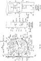
- Fig. 4A is a schematic side view of the manufacturing apparatus 30 of the present embodiment.
- Fig. 4B is a view along arrows B-B in Fig. 4A.
- Fig. 4C is a view along arrows C-C in Fig. 4A .
- Fig. 5A is a schematic plan view of a holding pad 51 viewed from a holding surface 51s.
- Fig. 5B is a view along arrows B-B in Fig. 5A.
- Fig. 5C is a view along arrows C-C in Fig. 5A .
- Fig. 6 is a schematic side view illustrating a receiving position Pin and an arrangement position of the laser cutter 71 in this manufacturing apparatus 30 in an enlarged manner.
- a width direction of the manufacturing line is also referred to as a "CD direction,” and a direction perpendicular to this CD direction is also referred to as a "MD direction.” That is, the MD direction is referred to as any direction in a planar surface perpendicular to the CD direction.
- the intermediate product 1m of the diaper 1 is conveyed taking the MD direction as the direction of conveyance.
- a vertical direction is also referred to as an "up and down direction”
- a horizontal direction is also referred to as a "front-rear direction.”
- a continuous body 10a of an absorbent main body (equivalent to the continuous-sheet-like member) formed by connecting a plurality of absorbent main bodies 10, 10, ... in the lengthwise direction is cut off by the laser cutter 71 to produce a single-sheet absorbent main body 10 (equivalent to the single-sheet workpiece), and the produced absorbent main body 10 is extended across and bonded to a pair of band-member continuous bodies 20a, 24a (equivalent to the continuous sheet).
- an approximately ladder-type member 1m (equivalent to the composite body of the continuous-sheet) as in Fig. 4C is manufactured as the intermediate product 1m of the diaper 1.
- the pair of band members 20, 24 at the time being supplied to this manufacturing apparatus 30 are conveyed, in forms of the continuous bodies 20a, 24a along the MD direction, along a continuous direction of these continuous bodies 20a, 24a, and in a state aligned in parallel with an interval between one another in the CD direction.
- the absorbent main body 10 is also conveyed, in a form of a continuous body 10a that is continuous in the MD direction, along a continuous direction of this continuous body 10a. That is, the top sheet 12, the back sheet 13, and the pair of barrier cuff sheets 14, 14 that constitute the absorbent main body 10 are each in a state of a continuous sheet that is continuous in the MD direction. Then, the absorbent core 11 interposed between the respective continuous sheets of these top sheet 12 and back sheet 13 is in a state aligned with an interval between the absorbent cores 11 adjacent to one another in the MD direction. Then, these respective continuous sheets are in a state mutually integrally bonded to the continuous sheet or the absorbent core 11 that are mutually adjacent in the thickness direction by an adhesion or similar material.
- the manufacturing apparatus 30 includes a rotating drum 31.
- the rotating drum 31 is driven to rotate around a rotation shaft C31 along the CD direction.
- the rotating drum 31 has an outer periphery portion on which a plurality of holding pads 51, 51, ... (equivalent to the holding members) are disposed aligned in a direction of rotation Dc31 (equivalent to the circulating direction) of the rotating drum 31.
- the plurality of holding pads 51, 51, ... obtains rotation force from rotating movement of the rotating drum 31. This circulates the plurality of holding pads 51, 51, ... taking a circulating trajectory Tr having a precise circle shape centering the above-described rotation shaft C31 as one direction (clockwise in the example in Fig. 4A ).
- Each holding pad 51 has the holding surface 51s that generates absorbing force.
- This holding surface 51s faces an outside in a rotation radial direction Dr of the circulating trajectory Tr.
- the above-described continuous body 10a of the absorbent main body is conveyed toward the receiving position Pin set on the circulating trajectory Tr. Accordingly, when the respective holding pads 51, 51, ... pass through this receiving position Pin, the respective holding pads 51, 51, ... receive one surface of the continuous body 10a of the absorbent main body by adsorption of the holding surfaces 51s and hold it on these surfaces 51s.
- the laser cutter 71 is disposed at a downstream position of the receiving position Pin on the circulating trajectory Tr. Then, when a boundary position BL51 of the holding pads 51, 51 adjacent to one another in the direction of rotation Dc31 passes through the location of the laser cutter 71, a part 10ac corresponding to the above-described boundary position BL51 in the continuous body 10a of the absorbent main body is irradiated with the laser beam from the laser cutter 71. This cuts off a downstream part 10ad of the boundary position BL51 from the continuous body 10a of the absorbent main body. As a result, a single-sheet absorbent main body 10 is produced on the holding pad 51. Then, this holding pad 51 remains to hold the absorbent main body 10 on the holding surface 51s to move to a further downstream delivery position Pout on the circulating trajectory Tr.
- the holding pad 51 rotates at 90° around an approximately plane center C51s of the holding surface 51s.
- the absorbent main body 10 on the holding surface 51s also rotates at 90° around the approximately plane center C51s.
- the lengthwise direction of the absorbent main body 10 is changed from the MD direction to the CD direction.
- the absorbent main body 10 has a posture configured to be extended across the pair of band-member continuous bodies 20a, 24a.
- a pitch P51 (not illustrated in any drawings) between the holding pads 51, 51 adjacent to one another is enlarged. Its purpose is to prevent interference of the holding pads 51, 51 one another that possibly occurs when the one holding pad 51 rotates, and to adjust the above-described pitch 51 to a size of a mounting pitch P10 ( Fig. 4C ) when the absorbent main body 10 is bonded to and mounted on the pair of band-member continuous bodies 20a, 24a at the delivery position Pout, which is described below.
- the pitch P51 between the holding pads 51, 51 is reduced to return to the original pitch P51.
- the holding pad 51 rotates at 90°. This returns the direction of this pad 51 to the original direction before the holding pad 51 arrives at the receiving position Pin.
- the former change of this pitch P51 is performed by a repitch mechanism, and the latter rotation is performed, for example, by appropriate driving sources such as motors or cam mechanisms provided for each holding pad 51. The repitch mechanism will be described later.
- a conveying roller 82 (equivalent to the bonding device) that guides travel of the pair of band-member continuous bodies 20a, 24a is disposed. Then, when the holding pad 51 passes through this delivery position Pout, the conveying roller 82 presses the pair of band-member continuous bodies 20a, 24a to the absorbent main body 10 held onto the holding pad 51. This bonds the respective end portions 10e, 10e in the CD direction of the absorbent main body 10 to the continuous bodies 20a, 24a of the pair of band members 20, 24a respectively.
- the absorbent main body 10 is delivered to the pair of band-member continuous bodies 20a, 24a from the holding pad 51 to produce the approximately ladder-type intermediate product 1m as in Fig. 4C . That is, the approximately ladder-type intermediate product 1m obtained by bonding the plurality of absorbent main bodies 10, 10, ... on the pair of band-member continuous bodies 20a, 24a at a predetermined pitch in the MD direction is produced.
- the rotating drum 31 is driven to rotate around the rotation shaft C31 along the CD direction taking a servo motor or similar motor (not illustrated) as the driving source.
- a plurality of arm members 33a, 33a, ... are supported swingably around a predetermined fulcrum at intervals of a predetermined angle in the direction of rotation Dc31 of the rotating drum 31.
- each arm member 33a has a swing end coupled to a corresponding holding pad 51 via an appropriate link member 33r.
- Each holding pad 51 is guided to circulate along the above-described circulating trajectory Tr having the precise circle shape by an appropriate guiding member (not illustrated) such as a guiding rail having a precise circle shape fixed to a ground or the like. Accordingly, when the rotating drum 31 performs the rotating movement in one direction, the respective holding pads 51, 51, ... obtain rotation force from this rotating movement to circulate along the circulating trajectory Tr in one direction (clockwise in the example in Fig. 4A ) in conjunction with the rotating drum 31.
- an appropriate guiding member such as a guiding rail having a precise circle shape fixed to a ground or the like.
- the holding surface 51s of the holding pad 51 has a longitudinal direction and a width direction corresponding to a planar shape of the absorbent main body 10 in order to ensure holding of the absorbent main body 10 from end to end. Then, in order to smoothly receive the continuous body 10a of the absorbent-main-body at the receiving position Pin, a shape when the holding pad 51 is viewed from the width direction is, for example, as illustrated in Fig. 5B , an approximately equilateral trapezoidal shape whose center portion in the longitudinal direction projects to the outside of the rotation radial direction Dr compared with both end portions.
- a shape when the holding pad 51 is viewed from the longitudinal direction is, for example, as illustrated in Fig. 5C , an approximately arc shape whose center portion in the width direction projects to the outside of the rotation radial direction Dr compared with both end portions.
- the rotating drum 31 has the repitch mechanism that changes the pitch P51 between the holding pads 51, 51 adjacent to one another in the direction of rotation Dc31.
- the holding pad 51 causes the longitudinal direction of the holding surface 51s to be along the circulating trajectory Tr to pass through this receiving position Pin in a state where a clearance S between the holding pads 51, 51 has been reduced to 3 mm or less.
- the holding pad 51 absorbs and holds the continuous body 10a of the absorbent-main-body on the holding surface 51s.
- the holding pad 51 can fixedly hold the absorbent main body 10, which will be produced later by being cut off from the continuous body 10a of the absorbent main body by the laser cutter 71, up to both end portions 10e, 10e in the direction of rotation Dc31 of the holding pad 51. This can surely reduce the deformation such as unintended turning up and replicating of the absorbent main body 10 even at these both end portions 10e, 10e.
- the pad 51 can fixedly hold the absorbent main body 10 up to both end portions 10e, 10e through the reduction of the clearance S between the holding pads 51, 51 as described above. Accordingly, this can surely reduce the deformation such as turning up and replicating of these both end portions 10e, 10e.
- the continuous body 10a of the absorbent main body is stretchable in the MD direction based on the elastic member 17 of the leg gather and the elastic member 15 of the barrier cuff 14g disposed on the continuous body 10a of the absorbent main body itself. Then, at the receiving position Pin, these elastic members 15, 17 are in extended states in the MD direction. Therefore, as in Fig.
- the holding pad 51 can hold the continuous body 10a of the absorbent main body almost over the boundary position BL51 between the holding pads 51, 51.
- This can fixedly hold the absorbent main body 10, which is produced on the holding pad 51 after being cut off at this boundary position BL51, up to both end portions 10e, 10e. Then, as a result, contraction deformation of these both end portions 10e, 10e can be also surely reduced.
- a ring groove is formed as a face cam.
- Engaging elements such as cam followers (not illustrated) to be engaged with this ring groove are disposed on the respective arm members 33a, 33a, ... of Fig. 4A .
- a cam curve having a shape of the ring groove is configured to a shape corresponding to moving patterns of enlargement and reduction of the above-described pitch P51.
- the arm member 33a performs swing movement corresponding to respective rotation positions in the direction of rotation Dc31 of the rotating drum 31 by the engagement of the ring groove as the face cam with the engaging element. This results in achievement of the change of the pitch P51 between the holding pads 51, 51 adjacent to one another.
- the achievement of the repitch mechanism is not limited to the cam member in any way.
- the above-described repitch mechanism may be achieved by disposing a guiding member that guides the respective holding pads 51, 51, ... relatively movably in a predetermined range in the direction of rotation Dc31 with respect to the rotating drum 31 and by disposing servo motors for driving of the relative movement in the above-described predetermined range on the respective holding pads 51, 51, ....
- the above-described generation of the absorbing force of the holding surface 51s can be achieved, for example, by intake action from a plurality of intake holes 51h, 51h, ... disposed over an approximately whole surface of the holding surface 51s as in Fig. 5A to Fig. 5C .
- this intake action can be achieved, for example, by compartmentally forming a pressure chamber SP51 communicated with the intake holes 51h, 51h, ... inside the holding pad 51 and by coupling the above-described pressure chamber SP51 to a negative-pressure source (not illustrated) such as a blower or a compressor via an appropriate pipe member (not illustrated).
- a negative-pressure source such as a blower or a compressor
- the location of the intake holes 51h is not limited to the approximately whole surface of the holding surface 51s as described above in any way.
- the intake holes 51h may be disposed only at respective edge portions of the four sides of the holding surface 51s and their proximity parts without disposing the intake holes 51h at a proximity part of the approximately plane center C
- the state where the clearance S has been reduced is maintained until when the boundary position BL51 between the holding pads 51, 51 passes through the location of the laser cutter 71. Further, this reduced state is at least maintained while the continuous body 10a of the absorbent main body is irradiated with laser beam. Accordingly, in this state where the clearance S has been reduced, the laser cutter 71 irradiates the irradiation target part 10ac corresponding to the above-described boundary position BL51 in the continuous body 10a of the absorbent main body with laser beam. This cuts off the downstream part 10ad from the continuous body 10a of the absorbent main body at this part 10ac. Then, as a result, onto the holding pad 51 positioned at a downstream side of the above-described holding pads 51, 51, the above-described cut downstream part 10ad is held as the single-sheet absorbent main body 10.
- This laser cutter 71 includes an irradiation head 71h that can move a spot of the laser beam in the CD direction and the direction of rotation Dc31, and a control unit (not illustrated) that controls the irradiation head 71h. Then, when the boundary position BL51 between the holding pads 51, 51 passes through, in conjunction with this pass, the above-described spot is moved in the CD direction and the direction of rotation Dc31 to cut off the continuous body 10a of the absorbent main body along the CD direction at this boundary position BL51.
- this laser cutter 71 one having a well-known configuration is available. As its example, a two-shaft type galvanometer scanner is included.
- this galvanometer scanner includes a light source of the laser beam, a lens, and a galvanometer mirror that changes an irradiation direction of the laser beam to two directions. This ensures scan of the laser beam in two directions.
- a light source of the laser beam a lens
- a galvanometer mirror that changes an irradiation direction of the laser beam to two directions. This ensures scan of the laser beam in two directions.
- an appropriate light source is available if fusing of a cut target is possible.
- a diode type may be used, or a CO 2 type may be used.
- the irradiation head 71h of the laser cutter 71 is disposed at a position outside the rotation radial direction Dr with respect to the circulating trajectory Tr of the holding pad 51. Accordingly, from the position outside the rotation radial direction Dr with respect to the continuous body 10a of the absorbent main body, the continuous body 10a of the absorbent main body can be irradiated with the laser beam. As a result, in the irradiation of the laser beam, the holding pad 51 is effectively prevented from becoming an obstacle.
- the invention is not limited thereto. That is, if a location space is ensured, the irradiation head 71h may be disposed inside the circulating trajectory Tr.
- heat-resistant portions are disposed on the parts 51e, 51e (hatched parts in Fig. 5A ) on which the irradiation target parts 10ac of the continuous body 10a of the absorbent main body abut in the holding pad 51 and their proximity parts. That is, although only the continuous body 10a of the absorbent main body can be irradiated with the laser beam by adjustment of a focus distance of the laser beam, a dimension in the thickness direction possibly varies at the above-described irradiation target parts 10ac.
- the parts 51e, 51e on which the above-described irradiation target parts 10ac abut in the holding pad 51 is also possibly irradiated with the laser beam through the continuous body 10a of the absorbent main body. Therefore, if the heat-resistant portion is disposed at this part 51e, if by any chance the part 51e is irradiated with the laser beam, thermal damage such as erosion caused by this can be reduced.
- both ends 51e, 51e in the holding pad 51 when passing through the laser cutter 71 correspond to the above-described abutted parts 51e. Therefore, the heat-resistant portion is each disposed at these both end portions 51e, 51e.
- This installation of the heat-resistant portions may be achieved by performing a thermal process such as application of a heat-resistant inorganic-system coating agent on the above-described parts 51e of the holding pad 51, or may be achieved by mounting liner members, for example, made of heat-resistant steel, made of heat-resistant alloy, and made of ceramic instead of the above-described parts 51e.
- the absorbent article may be a disposable diaper for animal other than the human, such as a pet.
- the absorbent article may be a two-piece type disposable diaper.
- this absorbent article may be a diaper with a type including an exterior sheet having a front portion, a crotch portion, and a back portion as a first component and including the absorbent main body 10 fixed to a skin side surface of this exterior sheet as a second component.
- the continuous body 10a of the absorbent main body and the absorbent main body 10 correspond to "the continuous-sheet-like member" and "the single-sheet workpiece” respectively.
- the continuous sheet will correspond to a continuous body of an exterior-sheet (a continuous body obtained by coupling a plurality of the above-described exterior sheets).
- the shape of the cutting line when the continuous body 10a of the absorbent main body is cut is a straight line along the CD direction, this should not be construed in a limiting sense by any means. That is, the shape may be a curved line such as a circular arc, or may be a complicated shape with a combination of a curved line and a straight line.
Landscapes
- Health & Medical Sciences (AREA)
- Engineering & Computer Science (AREA)
- Vascular Medicine (AREA)
- Epidemiology (AREA)
- Biomedical Technology (AREA)
- Heart & Thoracic Surgery (AREA)
- Manufacturing & Machinery (AREA)
- Life Sciences & Earth Sciences (AREA)
- Animal Behavior & Ethology (AREA)
- General Health & Medical Sciences (AREA)
- Public Health (AREA)
- Veterinary Medicine (AREA)
- Mechanical Engineering (AREA)
- Absorbent Articles And Supports Therefor (AREA)
Abstract
Description
- The present invention relates to a manufacturing method and manufacturing apparatus for a composite body of a continuous-sheet associated with an absorbent article such as disposable diapers.
- Conventionally, in a manufacturing line of absorbent articles such as disposable diapers, a continuous-sheet-like member that is continuously conveyed is cut off to produce a single-sheet workpiece, and then, this single-sheet workpiece is bonded to another continuous sheet to manufacture a composite body of a continuous-sheet.
- Patent Literature 1:
WO2005-075163 - Such a
composite body 101m of a continuous-sheet is manufactured, for example, using a rotatingdrum 131.Fig. 1A is a schematic side view of the rotatingdrum 131.Fig. 1B is a view along arrows B-B inFig. 1A .Fig. 2 is a schematic side view illustrating a receiving position Pin and an arrangement position of acutter roll 171 in an enlarged manner. - The rotating
drum 131 includes a plurality of holdingmembers holding member 151 receives and holds a continuous sheet-like member 110a, which is described above, when eachholding member 151 passes through the receiving position Pin on the circulating trajectory Tr. At a downstream position of the receiving position Pin, thecutter roll 171 that rotates at this position is disposed. Thiscutter roll 171 has an outer peripheral surface on which a cutter blade 171cu as an upper blade 171cu is formed to project. A lower blade 131cd is disposed between theholding members cutter roll 171 in accordance with circulating movement of theholding member 151, the upper blade 171cu is opposed to the lower blade 131cd by a rotation of thecutter roll 171, and then, these upper blade 171cu and lower blade 131cd cooperatively sandwich the continuous-sheet-like member 110a. Then, this cuts the continuous-sheet-like member 110a at a position between theholding members sheet workpiece 110 on theholding member 151. Thus, the single-sheet workpiece 110 held onto theholding member 151 is conveyed to a delivery position Pout at a further downstream on the circulating trajectory Tr. Until when the single-sheet workpiece 110 reaches this delivery position Pout, in some cases, a direction of the single-sheet workpiece 110 is changed by a 90° rotation of theholding member 151, and a pitch P151 between theholding members sheet workpiece 110 held onto theholding member 151 passes through this delivery position Pout, the single-sheet workpiece 110 is bonded tocontinuous sheets sheets composite body 101m of the continuous-sheet is manufactured. - Here, in a case of a mechanically cutter device using the upper blade 171cu and the lower blade 131cd, such as the above-described
cutter roll 171, as described above, the lower blade 131cd is disposed between theholding members Fig. 2 , this cannot make a clearance S between theseholding members like member 110a is widely generated between theseholding members holding member 151 cannot fixedly holdend portions sheet workpiece 110. As a result, this possibly generates unintended deformation, for example, that theseend portions 110e get wrinkles and are turned up. Then, if the single-sheet workpiece 110 is bonded to the above-describedcontinuous sheets composite body 101m of the continuous-sheet is reduced. - The present invention has been made in consideration of the conventional problems as described above. An object of the present invention is to prevent reduction of manufacturing quality of a composite body of a continuous-sheet associated with an absorbent article.
- A primal invention to achieve the above-mentioned object is a method for manufacturing a composite body of a continuous sheet associated with an absorbent article by producing a single-sheet workpiece from a continuous-sheet-like member that is continuously conveyed and by bonding the single-sheet workpiece to a continuous sheet, the method including:
- receiving and holding the continuous-sheet-like member with a plurality of holding members when each of the plurality of holding members that circulates along a circulating trajectory and is aligned in a circulating direction passes through a receiving position on the circulating trajectory;
- producing the single-sheet workpiece by irradiating the continuous-sheet-like member with laser beam while the holding members hold the continuous-sheet-like member, so as to cut off a part held onto the holding members in the continuous-sheet-like member; and
- bonding and delivering the single-sheet workpiece to the continuous sheet when the single-sheet workpiece held onto the holding member passes through a delivery position on the circulating trajectory.
- Further, a primal invention to achieve the object is an apparatus for manufacturing a composite body of a continuous sheet associated with an absorbent article by producing a single-sheet workpiece from a continuous-sheet-like member that is continuously conveyed and by bonding the single-sheet workpiece to a continuous sheet, the apparatus including:
- a plurality of holding members that circulates along a circulating trajectory and is aligned in a circulating direction, each of the plurality of holding members receiving and holding the continuous-sheet-like member when passing through a receiving position on the circulating trajectory;
- a laser cutter that cuts off a part held onto the holding members in the continuous-sheet-like member to produce the single-sheet workpiece by irradiating the continuous-sheet-like member with laser beam; and
- a bonding device that bonds the single-sheet workpiece to the continuous sheet when the single-sheet workpiece held onto the holding member passes through a delivery position on the circulating trajectory.
- Other features of the present invention will become apparent from the description in this specification and the attached drawings.
- The present invention can prevent the reduction of the manufacturing quality of the composite body of the continuous-sheet associated with the absorbent article.
-
- [
Fig. 1] Fig. 1A is a schematic side view of a rotatingdrum 131 for describing a conventional problem, andFig. 1B is a view along arrows B-B inFig. 1A . - [
Fig. 2] Fig. 2 is a schematic side view illustrating a receiving position Pin and an arrangement position of acutter roll 171 in the above-described rotatingdrum 131 in an enlarged manner. - [
Fig. 3] Fig. 3A is a schematic plan view of a developed state of a diaper 1 that is manufactured using amanufacturing apparatus 30 of the present embodiment,Fig. 3B is a cross-sectional view taken along B-B inFig. 3A, and Fig. 3C is a schematic perspective view of the diaper 1 when it is worn. - [
Fig. 4] Fig. 4A is a schematic side view of themanufacturing apparatus 30 in the preset embodiment,Fig. 4B is a view along arrows B-B inFig. 4A, and Fig. 4C is a view along arrows C-C inFig. 4A . - [
Fig. 5] Fig. 5A is a schematic plan view of aholding pad 51 viewed from aholding surface 51s,Fig. 5B is a view along arrows B-B inFig. 5A, and Fig. 5C is a view along arrows C-C inFig. 5A . - [
Fig. 6] Fig. 6 is a schematic side view illustrating a receiving position Pin and an arrangement position of a laser cutter 71 in the above-describedmanufacturing apparatus 30 in an enlarged manner. - At least the following matters will be made clear by the description in the present specification and the accompanying drawings.
- A method for manufacturing a composite body of a continuous sheet associated with an absorbent article by producing a single-sheet workpiece from a continuous-sheet-like member that is continuously conveyed and by bonding the single-sheet workpiece to a continuous sheet, the method including:
- receiving and holding the continuous-sheet-like member with a plurality of holding members when each of the plurality of holding members that circulates along a circulating trajectory and is aligned in a circulating direction passes through a receiving position on the circulating trajectory;
- producing the single-sheet workpiece by irradiating the continuous-sheet-like member with laser beam while the holding members hold the continuous-sheet-like member, so as to cut off a part held onto the holding members in the continuous-sheet-like member; and
- bonding and delivering the single-sheet workpiece to the continuous sheet when the single-sheet workpiece held onto the holding member passes through a delivery position on the circulating trajectory.
- With the method for manufacturing a composite body of a continuous sheet associated with an absorbent article, the single-sheet workpiece is produced by irradiating the continuous sheet with the laser beam so as to be cut off from the continuous-sheet-like member. Accordingly, the lower blade, which is required to be disposed at a position at the proximity of the holding member in the case of the mechanically cutter device that cuts with the upper blade and the lower blade, can be omitted. Then, this can reduce the clearance between the holding members adjacent to one another in the circulating direction of the circulating trajectory, at the above-described receiving position. As a result, these holding members can receive the continuous-sheet-like member in a state where the interval between these holding members is narrowed so as to mostly contact with one another in the circulating direction. That is, the region that is possibly generated between these holding members and cannot hold the continuous-sheet-like member can be reduced. As a result, the holding member can hold the single-sheet workpiece up to almost both its end portions. Then, this can bond the single-sheet workpiece to the above-described continuous sheet while effectively reducing the unintended deformation of the single-sheet workpiece also at the above-mentioned both end portions. From the above results, the reduction of the manufacturing quality of the composite body of the continuous sheet can be prevented.
- In the method for a composite body of a continuous sheet associated with an absorbent article, it is preferable that the continuous-sheet-like member is stretchable, and
the holding member receives the continuous-sheet-like member in an extended state in the circulating direction at the receiving position. - With the method for manufacturing a composite body of a continuous sheet associated with an absorbent article, operational advantage of the above-described deformation reduction of the single-sheet workpiece can be considerably enjoyed. That is, if the clearance between the holding members cannot be reduced at the receiving position, the above-described both end portions in the single-sheet workpiece cannot be held by the holding member. Thus, these both end portions contract and deform such as getting wrinkles based on their stretch. However, on this point, with the above-described manufacturing method, the clearance between the holding members can be reduced by the amount corresponding to the above-described omission of the lower blade. This can fixedly hold the single-sheet workpiece up to both ends. Then, as a result, while the contraction deformation of these both end portions is reduced, the single-sheet workpiece can be bonded to the above-described continuous sheet.
- In the method for manufacturing a composite body of a continuous sheet associated with an absorbent article,
it is preferable that before the single-sheet workpiece in a state held onto the holding member reaches the delivery position, a direction of the single-sheet workpiece is changed by a rotation of the holding member. - With the method for manufacturing a composite body of a continuous sheet associated with an absorbent article, operational advantage of the above-described deformation reduction of the single-sheet workpiece can be considerably enjoyed. That is, if the clearance between the holding members cannot be reduced at the receiving position, the above-described both end portions in the single-sheet workpiece cannot be held by the holding member, thus possibly causing these both end portions to be turned up and/or replicate by wind pressure caused by the rotation of the holding member that may further acts in addition to wind pressure caused by the circulating movement. However, on this point, with the above-described manufacturing method, the clearance between the holding members can be reduced by the amount corresponding to the above-described omission of the lower blade. This can fixedly hold the single-sheet workpiece up to both end portions. Then, as a result, while the turn-up and the replication of these both end portions are reduced, the single-sheet workpiece can be bonded to the above-described continuous sheet.
- In the method for manufacturing a composite body of a continuous sheet associated with an absorbent article,
it is preferable that when a boundary position between the holding members adjacent to one another in the circulating direction passes through the receiving position, a clearance between the holding members has been reduced to 3 mm or less. - With the method for manufacturing a composite body of a continuous sheet associated with an absorbent article, when the boundary position between the holding members adjacent to one another in the circulating direction passes through the receiving position, these holding members are in a state where the clearance between the holding members one another has been reduced to 3 mm or less. Accordingly, the region that cannot hold the continuous-sheet-like member can be almost eliminated. The region is possibly generated between these holding members. Thereby, the holding member can hold the single-sheet workpiece up to both end portions. As a result, while the unintended deformation of the single-sheet workpiece is surely reduced also at the above-described both end portions, the single-sheet workpiece can be bonded to the above-described continuous sheet.
- In the method for manufacturing a composite body of a continuous sheet associated with an absorbent article,
it is preferable that between the delivery position and the receiving position, a pitch between the holding members adjacent to one another in the circulating direction is changed to reduce the clearance between the holding members to 3 mm or less. - With the method for manufacturing a composite body of a continuous sheet associated with an absorbent article, when the above-described boundary position passes through the receiving position, the state where the clearance between the holding members adjacent to one another in the circulating direction has been reduced to 3 mm or less can be ensured.
- In the method for manufacturing a composite body of a continuous sheet associated with an absorbent article,
it is preferable that a state where the clearance between the holding members has been reduced to 3 mm or less is at least maintained while the continuous-sheet-like member is irradiated with the laser beam, and
a part corresponding to the boundary position in the continuous-sheet-like member is irradiated with the laser beam to cut off the continuous-sheet-like member. - With the method for manufacturing a composite body of a continuous sheet associated with an absorbent article, the continuous-sheet-like member is cut off in the state where the clearance between the above-described holding members has been reduced to 3 mm or less. Accordingly, the holding member can surely hold the single-sheet workpiece, which is produced by this cut, up to its both end portions.
- In the method for manufacturing a composite body of a continuous sheet associated with an absorbent article,
it is preferable that the holding member holds the continuous-sheet-like member on a holding surface that faces outside of the circulating trajectory, and
the continuous-sheet-like member is irradiated with the laser beam from a laser cutter disposed outside the circulating trajectory. - With the method for manufacturing a composite body of a continuous sheet associated with an absorbent article, while the continuous-sheet-like member is irradiated with the laser beam, the holding member can be promptly avoided from becoming a hindrance. That is, the above-described continuous-sheet-like member is positioned outside the circulating trajectory with respect to the holding member. Here, the laser cutter is also disposed outside the circulating trajectory. Accordingly, the laser cutter can irradiate with the laser beam from the outside of the continuous sheet. As a result, in this irradiation, the holding member can be promptly avoided from becoming the hindrance.
- In the method for manufacturing a composite body of a continuous sheet associated with an absorbent article,
it is preferable that an irradiation target part in the continuous-sheet-like member is irradiated with the laser beam,
the irradiation target part is positioned between the holding members adjacent to one another in the circulating direction, and
at least both end portions in the circulating direction in the holding member when being irradiated with the laser beam include heat-resistant portions. - With the method for manufacturing a composite body of a continuous sheet associated with an absorbent article, the heat-resistant portions are provided at the above-described both end portions in the holding member. Accordingly, even if by any chance the above-described both end portions of the holding member are irradiated with a part of the laser beam that cuts off the continuous-sheet-like member, thermal damage at both end portions caused by this can be effectively reduced.
- Further, an apparatus for manufacturing a composite body of a continuous sheet associated with an absorbent article by producing a single-sheet workpiece from a continuous-sheet-like member that is continuously conveyed and by bonding the single-sheet workpiece to a continuous sheet, the apparatus including:
- a plurality of holding members that circulates along a circulating trajectory and is aligned in a circulating direction, each of the plurality of holding members receiving and holding the continuous-sheet-like member when passing through a receiving position on the circulating trajectory;
- a laser cutter that cuts off a part held onto the holding members in the continuous-sheet-like member to produce the single-sheet workpiece by irradiating the continuous-sheet-like member with laser beam; and
- a bonding device that bonds the single-sheet workpiece to the continuous sheet when the single-sheet workpiece held onto the holding member passes through a delivery position on the circulating trajectory.
- With the apparatus for manufacturing a composite body of a continuous sheet associated with the absorbent article, operational advantages similar to those in the case of the above-described manufacturing method can be provided.
- A method for manufacturing a
composite body 1m of a continuous-sheet of the present embodiment and amanufacturing apparatus 30 are used, for example, in a manufacturing line of a disposable diaper 1. -
Fig. 3A to Fig. 3C are explanatory views of the disposable diaper 1.Fig. 3A is a schematic plan view of the diaper 1 in a developed state,Fig. 3B is a cross-sectional view taken along B-B inFig. 3A, and Fig. 3C is a schematic perspective view of the diaper 1 when it is worn. - This diaper 1, in the developed state in
Fig. 3A , has a lengthwise direction, a lateral direction, and a thickness direction as three directions that are mutually orthogonal. This diaper 1 is what is called a three-piece type diaper, thus including afront band member 20, aback band member 24, and an absorbentmain body 10. Thefront band member 20 covers a front portion of a wearer. Theback band member 24 covers a back portion of the wearer. The absorbentmain body 10 is placed on a crotch of the wearer to absorb bodily fluid such as urine. Then, in this developed state, in a state where thefront band member 20 and theback band member 24 are mutually aligned in parallel along the lateral direction with a space in the lengthwise direction between them, the absorbentmain body 10 is bridged between thefront band member 20 and theback band member 24, and bothend portions main body 10 are bonded and fixed tonearest band members - Here, from this developed state, the diaper 1 is folded in two taking an approximately center portion C10 in the lengthwise direction of the absorbent
main body 10 as a folding position, and theband members sites band members waist opening 3 and a pair ofleg openings Fig. 3C . - As illustrated in
Fig. 3A and Fig. 3B , the absorbentmain body 10 includes anabsorbent core 11, atop sheet 12, and aback sheet 13. Theabsorbent core 11 is obtained by forming liquid absorbent material such as pulp fiber and superabsorbent polymer (what is called SAP) into a predetermined shape such as an approximately rectangular shape in a plan view. Thetop sheet 12 covers theabsorbent core 11 from a skin side of the wearer. Theback sheet 13 covers theabsorbent core 11 from a non skin side. Thetop sheet 12 is, for example, a fluid-permeable nonwoven fabric having a plane size larger than that of theabsorbent core 11. Theback sheet 13 is, for example, a fluid-impermeable sheet also having a plane size larger than that of theabsorbent core 11. As its example, a fluid-impermeable leak-proof sheet such as polyethylene and a laminated sheet obtained by sticking this leak-proof sheet and an exterior sheet such as a nonwoven fabric (not illustrated) together are included. Then, in a state where thesetop sheet 12 and backsheet 13 sandwich theabsorbent core 11, for example, at parts that projects outside from four sides of theabsorbent core 11, thetop sheet 12 and theback sheet 13 are bonded to one another in a frame shape. This forms the absorbentmain body 10. Theabsorbent core 11 may be coated with a fluid-permeable sheet (not illustrated) such as tissue paper. - As illustrated in
Fig. 3B ,elastic members 17 such as elastic strings along the lengthwise direction are secured to parts that project outside in the lateral direction with respect to theabsorbent core 11 in the absorbentmain body 10, for example, by a hot-melt adhesive in a stretched state in this lengthwise direction. Then, this adds stretch to these parts. Here, these parts are parts that will be theleg openings 5 of the diaper 1. Accordingly, if the stretched state of these parts is released, these parts contract in the lengthwise direction to form a plurality of pleats. Thus, these pleats become leg gathers of therespective leg openings - Further, in some cases, as this example, respective end portions in the lateral direction at the
top sheet 12 may includebarrier cuffs sheet 12 to prevent side leakage. Therespective barrier cuffs 14g are formed by respective barrier cuff sheets 14 fixed to the respective end portions in the lateral direction of thetop sheet 12 via fixed portions k. That is, anelastic member 15 such as an elastic string is fixed in the stretched state in the lengthwise direction to aninside part 14i in the lateral direction with respect to the above-described fixed portion k in this sheet 14. Then, when this stretched state is released, thisinside part 14i contracts in the lengthwise direction, and thus theinside part 14i stands while forming a plurality of pleats. As a result, thisinside part 14i functions as thebarrier cuff 14g. The above-described fixed portion k is formed, for example, by a hot-melt adhesive. - The
front band member 20 and theback band member 24 are both made of a soft sheet material such as nonwoven fabric. Here, as illustrated inFig. 3B , therespective band members nonwoven fabrics respective band members respective end portions main body 10 respectively. Elastic members (not illustrated) such as elastic strings are fixed to therespective band members band members - Such diaper 1 is manufactured in the manufacturing line. In this line, the
intermediate product 1m of the diaper 1 is conveyed along a predetermined direction of conveyance. Then, during this conveyance, various kinds of processes are performed on thisintermediate product 1m. Each time the respective processes are performed, a form of theintermediate product 1m is sequentially changed, and finally the diaper 1 as inFig. 3C is completed. The manufacturing method and themanufacturing apparatus 30 of the present embodiment undertake one of the processes. -
Fig. 4A is a schematic side view of themanufacturing apparatus 30 of the present embodiment.Fig. 4B is a view along arrows B-B inFig. 4A. Fig. 4C is a view along arrows C-C inFig. 4A .Fig. 5A is a schematic plan view of aholding pad 51 viewed from a holdingsurface 51s.Fig. 5B is a view along arrows B-B inFig. 5A. Fig. 5C is a view along arrows C-C inFig. 5A . Further,Fig. 6 is a schematic side view illustrating a receiving position Pin and an arrangement position of the laser cutter 71 in thismanufacturing apparatus 30 in an enlarged manner. - In the following, a width direction of the manufacturing line is also referred to as a "CD direction," and a direction perpendicular to this CD direction is also referred to as a "MD direction." That is, the MD direction is referred to as any direction in a planar surface perpendicular to the CD direction. Then, the
intermediate product 1m of the diaper 1 is conveyed taking the MD direction as the direction of conveyance. In the following, among two directions that are mutually orthogonal in the MD direction, a vertical direction is also referred to as an "up and down direction," and a horizontal direction is also referred to as a "front-rear direction." - As illustrated in
Fig. 4A , in thismanufacturing apparatus 30, the following process is performed. Acontinuous body 10a of an absorbent main body (equivalent to the continuous-sheet-like member) formed by connecting a plurality of absorbentmain bodies main body 10 is extended across and bonded to a pair of band-membercontinuous bodies type member 1m (equivalent to the composite body of the continuous-sheet) as inFig. 4C is manufactured as theintermediate product 1m of the diaper 1. - The following describes the above-described process undertook by this
manufacturing apparatus 30. - First, as illustrated in
Fig. 4C , the pair ofband members manufacturing apparatus 30 are conveyed, in forms of thecontinuous bodies continuous bodies - As illustrated in
Fig. 4B , the absorbentmain body 10 is also conveyed, in a form of acontinuous body 10a that is continuous in the MD direction, along a continuous direction of thiscontinuous body 10a. That is, thetop sheet 12, theback sheet 13, and the pair of barrier cuff sheets 14, 14 that constitute the absorbentmain body 10 are each in a state of a continuous sheet that is continuous in the MD direction. Then, theabsorbent core 11 interposed between the respective continuous sheets of thesetop sheet 12 and backsheet 13 is in a state aligned with an interval between theabsorbent cores 11 adjacent to one another in the MD direction. Then, these respective continuous sheets are in a state mutually integrally bonded to the continuous sheet or theabsorbent core 11 that are mutually adjacent in the thickness direction by an adhesion or similar material. - Meanwhile, as illustrated in
Fig. 4A , themanufacturing apparatus 30 includes arotating drum 31. Therotating drum 31 is driven to rotate around a rotation shaft C31 along the CD direction. Therotating drum 31 has an outer periphery portion on which a plurality of holdingpads rotating drum 31. The plurality of holdingpads rotating drum 31. This circulates the plurality of holdingpads Fig. 4A ). - Each holding
pad 51 has the holdingsurface 51s that generates absorbing force. This holdingsurface 51s faces an outside in a rotation radial direction Dr of the circulating trajectory Tr. The above-describedcontinuous body 10a of the absorbent main body is conveyed toward the receiving position Pin set on the circulating trajectory Tr. Accordingly, when therespective holding pads respective holding pads continuous body 10a of the absorbent main body by adsorption of the holding surfaces 51s and hold it on thesesurfaces 51s. - The laser cutter 71 is disposed at a downstream position of the receiving position Pin on the circulating trajectory Tr. Then, when a boundary position BL51 of the
holding pads continuous body 10a of the absorbent main body is irradiated with the laser beam from the laser cutter 71. This cuts off a downstream part 10ad of the boundary position BL51 from thecontinuous body 10a of the absorbent main body. As a result, a single-sheet absorbentmain body 10 is produced on theholding pad 51. Then, thisholding pad 51 remains to hold the absorbentmain body 10 on the holdingsurface 51s to move to a further downstream delivery position Pout on the circulating trajectory Tr. - In this process to move to the delivery position Pout, the holding
pad 51 rotates at 90° around an approximately plane center C51s of the holdingsurface 51s. Thus, the absorbentmain body 10 on the holdingsurface 51s also rotates at 90° around the approximately plane center C51s. As a result, the lengthwise direction of the absorbentmain body 10 is changed from the MD direction to the CD direction. Thereby, the absorbentmain body 10 has a posture configured to be extended across the pair of band-membercontinuous bodies - Similarly, in this process to move to the delivery position Pout, a pitch P51 (not illustrated in any drawings) between the holding
pads holding pads holding pad 51 rotates, and to adjust the above-describedpitch 51 to a size of a mounting pitch P10 (Fig. 4C ) when the absorbentmain body 10 is bonded to and mounted on the pair of band-membercontinuous bodies - On the other hand, in a process to move from this delivery position Pout to the receiving position Pin after passing through this delivery position Pout, the pitch P51 between the holding
pads pad 51 rotates at 90°. This returns the direction of thispad 51 to the original direction before theholding pad 51 arrives at the receiving position Pin. Incidentally, the former change of this pitch P51 is performed by a repitch mechanism, and the latter rotation is performed, for example, by appropriate driving sources such as motors or cam mechanisms provided for each holdingpad 51. The repitch mechanism will be described later. - As illustrated in
Fig. 4C , at the delivery position Pout, a conveying roller 82 (equivalent to the bonding device) that guides travel of the pair of band-membercontinuous bodies pad 51 passes through this delivery position Pout, the conveyingroller 82 presses the pair of band-membercontinuous bodies main body 10 held onto the holdingpad 51. This bonds therespective end portions main body 10 to thecontinuous bodies band members main body 10 is delivered to the pair of band-membercontinuous bodies pad 51 to produce the approximately ladder-typeintermediate product 1m as inFig. 4C . That is, the approximately ladder-typeintermediate product 1m obtained by bonding the plurality of absorbentmain bodies continuous bodies - As described above, the process performed by this
manufacturing apparatus 30 has been described. The following describes the above-described process in more detail with the description ofrespective configurations 31, 71 included in thismanufacturing apparatus 30 and the description of distinctive matters of the present embodiment. - The
rotating drum 31 is driven to rotate around the rotation shaft C31 along the CD direction taking a servo motor or similar motor (not illustrated) as the driving source. As illustrated inFig. 4A , at the outer periphery portion of therotating drum 31, a plurality ofarm members rotating drum 31. Then, eacharm member 33a has a swing end coupled to acorresponding holding pad 51 via anappropriate link member 33r. Each holdingpad 51 is guided to circulate along the above-described circulating trajectory Tr having the precise circle shape by an appropriate guiding member (not illustrated) such as a guiding rail having a precise circle shape fixed to a ground or the like. Accordingly, when therotating drum 31 performs the rotating movement in one direction, therespective holding pads Fig. 4A ) in conjunction with therotating drum 31. - As illustrated in
Fig. 5A to Fig. 5C , the holdingsurface 51s of theholding pad 51 has a longitudinal direction and a width direction corresponding to a planar shape of the absorbentmain body 10 in order to ensure holding of the absorbentmain body 10 from end to end. Then, in order to smoothly receive thecontinuous body 10a of the absorbent-main-body at the receiving position Pin, a shape when the holdingpad 51 is viewed from the width direction is, for example, as illustrated inFig. 5B , an approximately equilateral trapezoidal shape whose center portion in the longitudinal direction projects to the outside of the rotation radial direction Dr compared with both end portions. In order to smoothly deliver the absorbentmain body 10 at the delivery position Pout, a shape when the holdingpad 51 is viewed from the longitudinal direction is, for example, as illustrated inFig. 5C , an approximately arc shape whose center portion in the width direction projects to the outside of the rotation radial direction Dr compared with both end portions. Further, therotating drum 31 has the repitch mechanism that changes the pitch P51 between the holdingpads - Then, as illustrated in
Fig. 6 , when the boundary position BL51 between the holdingpads pad 51 causes the longitudinal direction of the holdingsurface 51s to be along the circulating trajectory Tr to pass through this receiving position Pin in a state where a clearance S between the holdingpads pad 51 absorbs and holds thecontinuous body 10a of the absorbent-main-body on the holdingsurface 51s. - That is, in this embodiment, since the
continuous body 10a of the absorbent main body is cut off by the laser cutter 71, the lower blade is not disposed between the holdingpads pads Fig. 2 ) that cannot hold thecontinuous body 10a of the absorbent main body and that possibly occurs between these holdingpads pad 51 can fixedly hold the absorbentmain body 10, which will be produced later by being cut off from thecontinuous body 10a of the absorbent main body by the laser cutter 71, up to bothend portions holding pad 51. This can surely reduce the deformation such as unintended turning up and replicating of the absorbentmain body 10 even at these bothend portions - As this example, when the direction of the absorbent
main body 10 is changed by the rotation of theholding pad 51 after production of this absorbentmain body 10, operational advantage of the above-described deformation reduction of bothend portions holding pad 51 illustrated inFig. 4A , wind pressure caused by the rotation of theholding pad 51 acts on the absorbentmain body 10 absorbed by and held onto thispad 51, in addition to wind pressure caused by circulating movement in direction of rotation Dc31. As a result, turning up and replicating of bothend portions - However, on this point, in this example, the
pad 51 can fixedly hold the absorbentmain body 10 up to bothend portions pads end portions - Further, as this example, also when a processing material of the
manufacturing apparatus 30 is a member being stretchable in the MD direction like thecontinuous body 10a of the absorbent main body, the above-described operational advantage of deformation reduction can be more effectively enjoyed. That is, thecontinuous body 10a of the absorbent main body is stretchable in the MD direction based on theelastic member 17 of the leg gather and theelastic member 15 of thebarrier cuff 14g disposed on thecontinuous body 10a of the absorbent main body itself. Then, at the receiving position Pin, theseelastic members Fig. 2 , if a large clearance S is formed between the holdingpads continuous body 10a of the absorbent main body. Thereby, parts 10ae corresponding to these regions AN in thiscontinuous body 10a, that is, the parts 10ae corresponding to bothend portions main body 10 contract and deform in the MD direction to get wrinkles in accordance with the cut of thecontinuous body 10a of the absorbent main body. As a result, the absorbentmain body 10 having wrinkles at bothend portions continuous bodies - However, on this point, in this example, as in
Fig. 6 , the clearance S between the holdingpads pad 51 can hold thecontinuous body 10a of the absorbent main body almost over the boundary position BL51 between the holdingpads main body 10, which is produced on theholding pad 51 after being cut off at this boundary position BL51, up to bothend portions end portions - Now, the above-described repitch mechanism is achieved, for example, using a cam member. That is, on the cam member (not illustrated) fixed to the ground side, for example, a ring groove is formed as a face cam. Engaging elements such as cam followers (not illustrated) to be engaged with this ring groove are disposed on the
respective arm members Fig. 4A . Then, a cam curve having a shape of the ring groove is configured to a shape corresponding to moving patterns of enlargement and reduction of the above-described pitch P51. Accordingly, when therotating drum 31 performs the rotating movement, thearm member 33a performs swing movement corresponding to respective rotation positions in the direction of rotation Dc31 of therotating drum 31 by the engagement of the ring groove as the face cam with the engaging element. This results in achievement of the change of the pitch P51 between the holdingpads - However, the achievement of the repitch mechanism is not limited to the cam member in any way. For example, the above-described repitch mechanism may be achieved by disposing a guiding member that guides the
respective holding pads rotating drum 31 and by disposing servo motors for driving of the relative movement in the above-described predetermined range on therespective holding pads - The above-described generation of the absorbing force of the holding
surface 51s can be achieved, for example, by intake action from a plurality ofintake holes surface 51s as inFig. 5A to Fig. 5C . Incidentally, this intake action can be achieved, for example, by compartmentally forming a pressure chamber SP51 communicated with theintake holes pad 51 and by coupling the above-described pressure chamber SP51 to a negative-pressure source (not illustrated) such as a blower or a compressor via an appropriate pipe member (not illustrated). However, the location of theintake holes 51h is not limited to the approximately whole surface of the holdingsurface 51s as described above in any way. For example, theintake holes 51h may be disposed only at respective edge portions of the four sides of the holdingsurface 51s and their proximity parts without disposing theintake holes 51h at a proximity part of the approximately plane center C51s of the holdingsurface 51. - Meanwhile, as illustrated in
Fig. 6 , the state where the clearance S has been reduced is maintained until when the boundary position BL51 between the holdingpads continuous body 10a of the absorbent main body is irradiated with laser beam. Accordingly, in this state where the clearance S has been reduced, the laser cutter 71 irradiates the irradiation target part 10ac corresponding to the above-described boundary position BL51 in thecontinuous body 10a of the absorbent main body with laser beam. This cuts off the downstream part 10ad from thecontinuous body 10a of the absorbent main body at this part 10ac. Then, as a result, onto the holdingpad 51 positioned at a downstream side of the above-describedholding pads main body 10. - This laser cutter 71, as illustrated in
Fig. 4A , includes an irradiation head 71h that can move a spot of the laser beam in the CD direction and the direction of rotation Dc31, and a control unit (not illustrated) that controls the irradiation head 71h. Then, when the boundary position BL51 between the holdingpads continuous body 10a of the absorbent main body along the CD direction at this boundary position BL51. For this laser cutter 71, one having a well-known configuration is available. As its example, a two-shaft type galvanometer scanner is included. That is, this galvanometer scanner includes a light source of the laser beam, a lens, and a galvanometer mirror that changes an irradiation direction of the laser beam to two directions. This ensures scan of the laser beam in two directions. For the above-described light source, an appropriate light source is available if fusing of a cut target is possible. For example, a diode type may be used, or a CO2 type may be used. - As illustrated in
Fig. 4A , in this example, the irradiation head 71h of the laser cutter 71 is disposed at a position outside the rotation radial direction Dr with respect to the circulating trajectory Tr of theholding pad 51. Accordingly, from the position outside the rotation radial direction Dr with respect to thecontinuous body 10a of the absorbent main body, thecontinuous body 10a of the absorbent main body can be irradiated with the laser beam. As a result, in the irradiation of the laser beam, the holdingpad 51 is effectively prevented from becoming an obstacle. However, the invention is not limited thereto. That is, if a location space is ensured, the irradiation head 71h may be disposed inside the circulating trajectory Tr. - Preferably, as illustrated in
Fig. 5A , heat-resistant portions are disposed on theparts Fig. 5A ) on which the irradiation target parts 10ac of thecontinuous body 10a of the absorbent main body abut in theholding pad 51 and their proximity parts. That is, although only thecontinuous body 10a of the absorbent main body can be irradiated with the laser beam by adjustment of a focus distance of the laser beam, a dimension in the thickness direction possibly varies at the above-described irradiation target parts 10ac. Accordingly, theparts holding pad 51 is also possibly irradiated with the laser beam through thecontinuous body 10a of the absorbent main body. Therefore, if the heat-resistant portion is disposed at thispart 51e, if by any chance thepart 51e is irradiated with the laser beam, thermal damage such as erosion caused by this can be reduced. Incidentally, in this example, both ends 51e, 51e in theholding pad 51 when passing through the laser cutter 71 correspond to the above-described abuttedparts 51e. Therefore, the heat-resistant portion is each disposed at these bothend portions parts 51e of theholding pad 51, or may be achieved by mounting liner members, for example, made of heat-resistant steel, made of heat-resistant alloy, and made of ceramic instead of the above-describedparts 51e. - While the embodiments of the present invention are described above, the embodiments are intended for easy understanding of the present invention and are not in any way to be construed as limiting the present invention. Needless to say, the present invention may be modified and improved without departing from the scope of the invention, and equivalents thereof are also encompassed by the invention. For example, the following modifications are possible.
- While the above-described embodiment exemplifies the disposable diaper 1 used by human as the absorbent article, insofar as the absorbent article that absorbs excretory fluid, this should not be construed in a limiting sense by any means. For example, the absorbent article may be a disposable diaper for animal other than the human, such as a pet.
- While the above-described embodiment exemplifies the
continuous body 10a of the absorbent main body as the continuous-sheet-like member, exemplifies the absorbentmain body 10 as the single-sheet workpiece, and exemplifies the pair of band-membercontinuous bodies main body 10 fixed to a skin side surface of this exterior sheet as a second component. Then, also in this case, thecontinuous body 10a of the absorbent main body and the absorbentmain body 10 correspond to "the continuous-sheet-like member" and "the single-sheet workpiece" respectively. However, "the continuous sheet" will correspond to a continuous body of an exterior-sheet (a continuous body obtained by coupling a plurality of the above-described exterior sheets). - While the above-described embodiment performs both movements of the change of the pitch P51 between the holding
pads respective holding pads 51 between the receiving position Pin and the delivery position Pout as illustrated inFig. 4A , this should not be construed in a limiting sense by any means. That is, only one of both movements may be performed, or both are not necessary to be performed. - While the above-described embodiment exemplifies the conveying
roller 82 as the bonding device disposed at the delivery position Pout as illustrated inFig. 4A , this should not be construed in a limiting sense by any means. For example, a circulating endless belt may be disposed at this position Pout instead of the conveyingroller 82. Then, while the travel of the band-membercontinuous bodies continuous bodies main body 10 of theholding pad 51. - While in the above-described embodiment, the shape of the cutting line when the
continuous body 10a of the absorbent main body is cut is a straight line along the CD direction, this should not be construed in a limiting sense by any means. That is, the shape may be a curved line such as a circular arc, or may be a complicated shape with a combination of a curved line and a straight line. -
- 1 disposable diaper (absorbent article)
- 1m intermediate product (composite body of continuous sheet)
- 3 waist opening
- 5 leg opening
- 10 absorbent main body (single-sheet workpiece)
- 10a continuous body of absorbent main body (continuous-sheet-like member)
- 10ac part (irradiation target part)
- 10ad downstream part
- 10ae part
- 10e end portion
- 11 absorbent core
- 12 top sheet
- 13 back sheet
- 14 barrier cuff sheet
- 14g barrier cuff
- 14i part
- 15 elastic member
- 17 elastic member
- 20 front band member (continuous sheet)
- 20a continuous body of front-band-member (continuous sheet)
- 20e site
- 21 nonwoven fabric
- 24 back band member
- 24a continuous body of back band member (continuous sheet)
- 24e site
- 30 manufacturing apparatus
- 31 rotating drum
- 33a arm member
- 33r link member
- 51 holding pad (holding member)
- 51s holding surface
- 51e part (both end)
- 51h intake hole
- 71 laser cutter
- 71h irradiation head
- 82 conveying roller (bonding device)
- AN region that cannot hold
- Tr circulating trajectory
- S clearance
- k fixed portion
- C10 approximately center portion
- C31 rotation shaft
- C51s approximately plane center
- Pin receiving position
- Pout delivery position
- BL51 boundary position
- SP51 pressure chamber
Claims (9)
- A method for manufacturing a composite body of a continuous sheet associated with an absorbent article by producing a single-sheet workpiece from a continuous-sheet-like member that is continuously conveyed and by bonding the single-sheet workpiece to a continuous sheet, the method comprising:receiving and holding the continuous-sheet-like member with a plurality of holding members when each of the plurality of holding members that circulates along a circulating trajectory and is aligned in a circulating direction passes through a receiving position on the circulating trajectory;producing the single-sheet workpiece by irradiating the continuous-sheet-like member with laser beam while the holding members hold the continuous-sheet-like member, so as to cut off a part held onto the holding members in the continuous-sheet-like member; andbonding and delivering the single-sheet workpiece to the continuous sheet when the single-sheet workpiece held onto the holding member passes through a delivery position on the circulating trajectory.
- The method for manufacturing a composite body of a continuous sheet associated with an absorbent article according to claim 1, wherein
the continuous-sheet-like member is stretchable, and
the holding member receives the continuous-sheet-like member in an extended state in the circulating direction at the receiving position. - The method for manufacturing a composite body of a continuous sheet associated with an absorbent article according to claim 1 or 2, wherein
before the single-sheet workpiece in a state held onto the holding member reaches the delivery position, a direction of the single-sheet workpiece is changed by a rotation of the holding member. - The method for manufacturing a composite body of a continuous sheet associated with an absorbent article according to any one of claims 1 to 3, wherein
when a boundary position between the holding members adjacent to one another in the circulating direction passes through the receiving position, a clearance between the holding members has been reduced to 3 mm or less. - The method for manufacturing a composite body of a continuous sheet associated with an absorbent article according to claim 4, wherein
between the delivery position and the receiving position, a pitch between the holding members adjacent to one another in the circulating direction is changed to reduce the clearance between the holding members to 3 mm or less. - The method for manufacturing a composite body of a continuous sheet associated with an absorbent article according to claim 4 or 5, wherein
a state where the clearance between the holding members has been reduced to 3 mm or less is at least maintained while the continuous-sheet-like member is irradiated with the laser beam, and
a part corresponding to the boundary position in the continuous-sheet-like member is irradiated with the laser beam to cut off the continuous-sheet-like member. - The method for manufacturing a composite body of a continuous sheet associated with an absorbent article according to any one of claims 1 to 6, wherein
the holding member holds the continuous-sheet-like member on a holding surface that faces outside of the circulating trajectory, and
the continuous-sheet-like member is irradiated with the laser beam from a laser cutter disposed outside the circulating trajectory. - The method for manufacturing a composite body of a continuous sheet associated with an absorbent article according to any one of claims 1 to 7, wherein
an irradiation target part in the continuous-sheet-like member is irradiated with the laser beam,
the irradiation target part is positioned between the holding members adjacent to one another in the circulating direction, and
at least both end portions in the circulating direction in the holding member when being irradiated with the laser beam include heat-resistant portions. - An apparatus for manufacturing a composite body of a continuous sheet associated with an absorbent article by producing a single-sheet workpiece from a continuous-sheet-like member that is continuously conveyed and by bonding the single-sheet workpiece to a continuous sheet, the apparatus comprising:a plurality of holding members that circulates along a circulating trajectory and is aligned in a circulating direction, each of the plurality of holding members receiving and holding the continuous-sheet-like member when passing through a receiving position on the circulating trajectory;a laser cutter that cuts off a part held onto the holding members in the continuous-sheet-like member to produce the single-sheet workpiece by irradiating the continuous-sheet-like member with laser beam; anda bonding device that bonds the single-sheet workpiece to the continuous sheet when the single-sheet workpiece held onto the holding member passes through a delivery position on the circulating trajectory.
Applications Claiming Priority (2)
| Application Number | Priority Date | Filing Date | Title |
|---|---|---|---|
| JP2015030207A JP5961715B1 (en) | 2015-02-19 | 2015-02-19 | Manufacturing method and manufacturing apparatus for composite of continuous sheet according to absorbent article |
| PCT/JP2015/085477 WO2016132645A1 (en) | 2015-02-19 | 2015-12-18 | Method and apparatus for producing continuous sheet composites for absorption articles |
Publications (3)
| Publication Number | Publication Date |
|---|---|
| EP3260095A4 EP3260095A4 (en) | 2017-12-27 |
| EP3260095A1 true EP3260095A1 (en) | 2017-12-27 |
| EP3260095B1 EP3260095B1 (en) | 2018-10-17 |
Family
ID=56550484
Family Applications (1)
| Application Number | Title | Priority Date | Filing Date |
|---|---|---|---|
| EP15882746.9A Not-in-force EP3260095B1 (en) | 2015-02-19 | 2015-12-18 | Method and apparatus for producing continuous sheet composites for absorption articles |
Country Status (4)
| Country | Link |
|---|---|
| EP (1) | EP3260095B1 (en) |
| JP (1) | JP5961715B1 (en) |
| CN (1) | CN107249525A (en) |
| WO (1) | WO2016132645A1 (en) |
Families Citing this family (2)
| Publication number | Priority date | Publication date | Assignee | Title |
|---|---|---|---|---|
| JP2016154996A (en) * | 2016-06-08 | 2016-09-01 | ユニ・チャーム株式会社 | Manufacturing method and manufacturing apparatus for composite of continuous sheet according to absorbent article |
| JP7471400B2 (en) | 2019-10-22 | 2024-04-19 | エシティ・ハイジーン・アンド・ヘルス・アクチエボラグ | Pant-type garment and method for making a pant-type garment |
Family Cites Families (10)
| Publication number | Priority date | Publication date | Assignee | Title |
|---|---|---|---|---|
| US4574022A (en) * | 1984-03-05 | 1986-03-04 | H. B. Fuller Company | Apparatus and method for transferring and applying material |
| US4578133A (en) * | 1984-11-19 | 1986-03-25 | Kimberly-Clark Corporation | Method and apparatus for applying discrete strips to a web of material |
| US6682626B2 (en) * | 2001-09-14 | 2004-01-27 | Kimberly-Clark Worldwide, Inc. | Method and apparatus for assembling refastenable absorbent garments |
| US6743324B2 (en) * | 2001-09-17 | 2004-06-01 | The Procter & Gamble Company | Method for manufacturing shaped components from web materials |
| US7341087B2 (en) * | 2002-01-02 | 2008-03-11 | Kimberly-Clark Worldwide, Inc. | Apparatus for applying discrete parts to a moving web |
| BR0303717A (en) * | 2002-08-22 | 2005-04-26 | Zuiko Corp | Method and apparatus for producing garments |
| JP4420860B2 (en) * | 2005-06-09 | 2010-02-24 | 花王株式会社 | Method for manufacturing absorbent article |
| JP4573748B2 (en) * | 2005-10-25 | 2010-11-04 | 花王株式会社 | Manufacturing method of belt-like sheet |
| US9050213B2 (en) * | 2012-03-30 | 2015-06-09 | The Procter & Gamble Company | Apparatuses and methods for making absorbent articles |
| JP6189628B2 (en) * | 2013-05-13 | 2017-08-30 | 花王株式会社 | Pants-type absorbent article |
-
2015
- 2015-02-19 JP JP2015030207A patent/JP5961715B1/en active Active
- 2015-12-18 CN CN201580076351.3A patent/CN107249525A/en active Pending
- 2015-12-18 EP EP15882746.9A patent/EP3260095B1/en not_active Not-in-force
- 2015-12-18 WO PCT/JP2015/085477 patent/WO2016132645A1/en not_active Ceased
Also Published As
| Publication number | Publication date |
|---|---|
| EP3260095A4 (en) | 2017-12-27 |
| JP5961715B1 (en) | 2016-08-02 |
| WO2016132645A1 (en) | 2016-08-25 |
| EP3260095B1 (en) | 2018-10-17 |
| JP2016150174A (en) | 2016-08-22 |
| CN107249525A (en) | 2017-10-13 |
Similar Documents
| Publication | Publication Date | Title |
|---|---|---|
| US11744745B2 (en) | Absorbent article and method and apparatus for manufacturing absorbent article | |
| JP5303244B2 (en) | Absorbent article manufacturing apparatus and absorbent article manufacturing method | |
| JP5557626B2 (en) | Workpiece transfer device for absorbent articles | |
| US8596324B2 (en) | Web conveying apparatus and web conveying method | |
| US20160120709A1 (en) | Pants-type wearing article, and method for producing same | |
| WO2014200102A1 (en) | Ultrasonic horn, welder provided therewith, and method of producing disposable diaper using ultrasonic horn | |
| US10342711B2 (en) | Transport method and transport device of single-cut sheet associated with absorbent article | |
| JP2017501849A (en) | Method and apparatus for making an absorbent article having a contoured belt | |
| CN107683124A (en) | Method and apparatus for making absorbent articles using a laser source | |
| JP5909601B1 (en) | Pant-type absorbent article and manufacturing method thereof | |
| CN102365068A (en) | Apparatus and method for manufacturing absorbent article | |
| JP6483013B2 (en) | Manufacturing method and manufacturing apparatus for composite of continuous sheet for absorbent article | |
| EP3260095B1 (en) | Method and apparatus for producing continuous sheet composites for absorption articles | |
| JP5210848B2 (en) | Manufacturing method and manufacturing apparatus for composite of continuous sheet for absorbent article | |
| WO2010113610A1 (en) | Method and device for manufacturing composite sheet for absorptive article | |
| JP2018518315A (en) | Method and apparatus for selectively folding an absorbent article | |
| US20110046598A1 (en) | Wearing article and method for making the same | |
| JP6002867B1 (en) | Absorbent article manufacturing method and manufacturing apparatus | |
| WO2015064286A1 (en) | Manufacturing device and manufacturing method for continuous sheet composite for absorbent article | |
| JP2016154996A (en) | Manufacturing method and manufacturing apparatus for composite of continuous sheet according to absorbent article | |
| JP2011125641A (en) | Method of manufacturing stretchable sheet | |
| JP6155031B2 (en) | Welding device and welding method for sheet-like member according to absorbent article | |
| JP6378835B2 (en) | Conveying apparatus and method for producing disposable wearing article using the same | |
| JP2015085087A (en) | Manufacturing method and manufacturing apparatus for annular waistband | |
| JP7860228B2 (en) | Ultrasonic welding apparatus and method |
Legal Events
| Date | Code | Title | Description |
|---|---|---|---|
| PUAI | Public reference made under article 153(3) epc to a published international application that has entered the european phase |
Free format text: ORIGINAL CODE: 0009012 |
|
| 17P | Request for examination filed |
Effective date: 20170726 |
|
| A4 | Supplementary search report drawn up and despatched |
Effective date: 20171117 |
|
| AK | Designated contracting states |
Kind code of ref document: A1 Designated state(s): AL AT BE BG CH CY CZ DE DK EE ES FI FR GB GR HR HU IE IS IT LI LT LU LV MC MK MT NL NO PL PT RO RS SE SI SK SM TR |
|
| AX | Request for extension of the european patent |
Extension state: BA ME |
|
| GRAP | Despatch of communication of intention to grant a patent |
Free format text: ORIGINAL CODE: EPIDOSNIGR1 |
|
| DAV | Request for validation of the european patent (deleted) | ||
| DAX | Request for extension of the european patent (deleted) | ||
| INTG | Intention to grant announced |
Effective date: 20180530 |
|
| GRAS | Grant fee paid |
Free format text: ORIGINAL CODE: EPIDOSNIGR3 |
|
| GRAA | (expected) grant |
Free format text: ORIGINAL CODE: 0009210 |
|
| AK | Designated contracting states |
Kind code of ref document: B1 Designated state(s): AL AT BE BG CH CY CZ DE DK EE ES FI FR GB GR HR HU IE IS IT LI LT LU LV MC MK MT NL NO PL PT RO RS SE SI SK SM TR |
|
| REG | Reference to a national code |
Ref country code: GB Ref legal event code: FG4D |
|
| REG | Reference to a national code |
Ref country code: CH Ref legal event code: EP |
|
| REG | Reference to a national code |
Ref country code: IE Ref legal event code: FG4D |
|
| REG | Reference to a national code |
Ref country code: DE Ref legal event code: R096 Ref document number: 602015018508 Country of ref document: DE Ref country code: AT Ref legal event code: REF Ref document number: 1053114 Country of ref document: AT Kind code of ref document: T Effective date: 20181115 |
|
| REG | Reference to a national code |
Ref country code: NL Ref legal event code: FP |
|
| REG | Reference to a national code |
Ref country code: SE Ref legal event code: TRGR |
|
| PGFP | Annual fee paid to national office [announced via postgrant information from national office to epo] |
Ref country code: NL Payment date: 20181114 Year of fee payment: 4 |
|
| PGFP | Annual fee paid to national office [announced via postgrant information from national office to epo] |
Ref country code: DE Payment date: 20181204 Year of fee payment: 4 Ref country code: SE Payment date: 20181211 Year of fee payment: 4 |
|
| PGFP | Annual fee paid to national office [announced via postgrant information from national office to epo] |
Ref country code: IT Payment date: 20181231 Year of fee payment: 4 Ref country code: FR Payment date: 20181122 Year of fee payment: 4 |
|
| REG | Reference to a national code |
Ref country code: LT Ref legal event code: MG4D |
|
| REG | Reference to a national code |
Ref country code: AT Ref legal event code: MK05 Ref document number: 1053114 Country of ref document: AT Kind code of ref document: T Effective date: 20181017 |
|
| PG25 | Lapsed in a contracting state [announced via postgrant information from national office to epo] |
Ref country code: FI Free format text: LAPSE BECAUSE OF FAILURE TO SUBMIT A TRANSLATION OF THE DESCRIPTION OR TO PAY THE FEE WITHIN THE PRESCRIBED TIME-LIMIT Effective date: 20181017 Ref country code: AT Free format text: LAPSE BECAUSE OF FAILURE TO SUBMIT A TRANSLATION OF THE DESCRIPTION OR TO PAY THE FEE WITHIN THE PRESCRIBED TIME-LIMIT Effective date: 20181017 Ref country code: LV Free format text: LAPSE BECAUSE OF FAILURE TO SUBMIT A TRANSLATION OF THE DESCRIPTION OR TO PAY THE FEE WITHIN THE PRESCRIBED TIME-LIMIT Effective date: 20181017 Ref country code: PL Free format text: LAPSE BECAUSE OF FAILURE TO SUBMIT A TRANSLATION OF THE DESCRIPTION OR TO PAY THE FEE WITHIN THE PRESCRIBED TIME-LIMIT Effective date: 20181017 Ref country code: HR Free format text: LAPSE BECAUSE OF FAILURE TO SUBMIT A TRANSLATION OF THE DESCRIPTION OR TO PAY THE FEE WITHIN THE PRESCRIBED TIME-LIMIT Effective date: 20181017 Ref country code: BG Free format text: LAPSE BECAUSE OF FAILURE TO SUBMIT A TRANSLATION OF THE DESCRIPTION OR TO PAY THE FEE WITHIN THE PRESCRIBED TIME-LIMIT Effective date: 20190117 Ref country code: ES Free format text: LAPSE BECAUSE OF FAILURE TO SUBMIT A TRANSLATION OF THE DESCRIPTION OR TO PAY THE FEE WITHIN THE PRESCRIBED TIME-LIMIT Effective date: 20181017 Ref country code: NO Free format text: LAPSE BECAUSE OF FAILURE TO SUBMIT A TRANSLATION OF THE DESCRIPTION OR TO PAY THE FEE WITHIN THE PRESCRIBED TIME-LIMIT Effective date: 20190117 Ref country code: IS Free format text: LAPSE BECAUSE OF FAILURE TO SUBMIT A TRANSLATION OF THE DESCRIPTION OR TO PAY THE FEE WITHIN THE PRESCRIBED TIME-LIMIT Effective date: 20190217 Ref country code: LT Free format text: LAPSE BECAUSE OF FAILURE TO SUBMIT A TRANSLATION OF THE DESCRIPTION OR TO PAY THE FEE WITHIN THE PRESCRIBED TIME-LIMIT Effective date: 20181017 |
|
| PG25 | Lapsed in a contracting state [announced via postgrant information from national office to epo] |
Ref country code: AL Free format text: LAPSE BECAUSE OF FAILURE TO SUBMIT A TRANSLATION OF THE DESCRIPTION OR TO PAY THE FEE WITHIN THE PRESCRIBED TIME-LIMIT Effective date: 20181017 Ref country code: PT Free format text: LAPSE BECAUSE OF FAILURE TO SUBMIT A TRANSLATION OF THE DESCRIPTION OR TO PAY THE FEE WITHIN THE PRESCRIBED TIME-LIMIT Effective date: 20190217 Ref country code: GR Free format text: LAPSE BECAUSE OF FAILURE TO SUBMIT A TRANSLATION OF THE DESCRIPTION OR TO PAY THE FEE WITHIN THE PRESCRIBED TIME-LIMIT Effective date: 20190118 Ref country code: RS Free format text: LAPSE BECAUSE OF FAILURE TO SUBMIT A TRANSLATION OF THE DESCRIPTION OR TO PAY THE FEE WITHIN THE PRESCRIBED TIME-LIMIT Effective date: 20181017 |
|
| REG | Reference to a national code |
Ref country code: DE Ref legal event code: R097 Ref document number: 602015018508 Country of ref document: DE |
|
| PG25 | Lapsed in a contracting state [announced via postgrant information from national office to epo] |
Ref country code: CZ Free format text: LAPSE BECAUSE OF FAILURE TO SUBMIT A TRANSLATION OF THE DESCRIPTION OR TO PAY THE FEE WITHIN THE PRESCRIBED TIME-LIMIT Effective date: 20181017 Ref country code: DK Free format text: LAPSE BECAUSE OF FAILURE TO SUBMIT A TRANSLATION OF THE DESCRIPTION OR TO PAY THE FEE WITHIN THE PRESCRIBED TIME-LIMIT Effective date: 20181017 |
|
| REG | Reference to a national code |
Ref country code: CH Ref legal event code: PL |
|
| PLBE | No opposition filed within time limit |
Free format text: ORIGINAL CODE: 0009261 |
|
| STAA | Information on the status of an ep patent application or granted ep patent |
Free format text: STATUS: NO OPPOSITION FILED WITHIN TIME LIMIT |
|
| PG25 | Lapsed in a contracting state [announced via postgrant information from national office to epo] |
Ref country code: EE Free format text: LAPSE BECAUSE OF FAILURE TO SUBMIT A TRANSLATION OF THE DESCRIPTION OR TO PAY THE FEE WITHIN THE PRESCRIBED TIME-LIMIT Effective date: 20181017 Ref country code: SM Free format text: LAPSE BECAUSE OF FAILURE TO SUBMIT A TRANSLATION OF THE DESCRIPTION OR TO PAY THE FEE WITHIN THE PRESCRIBED TIME-LIMIT Effective date: 20181017 Ref country code: MC Free format text: LAPSE BECAUSE OF FAILURE TO SUBMIT A TRANSLATION OF THE DESCRIPTION OR TO PAY THE FEE WITHIN THE PRESCRIBED TIME-LIMIT Effective date: 20181017 Ref country code: SK Free format text: LAPSE BECAUSE OF FAILURE TO SUBMIT A TRANSLATION OF THE DESCRIPTION OR TO PAY THE FEE WITHIN THE PRESCRIBED TIME-LIMIT Effective date: 20181017 Ref country code: LU Free format text: LAPSE BECAUSE OF NON-PAYMENT OF DUE FEES Effective date: 20181218 Ref country code: RO Free format text: LAPSE BECAUSE OF FAILURE TO SUBMIT A TRANSLATION OF THE DESCRIPTION OR TO PAY THE FEE WITHIN THE PRESCRIBED TIME-LIMIT Effective date: 20181017 |
|
| REG | Reference to a national code |
Ref country code: IE Ref legal event code: MM4A |
|
| 26N | No opposition filed |
Effective date: 20190718 |
|
| REG | Reference to a national code |
Ref country code: BE Ref legal event code: MM Effective date: 20181231 |
|
| PG25 | Lapsed in a contracting state [announced via postgrant information from national office to epo] |
Ref country code: IE Free format text: LAPSE BECAUSE OF NON-PAYMENT OF DUE FEES Effective date: 20181218 Ref country code: SI Free format text: LAPSE BECAUSE OF FAILURE TO SUBMIT A TRANSLATION OF THE DESCRIPTION OR TO PAY THE FEE WITHIN THE PRESCRIBED TIME-LIMIT Effective date: 20181017 |
|
| PG25 | Lapsed in a contracting state [announced via postgrant information from national office to epo] |
Ref country code: BE Free format text: LAPSE BECAUSE OF NON-PAYMENT OF DUE FEES Effective date: 20181231 |
|
| PG25 | Lapsed in a contracting state [announced via postgrant information from national office to epo] |
Ref country code: LI Free format text: LAPSE BECAUSE OF NON-PAYMENT OF DUE FEES Effective date: 20181231 Ref country code: CH Free format text: LAPSE BECAUSE OF NON-PAYMENT OF DUE FEES Effective date: 20181231 |
|
| PG25 | Lapsed in a contracting state [announced via postgrant information from national office to epo] |
Ref country code: MT Free format text: LAPSE BECAUSE OF NON-PAYMENT OF DUE FEES Effective date: 20181218 |
|
| PG25 | Lapsed in a contracting state [announced via postgrant information from national office to epo] |
Ref country code: TR Free format text: LAPSE BECAUSE OF FAILURE TO SUBMIT A TRANSLATION OF THE DESCRIPTION OR TO PAY THE FEE WITHIN THE PRESCRIBED TIME-LIMIT Effective date: 20181017 |
|
| PG25 | Lapsed in a contracting state [announced via postgrant information from national office to epo] |
Ref country code: HU Free format text: LAPSE BECAUSE OF FAILURE TO SUBMIT A TRANSLATION OF THE DESCRIPTION OR TO PAY THE FEE WITHIN THE PRESCRIBED TIME-LIMIT; INVALID AB INITIO Effective date: 20151218 Ref country code: CY Free format text: LAPSE BECAUSE OF FAILURE TO SUBMIT A TRANSLATION OF THE DESCRIPTION OR TO PAY THE FEE WITHIN THE PRESCRIBED TIME-LIMIT Effective date: 20181017 Ref country code: MK Free format text: LAPSE BECAUSE OF NON-PAYMENT OF DUE FEES Effective date: 20181017 |
|
| REG | Reference to a national code |
Ref country code: DE Ref legal event code: R119 Ref document number: 602015018508 Country of ref document: DE |
|
| REG | Reference to a national code |
Ref country code: SE Ref legal event code: EUG |
|
| REG | Reference to a national code |
Ref country code: NL Ref legal event code: MM Effective date: 20200101 |
|
| GBPC | Gb: european patent ceased through non-payment of renewal fee |
Effective date: 20191218 |
|
| PG25 | Lapsed in a contracting state [announced via postgrant information from national office to epo] |
Ref country code: NL Free format text: LAPSE BECAUSE OF NON-PAYMENT OF DUE FEES Effective date: 20200101 |
|
| PG25 | Lapsed in a contracting state [announced via postgrant information from national office to epo] |
Ref country code: DE Free format text: LAPSE BECAUSE OF NON-PAYMENT OF DUE FEES Effective date: 20200701 Ref country code: FR Free format text: LAPSE BECAUSE OF NON-PAYMENT OF DUE FEES Effective date: 20191231 Ref country code: GB Free format text: LAPSE BECAUSE OF NON-PAYMENT OF DUE FEES Effective date: 20191218 Ref country code: SE Free format text: LAPSE BECAUSE OF NON-PAYMENT OF DUE FEES Effective date: 20191219 Ref country code: IT Free format text: LAPSE BECAUSE OF NON-PAYMENT OF DUE FEES Effective date: 20191218 |