EP3260094A1 - A medical dressing, a medical dressing system and a method of reducing workload for nursing personnel - Google Patents
A medical dressing, a medical dressing system and a method of reducing workload for nursing personnel Download PDFInfo
- Publication number
- EP3260094A1 EP3260094A1 EP16176002.0A EP16176002A EP3260094A1 EP 3260094 A1 EP3260094 A1 EP 3260094A1 EP 16176002 A EP16176002 A EP 16176002A EP 3260094 A1 EP3260094 A1 EP 3260094A1
- Authority
- EP
- European Patent Office
- Prior art keywords
- pad
- medical dressing
- area
- wall portion
- film
- Prior art date
- Legal status (The legal status is an assumption and is not a legal conclusion. Google has not performed a legal analysis and makes no representation as to the accuracy of the status listed.)
- Withdrawn
Links
- 230000000474 nursing effect Effects 0.000 title claims abstract description 20
- 238000000034 method Methods 0.000 title claims abstract description 9
- 238000007689 inspection Methods 0.000 claims abstract description 91
- 238000011282 treatment Methods 0.000 claims abstract description 40
- 238000011179 visual inspection Methods 0.000 claims abstract description 16
- 239000012790 adhesive layer Substances 0.000 claims description 23
- 230000001419 dependent effect Effects 0.000 claims 1
- 239000010408 film Substances 0.000 description 72
- 239000010410 layer Substances 0.000 description 66
- 239000000853 adhesive Substances 0.000 description 34
- 230000001070 adhesive effect Effects 0.000 description 34
- 239000000463 material Substances 0.000 description 31
- 208000004210 Pressure Ulcer Diseases 0.000 description 20
- 239000002250 absorbent Substances 0.000 description 15
- 230000002745 absorbent Effects 0.000 description 14
- 206010011985 Decubitus ulcer Diseases 0.000 description 11
- 229920001296 polysiloxane Polymers 0.000 description 9
- 206010052428 Wound Diseases 0.000 description 8
- 208000027418 Wounds and injury Diseases 0.000 description 8
- 239000000499 gel Substances 0.000 description 7
- -1 polyethylene Polymers 0.000 description 7
- 239000000835 fiber Substances 0.000 description 6
- 239000007788 liquid Substances 0.000 description 6
- 229920000728 polyester Polymers 0.000 description 6
- 230000002265 prevention Effects 0.000 description 6
- 239000006260 foam Substances 0.000 description 5
- 238000004519 manufacturing process Methods 0.000 description 4
- 239000004698 Polyethylene Substances 0.000 description 3
- 239000000203 mixture Substances 0.000 description 3
- 229920000573 polyethylene Polymers 0.000 description 3
- 229920002635 polyurethane Polymers 0.000 description 3
- 239000004814 polyurethane Substances 0.000 description 3
- 229920006264 polyurethane film Polymers 0.000 description 3
- 239000011800 void material Substances 0.000 description 3
- 238000003466 welding Methods 0.000 description 3
- 239000004743 Polypropylene Substances 0.000 description 2
- 229920005830 Polyurethane Foam Polymers 0.000 description 2
- 238000010521 absorption reaction Methods 0.000 description 2
- NIXOWILDQLNWCW-UHFFFAOYSA-N acrylic acid group Chemical group C(C=C)(=O)O NIXOWILDQLNWCW-UHFFFAOYSA-N 0.000 description 2
- 230000009286 beneficial effect Effects 0.000 description 2
- 230000008859 change Effects 0.000 description 2
- 238000009826 distribution Methods 0.000 description 2
- 210000000416 exudates and transudate Anatomy 0.000 description 2
- 239000012530 fluid Substances 0.000 description 2
- 239000006261 foam material Substances 0.000 description 2
- 239000000017 hydrogel Substances 0.000 description 2
- 238000007373 indentation Methods 0.000 description 2
- 229920006255 plastic film Polymers 0.000 description 2
- 239000002985 plastic film Substances 0.000 description 2
- 229920001155 polypropylene Polymers 0.000 description 2
- 239000011496 polyurethane foam Substances 0.000 description 2
- 230000003449 preventive effect Effects 0.000 description 2
- 229920000247 superabsorbent polymer Polymers 0.000 description 2
- 239000004583 superabsorbent polymers (SAPs) Substances 0.000 description 2
- 230000037303 wrinkles Effects 0.000 description 2
- NIXOWILDQLNWCW-UHFFFAOYSA-M Acrylate Chemical compound [O-]C(=O)C=C NIXOWILDQLNWCW-UHFFFAOYSA-M 0.000 description 1
- 229920000742 Cotton Polymers 0.000 description 1
- 239000004831 Hot glue Substances 0.000 description 1
- 239000004952 Polyamide Substances 0.000 description 1
- 239000004820 Pressure-sensitive adhesive Substances 0.000 description 1
- 229920000297 Rayon Polymers 0.000 description 1
- 229910000831 Steel Inorganic materials 0.000 description 1
- 208000025865 Ulcer Diseases 0.000 description 1
- 229920004482 WACKER® Polymers 0.000 description 1
- 150000001252 acrylic acid derivatives Chemical class 0.000 description 1
- 239000003522 acrylic cement Substances 0.000 description 1
- 230000009471 action Effects 0.000 description 1
- 238000004026 adhesive bonding Methods 0.000 description 1
- 230000004888 barrier function Effects 0.000 description 1
- 210000001124 body fluid Anatomy 0.000 description 1
- 239000010839 body fluid Substances 0.000 description 1
- 238000003490 calendering Methods 0.000 description 1
- 229920002678 cellulose Polymers 0.000 description 1
- 239000001913 cellulose Substances 0.000 description 1
- 239000003795 chemical substances by application Substances 0.000 description 1
- 238000010276 construction Methods 0.000 description 1
- 238000005520 cutting process Methods 0.000 description 1
- 230000000694 effects Effects 0.000 description 1
- 229920001971 elastomer Polymers 0.000 description 1
- 239000003292 glue Substances 0.000 description 1
- 239000012943 hotmelt Substances 0.000 description 1
- 239000000416 hydrocolloid Substances 0.000 description 1
- 230000002209 hydrophobic effect Effects 0.000 description 1
- 230000001771 impaired effect Effects 0.000 description 1
- 230000036512 infertility Effects 0.000 description 1
- 210000003127 knee Anatomy 0.000 description 1
- 230000000670 limiting effect Effects 0.000 description 1
- 230000007774 longterm Effects 0.000 description 1
- 239000012528 membrane Substances 0.000 description 1
- 230000000116 mitigating effect Effects 0.000 description 1
- 231100000344 non-irritating Toxicity 0.000 description 1
- 230000036961 partial effect Effects 0.000 description 1
- 230000035515 penetration Effects 0.000 description 1
- 230000002093 peripheral effect Effects 0.000 description 1
- 229920002647 polyamide Polymers 0.000 description 1
- 229920000098 polyolefin Polymers 0.000 description 1
- 238000011321 prophylaxis Methods 0.000 description 1
- 230000002829 reductive effect Effects 0.000 description 1
- 230000000284 resting effect Effects 0.000 description 1
- 230000000717 retained effect Effects 0.000 description 1
- 239000005060 rubber Substances 0.000 description 1
- 229920006268 silicone film Polymers 0.000 description 1
- 229920002379 silicone rubber Polymers 0.000 description 1
- 239000002884 skin cream Substances 0.000 description 1
- 239000007858 starting material Substances 0.000 description 1
- 239000010959 steel Substances 0.000 description 1
- 210000004243 sweat Anatomy 0.000 description 1
- 239000010409 thin film Substances 0.000 description 1
- 239000012780 transparent material Substances 0.000 description 1
- 231100000397 ulcer Toxicity 0.000 description 1
Images


Classifications
-
- A—HUMAN NECESSITIES
- A61—MEDICAL OR VETERINARY SCIENCE; HYGIENE
- A61F—FILTERS IMPLANTABLE INTO BLOOD VESSELS; PROSTHESES; DEVICES PROVIDING PATENCY TO, OR PREVENTING COLLAPSING OF, TUBULAR STRUCTURES OF THE BODY, e.g. STENTS; ORTHOPAEDIC, NURSING OR CONTRACEPTIVE DEVICES; FOMENTATION; TREATMENT OR PROTECTION OF EYES OR EARS; BANDAGES, DRESSINGS OR ABSORBENT PADS; FIRST-AID KITS
- A61F13/00—Bandages or dressings; Absorbent pads
- A61F13/00051—Accessories for dressings
- A61F13/00085—Accessories for dressings having means for facilitating the application on the skin, e.g. single hand handling facilities
-
- A—HUMAN NECESSITIES
- A61—MEDICAL OR VETERINARY SCIENCE; HYGIENE
- A61F—FILTERS IMPLANTABLE INTO BLOOD VESSELS; PROSTHESES; DEVICES PROVIDING PATENCY TO, OR PREVENTING COLLAPSING OF, TUBULAR STRUCTURES OF THE BODY, e.g. STENTS; ORTHOPAEDIC, NURSING OR CONTRACEPTIVE DEVICES; FOMENTATION; TREATMENT OR PROTECTION OF EYES OR EARS; BANDAGES, DRESSINGS OR ABSORBENT PADS; FIRST-AID KITS
- A61F13/00—Bandages or dressings; Absorbent pads
- A61F13/02—Adhesive plasters or dressings
- A61F13/0203—Adhesive plasters or dressings having a fluid handling member
- A61F13/0206—Adhesive plasters or dressings having a fluid handling member the fluid handling member being absorbent fibrous layer, e.g. woven or nonwoven absorbent pad, island dressings
-
- A—HUMAN NECESSITIES
- A61—MEDICAL OR VETERINARY SCIENCE; HYGIENE
- A61F—FILTERS IMPLANTABLE INTO BLOOD VESSELS; PROSTHESES; DEVICES PROVIDING PATENCY TO, OR PREVENTING COLLAPSING OF, TUBULAR STRUCTURES OF THE BODY, e.g. STENTS; ORTHOPAEDIC, NURSING OR CONTRACEPTIVE DEVICES; FOMENTATION; TREATMENT OR PROTECTION OF EYES OR EARS; BANDAGES, DRESSINGS OR ABSORBENT PADS; FIRST-AID KITS
- A61F17/00—First-aid kits
-
- A—HUMAN NECESSITIES
- A61—MEDICAL OR VETERINARY SCIENCE; HYGIENE
- A61F—FILTERS IMPLANTABLE INTO BLOOD VESSELS; PROSTHESES; DEVICES PROVIDING PATENCY TO, OR PREVENTING COLLAPSING OF, TUBULAR STRUCTURES OF THE BODY, e.g. STENTS; ORTHOPAEDIC, NURSING OR CONTRACEPTIVE DEVICES; FOMENTATION; TREATMENT OR PROTECTION OF EYES OR EARS; BANDAGES, DRESSINGS OR ABSORBENT PADS; FIRST-AID KITS
- A61F13/00—Bandages or dressings; Absorbent pads
- A61F2013/00089—Wound bandages
- A61F2013/00272—Wound bandages protection of the body or articulation
-
- A—HUMAN NECESSITIES
- A61—MEDICAL OR VETERINARY SCIENCE; HYGIENE
- A61F—FILTERS IMPLANTABLE INTO BLOOD VESSELS; PROSTHESES; DEVICES PROVIDING PATENCY TO, OR PREVENTING COLLAPSING OF, TUBULAR STRUCTURES OF THE BODY, e.g. STENTS; ORTHOPAEDIC, NURSING OR CONTRACEPTIVE DEVICES; FOMENTATION; TREATMENT OR PROTECTION OF EYES OR EARS; BANDAGES, DRESSINGS OR ABSORBENT PADS; FIRST-AID KITS
- A61F13/00—Bandages or dressings; Absorbent pads
- A61F2013/00361—Plasters
- A61F2013/00365—Plasters use
- A61F2013/00387—Plasters use skin protection
- A61F2013/00404—Plasters use skin protection against blisters or bed sores
-
- A—HUMAN NECESSITIES
- A61—MEDICAL OR VETERINARY SCIENCE; HYGIENE
- A61F—FILTERS IMPLANTABLE INTO BLOOD VESSELS; PROSTHESES; DEVICES PROVIDING PATENCY TO, OR PREVENTING COLLAPSING OF, TUBULAR STRUCTURES OF THE BODY, e.g. STENTS; ORTHOPAEDIC, NURSING OR CONTRACEPTIVE DEVICES; FOMENTATION; TREATMENT OR PROTECTION OF EYES OR EARS; BANDAGES, DRESSINGS OR ABSORBENT PADS; FIRST-AID KITS
- A61F13/00—Bandages or dressings; Absorbent pads
- A61F2013/00361—Plasters
- A61F2013/00795—Plasters special helping devices
- A61F2013/00817—Plasters special helping devices handles or handling tabs
Definitions
- the present invention relates to a medical dressing for application at a treatment area of a human body.
- the invention also relates to a medical dressing system comprising such a medical dressing.
- the invention relates to a method of reducing workload for nursing personnel.
- Pressure ulcers very often arise among persons being bedridden for various reasons, such as for instance due to long term hospitalization or other causes of immobility. Not only does a pressure ulcer cause great discomfort and/or pain to the affected person, but it also causes difficulties to nursing personnel and other care-takers.
- the inspection of the skin area requires the dressing to be opened up, and detached from the skin.
- One option is, of course, to remove the dressing and apply a new dressing after having checked the relevant skin area.
- nursing personnel may detach the dressing slighly by gripping and lifting an adhesive border of the dressing (i.e. the portion of the dressing surrounding the pad) so that the relevant skin area can be checked, and then the dressing is re-applied by re-attaching the adhesive border to the surrounding skin.
- an adhesive border of the dressing i.e. the portion of the dressing surrounding the pad
- An object of the present invention is to aleviate the drawbacks of the prior art. This and other objects, which will become apparent in the following are accomplished by the accompanying claims.
- the present invention is based on the realization that by allowing at least a partial decoupling of a pad of a medical dressing from a surrounding border, the border does not have to be detached from the skin for inspection purposes and therefore the adhesive capability of the border is not impaired.
- the inventor has realized that the stay-on ability of a medical dressing can be retained by (instead of starting to lift the border) lifting or tilting the pad without needing to detach the border. This will result in longer stay-on ability of the medical dressing and less frequent need for replacing an old dressing with a new one.
- the handling of the dressing becomes easier for the nursing personnel when inspecting whether or not any pressure ulcers have developed.
- the present invention provides for beneficial technological and economical progress in the field of pressure ulcer prevention.
- a medical dressing for application at a treatment area of a human body.
- the medical dressing comprises an annular border area comprising a film having
- treatment area does not necessarily imply an injured, bruised, wounded or ulcerated area, but may on the contrary refer to an intact area of the human body onto which the medical dressing is placed for preventive purposes.
- the treatment performed by a caregiver may be a prophylactic treatment.
- the annular border area may be provided with one or more tab portions projecting outwardly from the rest of the border area.
- inwardly means a direction towards the inner perimeter of the border area, i.e. a direction towards the pad, while outwardly is an opposite direction.
- the border area defines a boundary of the central inspection area, while in other exemplary embodiments the central inspection area is defined by a raised wall portion which is surrounded by the border area. Allowing a border area to define the central inspection area may enable the production of a compact medical dressing.
- the production processes may include a first step in which a body contact layer (e.g. film coated with adhesive as described herein) which has been provided with a pre-cutout inspection hole is applied onto a backing layer. This will form the border area. Alternatively, the backing layer may be omitted and a thicker body contact layer may be used. In a second step a pad is applied to cover the inspection hole (which will thus form a central inspection area).
- a body contact layer e.g. film coated with adhesive as described herein
- the pad may suitably be provided with a narrow border portion.
- one side of the pad is connected to the border area, e.g. by ultrasonic and/or heat welding or by use of a construction adhesive such as acrylic glue, thereby obtaining a hinged connection.
- the pad is provided with a narrow border portion, that border portion may be connected to the border area of the medical dressing.
- the pad may suitably be provided with attachment means, such as a tape which can be attached to the border area (or any other type of attachment means described in this specification).
- the annular border area may be substantially heart-shaped and symmetrical about a geometrical axis of symmetry of the medical dressing.
- the axis of symmetry is located at a part of the dressing which will normally be applied in the gluteal cleft.
- the border area may comprise a first lobed portion on one side of said axis of symmetry and a second lobed portion on the other side of said axis of symmetry.
- the border area may be substantially heart shaped such that said first and second lobed portions form part of the lobed upper sides of a heart shape.
- the first and second lobed portions may be separated by a forked portion which replaces the pointed lower part of a heart shape.
- the forked portion of the border area may comprise a protrusion on either side of an interstice located coaxially with the axis of symmetry. Such a configuration is belived to improve the conformity to the sacral area of human body.
- the central inspection area may be embodied in different ways to enable visual inspection of the treatment area.
- the central inspection area comprises a through hole.
- the central inspection area comprises a blind hole.
- a transparent film may be provided at the proximal end of the central inspection area.
- the transparent film may suitably be cleaned if it has become soiled by body exudates, thereby improving visual inspection.
- the dressing with the cleaned film may then be reused with the same pad or with a new pad.
- said transparent film may be in one piece with the film forming part of the border area.
- the medical dressing may be provided with a body contact layer which extends over the border area as well as the central inspection area.
- a body contact layer which extends over the border area as well as the central inspection area.
- a central inspection area in the form of a through hole may be desirable, for certain kinds of skin care regimes in which skin creams are used.
- Such a central inspection area will also facilitate palpating for the nursing personnel, for instance to detect raised skin temperature, which may be an indication of a developing ulcer.
- the portion or portions surrounding the central inspection area may suitably comprise a raised portion of the medical dressing. This is reflected in at least one example embodiment, acccording to which said film lies in a first geometrical plane, the dressing further comprising a wall portion projecting distally from said first geometrical plane, wherein the wall portion at least partly defines said central inspection area.
- the wall portion forms a frame around the central inspection area and around the pad.
- the border area may be considered as forming a frame around the wall portion, the pad and the central inspection area.
- the pad, the wall portion and the border area may be arranged substantially coaxially.
- said pad is attached or attachable to said wall portion at least in said first state, i.e. the state in which the pad is located in the central inspection area.
- the pad may be re-attachable to said wall portion in order to again reach the first state.
- a new pad may be attached to the wall portion after a used pad has been moved to its second state.
- the pad stays attached to the wall portion when changing between the first state and the second state.
- the pad may, for instance, stay attached to the wall portion by means of a hinge element which may be a separate or an integrated part of the wall portion and the pad, or by means of other types of attachment means.
- said pad is provided with releasable attachment means for attaching said pad to said wall portion, wherein releasing said attachment means enables the pad to be moved from said first state to said second state of the pad, wherein the attachment means allows re-attachment of said pad to said wall portion when said pad is moved back to said first state.
- releasable attachment means are stickers, tapes or hook and loop type of fastening means.
- a distal end surface of said wall portion and a distal end surface of said pad lie in a common second geometrical plane, said second geometrical plane being parallel with said first geometrical plane.
- the wall portion may advantageously be of the same material as the pad, in at least some embodiments, the wall portion may be of a different material.
- the wall portion may be of a foam material which is easy to shape and cut, and is conformable.
- the wall portion could be made of different gels (e.g. silicone, acrylic hydrogels or similar) which provide good pressure distribution.
- the central inspection area may comprise a hole. It should therefore be understood that in embodiments having a wall portion defining said central inspection area, said wall portion may define a central hole included in said central inspection area. Similarly to the previous discussion, such a central hole may be a through hole or a blind hole. If it is a blind hole, the bottom of said blind hole may be formed by a film, such as the film which is also present at the border area. It should be understood that the wall portion may form a frame around the central hole, i.e. it may be annular.
- the body contact layer may extend over the central inspection area.
- a more general description is suitable, namely that said film at the border area extends into and across the central inspection area.
- the film may be provided with an adhesive layer over substantially the entire extension of the film.
- this also means that in some other example embodiments, it is conceivable that only peripheral areas of the film are provided with the adhesive layer.
- only the film at the border area is provided with an adhesive layer, while the portion of the film interfacing proximally to the wall portion is void of adhesive layer.
- only the portion of the film covering the hole of the inspection area is void of adhesive layer while the portion of the film at the border area and the portion of the film interfacing proximally to the wall portion are provided with the adhesive layer.
- the body contact layer is perforated, wherein perforations extend from the distal to the proximal side of the body contact layer.
- the film provided with the adhesive layer is a perforated film, and the adhesive layer is a perforated adhesive layer.
- the perforations in the film may form a regular pattern. This allows any body exudates or other moisture to be transported away from the skin.
- the film is not perforated.
- a non-perforated film may provide better adhesion to the skin, and avoids one process step during production.
- the film coated with the adhesive layer is a plastic film.
- suitable materials for the plastic film include, but are not limited to, breathable polyolefin-based films (such as, e.g. polyethylene), polyamide, polyurethane, polyester and silicone.
- the film may have a thickness of from 15 to 100 ⁇ m, e.g. from 30 to 70 ⁇ m, e.g. from 45 to 60 ⁇ m.
- the film is a thin polyurethane film.
- the adhesive layer comprises a hydrophobic material.
- suitable adhesives include, but are not limited to, silicone gels, hot melt adhesives, acrylate adhesives, polyurethane gels, and hydrocolloid adhesives.
- the adhesive is comprised of a material that is non-irritating to skin, for example, a silicone gel.
- suitable silicone gels include the two-component RTV systems such as Q72218 (Dow Corning) and SilGel 612 (Wacker Chemie AG) mentioned herein, as well as the NuSil silicone elastomers.
- the adhesive may comprise a silicone gel.
- the adhesive may comprise a soft silicone gel having as softness (penetration) of from 8 to 22 mm, such as for example from 12 to 17 mm, as measured by a method based on ASTM D 937 and DIN 51580.
- the pad comprises a material that provides for good pressure distribution and fluid handling.
- the pad may comprise an absorbent, conformable material such as, for example, foams and/or cellulose-based materials.
- the pad may comprise a hydrophilic material, e.g., a hydrophilic foam. Suitable foam materials include, but are not limited to polyurethane foams.
- the pad comprises a porous foam.
- the pad is a multilayered pad.
- the pad may comprise two or more layers having different properties laminated together.
- the pad may comprise a first absorbent layer on its proximal side and a second absorbent layer on its distal side, with the second absorbent layer being affixed to the backing layer.
- another layer is disposed between the first absorbent layer and the second absorbent layer, for example, a liquid distributing layer, which can act to spread liquid absorbed by the first absorbent layer and transmit the liquid to the second absorbent layer.
- the first absorbent layer is comprised of a foam, for example, a hydrophilic foam such as a hydrophilic polyurethane foam.
- the second absorbent layer comprises a superabsorbent material, such as superabsorbent fibers (SAF) or superabsorbent polymers (SAP).
- SAF superabsorbent fibers
- SAP superabsorbent polymers
- polyacrylic super-absorbent fibers may be suitable.
- the second absorbent layer may also comprise binding fibers, non-limiting examples of which include polyester fibers, polyethylene fibers, polypropylene fibers, and blends thereof. Alternatively or additionally, the second absorbent layer may comprise cotton fibers.
- the liquid distributing layer is thinner than both the first and second absorbent layers.
- the liquid distributing layer is comprised of a nonwoven material, such as, for example, viscose, polyester, or both.
- the nursing staff should also be allowed to lift the pad and then place it back to its first state for a repeated number of times.
- Such a stay-on ability may be provided in different ways.
- the adhesive strength between the pad and the film, as well as between the film and the skin may be 0.2- 4 N, suitably between 1-3 N, the adhesive strength being measured on 25 mm strips against steel using a 90 degree peel test (ASTM D3330//D3330M-04, method F, wherein the mean load was measured between 25 and 75 mm and the resting time after calendaring was 1 minute).
- the adhesive material for adhering the pad to the distal side of the film may be in the form of silicones, hot melts, acrylates, rubber-based, polyurethane-based.
- the adhesive may be provided all over the proximal surface of the pad or in different patterns across the proximal surface of the pad.
- the medical dressings comprises a release layer, intended to be removed before use.
- the release layer may be disposed on and releasably attached to the proximal side of the body contact layer.
- releasably attached it is meant that the release layer may be peeled away from the rest of the medical dressing by hand.
- the release layer acts as a barrier that can protect the sterility of the pad and any adhesive present on the proximal surface of body contact layer (and any adhesive present on the backing layer and pad depending on their extension relatvie to the body contact layer) before the dressing is used.
- the release layer may be made of any of a variety of suitable materials known in the art, such as, for example, polyethylene, polyester, polypropylene, and silicone-coated paper.
- a medical dressing system comprising a medical dressing according to any embodiment of the first aspect of the invention, wherein said pad is provided in said first state or as a separate component for subsequent placement in said first state.
- the medical dressing system allows for the provision of a complete ready-to-use medical dressing in which the pad is already in the first state of the medical dressing, i.e. already located in the central inspection area.
- the medical dressing system also allows for the provision of a kit of components, in which the pad is one component and the rest of the medical dressing, including the border area and the central inspection area, is provided as another component to which the pad may be assembled.
- the pad may suitably be assembled to the rest of the medical dressing by any suitable attachment means, such as an attachment means of the type exemplified previously.
- said pad is a first pad
- the system further comprising a replacement pad for replacing the first pad while the medical dressing is still applied to a human body without requiring removal of the border area from the skin of the body.
- the first pad when it has been used, e.g. soiled, it may be discarded and replaced by a fresh replacement pad.
- the border area may be left unaffected, thus not compromising the stay-on ability of the dressing.
- the central inspection area comprises a blind hole having its proximal end covered by a film portion, the film portion may suitable be cleaned before the replacement pad is inserted into the blind hole.
- a method of reducing workload for nursing personnel comprises providing a replacement pad for enabling the nursing personnel to replace a used pad comprised in a medical dressing according to any embodiment of the first aspect or a medical dressing system according to any embodiment of the second aspect with said replacement pad, without requiring removal of the border area from the skin of the body.
- This will facilitate for the nursing personnel to avoid replacing the entire medical dressing, since only the pad needs to be replaced. It is considered much easier to place a replacement pad to the central inspection area of an applied medical dressing, then applying an entire new dressing to a patient (not the least because of the challenge involved in applying the border area as wrinkle free as possible).
- the nursing personnel decides to change the entire medical dressing after a number of replacement pads have been used, such a change will be made much more seldom then with the prior art dressings, in which the border area needs to be lifted for visual inspection.
- Fig. 1 shows a medical dressing 100 according to at least one exemplary embodiment of the invention, the medical dressing 100 having been applied at a treatment area of a human body.
- the medical dressing 100 has been applied to the gluteal cleft, however, the inventive concept can be readily implemented on other areas of the human body.
- Figs. 1 a and 1 b are detailed views illustrating the general prinicpal of the inventive concept.
- the medical dressing 100 comprises a pad 102 which covers an area of the human body where development of a pressure ulcer may occur.
- the pad 102 is a preventive measure, which reduces the risk of pressure ulcers developing at the area covered by the pad 102.
- the pad 102 is, therefore, suitably made of a pressure relieving material, such as materials exemplified previously in this specification.
- the pad 102 is approproiately adapted to the gluteal cleft by being designed as a substantially heart-shaped pad. However, other shapes are also conceivable.
- the medical dressing 100 is symmetrical on either side of a geometrical axis of symmetry X.
- the pad 102 is surrounded by an annular border area 104, i.e. a border area 104 which forms a closed curve.
- the border area 104 comprises a first lobed portion 106 on one side of said axis of symmetry X and a second lobed portion 108 on the other side of said axis of symmetry X.
- the border area 104 may be substantially heart shaped such that said first and second lobed portions 106, 108 form part of the lobed upper sides of a heart shape.
- the border area 104 may be regarded as following the contours of a general heart shape, in other embodiments, as previously exemplified, the border area may have other shapes.
- the border area 104 comprises a film which has a body-facing proximal side provided with an adhesive layer for adhering the border area to the skin surrounding the treatment area.
- the opposite side of the film is referred to as the distal side.
- the distal side of the film may, in at least some embodiments, be attached to a backing layer. Such a backing layer may or may not cover also the pad 102.
- a wall portion 110 of the medical dressing 100 In-between the border area 104 and the pad 102, there is provided a wall portion 110 of the medical dressing 100.
- the wall portion 110 projects distally from the geometrical plane of the film.
- the wall portion 110 forms a frame and defines a central inspection area 112 (see Fig. 1b ).
- the wall portion 110 does not necessarily form a complete closed curve (in the figure following a substantially heart-shaped contour), but could just partly define the central inspection area.
- the wall portion may be completely omitted, wherein the border area may suitably define the central inspection window.
- the border area will surround the central inspection area (either with or without an intermediate wall portion).
- a backing layer is attached to the film at the border area, such a backing layer may also cover and be attached to the wall portion.
- Fig. 1 a the medical dressing 100 is in a first state.
- the pad 102 is located in the central inspection area 112 (only visible in Fig. 1 b) , thereby occluding visual inspection of the treatment area.
- the central inspection area 112 should be properly aligned with said treatment area.
- Fig. 1b is a detailed view of the medical dressing 100 in Figs. 1 and 1 a, illustrating an inspection of the treatment area.
- the nursing staff has lifted the pad 102 into a second state, in which the pad 102 is at least partly removed from the central inspection area 112, thereby enabling visual inspection of the treatment area.
- the pad 102 and the wall portion 110 may suitably be formed from the same piece of material and remain attached allong a point or line of attachment, even after lifting the pad 102 into the second state.
- the nursing staff may return the pad 102 to its first state.
- the pad 102 is suitably provided with an attachment means 114 (see Fig. 1 a) , such as a tab, a tongue, a sticker or any other suitable means of attachement.
- an attachment means 114 may be coated with adhesive.
- the wall portion 110 could instead or additionally be provided with an attachment means.
- Fig. 2 shows a medical dressing 200 according to at least one exemplary embodiment of the invention, in which a pad 202 is partly removable from a central inspection area 212 for enabling visual inspection of a treatment area.
- the medical dressing 200 lacks the wall portion 110 in Fig. 1 . Instead, it is the border area 204 that delimits the central inspection window 212.
- the medical dressing 200 in Fig. 2 is substantially heart-shaped and the border area 204 comprises, similarly to the embodiment in Fig. 1 , first and second lobed portions 206, 208. It should be noted that in Fig. 2 , the first and second lobed portions 206, 208 are separated by a forked portion 220 which replaces the pointed lower part of a heart shape.
- the forked portion 220 of the border area 204 comprises a protrusion 222 on either side of an interstice 224 located coaxially with the axis of symmetry.
- the pad 202 in Fig. 2 may, suitably, have a heart shape which substantially conforms with the heart shape of the border area 204.
- the shape of the wall portion 110 and/or pad 102 may substantially conform to the heart shape of the border area 104, which may optionally be provided with a forked portion similarly to the one illustrated in Fig. 2 .
- the border area comprises a body contact layer 230 which includes a film 232 which on its proximal side is coated with an adhesive layer 234.
- a backing layer 236 is attached to the distal side of the film 232.
- the film 232 does not only form part of the border area 204, but may suitably extend across the entire medical dressing 200, thus also extending across the central inspection area 212.
- the body contact layer 230 may be transparent.
- the film 232 may be made of a transparent material (and the adhesive layer 234 may also be transparent) so as to enable visual inspection of the treatment area when the pad 202 has been moved from its occlusive first state to its non-occlusive second state.
- the body contact layer 230 i.e.
- the film 232 combined with the adhesive layer 234) may suitably be provided with perforations 238 so as to allow moisture to be transported away from the skin.
- the pad 202 may comprise an absorbent material (for instance, distributed in one or more layers of the pad) for absoring moisture that has travelled through the perforations 238.
- the film 232 may suitably be wiped off for improved visibility of the treatment area.
- Fig. 2 could be modified so that the film 232 does not extend across the central inspection area 212.
- the central inspection area 212 could be a through hole.
- the embodiment of Fig. 2 illustrates a pad 202 which is only partly removable (the pad 202 remaining partly attached to the medical dressing 200 when lifted/tilted, e.g. remaining attached to a backing layer 236), the medical dressing 200 could be modified so that the entire pad 202 is removable. Examples of embodiments in which the entire pad is removable will be discussed in connection with Fig. 3a and Fig. 3b .
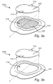
- Figs. 3a and 3b show medical dressings 300a, 300b according to at least two exemplary embodiments of the invention, in which a pad is completely removable from a central inspection area for enabling visual inspection of a treatment area.
- a pad is completely removable from a central inspection area for enabling visual inspection of a treatment area.
- Features being in common for the two dressings 300a, 300b are denoted with the same reference numerals in Figs. 3a and 3b .
- the central inspection area 312 of the illustrated medical dressing 300a is formed as a blind hole, the bottom (proximal end) of the hole being covered by a perforated film 332 extending across the central inspection area 312, similarly to the central inspection area 212 of the dressing 200 illustrated in Fig. 2 .
- the perforated film 332 is coated with an adhesive layer at the central inspection area, the perforation would also extend through the adhesive layer, which together with the film 332 would form a perforated body contact layer.
- the central inspection area 312 of Fig. 3a is defined by a raised wall portion 310 (which is similar to the raised wall 110 portion of Fig. 1 ).
- the embodiment illustrated in Fig. 3b has also a raised wall portion 310.
- the removable pad 302 is provided with two attachment means 314, for attaching the pad 302 to the wall portion 310 and keeping the pad 302 in its first state, i.e. the state in which the pad 302 and the medical dressing 300a, 300b is used for reducing the risk of pressure ulcers developing.
- One or both of the two attachment means 314 may be detached from the wall portion 310 to allow tilting or complete removal of the pad (i.e. arriving at its second state), whereby the central inspection area 312 may be visually inspected.
- the attachment means 314 may be arranged off-center compared to the axis or plane of symmetry X.
- the embodiment illustrated in Fig. 3b differs from the embodiment illustrated in Fig. 3a in that the central inspection area 312 is a through hole defined by the wall portion 310, i.e. it is void of any film or other material extending across the central inspection area 312.
- the embodiments illustrated in Figs. 3a and 3b may form part of a medical dressing system.
- a medical dressing system comprises the medical dressing 300a or 300b.
- the pad 302 may either be provided/packaged in a pre-assembled state, i.e. in said first state, or it may be provided/packaged as a separate component for subsequent placement in said first state.
- the pad 302 illustrated in Figs. 3a and 3b may be a first pad, wherein the system further comprises a replacement pad for replacing the first pad 302 while the medical dressing 300a, 300b is still applied to a human body without requiring removal of the border area from the skin of the body.
- a medical dressing may be configured and dimensioned to be applied to a knee, elbow, heel, etc, the latter being illustrated in Fig. 4 .
- Fig. 4 shows a medical dressing 400 according to at least one other exemplary embodiment of the invention.
- the medical dressing 400 is adapted to be placed on a heel of a human body.
- the medical dressing 400 does not only cover the heel but also extends across the foot sole, from which the adhesive border area 404 extends upwardly on both the medial and the lateral side of the foot.
- the pad 402 of the medical dressing 400 is herein illustrated as being located at least on the posterior side of the heel. Similarly to the other discussed embodiments, the pad 402 may be at least partly removed to uncover the central inspection area 412 for enabling visual inspection of the treatment area of the heel. It should be understood that the various structural features of the medical dressings in Figs.
- FIG. 1a-3 could be implemented in a medical dressing for any part of of the human body, such as for the heel as illustrated in Fig. 4 .
- Such structural features include, but are not limited to, the layers of the medical dressing, the attachment means, the presence or absence of a raised wall portion, the film of the border area extending across the central inspection area, etc.
Abstract
A medical dressing for application at a treatment area of a human body is provided. The dressing comprises a border area surrounding a central inspection area which is intended to be placed over said treatment area. The dressing also comprises a pad which may be arranged in the central inspection area and may be at least partly removed from the central inspection area for enabling visual inspection of the treatment area. There is also provided a medical dressing system and a method for reducing the workload for nursing personnel.
Description
- The present invention relates to a medical dressing for application at a treatment area of a human body. The invention also relates to a medical dressing system comprising such a medical dressing. Furthermore, the invention relates to a method of reducing workload for nursing personnel.
- Pressure ulcers very often arise among persons being bedridden for various reasons, such as for instance due to long term hospitalization or other causes of immobility. Not only does a pressure ulcer cause great discomfort and/or pain to the affected person, but it also causes difficulties to nursing personnel and other care-takers.
- It is therefore desirable in, for instance, hospitals to act proactively rather than reactively. In other words, instead of waiting for pressure ulcers to develop and then perform treatment, it is preferred to try to prevent the pressure ulcers from even occurring.
- Pressure ulcers are largely preventable. When pressure ulcers occur, they can become painful wounds that require months to heel. The prevention of pressure ulcers includes inspection of the skin, control of risk factors, keeping the skin clean and dry, and redistributing pressure over high risk bony areas.
- To date, such preventative means typically include pressure off-loading or re-positioning the patient at regular intervals such that pressure is relieved or re-distributed, and the amount of pressure that the individual is exposed to is minimized.
- Where a pressure sore has started to develop, or where it is expected to develop, nursing personnel may place a padded dressing onto the skin area. The nursing personnel needs to check from time to time to examine the skin underneath the dressing, and to see if a pressure ulcer has developed.
- The inspection of the skin area requires the dressing to be opened up, and detached from the skin. One option is, of course, to remove the dressing and apply a new dressing after having checked the relevant skin area. However, this is both costly and time consuming. Alternatively, nursing personnel may detach the dressing slighly by gripping and lifting an adhesive border of the dressing (i.e. the portion of the dressing surrounding the pad) so that the relevant skin area can be checked, and then the dressing is re-applied by re-attaching the adhesive border to the surrounding skin. Although this is cost effective and less time consuming than removing the old dressing and applying a new dressing, there are some drawbacks.
- One drawback is that the border loses some of its adhesive capability (stay-on ability) each time it is detached. An improperly adhered dressing also risks reducing the pressure ulcer prevention capability of the dressing. Furthermore there is a risk that the border will become wrinkled when detached and re-applied, which also reduces the adhesive capacity. Additionally, there is a riskt that such wrinkles turn into compartments for body fluids (such as sweat) which in turn may lead to such compartments growing as more fluid is accumulated, therefore further reducing the stay-on ability of the dressing. Eventually, the nursing personnel will, due to the resulting reduced stay-on ability, need to replace the old dressing with a new one.
- An object of the present invention is to aleviate the drawbacks of the prior art. This and other objects, which will become apparent in the following are accomplished by the accompanying claims.
- The present invention is based on the realization that by allowing at least a partial decoupling of a pad of a medical dressing from a surrounding border, the border does not have to be detached from the skin for inspection purposes and therefore the adhesive capability of the border is not impaired. In particular, the inventor has realized that the stay-on ability of a medical dressing can be retained by (instead of starting to lift the border) lifting or tilting the pad without needing to detach the border. This will result in longer stay-on ability of the medical dressing and less frequent need for replacing an old dressing with a new one. Furthermore, the handling of the dressing becomes easier for the nursing personnel when inspecting whether or not any pressure ulcers have developed. Thus, the present invention provides for beneficial technological and economical progress in the field of pressure ulcer prevention.
- According to at least a first aspect of the invention, there is provided a medical dressing for application at a treatment area of a human body. The medical dressing comprises
an annular border area comprising a film having - a body-facing proximal side provided with an adhesive layer for adhering the border area to skin surrounding said treatment area, and
- an opposite distal side,
a central inspection area for alignment with said treatment area, the central inspection area being surrounded by said border area, and
a pad movable between at least two states:- a first state in which the pad is located in the central inspection area, and
- a second state in which the pad is at least partly removed from the central inspection area for enabling visual inspection of said treatment area.
- It should be understood that in this application the term "treatment area" does not necessarily imply an injured, bruised, wounded or ulcerated area, but may on the contrary refer to an intact area of the human body onto which the medical dressing is placed for preventive purposes. Thus, the treatment performed by a caregiver may be a prophylactic treatment.
- The medical dressing is particularly useful for pressure ulcer prevention and/or pressure ulcer mitigation. The pad, which is suitably made of a material providing a pressure relieving function, can be at least partly lifted for allowing the treatment area to be visually (and as an option also tactilely) inspected. The lifting action may suitably be performed completely independent of the border area, which means that the border area may stay adhered to the skin surrounding the treatment area while the state of the pad is shifted.
- The border area is annular, which means that it forms a closed ringshaped path. Although the annular border may be circular or substantially circular, it should be noted that other annular shapes of the border are conceivable. For instance, the annular border area may form various types of curved paths or may even present non-curved straight side or sides. For instance, embodiments suitable for application onto the sacral area may have an annular border area forming a substantially heart-shaped path. Furthermore, in some embodiments, the annular border area may be provided with a notch or indentation at the outer perimeter of the border area, which in some cases may facilitate application of the dressing around certain skin areas, such as for instance at the gluteal cleft. Furthermore, in some embodiments, the annular border area may be provided with one or more tab portions projecting outwardly from the rest of the border area. In this connection it should be understood that inwardly means a direction towards the inner perimeter of the border area, i.e. a direction towards the pad, while outwardly is an opposite direction.
- In at least some exemplary embodiments, the border area defines a boundary of the central inspection area, while in other exemplary embodiments the central inspection area is defined by a raised wall portion which is surrounded by the border area. Allowing a border area to define the central inspection area may enable the production of a compact medical dressing. The production processes may include a first step in which a body contact layer (e.g. film coated with adhesive as described herein) which has been provided with a pre-cutout inspection hole is applied onto a backing layer. This will form the border area. Alternatively, the backing layer may be omitted and a thicker body contact layer may be used. In a second step a pad is applied to cover the inspection hole (which will thus form a central inspection area). The pad may suitably be provided with a narrow border portion. In an optional third step, one side of the pad is connected to the border area, e.g. by ultrasonic and/or heat welding or by use of a construction adhesive such as acrylic glue, thereby obtaining a hinged connection. It the pad is provided with a narrow border portion, that border portion may be connected to the border area of the medical dressing. In order to avoid unintentional lifting of the pad from the central inspection area, the pad may suitably be provided with attachment means, such as a tape which can be attached to the border area (or any other type of attachment means described in this specification).
- In some embodiments, the annular border area may be substantially heart-shaped and symmetrical about a geometrical axis of symmetry of the medical dressing. The axis of symmetry is located at a part of the dressing which will normally be applied in the gluteal cleft. The border area may comprise a first lobed portion on one side of said axis of symmetry and a second lobed portion on the other side of said axis of symmetry. The border area may be substantially heart shaped such that said first and second lobed portions form part of the lobed upper sides of a heart shape. The first and second lobed portions may be separated by a forked portion which replaces the pointed lower part of a heart shape. The forked portion of the border area may comprise a protrusion on either side of an interstice located coaxially with the axis of symmetry. Such a configuration is belived to improve the conformity to the sacral area of human body.
- In the field of medical dressings, in particular, wound dressings, a film provided with an adhesive layer for adhering to the patient is often referred to as a wound contact layer. The present invention is primarily intended for pressure ulcer prevention, i.e. for use on a human body area which has no wound. Therefore, in this application the combined film and adhesive layer will be referred to as a body contact layer. However, it should be understood that although the primary use of the invention is pressure ulcer prevention, if nursing personnel decides to use it as a wound dressing the body contact layer could be applied onto a wound.
- In this application directional terms such as "proximal" or "proximally" and "distal" or "distally" are used. These terms are referenced with respect to the intended placement on a treatment area of a human body. In other words, the most proximal portion of the medical dressing is the portion that is intended to be nearest treatment area. The most distal portion is the portion that is intended to be furthest away from the treatment area. For instance, the adhesive layer will be proximal to the film.
- The central inspection area may be embodied in different ways to enable visual inspection of the treatment area. In some example embodiments, the central inspection area comprises a through hole. In some example embodiments, the central inspection area comprises a blind hole. For instance a transparent film may be provided at the proximal end of the central inspection area. When the pad has been at least partly removed from the central inspection area, the transparent film may suitably be cleaned if it has become soiled by body exudates, thereby improving visual inspection. The dressing with the cleaned film may then be reused with the same pad or with a new pad. In some example embodiments, said transparent film may be in one piece with the film forming part of the border area. Thus, the medical dressing may be provided with a body contact layer which extends over the border area as well as the central inspection area. These various alternatives may be implemented for a medical dressing regardless if the central inspection area is defined by the border area or by a raised wall portion surrounded by the border area.
- Other advantages of having a film or body contact layer extending across the central inspection area include protection of the skin when the pad is lifted for inspection, improved stay-on ability of the medical dressing since substantially no pulling force is applied at an adhesive edge. The pad may be provided suitably be provided with an adhesive. With a film present in the central inspection area, a stronger adhesive may be provided on the proximal side of the pad than if the pad would be in direct contact with the skin, thus allowing for a good stay-on ability of the pad.
- A central inspection area in the form of a through hole, i.e. without a film extending across the central inspection area, may be desirable, for certain kinds of skin care regimes in which skin creams are used. Such a central inspection area will also facilitate palpating for the nursing personnel, for instance to detect raised skin temperature, which may be an indication of a developing ulcer.
- In at least some example embodiments the at least partly removable pad is attached to surrounding portion or portions of the medical dressing by means of separate attachment means. Such attachment means may, for instance, be a sticker or a hook and look type of fastening. As mentioned previously the surrounding portions may be the border area or a raised wall portion, either one being configurable for defining the central inspection area. In at least some exampl embodiments the at least partly removable pad is attached to surrounding portion or portions of the medical dressing by common material portions, e.g. acting as a hinge. However, in other embodiments the at least partly removable pad may be produced as a separate piece and may be subsequently connected by means of welding and/or gluing.
- The portion or portions surrounding the central inspection area may suitably comprise a raised portion of the medical dressing. This is reflected in at least one example embodiment, acccording to which said film lies in a first geometrical plane, the dressing further comprising a wall portion projecting distally from said first geometrical plane, wherein the wall portion at least partly defines said central inspection area. In at least some example embodiments the wall portion forms a frame around the central inspection area and around the pad. Similarly, the border area may be considered as forming a frame around the wall portion, the pad and the central inspection area. Thus, in at least some example embodiments, the pad, the wall portion and the border area may be arranged substantially coaxially.
- According to at least one example embodiment, one of the outer perimeter of the pad, the outer perimeter of the wall portion and the outer perimeter of the border area is substantially conformal with at least another one of the outer perimeter of the pad, the outer perimeter of the wall portion and the outer perimeter of the border area. According to at least one example embodiment all three outer perimeters are substantially conformal. According to at least one example embodiment, although the border area may be substantially conformal with the pad and/or the wall portion, the border area may be provided locally with small projecting tabs or indentations/notches.
- According to at least one example embodiment, said border area has an outer perimeter and an inner perimeter, wherein the inner perimeter borders to said wall portion. The distal end of the wall portion may lie in a second geometrical plane which is parallel to said first geometrical plane. Suitably, the border area is proximally spaced from the second geometrical plane. In other words, the thickness of the border area is suitably smaller than the thickness of said wall portion.
- According to at least one example embodiment, said pad is attached or attachable to said wall portion at least in said first state, i.e. the state in which the pad is located in the central inspection area. Thus, in at least some example embodiments, after the pad has been moved to the second state for enabling visual inspection of the treatment area, the pad may be re-attachable to said wall portion in order to again reach the first state. In other example embodiments, a new pad may be attached to the wall portion after a used pad has been moved to its second state. In some example embodiments, the pad stays attached to the wall portion when changing between the first state and the second state. The pad may, for instance, stay attached to the wall portion by means of a hinge element which may be a separate or an integrated part of the wall portion and the pad, or by means of other types of attachment means.
- According to at least one example embodiment, said pad is provided with releasable attachment means for attaching said pad to said wall portion, wherein releasing said attachment means enables the pad to be moved from said first state to said second state of the pad, wherein the attachment means allows re-attachment of said pad to said wall portion when said pad is moved back to said first state. Examples of such releasable attachment means are stickers, tapes or hook and loop type of fastening means.
- According to at least one example embodiment, a distal end surface of said wall portion and a distal end surface of said pad lie in a common second geometrical plane, said second geometrical plane being parallel with said first geometrical plane. Such a configuration may be beneficial for returning the pad to its first state and re-attaching the pad to the wall portion after visual inspection has been carried out. Furthermore, by providing a substantially even distal end surface of the medical dressing, undesired pressure points are avoided since the distal ends of the pad and wall portion lie in a common geometrical plane.
- According to at least one example embodiment, said pad is a cutout from said wall portion. Thus, the pad and the wall portion may be made from the same starting material or blank, from which the pad is cut out. Put differently, the pad and the wall portion may be obtainable from one common piece. For instance, the common piece may comprise an absorption layer and a backing layer distally to the absorption layer. The common piece from which the wall portion is made and the pad is cut out may also comprise other layers, such as a liquid distributing layer. It should therefore be understood that, in at least some example embodiments, the wall portion and the pad may be made in the same material or materials. Furthermore, it is not only the material that may be the same, but also the composition, density and/or layering, etc. may be the same in the pad as in the wall portion. Although, these example embodiments are advantageous from a manufacturing perspective, in at least some other example embodiments, the pad and the wall portion may be made from different pieces of material or from materials having different composition, density and/or layering. In other example embodiments, the pad could be manufactured separately and applied in a separate step to the rest of the wound dressing. The pad may be manufactured by ultrasonic cutting/welding, wherein layers of the pad are welded together forming a closed structure.
- Although the wall portion may advantageously be of the same material as the pad, in at least some embodiments, the wall portion may be of a different material. For instance, the wall portion may be of a foam material which is easy to shape and cut, and is conformable. The wall portion could be made of different gels (e.g. silicone, acrylic hydrogels or similar) which provide good pressure distribution.
- In at least some example embodiments the wall portion may be bevelled. The wall portion may suitably have its thicker portion nearest the central inspection area, and slanting to a thinner portion towards the surrounding border area. This may reduce the risk of peak pressures due to sharp edges and provide a good pressure gradient.
- As mentioned previously, the central inspection area may comprise a hole. It should therefore be understood that in embodiments having a wall portion defining said central inspection area, said wall portion may define a central hole included in said central inspection area. Similarly to the previous discussion, such a central hole may be a through hole or a blind hole. If it is a blind hole, the bottom of said blind hole may be formed by a film, such as the film which is also present at the border area. It should be understood that the wall portion may form a frame around the central hole, i.e. it may be annular.
- As mentioned previously, the body contact layer may extend over the central inspection area. In at least some example embodiments, a more general description is suitable, namely that said film at the border area extends into and across the central inspection area. Thus, this means that the film may be provided with an adhesive layer over substantially the entire extension of the film. However, this also means that in some other example embodiments, it is conceivable that only peripheral areas of the film are provided with the adhesive layer. For instance, only the film at the border area is provided with an adhesive layer, while the portion of the film interfacing proximally to the wall portion is void of adhesive layer. In some example embodiments only the portion of the film covering the hole of the inspection area is void of adhesive layer while the portion of the film at the border area and the portion of the film interfacing proximally to the wall portion are provided with the adhesive layer.
- According to at least one example embodiment, the body contact layer is perforated, wherein perforations extend from the distal to the proximal side of the body contact layer. Thus, in such cases the film provided with the adhesive layer is a perforated film, and the adhesive layer is a perforated adhesive layer. The perforations in the film may form a regular pattern. This allows any body exudates or other moisture to be transported away from the skin. However in other embodiments the film is not perforated. A non-perforated film may provide better adhesion to the skin, and avoids one process step during production.
- According to at least one example embodiment the film coated with the adhesive layer is a plastic film. Suitable materials for the plastic film include, but are not limited to, breathable polyolefin-based films (such as, e.g. polyethylene), polyamide, polyurethane, polyester and silicone. The film may have a thickness of from 15 to 100 µm, e.g. from 30 to 70 µm, e.g. from 45 to 60 µm. Suitably, the film is a thin polyurethane film.
- According to at least one example embodiment, the adhesive layer comprises a hydrophobic material. Examples of suitable adhesives include, but are not limited to, silicone gels, hot melt adhesives, acrylate adhesives, polyurethane gels, and hydrocolloid adhesives. In some embodiments, the adhesive is comprised of a material that is non-irritating to skin, for example, a silicone gel. Examples of suitable silicone gels include the two-component RTV systems such as Q72218 (Dow Corning) and SilGel 612 (Wacker Chemie AG) mentioned herein, as well as the NuSil silicone elastomers. In embodiments of the invention, the adhesive may comprise a silicone gel. For example, the adhesive may comprise a soft silicone gel having as softness (penetration) of from 8 to 22 mm, such as for example from 12 to 17 mm, as measured by a method based on ASTM D 937 and DIN 51580.
- According to at least one example embodiment, the medical dressing comprises a backing layer, which will generally be the most distal component of the wound dressing. The backing layer may typically be a thin film, sheet, or membrane that is vapour permeable and waterproof. Examples of suitable materials for the backing layer include, but are not limited to, polyurethane films, silicone films, polyester-based nonwoven materials, and laminates of polyester-based nonwoven materials and polyurethane films. The backing layer may be bonded to the pad, the wall portion and/or the body contact layer (i.e. the film coated with adhesive on the proximal side), for example, via an adhesive such as a pressure sensitive adhesive (such as an acrylic adhesive). In at least some embodiments, the backing layer is co-extensive with the body contact layer in that both layers have the same outer dimensions, and is bonded to the distal side of the film in the border area of the medical dressing.
- According to at least one example embodiment, the pad comprises a material that provides for good pressure distribution and fluid handling. For example, the pad may comprise an absorbent, conformable material such as, for example, foams and/or cellulose-based materials. The pad may comprise a hydrophilic material, e.g., a hydrophilic foam. Suitable foam materials include, but are not limited to polyurethane foams. In some embodiments, the pad comprises a porous foam.In some embodiments, the pad is a multilayered pad. For example, the pad may comprise two or more layers having different properties laminated together. For example, the pad may comprise a first absorbent layer on its proximal side and a second absorbent layer on its distal side, with the second absorbent layer being affixed to the backing layer. In some such embodiments, another layer is disposed between the first absorbent layer and the second absorbent layer, for example, a liquid distributing layer, which can act to spread liquid absorbed by the first absorbent layer and transmit the liquid to the second absorbent layer. In some embodiments, the first absorbent layer is comprised of a foam, for example, a hydrophilic foam such as a hydrophilic polyurethane foam. In some embodiments, the second absorbent layer comprises a superabsorbent material, such as superabsorbent fibers (SAF) or superabsorbent polymers (SAP). For example, polyacrylic super-absorbent fibers may be suitable. The second absorbent layer may also comprise binding fibers, non-limiting examples of which include polyester fibers, polyethylene fibers, polypropylene fibers, and blends thereof. Alternatively or additionally, the second absorbent layer may comprise cotton fibers. In some embodiments, the liquid distributing layer is thinner than both the first and second absorbent layers. In some embodiments, the liquid distributing layer is comprised of a nonwoven material, such as, for example, viscose, polyester, or both.
- When the medical dressing has been applied at the treatment area of the human body, it is desirable to have a good stay-on ability of the actual pad, so that it can provide its desired effect on to the treatment area (i.e. reduce the risk of a pressure ulcer developing). While one should strive for a good stay-on ability of the pad, the nursing staff should also be allowed to lift the pad and then place it back to its first state for a repeated number of times. Such a stay-on ability may be provided in different ways.
- In embodiments in which a film extends across the proximal end of the central inspection area, the pad is suitable provided with an adhesive for temporarily adhering the pad to the distal side of the film in the central inspeciton area. According to at least one example embodiment, the total adhesion energy between the pad and the film is lower than the total adhesion energy between the film and the skin. This is to avoid the medical dressing from loosening from the skin. However, it should be noted that the adhesion per area unit does not necessarily have to be higher between the film and the skin compared to the adhesion per area unit between the pad and the film, as long as the total adhesion energy is higher. The adhesion between the film and the skin may be provided by the herein discussed adhesive layer which together with the film forms the body contact layer.
- The adhesive strength between the pad and the film, as well as between the film and the skin may be 0.2- 4 N, suitably between 1-3 N, the adhesive strength being measured on 25 mm strips against steel using a 90 degree peel test (ASTM D3330//D3330M-04, method F, wherein the mean load was measured between 25 and 75 mm and the resting time after calendaring was 1 minute).
- The adhesive material for adhering the pad to the distal side of the film may be in the form of silicones, hot melts, acrylates, rubber-based, polyurethane-based.
- In embodiments in which the central inspection area is a through hole, i.e. without a film extending across the central inspection area, the pad may suitably be temporarily adhered to the naked skin by appropriate adhesive materials such as hydrogels, or any one of the above mentioned adhesive materials used for adhering to a film, as long as they are skin-friendly.
- Regardless of the pad being designed for temporary adhesion to a film or to the naked skin, the adhesive may be provided all over the proximal surface of the pad or in different patterns across the proximal surface of the pad.
- According to at least one example embodiment, the medical dressings comprises a release layer, intended to be removed before use. The release layer may be disposed on and releasably attached to the proximal side of the body contact layer. By "releasably attached," it is meant that the release layer may be peeled away from the rest of the medical dressing by hand. The release layer acts as a barrier that can protect the sterility of the pad and any adhesive present on the proximal surface of body contact layer (and any adhesive present on the backing layer and pad depending on their extension relatvie to the body contact layer) before the dressing is used. The release layer may be made of any of a variety of suitable materials known in the art, such as, for example, polyethylene, polyester, polypropylene, and silicone-coated paper.
- From the above, it should be understood that, the proximal side of the pad may be provided with adhesive. This may, for instance, be the case when said central inspection area defines a through hole, in which case the pad may be adhered to the treatment area. The adhesive may be any one of the above mentiond skin-friendly adhesive materials. A pad provided with an adhesive may also be conceivable in which the central inspection area defines a blind hole having its proximal end occluded by a film portion, in which case the pad may temporarily be adhered to the distal side of such a film portion.
- According to at least a second aspect of the invention, there is provided a medical dressing system. The medical dressing system comprises a medical dressing according to any embodiment of the first aspect of the invention, wherein said pad is provided in said first state or as a separate component for subsequent placement in said first state. Thus, the medical dressing system allows for the provision of a complete ready-to-use medical dressing in which the pad is already in the first state of the medical dressing, i.e. already located in the central inspection area. However, the medical dressing system also allows for the provision of a kit of components, in which the pad is one component and the rest of the medical dressing, including the border area and the central inspection area, is provided as another component to which the pad may be assembled. The pad may suitably be assembled to the rest of the medical dressing by any suitable attachment means, such as an attachment means of the type exemplified previously.
- According to at least one example embodiment of the medical dressing system, said pad is a first pad, the system further comprising a replacement pad for replacing the first pad while the medical dressing is still applied to a human body without requiring removal of the border area from the skin of the body. In other words, when the first pad has been used, e.g. soiled, it may be discarded and replaced by a fresh replacement pad. The border area may be left unaffected, thus not compromising the stay-on ability of the dressing. If the central inspection area comprises a blind hole having its proximal end covered by a film portion, the film portion may suitable be cleaned before the replacement pad is inserted into the blind hole.
- According to at least a third aspect of the invention, there is provided a method of reducing workload for nursing personnel. The method comprises providing a replacement pad for enabling the nursing personnel to replace a used pad comprised in a medical dressing according to any embodiment of the first aspect or a medical dressing system according to any embodiment of the second aspect with said replacement pad, without requiring removal of the border area from the skin of the body. This will facilitate for the nursing personnel to avoid replacing the entire medical dressing, since only the pad needs to be replaced. It is considered much easier to place a replacement pad to the central inspection area of an applied medical dressing, then applying an entire new dressing to a patient (not the least because of the challenge involved in applying the border area as wrinkle free as possible). Furthermore, even if eventually, the nursing personnel decides to change the entire medical dressing after a number of replacement pads have been used, such a change will be made much more seldom then with the prior art dressings, in which the border area needs to be lifted for visual inspection.
-
-
Fig. 1 shows a medical dressing according to at least one exemplary embodiment of the invention, the medical dressing having been applied at a treatment area of a human body. -
Fig. 1 a is a detailed view ofFig. 1 . -
Fig. 1b is a detailed view of the medical dressing inFigs. 1 and 1 a, illustrating an inspection of the treatment area. -
Fig. 2 shows a medical dressing according to at least one exemplary embodiment of the invention, in which a pad is partly removable from a central inspection area for enabling visual inspection of a treatment area. -
Fig. 2a shows a cross-section of a detail ofFig. 2 . -
Figs. 3a and 3b show medical dressings according to at least two exemplary embodiments of the invention, in which a pad is completely removable from a central inspection area for enabling visual inspection of a treatment area. -
Fig. 4 shows a medical dressing according to at least one other exemplary embodiment of the invention. -
Fig. 1 shows amedical dressing 100 according to at least one exemplary embodiment of the invention, themedical dressing 100 having been applied at a treatment area of a human body. In this figure, themedical dressing 100 has been applied to the gluteal cleft, however, the inventive concept can be readily implemented on other areas of the human body. -
Figs. 1 a and 1 b are detailed views illustrating the general prinicpal of the inventive concept. Themedical dressing 100 comprises apad 102 which covers an area of the human body where development of a pressure ulcer may occur. Thepad 102 is a preventive measure, which reduces the risk of pressure ulcers developing at the area covered by thepad 102. Thepad 102 is, therefore, suitably made of a pressure relieving material, such as materials exemplified previously in this specification. Thepad 102 is approproiately adapted to the gluteal cleft by being designed as a substantially heart-shaped pad. However, other shapes are also conceivable. In the illustrated embodiment, themedical dressing 100 is symmetrical on either side of a geometrical axis of symmetry X. - The
pad 102 is surrounded by anannular border area 104, i.e. aborder area 104 which forms a closed curve. Theborder area 104 comprises a firstlobed portion 106 on one side of said axis of symmetry X and a secondlobed portion 108 on the other side of said axis of symmetry X. Theborder area 104 may be substantially heart shaped such that said first and secondlobed portions border area 104 may be regarded as following the contours of a general heart shape, in other embodiments, as previously exemplified, the border area may have other shapes. - The
border area 104 comprises a film which has a body-facing proximal side provided with an adhesive layer for adhering the border area to the skin surrounding the treatment area. The opposite side of the film is referred to as the distal side. The distal side of the film may, in at least some embodiments, be attached to a backing layer. Such a backing layer may or may not cover also thepad 102. - In-between the
border area 104 and thepad 102, there is provided awall portion 110 of themedical dressing 100. Thewall portion 110 projects distally from the geometrical plane of the film. InFigs. 1a-1b thewall portion 110 forms a frame and defines a central inspection area 112 (seeFig. 1b ). It should, however, be noted that in other embodiments, thewall portion 110 does not necessarily form a complete closed curve (in the figure following a substantially heart-shaped contour), but could just partly define the central inspection area. In other embodiments, the wall portion may be completely omitted, wherein the border area may suitably define the central inspection window. Regardless of which one of a wall portion or a border area that forms the bounderies of the central insepction area in the various embodiments, it should be understood that in all embodiments, the border area will surround the central inspection area (either with or without an intermediate wall portion). - If a backing layer is attached to the film at the border area, such a backing layer may also cover and be attached to the wall portion.
- In
Fig. 1 a themedical dressing 100 is in a first state. In this first state thepad 102 is located in the central inspection area 112 (only visible inFig. 1 b) , thereby occluding visual inspection of the treatment area. Thus, it should be understood that thecentral inspection area 112 should be properly aligned with said treatment area.
Fig. 1b is a detailed view of themedical dressing 100 inFigs. 1 and 1 a, illustrating an inspection of the treatment area. The nursing staff has lifted thepad 102 into a second state, in which thepad 102 is at least partly removed from thecentral inspection area 112, thereby enabling visual inspection of the treatment area. Thepad 102 and thewall portion 110 may suitably be formed from the same piece of material and remain attached allong a point or line of attachment, even after lifting thepad 102 into the second state. - After inspection, the nursing staff may return the
pad 102 to its first state. Thepad 102 is suitably provided with an attachment means 114 (seeFig. 1 a) , such as a tab, a tongue, a sticker or any other suitable means of attachement. Such an attachment means 114 may be coated with adhesive. Rather than having an attachment means 114 on thepad 102, as in the figure, thewall portion 110 could instead or additionally be provided with an attachment means. Furthermore, instead of, or in addition to, an adhesive attachment means, there may be other solutions as well, such as hook-and-loop type of fastening, wherein hooks are present on one of saidpad 102 and saidwall portion 110 and loops for receiving the hooks are present on the other one of saidpad 102 and saidwall portion 110. -
Fig. 2 shows amedical dressing 200 according to at least one exemplary embodiment of the invention, in which apad 202 is partly removable from acentral inspection area 212 for enabling visual inspection of a treatment area. InFig. 2 , themedical dressing 200 lacks thewall portion 110 inFig. 1 . Instead, it is theborder area 204 that delimits thecentral inspection window 212. - The
medical dressing 200 inFig. 2 , is substantially heart-shaped and theborder area 204 comprises, similarly to the embodiment inFig. 1 , first and secondlobed portions Fig. 2 , the first and secondlobed portions portion 220 which replaces the pointed lower part of a heart shape. The forkedportion 220 of theborder area 204 comprises aprotrusion 222 on either side of aninterstice 224 located coaxially with the axis of symmetry. Thepad 202 inFig. 2 may, suitably, have a heart shape which substantially conforms with the heart shape of theborder area 204. Similarly, in the embodiment inFig. 1 , the shape of thewall portion 110 and/orpad 102 may substantially conform to the heart shape of theborder area 104, which may optionally be provided with a forked portion similarly to the one illustrated inFig. 2 . - As can be seen in the detailed cross-sectional view of
Fig. 2a , the border area comprises abody contact layer 230 which includes afilm 232 which on its proximal side is coated with anadhesive layer 234. Abacking layer 236 is attached to the distal side of thefilm 232. - Although the extension of the
film 232 may be limited to theborder area 204 in some embodiments, in at least some other embodiments (such as shown inFig. 2 ), thefilm 232 does not only form part of theborder area 204, but may suitably extend across the entiremedical dressing 200, thus also extending across thecentral inspection area 212. In such cases thebody contact layer 230 may be transparent. Thus, thefilm 232 may be made of a transparent material (and theadhesive layer 234 may also be transparent) so as to enable visual inspection of the treatment area when thepad 202 has been moved from its occlusive first state to its non-occlusive second state. The body contact layer 230 (i.e.film 232 combined with the adhesive layer 234) may suitably be provided withperforations 238 so as to allow moisture to be transported away from the skin. Suitably, thepad 202 may comprise an absorbent material (for instance, distributed in one or more layers of the pad) for absoring moisture that has travelled through theperforations 238. Before, during or after inspection, thefilm 232 may suitably be wiped off for improved visibility of the treatment area. - It should be understood that the embodiment of
Fig. 2 could be modified so that thefilm 232 does not extend across thecentral inspection area 212. Thecentral inspection area 212 could be a through hole. Furthermore, it shoud be understood that although the embodiment ofFig. 2 illustrates apad 202 which is only partly removable (thepad 202 remaining partly attached to themedical dressing 200 when lifted/tilted, e.g. remaining attached to a backing layer 236), themedical dressing 200 could be modified so that theentire pad 202 is removable. Examples of embodiments in which the entire pad is removable will be discussed in connection withFig. 3a and Fig. 3b . -
Figs. 3a and 3b showmedical dressings dressings Figs. 3a and 3b . - In
Fig. 3a thecentral inspection area 312 of the illustratedmedical dressing 300a is formed as a blind hole, the bottom (proximal end) of the hole being covered by aperforated film 332 extending across thecentral inspection area 312, similarly to thecentral inspection area 212 of the dressing 200 illustrated inFig. 2 . Thus, similarly toFig. 2 , if theperforated film 332 is coated with an adhesive layer at the central inspection area, the perforation would also extend through the adhesive layer, which together with thefilm 332 would form a perforated body contact layer. However, contrary to thecentral inspection area 212 ofFig. 2 , which is defined by the inner perimeter of theborder area 204, thecentral inspection area 312 ofFig. 3a is defined by a raised wall portion 310 (which is similar to the raisedwall 110 portion ofFig. 1 ). The embodiment illustrated inFig. 3b has also a raisedwall portion 310. - In each one of the embodiments illustrated in
Figs. 3a and 3b , theremovable pad 302 is provided with two attachment means 314, for attaching thepad 302 to thewall portion 310 and keeping thepad 302 in its first state, i.e. the state in which thepad 302 and themedical dressing wall portion 310 to allow tilting or complete removal of the pad (i.e. arriving at its second state), whereby thecentral inspection area 312 may be visually inspected. - In the illustrated embodiments in
Figs. 3a and 3b , when thepad 302 is properly placed in thecentral inspection area 312 in its first state, the geometrical axis of symmetry X or the plane of symmetry of thepad 302 will extend through the attachment means 314. However, in other embodiments the attachment means 314 may be arranged off-center compared to the axis or plane of symmetry X. - The embodiment illustrated in
Fig. 3b differs from the embodiment illustrated inFig. 3a in that thecentral inspection area 312 is a through hole defined by thewall portion 310, i.e. it is void of any film or other material extending across thecentral inspection area 312. - The embodiments illustrated in
Figs. 3a and 3b may form part of a medical dressing system. Such as system comprises themedical dressing pad 302 may either be provided/packaged in a pre-assembled state, i.e. in said first state, or it may be provided/packaged as a separate component for subsequent placement in said first state. Furthermore, thepad 302 illustrated inFigs. 3a and 3b may be a first pad, wherein the system further comprises a replacement pad for replacing thefirst pad 302 while themedical dressing - While the embodiments illustrated in
Figs. 1-3b are particularly suitable for being applied to the gluteal cleft, it should be understood that the general inventive concept could be realized for other parts of a human body. For instance, a medical dressing may be configured and dimensioned to be applied to a knee, elbow, heel, etc, the latter being illustrated inFig. 4 . -
Fig. 4 shows amedical dressing 400 according to at least one other exemplary embodiment of the invention. Themedical dressing 400 is adapted to be placed on a heel of a human body. For keeping themedical dressing 400 in place, themedical dressing 400 does not only cover the heel but also extends across the foot sole, from which theadhesive border area 404 extends upwardly on both the medial and the lateral side of the foot. Thepad 402 of themedical dressing 400 is herein illustrated as being located at least on the posterior side of the heel. Similarly to the other discussed embodiments, thepad 402 may be at least partly removed to uncover thecentral inspection area 412 for enabling visual inspection of the treatment area of the heel. It should be understood that the various structural features of the medical dressings inFigs. 1a-3 could be implemented in a medical dressing for any part of of the human body, such as for the heel as illustrated inFig. 4 . Such structural features include, but are not limited to, the layers of the medical dressing, the attachment means, the presence or absence of a raised wall portion, the film of the border area extending across the central inspection area, etc.
Claims (15)
- A medical dressing for application at a treatment area of a human body, comprising
an annular border area comprising a film having- a body-facing proximal side provided with an adhesive layer for adhering the border area to skin surrounding said treatment area, and- an opposite distal side,
a central inspection area for alignment with said treatment area, the central inspection area being surrounded by said border area, and
a pad movable between at least two states:- a first state in which the pad is located in the central inspection area, and- a second state in which the pad is at least partly removed from the central inspection area for enabling visual inspection of said treatment area. - The medical dressing as claimed in claim 1, wherein said border area defines a boundary of said central inspection area.
- The medical dressing as claimed in claim 1, wherein said film lies in a first geometrical plane, the dressing further comprising a wall portion projecting distally from said first geometrical plane, wherein the wall portion at least partly defines said central inspection area.
- The medical dressing as claimed in claim 3, wherein said pad is attached or attachable to said wall portion at least in said first state.
- The medical dressing as claimed in any one of claims 3-4, wherein said pad is provided with releasable attachment means for attaching said pad to said wall portion, wherein releasing said attachment means enables the pad to be moved from said first state to said second state of the pad, wherein the attachment means allows re-attachment of said pad to said wall portion when said pad is moved back to said first state.
- The medical dressing as claimed in any one of claims 3-5, wherein a distal end surface of said wall portion and a distal end surface of said pad lie in a common second geometrical plane, said second geometrical plane being parallel with said first geometrical plane.
- The medical dressing as claimed in any one of claims 3-6, wherein said pad is a cutout from said wall portion.
- The medical dressing as claimed in any one of claims 3-7, wherein said wall portion defines a central hole included in said central inspection area.
- The medical dressing as claimed in any one of claims 1-8, wherein said film extends into and across the central inspection area.
- The medical dressing as claimed in claim 9 when dependent on claim 8, wherein said central hole is a blind hole, the bottom of the blind hole being formed by said film.
- The medical dressing as claimed in any one of claims 1-10, wherein said film is perforated.
- The medical dressing as claimed in any one of claims 1-11, wherein the medical dressing is adapted for placement on a sacral area of a human body, wherein the medical dressing has a geometrical axis of symmetry, wherein the border area comprises a first lobed portion on one side of said axis of symmetry and a second lobed portion on the other side of said axis of symmetry.
- A medical dressing system comprising a medical dressing as claimed in any one of claims 1-12, wherein said pad is provided in said first state or as a separate component for subsequent placement in said first state.
- The medical dressing system as claimed in claim 12, wherein said pad is a first pad, the system further comprising a replacement pad for replacing the first pad while the medical dressing is still applied to a human body without requiring removal of the border area from the skin of the body.
- A method of reducing workload for nursing personnel, comprising providing a replacement pad for enabling the nursing personnel to replace a used pad comprised in a medical dressing as claimed in any one of claims 1-12 or in a medical dressing system as claimed in any one of claims 13-14 with said replacement pad, without requiring removal of the border area from the skin of the body.
Priority Applications (7)
| Application Number | Priority Date | Filing Date | Title |
|---|---|---|---|
| EP16176002.0A EP3260094A1 (en) | 2016-06-23 | 2016-06-23 | A medical dressing, a medical dressing system and a method of reducing workload for nursing personnel |
| ES17729156T ES2889023T3 (en) | 2016-06-23 | 2017-06-14 | A medical dressing, a medical dressing system and a method to reduce the workload of healthcare personnel |
| US16/312,227 US20190192351A1 (en) | 2016-06-23 | 2017-06-14 | A medical dressing, a medical dressing system and a method of reducing workload for nursing personnel |
| PCT/EP2017/064544 WO2017220404A1 (en) | 2016-06-23 | 2017-06-14 | A medical dressing, a medical dressing system and a method of reducing workload for nursing personnel |
| DK17729156.4T DK3474799T3 (en) | 2016-06-23 | 2017-06-14 | Medical dressing, medical dressing system and method of reducing the workload of nursing staff |
| EP17729156.4A EP3474799B1 (en) | 2016-06-23 | 2017-06-14 | A medical dressing, a medical dressing system and a method of reducing workload for nursing personnel |
| CN201780039027.3A CN109310529B (en) | 2016-06-23 | 2017-06-14 | Medical dressing, medical dressing system and method for reducing workload of medical staff |
Applications Claiming Priority (1)
| Application Number | Priority Date | Filing Date | Title |
|---|---|---|---|
| EP16176002.0A EP3260094A1 (en) | 2016-06-23 | 2016-06-23 | A medical dressing, a medical dressing system and a method of reducing workload for nursing personnel |
Publications (1)
| Publication Number | Publication Date |
|---|---|
| EP3260094A1 true EP3260094A1 (en) | 2017-12-27 |
Family
ID=56292478
Family Applications (2)
| Application Number | Title | Priority Date | Filing Date |
|---|---|---|---|
| EP16176002.0A Withdrawn EP3260094A1 (en) | 2016-06-23 | 2016-06-23 | A medical dressing, a medical dressing system and a method of reducing workload for nursing personnel |
| EP17729156.4A Active EP3474799B1 (en) | 2016-06-23 | 2017-06-14 | A medical dressing, a medical dressing system and a method of reducing workload for nursing personnel |
Family Applications After (1)
| Application Number | Title | Priority Date | Filing Date |
|---|---|---|---|
| EP17729156.4A Active EP3474799B1 (en) | 2016-06-23 | 2017-06-14 | A medical dressing, a medical dressing system and a method of reducing workload for nursing personnel |
Country Status (6)
| Country | Link |
|---|---|
| US (1) | US20190192351A1 (en) |
| EP (2) | EP3260094A1 (en) |
| CN (1) | CN109310529B (en) |
| DK (1) | DK3474799T3 (en) |
| ES (1) | ES2889023T3 (en) |
| WO (1) | WO2017220404A1 (en) |
Families Citing this family (5)
| Publication number | Priority date | Publication date | Assignee | Title |
|---|---|---|---|---|
| GB201115182D0 (en) | 2011-09-02 | 2011-10-19 | Trio Healthcare Ltd | Skin contact material |
| US20180214236A1 (en) * | 2017-01-25 | 2018-08-02 | Dawn Marie Leiva | Medical Consultation Stickers and Method of Use |
| KR102026319B1 (en) * | 2019-05-09 | 2019-09-27 | 이근철 | Modified member for dressing of wound |
| CN110256980B (en) * | 2019-06-20 | 2021-09-17 | 江苏省人民医院 | Antibacterial polyurethane flexible foam adhesive material for preventing pressure sores of infants and preparation method thereof |
| CN113616421A (en) * | 2021-09-09 | 2021-11-09 | 陈国军 | Application for preventing incontinent dermatitis |
Citations (4)
| Publication number | Priority date | Publication date | Assignee | Title |
|---|---|---|---|---|
| US4399816A (en) * | 1980-03-17 | 1983-08-23 | Spangler George M | Wound protector with transparent cover |
| US5562107A (en) * | 1995-09-27 | 1996-10-08 | Hollister Incorporated | Reclosable wound cover |
| WO2008149107A1 (en) * | 2007-06-06 | 2008-12-11 | Bristol-Myers Squibb Company | A wound dressing |
| WO2014060625A1 (en) * | 2012-10-17 | 2014-04-24 | Servicio Andaluz De Salud | Eye dressing |
Family Cites Families (14)
| Publication number | Priority date | Publication date | Assignee | Title |
|---|---|---|---|---|
| US4468227A (en) * | 1981-05-29 | 1984-08-28 | Hollister Incorporated | Wound drainage device with resealable access cap |
| US4917112A (en) * | 1988-08-22 | 1990-04-17 | Kalt Medical Corp. | Universal bandage with transparent dressing |
| US5056510A (en) * | 1989-04-13 | 1991-10-15 | The Kendall Company | Vented wound dressing |
| US5086763A (en) * | 1990-08-06 | 1992-02-11 | Hathman Johnnie L | Protective reclosable wound dressing |
| JPH07500266A (en) * | 1991-10-23 | 1995-01-12 | カミングス,ゲイリ、ウエイン | wound care system |
| GB9307624D0 (en) * | 1993-04-13 | 1993-06-02 | Smith & Nephew | Wound dressing |
| US5702356A (en) * | 1993-12-23 | 1997-12-30 | Hathman; Johnnie L. | Disposable wound dressing permitting non-invasive examination |
| US5704905A (en) * | 1995-10-10 | 1998-01-06 | Jensen; Ole R. | Wound dressing having film-backed hydrocolloid-containing adhesive layer with linear depressions |
| US7531711B2 (en) * | 2003-09-17 | 2009-05-12 | Ossur Hf | Wound dressing and method for manufacturing the same |
| US7135606B1 (en) * | 2004-07-15 | 2006-11-14 | Terrance Dozier | Wound dressing |
| US10413451B2 (en) * | 2009-01-06 | 2019-09-17 | Medline Industries, Inc. | Wound dressing |
| US7858838B2 (en) * | 2006-08-10 | 2010-12-28 | 3M Innovative Properties Company | Conformable wound dressing |
| US20120197206A1 (en) * | 2011-01-31 | 2012-08-02 | Glenn Bradley J | Adhesive dressing with resealable cover |
| JP7005518B2 (en) * | 2016-05-20 | 2022-01-21 | スリーエム イノベイティブ プロパティズ カンパニー | Replaceable dressing for visual inspection of tissue sites |
-
2016
- 2016-06-23 EP EP16176002.0A patent/EP3260094A1/en not_active Withdrawn
-
2017
- 2017-06-14 US US16/312,227 patent/US20190192351A1/en active Pending
- 2017-06-14 CN CN201780039027.3A patent/CN109310529B/en active Active
- 2017-06-14 DK DK17729156.4T patent/DK3474799T3/en active
- 2017-06-14 EP EP17729156.4A patent/EP3474799B1/en active Active
- 2017-06-14 ES ES17729156T patent/ES2889023T3/en active Active
- 2017-06-14 WO PCT/EP2017/064544 patent/WO2017220404A1/en unknown
Patent Citations (4)
| Publication number | Priority date | Publication date | Assignee | Title |
|---|---|---|---|---|
| US4399816A (en) * | 1980-03-17 | 1983-08-23 | Spangler George M | Wound protector with transparent cover |
| US5562107A (en) * | 1995-09-27 | 1996-10-08 | Hollister Incorporated | Reclosable wound cover |
| WO2008149107A1 (en) * | 2007-06-06 | 2008-12-11 | Bristol-Myers Squibb Company | A wound dressing |
| WO2014060625A1 (en) * | 2012-10-17 | 2014-04-24 | Servicio Andaluz De Salud | Eye dressing |
Also Published As
| Publication number | Publication date |
|---|---|
| EP3474799B1 (en) | 2021-07-21 |
| WO2017220404A1 (en) | 2017-12-28 |
| CN109310529A (en) | 2019-02-05 |
| ES2889023T3 (en) | 2022-01-11 |
| DK3474799T3 (en) | 2021-09-27 |
| US20190192351A1 (en) | 2019-06-27 |
| CN109310529B (en) | 2021-05-18 |
| EP3474799A1 (en) | 2019-05-01 |
Similar Documents
| Publication | Publication Date | Title |
|---|---|---|
| EP3474802B1 (en) | A medical dressing | |
| EP3474799B1 (en) | A medical dressing, a medical dressing system and a method of reducing workload for nursing personnel | |
| EP3474804B1 (en) | Medical dressing | |
| US5423737A (en) | Transparent hydrogel wound dressing with release tab | |
| WO2020028050A1 (en) | Tri-layered wound dressing and method therefor | |
| US20030199800A1 (en) | Bandage including perforated gel | |
| US20040220505A1 (en) | Dressing and a method for applying the same | |
| JPH06504694A (en) | Vascular catheter dressing with window | |
| US20210186765A1 (en) | Multifunctional release liner for dressings | |
| EP3474803B1 (en) | Medical dressing | |
| AU2018208515B2 (en) | Medical dressing for a convex body part | |
| US11197783B2 (en) | Two-part bandage with replaceable wound covering portion | |
| US20210038759A1 (en) | Low trauma wound dressings and adhesives for same | |
| WO2021011894A1 (en) | Adhesive bandages and methods for their use and manufacture |
Legal Events
| Date | Code | Title | Description |
|---|---|---|---|
| PUAI | Public reference made under article 153(3) epc to a published international application that has entered the european phase |
Free format text: ORIGINAL CODE: 0009012 |
|
| AK | Designated contracting states |
Kind code of ref document: A1 Designated state(s): AL AT BE BG CH CY CZ DE DK EE ES FI FR GB GR HR HU IE IS IT LI LT LU LV MC MK MT NL NO PL PT RO RS SE SI SK SM TR |
|
| AX | Request for extension of the european patent |
Extension state: BA ME |
|
| STAA | Information on the status of an ep patent application or granted ep patent |
Free format text: STATUS: THE APPLICATION IS DEEMED TO BE WITHDRAWN |
|
| 18D | Application deemed to be withdrawn |
Effective date: 20180628 |