EP3260079B1 - Screwdriver for dental implantology - Google Patents
Screwdriver for dental implantology Download PDFInfo
- Publication number
- EP3260079B1 EP3260079B1 EP17183481.5A EP17183481A EP3260079B1 EP 3260079 B1 EP3260079 B1 EP 3260079B1 EP 17183481 A EP17183481 A EP 17183481A EP 3260079 B1 EP3260079 B1 EP 3260079B1
- Authority
- EP
- European Patent Office
- Prior art keywords
- screwdriver
- screw
- varies
- base
- dynamic pillar
- Prior art date
- Legal status (The legal status is an assumption and is not a legal conclusion. Google has not performed a legal analysis and makes no representation as to the accuracy of the status listed.)
- Revoked
Links
- 239000007943 implant Substances 0.000 description 23
- 238000000034 method Methods 0.000 description 7
- 230000008878 coupling Effects 0.000 description 6
- 238000010168 coupling process Methods 0.000 description 6
- 238000005859 coupling reaction Methods 0.000 description 6
- 238000005266 casting Methods 0.000 description 5
- 230000000295 complement effect Effects 0.000 description 5
- 239000000463 material Substances 0.000 description 5
- 230000008569 process Effects 0.000 description 5
- 210000000988 bone and bone Anatomy 0.000 description 4
- 230000006872 improvement Effects 0.000 description 2
- 101710096655 Probable acetoacetate decarboxylase 1 Proteins 0.000 description 1
- 210000003484 anatomy Anatomy 0.000 description 1
- 238000000149 argon plasma sintering Methods 0.000 description 1
- 230000000712 assembly Effects 0.000 description 1
- 238000000429 assembly Methods 0.000 description 1
- 239000004053 dental implant Substances 0.000 description 1
- 238000005304 joining Methods 0.000 description 1
- 238000004519 manufacturing process Methods 0.000 description 1
- 238000003801 milling Methods 0.000 description 1
- 238000012986 modification Methods 0.000 description 1
- 230000004048 modification Effects 0.000 description 1
Images


Classifications
-
- A—HUMAN NECESSITIES
- A61—MEDICAL OR VETERINARY SCIENCE; HYGIENE
- A61C—DENTISTRY; APPARATUS OR METHODS FOR ORAL OR DENTAL HYGIENE
- A61C8/00—Means to be fixed to the jaw-bone for consolidating natural teeth or for fixing dental prostheses thereon; Dental implants; Implanting tools
- A61C8/0089—Implanting tools or instruments
-
- A—HUMAN NECESSITIES
- A61—MEDICAL OR VETERINARY SCIENCE; HYGIENE
- A61C—DENTISTRY; APPARATUS OR METHODS FOR ORAL OR DENTAL HYGIENE
- A61C1/00—Dental machines for boring or cutting ; General features of dental machines or apparatus, e.g. hand-piece design
- A61C1/08—Machine parts specially adapted for dentistry
- A61C1/082—Positioning or guiding, e.g. of drills
- A61C1/084—Positioning or guiding, e.g. of drills of implanting tools
-
- A—HUMAN NECESSITIES
- A61—MEDICAL OR VETERINARY SCIENCE; HYGIENE
- A61C—DENTISTRY; APPARATUS OR METHODS FOR ORAL OR DENTAL HYGIENE
- A61C8/00—Means to be fixed to the jaw-bone for consolidating natural teeth or for fixing dental prostheses thereon; Dental implants; Implanting tools
- A61C8/0018—Means to be fixed to the jaw-bone for consolidating natural teeth or for fixing dental prostheses thereon; Dental implants; Implanting tools characterised by the shape
- A61C8/0022—Self-screwing
-
- A—HUMAN NECESSITIES
- A61—MEDICAL OR VETERINARY SCIENCE; HYGIENE
- A61C—DENTISTRY; APPARATUS OR METHODS FOR ORAL OR DENTAL HYGIENE
- A61C8/00—Means to be fixed to the jaw-bone for consolidating natural teeth or for fixing dental prostheses thereon; Dental implants; Implanting tools
- A61C8/0048—Connecting the upper structure to the implant, e.g. bridging bars
- A61C8/005—Connecting devices for joining an upper structure with an implant member, e.g. spacers
- A61C8/0068—Connecting devices for joining an upper structure with an implant member, e.g. spacers with an additional screw
-
- A—HUMAN NECESSITIES
- A61—MEDICAL OR VETERINARY SCIENCE; HYGIENE
- A61C—DENTISTRY; APPARATUS OR METHODS FOR ORAL OR DENTAL HYGIENE
- A61C8/00—Means to be fixed to the jaw-bone for consolidating natural teeth or for fixing dental prostheses thereon; Dental implants; Implanting tools
- A61C8/0048—Connecting the upper structure to the implant, e.g. bridging bars
- A61C8/005—Connecting devices for joining an upper structure with an implant member, e.g. spacers
- A61C8/0074—Connecting devices for joining an upper structure with an implant member, e.g. spacers with external threads
-
- B—PERFORMING OPERATIONS; TRANSPORTING
- B25—HAND TOOLS; PORTABLE POWER-DRIVEN TOOLS; MANIPULATORS
- B25B—TOOLS OR BENCH DEVICES NOT OTHERWISE PROVIDED FOR, FOR FASTENING, CONNECTING, DISENGAGING OR HOLDING
- B25B15/00—Screwdrivers
- B25B15/001—Screwdrivers characterised by material or shape of the tool bit
- B25B15/004—Screwdrivers characterised by material or shape of the tool bit characterised by cross-section
- B25B15/005—Screwdrivers characterised by material or shape of the tool bit characterised by cross-section with cross- or star-shaped cross-section
-
- F—MECHANICAL ENGINEERING; LIGHTING; HEATING; WEAPONS; BLASTING
- F16—ENGINEERING ELEMENTS AND UNITS; GENERAL MEASURES FOR PRODUCING AND MAINTAINING EFFECTIVE FUNCTIONING OF MACHINES OR INSTALLATIONS; THERMAL INSULATION IN GENERAL
- F16B—DEVICES FOR FASTENING OR SECURING CONSTRUCTIONAL ELEMENTS OR MACHINE PARTS TOGETHER, e.g. NAILS, BOLTS, CIRCLIPS, CLAMPS, CLIPS OR WEDGES; JOINTS OR JOINTING
- F16B23/00—Specially shaped nuts or heads of bolts or screws for rotations by a tool
- F16B23/0007—Specially shaped nuts or heads of bolts or screws for rotations by a tool characterised by the shape of the recess or the protrusion engaging the tool
- F16B23/003—Specially shaped nuts or heads of bolts or screws for rotations by a tool characterised by the shape of the recess or the protrusion engaging the tool star-shaped or multi-lobular, e.g. Torx-type, twelve-point star
Definitions
- the present invention relates to a screwdriver for dental implantology, forming a fixing system and the components thereof to be used in a dynamic pillar assembly or in mechanized structures or structures sintered by CadCam laser.
- Said dynamic pillar assembly or mechanized structure are used in the production of prostheses on dental implants in human implantology in order to fix screws at an angle.
- the object of the present invention is to increase the screwing angle of the dynamic pillar or mechanized structure, providing advantages for improving the safety of the screwing system of the dynamic pillar or mechanized structure of the implant, correcting a large number of problems, increasing the durability, increasing the number of solutions for resolving aesthetic and functional problems, reducing the probability of the tool decoupling from the head of the screw during use thereof, increasing flexibility of use and maintaining the cost with respect to the screws and screwdrivers used in the prior art.
- the dynamic pillar which is the object of said invention, comprises two independent pieces constituting the base and the guide tube, or chimney, which are connected to each other by means of an articulation, of which independent pieces the base has a semi-spherical configuration and the chimney has, at the end of the coupling to the base, a complementary configuration, the articulation of which allows the chimney to form a maximum angle of 25° with the base, which is coupled by means of a screw to the longitudinal bore of the implant introduced into the bone, the pieces of which, base and chimney, following casting, form one single metallic piece having the desired angulation, which allows the correct positioning thereof, overcoming any incorrect angular arrangement of the implant in the bone, screwing said structure, at the corrected angulation, directly into the implant.
- the combination of said pieces, articulated base and chimney provide a freedom of movement of between 0° and 25° for positioning in relation one another at the desired angle prior to proceeding with the casting.
- Another object of said invention is the screwdriver (tool for coupling/decoupling by means of a screw of the dynamic pillar of said invention to the implant introduced into the bone), which has a protrusion in the form of a nut head which functions as a tip of the screw for coupling the dynamic pillar to the implant, by means of the complementary housing provided on the head of the screw and which has a substantially spherical configuration defined by a succession of faces constructed by surfaces in the form of interpolation of truncated spherical radii at both ends.
- the invention was developed to overcome the limitations and disadvantages of the guide tube or chimney, the screws and the screwdrivers of the prior art by means of constructive modifications which improve the safety of the screwing system of the dynamic pillar, allowing screwing at angles greater than 25 degrees and consequently correcting a greater number of angulation problems of the implants, increasing the number of solutions to problems of poor positioning in the area of the implants, increasing the durability of the screw and the screwdriver whilst displaying less wear due to a larger contact surface and better engagement and coupling between both and allowing greater flexibility of the male and female engagements, providing advantages such as the greater number of solutions for resolving aesthetic and functional problems, less probability of the screwdriver losing contact or decoupling from the screw during the threading, less probability of the geometric form of the head of the screw losing its form, greater flexibility of use and the same costs in relation to the screws and keys of the prior art.
- a first object of the present is a screwdriver according to claim 1.
- the hexalobular form has greater tangent radii in the exterior area than the known hexalobular systems, which allows the resistance and inclination of the screw and screwdriver assembly to be increased.
- the present invention is also applicable to metallic structures for implants produced by means of the CadCam process, not exclusively for dynamic pillar assemblies.
- the structures of the prosthesis produced by means of a casting process require the dynamic pillar as a base piece for modelling the structure in wax and then carrying out the casting, fixing the pillar in its correct position.
- the metallic structures formed by means of a CadCam process do not require the dynamic pillar since the structure is designed by computer and a tool machine mills said structure using only the screw and screwdriver of the system for the screwing thereof at angulation.
- the dynamic pillar assembly comprises two independent pieces which are the base (B) which is coupled to an implant and the guide tube or chimney (T) which is coupled to the base and via which an aesthetic material is inserted, these being connected to each other by means of an articulation with a semi-spherical configuration provided at the free end of the base (B) and a complementary configuration provided at the end of the coupling of the chimney with a cylindrical configuration, said guide tube (T) having a single access hole on the side opposite to that of the articulation with the base (B) which allows the introduction of a screw (P) and a screwdriver (C).
- the base (B) and the guide tube (T) which may be made of any material, metallic or plastic, form a single structure, having the form required for the buccal anatomy of the patient after having been anatomically modelled and subsequently cast, having the desired angulation in the interior of the structure to be situated in the correct position on the implant, although the latter is incorrectly inserted.
- Said single metallic structure is coupled by means of the base (B), already cast, by means of a retaining device, specifically a screw, which is threaded on the longitudinal thread of the implant which is in the bone, accessing the head of said screw by means of the hole existing in the chimney, said metallic structure being covered by an aesthetic material which simulates the tooth.
- the metallic structure may also be obtained by means of a CadCam process, in which the structure is designed by computer or subsequently manufactured directly by a tool machine or sintered by a laser.
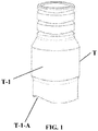
- a guide tube (T) of the dynamic pillar assembly comprises a body (T-1) in staggered cylindrical and conical form with improvements to the semi-circular body (T-1) at the lower edge of the side which allows a maximum inclination of 30°, preferably 28°, in the case of the dynamic pillar due to the design of the height of the semi-sphere of the dynamic pillar base, and up to 35°, preferably 30°, in the case of an angled channel obtained by a CadCam process, adjusting the design of the pitch of the screw in each case according to the length of the screw.
- the screw (P) of the dynamic pillar comprises a head (P-1) in cylindrical form followed by a body (P-2) in tapered form with its lower ends having a thread for the threading thereof with a conical seat and in semi-spherical form in the lower part.
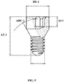
- the head (P-1) has an internal part (P-1-A) with female hexalobular form with a circular center and six depressions and six peaks alternating on the periphery, the head (P-1) having an external diameter (DE-1) which varies between 1.8 mm and 2.7 mm, greater internal diameter (DIMA-1) which varies between 1.3 and 2.4 mm, smaller internal diameter (DIME-1) which varies from 1.0 to 2.0 mm, an internal height of (AI-1) which varies from 0.5 to 1.5 mm, a radius of the depression (RDP-1) which varies from 0.15 to 0.35 mm, a radius of the peak (RCP) which varies from 0.15 to 0.35 mm, an angle of the cone (ADC-1) which varies from 25 to 65 degrees and a total height (AT-1) which varies from 2 to 15 mm.
- DE-1 external diameter
- DIMA-1 greater internal diameter
- DIME-1 smaller internal diameter
- AI-1 internal height of
- AI-1 which
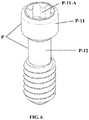
- an alternative screw (P) of the dynamic pillar of the present industrial design is shown which may comprise a head (P-11) in cylindrical form, with an upright seat and a body (P-12) in cylindrical form with a lower end with a cylindrical body of smaller diameter than the head and followed by a thread of greater external diameter than the cylindrical body finished in a semi-spherical form in the lower part.
- the head (P-11) has an internal part (P-11-A) with a hexalobular form with a circular center and six depressions and six peaks alternating on the periphery, the head (P-11) having an external diameter (DE-11) which varies from 1.8 mm to 2.7 mm in diameter, a greater internal diameter (DIMA-11) which varies from 1.3 to 2.4 mm, a greater internal diameter (DIME-11) which varies from 1.0 to 2.0 mm, an internal height (AI-11) which varies from 0.5 to 1.5 mm, a radius of the depression (RDP-11) which varies from 0.15 to 0.35 mm, a radius of the peak (RCP-11) which varies from 0.15 to 0.35 mm and a total height (AT-11) which varies from 2 to 15 mm.
- DE-11 external diameter
- DIMA-11 greater internal diameter
- DIME-11 greater internal diameter
- AI-11 internal height
- AI-11 internal height
- RDP-11 radius of the depression
- RDP-11 radius of the
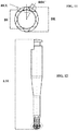
- the screwdriver (C) of the dynamic pillar comprises a body (C-1) in cylindrical and tapered form with an upper part preferably in a "T" form with a curved upper face and a cut face with a cut extended into the upper cylinder, intermediate part in tapered form and lower part with grooves and curves with improvement to the tip (C-2) in semi-spherical form with curved holes (C-2-A) and protrusions (C-2-B) forming a male hexalobular type screwdriver, with an external diameter (DE) which varies from 1.3 to 2.4 mm, an internal diameter (DI) which varies from 1.0 to 2.0 mm, the radius of the depression (RCD) which varies from 0.15 to 0.35 mm, the radius of the peak (RCC) which varies from 0.15 to 0.35 mm and a total height (ATC) which varies from 18 to 35 mm.
- DE external diameter
- DI internal diameter
- DI internal diameter
- RCD radius of the depression
- the adjustment between the screw and the screwdriver is carried out by means of tangent radii adapted between said screw and screwdriver, which allows torque at an inclination of up to 35°, preferably 30° to be applied.
- the procedure for correcting the incorrectly positioned implants by means of the dynamic pillar and the elements of the present invention comprises the following steps:
- the procedure for correcting incorrectly positioned implants by means of CadCam and the elements of the present invention comprises the following steps:
Description
- The present invention relates to a screwdriver for dental implantology, forming a fixing system and the components thereof to be used in a dynamic pillar assembly or in mechanized structures or structures sintered by CadCam laser. Said dynamic pillar assembly or mechanized structure are used in the production of prostheses on dental implants in human implantology in order to fix screws at an angle.
- The object of the present invention is to increase the screwing angle of the dynamic pillar or mechanized structure, providing advantages for improving the safety of the screwing system of the dynamic pillar or mechanized structure of the implant, correcting a large number of problems, increasing the durability, increasing the number of solutions for resolving aesthetic and functional problems, reducing the probability of the tool decoupling from the head of the screw during use thereof, increasing flexibility of use and maintaining the cost with respect to the screws and screwdrivers used in the prior art.
- In the international patent application,
WO2006/0247680 - According to the cited invention, the combination of said pieces, articulated base and chimney, provide a freedom of movement of between 0° and 25° for positioning in relation one another at the desired angle prior to proceeding with the casting. Another object of said invention is the screwdriver (tool for coupling/decoupling by means of a screw of the dynamic pillar of said invention to the implant introduced into the bone), which has a protrusion in the form of a nut head which functions as a tip of the screw for coupling the dynamic pillar to the implant, by means of the complementary housing provided on the head of the screw and which has a substantially spherical configuration defined by a succession of faces constructed by surfaces in the form of interpolation of truncated spherical radii at both ends.
- Although the guide tube or chimney has fulfilled the requirement of orientating the screwdriver together with the screw, their characteristics limit the tightening process of said screw at a maximum angle of 25°, producing disadvantages in serving a limited number of applications and solutions to problems, with high probability that the thread will be lost, with low probability of solving aesthetic and functional problems and less flexibility of use.
- The screws and the screwdriver of said invention have the following problems, which the present invention solves:
- a) Limited angle up to a maximum of 25 degrees;
- b) As the spherical tip of the screwdriver has a hexagonal form and the female part of the head of the screw also has the same form, the tightening only occurs by means of the perfect engagement of both;
- c) The probability of the screwdriver decoupling from the head of the screw is very high;
- d) Reduces the probability of the hexagon of the head of the screw losing its hexagonal form, a very high probability in the currently known systems, which causes the tip of the screwdriver to rotate in its interior, impeding the correct functioning of the assembly during the tightening thereof.
- At the same time, in the prior art there exist different fixing devices for the joining of the two elements, in particular, screws which have heads with different geometries which work with tips of complementary screws for the screwing of the screw to another element by means of a thread. In the prior art, no fixing device with a head at one end and a thread at the opposite end is known which allows the actuation thereof by means of a screwdriver in such a way that between the axis of the tip of the screwdriver and the head of the screw where the tip of the screwdriver is introduced there exists a degree greater than 25° and allows the tightening with sufficient guarantees.
- The invention was developed to overcome the limitations and disadvantages of the guide tube or chimney, the screws and the screwdrivers of the prior art by means of constructive modifications which improve the safety of the screwing system of the dynamic pillar, allowing screwing at angles greater than 25 degrees and consequently correcting a greater number of angulation problems of the implants, increasing the number of solutions to problems of poor positioning in the area of the implants, increasing the durability of the screw and the screwdriver whilst displaying less wear due to a larger contact surface and better engagement and coupling between both and allowing greater flexibility of the male and female engagements, providing advantages such as the greater number of solutions for resolving aesthetic and functional problems, less probability of the screwdriver losing contact or decoupling from the screw during the threading, less probability of the geometric form of the head of the screw losing its form, greater flexibility of use and the same costs in relation to the screws and keys of the prior art.
- Therefore, a first object of the present is a screwdriver according to
claim 1. The hexalobular form has greater tangent radii in the exterior area than the known hexalobular systems, which allows the resistance and inclination of the screw and screwdriver assembly to be increased. - The present invention is also applicable to metallic structures for implants produced by means of the CadCam process, not exclusively for dynamic pillar assemblies. The structures of the prosthesis produced by means of a casting process require the dynamic pillar as a base piece for modelling the structure in wax and then carrying out the casting, fixing the pillar in its correct position. On the other hand, the metallic structures formed by means of a CadCam process do not require the dynamic pillar since the structure is designed by computer and a tool machine mills said structure using only the screw and screwdriver of the system for the screwing thereof at angulation.
- To complement the description and with the aim to provide a better understanding of the characteristics of the invention, a set of figures is included, in which the following is depicted in an illustrative and non-limiting character:
-
Figure 1 shows a frontal perspective view of a guide tube of the dynamic pillar; -
Figure 2 shows the frontal perspective view of a screw of the dynamic pillar; -
Figure 3 shows the upper view of the screw of the dynamic pillar; -
Figure 4 shows the upper view with greater detail of the depressions and peaks of the screw of the dynamic pillar; -
Figure 5 shows the frontal and sectional rear view of the screw of the dynamic pillar; -
Figure 6 shows the frontal perspective view of an alternative of the screw of the dynamic pillar; -
Figure 7 shows the upper view of the screw of the previous figure; -
Figure 8 shows the upper view with greater detail of the depressions and peaks of the screw of the previous figure; -
Figure 9 shows the frontal and sectional rear view of the screw of the previous figure; -
Figure 10 shows the perspective view of a screwdriver of the dynamic pillar; -
Figure 11 shows the upper view of the screwdriver; -
Figure 12 shows a lateral view of the screwdriver; and -
Figure 13 shows a section of the assembly, base, chimney and screw of the pillar. -
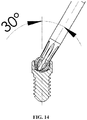
Figure 14 shows a section of the screw with the tip of the screwdriver introduced into the head of the screw. - The dynamic pillar assembly comprises two independent pieces which are the base (B) which is coupled to an implant and the guide tube or chimney (T) which is coupled to the base and via which an aesthetic material is inserted, these being connected to each other by means of an articulation with a semi-spherical configuration provided at the free end of the base (B) and a complementary configuration provided at the end of the coupling of the chimney with a cylindrical configuration, said guide tube (T) having a single access hole on the side opposite to that of the articulation with the base (B) which allows the introduction of a screw (P) and a screwdriver (C).
- The base (B) and the guide tube (T) which may be made of any material, metallic or plastic, form a single structure, having the form required for the buccal anatomy of the patient after having been anatomically modelled and subsequently cast, having the desired angulation in the interior of the structure to be situated in the correct position on the implant, although the latter is incorrectly inserted. Said single metallic structure is coupled by means of the base (B), already cast, by means of a retaining device, specifically a screw, which is threaded on the longitudinal thread of the implant which is in the bone, accessing the head of said screw by means of the hole existing in the chimney, said metallic structure being covered by an aesthetic material which simulates the tooth. The metallic structure may also be obtained by means of a CadCam process, in which the structure is designed by computer or subsequently manufactured directly by a tool machine or sintered by a laser.
- In accordance with
Figure 1 , a guide tube (T) of the dynamic pillar assembly comprises a body (T-1) in staggered cylindrical and conical form with improvements to the semi-circular body (T-1) at the lower edge of the side which allows a maximum inclination of 30°, preferably 28°, in the case of the dynamic pillar due to the design of the height of the semi-sphere of the dynamic pillar base, and up to 35°, preferably 30°, in the case of an angled channel obtained by a CadCam process, adjusting the design of the pitch of the screw in each case according to the length of the screw. - In accordance with
Figures 2 to 5 , the screw (P) of the dynamic pillar comprises a head (P-1) in cylindrical form followed by a body (P-2) in tapered form with its lower ends having a thread for the threading thereof with a conical seat and in semi-spherical form in the lower part. The head (P-1) has an internal part (P-1-A) with female hexalobular form with a circular center and six depressions and six peaks alternating on the periphery, the head (P-1) having an external diameter (DE-1) which varies between 1.8 mm and 2.7 mm, greater internal diameter (DIMA-1) which varies between 1.3 and 2.4 mm, smaller internal diameter (DIME-1) which varies from 1.0 to 2.0 mm, an internal height of (AI-1) which varies from 0.5 to 1.5 mm, a radius of the depression (RDP-1) which varies from 0.15 to 0.35 mm, a radius of the peak (RCP) which varies from 0.15 to 0.35 mm, an angle of the cone (ADC-1) which varies from 25 to 65 degrees and a total height (AT-1) which varies from 2 to 15 mm. - In accordance with
Figures 6 to 9 , an alternative screw (P) of the dynamic pillar of the present industrial design is shown which may comprise a head (P-11) in cylindrical form, with an upright seat and a body (P-12) in cylindrical form with a lower end with a cylindrical body of smaller diameter than the head and followed by a thread of greater external diameter than the cylindrical body finished in a semi-spherical form in the lower part. The head (P-11) has an internal part (P-11-A) with a hexalobular form with a circular center and six depressions and six peaks alternating on the periphery, the head (P-11) having an external diameter (DE-11) which varies from 1.8 mm to 2.7 mm in diameter, a greater internal diameter (DIMA-11) which varies from 1.3 to 2.4 mm, a greater internal diameter (DIME-11) which varies from 1.0 to 2.0 mm, an internal height (AI-11) which varies from 0.5 to 1.5 mm, a radius of the depression (RDP-11) which varies from 0.15 to 0.35 mm, a radius of the peak (RCP-11) which varies from 0.15 to 0.35 mm and a total height (AT-11) which varies from 2 to 15 mm. - Due to an exclusive hexalobular geometric design, with exterior radii with greater resistant section and adapted to the adjustment between the screw and the screwdriver, an inclination of up to 35 effective degrees, preferably 30°, is allowed for applying the tightening torque and loosening of the screw.
- In accordance with
Figures 10 to 12 , the screwdriver (C) of the dynamic pillar comprises a body (C-1) in cylindrical and tapered form with an upper part preferably in a "T" form with a curved upper face and a cut face with a cut extended into the upper cylinder, intermediate part in tapered form and lower part with grooves and curves with improvement to the tip (C-2) in semi-spherical form with curved holes (C-2-A) and protrusions (C-2-B) forming a male hexalobular type screwdriver, with an external diameter (DE) which varies from 1.3 to 2.4 mm, an internal diameter (DI) which varies from 1.0 to 2.0 mm, the radius of the depression (RCD) which varies from 0.15 to 0.35 mm, the radius of the peak (RCC) which varies from 0.15 to 0.35 mm and a total height (ATC) which varies from 18 to 35 mm. - The adjustment between the screw and the screwdriver is carried out by means of tangent radii adapted between said screw and screwdriver, which allows torque at an inclination of up to 35°, preferably 30° to be applied.
- By means of the previous elements, and in particular by means of coupling and connection of the screw and the screwdriver, it is possible to achieve an articulation which allows the guide tube or chimney (T) to form an angle from 0° to 35°, preferably 30°, in relation to the base (B), as is observed in
Figures 13 and14 . - At the same time, the procedure for correcting the incorrectly positioned implants by means of the dynamic pillar and the elements of the present invention, comprises the following steps:
- Obtaining an impression of the mouth of the patient who has the implant;
- Obtaining a working model of the mouth of the patient with the exact position of the implants which the patient has;
- Screwing, using the screw (P) and the screwdriver, (C) a dynamic pillar, with its base (B) and guide tube (T), into a replica of the implant in the working model and positioning the guide tube (T) at a desired angulation in relation to the base (B);
- Fixing the position between the base (B) and the guide tube (T) at a previously defined angulation;
- Anatomical modelling of the form of the client on the base (B) and the guide tube (T);
- Unscrewing, using the screw (P) and the screwdriver (C), the modelled assembly formed by the base (B) and guide tube (T) from the replica of the implant;
- Casting the modelled assembly of the base (B) and guide tube (T) for obtaining a single metallic structure;
- Screwing, using the screw (P) and the screwdriver (C), the metallic structure into the implant of the mouth of the patient;
- Covering said metallic structure with aesthetic material, which simulates the tooth.
- At the same time, the procedure for correcting incorrectly positioned implants by means of CadCam and the elements of the present invention comprises the following steps:
- Obtaining an impression of the mouth of the patient who has the implant;
- Obtaining a working model of the mouth of the patient with the exact position of the implants which the patient has;
- Scanning the model in order to reproduce it in 3D;
- Modelling the future metallic structure using the CAD software;
- Sending the design of the structure to a tool machine which mills the structure using the commands from the CAM software;
- Screwing, using the screw (P) and the screwdriver (C), the metallic structure into the implant of the mouth of the patient; and
- Covering said metallic structure with aesthetic material, which simulates the tooth.
- As mentioned previously, instead of using a milling machine, it is possible to use a laser sintering machine, which executes the commands from the CAM software.
Claims (2)
- Screwdriver, for a dynamic pillar for dental implantology, the screwdriver comprising a tip (C-2) in semi-spherical form with curved inlets and protrusions (C-2-B) forming a male hexalobular type screwdriver, the screwdriver being characterized in that the hexalobular tip (C-2) is in accordance with ISO 10664 with,a. an external diameter (DE) which varies from 1.3 to 2.4 mm,b. an internal diameter (DI) which varies from 1.0 to 2.0 mm,c. a radius of the depression (RCD) which varies from 0.15 to 0.35 mm, andd. a radius of the peak (RCC) which varies from 0.15 to 0.35 mm.such that the hexalobular tip (C-2) situated in the exterior area allows an inclination of between 0° and 35° for the application of a tightening torque on a screw.
- Screwdriver, according to claim 1, characterized in that it has a total height (ATC) which varies from 18 to 35 mm.
Priority Applications (1)
| Application Number | Priority Date | Filing Date | Title |
|---|---|---|---|
| PL17183481T PL3260079T3 (en) | 2012-11-19 | 2013-03-27 | Screwdriver for dental implantology |
Applications Claiming Priority (3)
| Application Number | Priority Date | Filing Date | Title |
|---|---|---|---|
| BRBR102012029369-2A BR102012029369A2 (en) | 2012-11-19 | 2012-11-19 | IMPROVEMENTS INTRODUCED IN DYNAMIC PILLAR ASSEMBLY |
| PCT/ES2013/070210 WO2014076332A1 (en) | 2012-11-19 | 2013-03-27 | Screw, tool and assembly for dental implantology |
| EP13854954.8A EP2932937B1 (en) | 2012-11-19 | 2013-03-27 | Screw and assembly for dental implantology |
Related Parent Applications (2)
| Application Number | Title | Priority Date | Filing Date |
|---|---|---|---|
| EP13854954.8A Division EP2932937B1 (en) | 2012-11-19 | 2013-03-27 | Screw and assembly for dental implantology |
| EP13854954.8A Division-Into EP2932937B1 (en) | 2012-11-19 | 2013-03-27 | Screw and assembly for dental implantology |
Publications (2)
| Publication Number | Publication Date |
|---|---|
| EP3260079A1 EP3260079A1 (en) | 2017-12-27 |
| EP3260079B1 true EP3260079B1 (en) | 2018-07-25 |
Family
ID=50730625
Family Applications (5)
| Application Number | Title | Priority Date | Filing Date |
|---|---|---|---|
| EP17207308.2A Ceased EP3335668A1 (en) | 2012-11-19 | 2013-03-27 | Screw, assembly and procedure for dental implantology |
| EP13854954.8A Revoked EP2932937B1 (en) | 2012-11-19 | 2013-03-27 | Screw and assembly for dental implantology |
| EP17183481.5A Revoked EP3260079B1 (en) | 2012-11-19 | 2013-03-27 | Screwdriver for dental implantology |
| EP22159051.6A Pending EP4026514A1 (en) | 2012-11-19 | 2013-03-27 | Screw, assembly and procedure for dental implantology |
| EP20165703.8A Pending EP3735935A1 (en) | 2012-11-19 | 2013-03-27 | Screw, assembly and system for dental implantology |
Family Applications Before (2)
| Application Number | Title | Priority Date | Filing Date |
|---|---|---|---|
| EP17207308.2A Ceased EP3335668A1 (en) | 2012-11-19 | 2013-03-27 | Screw, assembly and procedure for dental implantology |
| EP13854954.8A Revoked EP2932937B1 (en) | 2012-11-19 | 2013-03-27 | Screw and assembly for dental implantology |
Family Applications After (2)
| Application Number | Title | Priority Date | Filing Date |
|---|---|---|---|
| EP22159051.6A Pending EP4026514A1 (en) | 2012-11-19 | 2013-03-27 | Screw, assembly and procedure for dental implantology |
| EP20165703.8A Pending EP3735935A1 (en) | 2012-11-19 | 2013-03-27 | Screw, assembly and system for dental implantology |
Country Status (10)
| Country | Link |
|---|---|
| US (2) | US10470852B2 (en) |
| EP (5) | EP3335668A1 (en) |
| BR (1) | BR102012029369A2 (en) |
| DK (2) | DK2932937T3 (en) |
| ES (2) | ES2665548T3 (en) |
| HU (2) | HUE036865T2 (en) |
| NO (1) | NO2932937T3 (en) |
| PL (2) | PL2932937T3 (en) |
| PT (2) | PT3260079T (en) |
| WO (1) | WO2014076332A1 (en) |
Families Citing this family (10)
| Publication number | Priority date | Publication date | Assignee | Title |
|---|---|---|---|---|
| WO2017070335A1 (en) * | 2015-10-20 | 2017-04-27 | Implant Direct Sybron International Llc | Screw and driver tool for dental procedures |
| ES2635650B2 (en) * | 2016-04-04 | 2019-05-23 | Vogul S L U | Screw and driving tool for dental implantology. |
| USD817164S1 (en) * | 2016-08-19 | 2018-05-08 | Katsuyuki Totsu | Screw |
| EP3309413A1 (en) * | 2016-10-17 | 2018-04-18 | Bossard AG | Attachment element |
| TWI599455B (en) * | 2016-11-23 | 2017-09-21 | Driven tool that tilts the workpiece | |
| USD892604S1 (en) * | 2018-11-08 | 2020-08-11 | Superior Tool Co., Ltd. | Screw |
| USD888544S1 (en) * | 2019-01-28 | 2020-06-30 | National Nail Corp. | Fastener head |
| US11821453B2 (en) | 2019-04-18 | 2023-11-21 | Sheh Fung Screws Co., Ltd. | Fastener having improved wobble control, fastening system including the same, and method of forming the same |
| DE102020003492A1 (en) | 2020-06-11 | 2021-12-16 | Bruno Spindler | Twisting instrument |
| EP4260982A1 (en) | 2022-04-11 | 2023-10-18 | Bonastre Biomed, SL | Screw, screwdriver and screw fastening set |
Citations (8)
| Publication number | Priority date | Publication date | Assignee | Title |
|---|---|---|---|---|
| US5251521A (en) | 1992-01-31 | 1993-10-12 | Bondhus Corporation | TORX-compatible elliptical driver |
| DE20108605U1 (en) | 2001-05-22 | 2001-11-22 | Waller Peter | Screwdriver, bit and screw head |
| WO2006012273A1 (en) | 2004-06-29 | 2006-02-02 | Lifecore Biomedical, Inc. | Internal connection dental implant |
| EP1810641A1 (en) | 2004-07-30 | 2007-07-25 | Esteban Xam-Mar Mangrane | Dynamic pier for correcting incorrectly-positioned implants and corresponding tool |
| ES2279676A1 (en) | 2005-03-23 | 2007-08-16 | Esteban Xam-Mar Mangrane | Dynamic pier for correcting implants in bone, has base and shaft so that the base has hemispherical configuration and end of shaft coupled to base has complementary configuration |
| US20080132958A1 (en) | 2006-11-30 | 2008-06-05 | Normed Medizin-Technik Vertriebs Gmbh | Orthopedic compression screw |
| EP2420354A1 (en) | 2009-04-16 | 2012-02-22 | Universal Ball Head, S.L. | Structure for coupling between a screw head and a tightening tool |
| EP2607722A1 (en) | 2011-12-22 | 2013-06-26 | Straumann Holding AG | Connecting screw for a dental implant |
Family Cites Families (19)
| Publication number | Priority date | Publication date | Assignee | Title |
|---|---|---|---|---|
| US2083092A (en) * | 1936-01-20 | 1937-06-08 | Joseph R Richer | Screw |
| CH696549A5 (en) * | 2003-06-06 | 2007-07-31 | Medartis Ag | Screw and tool or loosening the screw. |
| FR2874174B1 (en) | 2004-08-11 | 2006-11-24 | Bourjois Soc Par Actions Simpl | COSMETIC COMPOSITION COMPRISING A SUPERABSORBENT POLYMER |
| US7513905B2 (en) * | 2004-11-03 | 2009-04-07 | Jackson Roger P | Polyaxial bone screw |
| US20090151519A1 (en) * | 2007-12-14 | 2009-06-18 | Monyem Sylvanus I | Dual socket for fast pace assembly environment |
| ES2336062B1 (en) * | 2008-04-24 | 2011-03-28 | Ramon Farre Berga | SCREW TO SET A PROTESIS ON A DENTAL IMPLANT, CARRIER, KIT AND TIGHTENING WRENCH. |
| GB0823043D0 (en) | 2008-12-18 | 2009-01-28 | Shami Subina | Automated cooking device |
| EP2218415B1 (en) * | 2009-02-16 | 2011-05-04 | Stryker Trauma AG | Bone screw and production method therefor |
| US8262670B2 (en) * | 2009-10-28 | 2012-09-11 | Aesculap Implant Systems, Llc | Self-retaining surgical driver |
| US20110143316A1 (en) * | 2009-12-10 | 2011-06-16 | Designed Dental Systems LLC | Dental implant driver and carrier removal system |
| US20110306014A1 (en) * | 2010-06-11 | 2011-12-15 | Conte Gregory J | Components, Systems and Related Methods for Temporary Prosthetics |
| EP2444024A1 (en) | 2010-10-20 | 2012-04-25 | Astra Tech AB | A dental fixture, a dental component and a dental implant assembly |
| KR101050236B1 (en) * | 2010-12-20 | 2011-07-19 | 정효경 | Tool device driver |
| US8702766B2 (en) * | 2011-06-28 | 2014-04-22 | Corelink, Llc | Locking device for fixation mechanism of medical implant |
| WO2013004386A1 (en) * | 2011-07-06 | 2013-01-10 | Nobel Biocare Services Ag | Screw and driver tool |
| JP5538463B2 (en) * | 2012-03-27 | 2014-07-02 | 株式会社アドバンス | Dental implant |
| US20140081333A1 (en) * | 2012-09-17 | 2014-03-20 | Roger P. Jackson | Dynamic stabilization medical implant assembles and methods |
| US9572605B2 (en) * | 2012-10-09 | 2017-02-21 | Warsaw Orthopedic, Inc. | Surgical instrument and method |
| CA174523S (en) * | 2017-05-03 | 2018-04-20 | Panthera Dental Inc | Dental screwdriver |
-
2012
- 2012-11-19 BR BRBR102012029369-2A patent/BR102012029369A2/en not_active IP Right Cessation
-
2013
- 2013-03-27 PL PL13854954T patent/PL2932937T3/en unknown
- 2013-03-27 EP EP17207308.2A patent/EP3335668A1/en not_active Ceased
- 2013-03-27 EP EP13854954.8A patent/EP2932937B1/en not_active Revoked
- 2013-03-27 PT PT17183481T patent/PT3260079T/en unknown
- 2013-03-27 DK DK13854954.8T patent/DK2932937T3/en active
- 2013-03-27 WO PCT/ES2013/070210 patent/WO2014076332A1/en active Application Filing
- 2013-03-27 EP EP17183481.5A patent/EP3260079B1/en not_active Revoked
- 2013-03-27 ES ES13854954.8T patent/ES2665548T3/en active Active
- 2013-03-27 HU HUE13854954A patent/HUE036865T2/en unknown
- 2013-03-27 PT PT138549548T patent/PT2932937T/en unknown
- 2013-03-27 ES ES17183481.5T patent/ES2688092T3/en active Active
- 2013-03-27 NO NO13854954A patent/NO2932937T3/no unknown
- 2013-03-27 US US14/443,872 patent/US10470852B2/en active Active
- 2013-03-27 EP EP22159051.6A patent/EP4026514A1/en active Pending
- 2013-03-27 DK DK17183481.5T patent/DK3260079T3/en active
- 2013-03-27 HU HUE17183481A patent/HUE039378T2/en unknown
- 2013-03-27 EP EP20165703.8A patent/EP3735935A1/en active Pending
- 2013-03-27 PL PL17183481T patent/PL3260079T3/en unknown
-
2019
- 2019-08-13 US US16/538,941 patent/US11045288B2/en active Active
Patent Citations (10)
| Publication number | Priority date | Publication date | Assignee | Title |
|---|---|---|---|---|
| US5251521A (en) | 1992-01-31 | 1993-10-12 | Bondhus Corporation | TORX-compatible elliptical driver |
| DE20108605U1 (en) | 2001-05-22 | 2001-11-22 | Waller Peter | Screwdriver, bit and screw head |
| WO2006012273A1 (en) | 2004-06-29 | 2006-02-02 | Lifecore Biomedical, Inc. | Internal connection dental implant |
| EP1763324A1 (en) | 2004-06-29 | 2007-03-21 | Lifecore Biomedical, Inc. | Internal connection dental implant |
| EP1810641A1 (en) | 2004-07-30 | 2007-07-25 | Esteban Xam-Mar Mangrane | Dynamic pier for correcting incorrectly-positioned implants and corresponding tool |
| ES2279676A1 (en) | 2005-03-23 | 2007-08-16 | Esteban Xam-Mar Mangrane | Dynamic pier for correcting implants in bone, has base and shaft so that the base has hemispherical configuration and end of shaft coupled to base has complementary configuration |
| US20080132958A1 (en) | 2006-11-30 | 2008-06-05 | Normed Medizin-Technik Vertriebs Gmbh | Orthopedic compression screw |
| DE102006056950A1 (en) | 2006-11-30 | 2008-06-12 | Normed Medizin-Technik Gmbh | Orthopedic lag screw |
| EP2420354A1 (en) | 2009-04-16 | 2012-02-22 | Universal Ball Head, S.L. | Structure for coupling between a screw head and a tightening tool |
| EP2607722A1 (en) | 2011-12-22 | 2013-06-26 | Straumann Holding AG | Connecting screw for a dental implant |
Non-Patent Citations (2)
| Title |
|---|
| ANONYMOUS: "Torx-Drive system", ACUMENT INTELLECTUAL PROPERTIES, LLC, 2015, XP055585639, Retrieved from the Internet <URL:https://netspecs.acument.com/Library/Checkout?pubName= T orxNonCo> |
| DIN: "lnnensechsrund fur Schrauben (ISO 10664:2005);Deutsche Fassung EN ISO 10664:2005", DIN EN ISO 10664, October 2005 (2005-10-01), pages 1 - 11, XP055585645 |
Also Published As
| Publication number | Publication date |
|---|---|
| DK3260079T3 (en) | 2018-10-01 |
| PT3260079T (en) | 2018-10-09 |
| WO2014076332A1 (en) | 2014-05-22 |
| PT2932937T (en) | 2018-04-18 |
| EP4026514A1 (en) | 2022-07-13 |
| EP3735935A1 (en) | 2020-11-11 |
| EP2932937A1 (en) | 2015-10-21 |
| US11045288B2 (en) | 2021-06-29 |
| EP3260079A1 (en) | 2017-12-27 |
| ES2665548T3 (en) | 2018-04-26 |
| EP3335668A1 (en) | 2018-06-20 |
| US10470852B2 (en) | 2019-11-12 |
| HUE036865T2 (en) | 2018-08-28 |
| DK2932937T3 (en) | 2018-05-07 |
| BR102012029369A2 (en) | 2014-09-23 |
| EP2932937A4 (en) | 2016-09-21 |
| NO2932937T3 (en) | 2018-06-30 |
| ES2688092T3 (en) | 2018-10-30 |
| EP2932937B1 (en) | 2018-01-31 |
| PL2932937T3 (en) | 2018-07-31 |
| US20200015942A1 (en) | 2020-01-16 |
| US20150289953A1 (en) | 2015-10-15 |
| PL3260079T3 (en) | 2018-11-30 |
| HUE039378T2 (en) | 2018-12-28 |
Similar Documents
| Publication | Publication Date | Title |
|---|---|---|
| US11045288B2 (en) | Screw, tool and assembly for dental implantology | |
| US10010384B2 (en) | Dental component for the individual prosthetic reconstruction of a tooth | |
| EP2825117B1 (en) | Dynamic bone fixation element | |
| CN101048113B (en) | Dental implant system, dental implant and whole set of tool with the implant | |
| EP3790497B1 (en) | Abutment for an endosseous dental implant | |
| JP2016504098A (en) | Dental component with metal adapter | |
| US20180353269A1 (en) | Interface element for dental prostheses | |
| KR20140127278A (en) | Dental implant and method for producing a dental implant | |
| KR102034995B1 (en) | Abutment for Implant and Method for making the same | |
| EP3007645A1 (en) | Dental prosthesis and a method for making the prosthesis | |
| CN103550004A (en) | Artificial dental implant, artificial dental implanting system and implanting method | |
| EP3441041A1 (en) | Screw and actuating tool for dental implantology | |
| AU2012200267B2 (en) | Torque transmission tool | |
| US20100304337A1 (en) | Laboratory implant | |
| WO2021005158A1 (en) | Prosthetic dental screw implant, tightening tool and coupling system between the two | |
| ES1154360U (en) | Screw for dental implantology (Machine-translation by Google Translate, not legally binding) | |
| BR102013017139A2 (en) | Dental implantology screw, tool and assembly | |
| TWM445964U (en) | Dental implant wrench featuring multi-angle rotating combination |
Legal Events
| Date | Code | Title | Description |
|---|---|---|---|
| PUAI | Public reference made under article 153(3) epc to a published international application that has entered the european phase |
Free format text: ORIGINAL CODE: 0009012 |
|
| STAA | Information on the status of an ep patent application or granted ep patent |
Free format text: STATUS: THE APPLICATION HAS BEEN PUBLISHED |
|
| AC | Divisional application: reference to earlier application |
Ref document number: 2932937 Country of ref document: EP Kind code of ref document: P |
|
| AK | Designated contracting states |
Kind code of ref document: A1 Designated state(s): AL AT BE BG CH CY CZ DE DK EE ES FI FR GB GR HR HU IE IS IT LI LT LU LV MC MK MT NL NO PL PT RO RS SE SI SK SM TR |
|
| STAA | Information on the status of an ep patent application or granted ep patent |
Free format text: STATUS: REQUEST FOR EXAMINATION WAS MADE |
|
| 17P | Request for examination filed |
Effective date: 20171229 |
|
| RBV | Designated contracting states (corrected) |
Designated state(s): AL AT BE BG CH CY CZ DE DK EE ES FI FR GB GR HR HU IE IS IT LI LT LU LV MC MK MT NL NO PL PT RO RS SE SI SK SM TR |
|
| GRAP | Despatch of communication of intention to grant a patent |
Free format text: ORIGINAL CODE: EPIDOSNIGR1 |
|
| STAA | Information on the status of an ep patent application or granted ep patent |
Free format text: STATUS: GRANT OF PATENT IS INTENDED |
|
| INTG | Intention to grant announced |
Effective date: 20180508 |
|
| GRAS | Grant fee paid |
Free format text: ORIGINAL CODE: EPIDOSNIGR3 |
|
| GRAA | (expected) grant |
Free format text: ORIGINAL CODE: 0009210 |
|
| STAA | Information on the status of an ep patent application or granted ep patent |
Free format text: STATUS: THE PATENT HAS BEEN GRANTED |
|
| AC | Divisional application: reference to earlier application |
Ref document number: 2932937 Country of ref document: EP Kind code of ref document: P |
|
| AK | Designated contracting states |
Kind code of ref document: B1 Designated state(s): AL AT BE BG CH CY CZ DE DK EE ES FI FR GB GR HR HU IE IS IT LI LT LU LV MC MK MT NL NO PL PT RO RS SE SI SK SM TR |
|
| REG | Reference to a national code |
Ref country code: GB Ref legal event code: FG4D |
|
| REG | Reference to a national code |
Ref country code: CH Ref legal event code: EP |
|
| REG | Reference to a national code |
Ref country code: AT Ref legal event code: REF Ref document number: 1020924 Country of ref document: AT Kind code of ref document: T Effective date: 20180815 |
|
| REG | Reference to a national code |
Ref country code: IE Ref legal event code: FG4D |
|
| REG | Reference to a national code |
Ref country code: DE Ref legal event code: R096 Ref document number: 602013041034 Country of ref document: DE |
|
| REG | Reference to a national code |
Ref country code: RO Ref legal event code: EPE |
|
| REG | Reference to a national code |
Ref country code: SE Ref legal event code: TRGR |
|
| REG | Reference to a national code |
Ref country code: NL Ref legal event code: FP |
|
| REG | Reference to a national code |
Ref country code: DK Ref legal event code: T3 Effective date: 20180924 |
|
| REG | Reference to a national code |
Ref country code: PT Ref legal event code: SC4A Ref document number: 3260079 Country of ref document: PT Date of ref document: 20181009 Kind code of ref document: T Free format text: AVAILABILITY OF NATIONAL TRANSLATION Effective date: 20180823 |
|
| REG | Reference to a national code |
Ref country code: NO Ref legal event code: T2 Effective date: 20180725 |
|
| REG | Reference to a national code |
Ref country code: ES Ref legal event code: FG2A Ref document number: 2688092 Country of ref document: ES Kind code of ref document: T3 Effective date: 20181030 |
|
| REG | Reference to a national code |
Ref country code: LT Ref legal event code: MG4D |
|
| REG | Reference to a national code |
Ref country code: HU Ref legal event code: AG4A Ref document number: E039378 Country of ref document: HU |
|
| PG25 | Lapsed in a contracting state [announced via postgrant information from national office to epo] |
Ref country code: BG Free format text: LAPSE BECAUSE OF FAILURE TO SUBMIT A TRANSLATION OF THE DESCRIPTION OR TO PAY THE FEE WITHIN THE PRESCRIBED TIME-LIMIT Effective date: 20181025 Ref country code: LT Free format text: LAPSE BECAUSE OF FAILURE TO SUBMIT A TRANSLATION OF THE DESCRIPTION OR TO PAY THE FEE WITHIN THE PRESCRIBED TIME-LIMIT Effective date: 20180725 Ref country code: RS Free format text: LAPSE BECAUSE OF FAILURE TO SUBMIT A TRANSLATION OF THE DESCRIPTION OR TO PAY THE FEE WITHIN THE PRESCRIBED TIME-LIMIT Effective date: 20180725 Ref country code: IS Free format text: LAPSE BECAUSE OF FAILURE TO SUBMIT A TRANSLATION OF THE DESCRIPTION OR TO PAY THE FEE WITHIN THE PRESCRIBED TIME-LIMIT Effective date: 20181125 |
|
| PG25 | Lapsed in a contracting state [announced via postgrant information from national office to epo] |
Ref country code: LV Free format text: LAPSE BECAUSE OF FAILURE TO SUBMIT A TRANSLATION OF THE DESCRIPTION OR TO PAY THE FEE WITHIN THE PRESCRIBED TIME-LIMIT Effective date: 20180725 Ref country code: HR Free format text: LAPSE BECAUSE OF FAILURE TO SUBMIT A TRANSLATION OF THE DESCRIPTION OR TO PAY THE FEE WITHIN THE PRESCRIBED TIME-LIMIT Effective date: 20180725 Ref country code: AL Free format text: LAPSE BECAUSE OF FAILURE TO SUBMIT A TRANSLATION OF THE DESCRIPTION OR TO PAY THE FEE WITHIN THE PRESCRIBED TIME-LIMIT Effective date: 20180725 |
|
| REG | Reference to a national code |
Ref country code: GR Ref legal event code: EP Ref document number: 20180402547 Country of ref document: GR Effective date: 20190225 |
|
| REG | Reference to a national code |
Ref country code: DE Ref legal event code: R026 Ref document number: 602013041034 Country of ref document: DE |
|
| PG25 | Lapsed in a contracting state [announced via postgrant information from national office to epo] |
Ref country code: CZ Free format text: LAPSE BECAUSE OF FAILURE TO SUBMIT A TRANSLATION OF THE DESCRIPTION OR TO PAY THE FEE WITHIN THE PRESCRIBED TIME-LIMIT Effective date: 20180725 Ref country code: EE Free format text: LAPSE BECAUSE OF FAILURE TO SUBMIT A TRANSLATION OF THE DESCRIPTION OR TO PAY THE FEE WITHIN THE PRESCRIBED TIME-LIMIT Effective date: 20180725 |
|
| PLBI | Opposition filed |
Free format text: ORIGINAL CODE: 0009260 |
|
| PLAX | Notice of opposition and request to file observation + time limit sent |
Free format text: ORIGINAL CODE: EPIDOSNOBS2 |
|
| PG25 | Lapsed in a contracting state [announced via postgrant information from national office to epo] |
Ref country code: SK Free format text: LAPSE BECAUSE OF FAILURE TO SUBMIT A TRANSLATION OF THE DESCRIPTION OR TO PAY THE FEE WITHIN THE PRESCRIBED TIME-LIMIT Effective date: 20180725 Ref country code: SM Free format text: LAPSE BECAUSE OF FAILURE TO SUBMIT A TRANSLATION OF THE DESCRIPTION OR TO PAY THE FEE WITHIN THE PRESCRIBED TIME-LIMIT Effective date: 20180725 |
|
| 26 | Opposition filed |
Opponent name: UNIVERSAL BALL HEAD, S.L. Effective date: 20190425 Opponent name: STRAUMANN HOLDING AG Effective date: 20190425 |
|
| PG25 | Lapsed in a contracting state [announced via postgrant information from national office to epo] |
Ref country code: SI Free format text: LAPSE BECAUSE OF FAILURE TO SUBMIT A TRANSLATION OF THE DESCRIPTION OR TO PAY THE FEE WITHIN THE PRESCRIBED TIME-LIMIT Effective date: 20180725 |
|
| PLBB | Reply of patent proprietor to notice(s) of opposition received |
Free format text: ORIGINAL CODE: EPIDOSNOBS3 |
|
| PG25 | Lapsed in a contracting state [announced via postgrant information from national office to epo] |
Ref country code: MC Free format text: LAPSE BECAUSE OF FAILURE TO SUBMIT A TRANSLATION OF THE DESCRIPTION OR TO PAY THE FEE WITHIN THE PRESCRIBED TIME-LIMIT Effective date: 20180725 |
|
| PG25 | Lapsed in a contracting state [announced via postgrant information from national office to epo] |
Ref country code: LU Free format text: LAPSE BECAUSE OF NON-PAYMENT OF DUE FEES Effective date: 20190327 |
|
| PG25 | Lapsed in a contracting state [announced via postgrant information from national office to epo] |
Ref country code: IE Free format text: LAPSE BECAUSE OF NON-PAYMENT OF DUE FEES Effective date: 20190327 |
|
| REG | Reference to a national code |
Ref country code: AT Ref legal event code: UEP Ref document number: 1020924 Country of ref document: AT Kind code of ref document: T Effective date: 20180725 |
|
| PG25 | Lapsed in a contracting state [announced via postgrant information from national office to epo] |
Ref country code: MT Free format text: LAPSE BECAUSE OF NON-PAYMENT OF DUE FEES Effective date: 20190327 |
|
| PLAB | Opposition data, opponent's data or that of the opponent's representative modified |
Free format text: ORIGINAL CODE: 0009299OPPO |
|
| R26 | Opposition filed (corrected) |
Opponent name: UNIVERSAL BALL HEAD, S.L. Effective date: 20190425 |
|
| REG | Reference to a national code |
Ref country code: DE Ref legal event code: R082 Ref document number: 602013041034 Country of ref document: DE Representative=s name: SCHOPPE, ZIMMERMANN, STOECKELER, ZINKLER, SCHE, DE Ref country code: DE Ref legal event code: R081 Ref document number: 602013041034 Country of ref document: DE Owner name: TALLADIUM ESPANA, S.L., ES Free format text: FORMER OWNER: XAM-MAR MANGRANE, ESTEBAN, LLEIDA, ES |
|
| REG | Reference to a national code |
Ref country code: ES Ref legal event code: PC2A Owner name: TALLADIUM ESPANA, S.L. Effective date: 20210311 |
|
| REG | Reference to a national code |
Ref country code: CH Ref legal event code: PK Free format text: BERICHTIGUNGEN |
|
| REG | Reference to a national code |
Ref country code: CH Ref legal event code: PK Free format text: BERICHTIGUNGEN |
|
| RAP2 | Party data changed (patent owner data changed or rights of a patent transferred) |
Owner name: TALLADIUM ESPANA, S.L. |
|
| RIN2 | Information on inventor provided after grant (corrected) |
Inventor name: TALLADIUM ESPANA, S.L. |
|
| PG25 | Lapsed in a contracting state [announced via postgrant information from national office to epo] |
Ref country code: CY Free format text: LAPSE BECAUSE OF FAILURE TO SUBMIT A TRANSLATION OF THE DESCRIPTION OR TO PAY THE FEE WITHIN THE PRESCRIBED TIME-LIMIT Effective date: 20180725 |
|
| RIN2 | Information on inventor provided after grant (corrected) |
Inventor name: XAM-MAR MANGRANE, ESTEBAN |
|
| PLCK | Communication despatched that opposition was rejected |
Free format text: ORIGINAL CODE: EPIDOSNREJ1 |
|
| REG | Reference to a national code |
Ref country code: HU Ref legal event code: FH1C Free format text: FORMER REPRESENTATIVE(S): SBGK SZABADALMI UEGYVIVOEI IRODA, HU Representative=s name: SBGK SZABADALMI UEGYVIVOEI IRODA, HU |
|
| REG | Reference to a national code |
Ref country code: GB Ref legal event code: 732E Free format text: REGISTERED BETWEEN 20211111 AND 20211117 |
|
| REG | Reference to a national code |
Ref country code: AT Ref legal event code: PC Ref document number: 1020924 Country of ref document: AT Kind code of ref document: T Owner name: TALLADIUM ESPANA, S.L., ES Effective date: 20211116 |
|
| APBM | Appeal reference recorded |
Free format text: ORIGINAL CODE: EPIDOSNREFNO |
|
| APBP | Date of receipt of notice of appeal recorded |
Free format text: ORIGINAL CODE: EPIDOSNNOA2O |
|
| REG | Reference to a national code |
Ref country code: NL Ref legal event code: PD Owner name: TALLADIUM ESPANA, S.L.; ES Free format text: DETAILS ASSIGNMENT: CHANGE OF OWNER(S), ASSIGNMENT; FORMER OWNER NAME: XAM-MAR MANGRANE, ESTEBAN Effective date: 20211213 |
|
| APAH | Appeal reference modified |
Free format text: ORIGINAL CODE: EPIDOSCREFNO |
|
| REG | Reference to a national code |
Ref country code: BE Ref legal event code: PD Owner name: TALLADIUM ESPANA, S.L.; ES Free format text: DETAILS ASSIGNMENT: CHANGE OF OWNER(S), ASSIGNMENT; FORMER OWNER NAME: XAM-MAR MANGRANE, ESTEBAN Effective date: 20220211 |
|
| APBQ | Date of receipt of statement of grounds of appeal recorded |
Free format text: ORIGINAL CODE: EPIDOSNNOA3O |
|
| PG25 | Lapsed in a contracting state [announced via postgrant information from national office to epo] |
Ref country code: MK Free format text: LAPSE BECAUSE OF FAILURE TO SUBMIT A TRANSLATION OF THE DESCRIPTION OR TO PAY THE FEE WITHIN THE PRESCRIBED TIME-LIMIT Effective date: 20180725 |
|
| PGFP | Annual fee paid to national office [announced via postgrant information from national office to epo] |
Ref country code: RO Payment date: 20230306 Year of fee payment: 11 Ref country code: NO Payment date: 20230329 Year of fee payment: 11 Ref country code: FR Payment date: 20230327 Year of fee payment: 11 Ref country code: FI Payment date: 20230327 Year of fee payment: 11 Ref country code: DK Payment date: 20230329 Year of fee payment: 11 Ref country code: AT Payment date: 20230303 Year of fee payment: 11 |
|
| APBU | Appeal procedure closed |
Free format text: ORIGINAL CODE: EPIDOSNNOA9O |
|
| RDAF | Communication despatched that patent is revoked |
Free format text: ORIGINAL CODE: EPIDOSNREV1 |
|
| REG | Reference to a national code |
Ref country code: DE Ref legal event code: R103 Ref document number: 602013041034 Country of ref document: DE Ref country code: DE Ref legal event code: R064 Ref document number: 602013041034 Country of ref document: DE |
|
| RDAG | Patent revoked |
Free format text: ORIGINAL CODE: 0009271 |
|
| STAA | Information on the status of an ep patent application or granted ep patent |
Free format text: STATUS: PATENT REVOKED |
|
| PGFP | Annual fee paid to national office [announced via postgrant information from national office to epo] |
Ref country code: TR Payment date: 20230314 Year of fee payment: 11 Ref country code: SE Payment date: 20230315 Year of fee payment: 11 Ref country code: PT Payment date: 20230310 Year of fee payment: 11 Ref country code: PL Payment date: 20230306 Year of fee payment: 11 Ref country code: IT Payment date: 20230321 Year of fee payment: 11 Ref country code: HU Payment date: 20230310 Year of fee payment: 11 Ref country code: GR Payment date: 20230331 Year of fee payment: 11 Ref country code: GB Payment date: 20230327 Year of fee payment: 11 Ref country code: DE Payment date: 20230329 Year of fee payment: 11 Ref country code: BE Payment date: 20230327 Year of fee payment: 11 |
|
| REG | Reference to a national code |
Ref country code: CH Ref legal event code: PL |
|
| 27W | Patent revoked |
Effective date: 20230519 |
|
| GBPR | Gb: patent revoked under art. 102 of the ep convention designating the uk as contracting state |
Effective date: 20230519 |
|
| P01 | Opt-out of the competence of the unified patent court (upc) registered |
Effective date: 20230522 |
|
| PGFP | Annual fee paid to national office [announced via postgrant information from national office to epo] |
Ref country code: NL Payment date: 20230326 Year of fee payment: 11 |
|
| REG | Reference to a national code |
Ref country code: NO Ref legal event code: MMEP |
|
| PGFP | Annual fee paid to national office [announced via postgrant information from national office to epo] |
Ref country code: ES Payment date: 20230403 Year of fee payment: 11 Ref country code: CH Payment date: 20230402 Year of fee payment: 11 |
|
| REG | Reference to a national code |
Ref country code: AT Ref legal event code: MA03 Ref document number: 1020924 Country of ref document: AT Kind code of ref document: T Effective date: 20230519 |
|
| REG | Reference to a national code |
Ref country code: SE Ref legal event code: ECNC |