EP3259587B1 - Verfahren zur inspektion von schweissnähten mit ultraschall-gruppenstrahlern - Google Patents
Verfahren zur inspektion von schweissnähten mit ultraschall-gruppenstrahlern Download PDFInfo
- Publication number
- EP3259587B1 EP3259587B1 EP16707334.5A EP16707334A EP3259587B1 EP 3259587 B1 EP3259587 B1 EP 3259587B1 EP 16707334 A EP16707334 A EP 16707334A EP 3259587 B1 EP3259587 B1 EP 3259587B1
- Authority
- EP
- European Patent Office
- Prior art keywords
- weld seam
- array
- defect
- ultrasonic
- transducer elements
- Prior art date
- Legal status (The legal status is an assumption and is not a legal conclusion. Google has not performed a legal analysis and makes no representation as to the accuracy of the status listed.)
- Active
Links
Images


Classifications
-
- G—PHYSICS
- G01—MEASURING; TESTING
- G01N—INVESTIGATING OR ANALYSING MATERIALS BY DETERMINING THEIR CHEMICAL OR PHYSICAL PROPERTIES
- G01N29/00—Investigating or analysing materials by the use of ultrasonic, sonic or infrasonic waves; Visualisation of the interior of objects by transmitting ultrasonic or sonic waves through the object
- G01N29/22—Details, e.g. general constructional or apparatus details
- G01N29/26—Arrangements for orientation or scanning by relative movement of the head and the sensor
- G01N29/262—Arrangements for orientation or scanning by relative movement of the head and the sensor by electronic orientation or focusing, e.g. with phased arrays
-
- G—PHYSICS
- G01—MEASURING; TESTING
- G01N—INVESTIGATING OR ANALYSING MATERIALS BY DETERMINING THEIR CHEMICAL OR PHYSICAL PROPERTIES
- G01N29/00—Investigating or analysing materials by the use of ultrasonic, sonic or infrasonic waves; Visualisation of the interior of objects by transmitting ultrasonic or sonic waves through the object
- G01N29/04—Analysing solids
- G01N29/07—Analysing solids by measuring propagation velocity or propagation time of acoustic waves
-
- G—PHYSICS
- G10—MUSICAL INSTRUMENTS; ACOUSTICS
- G10K—SOUND-PRODUCING DEVICES; METHODS OR DEVICES FOR PROTECTING AGAINST, OR FOR DAMPING, NOISE OR OTHER ACOUSTIC WAVES IN GENERAL; ACOUSTICS NOT OTHERWISE PROVIDED FOR
- G10K11/00—Methods or devices for transmitting, conducting or directing sound in general; Methods or devices for protecting against, or for damping, noise or other acoustic waves in general
- G10K11/18—Methods or devices for transmitting, conducting or directing sound
- G10K11/26—Sound-focusing or directing, e.g. scanning
- G10K11/34—Sound-focusing or directing, e.g. scanning using electrical steering of transducer arrays, e.g. beam steering
- G10K11/341—Circuits therefor
- G10K11/346—Circuits therefor using phase variation
-
- G—PHYSICS
- G01—MEASURING; TESTING
- G01N—INVESTIGATING OR ANALYSING MATERIALS BY DETERMINING THEIR CHEMICAL OR PHYSICAL PROPERTIES
- G01N2291/00—Indexing codes associated with group G01N29/00
- G01N2291/04—Wave modes and trajectories
- G01N2291/044—Internal reflections (echoes), e.g. on walls or defects
-
- G—PHYSICS
- G01—MEASURING; TESTING
- G01N—INVESTIGATING OR ANALYSING MATERIALS BY DETERMINING THEIR CHEMICAL OR PHYSICAL PROPERTIES
- G01N2291/00—Indexing codes associated with group G01N29/00
- G01N2291/10—Number of transducers
- G01N2291/106—Number of transducers one or more transducer arrays
-
- G—PHYSICS
- G01—MEASURING; TESTING
- G01N—INVESTIGATING OR ANALYSING MATERIALS BY DETERMINING THEIR CHEMICAL OR PHYSICAL PROPERTIES
- G01N2291/00—Indexing codes associated with group G01N29/00
- G01N2291/26—Scanned objects
- G01N2291/267—Welds
- G01N2291/2675—Seam, butt welding
Definitions
- the subject matter disclosed herein relates to non-destructive inspection of a weld seam using the paint brush method.
- Manufacturing pipelines for oil and gas transportation involves welding sides of a sheet of metal to form a pipe, which results in a weld seam where the individual sides meet and join.
- the pipes can be longitudinally or helically welded.
- electro-resistive welding is advantageous.
- surface-arc welding is typically applied.
- Most newly constructed pipelines have large diameters, e.g., 24 inches or larger, and must withstand high pressures applied during the transportation process. Due to these factors, surface-arc (SAW) welded pipes are typically employed in pipelines.
- SAW surface-arc
- US 2013/199297 A1 discloses a phased array system to inspect the weld seam of helical submerged arc welding (HSAW). The system requires seven linear phased array probes arranged in three different layers.
- US 2014/165730 A1 discloses a spot weld inspection system.
- WO 01/71338 A1 discloses ultrasonic testing to insonify successive zones.
- EP 2 574 956 A1 discloses an ultrasound imaging system.
- Weld seams must be tested and inspected to ensure the quality of the weld seam.
- Ultrasonic testing of weld seams is well established within the manufacturing process of both longitudinally and helically welded pipes. Ultrasonic testing is typically conducted at the end of the manufacturing process and can be regarded as a final verification of quality before the product is finished and approved for shipment to the customer. Due to the typical installation location of these pipes, the reliability of the testing needs to be very high. For example, the pipeline may be located such that a repair or later exchange is not easily possible. To ensure the quality of the pipeline, several standards have been published with which the testing process must comply.
- Defects typically found within weld seams can be classified into three categories: (1) longitudinal defects aligned along the weld axis; (2) transversal defects perpendicular to the weld axis; and (3) laminations within the heat-affected zone.
- the weld axis extends along the length of the weld seam.
- the selection and arrangement of ultrasonic transducers can be determined based on the published standards and the type of defect to be identified.
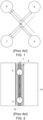
- the standard method to test for detecting transversal defects typically employs four (4) transducers arranged in an X-formation, creating a pitch-catch scenario, as illustrated in FIG. 1 .
- a transversal defect will reflect the signals to each other, i.e., from transducer number 6 to transducer number 5 or from transducer number 5 to transducer number 6.
- Transducers 5 and 7 also function as a coupling check for transducers 6 and 8.
- each single transducer can also check for a 45 degree oblique defect by firing and receiving within one cycle per transducer.
- Various X-formations are installed for internal and external detection scenarios.
- the X-formation is advantageous in terms of signal-to-noise and geometry tolerance.
- the sensitive area is restricted to the relatively small overlapping region of the sound fields from the representative transducers.
- the pitch-catch configuration is typically localized to inspecting the pipe surface.
- transducers 3 and 4 are positioned opposite each other on a weld seam 12 of a pipe 14 and function as a coupling check for themselves.
- the transducers 3, 4 can be positioned on the weld root 1 or the weld bead 2. Internal and external defects can be detected directly in a pulse-echo configuration. However, only when the transducers 3, 4 are positioned directly on the middle of the weld seam is the beam sufficiently confined to detect a transversal defect or notch correctly.
- transducers 3, 4 are misaligned, e.g., transducer 3 moved to the light, as illustrated in FIG. 3 , or if the weld root 1 and the weld bead 2 are not symmetrically positioned, the defect reflection will be deflected, as illustrated in FIG. 3 , leading to a strong sensitivity drop on the transducers.
- this system is intolerant of the geometry changes that may be present in a weld seam and may not identify all transversal defects in a weld seam.
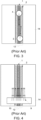
- An alternative system illustrated in FIG. 4 , employs phased array transducers 10 instead of single crystal transducers positioned over the weld seam 12 to emit ultrasonic signals 9.
- phased array transducers 10 instead of single crystal transducers positioned over the weld seam 12 to emit ultrasonic signals 9.
- the positioning of defects and their angular reflection characteristics can be mathematically modeled or determined by trial and error methods and the correct delay laws applied to selected virtual probes. In this way, the defect signals can be optimized for an increased range covering more or less the complete weld seam area.
- this approach may suffer from several drawbacks. First, if the geometry of the weld seam changes either within one pipe or from one pipe to another pipe, a new configuration of the virtual probes would be necessary.
- An advantage that may be realized in the practice of some disclosed embodiments of the method is deflections caused by non-uniformity of the geometry of the weld seam or misalignment of the defect can be compensated for as the signals reflected due to these geometries appear at a different position of the probe.
- Embodiments of the disclosed subject matter provide techniques for non-destructive inspection of a weld seam to identify defects.
- an array of ultrasonic transducers is positioned such that the array of transducers extends over the width of the weld seam.
- Each transducer element in the array of transducer elements is excited so that each transducer simultaneously emits an ultrasonic signal.
- a plurality of reflected ultrasonic signals are received at the array of transducer elements and the reflected ultrasonic signals are converted to electrical signals.
- At least one set of delay laws are applied to the electrical signals to generate a plurality of virtual probes steered to a plurality of angles.
- a defect is identified by at least one of the virtual probes.
- Other embodiments are within the scope of the disclosed subject matter.
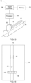
- FIGs. 5 and 6 illustrate a system 10 for non-destructively inspecting a weld seam 12.
- the weld seam 12 extends along the pipe 14 substantially parallel to the longitudinal axis A of the pipe 14.
- An ultrasonic sensor 16 is positioned over the weld seam 12.
- the ultrasonic sensor 16 is centered over the weld seam 12, i.e., positioned on-bead, such that the ultrasonic sensor 16, and particularly the element direction of the ultrasonic sensor 16, is substantially perpendicular to the weld seam 12.
- the ultrasonic sensor 16 is positioned at the root of the weld seam 12. Coupling between the ultrasonic sensor 16 and the pipe 14 is indirect.
- a column of liquid such as water or oil
- a column of liquid is positioned between the ultrasonic sensor 16 and the pipe 14 in a quasi-immersion technique.
- This column of liquid allows an efficient coupling between the ultrasonic sensor 16 and the pipe 14, even in cases of geometric variations of the weld seam 12.
- Ultrasonic waves emitted by the ultrasonic sensor 16 are propagated in the liquid and transmitted through the liquid to the pipe 14.
- the water column can be established by a wedge setup filled with water, squirters, or bubblers.
- a wheel probe is applied with the array 18, stabilizing the coupling process while still being tolerant to weld seam 12 geometries.
- a processor 22 can be coupled to the probe 16 and operable to analyze the reflected ultrasonic signals collected by the probe 16.
- a signal converter 26 can be coupled to the processor 22 for converting reflected ultrasonic signals to electrical signals.
- a memory 24 can be coupled to the processor 22 and/or signal converter 26 for storing the electrical signals.
- the ultrasonic sensor 16 includes one or more transducer elements 19, such as an array 18 of ultrasonic transducers.
- the array 18 includes a plurality of freely programmable transmitters.
- the array 18 of ultrasonic transducer elements 19 is sized and positioned such that when the array 18 of transducer elements 19 is placed over the weld seam 12, the array 18 of transducer elements 19 covers substantially the entire width W of the weld seam 12.
- the array 18 of transducer elements 19 can be a linear array, a two-dimensional array, or a three-dimensional array.
- the complexity of the array 18 can be selected based on the complexity of the geometry of the weld seam 12.
- the number of transducer elements 19 in the array 18 can be selected based on the desired size of the array 18. In an example, the number of transducer elements in the array 18 can be selected so that the array 18 is large enough to cover the entire width W of the weld seam 12. In an embodiment, the array 18 includes 64 transducer elements 19. In another embodiment, the array 18 includes 128 transducer elements 19.
- the array 18 of ultrasonic transducer elements 19 is operable in a pitch-catch or pulse-echo mode in which the transducer elements 19 emit ultrasonic signals and receive reflected ultrasonic signals.
- at least two ultrasonic sensors 16, 17 are positioned opposite each other on the weld seam 12.
- the ultrasonic sensors 16, 17 are positioned with a relative inclination angle in the range of 15 degrees to 19 degrees.
- the addition of this second ultrasonic sensor 17 enables a coupling check of the ultrasonic sensor 16.
- employing a second ultrasonic sensor 17 can enable detection of longitudinal defects.
- the array 18 of transducer elements 19 is operable to detect a defect 20 ( FIG. 6 ).
- a plurality of defects 20 can be detected in the weld seam 12.
- the defect 20 can be located on an outer or inner surface of the weld seam 12.
- the defect 20 can be a longitudinal defect, a transversal defect, or a lamination defect.
- the defect has a longitudinal component and a transverse component, the proportion of which is a function of the angle of the defect.
- the angle of the defect is defined relative to the longitudinal axis A of the pipe 14 and may be positive or negative.
- transversal defects having an inclination angle within the range of -80 degrees to +80degrees, such as -30 degrees to +30 degrees, -20 degrees to +20 degrees, or -15 degrees to +15 degrees can be detected.
- this method 30 employs the paint brush method.
- This method 30 can be employed by an ultrasonic inspection system, such as the system 10 ( FIG. 5 ) described above.
- an ultrasonic inspection system such as the system 10 ( FIG. 5 ) described above.
- at least one ultrasonic probe including an array 18 of ultrasonic transducer elements 19 is positioned over a weld seam 12 of a pipe 14.
- the transducer elements 19 of the sensor 16 are each excited to emit an ultrasound pulse wave or ultrasonic signal.
- the transducer elements 19 are controlled in such a manner that they emit at the same time, substantially without a phase shift or time delay. In other words, the "physical deflection on emission" is zero.
- the emitted ultrasonic signal is transmitted to the weld seam 12.
- An example of the transmitted signals is illustrated in FIG. 12 .
- the emitted signal interfaces with the weld seam 12
- the emitted signal is refracted.
- the emitted signal then travels from the weld seam 12 and the external surface of the pipe 14 to the internal surface of the pipe 14, is reflected back, and then travels to the external surface of the pipe and the weld seam 12 again, where the signal hits the weld bead 2 ( FIG. 2 ).
- the emitted signal covers the entire width W of the weld seam 12. In another embodiment, the emitted signal covers the entire width W of the weld seam 12 and a portion of the heat affected zone of the pipe 14.
- the emitted signal is continuous and homogeneous within the physical limits at its creation. Homogenity will be influenced by the geometrical deviations due to the weld bead or the weld root of the weld seam 12, but the continuity remains. As a consequence, the weld and the heat affected zone of the pipe 14 can be affected by the ultrasonic signal.
- the sensor 16 can be oriented so that it fires at the weld seam 12 in accordance with a transverse deflection angle ⁇ L in order to detect longitudinal defects or in accordance with an axial deflection angle ⁇ T in order to detect transverse defects.
- an ultrasonic signal 9 forms at an angle ⁇ T to the normal N of the pipe 14 in a longitudinal sectional plane of the longitudinal axis A of the pipe 14.
- an ultrasonic signal 9 emitted by the ultrasonic sensor 16 forms an angle ⁇ L relative to the normal N of the pipe 14, which is defined in a transverse section plane perpendicular to the longitudinal axis A of the pipe 14.
- deflections have varying values depending on the propagation medium and the material of the pipe 12 ( FIGs. 5 and 6 ) and weld seam 12.
- the angle ⁇ L is 17 degrees and the angle ⁇ T is zero while these values are reversed for detecting transverse defects.
- These values are adjusted for other angles of the defect 20.
- the angles ⁇ L and ⁇ T correspond to deflections of approximately 12 degrees in the transverse plane and the longitudinal plane, respectively.
- These values can be varied within a range, such as -15 degrees to +15 degrees, in order to detect defects 20 having various inclination angles.
- defects such as cracks
- the ultrasonic signal encounters an anomaly or defect 20 in the weld seam 12
- a portion of the ultrasonic signal is reflected.
- the way in which the ultrasonic signal is reflected depends on the defect shape, position, and orientation. As illustrated by FIG. 13 , the reflected signals follow the reverse of the path of the emitted signal.
- the ultrasonic signals reflected from the weld seam 12 are received by the transducer elements 19, again without a time delay.
- the ultrasonic waves reflected by an anomaly or defect 20 are sensed on return by the transducer elements 19 and, at block 36 ( FIG. 11 ), are converted into electrical signals, such as by the signal converter 26 ( FIG. 5 ).
- the signal converter 26 can be an analog-to-digital converter. These converted electrical signals can be stored in the memory 24 for later processing.
- the transmitted signals can also be converted to electrical signals and stored in the memory 24.
- the electrical signals, representing the transmitted and reflected ultrasonic signals are processed to generate a plurality of virtual probes.
- at least one set of delay laws are applied to the transmitted electrical signals and the corresponding reflected ultrasonic signals.
- the delay laws are selected by measuring time of flight between all of the transducer elements 19 and the surface of the weld seam 12 and extracting a delay law to apply to the electrical signals based on the measured time of flight.
- the applied delay laws can be selected so that an angular range indicated as a critical path is densely covered by test-shot angles, ensuring that at least one of the resulting virtual probes detects a defect 20.
- the delayed electrical signals are added up or summed to form the virtual probes, each virtual probe representing a probe 16 steered to a particular deflection angle.
- a "virtual" deflection of the beam is constructed on the reflected signals by staggering the instances at which the received signals are added up, for each transducer element 19.
- a visual representation 42 ( FIG. 14 ) of the summed signals can be generated.
- This visual representation 42 can take the form of an A-scan, B-scan, or any other suitable type of representation.
- a defect 20 in the weld seam 12 can be identified based on the plurality of virtual probes.
- the defect 20 is identified from the visual representation 42, e.g., A-scan, in which a defect signature 44 is present.
- an A-scan of the summed data is compared to an A-scan of the raw, unsummed data in order to identify the defect signature.
- a single defect 20 or a plurality of defects 20 in the weld seam 12 can be identified.
- the defect(s) 20 can be a transversal defect, a longitudinal defect, or a lamination defect.
- the defect 20 is a transversal defect having an inclination angle in the range of -90 degrees to +90 degrees, such as in the range of -15 degrees to +15 degrees.
- a time inversion algorithm can be applied to compensate for directional variation induced by the geometry of the weld seam 12.
- embodiments of the invention provide a method for non-destructively inspecting a weld seam to identify a defect.
- a technical effect is to compensate for non-uniformity of geometry or misalignment of the defect.
- aspects of the present invention may be embodied as a system, method, or computer program product. Accordingly, aspects of the present invention may take the form of an entirely hardware embodiment, an entirely software embodiment (including firmware, resident software, micro-code, etc.), or an embodiment combining software and hardware aspects that may all generally be referred to herein as a "service,” “circuit,” “circuitry,” “module,” and/or “system.” Furthermore, aspects of the present invention may take the form of a computer program product embodied in one or more computer readable medium(s) having computer readable program code embodied thereon.
- the computer readable medium may be a computer readable signal medium or a computer readable storage medium.
- a computer readable storage medium may be, for example, but not limited to, an electronic, magnetic, optical, electromagnetic, infrared, or semiconductor system, apparatus, or device, or any suitable combination of the foregoing.
- a computer readable storage medium may be any tangible medium that can contain, or store a program for use by or in connection with an instruction execution system, apparatus, or device.
- Program code and/or executable instructions embodied on a computer readable medium may be transmitted using any appropriate medium, including but not limited to wireless, wireline, optical fiber cable, RF, etc., or any suitable combination of the foregoing.
- Computer program code for carrying out operations for aspects of the present invention may be written in any combination of one or more programming languages, including an object oriented programming language such as Java, Smalltalk, C++ or the like and conventional procedural programming languages, such as the "C" programming language or similar programming languages.
- the program code may execute entirely on the user's computer (device), partly on the user's computer, as a stand-alone software package, partly on the user's computer and partly on a remote computer or entirely on the remote computer or server.
- the remote computer may be connected to the user's computer through any type of network, including a local area network (LAN) or a wide area network (WAN), or the connection may be made to an external computer (for example, through the Internet using an Internet Service Provider).
- LAN local area network
- WAN wide area network
- Internet Service Provider for example, AT&T, MCI, Sprint, EarthLink, MSN, GTE, etc.
- These computer program instructions may also be stored in a computer readable medium that can direct a computer, other programmable data processing apparatus, or other devices to function in a particular manner, such that the instructions stored in the computer readable medium produce an article of manufacture including instructions which implement the function/act specified in the flowchart and/or block diagram block or blocks.
- the computer program instructions may also be loaded onto a computer, other programmable data processing apparatus, or other devices to cause a series of operational steps to be performed on the computer, other programmable apparatus or other devices to produce a computer implemented process such that the instructions which execute on the computer or other programmable apparatus provide processes for implementing the functions/acts specified in the flowchart and/or block diagram block or blocks.
- At least one of in reference to a plurality of elements, this is intended to mean at least one or more of the listed elements, and is not limited to at least one of each element.
- at least one of an element A, element B, and element C is intended to indicate element A alone, or element B alone, or element C alone, or any combination thereof.
- At least one of element A, element B, and element C is not intended to be limited to at least one of an element A, at least one of an element B, and at least one of an element C.
Landscapes
- Physics & Mathematics (AREA)
- General Health & Medical Sciences (AREA)
- Life Sciences & Earth Sciences (AREA)
- Chemical & Material Sciences (AREA)
- Analytical Chemistry (AREA)
- Biochemistry (AREA)
- Health & Medical Sciences (AREA)
- General Physics & Mathematics (AREA)
- Immunology (AREA)
- Pathology (AREA)
- Acoustics & Sound (AREA)
- Engineering & Computer Science (AREA)
- Multimedia (AREA)
- Investigating Or Analyzing Materials By The Use Of Ultrasonic Waves (AREA)
Claims (13)
- Verfahren einer zerstörungsfreien Prüfung einer Schweißnaht (12), das Verfahren umfassend:Positionieren eines Ultraschallsensors (16), einschließlich einer Anordnung (18) von Wandlerelementen (19) über eine Schweißnaht (12) eines Rohrs (14), wobei sich die Schweißnaht (12) entlang des Rohrs (14) im Wesentlichen parallel zu einer Längsachse des Rohrs (14) erstreckt und wobei die Wandlerelemente (19) in einer Richtung im Wesentlichen senkrecht zu der Schweißnaht (12) angeordnet sind;Anregen jedes Wandlerelements (19) der Anordnung (18) von Wandlerelementen, um ein Ultraschallsignal zu emittieren, in dem die Anordnung von Wandlerelementen positioniert ist, um sich über mindestens einen Teil einer Breite der Schweißnaht (12) zu erstrecken;Empfangen einer Vielzahl von reflektierten Ultraschallsignalen an der Anordnung (18) von Wandlerelementen; undUmwandeln der reflektierten Ultraschallsignale in elektrische Signale;Messen der Laufzeit zwischen allen Wandlerelementen (19) und einer Oberfläche der Schweißnaht (12);Auswählen mindestens eines Satzes von Verzögerungsgesetzen basierend auf der gemessenen Laufzeit;Anwenden des ausgewählten mindestens einen Satzes von Verzögerungsgesetzen auf die elektrischen Signale, um eine Vielzahl von virtuellen Sonden zu erzeugen, die auf eine Vielzahl von Winkeln, Brennpunkten oder eine Kombination von Winkeln und Brennpunkten gesteuert werden; undIdentifizieren, durch mindestens eine der virtuellen Sonden, eines Fehlers (20) in der Schweißnaht (12).
- Verfahren nach Anspruch 1, wobei der Fehler einen Längsfehler einen Querfehler oder einen Laminierungsfehler umfasst.
- Verfahren nach Anspruch 1, wobei die Anordnung (18) von Wandlern mindestens teilweise in ein Fluid eingetaucht ist, um eine Übertragung der Ultraschallsignale zu ermöglichen.
- Verfahren nach Anspruch 1, wobei die Ultraschallsignale ohne eine Zeitverzögerung emittiert werden und die reflektierten Signale ohne Zeitverzögerung empfangen werden.
- Verfahren nach Anspruch 1, wobei das Anwenden des mindestens einen Satzes von Verzögerungsgesetzen eine Verzögerung bei der Übertragung des elektronischen Signals elektronisch anwendet, um den Strahl einer virtuellen Sonde auf einen bestimmten Winkel, bestimmte Brennpunkte oder eine Kombination von dem Winkel und Brennpunkten zu steuern.
- Verfahren nach Anspruch 5, wobei eine Vielfalt von virtuellen Sonden erzeugt wird, die in einem Bereich von Strahlwinkeln gesteuert werden.
- Verfahren nach Anspruch 1, wobei der Fehler (20) einen Neigungswinkel innerhalb eines Bereichs von -15 Grad bis 15 Grad umfasst.
- Verfahren nach Anspruch 1, wobei eine zweite Anordnung (17) von Wandlerelementen auf der Schweißnaht (12) gegenüber der Anordnung (18) von Wandlerelementen positioniert ist.
- Verfahren nach Anspruch 1, ferner umfassend ein Speichern der elektrischen Signale in einem Speicher (24).
- Verfahren nach Anspruch 1, wobei die Wandlerelemente (19) der Anordnung (18) von Ultraschallwandlerelementen das Ultraschallsignal gleichzeitig emittieren.
- Verfahren nach Anspruch 1, wobei die Anordnung (18) von Ultraschallwandlern positioniert ist, um sich über eine gesamte Breite der Schweißnaht (12) zu erstrecken.
- Verfahren nach Anspruch 1, ferner umfassend ein Erzeugen eines B-Scans oder eines geometriekorrigierten B-Scans.
- Verfahren nach Anspruch 12, ferner umfassend das Anwenden eines Bildverarbeitungsalgorithmus auf den B-Scan, um Bildmerkmale in Bezug auf einen potenziellen Fehler (20) zu erkennen oder charakterisieren.
Applications Claiming Priority (2)
| Application Number | Priority Date | Filing Date | Title |
|---|---|---|---|
| US201562117149P | 2015-02-17 | 2015-02-17 | |
| PCT/US2016/018244 WO2016134005A1 (en) | 2015-02-17 | 2016-02-17 | Method for inspecting a weld seam with ultrasonic phased array |
Publications (2)
| Publication Number | Publication Date |
|---|---|
| EP3259587A1 EP3259587A1 (de) | 2017-12-27 |
| EP3259587B1 true EP3259587B1 (de) | 2024-04-10 |
Family
ID=55451581
Family Applications (1)
| Application Number | Title | Priority Date | Filing Date |
|---|---|---|---|
| EP16707334.5A Active EP3259587B1 (de) | 2015-02-17 | 2016-02-17 | Verfahren zur inspektion von schweissnähten mit ultraschall-gruppenstrahlern |
Country Status (4)
| Country | Link |
|---|---|
| US (1) | US10921291B2 (de) |
| EP (1) | EP3259587B1 (de) |
| CA (1) | CA2978468C (de) |
| WO (1) | WO2016134005A1 (de) |
Families Citing this family (10)
| Publication number | Priority date | Publication date | Assignee | Title |
|---|---|---|---|---|
| CN112638549B (zh) | 2018-09-06 | 2022-07-12 | Abb瑞士股份有限公司 | 用于非侵入测量的换能器 |
| EP3847425A1 (de) | 2018-09-06 | 2021-07-14 | ABB Schweiz AG | Wandler zur nichtinvasiven messung |
| CN112639460A (zh) | 2018-09-06 | 2021-04-09 | Abb瑞士股份有限公司 | 用于无创测量的换能器 |
| SG10202001721UA (en) * | 2019-03-14 | 2020-10-29 | Gen Electric | Acoustic inspection device and method of operation |
| EP3797891B1 (de) * | 2019-09-30 | 2023-08-02 | Nexans | Verfahren zur kontinuierlichen herstellung abschnittsweise gewellter, dünnwandiger hohlprofile kleiner durchmesser aus ne-metallen |
| EP3797890B1 (de) * | 2019-09-30 | 2024-03-27 | Nexans | Verfahren zur herstellung dünnwandiger hohlprofile kleiner durchmesser aus ne-metallen |
| CN111189919B (zh) * | 2020-01-21 | 2023-08-25 | 岭澳核电有限公司 | 核电站管道焊缝检测装置 |
| US20220146460A1 (en) * | 2020-11-11 | 2022-05-12 | Southwest Research Institute | Guided wave testing of welds in pipelines and plate structures |
| US11994496B2 (en) | 2021-05-12 | 2024-05-28 | Ford Global Technologies, Llc | Non-destructive evaluation system for inspection of weld and braze joints |
| CN115389627A (zh) * | 2022-09-02 | 2022-11-25 | 中国航发北京航空材料研究院 | 一种识别异形制件变截面区域缺陷的超声无损检测方法 |
Citations (2)
| Publication number | Priority date | Publication date | Assignee | Title |
|---|---|---|---|---|
| WO2001071338A1 (en) * | 2000-03-24 | 2001-09-27 | Shaw Industries Ltd. | Ultrasonic testing |
| EP2574956A1 (de) * | 2011-09-30 | 2013-04-03 | GE Inspection Technologies Ltd | Ultraschallabbildungssystem und -verfahren mit Nebenkeulenunterdrückung durch Kohärenzfaktorwichtung |
Family Cites Families (7)
| Publication number | Priority date | Publication date | Assignee | Title |
|---|---|---|---|---|
| DE4109625A1 (de) * | 1991-03-23 | 1992-09-24 | Krautkraemer Gmbh | Ultraschall-messverfahren fuer den wanddickenverlauf einer schweissnaht eines rohres |
| US6789427B2 (en) * | 2002-09-16 | 2004-09-14 | General Electric Company | Phased array ultrasonic inspection method for industrial applications |
| US7694569B2 (en) * | 2004-08-24 | 2010-04-13 | General Electric Company | Phased array ultrasonic water wedge apparatus |
| JP4544240B2 (ja) * | 2005-11-21 | 2010-09-15 | Jfeスチール株式会社 | 管体の超音波探傷装置および超音波探傷方法 |
| US8365602B2 (en) * | 2009-10-09 | 2013-02-05 | Olympus Ndt, Inc. | Weld seam tracking system using phased array ultrasonic devices |
| US9037419B2 (en) * | 2011-05-10 | 2015-05-19 | Edison Welding Institute, Inc. | Portable matrix phased array spot weld inspection system |
| CA2803502C (en) * | 2012-01-26 | 2020-10-27 | Olympus Ndt Inc. | A phased array system and method for inspecting hellical submerged arcs weld (hsaw) |
-
2016
- 2016-02-17 CA CA2978468A patent/CA2978468C/en active Active
- 2016-02-17 EP EP16707334.5A patent/EP3259587B1/de active Active
- 2016-02-17 US US15/551,687 patent/US10921291B2/en active Active
- 2016-02-17 WO PCT/US2016/018244 patent/WO2016134005A1/en not_active Ceased
Patent Citations (2)
| Publication number | Priority date | Publication date | Assignee | Title |
|---|---|---|---|---|
| WO2001071338A1 (en) * | 2000-03-24 | 2001-09-27 | Shaw Industries Ltd. | Ultrasonic testing |
| EP2574956A1 (de) * | 2011-09-30 | 2013-04-03 | GE Inspection Technologies Ltd | Ultraschallabbildungssystem und -verfahren mit Nebenkeulenunterdrückung durch Kohärenzfaktorwichtung |
Also Published As
| Publication number | Publication date |
|---|---|
| US10921291B2 (en) | 2021-02-16 |
| EP3259587A1 (de) | 2017-12-27 |
| CA2978468C (en) | 2023-08-01 |
| WO2016134005A1 (en) | 2016-08-25 |
| CA2978468A1 (en) | 2016-08-25 |
| US20180067085A1 (en) | 2018-03-08 |
Similar Documents
| Publication | Publication Date | Title |
|---|---|---|
| CA2978468C (en) | Method for inspecting a weld seam with ultrasonic phased array | |
| EP2401606B1 (de) | Verfahren zur untersuchung von pipeline-schweissverbindungen mittels ultraschall-gruppenstrahlern | |
| US11353430B2 (en) | Phased array probe and method for testing a spot-weld | |
| US9810666B2 (en) | Device and method for nondestructive inspection of tubular products, especially on site | |
| JP4910770B2 (ja) | 管体の超音波探傷装置および超音波探傷方法 | |
| US9032802B2 (en) | Phased array system and method for inspecting helical submerged arcs weld (HSAW) | |
| US9672187B2 (en) | System and method for directing guided waves through structures | |
| US9347851B2 (en) | Signal processing of lamb wave data for pipe inspection | |
| WO2012103628A1 (en) | Method for ultrasonic inspection of welds | |
| US20230184720A1 (en) | Method and system for inspection of joints in composite pipes and of composite repairs in metallic pipelines | |
| JP2010025676A (ja) | 超音波探傷方法及び装置 | |
| JP2006138672A (ja) | 超音波検査方法及び装置 | |
| JP5847010B2 (ja) | 非破壊検査装置および非破壊検査方法 | |
| Jin et al. | Defect detection of spherical heads by time-of-flight diffraction | |
| Uzun et al. | Review of Phased Array Ultrasonic Testing of Weld Joints | |
| Hörchens et al. | Ultrasound imaging of stress corrosion cracking | |
| KR101163552B1 (ko) | 위상배열 초음파 탐상용 스텐레스강/듀플렉스강용 감도보정 대비시험편 | |
| Bertoncini et al. | 3D characterization of defects in Guided Wave monitoring of pipework using a magnetostrictive sensor | |
| Liu | Phased Array Ultrasonic Testing of Corrosive Resistant Alloy Girth Weld of Cladded Pipes using the Total Focusing Method | |
| Wassink et al. | Approaches for developing solutions for specific NDT problems | |
| UA78345C2 (en) | Method for complex diagnostics of welded connections of vessels and standard-simulator of separation zones for rolled shell rings for realization of this method |
Legal Events
| Date | Code | Title | Description |
|---|---|---|---|
| STAA | Information on the status of an ep patent application or granted ep patent |
Free format text: STATUS: THE INTERNATIONAL PUBLICATION HAS BEEN MADE |
|
| PUAI | Public reference made under article 153(3) epc to a published international application that has entered the european phase |
Free format text: ORIGINAL CODE: 0009012 |
|
| STAA | Information on the status of an ep patent application or granted ep patent |
Free format text: STATUS: REQUEST FOR EXAMINATION WAS MADE |
|
| 17P | Request for examination filed |
Effective date: 20170918 |
|
| AK | Designated contracting states |
Kind code of ref document: A1 Designated state(s): AL AT BE BG CH CY CZ DE DK EE ES FI FR GB GR HR HU IE IS IT LI LT LU LV MC MK MT NL NO PL PT RO RS SE SI SK SM TR |
|
| AX | Request for extension of the european patent |
Extension state: BA ME |
|
| DAV | Request for validation of the european patent (deleted) | ||
| DAX | Request for extension of the european patent (deleted) | ||
| STAA | Information on the status of an ep patent application or granted ep patent |
Free format text: STATUS: EXAMINATION IS IN PROGRESS |
|
| 17Q | First examination report despatched |
Effective date: 20190328 |
|
| P01 | Opt-out of the competence of the unified patent court (upc) registered |
Effective date: 20230526 |
|
| REG | Reference to a national code |
Ref country code: DE Ref legal event code: R079 Free format text: PREVIOUS MAIN CLASS: G01N0029260000 Ipc: G01N0029070000 Ref document number: 602016086806 Country of ref document: DE |
|
| GRAP | Despatch of communication of intention to grant a patent |
Free format text: ORIGINAL CODE: EPIDOSNIGR1 |
|
| STAA | Information on the status of an ep patent application or granted ep patent |
Free format text: STATUS: GRANT OF PATENT IS INTENDED |
|
| RIC1 | Information provided on ipc code assigned before grant |
Ipc: G01N 29/07 20060101AFI20231221BHEP |
|
| INTG | Intention to grant announced |
Effective date: 20240123 |
|
| GRAS | Grant fee paid |
Free format text: ORIGINAL CODE: EPIDOSNIGR3 |
|
| GRAA | (expected) grant |
Free format text: ORIGINAL CODE: 0009210 |
|
| STAA | Information on the status of an ep patent application or granted ep patent |
Free format text: STATUS: THE PATENT HAS BEEN GRANTED |
|
| AK | Designated contracting states |
Kind code of ref document: B1 Designated state(s): AL AT BE BG CH CY CZ DE DK EE ES FI FR GB GR HR HU IE IS IT LI LT LU LV MC MK MT NL NO PL PT RO RS SE SI SK SM TR |
|
| REG | Reference to a national code |
Ref country code: GB Ref legal event code: FG4D |
|
| REG | Reference to a national code |
Ref country code: CH Ref legal event code: EP |
|
| REG | Reference to a national code |
Ref country code: DE Ref legal event code: R096 Ref document number: 602016086806 Country of ref document: DE |
|
| REG | Reference to a national code |
Ref country code: IE Ref legal event code: FG4D |
|
| REG | Reference to a national code |
Ref country code: LT Ref legal event code: MG9D |
|
| REG | Reference to a national code |
Ref country code: NL Ref legal event code: MP Effective date: 20240410 |
|
| REG | Reference to a national code |
Ref country code: AT Ref legal event code: MK05 Ref document number: 1675386 Country of ref document: AT Kind code of ref document: T Effective date: 20240410 |
|
| PG25 | Lapsed in a contracting state [announced via postgrant information from national office to epo] |
Ref country code: NL Free format text: LAPSE BECAUSE OF FAILURE TO SUBMIT A TRANSLATION OF THE DESCRIPTION OR TO PAY THE FEE WITHIN THE PRESCRIBED TIME-LIMIT Effective date: 20240410 |
|
| PG25 | Lapsed in a contracting state [announced via postgrant information from national office to epo] |
Ref country code: NL Free format text: LAPSE BECAUSE OF FAILURE TO SUBMIT A TRANSLATION OF THE DESCRIPTION OR TO PAY THE FEE WITHIN THE PRESCRIBED TIME-LIMIT Effective date: 20240410 |
|
| PG25 | Lapsed in a contracting state [announced via postgrant information from national office to epo] |
Ref country code: IS Free format text: LAPSE BECAUSE OF FAILURE TO SUBMIT A TRANSLATION OF THE DESCRIPTION OR TO PAY THE FEE WITHIN THE PRESCRIBED TIME-LIMIT Effective date: 20240810 |
|
| PG25 | Lapsed in a contracting state [announced via postgrant information from national office to epo] |
Ref country code: BG Free format text: LAPSE BECAUSE OF FAILURE TO SUBMIT A TRANSLATION OF THE DESCRIPTION OR TO PAY THE FEE WITHIN THE PRESCRIBED TIME-LIMIT Effective date: 20240410 |
|
| PG25 | Lapsed in a contracting state [announced via postgrant information from national office to epo] |
Ref country code: FI Free format text: LAPSE BECAUSE OF FAILURE TO SUBMIT A TRANSLATION OF THE DESCRIPTION OR TO PAY THE FEE WITHIN THE PRESCRIBED TIME-LIMIT Effective date: 20240410 Ref country code: HR Free format text: LAPSE BECAUSE OF FAILURE TO SUBMIT A TRANSLATION OF THE DESCRIPTION OR TO PAY THE FEE WITHIN THE PRESCRIBED TIME-LIMIT Effective date: 20240410 |
|
| PG25 | Lapsed in a contracting state [announced via postgrant information from national office to epo] |
Ref country code: GR Free format text: LAPSE BECAUSE OF FAILURE TO SUBMIT A TRANSLATION OF THE DESCRIPTION OR TO PAY THE FEE WITHIN THE PRESCRIBED TIME-LIMIT Effective date: 20240711 |
|
| PG25 | Lapsed in a contracting state [announced via postgrant information from national office to epo] |
Ref country code: PT Free format text: LAPSE BECAUSE OF FAILURE TO SUBMIT A TRANSLATION OF THE DESCRIPTION OR TO PAY THE FEE WITHIN THE PRESCRIBED TIME-LIMIT Effective date: 20240812 |
|
| PG25 | Lapsed in a contracting state [announced via postgrant information from national office to epo] |
Ref country code: ES Free format text: LAPSE BECAUSE OF FAILURE TO SUBMIT A TRANSLATION OF THE DESCRIPTION OR TO PAY THE FEE WITHIN THE PRESCRIBED TIME-LIMIT Effective date: 20240410 |
|
| PG25 | Lapsed in a contracting state [announced via postgrant information from national office to epo] |
Ref country code: AT Free format text: LAPSE BECAUSE OF FAILURE TO SUBMIT A TRANSLATION OF THE DESCRIPTION OR TO PAY THE FEE WITHIN THE PRESCRIBED TIME-LIMIT Effective date: 20240410 |
|
| PG25 | Lapsed in a contracting state [announced via postgrant information from national office to epo] |
Ref country code: PL Free format text: LAPSE BECAUSE OF FAILURE TO SUBMIT A TRANSLATION OF THE DESCRIPTION OR TO PAY THE FEE WITHIN THE PRESCRIBED TIME-LIMIT Effective date: 20240410 |
|
| PG25 | Lapsed in a contracting state [announced via postgrant information from national office to epo] |
Ref country code: LV Free format text: LAPSE BECAUSE OF FAILURE TO SUBMIT A TRANSLATION OF THE DESCRIPTION OR TO PAY THE FEE WITHIN THE PRESCRIBED TIME-LIMIT Effective date: 20240410 |
|
| PG25 | Lapsed in a contracting state [announced via postgrant information from national office to epo] |
Ref country code: PT Free format text: LAPSE BECAUSE OF FAILURE TO SUBMIT A TRANSLATION OF THE DESCRIPTION OR TO PAY THE FEE WITHIN THE PRESCRIBED TIME-LIMIT Effective date: 20240812 Ref country code: PL Free format text: LAPSE BECAUSE OF FAILURE TO SUBMIT A TRANSLATION OF THE DESCRIPTION OR TO PAY THE FEE WITHIN THE PRESCRIBED TIME-LIMIT Effective date: 20240410 Ref country code: NO Free format text: LAPSE BECAUSE OF FAILURE TO SUBMIT A TRANSLATION OF THE DESCRIPTION OR TO PAY THE FEE WITHIN THE PRESCRIBED TIME-LIMIT Effective date: 20240710 Ref country code: LV Free format text: LAPSE BECAUSE OF FAILURE TO SUBMIT A TRANSLATION OF THE DESCRIPTION OR TO PAY THE FEE WITHIN THE PRESCRIBED TIME-LIMIT Effective date: 20240410 Ref country code: IS Free format text: LAPSE BECAUSE OF FAILURE TO SUBMIT A TRANSLATION OF THE DESCRIPTION OR TO PAY THE FEE WITHIN THE PRESCRIBED TIME-LIMIT Effective date: 20240810 Ref country code: HR Free format text: LAPSE BECAUSE OF FAILURE TO SUBMIT A TRANSLATION OF THE DESCRIPTION OR TO PAY THE FEE WITHIN THE PRESCRIBED TIME-LIMIT Effective date: 20240410 Ref country code: GR Free format text: LAPSE BECAUSE OF FAILURE TO SUBMIT A TRANSLATION OF THE DESCRIPTION OR TO PAY THE FEE WITHIN THE PRESCRIBED TIME-LIMIT Effective date: 20240711 Ref country code: FI Free format text: LAPSE BECAUSE OF FAILURE TO SUBMIT A TRANSLATION OF THE DESCRIPTION OR TO PAY THE FEE WITHIN THE PRESCRIBED TIME-LIMIT Effective date: 20240410 Ref country code: ES Free format text: LAPSE BECAUSE OF FAILURE TO SUBMIT A TRANSLATION OF THE DESCRIPTION OR TO PAY THE FEE WITHIN THE PRESCRIBED TIME-LIMIT Effective date: 20240410 Ref country code: BG Free format text: LAPSE BECAUSE OF FAILURE TO SUBMIT A TRANSLATION OF THE DESCRIPTION OR TO PAY THE FEE WITHIN THE PRESCRIBED TIME-LIMIT Effective date: 20240410 Ref country code: AT Free format text: LAPSE BECAUSE OF FAILURE TO SUBMIT A TRANSLATION OF THE DESCRIPTION OR TO PAY THE FEE WITHIN THE PRESCRIBED TIME-LIMIT Effective date: 20240410 Ref country code: RS Free format text: LAPSE BECAUSE OF FAILURE TO SUBMIT A TRANSLATION OF THE DESCRIPTION OR TO PAY THE FEE WITHIN THE PRESCRIBED TIME-LIMIT Effective date: 20240710 |
|
| REG | Reference to a national code |
Ref country code: DE Ref legal event code: R097 Ref document number: 602016086806 Country of ref document: DE |
|
| PG25 | Lapsed in a contracting state [announced via postgrant information from national office to epo] |
Ref country code: DK Free format text: LAPSE BECAUSE OF FAILURE TO SUBMIT A TRANSLATION OF THE DESCRIPTION OR TO PAY THE FEE WITHIN THE PRESCRIBED TIME-LIMIT Effective date: 20240410 |
|
| PG25 | Lapsed in a contracting state [announced via postgrant information from national office to epo] |
Ref country code: EE Free format text: LAPSE BECAUSE OF FAILURE TO SUBMIT A TRANSLATION OF THE DESCRIPTION OR TO PAY THE FEE WITHIN THE PRESCRIBED TIME-LIMIT Effective date: 20240410 |
|
| PG25 | Lapsed in a contracting state [announced via postgrant information from national office to epo] |
Ref country code: CZ Free format text: LAPSE BECAUSE OF FAILURE TO SUBMIT A TRANSLATION OF THE DESCRIPTION OR TO PAY THE FEE WITHIN THE PRESCRIBED TIME-LIMIT Effective date: 20240410 |
|
| PG25 | Lapsed in a contracting state [announced via postgrant information from national office to epo] |
Ref country code: RO Free format text: LAPSE BECAUSE OF FAILURE TO SUBMIT A TRANSLATION OF THE DESCRIPTION OR TO PAY THE FEE WITHIN THE PRESCRIBED TIME-LIMIT Effective date: 20240410 Ref country code: SK Free format text: LAPSE BECAUSE OF FAILURE TO SUBMIT A TRANSLATION OF THE DESCRIPTION OR TO PAY THE FEE WITHIN THE PRESCRIBED TIME-LIMIT Effective date: 20240410 |
|
| PG25 | Lapsed in a contracting state [announced via postgrant information from national office to epo] |
Ref country code: SM Free format text: LAPSE BECAUSE OF FAILURE TO SUBMIT A TRANSLATION OF THE DESCRIPTION OR TO PAY THE FEE WITHIN THE PRESCRIBED TIME-LIMIT Effective date: 20240410 |
|
| PG25 | Lapsed in a contracting state [announced via postgrant information from national office to epo] |
Ref country code: SM Free format text: LAPSE BECAUSE OF FAILURE TO SUBMIT A TRANSLATION OF THE DESCRIPTION OR TO PAY THE FEE WITHIN THE PRESCRIBED TIME-LIMIT Effective date: 20240410 Ref country code: SK Free format text: LAPSE BECAUSE OF FAILURE TO SUBMIT A TRANSLATION OF THE DESCRIPTION OR TO PAY THE FEE WITHIN THE PRESCRIBED TIME-LIMIT Effective date: 20240410 Ref country code: RO Free format text: LAPSE BECAUSE OF FAILURE TO SUBMIT A TRANSLATION OF THE DESCRIPTION OR TO PAY THE FEE WITHIN THE PRESCRIBED TIME-LIMIT Effective date: 20240410 Ref country code: EE Free format text: LAPSE BECAUSE OF FAILURE TO SUBMIT A TRANSLATION OF THE DESCRIPTION OR TO PAY THE FEE WITHIN THE PRESCRIBED TIME-LIMIT Effective date: 20240410 Ref country code: DK Free format text: LAPSE BECAUSE OF FAILURE TO SUBMIT A TRANSLATION OF THE DESCRIPTION OR TO PAY THE FEE WITHIN THE PRESCRIBED TIME-LIMIT Effective date: 20240410 Ref country code: CZ Free format text: LAPSE BECAUSE OF FAILURE TO SUBMIT A TRANSLATION OF THE DESCRIPTION OR TO PAY THE FEE WITHIN THE PRESCRIBED TIME-LIMIT Effective date: 20240410 |
|
| PG25 | Lapsed in a contracting state [announced via postgrant information from national office to epo] |
Ref country code: IT Free format text: LAPSE BECAUSE OF FAILURE TO SUBMIT A TRANSLATION OF THE DESCRIPTION OR TO PAY THE FEE WITHIN THE PRESCRIBED TIME-LIMIT Effective date: 20240410 |
|
| PLBE | No opposition filed within time limit |
Free format text: ORIGINAL CODE: 0009261 |
|
| STAA | Information on the status of an ep patent application or granted ep patent |
Free format text: STATUS: NO OPPOSITION FILED WITHIN TIME LIMIT |
|
| 26N | No opposition filed |
Effective date: 20250113 |
|
| PG25 | Lapsed in a contracting state [announced via postgrant information from national office to epo] |
Ref country code: SI Free format text: LAPSE BECAUSE OF FAILURE TO SUBMIT A TRANSLATION OF THE DESCRIPTION OR TO PAY THE FEE WITHIN THE PRESCRIBED TIME-LIMIT Effective date: 20240410 |
|
| PG25 | Lapsed in a contracting state [announced via postgrant information from national office to epo] |
Ref country code: SE Free format text: LAPSE BECAUSE OF FAILURE TO SUBMIT A TRANSLATION OF THE DESCRIPTION OR TO PAY THE FEE WITHIN THE PRESCRIBED TIME-LIMIT Effective date: 20240410 |
|
| PG25 | Lapsed in a contracting state [announced via postgrant information from national office to epo] |
Ref country code: MC Free format text: LAPSE BECAUSE OF FAILURE TO SUBMIT A TRANSLATION OF THE DESCRIPTION OR TO PAY THE FEE WITHIN THE PRESCRIBED TIME-LIMIT Effective date: 20240410 |
|
| REG | Reference to a national code |
Ref country code: CH Ref legal event code: PL |
|
| PG25 | Lapsed in a contracting state [announced via postgrant information from national office to epo] |
Ref country code: LU Free format text: LAPSE BECAUSE OF NON-PAYMENT OF DUE FEES Effective date: 20250217 |
|
| PG25 | Lapsed in a contracting state [announced via postgrant information from national office to epo] |
Ref country code: CH Free format text: LAPSE BECAUSE OF NON-PAYMENT OF DUE FEES Effective date: 20250228 |
|
| GBPC | Gb: european patent ceased through non-payment of renewal fee |
Effective date: 20250217 |
|
| REG | Reference to a national code |
Ref country code: BE Ref legal event code: MM Effective date: 20250228 |
|
| PG25 | Lapsed in a contracting state [announced via postgrant information from national office to epo] |
Ref country code: GB Free format text: LAPSE BECAUSE OF NON-PAYMENT OF DUE FEES Effective date: 20250217 |
|
| PG25 | Lapsed in a contracting state [announced via postgrant information from national office to epo] |
Ref country code: FR Free format text: LAPSE BECAUSE OF NON-PAYMENT OF DUE FEES Effective date: 20250228 |
|
| PG25 | Lapsed in a contracting state [announced via postgrant information from national office to epo] |
Ref country code: BE Free format text: LAPSE BECAUSE OF NON-PAYMENT OF DUE FEES Effective date: 20250228 |
|
| PG25 | Lapsed in a contracting state [announced via postgrant information from national office to epo] |
Ref country code: IE Free format text: LAPSE BECAUSE OF NON-PAYMENT OF DUE FEES Effective date: 20250217 |
|
| PGFP | Annual fee paid to national office [announced via postgrant information from national office to epo] |
Ref country code: DE Payment date: 20260121 Year of fee payment: 11 |