EP3258989B1 - Ambulatory infusion pump with static and dynamic seals - Google Patents
Ambulatory infusion pump with static and dynamic seals Download PDFInfo
- Publication number
- EP3258989B1 EP3258989B1 EP16713140.8A EP16713140A EP3258989B1 EP 3258989 B1 EP3258989 B1 EP 3258989B1 EP 16713140 A EP16713140 A EP 16713140A EP 3258989 B1 EP3258989 B1 EP 3258989B1
- Authority
- EP
- European Patent Office
- Prior art keywords
- plunger
- assembly
- reservoir
- seal
- disposable
- Prior art date
- Legal status (The legal status is an assumption and is not a legal conclusion. Google has not performed a legal analysis and makes no representation as to the accuracy of the status listed.)
- Active
Links
Images


Classifications
-
- A—HUMAN NECESSITIES
- A61—MEDICAL OR VETERINARY SCIENCE; HYGIENE
- A61M—DEVICES FOR INTRODUCING MEDIA INTO, OR ONTO, THE BODY; DEVICES FOR TRANSDUCING BODY MEDIA OR FOR TAKING MEDIA FROM THE BODY; DEVICES FOR PRODUCING OR ENDING SLEEP OR STUPOR
- A61M5/00—Devices for bringing media into the body in a subcutaneous, intra-vascular or intramuscular way; Accessories therefor, e.g. filling or cleaning devices, arm-rests
- A61M5/14—Infusion devices, e.g. infusing by gravity; Blood infusion; Accessories therefor
- A61M5/142—Pressure infusion, e.g. using pumps
- A61M5/14244—Pressure infusion, e.g. using pumps adapted to be carried by the patient, e.g. portable on the body
-
- A—HUMAN NECESSITIES
- A61—MEDICAL OR VETERINARY SCIENCE; HYGIENE
- A61M—DEVICES FOR INTRODUCING MEDIA INTO, OR ONTO, THE BODY; DEVICES FOR TRANSDUCING BODY MEDIA OR FOR TAKING MEDIA FROM THE BODY; DEVICES FOR PRODUCING OR ENDING SLEEP OR STUPOR
- A61M5/00—Devices for bringing media into the body in a subcutaneous, intra-vascular or intramuscular way; Accessories therefor, e.g. filling or cleaning devices, arm-rests
- A61M5/14—Infusion devices, e.g. infusing by gravity; Blood infusion; Accessories therefor
- A61M5/142—Pressure infusion, e.g. using pumps
- A61M5/145—Pressure infusion, e.g. using pumps using pressurised reservoirs, e.g. pressurised by means of pistons
- A61M5/1452—Pressure infusion, e.g. using pumps using pressurised reservoirs, e.g. pressurised by means of pistons pressurised by means of pistons
-
- A—HUMAN NECESSITIES
- A61—MEDICAL OR VETERINARY SCIENCE; HYGIENE
- A61M—DEVICES FOR INTRODUCING MEDIA INTO, OR ONTO, THE BODY; DEVICES FOR TRANSDUCING BODY MEDIA OR FOR TAKING MEDIA FROM THE BODY; DEVICES FOR PRODUCING OR ENDING SLEEP OR STUPOR
- A61M5/00—Devices for bringing media into the body in a subcutaneous, intra-vascular or intramuscular way; Accessories therefor, e.g. filling or cleaning devices, arm-rests
- A61M5/178—Syringes
- A61M5/31—Details
- A61M5/315—Pistons; Piston-rods; Guiding, blocking or restricting the movement of the rod or piston; Appliances on the rod for facilitating dosing ; Dosing mechanisms
- A61M5/31511—Piston or piston-rod constructions, e.g. connection of piston with piston-rod
- A61M5/31513—Piston constructions to improve sealing or sliding
-
- A—HUMAN NECESSITIES
- A61—MEDICAL OR VETERINARY SCIENCE; HYGIENE
- A61M—DEVICES FOR INTRODUCING MEDIA INTO, OR ONTO, THE BODY; DEVICES FOR TRANSDUCING BODY MEDIA OR FOR TAKING MEDIA FROM THE BODY; DEVICES FOR PRODUCING OR ENDING SLEEP OR STUPOR
- A61M5/00—Devices for bringing media into the body in a subcutaneous, intra-vascular or intramuscular way; Accessories therefor, e.g. filling or cleaning devices, arm-rests
- A61M5/14—Infusion devices, e.g. infusing by gravity; Blood infusion; Accessories therefor
- A61M5/142—Pressure infusion, e.g. using pumps
- A61M5/14244—Pressure infusion, e.g. using pumps adapted to be carried by the patient, e.g. portable on the body
- A61M2005/14264—Pressure infusion, e.g. using pumps adapted to be carried by the patient, e.g. portable on the body with means for compensating influence from the environment
Definitions
- the present devices and methods relate generally to ambulatory infusion pumps and seals for those pumps.
- Ambulatory infusion pumps are relatively small, at least substantially self-contained devices that are used to introduce drugs and other infusible substances (collectively “medicament") into patients' bodies.
- Some infusion pumps are configured to be worn on a belt, carried in a clothing pocket, or the like.
- Other infusion pumps are configured to be adhered to skin in patch-like fashion.
- Infusion pumps are advantageous in that they may be used to, for example, subcutaneously introduce (or “infuse") medicament on an ongoing or even continuous basis outside of a clinical environment.
- Infusion pumps are also advantageous in that they greatly reduce the frequency of subcutaneous access events such as needle-based shots.
- a medicament that may be introduced by an infusion pump is a liquid formulation of insulin.
- Other exemplary medicaments that may be introduced by an infusion pump include, but are not limited to, drugs that treat cancers and drugs that suppress the perception of pain.
- the specification describes structures and methods that are especially well-suited for the subcutaneous delivery of very high concentration insulin (i.e., U-200 insulin and above) such as U-500 insulin as well as lower concentration insulin such as U-100 insulin.
- the present inventions are applicable to a wide variety of infusion pumps and medicaments.
- the inventions may employ, for fluid displacement, a reservoir with a plunger, a fluid displacement device in the form of a plunger pusher, and a drive mechanism that includes a motor, or other fluid displacement devices, regardless of the type of reservoir employed, piston pumps (e.g., electromagnet pumps), MEMS pumps, peristaltic pumps and any other suitable pumps as well as corresponding drive mechanisms.
- Exemplary infusion pumps that include a reservoir with a plunger, a fluid displacement device in the form of a plunger pusher, and a drive mechanism are described in U.S. patent application serial number 12/890,207, filed September 24, 2010 , and corresponding U.S. patent publication number 2012/0078170 , and in U.S. provisional patent application serial number 62/057,273, filed September 30, 2014 , and corresponding U.S. patent application serial number 14/869,906, filed September 29, 2015 .
- the present inventions are also applicable to medicaments such as, for example, drugs to mask pain, chemotherapy and other cancer related drugs, antibiotics, hormones, GLP-1, Glucagon, various other drugs that include large molecules and proteins that may require a high level of delivery accuracy, as well as to relatively high concentration insulin (i.e., U-200 insulin and above) such as U-500 insulin and lower concentration insulin such as U-100.
- medicaments such as, for example, drugs to mask pain, chemotherapy and other cancer related drugs, antibiotics, hormones, GLP-1, Glucagon, various other drugs that include large molecules and proteins that may require a high level of delivery accuracy, as well as to relatively high concentration insulin (i.e., U-200 insulin and above) such as U-500 insulin and lower concentration insulin such as U-100.
- Aforementioned U.S. patent publication number 2012/0078170 , U.S. provisional patent application serial number 62/057,273 and U.S. patent application serial number 14/869,906 each also describe patient interaction with and use
- some ambulatory infusion pumps are intended to be worn on a belt, carried in a pocket, or otherwise supported within a holder of some kind (referred to collectively as “pocket pumps”).
- Such infusion pumps transfer fluid from a reservoir to an infusion set by way of an elongate tube.
- Subcutaneous access may be obtained by way of a cannula in the infusion set.
- Other ambulatory infusion pumps are intended to be adhered to the skin above the delivery site (sometimes referred to as "patch pumps”).
- the cannula or other subcutaneous access device may extend directly from the infusion device.
- patients typically prefer the device to be as small as possible so it is more comfortable, less obtrusive, and less visible.
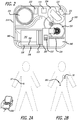
- An exemplary ambulatory infusion system which is generally represented by reference numeral 100 in FIGS. 1A, 1B , and 2 , includes a durable assembly 200 and a disposable assembly 300.
- Exemplary durable assembly 200 includes a housing 202, one or more batteries or other energy supply 221, one or more capacitors or other energy storage 222, a microprocessor 223, a coil assembly 224 (which functions as a motor stator), and one or more Hall effect sensors 225.
- Exemplary disposable assembly 300 includes a baseplate 350 supporting components such as a magnetic motor rotor 331, a gear train 332 including lead screw drive gear 333 in a reservoir support block 337, and a lead screw 334 attached to plunger 335, which is positioned in a medicament reservoir 336 that is mounted to the reservoir support block 337.
- the exemplary plunger 335 includes a core and a plurality of seals on the core.
- a cover 302, under which some or all of the magnetic motor rotor 331, gear train 332 (with drive gear 333), lead screw 334, plunger 335, and medicament reservoir 336 are located in various embodiments, may be mounted to the baseplate 350.
- the lead screw drive gear 333, lead screw 334, plunger 335, medicament reservoir 336 and reservoir support block 337 may also be referred to collectively as a "reservoir assembly.”
- Other exemplary reservoir assemblies that may be employed in, for example, infusion system 100 are described below with reference to FIGS. 10-23 .
- the exemplary disposable assembly 300 may be secured to the exemplary durable assembly 200, as shown in FIGS. 1A and 2 .
- the exemplary housing 202 includes a top wall 204, bottom walls 206a and 206b and a side wall 208 that together define a relatively thin housing portion 210 and a relatively thick housing portion 212.
- An indentation 214 is formed in the relatively thick portion 212.
- the exemplary cover 302 includes top walls 304a and 304b and a side wall 306 that together define a relatively thin cover portion 308 and a relatively thick cover portion 310.
- a portion of the baseplate 350 is not covered by the cover 302, thereby defining a recess 312 that is bordered by a wall 314 that extends around the baseplate (see also FIG. 4B ).
- the relatively thick portion 212 of the housing 202 will reside in the recess 312 of the disposable assembly 300 (with the wall 314 in the indentation 214).
- the relatively thin portion 210 of the housing 202 will reside on the top wall 304b of the cover 302.
- the cover 302 also includes a projection 316 that mates with a recess 216 on the housing 202.
- the disposable assembly 300 may be configured for different medicaments, such as different medicament concentrations, different medicament amounts, or different modes of system operation.
- the cover 302 may be configured to cover fewer than all of the components on the baseplate 350.
- a cover may be configured such that the magnetic motor rotor 331 and a portion of the gear train 332 are not under the cover, while the remaining components are under the cover.
- the cover 302 may be omitted and the durable assembly 200 may be configured to cover all of the components on the baseplate 350.
- what is referred to in the present application as the "durable" assembly may be disposable, resulting in a fully disposable system.
- ambulatory infusion systems that employ a reservoir on a baseplate may be configured for different types of use.
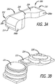
- disposable assembly 300 may be adhered to the patient's skin and may be used in conjunction with a cannula (not shown) that is operatively connected to the reservoir 336 so that the system 100 may be deployed as a "patch-pump," as shown in FIG.
- the baseplate 350 of disposable assembly 300 may be configured to operably connect the reservoir 336 to an infusion set 382 (e.g., by way of the illustrated infusion set tube and a connector 380 shown in FIGS. 1B and 2 ) so that the system 100 may be deployed as a "pocket pump," a "belt-worn pump” or some other wearable pump.
- the user may configure the system for use as "pocket pump” or a "patch pump” by simply selecting the appropriate disposable assembly and attaching the disposable assembly to the durable assembly. The user may also switch from one configuration to another, by simply removing one disposable assembly and replacing it with another disposable assembly.
- kits that contain various combinations of disposable assemblies, where at least two of the disposable assemblies may be different. Additionally or alternatively, kits or other packages may include various disposable assembly components, such as an infusion set and/or cannula inserter. Kits may also include a durable assembly. The disposable assemblies in such kits may also include the detection/identification instrumentalities discussed below.
- the components of the present kits e.g., combination of various disposable assemblies and/or components
- a recharger may also be provided in a kit that includes a durable assembly.
- the different disposable assemblies may include visual cues to differentiate the various disposable assemblies. For instance, disposable assemblies with different concentrations of medicament or different medicament fill volumes may use different colors for the reservoir and/or baseplate of the disposable assembly, or mechanical features that ensure disposables are only able to attach to correctly programmed durables.
- the dispensing procedures associated with an infusion system "patch pump” configuration which may include a durable assembly 200 and a disposable assembly 300, are substantially the same as the dispensing procedures associated with a "pocket pump” configuration, which may also include an infusion set 382 (see FIGS. 2B ).
- a "patch pump” configuration priming is not necessary because the volume of the associated cannula will be very small and there is a direct connection between the cannula and the medicament reservoir. Priming is, however, required to fill the infusion set tube ( FIG. 2B ) in a "pocket pump” configuration prior to the onset of medicament delivery.
- the priming procedure may involve the rapid delivery of 10-15 IUs of U-500 insulin to the tube.
- the present inventors have determined that it would be advantageous to prevent users from initiating a priming procedure when the system is in the "patch pump" configuration, with a cannula positioned to deliver medicament essentially directly from the medicament reservoir to the patient, because rapidly delivering 10-15 IUs of insulin to the patient could adversely affect patient health.
- At least some of the present disposable assemblies may be provided with a baseplate identification device and at least some of the present disposable assemblies may be provided with structure that cooperate with a baseplate identification device in such a manner that the durable assembly microprocessor/controller can make a "baseplate type" determination.
- Exemplary baseplate identification instrumentalities and methodologies may be as described in aforementioned U.S. patent publication numbers 2012/0078170 , 2012/0184907 , and 2013/0138078 .
- baseplate identification may be performed mechanically. For instance, a pin or rib may prevent attachment of certain disposable assemblies with certain durable assemblies. Additionally or alternative, certain durable assemblies will simply not function with certain disposable assemblies.
- the patient or a clinician may program the system, such as via a remote control, to indicate the type of disposable assembly attached.
- a patient can access a variety of medicaments for use with a single durable assembly.
- the durable assembly will proceed in a manner, or mode of operation, that is appropriate for the attached disposable assembly. For example, if “patch pump” disposable assembly 300 is detected, the durable assembly controller will not include priming as part of the delivery process and, in some implementations, will prevent the user from manually implementing a priming procedure. If, on the other hand, a "pocket pump” disposable assembly is detected, then the delivery process may include appropriate priming of the infusion set tube.
- the system may be configured to provide basal delivery of medicament in accordance with a delivery profile provided by a physician by way of a clinician's programming unit.
- the system may include a program that stores a number of delivery profiles (e.g., delivery profiles associated with a 24-hour delivery cycle, delivery profiles for particular situations such as sleep or illness, and the like).
- Each delivery profile specifies multiple doses (or pump "operations") over time, e.g., a particular number of doses at particular times or a particular number of doses per unit time.
- a dose may be the volume associated with the minimum controllable displacement of the plunger 335.
- the system may also be configured to provide bolus delivery in response to an instruction from a patient remote control 1000 ( FIG. 2A ).
- a bolus instruction may come in response to a high glucose level measurement in the case of a diabetic patient, an increase in pain level in the case of a pain management patient, or some other symptom.
- the system may also be configured to perform other functions, such as ending medicament delivery in response to instructions from patient remote control 1000.
- the present infusion pumps may be used in conjunction with a wide variety of remote controls.
- Such remote controls may be used to, for example, allow the user to transmit instructions to the durable assembly 200 or facilitate communication between durable assembly 200 and the user (e.g., an alarm condition message or other message concerning the conditions of system 100).
- An exemplary remote control 1000 ( FIG. 1
- 2A may be configured to facilitate one, some, or all of the following operations: (1) turning the remote control 1000 on or off, (2) associating (or “assigning") the remote control 1000 to the durable assembly 20, (3) obtaining status information such as medicament level, battery charge level, and/or alarm conditions, (4) silencing the durable assembly alarm, (5) selecting options that may be associated with the durable assembly alarm such as type of alarm (audible, palpable, and/or visible) and strength/volume of alarm, (6) connecting remote control 1000 to a computer to, for example, update remote control or durable assembly firmware, load and delete delivery profiles stored in the durable assembly or remote control, and otherwise reprogram the durable assembly or remote control, (7) selecting medicament options such as medicament concentrations, (8) selecting and initiating a stored medicament delivery profile, (9) increasing and decreasing medicament dose rate, and/or (10) pausing a dispensing operation.
- a user may pause delivery in order to remove or replace a patient applied structure (e.g., a disposable assembly), adjust for a current or anticipated changed body condition (e.g., low glucose, vigorous exercise), follow a physician's suggestion, or disconnect the durable assembly from the body for any other reason.
- a patient applied structure e.g., a disposable assembly
- a current or anticipated changed body condition e.g., low glucose, vigorous exercise
- the exemplary remote control 1000 may be configured to generate an indicator, based on information from a microprocessor 223 for durable assembly 200, that is indicative of, for instance, the amount of time remaining in the current dispensing program, the amount of time until the next disposable assembly replacement, etc.
- the indicator may be audible, visible, palpable, or combinations thereof.
- a time remaining indicator may be useful for a variety of reasons. For example, knowledge of the time remaining prior to next disposable assembly replacement allows the patient to determine, based at least in part on the current time of day and upcoming events (e.g., travel or sleep), whether or not it would be more convenient to replace the disposable assembly at a time prior to the end of the dispensing program.
- the durable assembly 200 which may include structures such as microprocessor 223 and coil assembly 224, is reusable, while exemplary disposable assemblies 300, which may include structures such as a motor rotor 331 and reservoir 336 on a baseplate 350, are disposable.
- some embodiments of the exemplary infusion pump system 100 may have the following dimensions: length dimensions of 35 mm +/- 1.0 mm, 35 mm +/- 0.10 mm, or 35 mm +/- 5.0 mm; width dimensions of 30 mm +/- 1.0 mm, 30 mm +/- 0.10 mm, or 30 mm +/- 5 mm; and overall thickness or height dimensions of 8.5 mm +/- 1.0 mm, 8.5 mm +/- 2 mm, or 8.5 mm +/- 0.10 mm.
- Suitable housing materials include, but are not limited to, plastic or other materials having a modulus of elasticity of 0.2-1.0 million psi.
- Exemplary durable assembly microprocessors and associated circuitry rechargeable batteries and associated battery rechargers and recharging methods; battery and recharging management; temperature sensors; and exemplary alarms and alarm conditions are described in more detail in aforementioned U.S. patent publication numbers 2012/0078170 , 2012/0184907 , and 2013/0138078 .
- an exemplary durable assembly 200 may include a power source such as one or more batteries 221, temporary power storage such as one or more capacitors 222 (see FIGS. 2 and 5B ), a controller such as microprocessor 223, a coil assembly 224, and a hall effect sensor 225.
- a power source such as one or more batteries 221
- temporary power storage such as one or more capacitors 222 (see FIGS. 2 and 5B )
- microprocessor 223 controls the microprocessor 223, a coil assembly 224, and a hall effect sensor 225.
- the microprocessor 223 provides flexibility to include features such as user data storage, programs, programmability, adjustability, a display, buttons, wireless communication protocols, or the like to the pump 100.
- Durable assembly 200 may also be molded with locking features that snap onto the disposable assembly 300, but that also allow removal of the durable assembly 200 from the disposable assembly 300 either while the disposable assembly remains in place on the patient (after medicament delivery has been paused), or after the entire system has been removed from the patient.
- the power source may be one or more commercially available batteries, such as a commercially available zinc-air battery or lithium polymer battery.
- the batteries may be selected to have sufficient capacity to operate the system for certain delivery amounts or delivery times, such as for over 400 units of delivered insulin.
- the optional power storage may be one or more commercially available capacitors or super-capacitors or other temporary storage device(s).
- an exemplary disposable assembly 300 may include baseplate 350 and components such as a reservoir 336, a plunger 335 within the reservoir and connected to lead screw 334, and a magnetic motor rotor 331 mechanically attached through gear train 332 to affect rotation of the lead screw drive gear 333, which causes translation of the lead screw 334 and plunger 335 within reservoir 336.
- the cover 302 is positioned over these components in the illustrated embodiment.
- the exemplary baseplate 350 includes an adhesive backing for attachment to the patient with a removable adhesive cover.
- the baseplate 350 may also be molded with baseplate locking features that snap onto the durable assembly 200 (such as magnets molded into the housings of each assembly), and that also allows removal of the durable assembly 200 from the disposable assembly 300.
- the exemplary reservoir 336 includes a barrel 338 with an inner surface 340 defining a fluid storage volume 342 and an oval cross-section, but other shapes (such as circular) are possible as is discussed below with reference to FIGS. 10-23 .
- a plunger 335 with a matching cross-sectional shape fits within the barrel and carries a fluid seal such as, but not limited to, o-rings, to seal the medicament within the storage volume 342.
- the exemplary plunger 335 is formed from rubber and includes three o-ring seals.
- the reservoir 336 includes a connector 380 that may be used for filling reservoir 336, or for attaching a cannula for "patch-pump” type configurations, or for connecting (potentially via an appropriate adapter(s)) an infusion set for "pocket-pump” type configurations.
- the plunger 335 moves within the barrel 338 to vary the volume of medicament within the storage volume 342.
- Reservoir 336 may be, for instance, prefilled (or user-filled) with U-500 insulin in various volumes to suit the patient use profile. In other instances, lower concentrations of insulin, such as U-100 insulin and U-200 insulin, may be employed.
- a plug may be inserted in the connector 380 to maintain a sterile environment until use. The patient would remove the plug prior to use, in those instances.
- Additional exemplary baseplates for use with the disposable assemblies of the present inventions, as well as exemplary cannula designs, fluidic connection between a medicament reservoir and the cannula, cooperation between the cannula and disposable assemblies (for instance, to prevent axial movement of the cannula relative to the baseplate and patient), attachment of an infusion set to the reservoir of the disposable assembly, configurations and uses of a non-delivery baseplate, arrangements and structures for attaching disposable and durable assemblies, skin adhesive designs, and various occlusion sensors, may be as described in U.S. patent application serial number 12/890,207, filed September 24, 2010 and corresponding U.S. patent publication number 2012/0078170 , as well as aforementioned U.S. patent publication numbers 2012/0184907 and 2013/0138078 .
- the motor's coil assembly 224 (and a Hall effect sensor 225) of the durable assembly 200 are positioned above the magnetic motor rotor 331 that is part of the disposable assembly 300.
- An exemplary multi-pole motor rotor 331 may be disc-shaped and have a 9.8 mm outer diameter, 5.2 mm inner diameter, and 0.8 mm thickness.
- Another example motor rotor may have an 11 mm outer diameter, 5 mm inner diameter, and 1.2 mm thickness. Multi-pole motor rotors of this type typically cost less than 5 cents per piece, helping control the total cost of disposable assembly 200.
- the motor rotor 331 is also parallel to the baseplate 350, i.e., the motor rotor axis of rotation is perpendicular to the baseplate, in the illustrated embodiment.
- the microprocessor 223 directs rotation of motor rotor 331 by sequentially energizing the coils of motor coil assembly 224 to create an electromagnetic torque coupling between the motor coil assembly 224 and the motor rotor 331.
- the position/orientation of the rotor's poles relative to the rotating magnetic field generator (coil assembly 224) is measured by back EMF, a rotary encoder, a hall effect sensor 225 ( FIG. 5A ), or the like.
- a Hall effect sensor mounted on the coil windings may be used to supply the microprocessor a count, a tachometer signal, or rotor position, allowing low-cost closed-loop control of the rotor speed.
- Brushless motors of this type are typically 85-90% or more efficient, and run very cool. While there may be variations in construction, the face-to-face stator coils and flat rotor plate shown in FIGS. 5A-5C provide a compact design. In addition, more coils and/or Hall effect sensors may be used.
- gap 240 between the motor coil assembly 224 and motor rotor 331 is a gap 240.
- Some or all of the gap 240 may be defined by (and occupied by) portions of the housing 202 and the cover 302, i.e., the housing bottom wall 206a and the cover top wall 304b in the illustrated implementation.
- the gap 240 between the between the motor coil assembly 224 and motor rotor 331 may be occupied by only a portion of the durable assembly housing, or only a portion of the disposably assembly cover, or no structure at all and may simply be an air gap.
- the size of the gap which is defined by the distance between the motor coil assembly 224 and the motor rotor 331, is typically about 0.5 mm to 2.0 mm.
- a patient's use of the exemplary infusion pump systems involves obtaining a new disposable assembly 300, connecting the disposable assembly to the durable assembly 200, peeling the liner from the baseplate adhesive layer, gaining subcutaneous access, and initiating a medicament delivery operation.
- use may involve additional steps such as attaching a cannula to connector 380 of the disposable assembly and removing a cannula cap, if necessary.
- Various aspects of the basic operation of the present systems are described below. Operation of a system does not necessarily require all of the steps each time the system is deployed, and the order of some of the steps may be changed.
- use of the present systems may involve removal of a disposable assembly from a durable assembly and the replacement of the disposable assembly. This may occur when the medicament reservoir is empty (as described in more detail in U.S. patent application serial number 12/890,207 and corresponding U.S. patent publication number 2012/0078170 ) (Step S101) and a "replace disposable assembly" message or alert is presented (Step S102), or when the durable assembly controller receives a user-initiated "replace disposable assembly” signal from a remote control 1000 (Step S103).
- the user may desire to replace a disposable assembly before the medicament reservoir is empty for a variety of reasons such as, for example, to accommodate the user's sleep or travel schedule, when the medicament exhibits a loss of effectiveness, when a dispensing problem arises, or due to a prescribed change in medicament.
- the user may then obtain, possibly from storage in a refrigerator depending on medicament requirements, a new pre-filled disposable assembly 300 or may then obtain a new disposable assembly and fill the disposable assembly with medicament (Step S104).
- the durable assembly 200 and disposable assembly 300 may then be removed from the skin, separated, and the disposable assembly 300 discarded (Steps S106 and S107).
- the new disposable assembly 300 may be attached to the durable assembly 200 (Step S109).
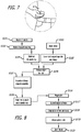
- the user should clean the skin surface S onto which the baseplate 350 of disposable assembly 300 will be adhered ( FIG. 7 , and Step S116 of FIG. 8 ).
- the user peels off the baseplate adhesive liner to expose the baseplate adhesive layer (Step S117) and removes cannula cap (when present) (Step S118).
- the disposable assembly 30 is supplied with a cannula in fluid communication with the reservoir storage volume.
- a cannula inserter may be attached to the system, which may be triggered to insert the cannula after the system is placed against the skin. Exemplary inserters are described in U.S.
- the system 100 including durable assembly 200 and disposable assembly 300 may be positioned over a suitable body location and pressed gently to adhere the adhesive layer to the skin surface S and, once the system has been adhered (Step S119), the inserter may be actuated to position the end of a cannula below the skin.
- the inserter may be actuated to position the end of a cannula below the skin.
- the remote control 1000 may be used to initiate a particular medicament delivery operation (Step S120).
- the delivery operation may follow a predetermined delivery profile (e.g. a particular basal rate, a series of time-spaced bolus deliveries, or some combination thereof) that is equated to motor rotor rotations, at particular rates and times, required to deliver medicament in accordance with the profile.
- the profile may be input by the user with the remote control 1000 and stored by the durable assembly microprocessor.
- the remote control may store a number of different delivery profiles and bolus deliveries from which the patient can choose. Such profiles may correspond to, for example and depending on the medicament, days where vigorous exercise is expected, days where it is not, incidences of increased pain, etc.
- the profile stored in the durable assembly microprocessor may be set by a clinician's programming unit.
- a remote control may not be needed to initiate, e.g., basal delivery.
- FIG. 9 Another exemplary ambulatory infusion system, which is generally represented by reference numeral 100a in FIG. 9 , includes a durable assembly 200a and a disposable assembly 300a.
- System 100a is substantially similar to system 100. Here, however, the intersection of the top walls is primarily linear.
- the disposable assembly 300a has a recess 316a which mates with a corresponding projection 216a on the durable assembly 200a. The projection 216a and recess 316a are located at the outer perimeter of the assembled system 100a.
- the reservoirs may also be, but are not required to be, prefilled.
- Prefilled reservoirs are advantageous for a variety of reasons. By way of example, but not limitation, some users prefer to avoid reservoir filling procedures because they are inconvenient and tend to involve needles. User-based refilling also increases the likelihood that air bubbles will be introduced into the reservoir, while prefilling by the manufacturer of the reservoir and/or the medicament can be accomplished without any substantial introduction of air bubbles using, for example, a vacuum filling procedure. Nevertheless, user-filled reservoirs may be employed in some instances.
- a variety of exemplary medicament reservoirs, including those that include pressure sensors (such as for sensing occlusion) and other sensors, are described in more detail in aforementioned U.S. patent publication numbers 2012/0078170 , 2012/0184907 , and 2013/0138078 .
- a solution to this challenge is provided with a dual seal system.
- Each seal type has a distinct function and can therefore be designed ideally for that use.
- a first seal type is a static seal. When the pump is in storage, this seal minimizes water vapor loss. As will be seen below, this seal may be fixed into position within the reservoir assembly support block or on the plunger core. Since the static seal only functions during storage, it can be designed to function with relatively large contact stresses and soft, sticky materials, such as bromobutyl rubber, to seal against water vapor loss.
- a second seal type is a dynamic seal. This seal is designed as a low glide/break force seal that operates when the plunger is moving during dispensing, but it also must be compatible with long term insulin storage. When dispensing commences, the static seal automatically disengages, minimizing the forces required to move the plunger during dispensing.
- the exemplary pump reservoir assembly 400 illustrated therein which may be employed in the exemplary ambulatory infusion system 100 described above or other infusion systems, includes a lead screw 434 engaged to a lead screw drive gear 433 and attached to plunger 435, which is positioned in a medicament reservoir 436.
- the reservoir 436 includes a barrel 438 with an inner surface 440 defining a fluid storage volume 442.
- the reservoir barrel 438 which may be formed from COP, COC, or the like, to maintain medicament (e.g., insulin) stability, is bonded or otherwise attached to support block 437 after the interior components (e.g., lead screw drive gear 433, lead screw 434, and plunger 435) are assembled.
- the end of the reservoir barrel 438 includes a connector 480.
- the exemplary plunger 435 includes a plunger core 460 that is bonded or otherwise attached to lead screw 434 and carries at least one dynamic seal 462 that is in contact with the inner surface 440 of the reservoir barrel 438.
- Plunger core 460 may be made of a relatively rigid material such as COP, COC, or the like, to maintain medicament (e.g., insulin) stability
- the dynamic seal(s) 462 may be made of a low friction resilient material, such as low friction plastic, parylene-coated rubber, Teflon-coated rubber, silicone-coated rubber, or the like.
- the dynamic seals 462 are o-ring seals.
- the plunger 435 slides within reservoir barrel 438 to dispense medicament.
- drive gear 433 rotates from torque supplied by a drive mechanism, such as magnetic motor rotor 331 and a gear train 332 in FIG. 2 , to cause translation of the plunger 435.
- the exemplary plunger 435 is in the "full position" when no medicament has been dispensed and the reservoir 436 is full. This may also be called the storage position, since the reservoir 436 is generally full during storage.
- the reservoir assembly 400 (as well as reservoir assemblies 400a and 400b (discussed below) may also be user-filled. In some instances where the reservoir assembly is user-filled, the plunger 435 will initially be located adjacent to the connector 480 and will move, in a direction opposite the dispensing direction, from there to the full position as the reservoir 436 is filled.
- Radial static seal 464 engages plunger core 460 to affect a static vapor seal.
- Radial static seal 464 may have various cross-sectional shapes and be attached to support block 437 in various ways.
- radial static seal 464 may be an O-ring.
- radial static seal 464 may be an O-ring that fits into an O-ring groove.
- the vapor seal may be achieved via an interference fit between radial static seal 464 and a static sealing surface 466 of plunger core 460.
- radial static seal 464 may have an inner diameter that is smaller than the outer diameter of the static sealing surface 466.
- the sealing surface 466 of plunger core 460 that is engaged by static seal(s) 464 may be designed to aid the vapor seal. For instance, this sealing surface 466 may be a slightly protruding circular surface. The interference between the plunger core sealing surface 466 and the radial static seal 464 causes elastomeric deformation of the seal 464 to create a vapor seal.
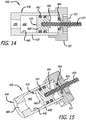
- the plunger 435 moves in a dispensing direction away from the full position ( FIGS. 10 and 13 ). For instance, in the orientation used for FIGS. 14 and 15 , the plunger 435 translates left as medicament is dispensed. When dispensing begins, the plunger 435 begins to translate left and the sealing surface 466 of the plunger core 460 slides off the radial static seal(s) 464.
- the plunger 435 automatically disengages from the static vapor seal(s) 464, while contact between the dynamic seal(s) 462 and the inner surface 440 of the reservoir barrel 438 is maintained, when the plunger moves out of the full position (or "storage position”); that is, no additional steps or actions are required to deactivate the static vapor seal(s) 464 while the dynamic seal(s) 462 remain active, to separate sealing surface 466 from static seal(s) 464 while the dynamic seal(s) 462 remain in contact with the barrel inner surface 440, or to allow dispensing to begin.
- the static vapor seal(s) 464 and the plunger 435 are disengaged from one another in response to a predetermined amount of movement of the plunger 435 in the dispensing direction out of the full position.
- the movement of the plunger 435 in the dispensing direction results in the static seal(s) 464 coming out of contact with the surface to which it is engaged to prevent vapor migration.
- the static seal(s) 464 are stationary; static seal(s) 464 do not need to change position in order for dispensing to begin or for the plunger 435 to move out of the full/storage position.
- radial static seal(s) 464 may be made of bromobutyl rubber or other relatively soft sealing material, for excellent long-term water vapor loss.
- the diameter of the sealing surface 466 of plunger core 460 may be kept as small as possible.
- the radial sealing contact at sealing surface 466 provides an excellent vapor seal, which is especially important for long-term storage. Since the static seal(s) 464 are not engaged during dispensing, a low plunger 435 glide force may be achieved. This results in reduced energy consumption, which allows use of, for instance, primary battery(ies) as a power source. This is well suited to infusion systems that benefit from energy efficiency, such as the exemplary ambulatory infusion system 100 described above with reference to FIGS. 1A, 1B , and 2 , since it is desirable to use no more energy than is actually needed.
- the exemplary reservoir assembly 400a illustrated in FIGS. 16-19 is substantially similar to reservoir assembly 400 and similar elements are represented by similar reference numerals.
- the dynamic seals may be integral with the plunger core.
- the exemplary plunger 435a includes a plunger core 460a that may be molded or machined from a relatively rigid material (e.g., COP, COC, or the like) and includes integral sealing ridges 462a to achieve the dynamic seal.
- a radial energizing spring 468 may be positioned within plunger core 460a.
- the radial energizing spring 468 radially deforms plunger core 460a to force sealing ridges 462a into a low friction, sealing contact with the inside surface 440 of reservoir barrel 438.
- the exemplary static seal 464a may be one or more face-type static seals that engage(s) the rear surface of plunger core 460a when no medicament has been dispensed, the reservoir 436 is full (e.g., during storage), and the plunger 435a is in the "full position” or “storage position”.
- Static face seal 464a may be made of bromobutyl rubber or other low-water-vapor-transmitting elastomers, for excellent long-term water vapor loss prevention.
- the static face seal 464a and the rear surface of plunger core 460a are in contact, resulting in a vapor seal. In the example shown in FIG. 16 , this seal is formed between the static face seal 460a and a static sealing surface 470 on the plunger core 460a.
- the plunger 435a moves away from the full/storage position, i.e., translates left (in the illustrated orientation) as medicament is dispensed.
- the plunger 435a begins to translate left ( FIG. 19 ), and the sealing surface 470 of the plunger core 460a loses contact with static face seal(s) 464a.
- the plunger 435a automatically disengages from the static vapor seal(s) 464a, while contact between the dynamic seal(s) 462a and the inner surface 440 of the reservoir barrel 438 is maintained, when the plunger moves out of the full position (or "storage position”); that is, no additional steps or actions are required to deactivate the static face seal(s) 464a while the dynamic seal(s) 462a remain active, to separate static seal 464a from static sealing surface 270 while the dynamic seal(s) 462a remain in contact with the barrel inner surface 440, or to allow dispensing to begin.
- static seal 464a is stationary; static seal 464a does not need to change position in order for dispensing to begin or for plunger 435a to move out of the full/storage position. Put another way, the static vapor seal(s) 464a and the plunger 435a are disengaged from one another in response to a predetermined amount of movement of the plunger 435a in the dispensing direction out of the full position.
- static seal 464a is not engaged during dispensing, the glide force required to translate plunger 435a during dispensing is determined by the choice of materials for the reservoir barrel 438, plunger core 460a (when the dynamic seals are integral sealing ridges 462a), and the strength of radial energizing spring 468.
- static seal(s) 464a are instead positioned on the back side of the plunger core 460a (i.e., the surface of plunger core 460a that faces support block 437a), so that the sealing surface is instead on the surface of support block 437a that faces the back surface of plunger core 460a.
- the static sealing surface 470 of plunger core 460a loses contact with static face seal 464a with minimal break-force required.
- the exemplary reservoir assembly 400b is substantially similar to reservoir assembly 400a and similar elements are represented by similar reference numerals.
- a helper spring 472 provides a force in just the small fraction of the distance that the plunger 435a travels through a reservoir barrel 438, such as only in about the first 1 mm, and then may lose contact with the plunger 435a.
- the helper spring 472 may be a disk spring (a.k.a., conical spring, conical washer, or Bellville spring). Multiple other spring types are possible, such as a coil spring, leaf spring, helical lock washer, curved washer, wave spring (a.k.a., wave washer or wavy washer), other compression spring or torsion spring, or the like.
- helper spring 240 (or similar spring that performs the same function) are also possible.
- a helper spring could be attached to a different portion of support block 437 and engage a different surface of plunger 435a.
- a helper spring could be positioned on the back surface of plunger 435a and push against a surface on support block 437.
- the helper spring can work with other types of static vapor seals, such as radial static seal 464, and/or with other types of dynamic seals, such as seal(s) 462.
- the natural compressive elasticity of the seal may act as a spring trying to push the plunger out. In such a case, the static face seal may act as the helper spring.
- a static seal(s) to address water vapor loss, in conjunction with separate dynamic seal(s) that are active during dispensing, allows optimization of the materials and material properties desired for the sealing surfaces, rather than trying to achieve both acceptable glide forces during dispensing and low water vapor loss during storage with just one type of sealing surface. Further, use of a static seal that automatically disengages when dispensing commences reduces the torque, and thus the energy, required to commence and continue dispensing. Thus, excellent dynamic sealing properties and excellent long-term static sealing properties may be achieved, while also conserving energy.
Landscapes
- Health & Medical Sciences (AREA)
- Vascular Medicine (AREA)
- Engineering & Computer Science (AREA)
- Anesthesiology (AREA)
- Biomedical Technology (AREA)
- Heart & Thoracic Surgery (AREA)
- Hematology (AREA)
- Life Sciences & Earth Sciences (AREA)
- Animal Behavior & Ethology (AREA)
- General Health & Medical Sciences (AREA)
- Public Health (AREA)
- Veterinary Medicine (AREA)
- Infusion, Injection, And Reservoir Apparatuses (AREA)
- Pharmaceuticals Containing Other Organic And Inorganic Compounds (AREA)
Description
- The present devices and methods relate generally to ambulatory infusion pumps and seals for those pumps.
- Ambulatory infusion pumps (also referred to herein simply as "infusion pumps") are relatively small, at least substantially self-contained devices that are used to introduce drugs and other infusible substances (collectively "medicament") into patients' bodies. Some infusion pumps are configured to be worn on a belt, carried in a clothing pocket, or the like. Other infusion pumps are configured to be adhered to skin in patch-like fashion. Infusion pumps are advantageous in that they may be used to, for example, subcutaneously introduce (or "infuse") medicament on an ongoing or even continuous basis outside of a clinical environment. Infusion pumps are also advantageous in that they greatly reduce the frequency of subcutaneous access events such as needle-based shots. One example of a medicament that may be introduced by an infusion pump is a liquid formulation of insulin. Other exemplary medicaments that may be introduced by an infusion pump include, but are not limited to, drugs that treat cancers and drugs that suppress the perception of pain.
- Many conventional infusion pumps have improved patient health and quality of life. Nevertheless, the present inventors have determined that conventional infusion pumps are susceptible to a wide range of improvements. By way of example, but not limitation, the present inventors have determined that it would be desirable to provide an infusion pump that is smaller, simpler, and less costly than conventional infusion pumps, while also being more accurate than conventional infusion pumps.
- From the United States patent application publication
US 2011/238015 A1 a unidirectional injector with a cylinder-piston unit is known. - From the United States patent application publication
US 2009/0166978 A1 a cylinder/piston unit as usable in the infusion pump reservoir assembly according toclaim 1 is known. - It is an object of the invention to minimize the braking forces required for a plunger to lose contact with a static seal.
- This and other objects are achieved by the infusion pump reservoir assembly according to the characterizing part of
claim 1 and the infusion pump according to claim 6 including the infusion pump reservoir assembly according toclaim 1. Further advantageous embodiments are claimed in the dependent claims. - Detailed description of exemplary embodiments will be made with reference to the accompanying drawings.
-
FIG. 1A is a perspective view of an exemplary infusion pump system in an assembled state. -
FIG. 1B is an exploded perspective view of the infusion pump system illustrated inFIG. 1A , including a durable assembly and a disposable assembly. -
FIG. 2 is a top view of certain components of the infusion pump system illustrated inFIGS. 1A and 1B . -
FIGS. 2A is a schematic view showing a use of the infusion pump system illustrated inFIGS. 1A and 1B . -
FIG. 2B is a schematic view showing another use of the infusion pump system illustrated inFIGS. 1A and 1B . -
FIG. 3A is a perspective view of an exemplary durable assembly. -
FIG. 3B is a perspective view of certain components of the durable assembly illustrated inFIG. 3A . -
FIG. 4A is a perspective view of an exemplary disposable assembly. -
FIG. 4B is a perspective view of certain components of the disposable assembly illustrated inFIG. 4A . -
FIG. 5A is a perspective view of certain components of a durable assembly and a disposable assembly of an exemplary infusion pump system. -
FIG. 5B is a perspective view of the components of the exemplary durable assembly illustrated inFIG. 5A . -
FIG. 5C is a perspective view of the components of the exemplary disposable assembly illustrated inFIG. 5A . -
FIG. 6 is a perspective section view of components of the exemplary infusion pump system ofFIG. 5A , revealing a gap between certain components of the durable and disposable assemblies. -
FIG. 7 is a front view showing a patient's skin being cleaned. -
FIG. 8 is a flow chart illustrating an exemplary disposable assembly removal and replacement method. -
FIG. 9 is a perspective view of an exemplary infusion pump system in an assembled state. -
FIG. 10 is a perspective view of an exemplary reservoir assembly with the plunger in the full position. -
FIG. 11 is a perspective view of certain components of the reservoir assembly illustrated inFIG. 10 . -
FIG. 12 is a perspective view of certain components of the reservoir assembly illustrated inFIG. 10 . -
FIG. 13 is a section view of the reservoir assembly illustrated inFIG. 10 . -
FIG. 14 is a section view of the reservoir assembly illustrated inFIG. 10 with the plunger not in the full position. -
FIG. 15 is a section perspective view of the reservoir assembly illustrated inFIG. 10 with the plunger not in the full position. -
FIG. 16 is a perspective view of an exemplary reservoir assembly with the plunger in the full position. -
FIG. 17 is a perspective view of certain components of the reservoir assembly illustrated inFIG. 16 . -
FIG. 18 is a perspective view of certain components of the reservoir assembly illustrated inFIG. 16 . -
FIG. 19 is a section view of the reservoir assembly illustrated inFIG. 16 with the plunger not in the full position. -
FIG. 20 is a section view of an exemplary reservoir assembly with the plunger in the full position. -
FIG. 21 is an enlarged view of a portion of aFIG. 20 . -
FIG. 22 is a section view of the reservoir assembly illustrated inFIG. 20 with the plunger not in the full position. -
FIG. 23 is an enlarged view of a portion ofFIG. 22 . - The following is a detailed description of the best presently known modes of carrying out the inventions. This description is not to be taken in a limiting sense, but is made merely for the purpose of illustrating the general principles of the inventions.
- It should also be noted here that the specification describes structures and methods that are especially well-suited for the subcutaneous delivery of very high concentration insulin (i.e., U-200 insulin and above) such as U-500 insulin as well as lower concentration insulin such as U-100 insulin. Nevertheless, it should be appreciated that the present inventions are applicable to a wide variety of infusion pumps and medicaments. By way of example, but not limitation, the inventions may employ, for fluid displacement, a reservoir with a plunger, a fluid displacement device in the form of a plunger pusher, and a drive mechanism that includes a motor, or other fluid displacement devices, regardless of the type of reservoir employed, piston pumps (e.g., electromagnet pumps), MEMS pumps, peristaltic pumps and any other suitable pumps as well as corresponding drive mechanisms. Exemplary infusion pumps that include a reservoir with a plunger, a fluid displacement device in the form of a plunger pusher, and a drive mechanism are described in
U.S. patent application serial number 12/890,207, filed September 24, 2010 U.S. patent publication number 2012/0078170 , and inU.S. provisional patent application serial number 62/057,273, filed September 30, 2014 U.S. patent application serial number 14/869,906, filed September 29, 2015 - The present inventions are also applicable to medicaments such as, for example, drugs to mask pain, chemotherapy and other cancer related drugs, antibiotics, hormones, GLP-1, Glucagon, various other drugs that include large molecules and proteins that may require a high level of delivery accuracy, as well as to relatively high concentration insulin (i.e., U-200 insulin and above) such as U-500 insulin and lower concentration insulin such as U-100. Aforementioned
U.S. patent publication number 2012/0078170 ,U.S. provisional patent application serial number 62/057,273 U.S. patent application serial number 14/869,906 each also describe patient interaction with and use of infusion pumps such as the exemplary infusion pumps described herein. - As noted above, some ambulatory infusion pumps are intended to be worn on a belt, carried in a pocket, or otherwise supported within a holder of some kind (referred to collectively as "pocket pumps"). Such infusion pumps transfer fluid from a reservoir to an infusion set by way of an elongate tube. Subcutaneous access may be obtained by way of a cannula in the infusion set. Other ambulatory infusion pumps are intended to be adhered to the skin above the delivery site (sometimes referred to as "patch pumps"). Here, the cannula or other subcutaneous access device may extend directly from the infusion device. Given these modes of use, patients typically prefer the device to be as small as possible so it is more comfortable, less obtrusive, and less visible. In addition, patients want a device that is easy and convenient to use.
- An exemplary ambulatory infusion system, which is generally represented by
reference numeral 100 inFIGS. 1A, 1B , and2 , includes adurable assembly 200 and adisposable assembly 300. Exemplarydurable assembly 200 includes ahousing 202, one or more batteries orother energy supply 221, one or more capacitors orother energy storage 222, amicroprocessor 223, a coil assembly 224 (which functions as a motor stator), and one or moreHall effect sensors 225. Exemplarydisposable assembly 300 includes abaseplate 350 supporting components such as amagnetic motor rotor 331, agear train 332 including leadscrew drive gear 333 in areservoir support block 337, and alead screw 334 attached toplunger 335, which is positioned in amedicament reservoir 336 that is mounted to thereservoir support block 337. Theexemplary plunger 335 includes a core and a plurality of seals on the core. Acover 302, under which some or all of themagnetic motor rotor 331, gear train 332 (with drive gear 333),lead screw 334,plunger 335, andmedicament reservoir 336 are located in various embodiments, may be mounted to thebaseplate 350. - The lead
screw drive gear 333,lead screw 334,plunger 335,medicament reservoir 336 andreservoir support block 337 may also be referred to collectively as a "reservoir assembly." Other exemplary reservoir assemblies that may be employed in, for example,infusion system 100 are described below with reference toFIGS. 10-23 . - The exemplary
disposable assembly 300 may be secured to the exemplarydurable assembly 200, as shown inFIGS. 1A and2 . To that end, theexemplary housing 202 includes atop wall 204,bottom walls side wall 208 that together define a relativelythin housing portion 210 and a relativelythick housing portion 212. Anindentation 214 is formed in the relativelythick portion 212. Theexemplary cover 302 includestop walls side wall 306 that together define a relativelythin cover portion 308 and a relativelythick cover portion 310. A portion of thebaseplate 350 is not covered by thecover 302, thereby defining arecess 312 that is bordered by awall 314 that extends around the baseplate (see alsoFIG. 4B ). When the durable anddisposable assemblies FIG. 1A , the relativelythick portion 212 of thehousing 202 will reside in therecess 312 of the disposable assembly 300 (with thewall 314 in the indentation 214). The relativelythin portion 210 of thehousing 202 will reside on thetop wall 304b of thecover 302. Thecover 302 also includes aprojection 316 that mates with arecess 216 on thehousing 202. Additionally, as is discussed in greater detail below, thedisposable assembly 300 may be configured for different medicaments, such as different medicament concentrations, different medicament amounts, or different modes of system operation. - In other implementations, the
cover 302 may be configured to cover fewer than all of the components on thebaseplate 350. For example, a cover may be configured such that themagnetic motor rotor 331 and a portion of thegear train 332 are not under the cover, while the remaining components are under the cover. In still other implementations, thecover 302 may be omitted and thedurable assembly 200 may be configured to cover all of the components on thebaseplate 350. In yet other implementations, what is referred to in the present application as the "durable" assembly, may be disposable, resulting in a fully disposable system. - As discussed in
U.S. patent publication number 2012/0078170 described above, and inU.S. application Serial No. 13/300,574, filed November 19, 2011 U.S. patent publication number 2012/0184907 , and inU.S. application Serial No. 13/475,843, filed May 18, 2012 U.S. patent publication number 2013/0138078 , ambulatory infusion systems that employ a reservoir on a baseplate may be configured for different types of use. For example,disposable assembly 300 may be adhered to the patient's skin and may be used in conjunction with a cannula (not shown) that is operatively connected to thereservoir 336 so that thesystem 100 may be deployed as a "patch-pump," as shown inFIG. 2A . Alternatively, as shown inFIGS. 2B , thebaseplate 350 ofdisposable assembly 300 may be configured to operably connect thereservoir 336 to an infusion set 382 (e.g., by way of the illustrated infusion set tube and aconnector 380 shown inFIGS. 1B and2 ) so that thesystem 100 may be deployed as a "pocket pump," a "belt-worn pump" or some other wearable pump. In other words, using the samedurable assembly 200, the user may configure the system for use as "pocket pump" or a "patch pump" by simply selecting the appropriate disposable assembly and attaching the disposable assembly to the durable assembly. The user may also switch from one configuration to another, by simply removing one disposable assembly and replacing it with another disposable assembly. - It should therefore be noted that the present inventions include kits that contain various combinations of disposable assemblies, where at least two of the disposable assemblies may be different. Additionally or alternatively, kits or other packages may include various disposable assembly components, such as an infusion set and/or cannula inserter. Kits may also include a durable assembly. The disposable assemblies in such kits may also include the detection/identification instrumentalities discussed below. The components of the present kits (e.g., combination of various disposable assemblies and/or components) may be stored in a common package, with individual packages for each component if necessary, and provided to the user in the common package. Other components that may be provided in such kits include, but are not limited to, inserters that are preloaded with a cannula, and cleaning swabs. A recharger may also be provided in a kit that includes a durable assembly.
- In addition to disposable assembly packaging and labeling, the different disposable assemblies may include visual cues to differentiate the various disposable assemblies. For instance, disposable assemblies with different concentrations of medicament or different medicament fill volumes may use different colors for the reservoir and/or baseplate of the disposable assembly, or mechanical features that ensure disposables are only able to attach to correctly programmed durables.
- It should also be noted here that, but for the issue of priming, the dispensing procedures associated with an infusion system "patch pump" configuration, which may include a
durable assembly 200 and adisposable assembly 300, are substantially the same as the dispensing procedures associated with a "pocket pump" configuration, which may also include an infusion set 382 (seeFIGS. 2B ). With a "patch pump" configuration, priming is not necessary because the volume of the associated cannula will be very small and there is a direct connection between the cannula and the medicament reservoir. Priming is, however, required to fill the infusion set tube (FIG. 2B ) in a "pocket pump" configuration prior to the onset of medicament delivery. For instance, 20-30 µl may be required to fill the entire infusion set tube and, accordingly, the priming procedure may involve the rapid delivery of 10-15 IUs of U-500 insulin to the tube. The present inventors have determined that it would be advantageous to prevent users from initiating a priming procedure when the system is in the "patch pump" configuration, with a cannula positioned to deliver medicament essentially directly from the medicament reservoir to the patient, because rapidly delivering 10-15 IUs of insulin to the patient could adversely affect patient health. - To prevent such undesirable outcomes, and for user convenience in other situations involving the choice between a variety of disposable assemblies (such as disposable assemblies with reservoirs containing different medicaments, different concentrations of a medicament, and/or varying amounts of medicaments), at least some of the present disposable assemblies may be provided with a baseplate identification device and at least some of the present disposable assemblies may be provided with structure that cooperate with a baseplate identification device in such a manner that the durable assembly microprocessor/controller can make a "baseplate type" determination. Exemplary baseplate identification instrumentalities and methodologies may be as described in aforementioned
U.S. patent publication numbers 2012/0078170 ,2012/0184907 , and2013/0138078 . In addition, baseplate identification may be performed mechanically. For instance, a pin or rib may prevent attachment of certain disposable assemblies with certain durable assemblies. Additionally or alternative, certain durable assemblies will simply not function with certain disposable assemblies. - Alternatively, the patient or a clinician may program the system, such as via a remote control, to indicate the type of disposable assembly attached. In a manner such as this, a patient can access a variety of medicaments for use with a single durable assembly.
- Once the "baseplate type" determination is made (e.g., "patch pump"
disposable assembly 300 versus a "pocket pump" with infusion set 382 attached), the durable assembly will proceed in a manner, or mode of operation, that is appropriate for the attached disposable assembly. For example, if "patch pump"disposable assembly 300 is detected, the durable assembly controller will not include priming as part of the delivery process and, in some implementations, will prevent the user from manually implementing a priming procedure. If, on the other hand, a "pocket pump" disposable assembly is detected, then the delivery process may include appropriate priming of the infusion set tube. - Whether configured as a "pocket pump" or a "patch pump," the system may be configured to provide basal delivery of medicament in accordance with a delivery profile provided by a physician by way of a clinician's programming unit. For example, the system may include a program that stores a number of delivery profiles (e.g., delivery profiles associated with a 24-hour delivery cycle, delivery profiles for particular situations such as sleep or illness, and the like). Each delivery profile specifies multiple doses (or pump "operations") over time, e.g., a particular number of doses at particular times or a particular number of doses per unit time. In some implementations, a dose may be the volume associated with the minimum controllable displacement of the
plunger 335. The system may also be configured to provide bolus delivery in response to an instruction from a patient remote control 1000 (FIG. 2A ). A bolus instruction may come in response to a high glucose level measurement in the case of a diabetic patient, an increase in pain level in the case of a pain management patient, or some other symptom. The system may also be configured to perform other functions, such as ending medicament delivery in response to instructions from patientremote control 1000. - The present infusion pumps may be used in conjunction with a wide variety of remote controls. Such remote controls may be used to, for example, allow the user to transmit instructions to the
durable assembly 200 or facilitate communication betweendurable assembly 200 and the user (e.g., an alarm condition message or other message concerning the conditions of system 100). An exemplary remote control 1000 (FIG. 2A ) may be configured to facilitate one, some, or all of the following operations: (1) turning theremote control 1000 on or off, (2) associating (or "assigning") theremote control 1000 to the durable assembly 20, (3) obtaining status information such as medicament level, battery charge level, and/or alarm conditions, (4) silencing the durable assembly alarm, (5) selecting options that may be associated with the durable assembly alarm such as type of alarm (audible, palpable, and/or visible) and strength/volume of alarm, (6) connectingremote control 1000 to a computer to, for example, update remote control or durable assembly firmware, load and delete delivery profiles stored in the durable assembly or remote control, and otherwise reprogram the durable assembly or remote control, (7) selecting medicament options such as medicament concentrations, (8) selecting and initiating a stored medicament delivery profile, (9) increasing and decreasing medicament dose rate, and/or (10) pausing a dispensing operation. A user may pause delivery in order to remove or replace a patient applied structure (e.g., a disposable assembly), adjust for a current or anticipated changed body condition (e.g., low glucose, vigorous exercise), follow a physician's suggestion, or disconnect the durable assembly from the body for any other reason. - The exemplary remote control 1000 (
FIG. 2A ) may be configured to generate an indicator, based on information from amicroprocessor 223 fordurable assembly 200, that is indicative of, for instance, the amount of time remaining in the current dispensing program, the amount of time until the next disposable assembly replacement, etc. The indicator may be audible, visible, palpable, or combinations thereof. A time remaining indicator may be useful for a variety of reasons. For example, knowledge of the time remaining prior to next disposable assembly replacement allows the patient to determine, based at least in part on the current time of day and upcoming events (e.g., travel or sleep), whether or not it would be more convenient to replace the disposable assembly at a time prior to the end of the dispensing program. - As described above, parts of the present systems may be considered the reusable parts, while other parts may be considered the disposable parts. In the illustrated embodiments, the
durable assembly 200, which may include structures such asmicroprocessor 223 andcoil assembly 224, is reusable, while exemplarydisposable assemblies 300, which may include structures such as amotor rotor 331 andreservoir 336 on abaseplate 350, are disposable. - With respect to dimensions, some embodiments of the exemplary
infusion pump system 100 may have the following dimensions: length dimensions of 35 mm +/- 1.0 mm, 35 mm +/- 0.10 mm, or 35 mm +/- 5.0 mm; width dimensions of 30 mm +/- 1.0 mm, 30 mm +/- 0.10 mm, or 30 mm +/- 5 mm; and overall thickness or height dimensions of 8.5 mm +/- 1.0 mm, 8.5 mm +/- 2 mm, or 8.5 mm +/- 0.10 mm. Suitable housing materials include, but are not limited to, plastic or other materials having a modulus of elasticity of 0.2-1.0 million psi. - Exemplary durable assembly microprocessors and associated circuitry; rechargeable batteries and associated battery rechargers and recharging methods; battery and recharging management; temperature sensors; and exemplary alarms and alarm conditions are described in more detail in aforementioned
U.S. patent publication numbers 2012/0078170 ,2012/0184907 , and2013/0138078 . - Turning now to
FIGS. 3A and 3B , an exemplarydurable assembly 200 may include a power source such as one ormore batteries 221, temporary power storage such as one or more capacitors 222 (seeFIGS. 2 and5B ), a controller such asmicroprocessor 223, acoil assembly 224, and ahall effect sensor 225. Those of skill in the art will appreciate that including the motor'scoil assembly 224 and all other electronics within thedurable assembly 200 reduces the cost and complexity ofdisposable assembly 300. In addition, themicroprocessor 223 provides flexibility to include features such as user data storage, programs, programmability, adjustability, a display, buttons, wireless communication protocols, or the like to thepump 100.Durable assembly 200 may also be molded with locking features that snap onto thedisposable assembly 300, but that also allow removal of thedurable assembly 200 from thedisposable assembly 300 either while the disposable assembly remains in place on the patient (after medicament delivery has been paused), or after the entire system has been removed from the patient. - The power source may be one or more commercially available batteries, such as a commercially available zinc-air battery or lithium polymer battery. The batteries may be selected to have sufficient capacity to operate the system for certain delivery amounts or delivery times, such as for over 400 units of delivered insulin. The optional power storage may be one or more commercially available capacitors or super-capacitors or other temporary storage device(s).
- Turning now to
FIGS. 4A and 4B , an exemplarydisposable assembly 300 may includebaseplate 350 and components such as areservoir 336, aplunger 335 within the reservoir and connected to leadscrew 334, and amagnetic motor rotor 331 mechanically attached throughgear train 332 to affect rotation of the leadscrew drive gear 333, which causes translation of thelead screw 334 andplunger 335 withinreservoir 336. Thecover 302 is positioned over these components in the illustrated embodiment. Theexemplary baseplate 350 includes an adhesive backing for attachment to the patient with a removable adhesive cover. Thebaseplate 350 may also be molded with baseplate locking features that snap onto the durable assembly 200 (such as magnets molded into the housings of each assembly), and that also allows removal of thedurable assembly 200 from thedisposable assembly 300. - Referring to
FIG. 2 and4B , theexemplary reservoir 336 includes abarrel 338 with aninner surface 340 defining afluid storage volume 342 and an oval cross-section, but other shapes (such as circular) are possible as is discussed below with reference toFIGS. 10-23 . Aplunger 335 with a matching cross-sectional shape fits within the barrel and carries a fluid seal such as, but not limited to, o-rings, to seal the medicament within thestorage volume 342. Theexemplary plunger 335 is formed from rubber and includes three o-ring seals. Thereservoir 336 includes aconnector 380 that may be used for fillingreservoir 336, or for attaching a cannula for "patch-pump" type configurations, or for connecting (potentially via an appropriate adapter(s)) an infusion set for "pocket-pump" type configurations. Theplunger 335 moves within thebarrel 338 to vary the volume of medicament within thestorage volume 342.Reservoir 336 may be, for instance, prefilled (or user-filled) with U-500 insulin in various volumes to suit the patient use profile. In other instances, lower concentrations of insulin, such as U-100 insulin and U-200 insulin, may be employed. A plug may be inserted in theconnector 380 to maintain a sterile environment until use. The patient would remove the plug prior to use, in those instances. - Additional exemplary baseplates for use with the disposable assemblies of the present inventions, as well as exemplary cannula designs, fluidic connection between a medicament reservoir and the cannula, cooperation between the cannula and disposable assemblies (for instance, to prevent axial movement of the cannula relative to the baseplate and patient), attachment of an infusion set to the reservoir of the disposable assembly, configurations and uses of a non-delivery baseplate, arrangements and structures for attaching disposable and durable assemblies, skin adhesive designs, and various occlusion sensors, may be as described in
U.S. patent application serial number 12/890,207, filed September 24, 2010 U.S. patent publication number 2012/0078170 , as well as aforementionedU.S. patent publication numbers 2012/0184907 and2013/0138078 . - Turning now to
FIGS. 5A-5C and the illustrated two-piece motor, the motor's coil assembly 224 (and a Hall effect sensor 225) of thedurable assembly 200 are positioned above themagnetic motor rotor 331 that is part of thedisposable assembly 300. An exemplarymulti-pole motor rotor 331 may be disc-shaped and have a 9.8 mm outer diameter, 5.2 mm inner diameter, and 0.8 mm thickness. Another example motor rotor may have an 11 mm outer diameter, 5 mm inner diameter, and 1.2 mm thickness. Multi-pole motor rotors of this type typically cost less than 5 cents per piece, helping control the total cost ofdisposable assembly 200. Themotor rotor 331 is also parallel to thebaseplate 350, i.e., the motor rotor axis of rotation is perpendicular to the baseplate, in the illustrated embodiment. Themicroprocessor 223 directs rotation ofmotor rotor 331 by sequentially energizing the coils ofmotor coil assembly 224 to create an electromagnetic torque coupling between themotor coil assembly 224 and themotor rotor 331. The position/orientation of the rotor's poles relative to the rotating magnetic field generator (coil assembly 224) is measured by back EMF, a rotary encoder, a hall effect sensor 225 (FIG. 5A ), or the like. For instance, a Hall effect sensor mounted on the coil windings may be used to supply the microprocessor a count, a tachometer signal, or rotor position, allowing low-cost closed-loop control of the rotor speed. Brushless motors of this type are typically 85-90% or more efficient, and run very cool. While there may be variations in construction, the face-to-face stator coils and flat rotor plate shown inFIGS. 5A-5C provide a compact design. In addition, more coils and/or Hall effect sensors may be used. - As can best be seen in
FIG. 6 , between themotor coil assembly 224 andmotor rotor 331 is agap 240. Some or all of thegap 240 may be defined by (and occupied by) portions of thehousing 202 and thecover 302, i.e., thehousing bottom wall 206a and the covertop wall 304b in the illustrated implementation. In other implementations, thegap 240 between the between themotor coil assembly 224 andmotor rotor 331 may be occupied by only a portion of the durable assembly housing, or only a portion of the disposably assembly cover, or no structure at all and may simply be an air gap. The size of the gap, which is defined by the distance between themotor coil assembly 224 and themotor rotor 331, is typically about 0.5 mm to 2.0 mm. As such, there is no gear engagement or other mechanical connection between thedurable assembly 200 anddisposable assembly 300. And as described earlier, all electronics may be positioned within thedurable assembly 200, with the energy needed by thedisposable assembly 300 transferred by electromagnetic torque coupling, which is a coupling without direct mechanical coupling or electrical contact from thedurable assembly 200. This exemplary design affords the additional advantage of being relatively simple to make waterproof, or at least water resistant. - As described above, rotation of
motor rotor 331 drivesgear train 332, causing rotation of leadscrew drive gear 333, which in turn affects translation of thelead screw 334 andplunger 335, which is attached to leadscrew 334. In this manner, electromagnetically generated torque is created when electromagnetic energy supplied bydurable assembly 200 is transformed into mechanical forces within thedisposable assembly 300 that advanceplunger 335. A ratchet (not shown) or other similar device may be used to prevent back drive ofgear train 332. Asplunger 335 is driven throughreservoir 336, medicament is dispensed precisely, corresponding to the precision movements of the gears and motor rotor. With the entire gear train, lead screw drive gear, lead screw, and plunger all permanently contained in thedisposable assembly 300, there is no need to retract any plunger components into thedurable assembly 200 prior to separation from thedisposable assembly 300. As a result, a further advantage of this exemplary design is greatly reduced energy consumption, which allows use of, for instance, a primary battery(ies) as a power source. - Use of an
exemplary system 100 will now be described. At the most basic level, a patient's use of the exemplary infusion pump systems (e.g.,system 100 inFIGS. 1A-2B ) involves obtaining a newdisposable assembly 300, connecting the disposable assembly to thedurable assembly 200, peeling the liner from the baseplate adhesive layer, gaining subcutaneous access, and initiating a medicament delivery operation. In some instances, use may involve additional steps such as attaching a cannula toconnector 380 of the disposable assembly and removing a cannula cap, if necessary. Various aspects of the basic operation of the present systems are described below. Operation of a system does not necessarily require all of the steps each time the system is deployed, and the order of some of the steps may be changed. Operation is also discussed below, in the exemplary context of the above-describeddurable assembly 200 anddisposable assembly 300 used as a patch pump, through the use of a flow chart (FIG. 8 ). The discussion is, however, equally applicable to other patch pump implementations, as well as to pocket pump implementations with minor variations. Also, unless otherwise indicated, the actions and determinations performed by thedurable assembly 200 are controlled by the durable assembly microprocessor and further references to the controller are limited in the interest of brevity. - Referring to
FIG. 8 , use of the present systems may involve removal of a disposable assembly from a durable assembly and the replacement of the disposable assembly. This may occur when the medicament reservoir is empty (as described in more detail inU.S. patent application serial number 12/890,207 and correspondingU.S. patent publication number 2012/0078170 ) (Step S101) and a "replace disposable assembly" message or alert is presented (Step S102), or when the durable assembly controller receives a user-initiated "replace disposable assembly" signal from a remote control 1000 (Step S103). The user may desire to replace a disposable assembly before the medicament reservoir is empty for a variety of reasons such as, for example, to accommodate the user's sleep or travel schedule, when the medicament exhibits a loss of effectiveness, when a dispensing problem arises, or due to a prescribed change in medicament. - The user may then obtain, possibly from storage in a refrigerator depending on medicament requirements, a new pre-filled
disposable assembly 300 or may then obtain a new disposable assembly and fill the disposable assembly with medicament (Step S104). Thedurable assembly 200 anddisposable assembly 300 may then be removed from the skin, separated, and thedisposable assembly 300 discarded (Steps S106 and S107). - Next, the new
disposable assembly 300 may be attached to the durable assembly 200 (Step S109). The user should clean the skin surface S onto which thebaseplate 350 ofdisposable assembly 300 will be adhered (FIG. 7 , and Step S116 ofFIG. 8 ). Then the user peels off the baseplate adhesive liner to expose the baseplate adhesive layer (Step S117) and removes cannula cap (when present) (Step S118). In the exemplary use ofFIG. 8 , the disposable assembly 30 is supplied with a cannula in fluid communication with the reservoir storage volume. In other embodiments, a cannula inserter may be attached to the system, which may be triggered to insert the cannula after the system is placed against the skin. Exemplary inserters are described inU.S. patent publication number 2013/0138078 . Returning to the steps inFIG. 8 , thesystem 100 includingdurable assembly 200 anddisposable assembly 300 may be positioned over a suitable body location and pressed gently to adhere the adhesive layer to the skin surface S and, once the system has been adhered (Step S119), the inserter may be actuated to position the end of a cannula below the skin. It should be noted that in those implementations which do not include an inserter, and instead simply include a hollow needle (or a cannula and removable trocar arrangement) that projects outwardly from the bottom surface of the system, the user need only adhere the adhesive layer to position the needle or cannula below the skin. The trocar, if employed, may then be removed. Finally, if necessary, theremote control 1000 may be used to initiate a particular medicament delivery operation (Step S120). The delivery operation may follow a predetermined delivery profile (e.g. a particular basal rate, a series of time-spaced bolus deliveries, or some combination thereof) that is equated to motor rotor rotations, at particular rates and times, required to deliver medicament in accordance with the profile. Alternatively, the profile may be input by the user with theremote control 1000 and stored by the durable assembly microprocessor. For example, the remote control may store a number of different delivery profiles and bolus deliveries from which the patient can choose. Such profiles may correspond to, for example and depending on the medicament, days where vigorous exercise is expected, days where it is not, incidences of increased pain, etc. Alternatively, or in addition, the profile stored in the durable assembly microprocessor may be set by a clinician's programming unit. In such a case, as in the case of differentdisposable assemblies 300 provided with different specified delivery rates, a remote control may not be needed to initiate, e.g., basal delivery. - The discussion above is also applicable to use of the "pocket pump" system as shown in
FIG 2B . Minor variations in the above-described procedure include, for example, use of an infusion set 382 instead of a cannula, attaching the infusion set toconnector 380, potentially via an adapter (which may vary with the type of infusion set 382), and priming of the infusion set tube. - Another exemplary ambulatory infusion system, which is generally represented by
reference numeral 100a inFIG. 9 , includes adurable assembly 200a and adisposable assembly 300a.System 100a is substantially similar tosystem 100. Here, however, the intersection of the top walls is primarily linear. Additionally, thedisposable assembly 300a has arecess 316a which mates with a correspondingprojection 216a on thedurable assembly 200a. Theprojection 216a andrecess 316a are located at the outer perimeter of the assembledsystem 100a. - The reservoirs may also be, but are not required to be, prefilled. Prefilled reservoirs are advantageous for a variety of reasons. By way of example, but not limitation, some users prefer to avoid reservoir filling procedures because they are inconvenient and tend to involve needles. User-based refilling also increases the likelihood that air bubbles will be introduced into the reservoir, while prefilling by the manufacturer of the reservoir and/or the medicament can be accomplished without any substantial introduction of air bubbles using, for example, a vacuum filling procedure. Nevertheless, user-filled reservoirs may be employed in some instances. A variety of exemplary medicament reservoirs, including those that include pressure sensors (such as for sensing occlusion) and other sensors, are described in more detail in aforementioned
U.S. patent publication numbers 2012/0078170 ,2012/0184907 , and2013/0138078 . - While a prefilled reservoir would greatly improve the ease of use of patch and pocket pump technology, there are several challenges to providing such prefilled reservoirs. By way of example but not limitation, long-term storage of insulin has traditionally used glass containers with bromobutyl rubber stoppers, and this has been applied to prefilled insulin pens using glass syringe barrels with bromobutyl plungers. The high coefficient of friction of bromobutyl on glass requires a coating of silicone oil on the interior of the reservoir, so the plunger may slide easily in the barrel during dispensing.
- While successful in pens, this combination has several drawbacks, especially for low-cost patch and pocket pumps. For instance, glass is prone to fracture and flaking. In addition, glass is costly when tight tolerances must be maintained (e.g., for accurate dispensing from a small reservoir). Also, bromobutyl rubber compositions must be carefully controlled to prevent medicament contamination. Furthermore, silicone oil coatings require careful, controlled application, and occasionally result in medicament contamination. Although properly controlled application of silicone oil lowers the plunger "glide force" (, also referred to as "running force," based on dynamic friction), the silicone oil tends to "squeeze out" from the sealing zone between the glass reservoir barrel and the rubber stopper/plunger over time, resulting in high "break force" (, also referred to as "break-out force," based on static friction) during startup. Additionally, the glide force is quite variable within a single reservoir and the glide force and break force are quite variable from reservoir to reservoir (i.e., between reservoirs).
- Accordingly, these glass/rubber/silicone oil based systems need to be designed to generate a high "break force" yet operate with a low "glide force". This results in more complex, larger, and more costly pumping systems.
- As these materials were extended from insulin pens to prefilled reservoirs, attempts were made to replace the glass with cyclic olefin polymer (COP) or cyclic olefin copolymer (COC) and to replace the silicone oil layer with specialty coatings, such as Teflon and parylene, on the rubber plunger. While these coating materials achieved the goal of lowering the high coefficient of friction of rubber on COP/COC, the long-term stability of insulin solutions was compromised by water vapor migration out of the insulin solution and past the seal created by the coated rubber plunger. In a small, prefilled pump, such as a patch pump containing 400 microliters of insulin, the water lost from the insulin solution must be less than a few microliters per year. This is challenging with the configurations above.
- A solution to this challenge is provided with a dual seal system. Each seal type has a distinct function and can therefore be designed ideally for that use. A first seal type is a static seal. When the pump is in storage, this seal minimizes water vapor loss. As will be seen below, this seal may be fixed into position within the reservoir assembly support block or on the plunger core. Since the static seal only functions during storage, it can be designed to function with relatively large contact stresses and soft, sticky materials, such as bromobutyl rubber, to seal against water vapor loss. A second seal type is a dynamic seal. This seal is designed as a low glide/break force seal that operates when the plunger is moving during dispensing, but it also must be compatible with long term insulin storage. When dispensing commences, the static seal automatically disengages, minimizing the forces required to move the plunger during dispensing.
- Turning now to
FIGS. 10-13 , the exemplarypump reservoir assembly 400 illustrated therein, which may be employed in the exemplaryambulatory infusion system 100 described above or other infusion systems, includes alead screw 434 engaged to a leadscrew drive gear 433 and attached toplunger 435, which is positioned in amedicament reservoir 436. Thereservoir 436 includes abarrel 438 with aninner surface 440 defining afluid storage volume 442. Thereservoir barrel 438, which may be formed from COP, COC, or the like, to maintain medicament (e.g., insulin) stability, is bonded or otherwise attached to supportblock 437 after the interior components (e.g., leadscrew drive gear 433,lead screw 434, and plunger 435) are assembled. The end of thereservoir barrel 438 includes aconnector 480. - The
exemplary plunger 435 includes aplunger core 460 that is bonded or otherwise attached to leadscrew 434 and carries at least onedynamic seal 462 that is in contact with theinner surface 440 of thereservoir barrel 438.Plunger core 460 may be made of a relatively rigid material such as COP, COC, or the like, to maintain medicament (e.g., insulin) stability, and the dynamic seal(s) 462 may be made of a low friction resilient material, such as low friction plastic, parylene-coated rubber, Teflon-coated rubber, silicone-coated rubber, or the like. In the illustrated implementation, thedynamic seals 462 are o-ring seals. Theplunger 435 slides withinreservoir barrel 438 to dispense medicament. As described above in the context ofinfusion system 100,drive gear 433 rotates from torque supplied by a drive mechanism, such asmagnetic motor rotor 331 and agear train 332 inFIG. 2 , to cause translation of theplunger 435. - As shown in
FIGS. 10 and 13 , theexemplary plunger 435 is in the "full position" when no medicament has been dispensed and thereservoir 436 is full. This may also be called the storage position, since thereservoir 436 is generally full during storage. The reservoir assembly 400 (as well asreservoir assemblies plunger 435 will initially be located adjacent to theconnector 480 and will move, in a direction opposite the dispensing direction, from there to the full position as thereservoir 436 is filled. - When
plunger 435 is in this full/storage position, at least one radialstatic seal 464 engagesplunger core 460 to affect a static vapor seal. Radialstatic seal 464 may have various cross-sectional shapes and be attached to supportblock 437 in various ways. For instance, radialstatic seal 464 may be an O-ring. As another example, rather than fitting into a recess insupport block 437, as shown inFIGS. 12 and 13 , radialstatic seal 464 may be an O-ring that fits into an O-ring groove. In any case, the vapor seal may be achieved via an interference fit between radialstatic seal 464 and astatic sealing surface 466 ofplunger core 460. To achieve a seal via interference fit, radialstatic seal 464 may have an inner diameter that is smaller than the outer diameter of thestatic sealing surface 466. The sealingsurface 466 ofplunger core 460 that is engaged by static seal(s) 464 may be designed to aid the vapor seal. For instance, this sealingsurface 466 may be a slightly protruding circular surface. The interference between the plungercore sealing surface 466 and the radialstatic seal 464 causes elastomeric deformation of theseal 464 to create a vapor seal. - As shown in
FIGS. 14 and 15 , during dispensing of medicament, theplunger 435 moves in a dispensing direction away from the full position (FIGS. 10 and 13 ). For instance, in the orientation used forFIGS. 14 and 15 , theplunger 435 translates left as medicament is dispensed. When dispensing begins, theplunger 435 begins to translate left and the sealingsurface 466 of theplunger core 460 slides off the radial static seal(s) 464. As will be appreciated by those of skill in the art, theplunger 435 automatically disengages from the static vapor seal(s) 464, while contact between the dynamic seal(s) 462 and theinner surface 440 of thereservoir barrel 438 is maintained, when the plunger moves out of the full position (or "storage position"); that is, no additional steps or actions are required to deactivate the static vapor seal(s) 464 while the dynamic seal(s) 462 remain active, to separate sealingsurface 466 from static seal(s) 464 while the dynamic seal(s) 462 remain in contact with the barrelinner surface 440, or to allow dispensing to begin. Put another way, the static vapor seal(s) 464 and theplunger 435 are disengaged from one another in response to a predetermined amount of movement of theplunger 435 in the dispensing direction out of the full position. The movement of theplunger 435 in the dispensing direction results in the static seal(s) 464 coming out of contact with the surface to which it is engaged to prevent vapor migration. In addition, the static seal(s) 464 are stationary; static seal(s) 464 do not need to change position in order for dispensing to begin or for theplunger 435 to move out of the full/storage position. As will also be appreciated by those of skill in the art, similar results may be obtained if the static seal(s) 464 are instead positioned on the plunger core 460 (for instance, aroundsurface 466 of plunger core 460), so that the sealing surface is instead onsupport block 437. Here too, movement of theplunger 435 in the dispensing direction results in the static seal(s) 464 coming out of contact with the surface to which it is engaged to prevent vapor migration. In either case, radial static seal(s) 464 may be made of bromobutyl rubber or other relatively soft sealing material, for excellent long-term water vapor loss. - To lower contact forces and minimize friction to, in turn, lower break-out forces required to move away from the full/storage position, while still achieving acceptable sealing, the diameter of the sealing
surface 466 ofplunger core 460 may be kept as small as possible. When the static seal(s) 464 are engaged before dispensing begins, the radial sealing contact at sealingsurface 466 provides an excellent vapor seal, which is especially important for long-term storage. Since the static seal(s) 464 are not engaged during dispensing, alow plunger 435 glide force may be achieved. This results in reduced energy consumption, which allows use of, for instance, primary battery(ies) as a power source. This is well suited to infusion systems that benefit from energy efficiency, such as the exemplaryambulatory infusion system 100 described above with reference toFIGS. 1A, 1B , and2 , since it is desirable to use no more energy than is actually needed. - Other embodiments of a dynamic seal combined with a static seal that disengages when dispensing commences, resulting in reduced forces and energy requirements, are possible. For instance, the
exemplary reservoir assembly 400a illustrated inFIGS. 16-19 is substantially similar toreservoir assembly 400 and similar elements are represented by similar reference numerals. Here, however, the dynamic seals may be integral with the plunger core. To that end, theexemplary plunger 435a includes aplunger core 460a that may be molded or machined from a relatively rigid material (e.g., COP, COC, or the like) and includesintegral sealing ridges 462a to achieve the dynamic seal. To ensure a seal between sealingridges 462a and theinner surface 440 ofreservoir barrel 438, aradial energizing spring 468 may be positioned withinplunger core 460a. Theradial energizing spring 468 radially deformsplunger core 460a to force sealingridges 462a into a low friction, sealing contact with theinside surface 440 ofreservoir barrel 438. - The exemplary
static seal 464a may be one or more face-type static seals that engage(s) the rear surface ofplunger core 460a when no medicament has been dispensed, thereservoir 436 is full (e.g., during storage), and theplunger 435a is in the "full position" or "storage position".Static face seal 464a may be made of bromobutyl rubber or other low-water-vapor-transmitting elastomers, for excellent long-term water vapor loss prevention. When plunger 435a is in the full position, thestatic face seal 464a and the rear surface ofplunger core 460a are in contact, resulting in a vapor seal. In the example shown inFIG. 16 , this seal is formed between thestatic face seal 460a and astatic sealing surface 470 on theplunger core 460a. - As the
plunger 435a slides withinreservoir barrel 438 to dispense medicament, theplunger 435a moves away from the full/storage position, i.e., translates left (in the illustrated orientation) as medicament is dispensed. When dispensing begins, theplunger 435a begins to translate left (FIG. 19 ), and the sealingsurface 470 of theplunger core 460a loses contact with static face seal(s) 464a. As will be appreciated by those of skill in the art, theplunger 435a automatically disengages from the static vapor seal(s) 464a, while contact between the dynamic seal(s) 462a and theinner surface 440 of thereservoir barrel 438 is maintained, when the plunger moves out of the full position (or "storage position"); that is, no additional steps or actions are required to deactivate the static face seal(s) 464a while the dynamic seal(s) 462a remain active, to separatestatic seal 464a from static sealing surface 270 while the dynamic seal(s) 462a remain in contact with the barrelinner surface 440, or to allow dispensing to begin. In addition, thestatic seal 464a is stationary;static seal 464a does not need to change position in order for dispensing to begin or for plunger 435a to move out of the full/storage position. Put another way, the static vapor seal(s) 464a and theplunger 435a are disengaged from one another in response to a predetermined amount of movement of theplunger 435a in the dispensing direction out of the full position. - Because
static seal 464a is not engaged during dispensing, the glide force required to translate plunger 435a during dispensing is determined by the choice of materials for thereservoir barrel 438,plunger core 460a (when the dynamic seals are integral sealingridges 462a), and the strength of radial energizingspring 468. As will also be appreciated by those of skill in the art, similar results may be obtained if static seal(s) 464a are instead positioned on the back side of theplunger core 460a (i.e., the surface ofplunger core 460a that facessupport block 437a), so that the sealing surface is instead on the surface ofsupport block 437a that faces the back surface ofplunger core 460a. - When the
plunger 435a translates left (in the illustrated orientation) as dispensing begins, thestatic sealing surface 470 ofplunger core 460a loses contact withstatic face seal 464a with minimal break-force required. In some instances, however, it may be desired to include a helper spring to assist disengagement of theplunger 435a from thestatic face seal 464a (or from radial static seal 464), or to aid the break force required fordynamic sealing ridges 462a (or for dynamic seal(s) 462), or to help with some combination of these. To that end, and referring toFIGS. 20-23 , theexemplary reservoir assembly 400b is substantially similar toreservoir assembly 400a and similar elements are represented by similar reference numerals. Here, however, ahelper spring 472 provides a force in just the small fraction of the distance that theplunger 435a travels through areservoir barrel 438, such as only in about the first 1 mm, and then may lose contact with theplunger 435a. Thehelper spring 472 may be a disk spring (a.k.a., conical spring, conical washer, or Bellville spring). Multiple other spring types are possible, such as a coil spring, leaf spring, helical lock washer, curved washer, wave spring (a.k.a., wave washer or wavy washer), other compression spring or torsion spring, or the like. - Other positions for helper spring 240 (or similar spring that performs the same function) are also possible. For instance, a helper spring could be attached to a different portion of
support block 437 and engage a different surface of plunger 435a. In other cases, a helper spring could be positioned on the back surface ofplunger 435a and push against a surface onsupport block 437. In addition, as alluded to above, the helper spring can work with other types of static vapor seals, such as radialstatic seal 464, and/or with other types of dynamic seals, such as seal(s) 462. Furthermore, in some face-seal designs, the natural compressive elasticity of the seal may act as a spring trying to push the plunger out. In such a case, the static face seal may act as the helper spring. - Use of a static seal(s) to address water vapor loss, in conjunction with separate dynamic seal(s) that are active during dispensing, allows optimization of the materials and material properties desired for the sealing surfaces, rather than trying to achieve both acceptable glide forces during dispensing and low water vapor loss during storage with just one type of sealing surface. Further, use of a static seal that automatically disengages when dispensing commences reduces the torque, and thus the energy, required to commence and continue dispensing. Thus, excellent dynamic sealing properties and excellent long-term static sealing properties may be achieved, while also conserving energy.
- Various methodologies and systems are presented here in the context of the exemplary structures described in the preceding sections, and illustrated in the various figures, for the purpose of explanation only. Although the present methodologies and systems may employ the structures described above, they are not limited thereto. Additionally, embodiments of the present inventions may incorporate any one, combinations of less than all, or all of the methodologies or devices referenced above.
- Although the inventions disclosed herein have been described in terms of the preferred embodiments above, numerous modifications and/or additions to the above-described preferred embodiments would be readily apparent to one skilled in the art. By way of example, but not limitation, the present reservoir assemblies may be incorporated into fully disposable infusion pumps. It is intended that the scope of the present inventions extends to all such modifications and/or additions and that the scope of the present inventions is limited solely by the claims set forth below or later added.
- Finally, with respect to terminology that may be used herein, whether in the description or the claims, the following should be noted. The terms "comprising," "including," "carrying," "having," "containing," "involving," and the like are open-ended and mean "including but not limited to." Ordinal terms such as "first", "second", "third," do not, in and of themselves, connote any priority, precedence, or order of one element over another or temporal order in which steps of a method are performed. Instead, such terms are merely labels to distinguish one element having a certain name from another element having a same name (but for the ordinal term) to distinguish the elements. "And/or" means that the listed items are alternatives, but the alternatives also include any combination of the listed items. The terms "approximately," "about," "substantially" and "generally" allow for a certain amount of variation from any exact dimensions, measurements, and arrangements, and should be understood within the context of the description and operation of the invention as disclosed herein. Terms such as "top," "bottom," "above," and "below" are terms of convenience that denote the spatial relationships of parts relative to each other rather than to any specific spatial or gravitational orientation. Thus, the terms are intended to encompass an assembly of component parts regardless of whether the assembly is oriented in the particular orientation shown in the drawings and described in the specification, upside down from that orientation, or any other rotational variation therefrom.
Claims (9)
- An infusion pump reservoir assembly, comprising:a medicament reservoir (436) including a reservoir barrel (438) with an inner surface (440); anda plunger (435a) moveable within the medicament reservoir (436) in a dispensing direction from a full position and including a dynamic seal (462a) that is in contact with the inner surface of the reservoir barrel (438) and a rear surface (470) that faces in a direction opposite the dispensing direction;characterized bya static face seal (464a) that engages the rear surface (470) of the plunger (435a) when the plunger (435a) is in the full position;wherein the plunger (435a), dynamic seal (462a) and static face seal (464a) are respectively configured and positioned relative to one another such that the static face seal (464a) is disengaged from the rear surface (470) of the plunger (435a) in response to movement of the plunger (435a) in the dispensing direction from the full position and the dynamic seal (462a) remains in contact with the inner surface of the reservoir barrel (438) as the plunger (435a) moves in the dispensing direction andwherein the static face seal (464a) is stationary relative to the medicament reservoir (436).
- The infusion pump reservoir assembly as claimed in claim 1, wherein the static face seal (464a) is a static vapor seal.
- The infusion pump reservoir assembly as claimed in claim 1, further comprising:
a helper spring (472) that provides a force only in the fraction of the distance that the plunger (435a) travels through the reservoir barrel (438). - The infusion pump reservoir assembly as claimed in claim 1, wherein the plunger (435a) includes a rigid core (460a) and the dynamic seal (462a) is carried by the rigid core.
- The infusion pump reservoir assembly as claimed in claim 1, wherein the plunger (435a) includes a core (460a) and the dynamic seal (462a) is integral with the core.
- An infusion pump, comprising;
a reservoir assembly as claimed in any one of claims 1-5; and
a drive mechanism (224, 331, 332) operably connected to the reservoir assembly plunger (435a). - An infusion pump as claimed in claim 6, wherein
the drive mechanism includes a motor (224, 331). - An infusion pump as claimed in claim 7, wherein
a portion (224) of the motor is located within a durable assembly (200, 200a);
a portion (331) of the motor is located within a disposable assembly (300, 300a); and
the medicament reservoir (436) is located within the disposable assembly. - An infusion pump as claimed in claim 7, wherein
the motor includes a stator (224) and a rotor (331).
Priority Applications (1)
| Application Number | Priority Date | Filing Date | Title |
|---|---|---|---|
| EP19210609.4A EP3650060B1 (en) | 2015-02-18 | 2016-02-11 | Ambulatory infusion pumps and reservoir assemblies for use with same |
Applications Claiming Priority (2)
| Application Number | Priority Date | Filing Date | Title |
|---|---|---|---|
| US201562117565P | 2015-02-18 | 2015-02-18 | |
| PCT/US2016/017622 WO2016133789A2 (en) | 2015-02-18 | 2016-02-11 | Ambulatory infusion pump and reservoir assemblies for use with same |
Related Child Applications (2)
| Application Number | Title | Priority Date | Filing Date |
|---|---|---|---|
| EP19210609.4A Division-Into EP3650060B1 (en) | 2015-02-18 | 2016-02-11 | Ambulatory infusion pumps and reservoir assemblies for use with same |
| EP19210609.4A Division EP3650060B1 (en) | 2015-02-18 | 2016-02-11 | Ambulatory infusion pumps and reservoir assemblies for use with same |
Publications (2)
| Publication Number | Publication Date |
|---|---|
| EP3258989A2 EP3258989A2 (en) | 2017-12-27 |
| EP3258989B1 true EP3258989B1 (en) | 2020-01-01 |
Family
ID=55642819
Family Applications (2)
| Application Number | Title | Priority Date | Filing Date |
|---|---|---|---|
| EP16713140.8A Active EP3258989B1 (en) | 2015-02-18 | 2016-02-11 | Ambulatory infusion pump with static and dynamic seals |
| EP19210609.4A Active EP3650060B1 (en) | 2015-02-18 | 2016-02-11 | Ambulatory infusion pumps and reservoir assemblies for use with same |
Family Applications After (1)
| Application Number | Title | Priority Date | Filing Date |
|---|---|---|---|
| EP19210609.4A Active EP3650060B1 (en) | 2015-02-18 | 2016-02-11 | Ambulatory infusion pumps and reservoir assemblies for use with same |
Country Status (3)
| Country | Link |
|---|---|
| US (2) | US10737016B2 (en) |
| EP (2) | EP3258989B1 (en) |
| WO (1) | WO2016133789A2 (en) |
Families Citing this family (27)
| Publication number | Priority date | Publication date | Assignee | Title |
|---|---|---|---|---|
| PT1762259E (en) | 2005-09-12 | 2010-12-10 | Unomedical As | INSERTER FOR AN INFUSION ASSEMBLY WITH A FIRST AND SECOND SPRING UNITS |
| CA2792138A1 (en) | 2010-03-30 | 2011-10-06 | Unomedical A/S | Medical device |
| US8915879B2 (en) | 2010-09-24 | 2014-12-23 | Perqflo, Llc | Infusion pumps |
| US8905972B2 (en) | 2010-11-20 | 2014-12-09 | Perqflo, Llc | Infusion pumps |
| WO2012123274A1 (en) | 2011-03-14 | 2012-09-20 | Unomedical A/S | Inserter system with transport protection |
| EP2583715A1 (en) | 2011-10-19 | 2013-04-24 | Unomedical A/S | Infusion tube system and method for manufacture |
| US10159786B2 (en) | 2014-09-30 | 2018-12-25 | Perqflo, Llc | Hybrid ambulatory infusion pumps |
| US12178992B2 (en) | 2014-09-30 | 2024-12-31 | Medtronic Minimed, Inc. | Different disposable assemblies for the same reusable assembly |
| US10737016B2 (en) * | 2015-02-18 | 2020-08-11 | Medtronic Minimed, Inc. | Ambulatory infusion pumps and reservoir assemblies for use with same |
| WO2017125817A1 (en) | 2016-01-19 | 2017-07-27 | Unomedical A/S | Cannula and infusion devices |
| AU2017218443A1 (en) | 2016-02-12 | 2018-08-30 | Medtronic Minimed, Inc. | Ambulatory infusion pumps and assemblies for use with same |
| USD809134S1 (en) * | 2016-03-10 | 2018-01-30 | Bigfoot Biomedical, Inc. | Infusion pump assembly |
| CN109789264B (en) | 2016-09-27 | 2021-06-22 | 比格福特生物医药公司 | Drug injection and disease management systems, devices and methods |
| USD836769S1 (en) | 2016-12-12 | 2018-12-25 | Bigfoot Biomedical, Inc. | Insulin delivery controller |
| AU2017376111B2 (en) | 2016-12-12 | 2023-02-02 | Bigfoot Biomedical, Inc. | Alarms and alerts for medication delivery devices and related systems and methods |
| US11598328B2 (en) | 2017-04-06 | 2023-03-07 | Biosense Webster (Israel) Ltd. | Disposable pump chamber for an infusion pump |
| EA201992189A1 (en) | 2017-05-05 | 2020-03-06 | Ридженерон Фармасьютикалз, Инк. | AUTOMATIC MEDICAL SYRINGE |
| USD839294S1 (en) | 2017-06-16 | 2019-01-29 | Bigfoot Biomedical, Inc. | Display screen with graphical user interface for closed-loop medication delivery |
| US11260171B2 (en) | 2017-07-04 | 2022-03-01 | Medtronic Minimed, Inc. | Ambulatory infusion pumps and assemblies for use with same |
| CN111093735B (en) | 2017-07-07 | 2021-04-27 | 纽罗德姆有限公司 | Device for subcutaneous delivery of fluid drugs |
| US20230123806A1 (en) | 2017-07-07 | 2023-04-20 | Neuroderm, Ltd. | Device for subcutaneous delivery of fluid medicament |
| WO2019014594A1 (en) | 2017-07-13 | 2019-01-17 | Desborough Lane | Multi-scale display of blood glucose information |
| IT201700108005A1 (en) | 2017-09-27 | 2019-03-27 | Medirio Sa | MEDICAL INFUSION DEVICE |
| BR112021023304A2 (en) | 2019-05-20 | 2022-02-01 | Unomedical As | Rotary infusion device and methods thereof |
| CN110215562B (en) * | 2019-05-27 | 2021-08-06 | 中山大学孙逸仙纪念医院 | A remote analgesia monitoring system |
| CN114712614B (en) * | 2022-04-07 | 2023-08-22 | 微泰医疗器械(杭州)股份有限公司 | Infusion pump |
| IT202200004179U1 (en) | 2022-10-14 | 2024-04-14 | Nuova Ompi S R L Unipersonale | Device for the subcutaneous delivery of a medicinal product |
Family Cites Families (305)
| Publication number | Priority date | Publication date | Assignee | Title |
|---|---|---|---|---|
| US1771219A (en) * | 1926-10-04 | 1930-07-22 | George N Hein | Syringe |
| US2627270A (en) | 1946-02-09 | 1953-02-03 | Antonina S Glass | Self-propelled automatic syringe |
| US3354882A (en) | 1964-10-26 | 1967-11-28 | Pharmaseal Lab | Hypodermic syringe |
| US3662753A (en) * | 1970-05-25 | 1972-05-16 | Kitchener B Tassell | Syringe |
| US3701345A (en) | 1970-09-29 | 1972-10-31 | Medrad Inc | Angiographic injector equipment |
| SU437871A1 (en) | 1972-10-26 | 1974-07-30 | И. Б. Матвеев , Р. Д. Искович Лотоцкий | Double pulsator valve |
| DE2343687C3 (en) | 1973-08-30 | 1982-02-11 | Rudolf Brand GmbH & Co, 6980 Wertheim | Bottle dispenser for dispensing liquids |
| US4206764A (en) | 1976-12-08 | 1980-06-10 | Weisman & Allen | Method and apparatus for analyzing cardiovascular systems |
| US4116240A (en) | 1977-03-11 | 1978-09-26 | Guiney Aeneas C | Mixing syringe |
| US4379453A (en) | 1978-12-28 | 1983-04-12 | Baron Howard C | Infusion system with self-generating pressure assembly |
| US4529401A (en) | 1982-01-11 | 1985-07-16 | Cardiac Pacemakers, Inc. | Ambulatory infusion pump having programmable parameters |
| JPS59127595A (en) | 1983-01-05 | 1984-07-23 | Kokusai Electric Co Ltd | Pulse motor drive circuit |
| US4685903A (en) | 1984-01-06 | 1987-08-11 | Pacesetter Infusion, Ltd. | External infusion pump apparatus |
| DE3527687A1 (en) | 1985-08-01 | 1987-02-12 | Siemens Ag | MAGNETIC COUPLING WITH INTEGRATED MAGNETIC BEARING RELIEF |
| US4731058A (en) | 1986-05-22 | 1988-03-15 | Pharmacia Deltec, Inc. | Drug delivery system |
| US4886499A (en) | 1986-12-18 | 1989-12-12 | Hoffmann-La Roche Inc. | Portable injection appliance |
| EP0317705B1 (en) | 1987-11-25 | 1992-09-30 | Siemens Aktiengesellschaft | Device for the controlled dosage and infusion of liquids from a reservoir into the body |
| KR900003990B1 (en) | 1987-12-23 | 1990-06-07 | 주식회사 금성사 | Stepping motor |
| GB2229497B (en) | 1989-03-10 | 1992-06-03 | Graseby Medical Ltd | Infusion pump |
| US5380314A (en) | 1991-09-04 | 1995-01-10 | Atrium Medical Corporation | In-line fluid recovery system |
| US5176662A (en) | 1990-08-23 | 1993-01-05 | Minimed Technologies, Ltd. | Subcutaneous injection set with improved cannula mounting arrangement |
| JPH04156857A (en) | 1990-10-19 | 1992-05-29 | Sharp Corp | Stepping motor control device for infusion pump |
| US5984894A (en) | 1991-04-18 | 1999-11-16 | Novo Nordisk A/S | Infuser |
| GB9207258D0 (en) | 1992-04-02 | 1992-05-13 | Barnes Austen Bernard | Axial locking device |
| US5364242A (en) | 1992-11-25 | 1994-11-15 | Pharmacia Deltec, Inc. | Pump apparatus and method including double activation pump apparatus |
| US5281111A (en) | 1992-12-23 | 1994-01-25 | Abbott Laboratories | Cartridge for drug infusion pump |
| CA2145295A1 (en) | 1992-12-30 | 1994-07-21 | Kent D. Abrahamson | Diaphragm for solution pumping system |
| US5259808A (en) | 1993-01-14 | 1993-11-09 | Tyco Investment Corp. | Flip-over toy vehicle |
| US5364510A (en) | 1993-02-12 | 1994-11-15 | Sematech, Inc. | Scheme for bath chemistry measurement and control for improved semiconductor wet processing |
| US5257980A (en) | 1993-04-05 | 1993-11-02 | Minimed Technologies, Ltd. | Subcutaneous injection set with crimp-free soft cannula |
| US5531697A (en) | 1994-04-15 | 1996-07-02 | Sims Deltec, Inc. | Systems and methods for cassette identification for drug pumps |
| JP3628699B2 (en) | 1994-05-13 | 2005-03-16 | アボツト・ラボラトリーズ | Disposable infusion pumping chamber cassette with push button flow stopper thereon |
| CH688224A5 (en) | 1994-06-03 | 1997-06-30 | Saphirwerk Ind Prod | Implanted dosing unit for e.g. controlled, long term delivery of insulin |
| US5695473A (en) | 1994-07-27 | 1997-12-09 | Sims Deltec, Inc. | Occlusion detection system for an infusion pump |
| US5505709A (en) | 1994-09-15 | 1996-04-09 | Minimed, Inc., A Delaware Corporation | Mated infusion pump and syringe |
| JPH08168297A (en) | 1994-12-12 | 1996-06-25 | Keyence Corp | Pulse generator and motor driving device |
| US5665065A (en) | 1995-05-26 | 1997-09-09 | Minimed Inc. | Medication infusion device with blood glucose data input |
| US5584813A (en) | 1995-06-07 | 1996-12-17 | Minimed Inc. | Subcutaneous injection set |
| US5549583A (en) | 1995-08-04 | 1996-08-27 | Adam Spence Corporation | Surgical connector |
| ZA9610374B (en) | 1995-12-11 | 1997-06-23 | Elan Med Tech | Cartridge-based drug delivery device |
| US6296907B1 (en) | 1996-05-31 | 2001-10-02 | Wacker Silicones Corporation | Coating for silicone gaskets to reduce coefficient of friction |
| EP0971760A1 (en) | 1997-02-04 | 2000-01-19 | Novo Nordisk A/S | A device for the administration of a liquid medicament suspension |
| US6093172A (en) | 1997-02-05 | 2000-07-25 | Minimed Inc. | Injector for a subcutaneous insertion set |
| US5851197A (en) | 1997-02-05 | 1998-12-22 | Minimed Inc. | Injector for a subcutaneous infusion set |
| US7329239B2 (en) | 1997-02-05 | 2008-02-12 | Medtronic Minimed, Inc. | Insertion device for an insertion set and method of using the same |
| US6607509B2 (en) | 1997-12-31 | 2003-08-19 | Medtronic Minimed, Inc. | Insertion device for an insertion set and method of using the same |
| US6530900B1 (en) | 1997-05-06 | 2003-03-11 | Elan Pharma International Limited | Drug delivery device |
| US5779665A (en) | 1997-05-08 | 1998-07-14 | Minimed Inc. | Transdermal introducer assembly |
| US5968011A (en) | 1997-06-20 | 1999-10-19 | Maersk Medical A/S | Subcutaneous injection set |
| US5893838A (en) | 1997-08-15 | 1999-04-13 | Therox, Inc. | System and method for high pressure delivery of gas-supersaturated fluids |
| US5954696A (en) | 1997-12-15 | 1999-09-21 | B. Braun Medical, Inc. | Pressure infusion pump |
| CA2312919C (en) | 1997-12-31 | 2004-12-14 | Minimed, Inc. | Insertion device for an insertion set and method of using the same |
| US6224577B1 (en) | 1998-03-02 | 2001-05-01 | Medrad, Inc. | Syringes and plungers for use therein |
| US6056718A (en) | 1998-03-04 | 2000-05-02 | Minimed Inc. | Medication infusion set |
| EP1064035B1 (en) | 1998-03-23 | 2003-11-26 | ELAN CORPORATION, Plc | Drug delivery device |
| US5951521A (en) | 1998-09-25 | 1999-09-14 | Minimed Inc. | Subcutaneous implantable sensor set having the capability to remove deliver fluids to an insertion site |
| US6254586B1 (en) | 1998-09-25 | 2001-07-03 | Minimed Inc. | Method and kit for supplying a fluid to a subcutaneous placement site |
| US6248093B1 (en) | 1998-10-29 | 2001-06-19 | Minimed Inc. | Compact pump drive system |
| US20020173748A1 (en) | 1998-10-29 | 2002-11-21 | Mcconnell Susan | Reservoir connector |
| US6817990B2 (en) | 1998-10-29 | 2004-11-16 | Medtronic Minimed, Inc. | Fluid reservoir piston |
| US6800071B1 (en) | 1998-10-29 | 2004-10-05 | Medtronic Minimed, Inc. | Fluid reservoir piston |
| US20050197626A1 (en) | 1998-10-29 | 2005-09-08 | Medtronic Minimed Inc. | Fluid reservoir for use with an external infusion device |
| US7193521B2 (en) | 1998-10-29 | 2007-03-20 | Medtronic Minimed, Inc. | Method and apparatus for detecting errors, fluid pressure, and occlusions in an ambulatory infusion pump |
| WO2000025844A1 (en) | 1998-10-29 | 2000-05-11 | Minimed Inc. | Compact pump drive system |
| US7766873B2 (en) | 1998-10-29 | 2010-08-03 | Medtronic Minimed, Inc. | Method and apparatus for detecting occlusions in an ambulatory infusion pump |
| US7621893B2 (en) | 1998-10-29 | 2009-11-24 | Medtronic Minimed, Inc. | Methods and apparatuses for detecting occlusions in an ambulatory infusion pump |
| US6461331B1 (en) | 1999-05-21 | 2002-10-08 | Minimed Inc. | Device and method for infusion of small molecule insulin mimetic materials |
| US6458102B1 (en) | 1999-05-28 | 2002-10-01 | Medtronic Minimed, Inc. | External gas powered programmable infusion device |
| US6752787B1 (en) | 1999-06-08 | 2004-06-22 | Medtronic Minimed, Inc., | Cost-sensitive application infusion device |
| AU7839900A (en) | 1999-09-29 | 2001-04-30 | Sterling Medivations, Inc. | Reusable medication delivery device |
| US7063684B2 (en) | 1999-10-28 | 2006-06-20 | Medtronic Minimed, Inc. | Drive system seal |
| US6585698B1 (en) | 1999-11-01 | 2003-07-01 | Becton, Dickinson & Company | Electronic medical delivery pen having a multifunction actuator |
| US6520930B2 (en) | 1999-11-24 | 2003-02-18 | Medrad, Inc. | Injectors, injector systems and injector control |
| US20010041869A1 (en) | 2000-03-23 | 2001-11-15 | Causey James D. | Control tabs for infusion devices and methods of using the same |
| US6485465B2 (en) | 2000-03-29 | 2002-11-26 | Medtronic Minimed, Inc. | Methods, apparatuses, and uses for infusion pump fluid pressure and force detection |
| US6659982B2 (en) | 2000-05-08 | 2003-12-09 | Sterling Medivations, Inc. | Micro infusion drug delivery device |
| US6629949B1 (en) | 2000-05-08 | 2003-10-07 | Sterling Medivations, Inc. | Micro infusion drug delivery device |
| JP3546821B2 (en) | 2000-08-22 | 2004-07-28 | 村田機械株式会社 | Stepping motor drive circuit |
| US6669669B2 (en) | 2001-10-12 | 2003-12-30 | Insulet Corporation | Laminated patient infusion device |
| AU2001288575B2 (en) | 2000-09-08 | 2006-06-01 | Insulet Corporation | Devices, systems and methods for patient infusion |
| US20020040208A1 (en) | 2000-10-04 | 2002-04-04 | Flaherty J. Christopher | Data collection assembly for patient infusion system |
| US6537251B2 (en) | 2000-10-05 | 2003-03-25 | Novo Nordisk A/S | Medication delivery device with bended piston rod |
| DE60126325T2 (en) | 2000-11-09 | 2007-11-08 | Insulet Corp., Beverly | DEVICE FOR THE TRANSCUTANEOUS DISPOSAL OF MEDICAMENTS |
| ES2574917T3 (en) | 2000-11-30 | 2016-06-23 | Valeritas, Inc. | Fluid supply and measurement systems and procedures |
| ATE501666T1 (en) | 2000-12-21 | 2011-04-15 | Insulet Corp | REMOTE CONTROL MEDICAL DEVICE AND METHOD |
| CA2434731C (en) | 2001-02-22 | 2010-01-26 | Insulet Corporation | Modular infusion device and method |
| WO2002081012A2 (en) | 2001-04-06 | 2002-10-17 | Disetronic Licensing Ag | Infusion set |
| US7306578B2 (en) | 2002-01-04 | 2007-12-11 | Deka Products Limited Partnership | Loading mechanism for infusion pump |
| DE60217853T2 (en) | 2001-05-18 | 2007-12-13 | Deka Products Ltd. Partnership | INFUSION DEVICE FOR A LIQUID PUMP |
| US8034026B2 (en) | 2001-05-18 | 2011-10-11 | Deka Products Limited Partnership | Infusion pump assembly |
| US7308300B2 (en) | 2001-05-30 | 2007-12-11 | Acist Medical Systems, Inc. | Medical injection system |
| GB0114175D0 (en) | 2001-06-11 | 2001-08-01 | Glaxo Group Ltd | Medicament dispenser |
| US7179226B2 (en) | 2001-06-21 | 2007-02-20 | Animas Corporation | System and method for managing diabetes |
| ATE378080T1 (en) | 2001-07-31 | 2007-11-15 | Scott Lab Inc | DEVICE FOR PERFORMING IV INFUSION |
| US20030055380A1 (en) | 2001-09-19 | 2003-03-20 | Flaherty J. Christopher | Plunger for patient infusion device |
| US7563249B2 (en) | 2002-12-20 | 2009-07-21 | Medrad, Inc. | Syringe having an alignment flange, an extending lip and a radial expansion section of reduced wall thickness |
| US20040078028A1 (en) | 2001-11-09 | 2004-04-22 | Flaherty J. Christopher | Plunger assembly for patient infusion device |
| US7311693B2 (en) | 2001-11-26 | 2007-12-25 | Nilimedix Ltd. | Drug delivery device and method |
| US7291126B2 (en) | 2001-11-26 | 2007-11-06 | Nilimedix Ltd. | Drug delivery device and method |
| US6736796B2 (en) | 2001-11-26 | 2004-05-18 | Nili-Med Ltd. | Fluid drug delivery device |
| ATE503511T1 (en) | 2002-02-28 | 2011-04-15 | Smiths Medical Asd Inc | AXIAL LOADING PUMP CASSETTE |
| US7033338B2 (en) | 2002-02-28 | 2006-04-25 | Smiths Medical Md, Inc. | Cartridge and rod for axially loading medication pump |
| US8504179B2 (en) | 2002-02-28 | 2013-08-06 | Smiths Medical Asd, Inc. | Programmable medical infusion pump |
| US6852104B2 (en) | 2002-02-28 | 2005-02-08 | Smiths Medical Md, Inc. | Programmable insulin pump |
| US7041082B2 (en) | 2002-02-28 | 2006-05-09 | Smiths Medical Md, Inc. | Syringe pump control systems and methods |
| US6830558B2 (en) | 2002-03-01 | 2004-12-14 | Insulet Corporation | Flow condition sensor assembly for patient infusion device |
| US6692457B2 (en) | 2002-03-01 | 2004-02-17 | Insulet Corporation | Flow condition sensor assembly for patient infusion device |
| CA2487784C (en) | 2002-03-08 | 2010-10-19 | Applied Diabetes Research, Inc. | Low profile, pivotal connection infusion assembly |
| US6937955B2 (en) | 2002-03-29 | 2005-08-30 | Ortho-Clinical Diagnostics, Inc. | Method for automatic alignment of metering system for a clinical analyzer |
| US20030199085A1 (en) | 2002-04-22 | 2003-10-23 | Abraham Berger | Transportation of stem cells |
| US6656158B2 (en) | 2002-04-23 | 2003-12-02 | Insulet Corporation | Dispenser for patient infusion device |
| US20040153032A1 (en) | 2002-04-23 | 2004-08-05 | Garribotto John T. | Dispenser for patient infusion device |
| US20050238507A1 (en) | 2002-04-23 | 2005-10-27 | Insulet Corporation | Fluid delivery device |
| US6656159B2 (en) | 2002-04-23 | 2003-12-02 | Insulet Corporation | Dispenser for patient infusion device |
| US6902207B2 (en) | 2002-05-01 | 2005-06-07 | Medtronic Minimed, Inc. | Self sealing disconnect device |
| WO2003099357A1 (en) | 2002-05-24 | 2003-12-04 | Eli Lilly And Company | Medication injecting apparatus with fluid container piston-engaging drive member having internal hollow for accommodating drive member shifting mechanism |
| US6723072B2 (en) | 2002-06-06 | 2004-04-20 | Insulet Corporation | Plunger assembly for patient infusion device |
| US20080132842A1 (en) | 2002-06-06 | 2008-06-05 | Flaherty J Christopher | Plunger assembly for patient infusion device |
| US7018361B2 (en) | 2002-06-14 | 2006-03-28 | Baxter International Inc. | Infusion pump |
| CA2493728C (en) | 2002-07-22 | 2013-10-29 | Becton, Dickinson And Company | Patch-like infusion device |
| US7128727B2 (en) | 2002-09-30 | 2006-10-31 | Flaherty J Christopher | Components and methods for patient infusion device |
| US20040133166A1 (en) | 2002-11-22 | 2004-07-08 | Minimed Inc. | Methods, apparatuses, and uses for infusion pump fluid pressure and force detection |
| US7390314B2 (en) | 2003-03-05 | 2008-06-24 | Medtronic Minimed, Inc. | Lead screw driven reservoir with integral plunger nut and method of using the same |
| US6923791B2 (en) | 2003-03-31 | 2005-08-02 | Sterling Medivations, Inc. | Infusion device having offset flow path |
| CA2520880A1 (en) | 2003-04-18 | 2004-11-04 | Insulet Corporation | User interface for infusion pump remote controller and method of using the same |
| US20050182366A1 (en) | 2003-04-18 | 2005-08-18 | Insulet Corporation | Method For Visual Output Verification |
| AU2004235793A1 (en) | 2003-04-30 | 2004-11-18 | Insulet Corporation | RF medical device |
| US20040220551A1 (en) | 2003-04-30 | 2004-11-04 | Flaherty J. Christopher | Low profile components for patient infusion device |
| EP1475113A1 (en) | 2003-05-08 | 2004-11-10 | Novo Nordisk A/S | External needle inserter |
| JP2007511252A (en) | 2003-06-09 | 2007-05-10 | ニプロ ダイアビティーズ システムズ,インコーポレイテッド | Coupling system in infusion pump |
| ES2683845T3 (en) | 2003-08-12 | 2018-09-28 | Becton, Dickinson And Company | Patch-like infusion device with protection member |
| KR20060099520A (en) | 2003-10-21 | 2006-09-19 | 노보 노르디스크 에이/에스 | Medical Skin Mounting Device |
| WO2005037350A2 (en) | 2003-10-21 | 2005-04-28 | Novo Nordisk A/S | Internal fluid connector for establishing a fluid connection |
| EP1527793A1 (en) | 2003-10-27 | 2005-05-04 | Ecole Polytechnique Fédérale de Lausanne (EPFL) | Liquid drug delivery micropump |
| DK1706019T3 (en) | 2003-12-22 | 2009-02-02 | Paul Hadvary | Dermally attached sensor device |
| WO2005072795A2 (en) | 2004-01-29 | 2005-08-11 | M 2 Medical A/S | Disposable medicine dispensing device |
| WO2005072794A2 (en) | 2004-01-29 | 2005-08-11 | M 2 Medical A/S | Disposable medicine dispensing device |
| WO2005079441A2 (en) | 2004-02-17 | 2005-09-01 | Children's Hospital Medical Center | Injection device for administering a vaccine |
| US7050940B2 (en) | 2004-03-17 | 2006-05-23 | International Business Machines Corporation | Method and system for maintaining and examining timers for network connections |
| EP1804859A1 (en) | 2004-09-22 | 2007-07-11 | Novo Nordisk A/S | Medical device with cannula inserter |
| CN101027095B (en) | 2004-09-22 | 2010-09-29 | 诺和诺德公司 | Medical Devices with Cannula Inserters |
| US7303543B1 (en) | 2004-12-03 | 2007-12-04 | Medtronic Minimed, Inc. | Medication infusion set |
| US20090048563A1 (en) | 2004-12-06 | 2009-02-19 | Novo Nordisk A/S | Ventilated Skin Mountable Device |
| US8167841B2 (en) | 2005-01-24 | 2012-05-01 | Novo Nordisk A/S | Transcutaneous device assembly |
| US20060178633A1 (en) | 2005-02-03 | 2006-08-10 | Insulet Corporation | Chassis for fluid delivery device |
| US20060200112A1 (en) | 2005-03-01 | 2006-09-07 | Paul Patrick J | Medical infusion device having a refillable reservoir and switch for controlling fluid direction |
| US7237633B2 (en) | 2005-03-09 | 2007-07-03 | Delta Systems, Inc. | Reverse operation safety circuit |
| WO2006104806A2 (en) | 2005-03-28 | 2006-10-05 | Insulet Corporation | Fluid delivery device |
| WO2006108809A1 (en) | 2005-04-13 | 2006-10-19 | Novo Nordisk A/S | Medical skin mountable device and system |
| US7905868B2 (en) | 2006-08-23 | 2011-03-15 | Medtronic Minimed, Inc. | Infusion medium delivery device and method with drive device for driving plunger in reservoir |
| US20060249784A1 (en) | 2005-05-06 | 2006-11-09 | International Business Machines Corporation | Field effect transistor device including an array of channel elements and methods for forming |
| US9233203B2 (en) | 2005-05-06 | 2016-01-12 | Medtronic Minimed, Inc. | Medical needles for damping motion |
| DK1881820T3 (en) | 2005-05-17 | 2020-08-24 | Hoffmann La Roche | Disposable dispenser for patient infusion |
| US8409142B2 (en) | 2005-09-26 | 2013-04-02 | Asante Solutions, Inc. | Operating an infusion pump system |
| US8105279B2 (en) | 2005-09-26 | 2012-01-31 | M2 Group Holdings, Inc. | Dispensing fluid from an infusion pump system |
| US7534226B2 (en) | 2005-09-26 | 2009-05-19 | M2 Group Holdings, Inc. | Dispensing fluid from an infusion pump system |
| US7794427B2 (en) | 2005-09-26 | 2010-09-14 | Asante Solutions, Inc. | Operating an infusion pump system |
| US8057436B2 (en) | 2005-09-26 | 2011-11-15 | Asante Solutions, Inc. | Dispensing fluid from an infusion pump system |
| EP1951340B2 (en) | 2005-11-08 | 2017-02-15 | Bigfoot Biomedical, Inc. | Infusion pump system |
| JP5388580B2 (en) | 2005-11-29 | 2014-01-15 | ベンチャー ゲイン リミテッド ライアビリティー カンパニー | Residue-based management of human health |
| CN101355976B (en) | 2005-12-23 | 2011-01-26 | 优诺医疗有限公司 | Device for injection |
| DE602005009966D1 (en) | 2005-12-28 | 2008-11-06 | Sensile Pat Ag | micropump |
| US7621123B2 (en) | 2006-01-20 | 2009-11-24 | Jacobs Michael H | Actuator control system and method |
| MX343851B (en) | 2006-02-09 | 2016-11-24 | Deka Products Ltd Partnership * | PUMP FLUID SUPPLY SYSTEMS AND METHODS THAT USE A FORCE APPLICATION ASSEMBLY. |
| CN101432601A (en) | 2006-02-14 | 2009-05-13 | 巴特尔纪念研究院 | Accurate metering system |
| US20070191772A1 (en) | 2006-02-16 | 2007-08-16 | Animas Corporation | Straight insertion safety infusion set |
| US7644986B2 (en) | 2006-03-09 | 2010-01-12 | Skjp Holdings, Llc | Child restraint device with energy absorbing regions |
| US8114064B2 (en) | 2006-03-16 | 2012-02-14 | Calibra Medical, Inc. | Infusion device with piston pump |
| US7321211B2 (en) | 2006-04-28 | 2008-01-22 | Unico, Inc. | Power variation control system for cyclic loads |
| DK1923081T3 (en) | 2006-05-19 | 2015-10-19 | Hoffmann La Roche | Fastening device on a body worn infusion device |
| US20070282269A1 (en) | 2006-05-31 | 2007-12-06 | Seattle Medical Technologies | Cannula delivery apparatus and method for a disposable infusion device |
| US20070287960A1 (en) | 2006-05-31 | 2007-12-13 | Seattle Medical Technologies | Disposable infusion device with medicament level indicator |
| US7713262B2 (en) | 2006-05-31 | 2010-05-11 | Calibra Medical, Inc. | Disposable infusion device with linear peristaltic pump |
| EP2032188A1 (en) | 2006-06-06 | 2009-03-11 | Novo Nordisk A/S | Assembly comprising skin-mountable device and packaging therefore |
| CA2653568A1 (en) | 2006-06-07 | 2007-12-13 | F. Hoffmann-La Roche Ag | Arrangement for introducing a liquid into the body of a patient |
| DK2026862T3 (en) | 2006-06-08 | 2019-10-21 | Hoffmann La Roche | System for detecting an occlusion in a tube |
| AU2007278075A1 (en) | 2006-07-24 | 2008-01-31 | F.Hoffmann-La Roche Ag | Systems, devices and methods for fluid/drug delivery |
| US8435206B2 (en) | 2006-08-03 | 2013-05-07 | Smiths Medical Asd, Inc. | Interface for medical infusion pump |
| US7794434B2 (en) | 2006-08-23 | 2010-09-14 | Medtronic Minimed, Inc. | Systems and methods allowing for reservoir filling and infusion medium delivery |
| US7682338B2 (en) | 2006-08-23 | 2010-03-23 | Medtronic Minimed, Inc. | Infusion medium delivery system, device and method with needle inserter and needle inserter device and method |
| US8162923B2 (en) | 2006-09-06 | 2012-04-24 | Calibra Medical, Inc. | Disposable infusion device with automatic unlocking mechanism |
| US7632247B2 (en) | 2006-09-06 | 2009-12-15 | Calibra Medical, Inc. | Disposable infusion device with air trapping collapsible reservoir |
| DE102006045959B3 (en) * | 2006-09-27 | 2008-01-10 | Lts Lohmann Therapie-Systeme Ag | Cylinder piston unit, e.g. for drug syringes with rubber pistons, has a cylinder and a piston guided in the cylinder and sealed with rubber in a sterile manner |
| WO2008040762A1 (en) | 2006-10-03 | 2008-04-10 | Novo Nordisk A/S | Membrane pump with membranes having different properties |
| US7938801B2 (en) | 2006-11-22 | 2011-05-10 | Calibra Medical, Inc. | Disposable infusion device filling apparatus and method |
| ES2690306T3 (en) | 2006-11-28 | 2018-11-20 | F. Hoffmann-La Roche Ag | An insertion device and method to insert an insert subcutaneously into a body |
| EP3632488B1 (en) | 2006-12-22 | 2023-04-05 | Roche Diabetes Care GmbH | Device for sustained delivery of a therapeutic fluid |
| KR100749266B1 (en) | 2006-12-29 | 2007-08-13 | 박효남 | Chemical liquid injector |
| JP2008168297A (en) | 2007-01-05 | 2008-07-24 | Sumitomo Heavy Ind Ltd | Apparatus and method for laser beam machining |
| US20080167620A1 (en) | 2007-01-09 | 2008-07-10 | Seattle Medical Technologies | Disposable infusion device facilitating tissue fold formation for cannula deployment and method |
| WO2008103175A1 (en) | 2007-02-22 | 2008-08-28 | M2 Group Holdings, Inc. | Portable infusion pump with flexible piston rod |
| US7732939B2 (en) | 2007-03-21 | 2010-06-08 | Honeywell International Inc. | Multi-functional LRM performing SSPC and ELCU functions |
| EP2134390A1 (en) | 2007-04-10 | 2009-12-23 | Medingo Ltd. | Apparatus for pumping fluid |
| US8323250B2 (en) | 2007-04-30 | 2012-12-04 | Medtronic Minimed, Inc. | Adhesive patch systems and methods |
| DK2146760T3 (en) | 2007-04-30 | 2019-01-28 | Medtronic Minimed Inc | FILLING OF RESERVOIR, BUBBLE MANAGEMENT AND DELIVERY SYSTEMS FOR INFUSION MEDIA AND PROCEDURES |
| TWI332727B (en) | 2007-05-02 | 2010-11-01 | Univ Nat Taiwan | Broadband dielectric resonator antenna embedding a moat and design method thereof |
| HUE072428T2 (en) | 2007-05-11 | 2025-11-28 | Hoffmann La Roche | A positive displacement pump |
| US7931621B2 (en) | 2007-05-11 | 2011-04-26 | Calibra Medical, Inc. | Infusion assembly |
| CA2631802A1 (en) | 2007-05-16 | 2008-11-16 | Liquid Management Systems, Inc. | Adjustable height liquid level management tools and systems |
| US7981102B2 (en) | 2007-05-21 | 2011-07-19 | Asante Solutions, Inc. | Removable controller for an infusion pump |
| US7892199B2 (en) | 2007-05-21 | 2011-02-22 | Asante Solutions, Inc. | Occlusion sensing for an infusion pump |
| US8449523B2 (en) | 2007-06-15 | 2013-05-28 | Animas Corporation | Method of operating a medical device and at least a remote controller for such medical device |
| US8932250B2 (en) | 2007-06-15 | 2015-01-13 | Animas Corporation | Systems and methods to pair a medical device and a remote controller for such medical device |
| US8444595B2 (en) | 2007-06-15 | 2013-05-21 | Animas Corporation | Methods to pair a medical device and at least a remote controller for such medical device |
| US8002752B2 (en) | 2007-06-25 | 2011-08-23 | Medingo, Ltd. | Protector apparatus |
| CN101821741B (en) | 2007-06-27 | 2013-12-04 | 霍夫曼-拉罗奇有限公司 | Medical diagnosis, treatment and prognosis system and method for called events |
| JP2009030311A (en) | 2007-07-26 | 2009-02-12 | Naoyoshi Oishi | Hydraulic system for excavator, and lift pump for excavator |
| EP2031527A1 (en) | 2007-07-27 | 2009-03-04 | Sensile Pat AG | Portable medical device |
| US8641670B2 (en) | 2007-08-01 | 2014-02-04 | Roche Diagnostics Operations Inc. | Portable infusion device with means for monitoring and controlling fluid delivery |
| EP2185220B1 (en) | 2007-08-01 | 2019-04-10 | Roche Diabetes Care GmbH | A device for drug delivery |
| WO2009016635A2 (en) | 2007-08-01 | 2009-02-05 | Medingo Ltd. | Detachable portable infusion device |
| US8971981B2 (en) | 2007-08-01 | 2015-03-03 | Roche Diagnostics Operations, Inc. | Device and method for facilitating infusion of therapeutic fluids and sensing of bodily analytes |
| EP2022518A1 (en) | 2007-08-07 | 2009-02-11 | Sensile Pat AG | Modular drug delivery device for administering discrete doses of a medicament |
| US20090062768A1 (en) | 2007-08-29 | 2009-03-05 | Seattle Medical Technologies | Systems and methods for delivering medication |
| US20090062747A1 (en) | 2007-08-29 | 2009-03-05 | Seattle Medical Technologies | Systems and methods for metered delivery of medication using stored energy |
| US7828528B2 (en) | 2007-09-06 | 2010-11-09 | Asante Solutions, Inc. | Occlusion sensing system for infusion pumps |
| US7879026B2 (en) | 2007-09-07 | 2011-02-01 | Asante Solutions, Inc. | Controlled adjustment of medicine dispensation from an infusion pump device |
| US7935076B2 (en) | 2007-09-07 | 2011-05-03 | Asante Solutions, Inc. | Activity sensing techniques for an infusion pump system |
| US20090088682A1 (en) | 2007-09-28 | 2009-04-02 | Seattle Medical Technologies | Wearable infusion device |
| US8226606B2 (en) | 2007-09-28 | 2012-07-24 | Calibra Medical, Inc. | Disposable infusion device with tactile dosage volume indicator |
| EP2190501A1 (en) | 2007-09-28 | 2010-06-02 | Mallinckrodt Inc. | Coupling of powerhead ram and power injector syringe |
| US8128596B2 (en) | 2007-09-28 | 2012-03-06 | Calibra Medial, Inc. | Disposable infusion device layered structure |
| US7771391B2 (en) | 2007-09-28 | 2010-08-10 | Calibra Medical, Inc. | Disposable infusion device with snap action actuation |
| DE102007049446A1 (en) | 2007-10-16 | 2009-04-23 | Cequr Aps | Catheter introducer |
| EP2052677A1 (en) | 2007-10-23 | 2009-04-29 | Sensile Pat AG | Medical device for glucose monitoring or regulation |
| EP2052683A1 (en) | 2007-10-23 | 2009-04-29 | Sensile Pat AG | Liquid flow sensing system |
| EP2224977B1 (en) | 2007-11-21 | 2017-07-05 | Roche Diabetes Care GmbH | Analyte monitoring and fluid dispensing system |
| US7806868B2 (en) | 2007-11-30 | 2010-10-05 | Roche Diagnostics Operations, Inc. | Drug reservoir loading and unloading mechanism for a drug delivery device using a unidirectional rotated shaft |
| US8403908B2 (en) | 2007-12-17 | 2013-03-26 | Hospira, Inc. | Differential pressure based flow sensor assembly for medication delivery monitoring and method of using the same |
| EP2072072B1 (en) * | 2007-12-18 | 2016-08-24 | F.Hoffmann-La Roche Ag | Method and device for micro-dosing a liquid |
| US7976505B2 (en) | 2007-12-19 | 2011-07-12 | Calibra Medical, Inc. | Disposable infusion device negative pressure filling apparatus and method |
| US7815609B2 (en) | 2007-12-19 | 2010-10-19 | Calibra Medical, Inc. | Disposable infusion device positive pressure filling apparatus and method |
| WO2009081399A1 (en) | 2007-12-21 | 2009-07-02 | Medingo Ltd. | Devices and methods for powering a medical device |
| US8491570B2 (en) | 2007-12-31 | 2013-07-23 | Deka Products Limited Partnership | Infusion pump assembly |
| US8708961B2 (en) | 2008-01-28 | 2014-04-29 | Medsolve Technologies, Inc. | Apparatus for infusing liquid to a body |
| EP2252349B1 (en) | 2008-02-13 | 2011-08-31 | Unomedical A/S | Sealing between a cannula part and a fluid path |
| JP2011517581A (en) | 2008-03-10 | 2011-06-16 | メディンゴ・リミテッド | Injection and sensor device with battery charging mechanism and data transfer mechanism |
| US9446185B2 (en) | 2008-03-12 | 2016-09-20 | Roche Diabetes Care, Inc. | Devices and methods for improving accuracy of fluid delivery |
| US8540673B2 (en) | 2008-03-18 | 2013-09-24 | Calibra Medical, Inc. | Disposable infusion device with actuation lock-out |
| IL190335A0 (en) | 2008-03-20 | 2009-09-22 | Gaia Med Ltd | Miniature disposable or partially reusable dosing pumps |
| MX338430B (en) | 2008-04-01 | 2016-04-14 | Deka Products Lp | METHODS AND SYSTEMS TO CONTROL AN INFUSION PUMP. |
| US20090259176A1 (en) | 2008-04-09 | 2009-10-15 | Los Gatos Research, Inc. | Transdermal patch system |
| CN102083483B (en) | 2008-04-09 | 2013-07-24 | 梅丁格有限公司 | Skin-adhesive modular system for therapeutic fluid delivery |
| US8030891B2 (en) | 2008-04-10 | 2011-10-04 | Smiths Medical Asd, Inc. | Ambulatory medical device with electrical isolation from connected peripheral device |
| WO2009133557A2 (en) | 2008-04-29 | 2009-11-05 | Medingo Ltd. | Methods and apparatuses for selecting a bolus delivery pattern in a drug delivery device |
| CN101574550B (en) | 2008-05-06 | 2013-02-13 | 德昌电机(深圳)有限公司 | Injection device |
| US7976500B2 (en) | 2008-06-26 | 2011-07-12 | Calibra Medical, Inc. | Disposable infusion device with redundant valved safety |
| US8231577B2 (en) | 2008-06-26 | 2012-07-31 | Calibra Medical, Inc. | Disposable infusion device with automatically releasable cannula driver |
| US8128597B2 (en) | 2008-06-26 | 2012-03-06 | Calibra Medical, Inc. | Disposable infusion device with cannula port cover |
| US8121335B2 (en) | 2008-08-07 | 2012-02-21 | Sharpe John F | Accentuated headwear |
| JP5646479B2 (en) | 2008-08-18 | 2014-12-24 | カリブラ メディカル,インク. | Medicine injection system with reusable and disposable parts |
| WO2010026580A2 (en) | 2008-09-05 | 2010-03-11 | Medingo Ltd. | Auditory notification device |
| ES2498741T3 (en) | 2008-09-10 | 2014-09-25 | F. Hoffmann-La Roche Ag | Administration device for use with a therapeutic drug |
| WO2010029551A2 (en) | 2008-09-11 | 2010-03-18 | Medingo Ltd. | Methods and devices for tailoring a bolus delivery pattern |
| US8109912B2 (en) | 2008-09-12 | 2012-02-07 | Calibra Medical, Inc. | Wearable infusion assembly |
| WO2010031424A1 (en) | 2008-09-22 | 2010-03-25 | Fraunhofer-Gesellschaft zur Förderung der angewandten Forschung e.V. | Device for determining at least one flow parameter |
| US8696629B2 (en) | 2008-10-07 | 2014-04-15 | Roche Diagnostics Operations Inc. | Skin securable drug delivery device with a shock absorbing protective shield |
| US7762524B2 (en) | 2008-10-20 | 2010-07-27 | Baxter International Inc. | Barrier assembly for use with needleless connector |
| US8870848B2 (en) | 2008-10-31 | 2014-10-28 | Medtronic, Inc. | System and method for delivery of biologic agents |
| CN101745163B (en) | 2008-11-28 | 2013-12-04 | 德昌电机(深圳)有限公司 | Injection pump |
| DE102008062405A1 (en) * | 2008-12-17 | 2010-11-18 | Lts Lohmann Therapie-Systeme Ag | Injector with cylinder-piston unit and permanently sterile active piston skirt |
| WO2010072005A1 (en) | 2008-12-24 | 2010-07-01 | Calasso, Irio, Giuseppe | System and methods for medicament infusion |
| WO2010076275A1 (en) | 2008-12-29 | 2010-07-08 | Sanofi-Aventis Deutschland Gmbh | Medical injection device with electric motor drive control |
| EP2229970B1 (en) | 2009-03-16 | 2012-06-06 | F. Hoffmann-La Roche AG | Bubble trap system for an infusion pump device |
| EP2236077A1 (en) | 2009-03-31 | 2010-10-06 | Sensile Pat AG | Medical device for measuring an analyte concentration |
| US8608699B2 (en) | 2009-03-31 | 2013-12-17 | Tandem Diabetes Care, Inc. | Systems and methods to address air, leaks and occlusions in an insulin pump system |
| WO2010119409A1 (en) | 2009-04-17 | 2010-10-21 | Sensile Pat Ag | Medical device for glucose monitoring or regulation |
| DE102009023334A1 (en) | 2009-05-29 | 2010-12-02 | Lts Lohmann Therapie-Systeme Ag | Cylinder-piston unit suitable for storage of injection solutions for a needle-free injector and method for the bubble-free automatic or manual filling of the cylinder-piston unit, even at atmospheric pressure |
| EP2275678B1 (en) | 2009-07-13 | 2019-03-06 | Sensile Medical AG | Pump with rotor position measurement system |
| DK2453972T3 (en) | 2009-07-16 | 2014-02-03 | Medingo Ltd | DEVICE FOR EXACT INFUSION OF FLUIDS |
| US20110152770A1 (en) | 2009-07-30 | 2011-06-23 | Tandem Diabetes Care, Inc. | Infusion pump system with disposable cartridge having pressure venting and pressure feedback |
| AU2010280713A1 (en) | 2009-08-07 | 2012-02-02 | Unomedical A/S | Delivery device with sensor and one or more cannulas |
| US8547239B2 (en) | 2009-08-18 | 2013-10-01 | Cequr Sa | Methods for detecting failure states in a medicine delivery device |
| US8932256B2 (en) | 2009-09-02 | 2015-01-13 | Medtronic Minimed, Inc. | Insertion device systems and methods |
| US8858500B2 (en) | 2009-12-30 | 2014-10-14 | Medtronic Minimed, Inc. | Engagement and sensing systems and methods |
| US8998858B2 (en) | 2009-12-29 | 2015-04-07 | Medtronic Minimed, Inc. | Alignment and connection systems and methods |
| US20120215163A1 (en) | 2009-12-30 | 2012-08-23 | Medtronic Minimed, Inc. | Sensing systems and methods |
| EP2523659B1 (en) | 2010-01-14 | 2014-04-16 | Sensile Pat AG | Skin mounted medical patch device |
| CN102803725B (en) | 2010-03-17 | 2016-08-10 | 森西勒Pat股份公司 | micro pump |
| US20120078285A1 (en) | 2010-04-01 | 2012-03-29 | Penumbra, Inc. | Balloon catheter for intravascular therapies |
| EP3824924A1 (en) | 2010-05-20 | 2021-05-26 | Becton, Dickinson and Company | Drug delivery device |
| US9498573B2 (en) | 2010-09-24 | 2016-11-22 | Perqflo, Llc | Infusion pumps |
| US9750875B2 (en) | 2010-09-24 | 2017-09-05 | Perqflo, Llc | Infusion pumps |
| AU2011305413A1 (en) | 2010-09-24 | 2013-05-02 | Animas Corporation | Portable infusion pump with anti-siphoning protection |
| US8915879B2 (en) | 2010-09-24 | 2014-12-23 | Perqflo, Llc | Infusion pumps |
| US9216249B2 (en) | 2010-09-24 | 2015-12-22 | Perqflo, Llc | Infusion pumps |
| WO2012041923A2 (en) | 2010-09-28 | 2012-04-05 | Unomedical A/S | Transcutaneous device |
| US8905972B2 (en) | 2010-11-20 | 2014-12-09 | Perqflo, Llc | Infusion pumps |
| EP2667913B1 (en) | 2011-01-27 | 2016-07-20 | Medtronic MiniMed, Inc. | Insertion device systems and methods |
| CN203898932U (en) | 2011-02-09 | 2014-10-29 | 贝克顿·迪金森公司 | Subcutaneous injection apparatus |
| CN103649534B (en) | 2011-07-06 | 2016-07-06 | 森西勒Pat股份公司 | Fluid dispensing system |
| WO2013046156A1 (en) | 2011-09-28 | 2013-04-04 | Sensile Pat Ag | Fluid dispensing system |
| EP2628494A1 (en) | 2012-02-17 | 2013-08-21 | Sensile Pat AG | Liquid storage and delivery system |
| CN104470566B (en) | 2012-07-11 | 2018-02-09 | 尤尼特拉克特注射器控股有限公司 | Insertion mechanism with vented fluid passage for drug delivery pump |
| IL281709B (en) | 2013-01-25 | 2022-07-01 | Unitract Syringe Pty Ltd | Combined fluid path connection with a movable seal and medication containers for medication administration pumps |
| US9669165B2 (en) * | 2013-02-12 | 2017-06-06 | Abbvie Inc. | Syringe with two-stage sealing pressure |
| CN105451790A (en) | 2013-03-15 | 2016-03-30 | 协同医学公司 | Method and system for controlling delivery of a fluid to and from a patient |
| US20140296786A1 (en) * | 2013-03-29 | 2014-10-02 | Animas Corporation | Fluid cartridge for medical infusion device |
| EP2832390A1 (en) | 2013-07-30 | 2015-02-04 | Sensile Pat AG | Drug delivery device with needle actuation mechanism |
| US10327679B2 (en) | 2014-09-03 | 2019-06-25 | Nova Biomedical Corporation | Subcutaneous sensor inserter and method |
| US10159786B2 (en) | 2014-09-30 | 2018-12-25 | Perqflo, Llc | Hybrid ambulatory infusion pumps |
| US10737016B2 (en) * | 2015-02-18 | 2020-08-11 | Medtronic Minimed, Inc. | Ambulatory infusion pumps and reservoir assemblies for use with same |
| AU2016391055A1 (en) | 2016-02-02 | 2018-08-23 | Medtronic Minimed, Inc. | Hybrid ambulatory infusion pump with contactless power transmission |
| AU2017218443A1 (en) | 2016-02-12 | 2018-08-30 | Medtronic Minimed, Inc. | Ambulatory infusion pumps and assemblies for use with same |
| US11260171B2 (en) | 2017-07-04 | 2022-03-01 | Medtronic Minimed, Inc. | Ambulatory infusion pumps and assemblies for use with same |
-
2016
- 2016-02-11 US US15/042,093 patent/US10737016B2/en active Active
- 2016-02-11 EP EP16713140.8A patent/EP3258989B1/en active Active
- 2016-02-11 EP EP19210609.4A patent/EP3650060B1/en active Active
- 2016-02-11 WO PCT/US2016/017622 patent/WO2016133789A2/en not_active Ceased
-
2020
- 2020-07-31 US US16/944,207 patent/US11684712B2/en active Active
Non-Patent Citations (1)
| Title |
|---|
| None * |
Also Published As
| Publication number | Publication date |
|---|---|
| US20160235913A1 (en) | 2016-08-18 |
| US11684712B2 (en) | 2023-06-27 |
| US20200360600A1 (en) | 2020-11-19 |
| WO2016133789A2 (en) | 2016-08-25 |
| US10737016B2 (en) | 2020-08-11 |
| EP3258989A2 (en) | 2017-12-27 |
| EP3650060A2 (en) | 2020-05-13 |
| WO2016133789A3 (en) | 2016-10-13 |
| EP3650060A3 (en) | 2020-07-22 |
| EP3650060B1 (en) | 2021-09-29 |
Similar Documents
| Publication | Publication Date | Title |
|---|---|---|
| US11684712B2 (en) | Ambulatory infusion pumps and reservoir assemblies for use with same | |
| US12070576B2 (en) | Hybrid ambulatory infusion pumps | |
| US12397109B2 (en) | Ambulatory infusion pumps and assemblies for use with same | |
| US20220133993A1 (en) | Ambulatory infusion pumps and assemblies for use with same | |
| EP3411097B1 (en) | Hybrid ambulatory infusion pump with contactless power transmission | |
| US12178992B2 (en) | Different disposable assemblies for the same reusable assembly | |
| EP4091649A1 (en) | Different disposable assemblies for the same reusable assembly |
Legal Events
| Date | Code | Title | Description |
|---|---|---|---|
| STAA | Information on the status of an ep patent application or granted ep patent |
Free format text: STATUS: THE INTERNATIONAL PUBLICATION HAS BEEN MADE |
|
| PUAI | Public reference made under article 153(3) epc to a published international application that has entered the european phase |
Free format text: ORIGINAL CODE: 0009012 |
|
| STAA | Information on the status of an ep patent application or granted ep patent |
Free format text: STATUS: REQUEST FOR EXAMINATION WAS MADE |
|
| 17P | Request for examination filed |
Effective date: 20170908 |
|
| AK | Designated contracting states |
Kind code of ref document: A2 Designated state(s): AL AT BE BG CH CY CZ DE DK EE ES FI FR GB GR HR HU IE IS IT LI LT LU LV MC MK MT NL NO PL PT RO RS SE SI SK SM TR |
|
| AX | Request for extension of the european patent |
Extension state: BA ME |
|
| DAV | Request for validation of the european patent (deleted) | ||
| DAX | Request for extension of the european patent (deleted) | ||
| RIC1 | Information provided on ipc code assigned before grant |
Ipc: A61M 5/315 20060101ALI20190605BHEP Ipc: A61M 5/145 20060101AFI20190605BHEP Ipc: A61M 5/142 20060101ALI20190605BHEP |
|
| GRAP | Despatch of communication of intention to grant a patent |
Free format text: ORIGINAL CODE: EPIDOSNIGR1 |
|
| STAA | Information on the status of an ep patent application or granted ep patent |
Free format text: STATUS: GRANT OF PATENT IS INTENDED |
|
| INTG | Intention to grant announced |
Effective date: 20190724 |
|
| RAP1 | Party data changed (applicant data changed or rights of an application transferred) |
Owner name: MEDTRONIC MINIMED, INC. |
|
| GRAS | Grant fee paid |
Free format text: ORIGINAL CODE: EPIDOSNIGR3 |
|
| GRAA | (expected) grant |
Free format text: ORIGINAL CODE: 0009210 |
|
| STAA | Information on the status of an ep patent application or granted ep patent |
Free format text: STATUS: THE PATENT HAS BEEN GRANTED |
|
| AK | Designated contracting states |
Kind code of ref document: B1 Designated state(s): AL AT BE BG CH CY CZ DE DK EE ES FI FR GB GR HR HU IE IS IT LI LT LU LV MC MK MT NL NO PL PT RO RS SE SI SK SM TR |
|
| REG | Reference to a national code |
Ref country code: GB Ref legal event code: FG4D |
|
| REG | Reference to a national code |
Ref country code: CH Ref legal event code: EP Ref country code: AT Ref legal event code: REF Ref document number: 1218976 Country of ref document: AT Kind code of ref document: T Effective date: 20200115 |
|
| REG | Reference to a national code |
Ref country code: IE Ref legal event code: FG4D |
|
| REG | Reference to a national code |
Ref country code: DE Ref legal event code: R096 Ref document number: 602016027267 Country of ref document: DE |
|
| REG | Reference to a national code |
Ref country code: DE Ref legal event code: R082 Ref document number: 602016027267 Country of ref document: DE Representative=s name: WALLINGER RICKER SCHLOTTER TOSTMANN PATENT- UN, DE |
|
| REG | Reference to a national code |
Ref country code: NL Ref legal event code: MP Effective date: 20200101 |
|
| REG | Reference to a national code |
Ref country code: LT Ref legal event code: MG4D |
|
| PG25 | Lapsed in a contracting state [announced via postgrant information from national office to epo] |
Ref country code: CZ Free format text: LAPSE BECAUSE OF FAILURE TO SUBMIT A TRANSLATION OF THE DESCRIPTION OR TO PAY THE FEE WITHIN THE PRESCRIBED TIME-LIMIT Effective date: 20200101 Ref country code: FI Free format text: LAPSE BECAUSE OF FAILURE TO SUBMIT A TRANSLATION OF THE DESCRIPTION OR TO PAY THE FEE WITHIN THE PRESCRIBED TIME-LIMIT Effective date: 20200101 Ref country code: PT Free format text: LAPSE BECAUSE OF FAILURE TO SUBMIT A TRANSLATION OF THE DESCRIPTION OR TO PAY THE FEE WITHIN THE PRESCRIBED TIME-LIMIT Effective date: 20200527 Ref country code: NL Free format text: LAPSE BECAUSE OF FAILURE TO SUBMIT A TRANSLATION OF THE DESCRIPTION OR TO PAY THE FEE WITHIN THE PRESCRIBED TIME-LIMIT Effective date: 20200101 Ref country code: RS Free format text: LAPSE BECAUSE OF FAILURE TO SUBMIT A TRANSLATION OF THE DESCRIPTION OR TO PAY THE FEE WITHIN THE PRESCRIBED TIME-LIMIT Effective date: 20200101 Ref country code: LT Free format text: LAPSE BECAUSE OF FAILURE TO SUBMIT A TRANSLATION OF THE DESCRIPTION OR TO PAY THE FEE WITHIN THE PRESCRIBED TIME-LIMIT Effective date: 20200101 Ref country code: NO Free format text: LAPSE BECAUSE OF FAILURE TO SUBMIT A TRANSLATION OF THE DESCRIPTION OR TO PAY THE FEE WITHIN THE PRESCRIBED TIME-LIMIT Effective date: 20200401 |
|
| PG25 | Lapsed in a contracting state [announced via postgrant information from national office to epo] |
Ref country code: BG Free format text: LAPSE BECAUSE OF FAILURE TO SUBMIT A TRANSLATION OF THE DESCRIPTION OR TO PAY THE FEE WITHIN THE PRESCRIBED TIME-LIMIT Effective date: 20200401 Ref country code: IS Free format text: LAPSE BECAUSE OF FAILURE TO SUBMIT A TRANSLATION OF THE DESCRIPTION OR TO PAY THE FEE WITHIN THE PRESCRIBED TIME-LIMIT Effective date: 20200501 Ref country code: LV Free format text: LAPSE BECAUSE OF FAILURE TO SUBMIT A TRANSLATION OF THE DESCRIPTION OR TO PAY THE FEE WITHIN THE PRESCRIBED TIME-LIMIT Effective date: 20200101 Ref country code: SE Free format text: LAPSE BECAUSE OF FAILURE TO SUBMIT A TRANSLATION OF THE DESCRIPTION OR TO PAY THE FEE WITHIN THE PRESCRIBED TIME-LIMIT Effective date: 20200101 Ref country code: GR Free format text: LAPSE BECAUSE OF FAILURE TO SUBMIT A TRANSLATION OF THE DESCRIPTION OR TO PAY THE FEE WITHIN THE PRESCRIBED TIME-LIMIT Effective date: 20200402 Ref country code: HR Free format text: LAPSE BECAUSE OF FAILURE TO SUBMIT A TRANSLATION OF THE DESCRIPTION OR TO PAY THE FEE WITHIN THE PRESCRIBED TIME-LIMIT Effective date: 20200101 |
|
| REG | Reference to a national code |
Ref country code: CH Ref legal event code: PL |
|
| REG | Reference to a national code |
Ref country code: DE Ref legal event code: R097 Ref document number: 602016027267 Country of ref document: DE |
|
| REG | Reference to a national code |
Ref country code: BE Ref legal event code: MM Effective date: 20200229 |
|
| PG25 | Lapsed in a contracting state [announced via postgrant information from national office to epo] |
Ref country code: ES Free format text: LAPSE BECAUSE OF FAILURE TO SUBMIT A TRANSLATION OF THE DESCRIPTION OR TO PAY THE FEE WITHIN THE PRESCRIBED TIME-LIMIT Effective date: 20200101 Ref country code: MC Free format text: LAPSE BECAUSE OF FAILURE TO SUBMIT A TRANSLATION OF THE DESCRIPTION OR TO PAY THE FEE WITHIN THE PRESCRIBED TIME-LIMIT Effective date: 20200101 Ref country code: EE Free format text: LAPSE BECAUSE OF FAILURE TO SUBMIT A TRANSLATION OF THE DESCRIPTION OR TO PAY THE FEE WITHIN THE PRESCRIBED TIME-LIMIT Effective date: 20200101 Ref country code: SM Free format text: LAPSE BECAUSE OF FAILURE TO SUBMIT A TRANSLATION OF THE DESCRIPTION OR TO PAY THE FEE WITHIN THE PRESCRIBED TIME-LIMIT Effective date: 20200101 Ref country code: DK Free format text: LAPSE BECAUSE OF FAILURE TO SUBMIT A TRANSLATION OF THE DESCRIPTION OR TO PAY THE FEE WITHIN THE PRESCRIBED TIME-LIMIT Effective date: 20200101 Ref country code: SK Free format text: LAPSE BECAUSE OF FAILURE TO SUBMIT A TRANSLATION OF THE DESCRIPTION OR TO PAY THE FEE WITHIN THE PRESCRIBED TIME-LIMIT Effective date: 20200101 Ref country code: RO Free format text: LAPSE BECAUSE OF FAILURE TO SUBMIT A TRANSLATION OF THE DESCRIPTION OR TO PAY THE FEE WITHIN THE PRESCRIBED TIME-LIMIT Effective date: 20200101 Ref country code: LU Free format text: LAPSE BECAUSE OF NON-PAYMENT OF DUE FEES Effective date: 20200211 |
|
| PLBE | No opposition filed within time limit |
Free format text: ORIGINAL CODE: 0009261 |
|
| STAA | Information on the status of an ep patent application or granted ep patent |
Free format text: STATUS: NO OPPOSITION FILED WITHIN TIME LIMIT |
|
| REG | Reference to a national code |
Ref country code: AT Ref legal event code: MK05 Ref document number: 1218976 Country of ref document: AT Kind code of ref document: T Effective date: 20200101 |
|
| PG25 | Lapsed in a contracting state [announced via postgrant information from national office to epo] |
Ref country code: CH Free format text: LAPSE BECAUSE OF NON-PAYMENT OF DUE FEES Effective date: 20200229 Ref country code: LI Free format text: LAPSE BECAUSE OF NON-PAYMENT OF DUE FEES Effective date: 20200229 |
|
| 26N | No opposition filed |
Effective date: 20201002 |
|
| PG25 | Lapsed in a contracting state [announced via postgrant information from national office to epo] |
Ref country code: AT Free format text: LAPSE BECAUSE OF FAILURE TO SUBMIT A TRANSLATION OF THE DESCRIPTION OR TO PAY THE FEE WITHIN THE PRESCRIBED TIME-LIMIT Effective date: 20200101 Ref country code: IT Free format text: LAPSE BECAUSE OF FAILURE TO SUBMIT A TRANSLATION OF THE DESCRIPTION OR TO PAY THE FEE WITHIN THE PRESCRIBED TIME-LIMIT Effective date: 20200101 Ref country code: IE Free format text: LAPSE BECAUSE OF NON-PAYMENT OF DUE FEES Effective date: 20200211 |
|
| PG25 | Lapsed in a contracting state [announced via postgrant information from national office to epo] |
Ref country code: PL Free format text: LAPSE BECAUSE OF FAILURE TO SUBMIT A TRANSLATION OF THE DESCRIPTION OR TO PAY THE FEE WITHIN THE PRESCRIBED TIME-LIMIT Effective date: 20200101 Ref country code: SI Free format text: LAPSE BECAUSE OF FAILURE TO SUBMIT A TRANSLATION OF THE DESCRIPTION OR TO PAY THE FEE WITHIN THE PRESCRIBED TIME-LIMIT Effective date: 20200101 Ref country code: BE Free format text: LAPSE BECAUSE OF NON-PAYMENT OF DUE FEES Effective date: 20200229 |
|
| PGFP | Annual fee paid to national office [announced via postgrant information from national office to epo] |
Ref country code: GB Payment date: 20210120 Year of fee payment: 6 |
|
| PG25 | Lapsed in a contracting state [announced via postgrant information from national office to epo] |
Ref country code: TR Free format text: LAPSE BECAUSE OF FAILURE TO SUBMIT A TRANSLATION OF THE DESCRIPTION OR TO PAY THE FEE WITHIN THE PRESCRIBED TIME-LIMIT Effective date: 20200101 Ref country code: MT Free format text: LAPSE BECAUSE OF FAILURE TO SUBMIT A TRANSLATION OF THE DESCRIPTION OR TO PAY THE FEE WITHIN THE PRESCRIBED TIME-LIMIT Effective date: 20200101 Ref country code: CY Free format text: LAPSE BECAUSE OF FAILURE TO SUBMIT A TRANSLATION OF THE DESCRIPTION OR TO PAY THE FEE WITHIN THE PRESCRIBED TIME-LIMIT Effective date: 20200101 |
|
| PG25 | Lapsed in a contracting state [announced via postgrant information from national office to epo] |
Ref country code: MK Free format text: LAPSE BECAUSE OF FAILURE TO SUBMIT A TRANSLATION OF THE DESCRIPTION OR TO PAY THE FEE WITHIN THE PRESCRIBED TIME-LIMIT Effective date: 20200101 Ref country code: AL Free format text: LAPSE BECAUSE OF FAILURE TO SUBMIT A TRANSLATION OF THE DESCRIPTION OR TO PAY THE FEE WITHIN THE PRESCRIBED TIME-LIMIT Effective date: 20200101 |
|
| GBPC | Gb: european patent ceased through non-payment of renewal fee |
Effective date: 20220211 |
|
| PG25 | Lapsed in a contracting state [announced via postgrant information from national office to epo] |
Ref country code: GB Free format text: LAPSE BECAUSE OF NON-PAYMENT OF DUE FEES Effective date: 20220211 |
|
| PGFP | Annual fee paid to national office [announced via postgrant information from national office to epo] |
Ref country code: DE Payment date: 20250122 Year of fee payment: 10 |
|
| PGFP | Annual fee paid to national office [announced via postgrant information from national office to epo] |
Ref country code: FR Payment date: 20250121 Year of fee payment: 10 |