EP3258681B1 - Image reading apparatus, image reading method, and image reading program - Google Patents
Image reading apparatus, image reading method, and image reading program Download PDFInfo
- Publication number
- EP3258681B1 EP3258681B1 EP15899908.6A EP15899908A EP3258681B1 EP 3258681 B1 EP3258681 B1 EP 3258681B1 EP 15899908 A EP15899908 A EP 15899908A EP 3258681 B1 EP3258681 B1 EP 3258681B1
- Authority
- EP
- European Patent Office
- Prior art keywords
- image
- circumscribed
- business form
- region detection
- unit
- Prior art date
- Legal status (The legal status is an assumption and is not a legal conclusion. Google has not performed a legal analysis and makes no representation as to the accuracy of the status listed.)
- Active
Links
- 238000000034 method Methods 0.000 title claims description 43
- 238000001514 detection method Methods 0.000 claims description 63
- 238000004364 calculation method Methods 0.000 claims description 47
- 239000000284 extract Substances 0.000 description 25
- 238000010586 diagram Methods 0.000 description 17
- 230000000694 effects Effects 0.000 description 4
- 230000006870 function Effects 0.000 description 2
- 238000012015 optical character recognition Methods 0.000 description 2
- 238000000926 separation method Methods 0.000 description 2
- 230000004075 alteration Effects 0.000 description 1
- 238000006243 chemical reaction Methods 0.000 description 1
- 238000012986 modification Methods 0.000 description 1
- 230000004048 modification Effects 0.000 description 1
- 230000003252 repetitive effect Effects 0.000 description 1
Images


Classifications
-
- H—ELECTRICITY
- H04—ELECTRIC COMMUNICATION TECHNIQUE
- H04N—PICTORIAL COMMUNICATION, e.g. TELEVISION
- H04N1/00—Scanning, transmission or reproduction of documents or the like, e.g. facsimile transmission; Details thereof
- H04N1/387—Composing, repositioning or otherwise geometrically modifying originals
- H04N1/3877—Image rotation
- H04N1/3878—Skew detection or correction
-
- G—PHYSICS
- G06—COMPUTING; CALCULATING OR COUNTING
- G06V—IMAGE OR VIDEO RECOGNITION OR UNDERSTANDING
- G06V10/00—Arrangements for image or video recognition or understanding
- G06V10/40—Extraction of image or video features
- G06V10/44—Local feature extraction by analysis of parts of the pattern, e.g. by detecting edges, contours, loops, corners, strokes or intersections; Connectivity analysis, e.g. of connected components
-
- G—PHYSICS
- G06—COMPUTING; CALCULATING OR COUNTING
- G06V—IMAGE OR VIDEO RECOGNITION OR UNDERSTANDING
- G06V30/00—Character recognition; Recognising digital ink; Document-oriented image-based pattern recognition
- G06V30/10—Character recognition
- G06V30/18—Extraction of features or characteristics of the image
- G06V30/1801—Detecting partial patterns, e.g. edges or contours, or configurations, e.g. loops, corners, strokes or intersections
-
- G—PHYSICS
- G06—COMPUTING; CALCULATING OR COUNTING
- G06V—IMAGE OR VIDEO RECOGNITION OR UNDERSTANDING
- G06V30/00—Character recognition; Recognising digital ink; Document-oriented image-based pattern recognition
- G06V30/40—Document-oriented image-based pattern recognition
- G06V30/41—Analysis of document content
- G06V30/414—Extracting the geometrical structure, e.g. layout tree; Block segmentation, e.g. bounding boxes for graphics or text
-
- H—ELECTRICITY
- H04—ELECTRIC COMMUNICATION TECHNIQUE
- H04N—PICTORIAL COMMUNICATION, e.g. TELEVISION
- H04N1/00—Scanning, transmission or reproduction of documents or the like, e.g. facsimile transmission; Details thereof
- H04N1/00681—Detecting the presence, position or size of a sheet or correcting its position before scanning
- H04N1/00684—Object of the detection
- H04N1/00718—Skew
-
- H—ELECTRICITY
- H04—ELECTRIC COMMUNICATION TECHNIQUE
- H04N—PICTORIAL COMMUNICATION, e.g. TELEVISION
- H04N1/00—Scanning, transmission or reproduction of documents or the like, e.g. facsimile transmission; Details thereof
- H04N1/00795—Reading arrangements
-
- H—ELECTRICITY
- H04—ELECTRIC COMMUNICATION TECHNIQUE
- H04N—PICTORIAL COMMUNICATION, e.g. TELEVISION
- H04N1/00—Scanning, transmission or reproduction of documents or the like, e.g. facsimile transmission; Details thereof
- H04N1/387—Composing, repositioning or otherwise geometrically modifying originals
- H04N1/3872—Repositioning or masking
- H04N1/3873—Repositioning or masking defined only by a limited number of coordinate points or parameters, e.g. corners, centre; for trimming
-
- H—ELECTRICITY
- H04—ELECTRIC COMMUNICATION TECHNIQUE
- H04N—PICTORIAL COMMUNICATION, e.g. TELEVISION
- H04N2201/00—Indexing scheme relating to scanning, transmission or reproduction of documents or the like, and to details thereof
- H04N2201/0077—Types of the still picture apparatus
- H04N2201/0081—Image reader
Definitions
- the present invention relates to an image reading device, an image reading method, and an image reading program.
- An image reading device such as an OCR (Optical Character Reader) or a scanner detects an end of a business form by using the fact that the background of the business form is black, detects four corner points of the business form, performs skew correction, extracts characteristic components, and thus obtains character recognition results and image data.
- OCR Optical Character Reader
- a scanner detects an end of a business form by using the fact that the background of the business form is black, detects four corner points of the business form, performs skew correction, extracts characteristic components, and thus obtains character recognition results and image data.
- Patent Document 1 discloses a technique, "an image processing device which processes an image of a document read by a reading device, the image processing device including: a recognition unit which recognizes that the read image of the document is an image of a tabbed sheet in which a tab portion is provided to protrude at a predetermined position of a business form main part; a separation unit which separates the image of the tab portion from the image of the tabbed sheet in a case where the image of the tabbed sheet is recognized by the recognition unit; and a generation unit which generates a tab embedded image having the same image size as the image size of the business form main part by superimposing the image of the tab portion separated by the separation unit on the image of the business form main part of the tabbed sheet from which the image of the tab portion is separated.”
- Patent Document 1 Japanese Patent Application Laid-Open Publication No. 2010-171492 2 . Further prior art is known from documents US 2013/182002 A and JP 2007 189577 A .
- An object of the present invention is to provide a technique capable of obtaining image data without a missing part even in a case where a business form is not rectangular.
- an image reading device including a reading unit which reads an image of a business form
- the image reading device includes a skew angle calculation unit which calculates a skew angle used for correcting inclination of the business form according to image data of the image read by the reading unit, a circumscribed region detection unit which generates an image after a first skew correction obtained by rotating the image according to the skew angle, scans the generated image after the first skew correction, and thus detects a circumscribed quadrangle circumscribed around the image of the business form and included in the image after the first skew correction, and an image cutout unit which cuts out a business-form image after cutout from the image read by the reading unit, according to the circumscribed quadrangle.
- an image reading method in an image reading device including a reading unit that reads an image of a business form
- the method includes a skew angle calculation step in which a skew angle calculation unit calculates a skew angle used for correcting inclination of the business form according to image data of the image read by the reading unit, a circumscribed region detection step in which a circumscribed region detection unit generates an image after a first skew correction obtained by rotating the image according to the skew angle, scans the generated image after the first skew correction, and thus detects a circumscribed quadrangle circumscribed around the image of the business form and included in the image after the first skew correction, and an image cutout step in which an image cutout unit cuts out a business-form image after cutout from the image read by the reading unit, according to the circumscribed quadrangle.
- an image reading program causing a computer of an image reading device including a reading unit that reads an image of a business form to execute a process, the process includes a skew angle calculation step in which a skew angle calculation unit calculates a skew angle used for correcting inclination of the business form according to image data of the image read by the reading unit, a circumscribed region detection step in which a circumscribed region detection unit generates an image after a first skew correction obtained by rotating the image according to the skew angle, scans the generated image after the first skew correction, and thus detects a circumscribed quadrangle circumscribed around the image of the business form and included in the image after the first skew correction, and an image cutout step in which an image cutout unit cuts out a business-form image after cutout from the image read by the reading unit, according to the circumscribed quadrangle.
- image data without a missing part can be obtained even in a case where a business form is not rectangular.
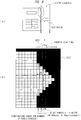
- FIG 1 is a perspective view illustrating an outline of a configuration example of an image reading device 100 according to an embodiment of the present invention.
- FIG. 2 is a block diagram illustrating an outline of the image reading device 100 according to the embodiment of the present invention.
- the image reading device 100 includes a suction port 110 through which a business form (a document used in a predetermined operation, for example, a bill or a check) is sucked, and a discharge port 120 through which the business form sucked in from the suction port 110 is discharged.
- a business form a document used in a predetermined operation, for example, a bill or a check
- the image reading device 100 is implemented as predetermined hardware or software.
- the image reading device 100 is configured of a computer including a processor, a memory, and the like, and a program recorded in the memory and executed by the processor causes the computer to function as the image reading device 100.
- the business form sucked through the suction port 110 is moved to the inside of the image reading device 100 by a transport roller (not illustrated), and is placed on a background section whose color is black. Then, the image of the business form is read in a state where the business form is placed on the background section. Thus, image data of the business form is obtained by a reading unit 130.
- the business form whose image data is obtained is transported by the transport roller to the outside of the image reading device 100 through the discharge port 120.
- the business form discharged through the discharge port 120 is accumulated on a stacker 121.
- the image reading device 100 includes the reading unit 130, a skew angle calculation unit 140, a circumscribed region detection unit 150, an image cutout unit 160, and an image storing unit 170.
- the reading unit 130 reads the image of the business form by scanning the business form placed on the background section whose color is black. Thus, the reading unit 130 obtains image data of the business form.
- the skew angle calculation unit 140 calculates a skew angle indicating the degree of inclination (inclination in the horizontal direction with respect to the background section) of the business form according to the image data of the image read by the reading unit 130.
- the skew angle calculation unit 140 inputs the calculated skew angle to the circumscribed region detection unit 150 and the image cutout unit 160.
- the circumscribed region detection unit 150 generates an image after a first skew correction (to be described later, FIG 5(a) ) obtained by rotating (correcting in a normal direction) the image read by the reading unit 130 according to the skew angle calculated by the skew angle calculation unit 140.
- the circumscribed region detection unit 150 scans the generated image after the first skew correction, and thus detects a circumscribed quadrangle circumscribed around the image of the business form and included in the image after the first skew correction.
- the circumscribed region detection unit 150 inputs coordinates of four corner points of the detected circumscribed quadrangle to the image cutout unit 160.
- the image cutout unit 160 cuts out the image of the business form (business-form image after cutout) from the image (business-form image) read by the reading unit 130 according to the coordinates of the four corner points of the circumscribed quadrangle detected by the circumscribed region detection unit 150.
- the image cutout unit 160 generates an image after a second skew correction obtained by rotating the cutout image of the business form (business-form image after cutout) according to the skew angle input by the skew angle calculation unit 140. Then, the image cutout unit 160 stores the generated image after the second skew correction in the image storing unit 170.
- FIGs. 3(a) and 3(b) are diagrams for explaining the reading method in the conventional image reading device.
- FIG 3(a) is a diagram for explaining a process of extracting end points of a business form 3000 by scanning the business form in longitudinal and lateral directions
- FIG. 3(b) is a diagram for explaining a process of extracting four corner points of the business form.
- the conventional image reading device scans the business form in the longitudinal direction and thus extracts an intersection between each scan line in the longitudinal direction and ends of the business form as an end point of the business form.
- the image reading device scans the business form in the lateral direction and thus extracts an intersection between each scan line in the lateral direction and ends of the business form as an end point of the business form.
- the image reading device extracts four edges by using the least-square method from the extracted end points of the business form, and extracts intersections of the extracted four edges as four corner points (P0 to P3) of the business form. Then, the image reading device cuts out the image of the business form according to the extracted four corner points (P0 to P3), and performs skew correction for the cutout image.
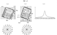
- FIGs. 4(a) to 4(c) are diagrams for explaining a process of calculating a skew angle of the image reading device 100 according to the embodiment of the present invention
- the reading unit 130 of the image reading device 100 scans a business form 400 in the lateral direction at predetermined intervals, and extracts intersections between scan lines 410 in the lateral direction and ends of the business form 400 as end points of the business form.
- the reading unit 130 extracts the location where the color of the scanned location changes from a background color to a business-form color (color other than the background color) as a first end point 411, and then extracts the location where the color of the scanned location changes from the business-form color to the background color as a second end point 412.
- the reading unit 130 scans the business form 400 in the lateral direction at predetermined intervals. Therefore, the reading unit 130 extracts the first end point 411 and the second end point 412 for each scanned location.
- the reading unit 130 inputs the extracted first end point 411 and second end point 412 into the skew angle calculation unit 140 every time the reading unit 130 extracts the first end point 411 and the second end point 412.
- the skew angle calculation unit 140 calculates the angle of the straight line connecting the coordinates of the first end point 411 previously input and the coordinates of the first end point 411 most recently input. In addition, the skew angle calculation unit 140 calculates the angle of the straight line connecting the coordinates of the second end point 412 previously input and the coordinates of the second end point 412 most recently input. Note that, in a case where the calculated angle is outside the range from 135° to 225° (equal to or greater than 135° and equal to or less than 225°), the skew angle calculation unit 140 performs correction such that the calculated angle falls within the range from 135° to 225° (12 to 20 in the figure) by adding one of the values 90°, 180°, and 270° to the calculated angle. Note that, in a case where the angle does not fall within the range from 135° to 225° even when one of the values 90°, 180°, and 270° are added to the calculated angle, the skew angle calculation unit 140 may abandon the calculated angle.
- the reading unit 130 of the image reading device 100 scans the business form 400 in the longitudinal direction at predetermined intervals, and extracts intersections between scan lines 420 in the longitudinal direction and ends of the business form 400 as end points of the business forms 400.
- the reading unit 130 extracts the location where the color of the scanned location changes from the background color to the business-form color (color other than the background color) as the first end point 411, and then extracts the location where the color of the scanned location changes from the business-form color to the background color as the second end point 412.
- the reading unit 130 scans the business form 400 in the longitudinal direction at predetermined intervals. Therefore, the reading unit 130 extracts the first end point 411 and the second end point 412 for each scanned location.
- the reading unit 130 inputs the extracted first end point 411 and second end point 412 into the skew angle calculation unit 140 every time the reading unit 130 extracts the first end point 411 and the second end point 412 at predetermined intervals.
- the skew angle calculation unit 140 calculates the angle of the straight line connecting the coordinates of the first end point 411 previously input and the coordinates of the first end point 411 most recently input. In addition, the skew angle calculation unit 140 calculates the angle of the straight line connecting the coordinates of the second end point 412 previously input and the coordinates of the second end point 412 most recently input. Note that, in a case where the calculated angle is outside the range from 135° to 225° (equal to or greater than 135° and equal to or less than 225°), the skew angle calculation unit 140 performs correction such that the calculated angle falls within the range from 135° to 225° by adding one of the values 90°, 180°, and 270° to the calculated angle. Note that, in a case where the angle does not fall within the range from 135° to 225° even when one of the values 90°, 180°, and 270° are added to the calculated angle, the skew angle calculation unit 140 may abandon the calculated angle.
- the skew angle calculation unit 140 counts the number of all the calculated angles (in a case where an angle is corrected, the angle after correction) for each angle. Then, the skew angle calculation unit 140 calculates the angle most frequently appearing as a result of counting, as the skew angle. Then, the skew angle calculation unit 140 inputs the calculated skew angle to the circumscribed region detection unit 150 and the image cutout unit 160.
- the skew angle calculation unit 140 calculates 202° as the skew angle.
- the skew angle calculation unit 140 may calculate the average value of all the calculated angles (in a case where an angle is corrected, the angle after correction) as the skew angle.
- the skew angle calculation unit 140 may calculate the median value of all the calculated angles (in a case where an angle is corrected, the angle after correction) as the skew angle.
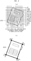
- the circumscribed region detection unit 150 generates an image 500 after the first skew correction illustrated in FIG. 5(a) by rotating the business-form image read by scanning the business form by the skew angle input from the skew angle calculation unit 140.
- the circumscribed region detection unit 150 scans the generated image 500 after the first skew correction and calculates p0 (xx0, yy0), which is coordinates of a corner point 501, p1 (xx1, yy1), which is coordinates of a corner point 502, p2 (xx2, yy2), which is coordinates of a corner point 503, and p3 (xx3, yy3), which is coordinates of a corner point 504, the corner points 501 to 504 being the four corner points of the circumscribed region in the image 500 after the first skew correction.
- a specific method of calculating the coordinates p0 to p3 of the four corner point 501 of the circumscribed region in the image 500 after the first skew correction by the circumscribed region detection unit 150 will be described later with reference to FIGs. 6 to 8 .
- the image cutout unit 160 converts the calculated coordinates p0 (xx0, yy0) to p3 (xx3, yy3) of the four corner points 501 to 504 of the circumscribed region in the image after the first skew correction into coordinates p0 (x0, y0) to p3 (x3, y3) of the four corner points of the circumscribed region in the business-form image.
- the image cutout unit 160 converts the coordinates p0 (xx0, yy0) into the coordinates p0 (x0, y0) by using the following formulae (1) and (2).
- p 0 x 0 X 0 + cos ⁇ ⁇ ⁇ xx 0 ⁇ sin ⁇ ⁇ ⁇ yy 0
- p 0 y 0 Y 0 + cos ⁇ ⁇ ⁇ yy 0 + sin ⁇ ⁇ ⁇ xx 0
- the image cutout unit 160 converts the coordinates p1 (xx1, yy1) into the coordinates p1 (x1, y1) by using the following formulae (3) and (4).
- p 1 x 1 X 0 + cos ⁇ ⁇ ⁇ xx 1 ⁇ sin ⁇ ⁇ ⁇ yy 1
- p 1 y 1 Y 0 + cos ⁇ ⁇ ⁇ yy 1 + sin ⁇ ⁇ ⁇ xx 1
- the image cutout unit 160 converts the coordinates p2 (xx2, yy2) into the coordinates p2 (x2, y2) by using the following formulae (5) and (6).
- p 2 x 2 X 0 + cos ⁇ ⁇ ⁇ xx 2 ⁇ sin ⁇ ⁇ ⁇ yy 2
- p 2 y 2 Y 0 + cos ⁇ ⁇ ⁇ yy 2 + sin ⁇ ⁇ ⁇ xx 2
- the image cutout unit 160 converts the coordinates p3 (xx3, yy3) into the coordinates p3 (x3, y3) by using the following formulae (7) and (8).
- p 3 x 3 X 0 + cos ⁇ ⁇ ⁇ xx 3 ⁇ sin ⁇ ⁇ ⁇ yy 3
- p 3 y 3 Y 0 + cos ⁇ ⁇ ⁇ yy 3 + sin ⁇ ⁇ ⁇ xx 3
- the image cutout unit 160 cuts out a business-form image after cutout from the business-form image according to the converted coordinates p0 (x0, y0) to p3 (x3, y3) of the four corner points of the circumscribed region in the business-form image and a parameter for specifying the cutout range of the business-form image after cutout from the business-form image. For example, there is a case where a range larger than a rectangle joining the coordinates p0 (x0, y0) to p3 (x3, y3) of the four corner points is specified as the cutout range of the business-form image after cutout according to a parameter.
- the image cutout unit 160 cuts out the business-form image after cutout into the size allowing the rectangle joining the coordinates p0 (x0, y0) to p3 (x3, y3) of the four corner points to be included with a predetermined (for example, 15-mm) margin around the outer periphery of the rectangle.
- the image cutout unit 160 generates an image after a second skew correction by rotating the business-form image after cutout by the skew angle. Then, the image cutout unit 160 stores the generated image after the second skew correction in the image storing unit 170.
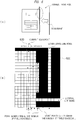
- FIG 6 is diagrams for explaining a process of detecting the circumscribed region of the business form without the possibility that the circumscribed region detection unit 150 according to the embodiment of the present invention erroneously recognizes lateral-line noise 601 in the lateral direction and longitudinal-line noise 602 in the longitudinal direction as a part of the business form.
- the circumscribed region detection unit 150 scans the image 500 after the first skew correction skew-corrected by being rotated by the skew angle in the lateral direction (for example, from right to left, or from left to right), then scans the image in the longitudinal direction (for example, from upper to lower or from lower to upper), and calculates the four corner points of the circumscribed region of the business-form image included in the image 500 after the first skew correction.
- the circumscribed region detection unit 150 detects the circumscribed region of the business-form image included in the image 500 after the first skew correction.
- the circumscribed region detection unit 150 scans the image after the first skew correction in the lateral direction.
- the circumscribed region detection unit 150 calculates the number of continuous pixels in the business form color (hereinafter, referred to as the number of continuous business form pixels, in some cases) included in the scanned range every time a scan line 620 extending in the longitudinal direction scans the image after the first skew correction by one column in the lateral direction (from right to left), and holds the calculated number of continuous business form pixels. Then, every time the circumscribed region detection unit 150 calculates the number of continuous business form pixels, the circumscribed region detection unit 150 determines whether or not the number of continuous business form pixels calculated for each scanning of most recent M (second value) times consecutively exceeds L (first value) M times.
- the circumscribed region detection unit 150 detects the location (X + 2 in the figure) scanned by the scan line 620 when the number of continuous business form pixels exceeds L at first as the circumscribed region of the business form (boundary between the business form and the background image).
- the lateral-line noise 601 in the lateral direction is less likely to be erroneously recognized as the business form by increasing the value of L.
- a longitudinal-line noise in the longitudinal direction (noise exceeding the value of L) is less likely to be erroneously recognized as the business form by increasing the value of M.
- the value of L is set to be smaller than the height (length in the longitudinal direction) of a tab.
- the border between the tab and the background image can be detected as the circumscribed region of the business form.
- the tab and the business form can be distinguished from each other.
- the value of L is set to be greater than the height of the tab, only the business form portion excluding the tab can be detected as the circumscribed region.
- the circumscribed region detection unit 150 calculates the number of continuous business form pixels included in the scanned range every time the scan line 620 in the longitudinal direction scans an image after the first skew correction by one column from right to left, and holds the calculated number of continuous business form pixels. Then, every time the circumscribed region detection unit 150 calculates the number of continuous business form pixels, the circumscribed region detection unit 150 determines whether or not the calculated number of continuous business form pixels exceeds L. Then, the circumscribed region detection unit 150 traces the numbers of continuous business form pixels calculated so far from the location where the number exceeds L (X in the figure) to the right (to the outside of the business form). Note that the circumscribed region detection unit 150 traces the numbers of continuous business form pixels on the assumption that the numbers will continuously decrease.
- the circumscribed region detection unit 150 detects the location (X + 3 in the figure) immediately before the location where the number of continuous business form pixels becomes 0 as the circumscribed region of the business form (boundary between the business form and the background image). Thus, the circumscribed region including the protruding part (comer part) of the protruding business form can be detected.
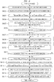
- FIG 9 is a diagram illustrating an outline of the entire process according to the embodiment of the present invention.
- the reading unit 130 sets an initial value (for example, 0) to the X coordinate for specifying the location of the column to be scanned in the longitudinal direction. In addition, the reading unit 130 sets an initial value (for example, 0) to the Y coordinate for specifying the location of the row to be scanned in the lateral direction.
- the reading unit 130 scans a business form in the longitudinal direction at the X coordinate set in S901, and thus extracts the intersections between the scan line in the longitudinal direction and the ends of the business form as end points of the business form and inputs the coordinates of the extracted end points to the skew angle calculation unit 140.
- the reading unit 130 extracts the location where the color of the scanned location changes from the background color to the business-form color (color other than the background color) as the first end point, and then, extracts the location where the color of the scanned location changes from the business-form color to the background color as the second end point. Then, the reading unit 130 inputs the coordinates of the extracted first and second end points to the skew angle calculation unit 140.
- the reading unit 130 determines the location to be scanned next.
- the reading unit 130 adds a predetermined value (for example, 1) to the X coordinate for specifying the location of the column to be scanned in the longitudinal direction.
- the reading unit 130 scans the business form in the longitudinal direction at the X coordinate obtained after the predetermined value is added in S903, and thus extracts the intersections between the scan line in the longitudinal direction and the ends of the business form as end points of the business form and inputs the coordinates of the extracted end points to the skew angle calculation unit 140.
- the reading unit 130 extracts the location where the color of the scanned location changes from the background color to the business-form color (color other than the background color) as the first end point, and then, extracts the location where the color of the scanned location changes from the business-form color to the background color as the second end point. Then, the reading unit 130 inputs the coordinates of the extracted first and second end points to the skew angle calculation unit 140.
- the skew angle calculation unit 140 calculates the angle of the straight line connecting the coordinates of the first end point previously input and the coordinates of the first end point most recently input. In addition, the skew angle calculation unit 140 calculates the angle of the straight line connecting the coordinates of the second end point input previously input and the coordinates of the second end point most recently input.
- the reading unit 130 determines whether or not scanning in the longitudinal direction has been all completed. In a case where the reading unit 130 determines that the scanning in the longitudinal direction has not been all completed (No in S906), the process returns to S903. In contrast, in a case where the reading unit 130 determines that the scanning in the longitudinal direction has been all completed (Yes in S906), the process proceeds to S907.
- the reading unit 130 scans the business form in the lateral direction at the Y coordinate set in S901, and thus extracts the intersections between the scan line in the lateral direction and the ends of the business form as end points of the business form and inputs the coordinates of the extracted end points to the skew angle calculation unit 140.
- the reading unit 130 extracts the location where the color of the scanned location changes from the background color to the business-form color (color other than the background color) as the first end point, and then, extracts the location where the color of the scanned location changes from the business-form color to the background color as the second end point. Then, the reading unit 130 inputs the coordinates of the extracted first and second end points to the skew angle calculation unit 140.
- the reading unit 130 determines the location to be scanned next.
- the reading unit 130 adds a predetermined value (for example, 1) to the Y coordinate for scanning in the lateral direction.
- the reading unit 130 scans the business form in the lateral direction at the Y coordinate obtained after the predetermined value is added in S908, and thus extracts the intersections between the scan line in the lateral direction and the ends of the business form as end points of the business form and inputs the coordinates of the extracted end points to the skew angle calculation unit 140.
- the skew angle calculation unit 140 calculates the angle of the straight line connecting the coordinates of the first end point input previously input and the coordinates of the first end point most recently input. In addition, the skew angle calculation unit 140 calculates the angle of the straight line connecting the coordinates of the second end point previously input and the coordinates of the second end point most recently input.
- the reading unit 130 determines whether or not the scanning in the lateral direction has been all completed. In a case where the reading unit 130 determines that the scanning in the lateral direction has not been all completed (No in S911), the process returns to S908. In contrast, in a case where the reading unit 130 determines that the scanning in the longitudinal direction has been all completed (Yes in S911), the process proceeds to S912.
- the skew angle calculation unit 140 calculates the skew angle according to all the angles calculated in S905 and all the angles calculated in S910.
- the skew angle calculation unit 140 inputs the calculated skew angle to the circumscribed region detection unit 150.
- the circumscribed region detection unit 150 generates an image after a first skew correction obtained by rotating the scanned and read business-form image by the skew angle input in S912.
- the circumscribed region detection unit 150 scans the image after the first skew correction generated in S913, and thus calculates the coordinates of the four corner points of the circumscribed region in the image after the first skew correction.
- the circumscribed region detection unit 150 inputs the calculated coordinates of the four corner points to the image cutout unit 160.
- the image cutout unit 160 converts the coordinates of the four corner points of the circumscribed region in the image after the first skew correction, the coordinates being calculated in S914, into the coordinates of the four corner points of the circumscribed region in the business-form image.
- the image cutout unit 160 cuts out a business-form image after cutout from the business-form image according to the coordinates of the four corner points of the circumscribed region in the business-form image, the coordinates being obtained as a result of conversion in S915 and a parameter for specifying the cutout range where the business-form image after cutout is cut.
- the image cutout unit 160 generates an image after a second skew correction by rotating the business-form image after cutout obtained as a result of cutout in S916 by the skew angle input in S912, and stores the generated image after the second skew correction in the image storing unit 170.
- the image cutout unit 160 cuts out the image of the business form from the image read by the reading unit 130 according to the coordinates of the four corner points of the circumscribed quadrangle, image data without a missing part can be obtained even in a case where the business form is not rectangular.
- the business forms can be collectively read.
- image data without a missing part can be stably obtained.
- image data of a rectangular image can be obtained.
- the circumscribed region detection unit 150 calculates the number of continuous pixels in the color other than black included in the scanned range. In a case where the calculated number of pixels consecutively exceeds the first value second-value times, the circumscribed region detection unit 150 detects the location scanned when the number of continuous pixels exceeds the first value at first as a side of the circumscribed quadrangle.
- a tab and a business form can be distinguished from each other by setting the first value to be smaller than the number of pixels in the longitudinal direction of the tab included in the business form
- the circumscribed region detection unit 150 calculates the number of continuous pixels in the color other than black included in the scanned range. In a case where the calculated number of pixels exceeds the first value, the circumscribed region detection unit 150 traces the numbers of pixels calculated so far, and detects the location immediately before the location where the number of pixels becomes 0 as a side of the circumscribed quadrangle. Thus, the image data of the protruding business form without a missing part can be obtained.
- 100 image reading device, 130 ... reading unit, 140 ... skew angle calculation unit, 150 ... circumscribed region detection unit, 160 ... image cutout unit, 170 ... image storing unit.
Description
- The present invention relates to an image reading device, an image reading method, and an image reading program.
- An image reading device such as an OCR (Optical Character Reader) or a scanner detects an end of a business form by using the fact that the background of the business form is black, detects four corner points of the business form, performs skew correction, extracts characteristic components, and thus obtains character recognition results and image data.
- When four corner points of a business form are detected and image data of the business form is acquired by using the above-described technique, there is a problem that only image data in which the image of a protruding portion (for example, a tab portion) is missing can be obtained in a case where the business form is not rectangular.
- Japanese Patent Application Laid-Open Publication No.
2010-171492 - Patent Document 1: Japanese Patent Application Laid-Open Publication No.
2010-171492 2 US 2013/182002 A andJP 2007 189577 A - With the technique disclosed in
Patent Document 1, even in a case where a business form is not rectangular, for example, in a case of a business form with a tab, image data in which a tab portion (protruding portion) is not missing can be obtained. However, in the technique disclosed inPatent Document 1, the tab portion is superimposed on the image of a business form main part. As a result, in the technique disclosed inPatent Document 1, a part of the image data of the business form main part is missing. - An object of the present invention is to provide a technique capable of obtaining image data without a missing part even in a case where a business form is not rectangular.
- The typical ones of the inventions disclosed in the present application will be briefly described as follows.
- According to an embodiment of the present invention, an image reading device including a reading unit which reads an image of a business form, the image reading device includes a skew angle calculation unit which calculates a skew angle used for correcting inclination of the business form according to image data of the image read by the reading unit, a circumscribed region detection unit which generates an image after a first skew correction obtained by rotating the image according to the skew angle, scans the generated image after the first skew correction, and thus detects a circumscribed quadrangle circumscribed around the image of the business form and included in the image after the first skew correction, and an image cutout unit which cuts out a business-form image after cutout from the image read by the reading unit, according to the circumscribed quadrangle.
- Also, according to the embodiment of the present invention, an image reading method in an image reading device including a reading unit that reads an image of a business form, the method includes a skew angle calculation step in which a skew angle calculation unit calculates a skew angle used for correcting inclination of the business form according to image data of the image read by the reading unit, a circumscribed region detection step in which a circumscribed region detection unit generates an image after a first skew correction obtained by rotating the image according to the skew angle, scans the generated image after the first skew correction, and thus detects a circumscribed quadrangle circumscribed around the image of the business form and included in the image after the first skew correction, and an image cutout step in which an image cutout unit cuts out a business-form image after cutout from the image read by the reading unit, according to the circumscribed quadrangle.
- Also, according to the embodiment of the present invention, an image reading program causing a computer of an image reading device including a reading unit that reads an image of a business form to execute a process, the process includes a skew angle calculation step in which a skew angle calculation unit calculates a skew angle used for correcting inclination of the business form according to image data of the image read by the reading unit, a circumscribed region detection step in which a circumscribed region detection unit generates an image after a first skew correction obtained by rotating the image according to the skew angle, scans the generated image after the first skew correction, and thus detects a circumscribed quadrangle circumscribed around the image of the business form and included in the image after the first skew correction, and an image cutout step in which an image cutout unit cuts out a business-form image after cutout from the image read by the reading unit, according to the circumscribed quadrangle.
- Effects obtained by the typical ones of the inventions disclosed in the present application will be briefly described as follows.
- According to a representative embodiment of the present invention, image data without a missing part can be obtained even in a case where a business form is not rectangular.
-
-
FIG 1 is a perspective view illustrating an outline of a configuration example of an image reading device according to an embodiment of the present invention; -
FIG 2 is a block diagram illustrating an outline of the image reading device according to the embodiment of the present invention; -
FIG 3(a) is a diagram for explaining a reading method in a conventional image reading device and for explaining a process of extracting end points of a business form by scanning the business form in longitudinal and lateral directions; -
FIG 3(b) is a diagram for explaining the reading method in the conventional image reading device and for explaining a process of extracting coordinates of four corner points of the business form; -
FIGs. 4(a) to 4(c) are diagrams for explaining a process of calculating a skew angle of the image reading device according to the embodiment of the present invention; -
FIG 5(a) is a diagram illustrating an example of an image after a first skew correction generated by a circumscribed region detection unit according to the embodiment of the present invention; -
FIG 5(b) is a diagram illustrating an example where an image cutout unit according to the embodiment of the present invention cuts out an image of a business form according to coordinates of four corner points of a circumscribed quadrangle; -
FIGs. 6(a) and 6(b) are diagrams for explaining a process where the circumscribed region detection unit according to the embodiment of the present invention detects a circumscribed region of the business form according the image after the first skew correction; -
FIGs. 7(a) and 7(b) are diagrams for explaining a process where the circumscribed region detection unit according to the embodiment of the present invention detects a circumscribed region of the business form according the image after the first skew correction; -
FIGs. 8(a) and 8(b) are diagrams for explaining a process where the circumscribed region detection unit according to the embodiment of the present invention detects a circumscribed region of the business form according the image after the first skew correction; and -
FIG 9 is a diagram illustrating an outline of the entire process according to the embodiment of the present invention. - Hereinafter, an embodiment of the present invention will be described in detail with reference to the accompanying drawings. Note that components having the same function are denoted by the same reference characters throughout the drawings for describing the embodiment, and the repetitive description thereof is omitted.
-
FIG 1 is a perspective view illustrating an outline of a configuration example of animage reading device 100 according to an embodiment of the present invention.FIG. 2 is a block diagram illustrating an outline of theimage reading device 100 according to the embodiment of the present invention. - As illustrated in
FIG. 1 , theimage reading device 100 includes asuction port 110 through which a business form (a document used in a predetermined operation, for example, a bill or a check) is sucked, and adischarge port 120 through which the business form sucked in from thesuction port 110 is discharged. - In addition, the
image reading device 100 is implemented as predetermined hardware or software. For example, theimage reading device 100 is configured of a computer including a processor, a memory, and the like, and a program recorded in the memory and executed by the processor causes the computer to function as theimage reading device 100. - The business form sucked through the
suction port 110 is moved to the inside of theimage reading device 100 by a transport roller (not illustrated), and is placed on a background section whose color is black. Then, the image of the business form is read in a state where the business form is placed on the background section. Thus, image data of the business form is obtained by areading unit 130. - The business form whose image data is obtained is transported by the transport roller to the outside of the
image reading device 100 through thedischarge port 120. The business form discharged through thedischarge port 120 is accumulated on astacker 121. - As illustrated in
FIG 2 , theimage reading device 100 includes thereading unit 130, a skewangle calculation unit 140, a circumscribedregion detection unit 150, animage cutout unit 160, and animage storing unit 170. - The
reading unit 130 reads the image of the business form by scanning the business form placed on the background section whose color is black. Thus, thereading unit 130 obtains image data of the business form. - The skew
angle calculation unit 140 calculates a skew angle indicating the degree of inclination (inclination in the horizontal direction with respect to the background section) of the business form according to the image data of the image read by thereading unit 130. The skewangle calculation unit 140 inputs the calculated skew angle to the circumscribedregion detection unit 150 and theimage cutout unit 160. - The circumscribed
region detection unit 150 generates an image after a first skew correction (to be described later,FIG 5(a) ) obtained by rotating (correcting in a normal direction) the image read by thereading unit 130 according to the skew angle calculated by the skewangle calculation unit 140. - In addition, the circumscribed
region detection unit 150 scans the generated image after the first skew correction, and thus detects a circumscribed quadrangle circumscribed around the image of the business form and included in the image after the first skew correction. The circumscribedregion detection unit 150 inputs coordinates of four corner points of the detected circumscribed quadrangle to theimage cutout unit 160. - The
image cutout unit 160 cuts out the image of the business form (business-form image after cutout) from the image (business-form image) read by thereading unit 130 according to the coordinates of the four corner points of the circumscribed quadrangle detected by the circumscribedregion detection unit 150. - In addition, the
image cutout unit 160 generates an image after a second skew correction obtained by rotating the cutout image of the business form (business-form image after cutout) according to the skew angle input by the skewangle calculation unit 140. Then, theimage cutout unit 160 stores the generated image after the second skew correction in theimage storing unit 170. -
FIGs. 3(a) and 3(b) are diagrams for explaining the reading method in the conventional image reading device.FIG 3(a) is a diagram for explaining a process of extracting end points of abusiness form 3000 by scanning the business form in longitudinal and lateral directions, andFIG. 3(b) is a diagram for explaining a process of extracting four corner points of the business form. - As illustrated in
FIG. 3(a) , the conventional image reading device scans the business form in the longitudinal direction and thus extracts an intersection between each scan line in the longitudinal direction and ends of the business form as an end point of the business form. In addition, the image reading device scans the business form in the lateral direction and thus extracts an intersection between each scan line in the lateral direction and ends of the business form as an end point of the business form. - Next, as illustrated in
FIG 3(b) , the image reading device extracts four edges by using the least-square method from the extracted end points of the business form, and extracts intersections of the extracted four edges as four corner points (P0 to P3) of the business form. Then, the image reading device cuts out the image of the business form according to the extracted four corner points (P0 to P3), and performs skew correction for the cutout image. - Here, in a case where four edges are extracted by using the least-square method, a side (straight line P1-P3) not including a tab is extracted as an edge even though the tab is actually included in the straight line P1-P3 portion. Then, in a case where the image of the business form is cut out according to the four corner points, which are intersections of the four edges, there is a problem that only image data where the image of a tab portion (protruding portion) is missing can be obtained.
-
FIGs. 4(a) to 4(c) are diagrams for explaining a process of calculating a skew angle of theimage reading device 100 according to the embodiment of the present invention - As illustrated in
FIG 4(a) , thereading unit 130 of theimage reading device 100 scans abusiness form 400 in the lateral direction at predetermined intervals, and extracts intersections betweenscan lines 410 in the lateral direction and ends of thebusiness form 400 as end points of the business form. - In detail, the
reading unit 130 extracts the location where the color of the scanned location changes from a background color to a business-form color (color other than the background color) as afirst end point 411, and then extracts the location where the color of the scanned location changes from the business-form color to the background color as asecond end point 412. Thereading unit 130 scans thebusiness form 400 in the lateral direction at predetermined intervals. Therefore, thereading unit 130 extracts thefirst end point 411 and thesecond end point 412 for each scanned location. - The
reading unit 130 inputs the extractedfirst end point 411 andsecond end point 412 into the skewangle calculation unit 140 every time thereading unit 130 extracts thefirst end point 411 and thesecond end point 412. - The skew
angle calculation unit 140 calculates the angle of the straight line connecting the coordinates of thefirst end point 411 previously input and the coordinates of thefirst end point 411 most recently input. In addition, the skewangle calculation unit 140 calculates the angle of the straight line connecting the coordinates of thesecond end point 412 previously input and the coordinates of thesecond end point 412 most recently input. Note that, in a case where the calculated angle is outside the range from 135° to 225° (equal to or greater than 135° and equal to or less than 225°), the skewangle calculation unit 140 performs correction such that the calculated angle falls within the range from 135° to 225° (12 to 20 in the figure) by adding one of the values 90°, 180°, and 270° to the calculated angle. Note that, in a case where the angle does not fall within the range from 135° to 225° even when one of the values 90°, 180°, and 270° are added to the calculated angle, the skewangle calculation unit 140 may abandon the calculated angle. - As illustrated in
FIG. 4(b) , thereading unit 130 of theimage reading device 100 scans thebusiness form 400 in the longitudinal direction at predetermined intervals, and extracts intersections betweenscan lines 420 in the longitudinal direction and ends of thebusiness form 400 as end points of the business forms 400. - In detail, the
reading unit 130 extracts the location where the color of the scanned location changes from the background color to the business-form color (color other than the background color) as thefirst end point 411, and then extracts the location where the color of the scanned location changes from the business-form color to the background color as thesecond end point 412. Thereading unit 130 scans thebusiness form 400 in the longitudinal direction at predetermined intervals. Therefore, thereading unit 130 extracts thefirst end point 411 and thesecond end point 412 for each scanned location. - The
reading unit 130 inputs the extractedfirst end point 411 andsecond end point 412 into the skewangle calculation unit 140 every time thereading unit 130 extracts thefirst end point 411 and thesecond end point 412 at predetermined intervals. - The skew
angle calculation unit 140 calculates the angle of the straight line connecting the coordinates of thefirst end point 411 previously input and the coordinates of thefirst end point 411 most recently input. In addition, the skewangle calculation unit 140 calculates the angle of the straight line connecting the coordinates of thesecond end point 412 previously input and the coordinates of thesecond end point 412 most recently input. Note that, in a case where the calculated angle is outside the range from 135° to 225° (equal to or greater than 135° and equal to or less than 225°), the skewangle calculation unit 140 performs correction such that the calculated angle falls within the range from 135° to 225° by adding one of the values 90°, 180°, and 270° to the calculated angle. Note that, in a case where the angle does not fall within the range from 135° to 225° even when one of the values 90°, 180°, and 270° are added to the calculated angle, the skewangle calculation unit 140 may abandon the calculated angle. - As illustrated in
FIG 4(c) , the skewangle calculation unit 140 counts the number of all the calculated angles (in a case where an angle is corrected, the angle after correction) for each angle. Then, the skewangle calculation unit 140 calculates the angle most frequently appearing as a result of counting, as the skew angle. Then, the skewangle calculation unit 140 inputs the calculated skew angle to the circumscribedregion detection unit 150 and theimage cutout unit 160. - In the example illustrated in
FIG 4(c) , the value 202° (18 in the figure) most frequently appears among the angles counted by the skewangle calculation unit 140. Therefore, the skewangle calculation unit 140 calculates 202° as the skew angle. Note that the skewangle calculation unit 140 may calculate the average value of all the calculated angles (in a case where an angle is corrected, the angle after correction) as the skew angle. In addition, the skewangle calculation unit 140 may calculate the median value of all the calculated angles (in a case where an angle is corrected, the angle after correction) as the skew angle. - The circumscribed
region detection unit 150 generates animage 500 after the first skew correction illustrated inFIG. 5(a) by rotating the business-form image read by scanning the business form by the skew angle input from the skewangle calculation unit 140. - Then, the circumscribed
region detection unit 150 scans the generatedimage 500 after the first skew correction and calculates p0 (xx0, yy0), which is coordinates of acorner point 501, p1 (xx1, yy1), which is coordinates of acorner point 502, p2 (xx2, yy2), which is coordinates of acorner point 503, and p3 (xx3, yy3), which is coordinates of acorner point 504, the corner points 501 to 504 being the four corner points of the circumscribed region in theimage 500 after the first skew correction. A specific method of calculating the coordinates p0 to p3 of the fourcorner point 501 of the circumscribed region in theimage 500 after the first skew correction by the circumscribedregion detection unit 150 will be described later with reference toFIGs. 6 to 8 . - Next, as illustrated in
FIG 5(b) , theimage cutout unit 160 converts the calculated coordinates p0 (xx0, yy0) to p3 (xx3, yy3) of the fourcorner points 501 to 504 of the circumscribed region in the image after the first skew correction into coordinates p0 (x0, y0) to p3 (x3, y3) of the four corner points of the circumscribed region in the business-form image. - In detail, the
image cutout unit 160 converts the coordinates p0 (xx0, yy0) into the coordinates p0 (x0, y0) by using the following formulae (1) and (2).

- In addition, the
image cutout unit 160 converts the coordinates p1 (xx1, yy1) into the coordinates p1 (x1, y1) by using the following formulae (3) and (4).

- In addition, the
image cutout unit 160 converts the coordinates p2 (xx2, yy2) into the coordinates p2 (x2, y2) by using the following formulae (5) and (6).

- In addition, the
image cutout unit 160 converts the coordinates p3 (xx3, yy3) into the coordinates p3 (x3, y3) by using the following formulae (7) and (8).

- The
image cutout unit 160 cuts out a business-form image after cutout from the business-form image according to the converted coordinates p0 (x0, y0) to p3 (x3, y3) of the four corner points of the circumscribed region in the business-form image and a parameter for specifying the cutout range of the business-form image after cutout from the business-form image. For example, there is a case where a range larger than a rectangle joining the coordinates p0 (x0, y0) to p3 (x3, y3) of the four corner points is specified as the cutout range of the business-form image after cutout according to a parameter. In that case, from the business-form image, theimage cutout unit 160 cuts out the business-form image after cutout into the size allowing the rectangle joining the coordinates p0 (x0, y0) to p3 (x3, y3) of the four corner points to be included with a predetermined (for example, 15-mm) margin around the outer periphery of the rectangle. - The
image cutout unit 160 generates an image after a second skew correction by rotating the business-form image after cutout by the skew angle. Then, theimage cutout unit 160 stores the generated image after the second skew correction in theimage storing unit 170. - Next, the specific method of calculating the coordinates p0 to p3 of the four
corner point 501 of the circumscribed region in the image after the first skew correction (described before,FIG 5(a) ) will be described with reference toFIGs. 6 to 8 . -
FIG 6 is diagrams for explaining a process of detecting the circumscribed region of the business form without the possibility that the circumscribedregion detection unit 150 according to the embodiment of the present invention erroneously recognizes lateral-line noise 601 in the lateral direction and longitudinal-line noise 602 in the longitudinal direction as a part of the business form. - The circumscribed
region detection unit 150 scans theimage 500 after the first skew correction skew-corrected by being rotated by the skew angle in the lateral direction (for example, from right to left, or from left to right), then scans the image in the longitudinal direction (for example, from upper to lower or from lower to upper), and calculates the four corner points of the circumscribed region of the business-form image included in theimage 500 after the first skew correction. Thus, the circumscribedregion detection unit 150 detects the circumscribed region of the business-form image included in theimage 500 after the first skew correction. - As illustrated in
FIG 6 , the circumscribedregion detection unit 150 scans the image after the first skew correction in the lateral direction. - The circumscribed
region detection unit 150 calculates the number of continuous pixels in the business form color (hereinafter, referred to as the number of continuous business form pixels, in some cases) included in the scanned range every time ascan line 620 extending in the longitudinal direction scans the image after the first skew correction by one column in the lateral direction (from right to left), and holds the calculated number of continuous business form pixels. Then, every time the circumscribedregion detection unit 150 calculates the number of continuous business form pixels, the circumscribedregion detection unit 150 determines whether or not the number of continuous business form pixels calculated for each scanning of most recent M (second value) times consecutively exceeds L (first value) M times. In a case where the calculated number of continuous business form pixels consecutively exceeds L (first value) M (second value) times, the circumscribedregion detection unit 150 detects the location (X + 2 in the figure) scanned by thescan line 620 when the number of continuous business form pixels exceeds L at first as the circumscribed region of the business form (boundary between the business form and the background image). - Note that the lateral-line noise 601 in the lateral direction is less likely to be erroneously recognized as the business form by increasing the value of L.
- In addition, a longitudinal-line noise in the longitudinal direction (noise exceeding the value of L) is less likely to be erroneously recognized as the business form by increasing the value of M.
- By detecting the circumscribed region of the business form (boundary between the business form and the background image) through the above-described method, resistance to the lateral-line noise 601 and the longitudinal-line noise 602 can be enhanced. In addition, even when a corner of the business form is arc-shaped, the circumscribed region of the business form can be stably detected.
- Note that, as illustrated in
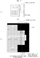
FIG 7 , in the case of detecting the edges of a tab-sheet business form, the value of L is set to be smaller than the height (length in the longitudinal direction) of a tab. Thus, the border between the tab and the background image can be detected as the circumscribed region of the business form. In addition, the tab and the business form can be distinguished from each other. In contrast, by setting the value of L to be greater than the height of the tab, only the business form portion excluding the tab can be detected as the circumscribed region. - Next, a process of detecting the edges of a business form a corner part of which is protruded since a part (comer part) of the business form is tapered toward the outside (hereinafter, referred to as a protruding business form, in some cases) will be described with reference to
FIG 8 . - First, the circumscribed
region detection unit 150 calculates the number of continuous business form pixels included in the scanned range every time thescan line 620 in the longitudinal direction scans an image after the first skew correction by one column from right to left, and holds the calculated number of continuous business form pixels. Then, every time the circumscribedregion detection unit 150 calculates the number of continuous business form pixels, the circumscribedregion detection unit 150 determines whether or not the calculated number of continuous business form pixels exceeds L. Then, the circumscribedregion detection unit 150 traces the numbers of continuous business form pixels calculated so far from the location where the number exceeds L (X in the figure) to the right (to the outside of the business form). Note that the circumscribedregion detection unit 150 traces the numbers of continuous business form pixels on the assumption that the numbers will continuously decrease. Then, the circumscribedregion detection unit 150 detects the location (X + 3 in the figure) immediately before the location where the number of continuous business form pixels becomes 0 as the circumscribed region of the business form (boundary between the business form and the background image). Thus, the circumscribed region including the protruding part (comer part) of the protruding business form can be detected. -
FIG 9 is a diagram illustrating an outline of the entire process according to the embodiment of the present invention. - First, in S901, the
reading unit 130 sets an initial value (for example, 0) to the X coordinate for specifying the location of the column to be scanned in the longitudinal direction. In addition, thereading unit 130 sets an initial value (for example, 0) to the Y coordinate for specifying the location of the row to be scanned in the lateral direction. - Next, in S902, the
reading unit 130 scans a business form in the longitudinal direction at the X coordinate set in S901, and thus extracts the intersections between the scan line in the longitudinal direction and the ends of the business form as end points of the business form and inputs the coordinates of the extracted end points to the skewangle calculation unit 140. - In detail, the
reading unit 130 extracts the location where the color of the scanned location changes from the background color to the business-form color (color other than the background color) as the first end point, and then, extracts the location where the color of the scanned location changes from the business-form color to the background color as the second end point. Then, thereading unit 130 inputs the coordinates of the extracted first and second end points to the skewangle calculation unit 140. - Next, in S903, the
reading unit 130 determines the location to be scanned next. In detail, thereading unit 130 adds a predetermined value (for example, 1) to the X coordinate for specifying the location of the column to be scanned in the longitudinal direction. - Next, in S904, the
reading unit 130 scans the business form in the longitudinal direction at the X coordinate obtained after the predetermined value is added in S903, and thus extracts the intersections between the scan line in the longitudinal direction and the ends of the business form as end points of the business form and inputs the coordinates of the extracted end points to the skewangle calculation unit 140. - In detail, the
reading unit 130 extracts the location where the color of the scanned location changes from the background color to the business-form color (color other than the background color) as the first end point, and then, extracts the location where the color of the scanned location changes from the business-form color to the background color as the second end point. Then, thereading unit 130 inputs the coordinates of the extracted first and second end points to the skewangle calculation unit 140. - Next, in S905, the skew
angle calculation unit 140 calculates the angle of the straight line connecting the coordinates of the first end point previously input and the coordinates of the first end point most recently input. In addition, the skewangle calculation unit 140 calculates the angle of the straight line connecting the coordinates of the second end point input previously input and the coordinates of the second end point most recently input. - Next, in S906, the
reading unit 130 determines whether or not scanning in the longitudinal direction has been all completed. In a case where thereading unit 130 determines that the scanning in the longitudinal direction has not been all completed (No in S906), the process returns to S903. In contrast, in a case where thereading unit 130 determines that the scanning in the longitudinal direction has been all completed (Yes in S906), the process proceeds to S907. - Next, in S907, the
reading unit 130 scans the business form in the lateral direction at the Y coordinate set in S901, and thus extracts the intersections between the scan line in the lateral direction and the ends of the business form as end points of the business form and inputs the coordinates of the extracted end points to the skewangle calculation unit 140. - In detail, the
reading unit 130 extracts the location where the color of the scanned location changes from the background color to the business-form color (color other than the background color) as the first end point, and then, extracts the location where the color of the scanned location changes from the business-form color to the background color as the second end point. Then, thereading unit 130 inputs the coordinates of the extracted first and second end points to the skewangle calculation unit 140. - Next, in S908, the
reading unit 130 determines the location to be scanned next. In detail, thereading unit 130 adds a predetermined value (for example, 1) to the Y coordinate for scanning in the lateral direction. - Next, in S909, the
reading unit 130 scans the business form in the lateral direction at the Y coordinate obtained after the predetermined value is added in S908, and thus extracts the intersections between the scan line in the lateral direction and the ends of the business form as end points of the business form and inputs the coordinates of the extracted end points to the skewangle calculation unit 140. - Next, in S910, the skew
angle calculation unit 140 calculates the angle of the straight line connecting the coordinates of the first end point input previously input and the coordinates of the first end point most recently input. In addition, the skewangle calculation unit 140 calculates the angle of the straight line connecting the coordinates of the second end point previously input and the coordinates of the second end point most recently input. - Next, in S911, the
reading unit 130 determines whether or not the scanning in the lateral direction has been all completed. In a case where thereading unit 130 determines that the scanning in the lateral direction has not been all completed (No in S911), the process returns to S908. In contrast, in a case where thereading unit 130 determines that the scanning in the longitudinal direction has been all completed (Yes in S911), the process proceeds to S912. - Next, in S912, the skew
angle calculation unit 140 calculates the skew angle according to all the angles calculated in S905 and all the angles calculated in S910. The skewangle calculation unit 140 inputs the calculated skew angle to the circumscribedregion detection unit 150. - Next, in S913, the circumscribed
region detection unit 150 generates an image after a first skew correction obtained by rotating the scanned and read business-form image by the skew angle input in S912. - Next, in S914, the circumscribed
region detection unit 150 scans the image after the first skew correction generated in S913, and thus calculates the coordinates of the four corner points of the circumscribed region in the image after the first skew correction. The circumscribedregion detection unit 150 inputs the calculated coordinates of the four corner points to theimage cutout unit 160. - Next, in S915, the
image cutout unit 160 converts the coordinates of the four corner points of the circumscribed region in the image after the first skew correction, the coordinates being calculated in S914, into the coordinates of the four corner points of the circumscribed region in the business-form image. - Next, in S916, the
image cutout unit 160 cuts out a business-form image after cutout from the business-form image according to the coordinates of the four corner points of the circumscribed region in the business-form image, the coordinates being obtained as a result of conversion in S915 and a parameter for specifying the cutout range where the business-form image after cutout is cut. - Next, in S917, the
image cutout unit 160 generates an image after a second skew correction by rotating the business-form image after cutout obtained as a result of cutout in S916 by the skew angle input in S912, and stores the generated image after the second skew correction in theimage storing unit 170. - According to the
image reading device 100 according to the above-described present embodiment, since theimage cutout unit 160 cuts out the image of the business form from the image read by thereading unit 130 according to the coordinates of the four corner points of the circumscribed quadrangle, image data without a missing part can be obtained even in a case where the business form is not rectangular. In addition, even if a business form with a protruding portion and a business form without a protruding portion are mixedly present, the business forms can be collectively read. Furthermore, even if the protruding amount or the protruding position varies, image data without a missing part can be stably obtained. Furthermore, image data of a rectangular image can be obtained. - In addition, every time the circumscribed
region detection unit 150 scans the image after the first skew correction, the circumscribedregion detection unit 150 calculates the number of continuous pixels in the color other than black included in the scanned range. In a case where the calculated number of pixels consecutively exceeds the first value second-value times, the circumscribedregion detection unit 150 detects the location scanned when the number of continuous pixels exceeds the first value at first as a side of the circumscribed quadrangle. Thus, it is possible to detect the circumscribed region of the business form without erroneously recognizing the lateral-line noise 601 in the lateral direction and the longitudinal-line noise 602 in the longitudinal direction as the business form - In addition, a tab and a business form can be distinguished from each other by setting the first value to be smaller than the number of pixels in the longitudinal direction of the tab included in the business form
- In addition, every time the circumscribed
region detection unit 150 scans the image after the first skew correction, the circumscribedregion detection unit 150 calculates the number of continuous pixels in the color other than black included in the scanned range. In a case where the calculated number of pixels exceeds the first value, the circumscribedregion detection unit 150 traces the numbers of pixels calculated so far, and detects the location immediately before the location where the number of pixels becomes 0 as a side of the circumscribed quadrangle. Thus, the image data of the protruding business form without a missing part can be obtained. - In the foregoing, the invention made by the inventors of the present invention has been concretely described based on the embodiment. However, it is needless to say that the present invention is not limited to the foregoing embodiment and various modifications and alterations can be made within the scope of the present invention.
- 100 ... image reading device, 130 ... reading unit, 140 ... skew angle calculation unit, 150 ... circumscribed region detection unit, 160 ... image cutout unit, 170 ... image storing unit.
Claims (6)
- An image reading device including a reading unit which reads an image of a business form by scanning the business form placed on a background section whose color is black, the image reading device comprising:a skew angle calculation unit which calculates a skew angle used for correcting inclination of the image of the business form according to image data of the image read by the reading unit;a circumscribed region detection unit which generates an image after a first skew correction obtained by rotating the image of the business form according to the skew angle, scans the generated image after the first skew correction, and thus detects a circumscribed quadrangle circumscribed around the image of the business form and included in the image after the first skew correction; andan image cutout unit which cuts out the business-form image after cutout from the image read by the reading unit, according to the circumscribed quadrangle;characterized in that every time the circumscribed region detection unit scans the image after the first skew correction, the circumscribed region detection unit calculates a number of continuous pixels in a color other than black included in a scanned range, and in a case where the calculated number of pixels consecutively exceeds a first value second-value times, the circumscribed region detection unit detects a location scanned when the number of continuous pixels exceeds the first value at first as a side of the circumscribed quadrangle.
- The image reading device according to claim 1,
wherein the image cutout unit generates an image after a second skew correction obtained by rotating the cutout image of the business form according to the skew angle, and stores the generated image after the second skew correction in an image storing unit. - The image reading device according to claim 1,
wherein the first value is smaller than the number of pixels in a longitudinal direction of a tab included in the business form. - The image reading device according to claim 1,
wherein every time the circumscribed region detection unit scans the image after the first skew correction, the circumscribed region detection unit calculates a number of continuous pixels in a color other than black included in a scanned range, and in a case where the calculated number of pixels exceeds a first value, the circumscribed region detection unit traces the numbers of pixels calculated so far, and detects a location immediately before a location where the number of pixels becomes 0 as a side of the circumscribed quadrangle. - An image reading method in an image reading device including a reading unit that reads an image of a business form by scanning the business form placed on a background section whose color is black, the method comprising:a skew angle calculation step in which a skew angle calculation unit calculates a skew angle used for correcting inclination of the image of the business form according to image data of the image read by the reading unit;a circumscribed region detection step in which a circumscribed region detection unit generates an image after a first skew correction obtained by rotating the image of the business form according to the skew angle, scans the generated image after the first skew correction, and thus detects a circumscribed quadrangle circumscribed around the image of the business form and included in the image after the first skew correction; andan image cutout step in which an image cutout unit cuts out a business-form image after cutout from the image read by the reading unit, according to the circumscribed quadrangle,characterized in that, in the circumscribed region detection step, every time the circumscribed region detection unit scans the image after the first skew correction, the circumscribed region detection unit calculates a number of continuous pixels in a color other than black included in a scanned range, and in a case where the calculated number of pixels consecutively exceeds a first value second-value times, the circumscribed region detection unit detects a location scanned when the number of continuous pixels exceeds the first value at first as a side of the circumscribed quadrangle.
- An image reading program causing a computer of an image reading device including a reading unit that reads an image of a business form by scanning the business form placed on a background section whose color is black to execute a process, the process including:a skew angle calculation step in which a skew angle calculation unit calculates a skew angle used for correcting inclination of the image of the business form according to image data of the image read by the reading unit;a circumscribed region detection step in which a circumscribed region detection unit generates an image after a first skew correction obtained by rotating the image of the business form according to the skew angle, scans the generated image after the first skew correction, and thus detects a circumscribed quadrangle circumscribed around the image of the business form and included in the image after the first skew correction; andan image cutout step in which an image cutout unit cuts out a business-form image after cutout from the image read by the reading unit, according to the circumscribed quadranglecharacterized in that, in the circumscribed region detection step, every time the circumscribed region detection unit scans the image after the first skew correction, the circumscribed region detection unit calculates a number of continuous pixels in a color other than black included in a scanned range, and in a case where the calculated number of pixels consecutively exceeds a first value second-value times, the circumscribed region detection unit detects a location scanned when the number of continuous pixels exceeds the first value at first as a side of the circumscribed quadrangle.
Applications Claiming Priority (1)
| Application Number | Priority Date | Filing Date | Title |
|---|---|---|---|
| PCT/JP2015/073813 WO2017033275A1 (en) | 2015-08-25 | 2015-08-25 | Image reading apparatus, image reading method, and image reading program |
Publications (3)
| Publication Number | Publication Date |
|---|---|
| EP3258681A1 EP3258681A1 (en) | 2017-12-20 |
| EP3258681A4 EP3258681A4 (en) | 2018-03-28 |
| EP3258681B1 true EP3258681B1 (en) | 2019-05-22 |
Family
ID=58099753
Family Applications (1)
| Application Number | Title | Priority Date | Filing Date |
|---|---|---|---|
| EP15899908.6A Active EP3258681B1 (en) | 2015-08-25 | 2015-08-25 | Image reading apparatus, image reading method, and image reading program |
Country Status (6)
| Country | Link |
|---|---|
| US (1) | US10091392B2 (en) |
| EP (1) | EP3258681B1 (en) |
| JP (1) | JP6383441B2 (en) |
| KR (1) | KR102001331B1 (en) |
| CN (1) | CN107211068B (en) |
| WO (1) | WO2017033275A1 (en) |
Families Citing this family (6)
| Publication number | Priority date | Publication date | Assignee | Title |
|---|---|---|---|---|
| JP6642833B2 (en) * | 2016-10-28 | 2020-02-12 | 京セラドキュメントソリューションズ株式会社 | Image processing device |
| CN107918935B (en) * | 2017-12-05 | 2022-03-08 | 深圳市北电仪表有限公司 | Image matching cutting device and cutting method of embedded system |
| JP7196474B2 (en) * | 2018-09-05 | 2022-12-27 | セイコーエプソン株式会社 | reader and program |
| JP2020052916A (en) * | 2018-09-28 | 2020-04-02 | 日本電産サンキョー株式会社 | Image processing device, image scanner, and image processing method |
| CN109409366B (en) * | 2018-10-30 | 2022-04-05 | 四川长虹电器股份有限公司 | Distorted image correction method and device based on angular point detection |
| US11532145B2 (en) * | 2019-01-07 | 2022-12-20 | Microsoft Technology Licensing, Llc | Multi-region image scanning |
Family Cites Families (13)
| Publication number | Priority date | Publication date | Assignee | Title |
|---|---|---|---|---|
| DE19858968A1 (en) * | 1998-01-14 | 1999-07-15 | Eastman Kodak Co | Identification of document angle on scanner bed |
| US6831755B1 (en) * | 1998-06-26 | 2004-12-14 | Sony Corporation | Printer having image correcting capability |
| JP2000081964A (en) * | 1998-06-26 | 2000-03-21 | Sony Corp | Printer device |
| JP2003209680A (en) * | 2002-01-15 | 2003-07-25 | Canon Inc | Image processing unit |
| JP3903932B2 (en) * | 2003-03-06 | 2007-04-11 | セイコーエプソン株式会社 | Image reading control device and program |
| JP2007189577A (en) * | 2006-01-16 | 2007-07-26 | Matsushita Electric Ind Co Ltd | Computer program, image input apparatus, image input system and image input method |
| JP4864653B2 (en) * | 2006-11-13 | 2012-02-01 | キヤノン電子株式会社 | Image reading apparatus, image reading method, and program for executing the method |
| JP2008259172A (en) * | 2007-03-15 | 2008-10-23 | Ricoh Co Ltd | Image processing device, image processing method, and program |
| JP5202037B2 (en) * | 2008-02-29 | 2013-06-05 | キヤノン株式会社 | Feature point position determination method and apparatus |
| JP2010171492A (en) | 2009-01-20 | 2010-08-05 | Konica Minolta Business Technologies Inc | Image processing apparatus, image processing method, and image processing program |
| CN101625760A (en) * | 2009-07-28 | 2010-01-13 | 谭洪舟 | Method for correcting certificate image inclination |
| US8989515B2 (en) * | 2012-01-12 | 2015-03-24 | Kofax, Inc. | Systems and methods for mobile image capture and processing |
| JP6070449B2 (en) * | 2013-07-08 | 2017-02-01 | 富士ゼロックス株式会社 | Inclination angle correction apparatus, image reading apparatus, image forming apparatus, and program |
-
2015
- 2015-08-25 JP JP2016574303A patent/JP6383441B2/en active Active
- 2015-08-25 CN CN201580075825.2A patent/CN107211068B/en active Active
- 2015-08-25 KR KR1020177033847A patent/KR102001331B1/en active IP Right Grant
- 2015-08-25 EP EP15899908.6A patent/EP3258681B1/en active Active
- 2015-08-25 WO PCT/JP2015/073813 patent/WO2017033275A1/en active Application Filing
- 2015-08-25 US US15/501,476 patent/US10091392B2/en active Active
Non-Patent Citations (1)
| Title |
|---|
| None * |
Also Published As
| Publication number | Publication date |
|---|---|
| KR102001331B1 (en) | 2019-07-17 |
| US20170237875A1 (en) | 2017-08-17 |
| CN107211068B (en) | 2019-05-03 |
| JPWO2017033275A1 (en) | 2017-08-31 |
| JP6383441B2 (en) | 2018-08-29 |
| EP3258681A1 (en) | 2017-12-20 |
| KR20170140313A (en) | 2017-12-20 |
| CN107211068A (en) | 2017-09-26 |
| US10091392B2 (en) | 2018-10-02 |
| EP3258681A4 (en) | 2018-03-28 |
| WO2017033275A1 (en) | 2017-03-02 |
Similar Documents
| Publication | Publication Date | Title |
|---|---|---|
| EP3258681B1 (en) | Image reading apparatus, image reading method, and image reading program | |
| US8194983B2 (en) | Method and system for preprocessing an image for optical character recognition | |
| US8559748B2 (en) | Edge detection | |
| US8218875B2 (en) | Method and system for preprocessing an image for optical character recognition | |
| US8139897B2 (en) | Detecting tilt in an image having different resolutions in different directions | |
| JP4574503B2 (en) | Image processing apparatus, image processing method, and program | |
| CN109089035B (en) | Image processing apparatus and image processing method | |
| JP2021043775A (en) | Information processing device and program | |
| US9894227B2 (en) | Information processing apparatus, information processing system, information processing method, and computer program product | |
| US7738696B2 (en) | Image processing apparatus and method for extracting a document area | |
| US10275888B2 (en) | Algorithmic method for detection of documents in images | |
| US11003902B2 (en) | Image identification apparatus and non-transitory computer readable medium | |
| JP4208520B2 (en) | Image processing apparatus, image processing method, program, and storage medium | |
| JP4167680B2 (en) | Document reading apparatus and document reading method | |
| US11328425B2 (en) | Image processing apparatus and non-transitory computer readable medium | |
| CN110097065B (en) | Freeman chain code-based line detection method and terminal | |
| JP6950237B2 (en) | Computer programs and image processing equipment | |
| US20120033889A1 (en) | Image determination apparatus, computer readable medium storing program, and method | |
| JP2010204806A (en) | Information processor, document processing system, and document processing method | |
| JP6743401B2 (en) | Form design/read setting support device, form design/read setting support method, and optical character recognition system | |
| JP5803643B2 (en) | Image processing apparatus, image processing method, and computer program | |
| JP6544124B2 (en) | Form identification device, form identification method and program | |
| JP2013152523A (en) | Document character difference detection device | |
| JP2021175051A (en) | Bend detection device, image processing device, and program | |
| EP2662802A1 (en) | Method and system for preprocessing an image for optical character recognition |
Legal Events
| Date | Code | Title | Description |
|---|---|---|---|
| STAA | Information on the status of an ep patent application or granted ep patent |
Free format text: STATUS: UNKNOWN |
|
| STAA | Information on the status of an ep patent application or granted ep patent |
Free format text: STATUS: THE INTERNATIONAL PUBLICATION HAS BEEN MADE |
|
| PUAI | Public reference made under article 153(3) epc to a published international application that has entered the european phase |
Free format text: ORIGINAL CODE: 0009012 |
|
| STAA | Information on the status of an ep patent application or granted ep patent |
Free format text: STATUS: REQUEST FOR EXAMINATION WAS MADE |
|
| 17P | Request for examination filed |
Effective date: 20170206 |
|
| AK | Designated contracting states |
Kind code of ref document: A1 Designated state(s): AL AT BE BG CH CY CZ DE DK EE ES FI FR GB GR HR HU IE IS IT LI LT LU LV MC MK MT NL NO PL PT RO RS SE SI SK SM TR |
|
| AX | Request for extension of the european patent |
Extension state: BA ME |
|
| STAA | Information on the status of an ep patent application or granted ep patent |
Free format text: STATUS: EXAMINATION IS IN PROGRESS |
|
| A4 | Supplementary search report drawn up and despatched |
Effective date: 20180227 |
|
| RIC1 | Information provided on ipc code assigned before grant |
Ipc: H04N 1/387 20060101AFI20180221BHEP Ipc: G06K 9/00 20060101ALI20180221BHEP Ipc: H04N 1/00 20060101ALI20180221BHEP |
|
| 17Q | First examination report despatched |
Effective date: 20180312 |
|
| DAV | Request for validation of the european patent (deleted) | ||
| DAX | Request for extension of the european patent (deleted) | ||
| GRAP | Despatch of communication of intention to grant a patent |
Free format text: ORIGINAL CODE: EPIDOSNIGR1 |
|
| STAA | Information on the status of an ep patent application or granted ep patent |
Free format text: STATUS: GRANT OF PATENT IS INTENDED |
|
| INTG | Intention to grant announced |
Effective date: 20190109 |
|
| GRAS | Grant fee paid |
Free format text: ORIGINAL CODE: EPIDOSNIGR3 |
|
| GRAA | (expected) grant |
Free format text: ORIGINAL CODE: 0009210 |
|
| STAA | Information on the status of an ep patent application or granted ep patent |
Free format text: STATUS: THE PATENT HAS BEEN GRANTED |
|
| AK | Designated contracting states |
Kind code of ref document: B1 Designated state(s): AL AT BE BG CH CY CZ DE DK EE ES FI FR GB GR HR HU IE IS IT LI LT LU LV MC MK MT NL NO PL PT RO RS SE SI SK SM TR |
|
| REG | Reference to a national code |
Ref country code: GB Ref legal event code: FG4D |
|
| REG | Reference to a national code |
Ref country code: CH Ref legal event code: EP |
|
| REG | Reference to a national code |
Ref country code: IE Ref legal event code: FG4D |
|
| REG | Reference to a national code |
Ref country code: DE Ref legal event code: R096 Ref document number: 602015031015 Country of ref document: DE |
|
| REG | Reference to a national code |
Ref country code: AT Ref legal event code: REF Ref document number: 1137501 Country of ref document: AT Kind code of ref document: T Effective date: 20190615 |
|
| REG | Reference to a national code |
Ref country code: NL Ref legal event code: MP Effective date: 20190522 |
|
| REG | Reference to a national code |
Ref country code: LT Ref legal event code: MG4D |
|
| PG25 | Lapsed in a contracting state [announced via postgrant information from national office to epo] |
Ref country code: NL Free format text: LAPSE BECAUSE OF FAILURE TO SUBMIT A TRANSLATION OF THE DESCRIPTION OR TO PAY THE FEE WITHIN THE PRESCRIBED TIME-LIMIT Effective date: 20190522 Ref country code: HR Free format text: LAPSE BECAUSE OF FAILURE TO SUBMIT A TRANSLATION OF THE DESCRIPTION OR TO PAY THE FEE WITHIN THE PRESCRIBED TIME-LIMIT Effective date: 20190522 Ref country code: LT Free format text: LAPSE BECAUSE OF FAILURE TO SUBMIT A TRANSLATION OF THE DESCRIPTION OR TO PAY THE FEE WITHIN THE PRESCRIBED TIME-LIMIT Effective date: 20190522 Ref country code: ES Free format text: LAPSE BECAUSE OF FAILURE TO SUBMIT A TRANSLATION OF THE DESCRIPTION OR TO PAY THE FEE WITHIN THE PRESCRIBED TIME-LIMIT Effective date: 20190522 Ref country code: AL Free format text: LAPSE BECAUSE OF FAILURE TO SUBMIT A TRANSLATION OF THE DESCRIPTION OR TO PAY THE FEE WITHIN THE PRESCRIBED TIME-LIMIT Effective date: 20190522 Ref country code: FI Free format text: LAPSE BECAUSE OF FAILURE TO SUBMIT A TRANSLATION OF THE DESCRIPTION OR TO PAY THE FEE WITHIN THE PRESCRIBED TIME-LIMIT Effective date: 20190522 Ref country code: SE Free format text: LAPSE BECAUSE OF FAILURE TO SUBMIT A TRANSLATION OF THE DESCRIPTION OR TO PAY THE FEE WITHIN THE PRESCRIBED TIME-LIMIT Effective date: 20190522 Ref country code: PT Free format text: LAPSE BECAUSE OF FAILURE TO SUBMIT A TRANSLATION OF THE DESCRIPTION OR TO PAY THE FEE WITHIN THE PRESCRIBED TIME-LIMIT Effective date: 20190922 Ref country code: NO Free format text: LAPSE BECAUSE OF FAILURE TO SUBMIT A TRANSLATION OF THE DESCRIPTION OR TO PAY THE FEE WITHIN THE PRESCRIBED TIME-LIMIT Effective date: 20190822 |
|
| PG25 | Lapsed in a contracting state [announced via postgrant information from national office to epo] |
Ref country code: LV Free format text: LAPSE BECAUSE OF FAILURE TO SUBMIT A TRANSLATION OF THE DESCRIPTION OR TO PAY THE FEE WITHIN THE PRESCRIBED TIME-LIMIT Effective date: 20190522 Ref country code: GR Free format text: LAPSE BECAUSE OF FAILURE TO SUBMIT A TRANSLATION OF THE DESCRIPTION OR TO PAY THE FEE WITHIN THE PRESCRIBED TIME-LIMIT Effective date: 20190823 Ref country code: RS Free format text: LAPSE BECAUSE OF FAILURE TO SUBMIT A TRANSLATION OF THE DESCRIPTION OR TO PAY THE FEE WITHIN THE PRESCRIBED TIME-LIMIT Effective date: 20190522 Ref country code: BG Free format text: LAPSE BECAUSE OF FAILURE TO SUBMIT A TRANSLATION OF THE DESCRIPTION OR TO PAY THE FEE WITHIN THE PRESCRIBED TIME-LIMIT Effective date: 20190822 |
|
| REG | Reference to a national code |
Ref country code: AT Ref legal event code: MK05 Ref document number: 1137501 Country of ref document: AT Kind code of ref document: T Effective date: 20190522 |
|
| PG25 | Lapsed in a contracting state [announced via postgrant information from national office to epo] |
Ref country code: CZ Free format text: LAPSE BECAUSE OF FAILURE TO SUBMIT A TRANSLATION OF THE DESCRIPTION OR TO PAY THE FEE WITHIN THE PRESCRIBED TIME-LIMIT Effective date: 20190522 Ref country code: RO Free format text: LAPSE BECAUSE OF FAILURE TO SUBMIT A TRANSLATION OF THE DESCRIPTION OR TO PAY THE FEE WITHIN THE PRESCRIBED TIME-LIMIT Effective date: 20190522 Ref country code: DK Free format text: LAPSE BECAUSE OF FAILURE TO SUBMIT A TRANSLATION OF THE DESCRIPTION OR TO PAY THE FEE WITHIN THE PRESCRIBED TIME-LIMIT Effective date: 20190522 Ref country code: AT Free format text: LAPSE BECAUSE OF FAILURE TO SUBMIT A TRANSLATION OF THE DESCRIPTION OR TO PAY THE FEE WITHIN THE PRESCRIBED TIME-LIMIT Effective date: 20190522 Ref country code: EE Free format text: LAPSE BECAUSE OF FAILURE TO SUBMIT A TRANSLATION OF THE DESCRIPTION OR TO PAY THE FEE WITHIN THE PRESCRIBED TIME-LIMIT Effective date: 20190522 Ref country code: SK Free format text: LAPSE BECAUSE OF FAILURE TO SUBMIT A TRANSLATION OF THE DESCRIPTION OR TO PAY THE FEE WITHIN THE PRESCRIBED TIME-LIMIT Effective date: 20190522 |
|
| REG | Reference to a national code |
Ref country code: DE Ref legal event code: R097 Ref document number: 602015031015 Country of ref document: DE |
|
| PG25 | Lapsed in a contracting state [announced via postgrant information from national office to epo] |
Ref country code: IT Free format text: LAPSE BECAUSE OF FAILURE TO SUBMIT A TRANSLATION OF THE DESCRIPTION OR TO PAY THE FEE WITHIN THE PRESCRIBED TIME-LIMIT Effective date: 20190522 Ref country code: SM Free format text: LAPSE BECAUSE OF FAILURE TO SUBMIT A TRANSLATION OF THE DESCRIPTION OR TO PAY THE FEE WITHIN THE PRESCRIBED TIME-LIMIT Effective date: 20190522 |
|
| PLBE | No opposition filed within time limit |
Free format text: ORIGINAL CODE: 0009261 |
|
| STAA | Information on the status of an ep patent application or granted ep patent |
Free format text: STATUS: NO OPPOSITION FILED WITHIN TIME LIMIT |
|
| PG25 | Lapsed in a contracting state [announced via postgrant information from national office to epo] |
Ref country code: TR Free format text: LAPSE BECAUSE OF FAILURE TO SUBMIT A TRANSLATION OF THE DESCRIPTION OR TO PAY THE FEE WITHIN THE PRESCRIBED TIME-LIMIT Effective date: 20190522 |
|
| 26N | No opposition filed |
Effective date: 20200225 |
|
| GBPC | Gb: european patent ceased through non-payment of renewal fee |
Effective date: 20190825 |
|
| PG25 | Lapsed in a contracting state [announced via postgrant information from national office to epo] |
Ref country code: PL Free format text: LAPSE BECAUSE OF FAILURE TO SUBMIT A TRANSLATION OF THE DESCRIPTION OR TO PAY THE FEE WITHIN THE PRESCRIBED TIME-LIMIT Effective date: 20190522 |
|
| PG25 | Lapsed in a contracting state [announced via postgrant information from national office to epo] |
Ref country code: SI Free format text: LAPSE BECAUSE OF FAILURE TO SUBMIT A TRANSLATION OF THE DESCRIPTION OR TO PAY THE FEE WITHIN THE PRESCRIBED TIME-LIMIT Effective date: 20190522 Ref country code: LU Free format text: LAPSE BECAUSE OF NON-PAYMENT OF DUE FEES Effective date: 20190825 Ref country code: MC Free format text: LAPSE BECAUSE OF FAILURE TO SUBMIT A TRANSLATION OF THE DESCRIPTION OR TO PAY THE FEE WITHIN THE PRESCRIBED TIME-LIMIT Effective date: 20190522 Ref country code: CH Free format text: LAPSE BECAUSE OF NON-PAYMENT OF DUE FEES Effective date: 20190831 Ref country code: LI Free format text: LAPSE BECAUSE OF NON-PAYMENT OF DUE FEES Effective date: 20190831 |
|
| REG | Reference to a national code |
Ref country code: BE Ref legal event code: MM Effective date: 20190831 |
|
| PG25 | Lapsed in a contracting state [announced via postgrant information from national office to epo] |
Ref country code: IE Free format text: LAPSE BECAUSE OF NON-PAYMENT OF DUE FEES Effective date: 20190825 Ref country code: FR Free format text: LAPSE BECAUSE OF NON-PAYMENT OF DUE FEES Effective date: 20190831 |
|
| PG25 | Lapsed in a contracting state [announced via postgrant information from national office to epo] |
Ref country code: BE Free format text: LAPSE BECAUSE OF NON-PAYMENT OF DUE FEES Effective date: 20190831 Ref country code: GB Free format text: LAPSE BECAUSE OF NON-PAYMENT OF DUE FEES Effective date: 20190825 |
|
| PG25 | Lapsed in a contracting state [announced via postgrant information from national office to epo] |
Ref country code: CY Free format text: LAPSE BECAUSE OF FAILURE TO SUBMIT A TRANSLATION OF THE DESCRIPTION OR TO PAY THE FEE WITHIN THE PRESCRIBED TIME-LIMIT Effective date: 20190522 |
|
| PG25 | Lapsed in a contracting state [announced via postgrant information from national office to epo] |
Ref country code: IS Free format text: LAPSE BECAUSE OF FAILURE TO SUBMIT A TRANSLATION OF THE DESCRIPTION OR TO PAY THE FEE WITHIN THE PRESCRIBED TIME-LIMIT Effective date: 20190922 |
|
| PG25 | Lapsed in a contracting state [announced via postgrant information from national office to epo] |
Ref country code: HU Free format text: LAPSE BECAUSE OF FAILURE TO SUBMIT A TRANSLATION OF THE DESCRIPTION OR TO PAY THE FEE WITHIN THE PRESCRIBED TIME-LIMIT; INVALID AB INITIO Effective date: 20150825 Ref country code: MT Free format text: LAPSE BECAUSE OF FAILURE TO SUBMIT A TRANSLATION OF THE DESCRIPTION OR TO PAY THE FEE WITHIN THE PRESCRIBED TIME-LIMIT Effective date: 20190522 |
|
| PG25 | Lapsed in a contracting state [announced via postgrant information from national office to epo] |
Ref country code: MK Free format text: LAPSE BECAUSE OF FAILURE TO SUBMIT A TRANSLATION OF THE DESCRIPTION OR TO PAY THE FEE WITHIN THE PRESCRIBED TIME-LIMIT Effective date: 20190522 |
|
| PGFP | Annual fee paid to national office [announced via postgrant information from national office to epo] |
Ref country code: DE Payment date: 20230821 Year of fee payment: 9 |