EP3258602B1 - Kapazitiver sensor - Google Patents
Kapazitiver sensor Download PDFInfo
- Publication number
- EP3258602B1 EP3258602B1 EP17176428.5A EP17176428A EP3258602B1 EP 3258602 B1 EP3258602 B1 EP 3258602B1 EP 17176428 A EP17176428 A EP 17176428A EP 3258602 B1 EP3258602 B1 EP 3258602B1
- Authority
- EP
- European Patent Office
- Prior art keywords
- sensor
- sensor electrode
- electrode
- switching position
- capacitive sensor
- Prior art date
- Legal status (The legal status is an assumption and is not a legal conclusion. Google has not performed a legal analysis and makes no representation as to the accuracy of the status listed.)
- Active
Links
Images
Classifications
-
- H—ELECTRICITY
- H03—ELECTRONIC CIRCUITRY
- H03K—PULSE TECHNIQUE
- H03K17/00—Electronic switching or gating, i.e. not by contact-making and –breaking
- H03K17/94—Electronic switching or gating, i.e. not by contact-making and –breaking characterised by the way in which the control signals are generated
- H03K17/965—Switches controlled by moving an element forming part of the switch
- H03K17/975—Switches controlled by moving an element forming part of the switch using a capacitive movable element
-
- H—ELECTRICITY
- H03—ELECTRONIC CIRCUITRY
- H03K—PULSE TECHNIQUE
- H03K17/00—Electronic switching or gating, i.e. not by contact-making and –breaking
- H03K17/94—Electronic switching or gating, i.e. not by contact-making and –breaking characterised by the way in which the control signals are generated
- H03K17/945—Proximity switches
- H03K17/955—Proximity switches using a capacitive detector
-
- H—ELECTRICITY
- H03—ELECTRONIC CIRCUITRY
- H03K—PULSE TECHNIQUE
- H03K2217/00—Indexing scheme related to electronic switching or gating, i.e. not by contact-making or -breaking covered by H03K17/00
- H03K2217/94—Indexing scheme related to electronic switching or gating, i.e. not by contact-making or -breaking covered by H03K17/00 characterised by the way in which the control signal is generated
- H03K2217/965—Switches controlled by moving an element forming part of the switch
- H03K2217/9651—Switches controlled by moving an element forming part of the switch the moving element acting on a force, e.g. pressure sensitive element
Definitions
- the invention relates to a capacitive sensor comprising a first sensor electrode and a second sensor electrode.
- the invention further relates to an associated gripping or clamping device, an associated handling unit and an associated method.
- Capacitive sensors are known from the state of the art in many different ways (see Wikipedia entry). Capacitive sensors work on the basis of the change in the capacitance of a single capacitor or an entire capacitor system. Capacitive sensors are based on two electrodes forming the "plates" of an electrical capacitor, whose capacitance or capacitance change is measured. Of course, the geometry of the two electrodes does not have to be plate-shaped, but can also have any other geometry. Capacitive sensors from the state of the art are from the WO 2011/130755 A2 , the US 2011/043227 A1 and the US 2013/076375 A1 known.
- a change in capacitance can occur on the one hand by changing the distance between the electrodes.
- a change in the plate distance d therefore results in a change in capacitance.
- This is therefore a capacitive pressure sensor in which a force is exerted on one of the plates so that the plate distance changes.
- a shielding electrode When using capacitive sensors as force or pressure sensors, a shielding electrode must be used regularly to detect only the process force, namely the force on one of the sensor electrodes, and to exclude external influences, in particular external electric fields. force to be measured due to external interference.
- either one of the sensor electrodes can be grounded, or an additional shield electrode is regularly used.
- both pressure sensors and proximity sensors are regularly required to operate such a system safely.
- the highest demands are placed on occupational safety in order to effectively prevent collisions between humans and robots or humans and the end effector of the robot.
- force sensors are required to measure the pressure force acting on a gripping or clamping device, for example.
- proximity sensors are required, for example to completely prevent a collision with an operator.
- two different capacitive sensors namely a force or pressure sensor and a proximity sensor, are required and are provided, for example, on a gripping or clamping device and/or on a handling device, such as a 6-axis robot. The provision of two sensors requires components, installation space and causes not inconsiderable costs.
- the invention is therefore based on the object of remedying these disadvantages of the prior art.
- the sensor has a first switching position in which the first sensor electrode and the second sensor electrode form a capacitor.
- the first sensor electrode is designed as a shield electrode.
- a change in the capacitance of the capacitor can be detected by a force that can be exerted on the first sensor electrode by means of an object touching the first sensor electrode. If a force is exerted by the object on the first sensor electrode, in particular if the object, for example a body part of an operator, presses on the first sensor electrode, the distance between the sensor electrodes changes, which results in a change in capacitance due to the capacitor formula. Consequently, a contact and the force of the contact can be detected.
- the invention provides that the sensor has a second switching position in which an electric field can be generated at the first sensor electrode in such a way that a change in capacitance can be detected when an object approaches the first sensor electrode.
- this second switching position there is of course still a first capacitor between the first sensor electrode and the second sensor electrode.
- the first sensor electrode no longer acts as a shielding electrode; instead, a voltage can be applied in such a way that electric field lines emerge from the first sensor electrode. These field lines strive to flow into the second sensor electrode. However, field lines spread out from the first sensor electrode which, for geometric reasons, have no direct path to the second sensor electrode.
- total capacitance capacitance of the first capacitor between the sensor electrodes + capacitance of the second capacitor between the first sensor electrode and the approaching object.
- the invention therefore results in a capacitive sensor that can be used both as a pressure or force sensor and as a proximity sensor, so that on the one hand a tactile sensor is present in the first switching position in which process forces acting on the element on which the capacitive sensor is arranged can be detected.
- a capacitive aura around the element on which the capacitive sensor is arranged can be measured by detecting an approaching object to the element without physical contact between the approaching object and the sensor.
- the first sensor electrode is grounded in the first switching position. This results in a particularly advantageous protective electrode that protects the capacitor between the first and second sensor electrodes from external influences.
- the second sensor electrode can be grounded in the second switching position.
- a further advantageous embodiment of the invention provides that a control device is provided which is designed to measure a change in capacitance and/or to apply a voltage to the sensor electrodes and/or to change the switching positions.
- control device is electrically connected to the first sensor electrode and the second sensor electrode, so that the control device can generate a voltage or a potential difference between the sensor electrodes.
- control device is also designed to measure the change in capacitance.
- an RC element or another known measuring method for measuring a change in capacitance can be used.
- the control device is also advantageously designed to change the switching positions.
- the control device is designed to initiate an action based on a measured change in capacitance.
- the action can, for example, consist of interrupting a movement of the element on which the capacitive sensor is arranged.
- the capacitive sensor can be provided on a gripping or clamping device and/or on a handling device, such as a robot, on which the gripping or clamping device is arranged. If a force acts on the first sensor electrode in the first switching position so that a change in capacitance is measured, the movement of the gripping or clamping device in space can be stopped or the direction of movement can be inverted. In the second switching position, a movement interruption or at least a Slowing down the movement in the direction of an approaching object so that a collision of the gripping or clamping device with the approaching object can be prevented or the force applied in the event of a collision can be reduced.
- the first sensor electrode is designed as a housing with a housing base and a housing shell, with the second sensor electrode being arranged inside the housing. This means that the capacitor can be protected from external influences in a particularly favorable manner in the first switching position.
- the housing can be pot-shaped or box-shaped, for example.
- the first sensor electrode can be designed to be flexible.
- the second sensor electrode is arranged on a non-conductive element, in particular a circuit board or a glass plate.
- a particularly preferred development of the invention results from the fact that the second sensor electrode is plate-shaped.
- the housing shell has a step on which the non-conductive element is arranged.
- a particularly simple capacitor can be provided by placing the non-conductive element directly on the step of the first sensor electrode and thus a capacitor is provided in which the non-conductive element acts as a dielectric between the two sensor electrodes. By providing it on the step, a spacing of the sensor electrodes from one another is also provided.
- This can either be filled with an elastically flexible dielectric or there can be air as a dielectric in the cavity.
- a changeover switch is provided for changing the switching positions, wherein the changeover switch can be controlled by cable or wirelessly.
- the control of the changeover switch can in particular be carried out by the control device.
- the first sensor electrode is preferably metallic.
- a metallic sensor electrode also allows elastic bending of the sensor electrode.
- the second sensor electrode can consist of copper or indium tin oxide (ITO) or comprise such a material.
- the dielectric constant of an object approaching in the second switching position is 1 to 10, in particular 2 to 8. This results in a significant and measurable change in the total capacitance of the capacitor system.
- the second capacitor between the object and the first sensor electrode consequently has a significant capacitance.
- An advantageous development of the invention provides that an RC element for measuring the change in capacitance A measurement using an RC element is possible in a particularly simple manner.
- the object set out at the beginning is also achieved by a gripping or clamping device with a sensor according to the invention arranged thereon. This allows, on the one hand, process forces acting on the gripping or clamping device to be measured in the first switching position. On the other hand, a collision of an object, in particular a body part of an operator, with the gripping or clamping device in the second switching position can be effectively prevented.
- a handling device in particular a robot, with a support arm and with a gripping or clamping device arranged or arrangeable on the support arm, wherein a sensor according to one of the preceding claims is provided on the support arm and/or on the gripping or clamping device.
- process forces can be measured in the first switching position.
- a collision of the handling device or the end effector designed as a gripping or clamping device can be effectively prevented, for example by slowing down or stopping the movement of the handling device towards the person or even inverting the direction of movement when a change in capacitance is measured as a result of a person approaching the handling device.
- the action can in particular consist in slowing down the movement of the end effector in space, interrupting it or inverting the direction of movement.
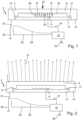
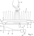
- the Figures 1 to 3 show a capacitive sensor, designated overall by the reference number 2.
- the capacitive sensor comprises a first sensor electrode 4 and a second sensor electrode 6 arranged at a distance therefrom and opposite.
- the first sensor electrode 4 is designed in the form of a housing with a plate-shaped housing base 8 and a housing side protruding therefrom, which represents a housing casing 10.
- the second sensor electrode 6 is also plate-shaped and made of copper and is arranged on a circuit board (circuit board) 12.
- the housing shell 10 of the first sensor electrode 4 has a step or shoulder 14.
- the circuit board 12 is arranged directly on this step.
- the capacitive sensor 2 also has a control device 16 designed as a microcontroller.
- the control device 16 is connected to the second sensor electrode 6 via an electrical conductor 18.
- the latter also has a ground connection 20.
- An electrical conductor 22 is also provided which connects the control device 16 to a changeover switch 24.
- the changeover switch 24 can be controlled between two switching positions either by cable or wirelessly, as indicated by the dashed line 26.
- the changeover switch 24 is switched so that the first sensor electrode 4 is grounded via the ground connection 20.
- the control device 16 By means of the control device 16, a voltage between the sensor electrodes 4, 6, with field lines running from the second sensor electrode 6 to the first sensor electrode 4, as indicated by the arrows 27.
- the two sensor electrodes 4, 6 consequently form a plate capacitor.
- the sensor electrodes are namely separated from one another by a cavity 28, with the air in the cavity acting as a dielectric.
- the grounded, first sensor electrode 4 is also the shielding electrode, with the second sensor electrode 6 being arranged completely within the volume enclosed by the first sensor electrode 4. Interfering external electric fields are therefore essentially completely shielded and cannot enter the volume enclosed by the first sensor electrode 4.
- a force F then acts on the housing base 8 of the first sensor electrode 4, as in Figure 1 indicated by the dashed line 30, the housing base is bent.
- the distance between the housing base 8 and the second sensor electrode 6 and thus the distance between the two sensor electrodes 4, 6 changes from an original distance d1 to a minimum distance d2 at the apex of the bent sensor electrode 4.
- This change in capacitance is detected by the control device 16, for example by means of an RC element.
- the capacitive sensor 2 is thus designed as a force sensor in the first switching position, which measures and detects a force on the sensor.
- the changeover switch 24 is switched by the control device 16 to the second switching position in which the sensor electrode 4 is connected to the Control device 16 is connected via the electrical conductor 22.
- the second sensor electrode 6 is grounded by means of the ground connection 20.
- the control device 16 then generates a voltage between the sensor electrodes 4, 6. Electric field lines thus emanate from the first sensor electrode 4, which now no longer acts as a shielding electrode.
- a second capacitor is formed between the first sensor electrode 4 and the approaching object 32.
- a second capacitance is formed between the first sensor electrode 4 and the object 32. This change in capacitance is detected by the control device 16.
- the present invention provides a capacitive sensor 2 which is designed as a force sensor in a first switching position, while it is designed as a proximity sensor in the second switching position.
- the capacitive sensor 2 can be used in particular on gripping or clamping devices that are arranged on a robot.
- process forces acting on the gripping or clamping device in the first switching position must be determined in some process steps.
- the approach of a person to the gripping or clamping device must be detected in order to prevent a collision. This means that a robot with an end effector can be operated safely in a human environment.
Landscapes
- Manipulator (AREA)
Description
- Die Erfindung betrifft einen kapazitiven Sensor, umfassend eine erste Sensorelektrode und eine zweite Sensorelektrode. Die Erfindung betrifft ferner eine dazugehörige Greif- bzw. Spannvorrichtung, eine dazugehörige Handhabungseinheit und ein dazugehöriges Verfahren.
- Kapazitive Sensoren sind aus dem Stand der Technik in vielfältiger Art und Weise vorbekannt (vgl. Wikipedia-Eintrag). Kapazitive Sensoren arbeiten dabei auf Basis der Veränderung der Kapazität eines einzelnen Kondensators oder eines ganzen Kondensatorsystems. Kapazitive Sensoren basieren darauf, dass zwei Elektroden die "Platten" eines elektrischen Kondensators bilden, dessen Kapazität bzw. Kapazitätsänderung gemessen wird. Selbstverständlich muss die Geometrie der beiden Elektroden nicht plattenförmig sein, sondern kann auch eine beliebige andere Geometrie aufweisen. Kapazitive Sensoren aus dem Stand der Technik sind aus der
WO 2011/130755 A2 , derUS 2011/043227 A1 und derUS 2013/076375 A1 bekannt. - Eine Kapazitätsänderung kann sich dabei einerseits dadurch ergeben, dass der Abstand der Elektroden zueinander geändert wird. Die elektrische Kapazität bestimmt sich dabei nach der Formel C = Q/U. In einem Plattenkondensator konkretisiert sich die Formel hierbei zu C = ε*A/d. Eine Änderung des Plattenabstands d resultiert folglich in einer Kapazitätsänderung. Hierbei handelt es sich folglich um einen kapazitiven Drucksensor, bei dem eine Kraft auf eine der Platten ausgeübt wird, so dass sich der Plattenabstand verändert.
- Andererseits ist auch denkbar, dass der Plattenabstand nicht verändert wird, sich jedoch die Kapazität dadurch ändert, dass ein elektrisch leitendes Material oder ein Dielektrikum in die unmittelbare Umgebung einer der Sensorelektroden gebracht wird. Diese sog. Abstands- bzw. Näherungssensoren basieren darauf, dass sich das annähernde Objekt mit einer der beiden Sensorelektroden einen weiteren elektrischen Kondensator ausbildet, wobei sich die Gesamtkapazität des Systems ändert, indem gilt totale Kapazität = Kapazität des Kondensators zwischen den beiden Sensorelektroden + Kapazität des neu ausgebildeten Kondensators.
- Bei der Verwendung von kapazitiven Sensoren als Kraft- bzw. Drucksensoren muss regelmäßig eine Schirmelektrode eingesetzt werden, um lediglich die Prozesskraft, nämlich die Kraft auf eine der Sensorelektroden zu detektieren und äußere Einflüsse, insbesondere externe elektrische Felder, zu messenden Kraft durch äußere Störungen. Hierzu kann entweder eine der Sensorelektroden geerdet sein, oder es wird regelmäßig eine zusätzliche Schirmelektrode eingesetzt.
- Bei Anwendungen, beispielsweise in der Handhabungstechnik, insbesondere beim Einsatz von Greif- bzw. Spannvorrichtungen an Handhabungseinrichtungen, werden regelmäßig sowohl Drucksensoren als auch Näherungssensoren zum sicheren Betreiben eines derartigen Systems benötigt. Insbesondere bei der Mensch-Roboter-Kollaboration werden höchste Anforderungen an die Arbeitssicherheit gestellt, um Kollisionen zwischen Mensch und Roboter bzw. Mensch und Endeffektor des Roboters wirksam zu verhindern. Für gewisse Anwendungen werden hierbei Kraftsensoren zur Messung der auf beispielsweise eine Greif- bzw. Spannvorrichtung einwirkenden Druckkraft benötigt. Für andere Anwendungen werden hingegen Näherungssensoren benötigt, beispielsweise um eine Kollision mit einer Bedienperson vollständig zu verhindern. Insofern werden zwei unterschiedliche kapazitive Sensoren, nämlich ein Kraft bzw. Drucksensor und ein Näherungssensor benötigt und beispielsweise an einer Greif- bzw. Spannvorrichtung und/oder an einer Handhabungseinrichtung, wie beispielsweise einem 6-Achs-Roboter, vorgesehen. Das Vorsehen von zwei Sensoren benötigt zum einen Bauteile, Bauraum und verursacht nicht unerhebliche Kosten.
- Der Erfindung liegt daher die Aufgabe zugrunde, diesen Nachteilen des Standes der Technik Abhilfe zu schaffen.
- Diese Aufgabe wird durch einen kapazitiven Sensor mit den Merkmalen des Anspruchs 1 gelöst.
- Es ist demnach vorgesehen, dass der Sensor eine erste Schaltstellung aufweist, in der die erste Sensorelektrode und die zweite Sensorelektrode einen Kondensator bilden. Hierbei ist die erste Sensorelektrode als Schirmelektrode ausgebildet. Dabei kann eine Kapazitätsänderung des Kondensators durch eine auf die erste Sensorelektrode ausübbare Kraft mittels eines die erste Sensorelektrode berührenden Objekts detektiert werden. Wird eine Kraft durch das Objekt auf die erste Sensorelektrode ausgeübt, insbesondere indem das Objekt, beispielsweise ein Körperteil einer Bedienperson auf die erste Sensorelektrode drückt, so ändert sich der Abstand der Sensorelektroden zueinander, was auf Grund der Kondensatorformel in einer Kapazitätänderung resultiert. Es kann folglich eine Berührung und die Kraft der Berührung detektiert werden.
- Ferner ist erfindungsgemäß vorgesehen, dass der Sensor eine zweite Schaltstellung aufweist, in der an der ersten Sensorelektrode ein elektrisches Feld derart erzeugbar ist, dass durch Annäherung eines Objekts an die erste Sensorelektrode eine Kapazitätsänderung detektierbar ist. In dieser zweiten Schaltstellung ist selbstverständlich immer noch ein erster Kondensator zwischen der ersten Sensorelektrode und der zweiten Sensorelektrode vorhanden. Allerdings wirkt die erste Sensorelektrode nun nicht mehr als Schirmelektrode, stattdessen ist eine Spannung derart anlegbar, dass elektrische Feldlinien aus der ersten Sensorelektrode austreten. Diese Feldlinien haben das Bestreben, in die zweite Sensorelektrode zu münden. Allerdings streuen Feldlinien aus der ersten Sensorelektrode aus, die geometrisch bedingt keinen direkten Weg zur zweiten Sensorelektrode haben. Nähert sich nun ein Objekt ohne physikalischen Kontakt mit der ersten Sensorelektrode an die erste Sensorelektrode, so bündeln sich die streuenden Feldlinien bzw. ein Teil der streuenden Feldlinien in dem sich nähernden Objekt, was zu einer detektierbaren Kapazitätsänderung führt, indem zwischen dem sich nähernden Objekt und der ersten Sensorelektrode ein zusätzlicher Kondensator ausgebildet wird. Die gemessene Gesamtkapazität vergrößert sich folglich, indem gilt, totale Kapazität = Kapazität des ersten Kondensators zwischen den Sensorleketroden + Kapazität des zweiten Kondensators zwischen erste Sensorelektrode und sich näherndem Objekt.
- Insgesamt ergibt sich erfindungsgemäß folglich ein kapazitiver Sensor, der sowohl als Druck- bzw. Kraftsensor als auch als Näherungssensor einsetzbar ist, so dass zum einen eine taktile Sensorik in der ersten Schaltstellung vorhanden ist, in der Prozesskräfte erfassbar sind, die auf das Element wirken, an dem der kapazitive Sensor angeordnet ist. In der zweiten Schaltstellung kann hingegen eine kapazitive Aura um das Element, an dem der kapazitive Sensor angeordnet ist, gemessen werden, indem ein sich näherndes Objekt an das Element ohne physikalischen Kontakt zwischen dem sich nähernden Objekt und dem Sensor detektiert wird.
- Vorzugsweise ist die erste Sensorelektrode in der ersten Schaltstellung geerdet. Hierdurch ergibt sich eine besonders vorteilhaft wirkende Schutzelektrode, die den Kondensator zwischen erster und zweiter Sensorelektrode vor äußeren Einflüssen schützt.
- Zusätzlich oder alternativ kann in der zweiten Schaltstellung die zweite Sensorelektrode geerdet sein.
- Eine weitere vorteilhafte Ausgestaltung der Erfindung sieht vor, dass eine Steuereinrichtung vorgesehen ist, die zum Messen einer Kapazitätsänderung und/oder zum Anlegen einer Spannung an die Sensorelektroden und/oder zum Wechseln der Schaltstellungen ausgebildet ist.
- Vorteilhafterweise ist die Steuereinrichtung elektrisch mit der ersten Sensorelektrode und der zweiten Sensorelektrode verbunden, so dass die Steuereinrichtung eine Spannung bzw. eine Potentialdifferenz zwischen den Sensorelektroden erzeugen kann. Günstigerweise ist die Steuereinrichtung zudem zur Messung der Kapazitätsänderung ausgebildet. Hierzu kann beispielsweise ein RC-Glied oder eine andere bekannte Messmethode zur Messung einer Kapazitätsänderung Verwendung finden. Schließlich ist vorteilhafterweise die Steuereinrichtung zudem zum Wechseln der Schaltstellungen ausgebildet.
- Vorteilhaft ist auch, wenn die Steuereinrichtung zur Veranlassung einer Aktion basierend auf einer gemessenen Kapazitätsänderung ausgebildet ist. Die Aktion kann beispielsweise darin bestehen, eine Bewegung des Elements, an dem der kapazitive Sensor angeordnet ist, zu unterbrechen. Beispielsweise kann der kapazitive Sensor an einer Greif- bzw. Spannvorrichtung und/oder an einer Handhabungseinrichtung, wie beispielsweise einem Roboter, an dem die Greif- bzw. Spannvorrichtung angeordnet ist, vorgesehen sein. Wirkt in der ersten Schaltstellung eine Kraft auf die erste Sensorelektrode, so dass eine Kapazitätsänderung gemessen wird, so kann folglich die Bewegung der Greif- bzw. Spannvorrichtung im Raum gestoppt werden bzw. eine Bewegungsrichtungsinvertierung durchgeführt werden. In der zweiten Schaltstellung kann ebenfalls eine Bewegungsunterbrechung oder zumindest ein Verlangsamen der Bewegung in Richtung eines sich nähernden Objekts veranlasst werden, so dass eine Kollision der Greif- bzw. Spannvorrichtung mit dem sich nähernden Objekt verhindert werden kann bzw. die Krafteinwirkung im Kollisionsfall reduziert werden kann.
- Die erste Sensorelektrode ist als Gehäuse mit einem Gehäuseboden und einem Gehäusemantel ausgebildet, wobei die zweite Sensorelektrode innerhalb des Gehäuses angeordnet ist. Somit kann der Kondensator in der ersten Schaltstellung in besonders günstiger Weise vor äußeren Einflüssen geschützt werden. Das Gehäuse kann dabei beispielsweise topfförmig oder auch kastenförmig ausgebildet sein.
- Besonders bevorzugt ist, wenn eine Kraft auf die erste Sensorelektrode in der ersten Schaltstellung ein Durchbiegen des Gehäusebodens und damit eine Abstandsänderung der Sensorelektroden bewirkt, was eine Kapazitätsänderung induziert. Hierzu kann die erste Sensorelektrode biegbar ausgebildet sein.
- Die zweite Sensorelektrode ist auf einem nicht-leitenden Element, insbesondere einer Leiterplatte oder einer Glasplatte, angeordnet.
- Eine besonders bevorzugte Weiterbildung der Erfindung ergibt sich daraus, dass die zweite Sensorelektrode plattenförmig ausgebildet ist.
- In diesem Zusammenhang ist vorgesehen, dass der Gehäusemantel eine Stufe aufweist, an der das nicht-leitende Element angeordnet ist. Insofern kann ein besonders einfach aufgebauter Kondensator bereitgestellt werden, indem das nicht leitende Element unmittelbar an der Stufe der ersten Sensorelektrode anliegt und somit ein Kondensator bereitgestellt wird, in dem das nicht leitende Element als Dielektrikum zwischen den beiden Sensorelektroden wirkt. Durch das Vorsehen an der Stufe wird zudem eine Beabstandung der Sensorelektroden zueinander bereitgestellt.
- Zwischen den beiden Sensorelektroden selbst kann insbesondere ein Hohlraum vorhanden sein. Dieser kann entweder durch ein elastisch nachgiebiges Dielektrikum ausgefüllt sein oder aber es kann Luft als Dielektrikum im Hohlraum vorhanden sein.
- Besonders bevorzugt ist, wenn ein Wechselschalter zum Wechseln der Schaltstellungen vorgesehen ist, wobei der Wechselschalter kabelgebunden oder kabellos steuerbar ist. Die Ansteuerung des Wechselschalters kann hierbei insbesondere durch die Steuereinrichtung erfolgen.
- Vorzugsweise ist dabei die erste Sensorelektrode metallisch. Eine metallische Sensorelektrode erlaubt insbesondere auch ein elastisches Durchbiegen der Sensorelektrode. Zusätzlich oder alternativ kann die zweite Sensorelektrode aus Kupfer oder Indiumzinnoxid (ITO) bestehen oder ein solches Material umfassen.
- Besonders bevorzugt ist, wenn die Dielektrizitätszahl eines sich in der zweiten Schaltstellung annähernden Objekts 1 bis 10, insbesondere 2 bis 8, beträgt. Hierdurch ergibt sich eine signifikante und messbare Änderung der Gesamtkapazität des Kondensatorsystems. Insbesondere weist der zweite Kondensator zwischen Objekt und erster Sensorelektrode folglich eine signifikante Kapazität auf.
- Eine vorteilhafte Weiterbildung der Erfindung sieht vor, dass ein RC-Glied zum Messen der Kapazitätsänderung vorgesehen ist. Eine Messung mittels eines RC-Glieds ist auf besonders einfache Art und Weise möglich.
- Die eingangs gestellte Aufgabe wird auch durch eine Greif- oder Spannvorrichtung mit einem daran angeordneten, erfindungsgemäßen Sensor gelöst. Damit können zum einen in der ersten Schaltstellung auf die Greif- oder Spannvorrichtung wirkende Prozesskräfte gemessen werden. Zum anderen kann eine Kollision eines Objekts, insbesondere eines Körperteils einer Bedienperson, mit der Greif- oder Spannvorrichtung in der zweiten Schaltstellung wirksam verhindert werden.
- Ferner wird die eingangs gestellte Aufgabe auch gelöst durch eine Handhabungseinrichtung, insbesondere einen Roboter, mit einem Trägerarm und mit einer am Trägerarm angeordneten oder anordenbaren Greif- oder Spannvorrichtung, wobei ein Sensor nach einem der vorhergehenden Ansprüche am Trägerarm und/oder an der Greif- oder Spannvorrichtung vorgesehen ist. Auch hier können in der ersten Schaltstellung Prozesskräfte gemessen werden. In der zweiten Schaltstellung kann eine Kollision der Handhabungseinrichtung bzw. des als Greif- oder Spannvorrichtung ausgebildeten Endeffektors wirksam verhindert werden, indem beispielsweise bei gemessener Kapazitätsänderung durch Annäherung einer Person an die Handhabungseinrichtung, die Bewegung der Handhabungseinrichtung auf die Person verlangsamt oder angehalten wird oder sogar eine Bewegungsrichtungsinvertierung durchgeführt wird.
- Schließlich wird die eingangs genannte Aufgabe auch gelöst durch ein Verfahren zum Betreiben eines erfindungsgemäßen Sensors, wobei eine Steuereinrichtung zur Veranlassung einer Aktion basierend auf einer vom Sensor gemessenen Kapazitätsänderung vorgesehen ist, umfassend die folgenden Schritte:
- a. Messen der Kapazität mittels der Steuereinrichtung in der ersten Schaltstellung und/oder der zweiten Schaltstellung;
- b. Veranlassen einer Aktion, wenn die in der ersten Schaltstellung und/oder der zweiten Schaltstellung gemessene Kapazitätsänderung einen Grenzwert überschreitet.
- Ist der Sensor beispielsweise an einem Endeffektor einer Handhabungseinrichtung, insbesondere einem Roboter, angeordnet, so kann die Aktion insbesondere darin bestehen, die Bewegung des Endeffektors im Raum zu verlangsamen, zu unterbrechen oder die Bewegungsrichtung zu invertieren.
- Weitere Einzelheiten und vorteilhafte Ausgestaltungen der Erfindung sind der folgenden Beschreibung zu entnehmen, anhand derer die in den Figuren dargestellte Ausführungsform der Erfindung näher beschrieben und erläutert ist. Es zeigen:
- Figur 1
- eine schematische Darstellung eines kapazitiven Sensors in einer ersten Schaltstellung;
- Figur 2
- eine schematische Darstellung des kapazitiven Sensors gemäß
Figur 1 in einer zweiten Schaltstellung; und - Figur 3
- Darstellung gemäß
Figur 2 , wobei sich ein Objekt an die erste Sensorelektrode annähert. - Die
Figuren 1 bis 3 zeigen einen insgesamt mit dem Bezugszeichen 2 bezeichneten kapazitiven Sensor. Der kapazitive Sensor umfasst dabei eine erste Sensorelektrode 4 und eine zweite dazu beabstandet und gegenüberliegend angeordnete Sensorelektrode 6. Die erste Sensorelektrode 4 ist dabei gehäuseförmig mit einem plattenförmigen Gehäuseboden 8 und einer davon abragenden Gehäuseseite, die einen Gehäusemantel 10 darstellt, ausgebildet. - Die zweite Sensorelektrode 6 ist ebenfalls plattenförmig und aus Kupfer bestehend ausgebildet und an einer Leiterplatte (Platine) 12 angeordnet. Der Gehäusemantel 10 der ersten Sensorelektrode 4 weist eine Stufe bzw. Schulter 14 auf. An dieser Stufe ist die Leiterplatte 12 unmittelbar angeordnet.
- Der kapazitive Sensor 2 weist ferner eine als Microcontroller ausgebildete Steuereinrichtung 16 auf. Die Steuereinrichtung 16 ist dabei zum einen über einen elektrischen Leiter 18 mit der zweiten Sensorelektrode 6 verbunden. Zum anderen weist diese einen Erdungsanschluss 20 auf. Ferner ist ein elektrischer Leiter 22 vorgesehen, der die Steuereinrichtung 16 mit einem Wechselschalter 24 verbindet. Der Wechselschalter 24 ist dabei, wie mit der gestrichelten Linie 26 angedeutet, kabelgebunden oder kabellos zwischen zwei Schaltstellungen steuerbar.
- Die Funktionsweise des kapazitiven Sensors 2 ist sodann wie folgt:
In der inFigur 1 gezeigten ersten Schaltstellung ist der Wechselschalter 24 so geschaltet, dass die erste Sensorelektrode 4 über den Erdungsanschluss 20 geerdet ist. Mittels der Steuereinrichtung 16 wird sodann eine Spannung zwischen den Sensorelektroden 4, 6 erzeugt, wobei Feldlinien, wie mit den Pfeilen 27 angedeutet, von der zweiten Sensorelektrode 6 zur ersten Sensorelektrode 4 verlaufen. Die beiden Sensorelektroden 4, 6 bilden folglich einen Plattenkondensator aus. Die Sensorelektroden sind nämlich von einem Hohlraum 28 voneinander getrennt, wobei die Luft im Hohlraum als Dielektrikum wirkt. In dieser Schaltstellung ist die geerdete, erste Sensorelektrode 4 zugleich Schirmelektrode, wobei die zweite Sensorelektrode 6 vollständig innerhalb des von der ersten Sensorelektrode 4 umschlossenen Volumens angeordnet ist. Störende äußere elektrische Felder werden folglich im Wesentlichen vollständig abgeschirmt und können nicht in das von der ersten Sensorelektrode 4 umschlossene Volumen gelangen. - Wirkt sodann eine Kraft F auf den Gehäuseboden 8 der ersten Sensorelektrode 4, so wird, wie in
Figur 1 mit der gestrichelten Linie 30 angedeutet, der Gehäuseboden durchgebogen. Hierbei ändert sich die Distanz zwischen Gehäuseboden 8 und der zweiten Sensorelektrode 6 und damit die Distanz zwischen den beiden Sensorelektroden 4, 6 von einer ursprünglichen Distanz d1 zu einer minimalen Distanz d2 am Scheitelpunkt der durchgebogenen Sensorelektrode 4. Dies löst eine Kapazitätsänderung des Kondensators aus (Kondensatorformel C = ε*A/D). Diese Kapazitätsänderung wird von der Steuereinrichtung 16, beispielsweise mittels eines RC-Glieds, detektiert. Somit ist der kapazitive Sensor 2 in der ersten Schaltstellung als Kraftsensor ausgebildet, der eine Kraft auf den Sensor misst und detektiert. - In der zweiten Schaltstellung ist der Wechselschalter 24 von der Steuereinrichtung 16 in die zweite Schaltposition geschaltet, in der die Sensorelektrode 4 mit der Steuereinrichtung 16 über den elektrischen Leiter 22 verbunden ist. Die zweite Sensorelektrode 6 ist mittels des Erdungsanschlusses 20 geerdet. Durch die Steuereinrichtung 16 wird sodann eine Spannung zwischen den Sensorelektroden 4, 6 erzeugt. Somit gehen elektrische Feldlinien von der ersten Sensorelektrode 4 aus, die nun nicht mehr als Schirmelektrode wirkt.
- Diese Feldlinien streben zur zweiten Sensorelektrode 6 hin. Allerdings haben einige Feldlinien geometrisch bedingt keinen direkten Weg zur zweiten Sensorelektrode 6 und streuen somit aus der äußeren Sensoroberfläche der zweiten Sensorelektrode 4 aus, was in
Figur 2 mit den Pfeilen 31 schematisch angedeutet ist. - Nähert sich sodann ein Objekt, wie beispielsweise der Finger 32 eines Menschen, wie in
Figur 3 gezeigt, so bündeln sich die streuenden Feldlinien oder zumindest ein Teil der Feldlinien, was mit den Pfeilen 34 angedeutet ist, an dem sich nähernden Objekt. - Hierbei wird ein zweiter Kondensator zwischen der ersten Sensorelektrode 4 und dem sich nähernden Objekt 32 ausgebildet. Insofern wird zusätzlich zur ersten Kapazität zwischen ersten Sensorelektrode 4 und zweiter Sensorelektrode 6 eine zweite Kapazität zwischen erster Sensorelektrode 4 und Objekt 32 ausgebildet. Diese Kapazitätänderung wird von der Steuereinrichtung 16 detektiert.
- Insgesamt wird mit vorliegender Erfindung ein kapazitiver Sensor 2 bereitgestellt, der in einer ersten Schaltstellung als Kraftsensor ausgebildet ist, während dieser in der zweiten Schaltstellung als Näherungssensor ausgebildet ist.
- Um folglich sowohl eine taktile Sensorik zur Erfassung von Prozesskräften, als auch eine kapazitive Aura zur Detektion der Annäherung eines insbesondere menschlichen Objekts bereitzustellen, wird lediglich ein kapazitiver Sensor 2 benötigt.
- Der kapazitive Sensor 2 kann insbesondere an Greif- oder Spannvorrichtungen, die an einem Roboter angeordnet sind, eingesetzt werden. Insbesondere bei der Mensch-Roboter-Kollaboration müssen nämlich bei einigen Prozessschritten auf die Greif- oder Spannvorrichtung wirkende Prozesskräfte in der ersten Schaltstellung ermittelt werden. In anderen Prozessschritten muss hingegen eine Annäherung einer Person an die Greif- oder Spannvorrichtung zur Kollisionsverhinderung detektiert werden. Es kann folglich ein sicheres Betreiben eines Roboters mit Endeffektor in menschlicher Umgebung bereitgestellt werden.
Claims (13)
- Kapazitiver Sensor (2), umfassend eine erste Sensorelektrode (4) und eine zweite Sensorelektrode (6), wobei der Sensor (2) eine erste Schaltstellung aufweist, in der die erste Sensorelektrode (4) und die zweite Sensorelektrode (6) einen Kondensator bilden, wobei die erste Sensorelektrode (4) als Schirmelektrode ausgebildet ist, und wobei eine Kapazitätsänderung des Kondensators durch eine auf die erste Sensorelektrode (4) ausübbare Kraft F mittels eines die erste Sensorelektrode (4) berührenden Objekts detektierbar ist, und dass der Sensor (2) eine zweite Schaltstellung aufweist, in der an der ersten Sensorelektrode (4) ein elektrisches Feld derart erzeugbar ist, dass durch Annäherung eines Objekts (32) an die erste Sensorelektrode (4) eine Kapazitätsänderung detektierbar ist, wobei die erste Sensorelektrode (4) als Gehäuse mit einem plattenförmigen Gehäuseboden (8) und einer davon abragenden Gehäuseseite, die einen Gehäusemantel (10) darstellt, ausgebildet ist, wobei die zweite Sensorelektrode (6) innerhalb des Gehäuses angeordnet ist, wobei die zweite Sensorelektrode (6) auf einem nicht-leitenden Element (12), insbesondere einer Leiterplatte oder einer Glasplatte, angeordnet ist, und wobei der Gehäusemantel (10) eine Schulter (14) aufweist, an der das nicht-leitende Element (12) angeordnet ist.
- Kapazitiver Sensor (2) nach Anspruch 1, dadurch gekennzeichnet, dass in der ersten Schaltstellung die erste Sensorelektrode (4) geerdet ist, und/oder dass in der zweiten Schaltstellung die zweite Sensorelektrode (6) geerdet ist.
- Kapazitiver Sensor (2) nach Anspruch 1 oder 2, dadurch gekennzeichnet, dass eine Steuereinrichtung (16) vorgesehen ist, die zum Messen einer Kapazitätsänderung und/oder zum Anlegen einer Spannung an die Sensorelektroden (4, 6) und/oder zum Wechseln der Schaltstellungen ausgebildet ist.
- Kapazitiver Sensor (2) nach Anspruch 3, dadurch gekennzeichnet, dass die Steuereinrichtung (16) zur Veranlassung einer Aktion basierend auf einer gemessenen Kapazitätsänderung ausgebildet ist.
- Kapazitiver Sensor (2) nach Anspruch 4, dadurch gekennzeichnet, dass eine Kraft auf die erste Sensorelektrode (4) in der ersten Schaltstellung ein Durchbiegen des Gehäusebodens (8) und damit eine Abstandsänderung der Sensorelektroden (4, 6) bewirkt.
- Kapazitiver Sensor (2) nach einem der vorhergehenden Ansprüche, dadurch gekennzeichnet, dass die zweite Sensorelektrode (6) plattenförmig ausgebildet ist.
- Kapazitiver Sensor (2) nach einem der vorhergehenden Ansprüche, dadurch gekennzeichnet, dass ein Wechselschalter (24) zum Wechseln der Schaltstellungen vorgesehen ist, wobei der Wechselschalter (24) kabelgebunden oder kabellos steuerbar ist.
- Kapazitiver Sensor (2) nach einem der vorhergehenden Ansprüche, dadurch gekennzeichnet, dass die Sensorelektroden (4, 6) durch einen Hohlraum (28) voneinander beabstandet sind.
- Kapazitiver Sensor (2) nach einem der vorhergehenden Ansprüche, dadurch gekennzeichnet, dass die erste Sensorelektrode (4) metallisch ist und/oder dass die zweite Sensorelektrode (6) aus Kupfer oder Indiumzinnoxid besteht oder ein solches Material umfasst.
- Kapazitiver Sensor (2) nach einem der vorhergehenden Ansprüche, dadurch gekennzeichnet, dass ein RC-Glied zum Messen der Kapazitätsänderung vorgesehen ist.
- Greif- oder Spannvorrichtung mit einem daran angeordneten kapazitiven Sensor (2) nach einem der vorhergehenden Ansprüche.
- Handhabungseinrichtung, insbesondere Roboter, mit einem Trägerarm und mit einer am Trägerarm angeordneten oder anordenbaren Greif- oder Spannvorrichtung, wobei ein kapazitiver Sensor (2) nach einem der vorhergehenden Ansprüche am Trägerarm und/oder an der Greif- oder Spannvorrichtung vorgesehen ist.
- Verfahren zum Betreiben eines kapazitiven Sensors (2) nach Anspruch 4, umfassend die folgenden Schritte:a. Messen der Kapazität mittels der Steuereinrichtung (16) in der der ersten Schaltstellung und/oder der zweiten Schaltstellung;b. Veranlassen einer Aktion, wenn die in der ersten Schaltstellung und/oder der zweiten Schaltstellung gemessene Kapazitätsänderung einen Grenzwert überschreitet.
Applications Claiming Priority (1)
| Application Number | Priority Date | Filing Date | Title |
|---|---|---|---|
| DE102016111033.7A DE102016111033A1 (de) | 2016-06-16 | 2016-06-16 | Kapazitiver Sensor |
Publications (2)
| Publication Number | Publication Date |
|---|---|
| EP3258602A1 EP3258602A1 (de) | 2017-12-20 |
| EP3258602B1 true EP3258602B1 (de) | 2024-09-04 |
Family
ID=59070554
Family Applications (1)
| Application Number | Title | Priority Date | Filing Date |
|---|---|---|---|
| EP17176428.5A Active EP3258602B1 (de) | 2016-06-16 | 2017-06-16 | Kapazitiver sensor |
Country Status (2)
| Country | Link |
|---|---|
| EP (1) | EP3258602B1 (de) |
| DE (1) | DE102016111033A1 (de) |
Families Citing this family (2)
| Publication number | Priority date | Publication date | Assignee | Title |
|---|---|---|---|---|
| WO2021022625A1 (zh) * | 2019-08-02 | 2021-02-11 | 深圳市越疆科技有限公司 | 装置的避障方法、装置和控制器 |
| DE102019131792B3 (de) * | 2019-11-25 | 2020-12-03 | Tacterion Gmbh | Greiferbacke mit taktilem Sensor sowie Greifvorrichtung mit einer oder mehreren solcher Greiferbacken |
Family Cites Families (10)
| Publication number | Priority date | Publication date | Assignee | Title |
|---|---|---|---|---|
| IL137478A (en) * | 1998-01-26 | 2005-11-20 | Westerman Wayne | Method and apparatus for integrating manual input |
| US8063886B2 (en) * | 2006-07-18 | 2011-11-22 | Iee International Electronics & Engineering S.A. | Data input device |
| US20080202251A1 (en) * | 2007-02-27 | 2008-08-28 | Iee International Electronics & Engineering S.A. | Capacitive pressure sensor |
| CN106020583B (zh) * | 2009-08-21 | 2019-05-28 | 苹果公司 | 用于电容感测的方法和装置 |
| US8730199B2 (en) * | 2009-09-04 | 2014-05-20 | Atmel Corporation | Capacitive control panel |
| EP2559164B1 (de) * | 2010-04-14 | 2014-12-24 | Frederick Johannes Bruwer | Druckabhängige kapazitive sensorschalterkonstruktion |
| FR2972384B1 (fr) * | 2011-03-07 | 2013-03-15 | Peugeot Citroen Automobiles Sa | Actionneur robotique mobile et procede de guidage d'un tel actionneur |
| US9490804B2 (en) * | 2011-09-28 | 2016-11-08 | Cypress Semiconductor Corporation | Capacitance sensing circuits, methods and systems having conductive touch surface |
| WO2013063445A2 (en) * | 2011-10-28 | 2013-05-02 | President And Fellows Of Harvard College | Capacitive, paper-based accelerometers and touch sensors |
| EP2998837A4 (de) * | 2013-08-16 | 2016-09-14 | Wacom Co Ltd | Detektionssensor für eine zeigevorrichtung und detektionsvorrichtung für eine zeigevorrichtung |
-
2016
- 2016-06-16 DE DE102016111033.7A patent/DE102016111033A1/de not_active Ceased
-
2017
- 2017-06-16 EP EP17176428.5A patent/EP3258602B1/de active Active
Also Published As
| Publication number | Publication date |
|---|---|
| DE102016111033A1 (de) | 2017-12-21 |
| EP3258602A1 (de) | 2017-12-20 |
Similar Documents
| Publication | Publication Date | Title |
|---|---|---|
| EP2659233B1 (de) | Sensorsystem zur umfeldüberwachung an einem mechanischen bauteil und verfahren zur ansteuerung und auswertung des sensorsystems | |
| DE102010050765B9 (de) | Stellungsmesssystem zur Erfassung einer ausgezeichneten Position eines linear beweglichen Führungselementes | |
| DE102017130379A1 (de) | Sensoreinrichtung mit kapazitivem Sensor für Kraftfahrzeuge | |
| EP2859657B1 (de) | Kapazitive sensoranordnung zur schaltung einer türöffnung an einem kraftfahrzeug | |
| DE102009057947A1 (de) | Multifunktionaler Berührungs- und/oder Annäherungssensor | |
| EP3166228B1 (de) | Sensormodul, sensorsystem und verfahren zum kapazitiven und ortsaufgelösten detektieren einer annäherung und berührung, verwendung des sensormoduls | |
| EP3202040A1 (de) | Näherungssensoranordnung | |
| DE202014104641U1 (de) | Multifunktionsschalter | |
| EP3258602A1 (de) | Kapazitiver sensor | |
| EP3186857B1 (de) | Elektrisches gerät mit einer anschlussanordnung | |
| DE102011078369A1 (de) | Kapazitive Sensoreinrichtung sowie Verfahren zum Kalibrieren einer kapazitiven Sensoreinrichtung | |
| EP2859658B1 (de) | Kapazitive sensoranordnung zur schaltung einer türöffnung an einem kraftfahrzeug | |
| EP3309967A1 (de) | Kapazitive schalt-vorrichtung | |
| DE102018107884B4 (de) | Bedienvorrichtung zum Bedienen von zumindest einem Gerät eines Kraftfahrzeugs, wobei eine Bedienung in Abhängigkeit von zwei physikalischen Parametern durchführbar ist, Kraftfahrzeug sowie Verfahren | |
| DE19943618C1 (de) | Kapazitiver Intrusionssensor und Sensorsystem mit einem solchen Sensor | |
| EP2974023B1 (de) | Kapazitive sensoranordnung mit schirmelektrode | |
| DE102010012961A1 (de) | Sensoreinrichtung und Verfahren zur Annäherungs- und Berührungsdetektion | |
| DE102013224235B4 (de) | Sensorsystem zur kapazitiven Abstandsmessung | |
| EP3410090B1 (de) | Bedienvorrichtung zum bedienen von zumindest einem gerät eines kraftfahrzeugs, wobei durch eine rückstelleinrichtung das bedienelement in eine nullstellung rückführbar ist, kraftfahrzeug sowie verfahren | |
| DE9217460U1 (de) | Steckverbinder, insbesondere SUB-D-Steckverbinder | |
| DE102014204867A1 (de) | Triboelektrischer Aufprallsensor für ein Kraftfahrzeug mit beidseitiger Ladungsverstärkerschaltung | |
| EP1767400B1 (de) | Vorrichtung zur Erfassung von Schaltstellungen eines Schaltmittels | |
| DE102018207284B4 (de) | Bremsenschaltungs-Erkennung für Roboterarme in erschwerten Umweltbedingungen | |
| WO2019120644A1 (de) | Sensoreinrichtung mit kapazitivem sensor für kraftfahrzeuge | |
| EP3413465B1 (de) | Bedienvorrichtung zum bedienen von zumindest einem gerät eines kraftfahrzeugs, mit einem separaten federelement als erdungsverbindung sowie kraftfahrzeug |
Legal Events
| Date | Code | Title | Description |
|---|---|---|---|
| PUAI | Public reference made under article 153(3) epc to a published international application that has entered the european phase |
Free format text: ORIGINAL CODE: 0009012 |
|
| STAA | Information on the status of an ep patent application or granted ep patent |
Free format text: STATUS: THE APPLICATION HAS BEEN PUBLISHED |
|
| AK | Designated contracting states |
Kind code of ref document: A1 Designated state(s): AL AT BE BG CH CY CZ DE DK EE ES FI FR GB GR HR HU IE IS IT LI LT LU LV MC MK MT NL NO PL PT RO RS SE SI SK SM TR |
|
| AX | Request for extension of the european patent |
Extension state: BA ME |
|
| STAA | Information on the status of an ep patent application or granted ep patent |
Free format text: STATUS: REQUEST FOR EXAMINATION WAS MADE |
|
| 17P | Request for examination filed |
Effective date: 20180219 |
|
| RBV | Designated contracting states (corrected) |
Designated state(s): AL AT BE BG CH CY CZ DE DK EE ES FI FR GB GR HR HU IE IS IT LI LT LU LV MC MK MT NL NO PL PT RO RS SE SI SK SM TR |
|
| STAA | Information on the status of an ep patent application or granted ep patent |
Free format text: STATUS: EXAMINATION IS IN PROGRESS |
|
| 17Q | First examination report despatched |
Effective date: 20201013 |
|
| P01 | Opt-out of the competence of the unified patent court (upc) registered |
Effective date: 20230628 |
|
| GRAP | Despatch of communication of intention to grant a patent |
Free format text: ORIGINAL CODE: EPIDOSNIGR1 |
|
| STAA | Information on the status of an ep patent application or granted ep patent |
Free format text: STATUS: GRANT OF PATENT IS INTENDED |
|
| INTG | Intention to grant announced |
Effective date: 20231127 |
|
| GRAJ | Information related to disapproval of communication of intention to grant by the applicant or resumption of examination proceedings by the epo deleted |
Free format text: ORIGINAL CODE: EPIDOSDIGR1 |
|
| STAA | Information on the status of an ep patent application or granted ep patent |
Free format text: STATUS: EXAMINATION IS IN PROGRESS |
|
| GRAP | Despatch of communication of intention to grant a patent |
Free format text: ORIGINAL CODE: EPIDOSNIGR1 |
|
| STAA | Information on the status of an ep patent application or granted ep patent |
Free format text: STATUS: GRANT OF PATENT IS INTENDED |
|
| INTC | Intention to grant announced (deleted) | ||
| INTG | Intention to grant announced |
Effective date: 20240415 |
|
| RAP3 | Party data changed (applicant data changed or rights of an application transferred) |
Owner name: SCHUNK SE & CO. KG SPANNTECHNIK GREIFTECHNIK AUTOMATISIERUNGSTECHNIK |
|
| GRAS | Grant fee paid |
Free format text: ORIGINAL CODE: EPIDOSNIGR3 |
|
| GRAA | (expected) grant |
Free format text: ORIGINAL CODE: 0009210 |
|
| STAA | Information on the status of an ep patent application or granted ep patent |
Free format text: STATUS: THE PATENT HAS BEEN GRANTED |
|
| AK | Designated contracting states |
Kind code of ref document: B1 Designated state(s): AL AT BE BG CH CY CZ DE DK EE ES FI FR GB GR HR HU IE IS IT LI LT LU LV MC MK MT NL NO PL PT RO RS SE SI SK SM TR |
|
| REG | Reference to a national code |
Ref country code: GB Ref legal event code: FG4D Free format text: NOT ENGLISH |
|
| REG | Reference to a national code |
Ref country code: CH Ref legal event code: EP |
|
| REG | Reference to a national code |
Ref country code: IE Ref legal event code: FG4D Free format text: LANGUAGE OF EP DOCUMENT: GERMAN |
|
| REG | Reference to a national code |
Ref country code: DE Ref legal event code: R096 Ref document number: 502017016399 Country of ref document: DE |
|
| REG | Reference to a national code |
Ref country code: LT Ref legal event code: MG9D |
|
| REG | Reference to a national code |
Ref country code: NL Ref legal event code: MP Effective date: 20240904 |
|
| PG25 | Lapsed in a contracting state [announced via postgrant information from national office to epo] |
Ref country code: NO Free format text: LAPSE BECAUSE OF FAILURE TO SUBMIT A TRANSLATION OF THE DESCRIPTION OR TO PAY THE FEE WITHIN THE PRESCRIBED TIME-LIMIT Effective date: 20241204 |
|
| PG25 | Lapsed in a contracting state [announced via postgrant information from national office to epo] |
Ref country code: PL Free format text: LAPSE BECAUSE OF FAILURE TO SUBMIT A TRANSLATION OF THE DESCRIPTION OR TO PAY THE FEE WITHIN THE PRESCRIBED TIME-LIMIT Effective date: 20240904 Ref country code: GR Free format text: LAPSE BECAUSE OF FAILURE TO SUBMIT A TRANSLATION OF THE DESCRIPTION OR TO PAY THE FEE WITHIN THE PRESCRIBED TIME-LIMIT Effective date: 20241205 Ref country code: FI Free format text: LAPSE BECAUSE OF FAILURE TO SUBMIT A TRANSLATION OF THE DESCRIPTION OR TO PAY THE FEE WITHIN THE PRESCRIBED TIME-LIMIT Effective date: 20240904 |
|
| PG25 | Lapsed in a contracting state [announced via postgrant information from national office to epo] |
Ref country code: BG Free format text: LAPSE BECAUSE OF FAILURE TO SUBMIT A TRANSLATION OF THE DESCRIPTION OR TO PAY THE FEE WITHIN THE PRESCRIBED TIME-LIMIT Effective date: 20240904 |
|
| PG25 | Lapsed in a contracting state [announced via postgrant information from national office to epo] |
Ref country code: LV Free format text: LAPSE BECAUSE OF FAILURE TO SUBMIT A TRANSLATION OF THE DESCRIPTION OR TO PAY THE FEE WITHIN THE PRESCRIBED TIME-LIMIT Effective date: 20240904 |
|
| PG25 | Lapsed in a contracting state [announced via postgrant information from national office to epo] |
Ref country code: HR Free format text: LAPSE BECAUSE OF FAILURE TO SUBMIT A TRANSLATION OF THE DESCRIPTION OR TO PAY THE FEE WITHIN THE PRESCRIBED TIME-LIMIT Effective date: 20240904 |
|
| PG25 | Lapsed in a contracting state [announced via postgrant information from national office to epo] |
Ref country code: RS Free format text: LAPSE BECAUSE OF FAILURE TO SUBMIT A TRANSLATION OF THE DESCRIPTION OR TO PAY THE FEE WITHIN THE PRESCRIBED TIME-LIMIT Effective date: 20241204 Ref country code: ES Free format text: LAPSE BECAUSE OF FAILURE TO SUBMIT A TRANSLATION OF THE DESCRIPTION OR TO PAY THE FEE WITHIN THE PRESCRIBED TIME-LIMIT Effective date: 20240904 |
|
| PG25 | Lapsed in a contracting state [announced via postgrant information from national office to epo] |
Ref country code: RS Free format text: LAPSE BECAUSE OF FAILURE TO SUBMIT A TRANSLATION OF THE DESCRIPTION OR TO PAY THE FEE WITHIN THE PRESCRIBED TIME-LIMIT Effective date: 20241204 Ref country code: PL Free format text: LAPSE BECAUSE OF FAILURE TO SUBMIT A TRANSLATION OF THE DESCRIPTION OR TO PAY THE FEE WITHIN THE PRESCRIBED TIME-LIMIT Effective date: 20240904 Ref country code: NO Free format text: LAPSE BECAUSE OF FAILURE TO SUBMIT A TRANSLATION OF THE DESCRIPTION OR TO PAY THE FEE WITHIN THE PRESCRIBED TIME-LIMIT Effective date: 20241204 Ref country code: LV Free format text: LAPSE BECAUSE OF FAILURE TO SUBMIT A TRANSLATION OF THE DESCRIPTION OR TO PAY THE FEE WITHIN THE PRESCRIBED TIME-LIMIT Effective date: 20240904 Ref country code: HR Free format text: LAPSE BECAUSE OF FAILURE TO SUBMIT A TRANSLATION OF THE DESCRIPTION OR TO PAY THE FEE WITHIN THE PRESCRIBED TIME-LIMIT Effective date: 20240904 Ref country code: GR Free format text: LAPSE BECAUSE OF FAILURE TO SUBMIT A TRANSLATION OF THE DESCRIPTION OR TO PAY THE FEE WITHIN THE PRESCRIBED TIME-LIMIT Effective date: 20241205 Ref country code: FI Free format text: LAPSE BECAUSE OF FAILURE TO SUBMIT A TRANSLATION OF THE DESCRIPTION OR TO PAY THE FEE WITHIN THE PRESCRIBED TIME-LIMIT Effective date: 20240904 Ref country code: ES Free format text: LAPSE BECAUSE OF FAILURE TO SUBMIT A TRANSLATION OF THE DESCRIPTION OR TO PAY THE FEE WITHIN THE PRESCRIBED TIME-LIMIT Effective date: 20240904 Ref country code: BG Free format text: LAPSE BECAUSE OF FAILURE TO SUBMIT A TRANSLATION OF THE DESCRIPTION OR TO PAY THE FEE WITHIN THE PRESCRIBED TIME-LIMIT Effective date: 20240904 |
|
| PG25 | Lapsed in a contracting state [announced via postgrant information from national office to epo] |
Ref country code: NL Free format text: LAPSE BECAUSE OF FAILURE TO SUBMIT A TRANSLATION OF THE DESCRIPTION OR TO PAY THE FEE WITHIN THE PRESCRIBED TIME-LIMIT Effective date: 20240904 |
|
| PG25 | Lapsed in a contracting state [announced via postgrant information from national office to epo] |
Ref country code: IS Free format text: LAPSE BECAUSE OF FAILURE TO SUBMIT A TRANSLATION OF THE DESCRIPTION OR TO PAY THE FEE WITHIN THE PRESCRIBED TIME-LIMIT Effective date: 20250104 Ref country code: PT Free format text: LAPSE BECAUSE OF FAILURE TO SUBMIT A TRANSLATION OF THE DESCRIPTION OR TO PAY THE FEE WITHIN THE PRESCRIBED TIME-LIMIT Effective date: 20250106 |
|
| PG25 | Lapsed in a contracting state [announced via postgrant information from national office to epo] |
Ref country code: RO Free format text: LAPSE BECAUSE OF FAILURE TO SUBMIT A TRANSLATION OF THE DESCRIPTION OR TO PAY THE FEE WITHIN THE PRESCRIBED TIME-LIMIT Effective date: 20240904 Ref country code: SM Free format text: LAPSE BECAUSE OF FAILURE TO SUBMIT A TRANSLATION OF THE DESCRIPTION OR TO PAY THE FEE WITHIN THE PRESCRIBED TIME-LIMIT Effective date: 20240904 |
|
| PG25 | Lapsed in a contracting state [announced via postgrant information from national office to epo] |
Ref country code: EE Free format text: LAPSE BECAUSE OF FAILURE TO SUBMIT A TRANSLATION OF THE DESCRIPTION OR TO PAY THE FEE WITHIN THE PRESCRIBED TIME-LIMIT Effective date: 20240904 |
|
| PG25 | Lapsed in a contracting state [announced via postgrant information from national office to epo] |
Ref country code: CZ Free format text: LAPSE BECAUSE OF FAILURE TO SUBMIT A TRANSLATION OF THE DESCRIPTION OR TO PAY THE FEE WITHIN THE PRESCRIBED TIME-LIMIT Effective date: 20240904 |
|
| PG25 | Lapsed in a contracting state [announced via postgrant information from national office to epo] |
Ref country code: SK Free format text: LAPSE BECAUSE OF FAILURE TO SUBMIT A TRANSLATION OF THE DESCRIPTION OR TO PAY THE FEE WITHIN THE PRESCRIBED TIME-LIMIT Effective date: 20240904 |
|
| REG | Reference to a national code |
Ref country code: DE Ref legal event code: R097 Ref document number: 502017016399 Country of ref document: DE |
|
| PGFP | Annual fee paid to national office [announced via postgrant information from national office to epo] |
Ref country code: DE Payment date: 20250618 Year of fee payment: 9 |
|
| PG25 | Lapsed in a contracting state [announced via postgrant information from national office to epo] |
Ref country code: DK Free format text: LAPSE BECAUSE OF FAILURE TO SUBMIT A TRANSLATION OF THE DESCRIPTION OR TO PAY THE FEE WITHIN THE PRESCRIBED TIME-LIMIT Effective date: 20240904 |
|
| PLBE | No opposition filed within time limit |
Free format text: ORIGINAL CODE: 0009261 |
|
| STAA | Information on the status of an ep patent application or granted ep patent |
Free format text: STATUS: NO OPPOSITION FILED WITHIN TIME LIMIT |
|
| PGFP | Annual fee paid to national office [announced via postgrant information from national office to epo] |
Ref country code: FR Payment date: 20250625 Year of fee payment: 9 |
|
| 26N | No opposition filed |
Effective date: 20250605 |
|
| PG25 | Lapsed in a contracting state [announced via postgrant information from national office to epo] |
Ref country code: SE Free format text: LAPSE BECAUSE OF FAILURE TO SUBMIT A TRANSLATION OF THE DESCRIPTION OR TO PAY THE FEE WITHIN THE PRESCRIBED TIME-LIMIT Effective date: 20240904 |
|
| PGFP | Annual fee paid to national office [announced via postgrant information from national office to epo] |
Ref country code: IT Payment date: 20250624 Year of fee payment: 9 |
|
| REG | Reference to a national code |
Ref country code: CH Ref legal event code: H13 Free format text: ST27 STATUS EVENT CODE: U-0-0-H10-H13 (AS PROVIDED BY THE NATIONAL OFFICE) Effective date: 20260127 |
|
| PG25 | Lapsed in a contracting state [announced via postgrant information from national office to epo] |
Ref country code: MC Free format text: LAPSE BECAUSE OF FAILURE TO SUBMIT A TRANSLATION OF THE DESCRIPTION OR TO PAY THE FEE WITHIN THE PRESCRIBED TIME-LIMIT Effective date: 20240904 |
|
| PG25 | Lapsed in a contracting state [announced via postgrant information from national office to epo] |
Ref country code: LU Free format text: LAPSE BECAUSE OF NON-PAYMENT OF DUE FEES Effective date: 20250616 |
|
| GBPC | Gb: european patent ceased through non-payment of renewal fee |
Effective date: 20250616 |
|
| REG | Reference to a national code |
Ref country code: BE Ref legal event code: MM Effective date: 20250630 |
|
| PG25 | Lapsed in a contracting state [announced via postgrant information from national office to epo] |
Ref country code: GB Free format text: LAPSE BECAUSE OF NON-PAYMENT OF DUE FEES Effective date: 20250616 |
|
| PG25 | Lapsed in a contracting state [announced via postgrant information from national office to epo] |
Ref country code: IE Free format text: LAPSE BECAUSE OF NON-PAYMENT OF DUE FEES Effective date: 20250616 |
|
| PG25 | Lapsed in a contracting state [announced via postgrant information from national office to epo] |
Ref country code: BE Free format text: LAPSE BECAUSE OF NON-PAYMENT OF DUE FEES Effective date: 20250630 |
|
| PG25 | Lapsed in a contracting state [announced via postgrant information from national office to epo] |
Ref country code: CH Free format text: LAPSE BECAUSE OF NON-PAYMENT OF DUE FEES Effective date: 20250630 |