EP3258303A1 - Advanced optical gimbal - Google Patents
Advanced optical gimbal Download PDFInfo
- Publication number
- EP3258303A1 EP3258303A1 EP17169151.2A EP17169151A EP3258303A1 EP 3258303 A1 EP3258303 A1 EP 3258303A1 EP 17169151 A EP17169151 A EP 17169151A EP 3258303 A1 EP3258303 A1 EP 3258303A1
- Authority
- EP
- European Patent Office
- Prior art keywords
- axis
- enclosure
- assembly
- pivot
- pivot assembly
- Prior art date
- Legal status (The legal status is an assumption and is not a legal conclusion. Google has not performed a legal analysis and makes no representation as to the accuracy of the status listed.)
- Granted
Links
Images


Classifications
-
- G—PHYSICS
- G02—OPTICS
- G02B—OPTICAL ELEMENTS, SYSTEMS OR APPARATUS
- G02B26/00—Optical devices or arrangements for the control of light using movable or deformable optical elements
- G02B26/08—Optical devices or arrangements for the control of light using movable or deformable optical elements for controlling the direction of light
- G02B26/0816—Optical devices or arrangements for the control of light using movable or deformable optical elements for controlling the direction of light by means of one or more reflecting elements
-
- G—PHYSICS
- G02—OPTICS
- G02B—OPTICAL ELEMENTS, SYSTEMS OR APPARATUS
- G02B7/00—Mountings, adjusting means, or light-tight connections, for optical elements
- G02B7/18—Mountings, adjusting means, or light-tight connections, for optical elements for prisms; for mirrors
- G02B7/182—Mountings, adjusting means, or light-tight connections, for optical elements for prisms; for mirrors for mirrors
- G02B7/1821—Mountings, adjusting means, or light-tight connections, for optical elements for prisms; for mirrors for mirrors for rotating or oscillating mirrors
-
- G—PHYSICS
- G02—OPTICS
- G02B—OPTICAL ELEMENTS, SYSTEMS OR APPARATUS
- G02B26/00—Optical devices or arrangements for the control of light using movable or deformable optical elements
- G02B26/08—Optical devices or arrangements for the control of light using movable or deformable optical elements for controlling the direction of light
- G02B26/10—Scanning systems
- G02B26/101—Scanning systems with both horizontal and vertical deflecting means, e.g. raster or XY scanners
-
- G—PHYSICS
- G02—OPTICS
- G02B—OPTICAL ELEMENTS, SYSTEMS OR APPARATUS
- G02B27/00—Optical systems or apparatus not provided for by any of the groups G02B1/00 - G02B26/00, G02B30/00
- G02B27/0025—Optical systems or apparatus not provided for by any of the groups G02B1/00 - G02B26/00, G02B30/00 for optical correction, e.g. distorsion, aberration
- G02B27/0068—Optical systems or apparatus not provided for by any of the groups G02B1/00 - G02B26/00, G02B30/00 for optical correction, e.g. distorsion, aberration having means for controlling the degree of correction, e.g. using phase modulators, movable elements
-
- G—PHYSICS
- G02—OPTICS
- G02B—OPTICAL ELEMENTS, SYSTEMS OR APPARATUS
- G02B27/00—Optical systems or apparatus not provided for by any of the groups G02B1/00 - G02B26/00, G02B30/00
- G02B27/64—Imaging systems using optical elements for stabilisation of the lateral and angular position of the image
- G02B27/644—Imaging systems using optical elements for stabilisation of the lateral and angular position of the image compensating for large deviations, e.g. maintaining a fixed line of sight while a vehicle on which the system is mounted changes course
-
- G—PHYSICS
- G02—OPTICS
- G02B—OPTICAL ELEMENTS, SYSTEMS OR APPARATUS
- G02B7/00—Mountings, adjusting means, or light-tight connections, for optical elements
- G02B7/18—Mountings, adjusting means, or light-tight connections, for optical elements for prisms; for mirrors
-
- G—PHYSICS
- G02—OPTICS
- G02B—OPTICAL ELEMENTS, SYSTEMS OR APPARATUS
- G02B7/00—Mountings, adjusting means, or light-tight connections, for optical elements
- G02B7/18—Mountings, adjusting means, or light-tight connections, for optical elements for prisms; for mirrors
- G02B7/182—Mountings, adjusting means, or light-tight connections, for optical elements for prisms; for mirrors for mirrors
-
- G—PHYSICS
- G02—OPTICS
- G02B—OPTICAL ELEMENTS, SYSTEMS OR APPARATUS
- G02B7/00—Mountings, adjusting means, or light-tight connections, for optical elements
- G02B7/18—Mountings, adjusting means, or light-tight connections, for optical elements for prisms; for mirrors
- G02B7/182—Mountings, adjusting means, or light-tight connections, for optical elements for prisms; for mirrors for mirrors
- G02B7/1822—Mountings, adjusting means, or light-tight connections, for optical elements for prisms; for mirrors for mirrors comprising means for aligning the optical axis
- G02B7/1824—Manual alignment
Definitions
- the present disclosure relates generally to a gimbal assembly, and more specifically to an advanced optical gimbal assembly.
- a standard optical gimbal mounted to an aircraft may include one or more optical sensors.
- Standard optical gimbals have look down capability, which can limit the field of regard. Further, the sensing capability of standard optical gimbals may be limited by obscurations.
- a gimbal assembly in one embodiment, includes an enclosure, a window frame, a window, one or more guide rails, and a pivot assembly.
- the enclosure is centered on a first axis.
- the window frame is coupled to the enclosure and the window is centered on the first axis and coupled to the window frame of the enclosure.
- the one or more guide rails are coupled within the enclosure to an interior portion of the enclosure.
- the pivot assembly is coupled to the interior portion of the enclosure and configured to pivot within the enclosure about a second axis using the one or more guide rails, the second axis being perpendicular to the first axis.
- the pivot assembly includes a base portion, a mirror, and a sensor.
- the mirror is coupled at an angle to the base portion and configured to reflect light received through the window and the sensor is removably coupled to the base portion and configured to receive the light reflected by the mirror.
- the second axis is located proximate to an end of the base portion and proximate to an end of the mirror, and the pivot assembly is further configured to move within the enclosure in a direction that is perpendicular to the first axis and rotate about the first axis.
- a gimbal assembly includes an enclosure, a window coupled to the enclosure, and a pivot assembly coupled to an interior portion of the enclosure.
- the enclosure is configured to rotate about a first axis and the pivot assembly is configured to pivot within the enclosure about a second axis, the second axis being perpendicular to the first axis.
- the pivot assembly includes a base portion, a mirror coupled at an angle to the base portion and configured to reflect light received through the window, and a sensor configured to receive the light reflected by the mirror.
- a gimbal assembly includes a pivot assembly configured to be coupled to an interior portion of an enclosure.
- the pivot assembly is further configured to rotate about a first axis and to pivot within the enclosure about a second axis.
- the pivot assembly includes a base portion, a mirror coupled at an angle to the base portion and configured to reflect light received through a window of the enclosure, and a payload receptacle configured to house a sensor for receiving the light reflected by the mirror.
- a gimbal assembly that provides an improved field of regard over standard gimbal installations in special applications.
- a 360 degree rotation of the pivot assembly about a first axis and a 45 degree rotation of the pivot assembly about a second axis provides the sensor with a 90 degree unobstructed field of regard.
- the gimbal's pivot assembly is configured to move within the enclosure in a direction perpendicular to the first axis, which allows the pivot assembly to rotate beyond 45 degrees to provide a field of regard greater than 90 degrees.
- obscurations caused by window frames are reduced or eliminated.
- a gimbal assembly may provide an unobstructed 90 degree field of regard with a single sensor, which eliminates the need to house multiple sensors.
- the gimbal assembly and its components are scalable. For example, the size of the gimbal assembly may be reduced for smaller aircraft platform (e.g., a four-seat, single-engine aircraft).
- Another technical advantage includes the gimbal assembly's ability to avoid gimbal lock in certain embodiments.
- the gimbal assembly's first axis of rotation may be configured to tilt to avoid gimbal lock.
- FIGURES 1 through 5 where like numbers are used to indicate like and corresponding parts.
- Standard optical gimbals used by aircraft may include one or more optical sensors.
- Standard optical gimbals have look down capability, which can limit the field of regard. Further, the sensing capability of standard optical gimbals may be limited by obscurations.
- some embodiments of the present disclosure include a gimbal assembly that provides an improved field of regard over standard gimbal installations in special applications.
- a 360 degree rotation of the pivot assembly about a first axis and a 45 degree rotation of the pivot assembly about a second axis provides the sensor with a 90 degree unobstructed field of regard.
- the gimbal's pivot assembly is configured to move within the enclosure in a direction perpendicular to the first axis, which allows the pivot assembly to rotate beyond 45 degrees to provide a field of regard greater than 90 degrees.
- obscurations caused by window frames are reduced or eliminated.
- a gimbal assembly may provide an unobstructed 90 degree field of regard with a single sensor, which eliminates the need to house multiple sensors.
- the gimbal assembly and its components are scalable. For example, the size of the gimbal assembly may be reduced for smaller aircraft platform (e.g., a four-seat, single-engine aircraft).
- Another technical advantage includes the gimbal assembly's ability to avoid gimbal lock in certain embodiments.
- the gimbal assembly's enclosure may be configured to tilt to avoid gimbal lock.
- FIGURES 1-5 provide additional details relating to a gimbal assembly.
- FIGURE 1 illustrates an elevation view of a gimbal assembly 100, according to certain embodiments.
- gimbal assembly 100 includes an enclosure 110, a window frame 120, a window 130, guide rails 140, and a pivot assembly 150.
- gimbal assembly 100 is mounted on a vehicle (e.g., an aircraft).
- gimbal assembly 100 and its components are scalable. As an example, for gimbal assembly 100 mounted on an aircraft platform, the size of gimbal assembly 100 and its corresponding components may depend on the size of the aircraft platform.
- gimbal assembly 100 is an optical gimbal that may be installed on an aircraft to track objects. Whereas a sensor of a typical gimbal assembly looks straight ahead and receives light directly as the gimbal rotates about its mount, a sensor of gimbal assembly 100 takes a different approach by receiving light reflected by a mirror. The mirror and sensor rotate and pivot within a limited space of enclosure 110 to improve the field of regard over standard gimbal installations without wasting space on the aircraft's platform.
- Enclosure 110 is any enclosure configured to enclose pivot assembly 150.
- Enclosure 110 may be any shape or form.
- gimbal assembly 100 includes a dome-shaped enclosure 110 with a circular base.
- enclosure 110 is configured to withstand loading conditions.
- enclosure 110 may be configured to withstand static and/or dynamic loads associated with landing shock, in-flight buffeting, turbulence, and/or engine-induced three-dimensional vibrations.
- enclosure 110 may be composed of composite graphite fiber, aluminum, or any other suitable material or combination of materials.
- enclosure 110 is secured to a vehicle.
- enclosure 110 may be bolted to an airframe of an aircraft.
- Enclosure 110 may include a seal.
- the seal e.g., a hermetic seal
- the seal is configured to exclude or minimize the passage of contaminants (e.g., fuel vapor, water vapor, sand, dust) into the interior of enclosure 110.
- the seal may allow for the adjustment of the internal pressure of enclosure 110 to equilibrate with the altitude of an aircraft.
- the seal may include a filter pack configured to clean the air as it passes through.
- enclosure 110 of gimbal assembly 100 rotates about a first axis 160.
- First axis 160 may have two degrees of freedom, wherein the first degree of freedom is for low-rate gross displacements and the second degree of freedom is for high-rate fine displacements.
- enclosure may rotate 360 degrees in azimuth.
- enclosure 110 is configured to rotate in both a counterclockwise and clockwise direction.
- enclosure 110 may be configured to rotate either in a counterclockwise or clockwise direction.
- Gimbal assembly may include a motor (not illustrated) to facilitate the rotation of enclosure 110 about first axis 160.
- pivot assembly 150 of gimbal assembly 100 rotates about first axis 160.
- enclosure 110 may remain fixed while pivot assembly 160 rotates 360 degrees in azimuth.
- pivot assembly 150 rotates in both a counterclockwise and clockwise direction.
- pivot assembly 150 may be configured to rotate either in a counterclockwise or clockwise direction.
- Gimbal assembly may include a motor (not illustrated) to facilitate the rotation of pivot assembly 150 about first axis 160.
- Gimbal assembly 100 as shown in FIGURE 1 , further includes window frame 120.
- Window frame 120 is any frame configured to support window 130.
- window frame 120 is coupled to enclosure 110.
- window frame 120 may be integrated with enclosure 110.
- window frame 120 and enclosure 110 may be manufactured as one component.
- Window frame 120 may be composed of any suitable material (e.g., steel, aluminum, or a combination thereof).
- Gimbal assembly 100 of FIGURE 1 further includes window 130.
- Window 130 may be any window operable to receive light 125. Further, window 130 may be any shape. In certain embodiments, the shape of window 130 is the enclosing footprint of all possible angles for the passage of light 125 that can be sensed by the one or more sensors of gimbal assembly 100. In the illustrated embodiment, window 130 is the shape of a rounded rectangle, wherein window 130 is centered on first axis of rotation 160. In some embodiments, window 130 may include two hemispherical windows, wherein window frame 120 divides the two hemispherical windows. In some embodiments, window 130 is off-center from first axis of rotation 160 and is irregular in shape.
- gimbal assembly 100 may include pivot assembly 150.
- pivot assembly 150 is coupled to an interior portion of enclosure 110 and is configured to pivot within enclosure 110 about a second axis 170.
- pivot assembly 150 may utilize one or more guide rails 140.
- pivot assembly 150 may utilize a guide rail 140 on each side of pivot assembly 150.
- Guide rails 140 may be made of hardened steel, aluminum, or any other material or combination of materials operable to assist the rotation of pivot assembly 150.
- guide rails 140 may limit the range of motion of pivot assembly 150.
- guide rails may limit pivot assembly 150's maximum range of motion to 45 degrees.
- guide rails may limit pivot assembly 150's maximum range of motion to 50 degrees.
- Pivot assembly 150 may include any components that permit pivot assembly 150 to pivot about second axis 170 within enclosure 110.
- pivot assembly 150 may include a rotating member (e.g., a metal rod) along second axis 170 that includes a first end and a second end, wherein the first end and the second end are connected to window frame 120 by a first joint and a second joint, respectively.
- each joint allows the rotating member to rotate but prevents the rotating member from vertical and/or lateral displacement.
- second axis 170 is perpendicular to first axis 160 but does not intersect first axis 160.
- pivot assembly 150 includes a base portion 152, a mirror 154, a payload receptacle 156, and a sensor 158.
- base portion 152 includes a first end and a second end, wherein the first end is coupled to guide rails 140 and the second end is proximate to second axis 170.
- base portion 170 is configured to pivot about second axis 170 within enclosure 110 as illustrated in FIGURE 2 .
- mirror 154 is coupled to base portion 152 at second axis 170.
- Mirror 154 is any object with a reflective surface.
- mirror 154 may be an optical mirror used to reflect light 125.
- mirror 154 is coupled at an angle 155 to base portion 152.
- mirror 154 may be coupled at an angle 155 of approximately 45 degrees to base portion 152.
- angle 155 between mirror 154 and base portion 152 remains fixed as mirror 154 and base portion 152 pivot about second axis 170.
- Pivot assembly 150 may further include payload receptacle 156, as illustrated in the embodiment of FIGURE 1 .
- Payload receptacle 156 is any receptacle configured to house sensor 158.
- Sensor 158 is any sensor configured to receive light 125.
- sensor 158 may be a physical light sensor configured to receive light 125 reflected by mirror 154.
- the type of sensor 158 may determine the type of window 130 selected for gimbal assembly 100.
- gimbal assembly 100 including infrared sensor 158 may include window 130 that allows the passage of infrared wavelengths.
- pivot assembly 150 includes multiple sensors 158, and payload receptacle 156 is configured to house the multiple sensors.
- payload receptacle 156 is removably coupled to base portion 152.
- a first payload receptacle 156a housing a first sensor 158a may be replaced with a second payload receptacle 156b housing a second sensor 158b.
- sensor 158 may be removably coupled to payload receptacle 156.
- sensor 158a of payload receptacle 156 may be replaced with sensor 158b.
- a first combination of sensors 158a, 158b, and 158c housed in payload receptacle 156 may be replaced with a second combination of sensors 158d, 158e, and 158f.
- payload receptacle 156 includes a first end and a second end, wherein the first end of payload receptacle 156 is coupled to base portion 152 and the second end of payload receptacle 156 is coupled to mirror 154.
- Payload receptacle 156 may be configured to pivot within enclosure 110 about second axis 170.
- payload receptacle 156, base portion 152, and mirror 154 remain fixed relative to each other as pivot assembly 150 pivots about second axis 170.
- base portion 152 of pivot assembly 150 is flush with window frame 120 and window 130
- payload receptacle 156 is flush with and perpendicular to base portion 152
- mirror 154 is at a 45 degree angle 155 to base portion 152.
- mirror 154 receives light 125 through window 130
- sensor 158 of payload receptacle 156 receives light 125 reflected by mirror 154.
- window frame 120 and window 130 restrain pivot assembly 150 from rotating in a counterclockwise direction.
- pivot assembly 150 is free to rotate in a clockwise direction within enclosure 110.
- the clockwise rotation of pivot assembly 150 is restrained to a maximum of 45 degrees in the position shown in the illustrated embodiment of FIGURE 1 .
- the rotation of pivot assembly 150 about second axis 170 is limited by the available space of enclosure 110.
- a 360 degree rotation of enclosure 110 about first axis 160 in combination with a 45 degree rotation of pivot assembly 150 about second axis 170 provide sensor 158 with an unobstructed 90 degree field of regard.
- pivot assembly 150 is operable to pivot more than 45 degrees, as described below in FIGURE 2 .
- Field of view 180 is the extent of light passing through window 130 that can be reflected by mirror 154 and received by sensor 158 at any given time.
- field of view 180 may be represented by an angle through which sensor 158 can detect light 125.
- field of view 180 is dependent on the position of pivot assembly 150 within enclosure 110. For example, field of view 180 changes as pivot assembly 150 pivots about second axis 170.
- gimbal assembly 100 further includes a computer system 190.
- Computer system 190 may include one or more processors 192, one or more memory units 194, and one or more interfaces 196.
- Processor 192 may control one or more functions of gimbal assembly 100.
- processor 192 may control the rotation of enclosure 110 about first axis 160.
- processor 192 may control the rotation of pivot assembly 150 about second axis 170.
- computer system 190 may be configured to communicate with one or more computer systems external to gimbal assembly 100. Certain embodiments of computer system 190 are discussed in more detail in reference to FIGURE 5 below.
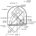
- FIGURE 2 illustrates an elevation view of gimbal assembly 100 after pivoting pivot assembly 150 to an angle 157 of 45 degrees, according to certain embodiments.
- base portion 152 of pivot assembly 150 is at a 45 degree angle 157 to window frame 120 and window 130
- payload receptacle 156 is perpendicular to base portion 152
- mirror 154 is at a 45 degree angle 155 to base portion 152 such that mirror 154 is perpendicular to window frame 120 and window 130.
- mirror 154 receives light 125 through window 130
- sensor 158 of payload receptacle 156 receives light 125 reflected by mirror 154.
- pivot assembly 150 is free to rotate counterclockwise 45 degrees such that base portion 152 is flush with window frame 120 and window 130.
- pivot assembly 150 is configured to move within enclosure 110 in a direction 210 that is perpendicular to first axis 160. This allows second axis 170 to shift along direction 210.
- pivot assembly 150 is configured to slide relative to window frame 120 and window 130. Any suitable translation device may be used to facilitate the movement of pivot assembly 150 along direction 210.
- pivot assembly 150 may slide along one or more tracks or v-grooves connected to window frame 120.
- the translation of pivot assembly 150 along window frame 120 may be facilitated by a linear screw.
- the translation device of gimbal assembly 100 is a rack and pinion device. In certain embodiments, the translation device reduces or eliminates backlash and/or jitter of pivot assembly 150.
- the shifting of second axis 170 along direction 210 enables pivot assembly 150 to pivot more than 45 degrees.
- space is created between mirror 154 and enclosure 110.
- the distance of this shift of pivot assembly 150 along direction 210 is directly proportional to angle 157.
- angle 157 For example, as pivot assembly 150 shifts 0.5 inches along direction 210 from second axis 170 toward first axis 160, maximum angle 157 increases by an increment of 11.25 degrees from 45 degrees to 56.25 degrees.
- maximum angle 157 increases by an additional increment of 11.25 degrees from 56.25 degrees to 67.5 degrees, and so on.
- a 360 degree rotation of enclosure 110 about first axis 160 in combination with a 55 degree pivot of pivot assembly 150 about second axis 170 may provide sensor 158 with a 110 degree field of regard with 50 percent obscuration.
- field of view 200 may be unobstructed by window frame 120 when angle 157 is at 45 degrees.
- angle 157 increases to 55 degrees, half of field of view 200 may be obstructed by window frame 120, resulting in 50 percent obscuration.
- Field of view 200 is the extent of light passing through window 130 that can be reflected by mirror 154 and received by sensor 158 at any given time.
- field of view 200 may be represented by an angle through which sensor 158 can detect light 125.
- field of view 200 is dependent on the position of pivot assembly 150 within enclosure 110. For example, field of view 200 changes as pivot assembly 150 pivots about second axis 170. As another example, field of view 200 changes as pivot assembly 150 rotates about first axis 160.
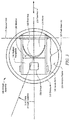
- FIGURE 3 illustrates a plan view of gimbal assembly 100, according to certain embodiments.
- enclosure 110 is centered on first axis of rotation 160, wherein one or more components of gimbal assembly 100 are configured to rotate 360 degrees in azimuth about first axis 160.
- gimbal assembly 100 is designed with two degrees of freedom for each axis (e.g., 2-axis azimuth rotation 310) for stability purposes, wherein the first degree of freedom is for low-rate gross displacements and the second degree of freedom is for high-rate fine displacements.
- Pivot assembly 150 is further configured to pivot within enclosure 110 about second axis 170 using guide rails 140.
- the 360 degree rotation of enclosure 110 about first axis 160 in combination with the 45 degree pivot of pivot assembly 150 about second axis 170 provide sensor 158 with an unobstructed field of regard.
- Pivot assembly 150 of the illustrated embodiment of FIGURE 3 is configured to move within enclosure 110 in direction 210 that is perpendicular to first axis 160. As pivot assembly 150 moves along direction 210 such that second axis 170 moves away from enclosure 110, the space between payload receptacle 156 and enclosure 110 is reduced and the space between the base of mirror 154 and enclosure 110 is increased, enabling mirror 154 to rotate greater than 45 degrees within enclosure 110.
- FIGURE 4 illustrates a tilted axis 410 of gimbal assembly 100, according to certain embodiments.
- enclosure 110 is configured to tilt such that one or more components of gimbal assembly 100 rotate 360 degrees about tilted axis 410 rather than about first axis 160.
- enclosure 110 is configured to tilt to avoid gimbal lock (e.g., a singularity point).
- Angle 420 between first axis 160 and tilted axis 410 may be any angle operable to avoid gimbal lock. As an example, angle 420 may be 5 degrees.
- this position is a singularity point where one or more components of gimbal assembly 100 must rotate in azimuth at a high rate to allow field of view 200 to pass through that point.
- the position of the singularity point may change to allow a lower rotation rate in azimuth for field of view 200 to pass through that point.
- actuators may separate the plane of the azimuth rotation from a mounting surface (e.g., a mounting surface of an aircraft), which results in singularity positioning 430.
- gimbal assembly 100 is installed on an aircraft platform and tracks an object (e.g., a moving object) by detecting light 125 (e.g., a wavelength) associated with the object.
- light 125 passes through window 130 and is reflected by mirror 154.
- Sensor 158 of gimbal assembly 100 receives reflected light 125 and tracks light 125 by pivoting about first axis 160 and second axis 170.
- pivot assembly 150 shifts along direction 210 to improve the field of regard of sensor 158.
- FIGURES 1 through 4 Modifications, additions, or omissions may be made to the embodiments depicted in FIGURES 1 through 4 .
- the embodiments may include more, fewer, or other components.
- gimbal assembly 100 may include one or more motors.
- the maximum degree of rotation of enclosure 110 about first axis 160 may be less than 360 degrees, and pivot assembly 150 may be operable to pivot more or less than 45 degrees about second axis 170.
- FIGURE 5 illustrates a computer system of gimbal assembly 100, according to certain embodiments.
- One or more computer systems 500 (e.g., computer system 190) perform one or more steps of one or more methods described or illustrated herein.
- one or more computer systems 500 provide functionality described or illustrated herein.
- software running on one or more computer systems 500 performs one or more steps of one or more methods described or illustrated herein or provides functionality described or illustrated herein.
- Particular embodiments include one or more portions of one or more computer systems 500.
- reference to a computer system may encompass a computing device, and vice versa, where appropriate.
- reference to a computer system may encompass one or more computer systems, where appropriate.
- computer system 500 may be an embedded computer system, a system-on-chip (SOC), a single-board computer system (SBC) (such as, for example, a computer-on-module (COM) or system-on-module (SOM)), a desktop computer system, a laptop or notebook computer system, an interactive kiosk, a mainframe, a mesh of computer systems, a mobile telephone, a personal digital assistant (PDA), a server, a tablet computer system, or a combination of two or more of these.
- SOC system-on-chip
- SBC single-board computer system
- COM computer-on-module
- SOM system-on-module
- desktop computer system such as, for example, a computer-on-module (COM) or system-on-module (SOM)
- laptop or notebook computer system such as, for example, a computer-on-module (COM) or system-on-module (SOM)
- desktop computer system such as, for example, a computer-on-module (COM
- computer system 500 may include one or more computer systems 500; be unitary or distributed; span multiple locations; span multiple machines; span multiple data centers; or reside in a cloud, which may include one or more cloud components in one or more networks.
- one or more computer systems 500 may perform without substantial spatial or temporal limitation one or more steps of one or more methods described or illustrated herein.
- one or more computer systems 500 may perform in real time or in batch mode one or more steps of one or more methods described or illustrated herein.
- One or more computer systems 500 may perform at different times or at different locations one or more steps of one or more methods described or illustrated herein, where appropriate.
- computer system 500 includes a processor 502 (e.g., processor 192) memory 504 (e.g., memory 194), storage 506, an input/output (I/O) interface 508, a communication interface 510, and a bus 512.
- processor 502 e.g., processor 192
- memory 504 e.g., memory 194
- storage 506 e.g., RAM
- I/O input/output
- communication interface 510 e.g., a communication interface 510
- bus 512 e.g., a bus 512.
- processor 502 includes hardware for executing instructions, such as those making up a computer program.
- processor 502 may retrieve (or fetch) the instructions from an internal register, an internal cache, memory 504, or storage 506; decode and execute them; and then write one or more results to an internal register, an internal cache, memory 504, or storage 506.
- processor 502 may include one or more internal caches for data, instructions, or addresses. This disclosure contemplates processor 502 including any suitable number of any suitable internal caches, where appropriate.
- processor 502 may include one or more instruction caches, one or more data caches, and one or more translation lookaside buffers (TLBs).
- TLBs translation lookaside buffers
- Instructions in the instruction caches may be copies of instructions in memory 504 or storage 506, and the instruction caches may speed up retrieval of those instructions by processor 502.
- Data in the data caches may be copies of data in memory 504 or storage 506 for instructions executing at processor 502 to operate on; the results of previous instructions executed at processor 502 for access by subsequent instructions executing at processor 502 or for writing to memory 504 or storage 506; or other suitable data.
- the data caches may speed up read or write operations by processor 502.
- the TLBs may speed up virtual-address translation for processor 502.
- processor 502 may include one or more internal registers for data, instructions, or addresses. This disclosure contemplates processor 502 including any suitable number of any suitable internal registers, where appropriate. Where appropriate, processor 502 may include one or more arithmetic logic units (ALUs); be a multi-core processor; or include one or more processors 502. Although this disclosure describes and illustrates a particular processor, this disclosure contemplates any suitable processor.
- ALUs
- memory 504 includes main memory for storing instructions for processor 502 to execute or data for processor 502 to operate on.
- computer system 500 may load instructions from storage 506 or another source (such as, for example, another computer system 500) to memory 504.
- Processor 502 may then load the instructions from memory 504 to an internal register or internal cache.
- processor 502 may retrieve the instructions from the internal register or internal cache and decode them.
- processor 502 may write one or more results (which may be intermediate or final results) to the internal register or internal cache.
- Processor 502 may then write one or more of those results to memory 504.
- processor 502 executes only instructions in one or more internal registers or internal caches or in memory 504 (as opposed to storage 506 or elsewhere) and operates only on data in one or more internal registers or internal caches or in memory 504 (as opposed to storage 506 or elsewhere).
- One or more memory buses (which may each include an address bus and a data bus) may couple processor 502 to memory 504.
- Bus 512 may include one or more memory buses, as described below.
- one or more memory management units reside between processor 502 and memory 504 and facilitate accesses to memory 504 requested by processor 502.
- memory 504 includes random access memory (RAM).
- This RAM may be volatile memory, where appropriate Where appropriate, this RAM may be dynamic RAM (DRAM) or static RAM (SRAM). Moreover, where appropriate, this RAM may be single-ported or multi-ported RAM. This disclosure contemplates any suitable RAM.
- Memory 504 may include one or more memory units 504, where appropriate. Although this disclosure describes and illustrates particular memory, this disclosure contemplates any suitable memory.
- storage 506 includes mass storage for data or instructions.
- storage 506 may include a hard disk drive (HDD), a floppy disk drive, flash memory, an optical disc, a magneto-optical disc, magnetic tape, or a Universal Serial Bus (USB) drive or a combination of two or more of these.
- Storage 506 may include removable or non-removable (or fixed) media, where appropriate.
- Storage 506 may be internal or external to computer system 500, where appropriate.
- storage 506 is non-volatile, solid-state memory.
- storage 506 includes read-only memory (ROM).
- this ROM may be mask-programmed ROM, programmable ROM (PROM), erasable PROM (EPROM), electrically erasable PROM (EEPROM), electrically alterable ROM (EAROM), or flash memory or a combination of two or more of these.
- This disclosure contemplates mass storage 506 taking any suitable physical form.
- Storage 506 may include one or more storage control units facilitating communication between processor 502 and storage 506, where appropriate.
- storage 506 may include one or more storages 506. Although this disclosure describes and illustrates particular storage, this disclosure contemplates any suitable storage.
- I/O interface 508 includes hardware, software, or both, providing one or more interfaces for communication between computer system 500 and one or more I/O devices.
- Computer system 500 may include one or more of these I/O devices, where appropriate.
- One or more of these I/O devices may enable communication between a person and computer system 500.
- an I/O device may include a keyboard, keypad, microphone, monitor, mouse, printer, scanner, speaker, still camera, stylus, tablet, touch screen, trackball, video camera, another suitable I/O device or a combination of two or more of these.
- An I/O device may include one or more sensors. This disclosure contemplates any suitable I/O devices and any suitable I/O interfaces 508 for them.
- I/O interface 508 may include one or more device or software drivers enabling processor 502 to drive one or more of these I/O devices.
- I/O interface 508 may include one or more I/O interfaces 508, where appropriate. Although this disclosure describes and illustrates a particular I/O interface, this disclosure contemplates any suitable I/O interface.
- communication interface 510 includes hardware, software, or both providing one or more interfaces for communication (such as, for example, packet-based communication) between computer system 500 and one or more other computer systems 500 or one or more networks.
- communication interface 510 may include a network interface controller (NIC) or network adapter for communicating with an Ethernet or other wire-based network or a wireless NIC (WNIC) or wireless adapter for communicating with a wireless network, such as a WI-FI network.
- NIC network interface controller
- WNIC wireless NIC
- WI-FI network wireless network
- computer system 500 may communicate with an ad hoc network, a personal area network (PAN), a local area network (LAN), a wide area network (WAN), a metropolitan area network (MAN), or one or more portions of the Internet or a combination of two or more of these.
- PAN personal area network
- LAN local area network
- WAN wide area network
- MAN metropolitan area network
- computer system 500 may communicate with a wireless PAN (WPAN) (such as, for example, a BLUETOOTH WPAN), a WI-FI network, a WI-MAX network, a cellular telephone network (such as, for example, a Global System for Mobile Communications (GSM) network), or other suitable wireless network or a combination of two or more of these.
- WPAN wireless PAN
- WI-FI wireless personal area network
- WI-MAX wireless personal area network
- WI-MAX wireless personal area network
- cellular telephone network such as, for example, a Global System for Mobile Communications (GSM) network
- GSM Global System
- bus 512 includes hardware, software, or both coupling components of computer system 500 to each other.
- bus 512 may include an Accelerated Graphics Port (AGP) or other graphics bus, an Enhanced Industry Standard Architecture (EISA) bus, a front-side bus (FSB), a HYPERTRANSPORT (HT) interconnect, an Industry Standard Architecture (ISA) bus, an INFINIBAND interconnect, a low-pin-count (LPC) bus, a memory bus, a Micro Channel Architecture (MCA) bus, a Peripheral Component Interconnect (PCI) bus, a PCI-Express (PCIe) bus, a serial advanced technology attachment (SATA) bus, a Video Electronics Standards Association local (VLB) bus, or another suitable bus or a combination of two or more of these.
- Bus 512 may include one or more buses 512, where appropriate.
- the components of computer system 500 may be integrated or separated. In some embodiments, components of computer system 500 may each be housed within a single chassis. The operations of computer system 500 may be performed by more, fewer, or other components. Additionally, operations of computer system 500 may be performed using any suitable logic that may include software, hardware, other logic, or any suitable combination of the preceding.
- a computer-readable non-transitory storage medium or media may include one or more semiconductor-based or other integrated circuits (ICs) (such, as for example, field-programmable gate arrays (FPGAs) or application-specific ICs (ASICs)), hard disk drives (HDDs), hybrid hard drives (HHDs), optical discs, optical disc drives (ODDs), magneto-optical discs, magneto-optical drives, floppy diskettes, floppy disk drives (FDDs), magnetic tapes, solid-state drives (SSDs), RAM-drives, SECURE DIGITAL cards or drives, any other suitable computer-readable non-transitory storage media, or any suitable combination of two or more of these, where appropriate.
- ICs such, as for example, field-programmable gate arrays (FPGAs) or application-specific ICs (ASICs)
- HDDs hard disk drives
- HHDs hybrid hard drives
- ODDs optical disc drives
- magneto-optical discs magneto-optical drives
- an apparatus or system or a component of an apparatus or system being adapted to, arranged to, capable of, configured to, enabled to, operable to, or operative to perform a particular function encompasses that apparatus, system, component, whether or not it or that particular function is activated, turned on, or unlocked, as long as that apparatus, system, or component is so adapted, arranged, capable, configured, enabled, operable, or operative.
Landscapes
- Physics & Mathematics (AREA)
- General Physics & Mathematics (AREA)
- Optics & Photonics (AREA)
- Studio Devices (AREA)
- Telescopes (AREA)
- Gyroscopes (AREA)
- Accessories Of Cameras (AREA)
Abstract
Description
- The present disclosure relates generally to a gimbal assembly, and more specifically to an advanced optical gimbal assembly.
- A standard optical gimbal mounted to an aircraft may include one or more optical sensors. Standard optical gimbals have look down capability, which can limit the field of regard. Further, the sensing capability of standard optical gimbals may be limited by obscurations.
- In accordance with the present disclosure, disadvantages and problems associated with standard optical gimbals may be reduced or eliminated.
- In one embodiment, a gimbal assembly includes an enclosure, a window frame, a window, one or more guide rails, and a pivot assembly. The enclosure is centered on a first axis. The window frame is coupled to the enclosure and the window is centered on the first axis and coupled to the window frame of the enclosure. The one or more guide rails are coupled within the enclosure to an interior portion of the enclosure. The pivot assembly is coupled to the interior portion of the enclosure and configured to pivot within the enclosure about a second axis using the one or more guide rails, the second axis being perpendicular to the first axis. The pivot assembly includes a base portion, a mirror, and a sensor. The mirror is coupled at an angle to the base portion and configured to reflect light received through the window and the sensor is removably coupled to the base portion and configured to receive the light reflected by the mirror. The second axis is located proximate to an end of the base portion and proximate to an end of the mirror, and the pivot assembly is further configured to move within the enclosure in a direction that is perpendicular to the first axis and rotate about the first axis.
- In some embodiments, a gimbal assembly includes an enclosure, a window coupled to the enclosure, and a pivot assembly coupled to an interior portion of the enclosure. The enclosure is configured to rotate about a first axis and the pivot assembly is configured to pivot within the enclosure about a second axis, the second axis being perpendicular to the first axis. The pivot assembly includes a base portion, a mirror coupled at an angle to the base portion and configured to reflect light received through the window, and a sensor configured to receive the light reflected by the mirror.
- In certain embodiments, a gimbal assembly includes a pivot assembly configured to be coupled to an interior portion of an enclosure. The pivot assembly is further configured to rotate about a first axis and to pivot within the enclosure about a second axis. The pivot assembly includes a base portion, a mirror coupled at an angle to the base portion and configured to reflect light received through a window of the enclosure, and a payload receptacle configured to house a sensor for receiving the light reflected by the mirror.
- Technical advantages of the present disclosure include a gimbal assembly that provides an improved field of regard over standard gimbal installations in special applications. In some embodiments, a 360 degree rotation of the pivot assembly about a first axis and a 45 degree rotation of the pivot assembly about a second axis provides the sensor with a 90 degree unobstructed field of regard. In certain embodiments, the gimbal's pivot assembly is configured to move within the enclosure in a direction perpendicular to the first axis, which allows the pivot assembly to rotate beyond 45 degrees to provide a field of regard greater than 90 degrees. In certain embodiments, obscurations caused by window frames are reduced or eliminated.
- As another advantage, certain embodiments of the present disclosure improve vehicle volume utilization. For example, a gimbal assembly may provide an unobstructed 90 degree field of regard with a single sensor, which eliminates the need to house multiple sensors. Further, in some embodiments, the gimbal assembly and its components are scalable. For example, the size of the gimbal assembly may be reduced for smaller aircraft platform (e.g., a four-seat, single-engine aircraft). Another technical advantage includes the gimbal assembly's ability to avoid gimbal lock in certain embodiments. For example, the gimbal assembly's first axis of rotation may be configured to tilt to avoid gimbal lock.
- For a more complete understanding of the disclosed embodiments and their features and advantages, reference is now made to the following description, taken in conjunction with the accompanying drawings, in which:
-
FIGURE 1 illustrates an elevation view of a gimbal assembly, according to certain embodiments; -
FIGURE 2 illustrates another elevation view of the gimbal assembly ofFIGURE 1 , according to certain embodiments; -
FIGURE 3 illustrates a plan view of the gimbal assembly ofFIGURE 1 , according to certain embodiments; -
FIGURE 4 illustrates a tilted axis of the gimbal assembly ofFIGURE 1 , according to certain embodiments; and -
FIGURE 5 illustrates a computer system that may be used to control the gimbal assembly ofFIGURE 1 , according to certain embodiments. - To facilitate a better understanding of the present disclosure, the following examples of certain embodiments are given. The following examples are not to be read to limit or define the scope of the disclosure. Embodiments of the present disclosure and its advantages are best understood by referring to
FIGURES 1 through 5 , where like numbers are used to indicate like and corresponding parts. - Standard optical gimbals used by aircraft may include one or more optical sensors. Standard optical gimbals have look down capability, which can limit the field of regard. Further, the sensing capability of standard optical gimbals may be limited by obscurations.
- To reduce or eliminate these and other problems, some embodiments of the present disclosure include a gimbal assembly that provides an improved field of regard over standard gimbal installations in special applications. In some embodiments, a 360 degree rotation of the pivot assembly about a first axis and a 45 degree rotation of the pivot assembly about a second axis provides the sensor with a 90 degree unobstructed field of regard. In certain embodiments, the gimbal's pivot assembly is configured to move within the enclosure in a direction perpendicular to the first axis, which allows the pivot assembly to rotate beyond 45 degrees to provide a field of regard greater than 90 degrees. In certain embodiments, obscurations caused by window frames are reduced or eliminated.
- As another advantage, certain embodiments of the present disclosure improve vehicle volume utilization. For example, a gimbal assembly may provide an unobstructed 90 degree field of regard with a single sensor, which eliminates the need to house multiple sensors. Further, in some embodiments, the gimbal assembly and its components are scalable. For example, the size of the gimbal assembly may be reduced for smaller aircraft platform (e.g., a four-seat, single-engine aircraft). Another technical advantage includes the gimbal assembly's ability to avoid gimbal lock in certain embodiments. For example, the gimbal assembly's enclosure may be configured to tilt to avoid gimbal lock.
- Other technical advantages will be readily apparent to one skilled in the art from the following figures, descriptions, and claims. Moreover, while specific advantages have been enumerated above, various embodiments may include all, some, or none of the enumerated advantages.
FIGURES 1-5 provide additional details relating to a gimbal assembly. -
FIGURE 1 illustrates an elevation view of agimbal assembly 100, according to certain embodiments. As shown in the embodiment ofFIGURE 1 ,gimbal assembly 100 includes anenclosure 110, awindow frame 120, awindow 130,guide rails 140, and apivot assembly 150. In certain embodiments,gimbal assembly 100 is mounted on a vehicle (e.g., an aircraft). In some embodiments,gimbal assembly 100 and its components are scalable. As an example, forgimbal assembly 100 mounted on an aircraft platform, the size ofgimbal assembly 100 and its corresponding components may depend on the size of the aircraft platform. - In general,
gimbal assembly 100 is an optical gimbal that may be installed on an aircraft to track objects. Whereas a sensor of a typical gimbal assembly looks straight ahead and receives light directly as the gimbal rotates about its mount, a sensor ofgimbal assembly 100 takes a different approach by receiving light reflected by a mirror. The mirror and sensor rotate and pivot within a limited space ofenclosure 110 to improve the field of regard over standard gimbal installations without wasting space on the aircraft's platform. -
Enclosure 110 is any enclosure configured to enclosepivot assembly 150.Enclosure 110 may be any shape or form. In the illustrated embodiment ofFIGURE 1 ,gimbal assembly 100 includes a dome-shapedenclosure 110 with a circular base. In some embodiments,enclosure 110 is configured to withstand loading conditions. For example,enclosure 110 may be configured to withstand static and/or dynamic loads associated with landing shock, in-flight buffeting, turbulence, and/or engine-induced three-dimensional vibrations. In certain embodiments,enclosure 110 may be composed of composite graphite fiber, aluminum, or any other suitable material or combination of materials. In certain embodiments,enclosure 110 is secured to a vehicle. For example,enclosure 110 may be bolted to an airframe of an aircraft. -
Enclosure 110 may include a seal. In some embodiments, the seal (e.g., a hermetic seal) is configured to exclude or minimize the passage of contaminants (e.g., fuel vapor, water vapor, sand, dust) into the interior ofenclosure 110. In certain embodiments, the seal may allow for the adjustment of the internal pressure ofenclosure 110 to equilibrate with the altitude of an aircraft. For example, the seal may include a filter pack configured to clean the air as it passes through. - In the illustrated embodiment of
FIGURE 1 ,enclosure 110 ofgimbal assembly 100 rotates about afirst axis 160.First axis 160 may have two degrees of freedom, wherein the first degree of freedom is for low-rate gross displacements and the second degree of freedom is for high-rate fine displacements. In some embodiments, enclosure may rotate 360 degrees in azimuth. In certain embodiments,enclosure 110 is configured to rotate in both a counterclockwise and clockwise direction. Alternatively,enclosure 110 may be configured to rotate either in a counterclockwise or clockwise direction. Gimbal assembly may include a motor (not illustrated) to facilitate the rotation ofenclosure 110 aboutfirst axis 160. - In certain embodiments,
pivot assembly 150 ofgimbal assembly 100 rotates aboutfirst axis 160. For example,enclosure 110 may remain fixed whilepivot assembly 160 rotates 360 degrees in azimuth. In certain embodiments,pivot assembly 150 rotates in both a counterclockwise and clockwise direction. Alternatively,pivot assembly 150 may be configured to rotate either in a counterclockwise or clockwise direction. Gimbal assembly may include a motor (not illustrated) to facilitate the rotation ofpivot assembly 150 aboutfirst axis 160. -
Gimbal assembly 100, as shown inFIGURE 1 , further includeswindow frame 120.Window frame 120 is any frame configured to supportwindow 130. In certain embodiments,window frame 120 is coupled toenclosure 110. In some embodiments,window frame 120 may be integrated withenclosure 110. For example,window frame 120 andenclosure 110 may be manufactured as one component.Window frame 120 may be composed of any suitable material (e.g., steel, aluminum, or a combination thereof). -
Gimbal assembly 100 ofFIGURE 1 further includeswindow 130.Window 130 may be any window operable to receive light 125. Further,window 130 may be any shape. In certain embodiments, the shape ofwindow 130 is the enclosing footprint of all possible angles for the passage of light 125 that can be sensed by the one or more sensors ofgimbal assembly 100. In the illustrated embodiment,window 130 is the shape of a rounded rectangle, whereinwindow 130 is centered on first axis ofrotation 160. In some embodiments,window 130 may include two hemispherical windows, whereinwindow frame 120 divides the two hemispherical windows. In some embodiments,window 130 is off-center from first axis ofrotation 160 and is irregular in shape. - As illustrated in
FIGURE 1 ,gimbal assembly 100 may includepivot assembly 150. In some embodiments,pivot assembly 150 is coupled to an interior portion ofenclosure 110 and is configured to pivot withinenclosure 110 about asecond axis 170. In some embodiments,pivot assembly 150 may utilize one or more guide rails 140. For example,pivot assembly 150 may utilize aguide rail 140 on each side ofpivot assembly 150.Guide rails 140 may be made of hardened steel, aluminum, or any other material or combination of materials operable to assist the rotation ofpivot assembly 150. In certain embodiments,guide rails 140 may limit the range of motion ofpivot assembly 150. For example, guide rails may limitpivot assembly 150's maximum range of motion to 45 degrees. As another example, guide rails may limitpivot assembly 150's maximum range of motion to 50 degrees. -
Pivot assembly 150 may include any components that permitpivot assembly 150 to pivot aboutsecond axis 170 withinenclosure 110. For example,pivot assembly 150 may include a rotating member (e.g., a metal rod) alongsecond axis 170 that includes a first end and a second end, wherein the first end and the second end are connected towindow frame 120 by a first joint and a second joint, respectively. In certain embodiments, each joint allows the rotating member to rotate but prevents the rotating member from vertical and/or lateral displacement. In the illustrated embodiment ofFIGURE 1 ,second axis 170 is perpendicular tofirst axis 160 but does not intersectfirst axis 160. - In certain embodiments,
pivot assembly 150 includes abase portion 152, amirror 154, apayload receptacle 156, and asensor 158. In the illustrated embodiment ofFIGURE 1 ,base portion 152 includes a first end and a second end, wherein the first end is coupled to guiderails 140 and the second end is proximate tosecond axis 170. In some embodiments,base portion 170 is configured to pivot aboutsecond axis 170 withinenclosure 110 as illustrated inFIGURE 2 . - As shown in the illustrated embodiment of
FIGURE 1 ,mirror 154 is coupled tobase portion 152 atsecond axis 170.Mirror 154 is any object with a reflective surface. For example,mirror 154 may be an optical mirror used to reflect light 125. In some embodiments,mirror 154 is coupled at anangle 155 tobase portion 152. For example,mirror 154 may be coupled at anangle 155 of approximately 45 degrees tobase portion 152. In certain embodiments,angle 155 betweenmirror 154 andbase portion 152 remains fixed asmirror 154 andbase portion 152 pivot aboutsecond axis 170. -
Pivot assembly 150 may further includepayload receptacle 156, as illustrated in the embodiment ofFIGURE 1 .Payload receptacle 156 is any receptacle configured tohouse sensor 158.Sensor 158 is any sensor configured to receive light 125. For example,sensor 158 may be a physical light sensor configured to receive light 125 reflected bymirror 154. The type ofsensor 158 may determine the type ofwindow 130 selected forgimbal assembly 100. For example,gimbal assembly 100 includinginfrared sensor 158 may includewindow 130 that allows the passage of infrared wavelengths. In some embodiments,pivot assembly 150 includesmultiple sensors 158, andpayload receptacle 156 is configured to house the multiple sensors. - In some embodiments,
payload receptacle 156 is removably coupled tobase portion 152. For example, a first payload receptacle 156a housing a first sensor 158a may be replaced with a second payload receptacle 156b housing a second sensor 158b. In certain embodiments,sensor 158 may be removably coupled topayload receptacle 156. For example, sensor 158a ofpayload receptacle 156 may be replaced with sensor 158b. As another example, a first combination of sensors 158a, 158b, and 158c housed inpayload receptacle 156 may be replaced with a second combination of sensors 158d, 158e, and 158f. - In certain embodiments,
payload receptacle 156 includes a first end and a second end, wherein the first end ofpayload receptacle 156 is coupled tobase portion 152 and the second end ofpayload receptacle 156 is coupled tomirror 154.Payload receptacle 156 may be configured to pivot withinenclosure 110 aboutsecond axis 170. In some embodiments,payload receptacle 156,base portion 152, andmirror 154 remain fixed relative to each other aspivot assembly 150 pivots aboutsecond axis 170. - In the illustrated embodiment of
FIGURE 1 ,base portion 152 ofpivot assembly 150 is flush withwindow frame 120 andwindow 130,payload receptacle 156 is flush with and perpendicular tobase portion 152, andmirror 154 is at a 45degree angle 155 tobase portion 152. At a moment in time,mirror 154 receives light 125 throughwindow 130, andsensor 158 ofpayload receptacle 156 receives light 125 reflected bymirror 154. - In some embodiments,
window frame 120 andwindow 130 restrainpivot assembly 150 from rotating in a counterclockwise direction. However,pivot assembly 150 is free to rotate in a clockwise direction withinenclosure 110. The clockwise rotation ofpivot assembly 150 is restrained to a maximum of 45 degrees in the position shown in the illustrated embodiment ofFIGURE 1 . In certain embodiments, the rotation ofpivot assembly 150 aboutsecond axis 170 is limited by the available space ofenclosure 110. A 360 degree rotation ofenclosure 110 aboutfirst axis 160 in combination with a 45 degree rotation ofpivot assembly 150 aboutsecond axis 170 providesensor 158 with an unobstructed 90 degree field of regard. In certain embodiments,pivot assembly 150 is operable to pivot more than 45 degrees, as described below inFIGURE 2 . - Field of
view 180 is the extent of light passing throughwindow 130 that can be reflected bymirror 154 and received bysensor 158 at any given time. In certain embodiments, field ofview 180 may be represented by an angle through whichsensor 158 can detect light 125. In the illustrated embodiment ofFIGURE 1 , field ofview 180 is dependent on the position ofpivot assembly 150 withinenclosure 110. For example, field ofview 180 changes aspivot assembly 150 pivots aboutsecond axis 170. - In certain embodiments,
gimbal assembly 100 further includes acomputer system 190.Computer system 190 may include one ormore processors 192, one ormore memory units 194, and one ormore interfaces 196.Processor 192 may control one or more functions ofgimbal assembly 100. For example,processor 192 may control the rotation ofenclosure 110 aboutfirst axis 160. As another example,processor 192 may control the rotation ofpivot assembly 150 aboutsecond axis 170. In some embodiments,computer system 190 may be configured to communicate with one or more computer systems external togimbal assembly 100. Certain embodiments ofcomputer system 190 are discussed in more detail in reference toFIGURE 5 below. -
FIGURE 2 illustrates an elevation view ofgimbal assembly 100 after pivotingpivot assembly 150 to anangle 157 of 45 degrees, according to certain embodiments. As shown inFIGURE 2 ,base portion 152 ofpivot assembly 150 is at a 45degree angle 157 towindow frame 120 andwindow 130,payload receptacle 156 is perpendicular tobase portion 152, andmirror 154 is at a 45degree angle 155 tobase portion 152 such thatmirror 154 is perpendicular towindow frame 120 andwindow 130. At a moment in time,mirror 154 receives light 125 throughwindow 130, andsensor 158 ofpayload receptacle 156 receives light 125 reflected bymirror 154. In the illustrated embodiment ofFIGURE 2 ,pivot assembly 150 is free to rotate counterclockwise 45 degrees such thatbase portion 152 is flush withwindow frame 120 andwindow 130. - As shown in the embodiment of
FIGURE 2 ,pivot assembly 150 is configured to move withinenclosure 110 in adirection 210 that is perpendicular tofirst axis 160. This allowssecond axis 170 to shift alongdirection 210. In certain embodiments,pivot assembly 150 is configured to slide relative towindow frame 120 andwindow 130. Any suitable translation device may be used to facilitate the movement ofpivot assembly 150 alongdirection 210. For example,pivot assembly 150 may slide along one or more tracks or v-grooves connected towindow frame 120. As another example, the translation ofpivot assembly 150 alongwindow frame 120 may be facilitated by a linear screw. In some embodiments, the translation device ofgimbal assembly 100 is a rack and pinion device. In certain embodiments, the translation device reduces or eliminates backlash and/or jitter ofpivot assembly 150. - The shifting of
second axis 170 alongdirection 210 enablespivot assembly 150 to pivot more than 45 degrees. Aspivot assembly 150 shifts alongdirection 210 in order to movesecond axis 170 away fromenclosure 110, space is created betweenmirror 154 andenclosure 110. In certain embodiments, the distance of this shift ofpivot assembly 150 alongdirection 210 is directly proportional toangle 157. For example, aspivot assembly 150 shifts 0.5 inches alongdirection 210 fromsecond axis 170 towardfirst axis 160,maximum angle 157 increases by an increment of 11.25 degrees from 45 degrees to 56.25 degrees. Similarly, aspivot assembly 150 shifts an additional 0.5 inches (1 inch total) alongdirection 210 fromsecond axis 170 towardfirst axis 160,maximum angle 157 increases by an additional increment of 11.25 degrees from 56.25 degrees to 67.5 degrees, and so on. - This created space between
mirror 154 andenclosure 110 that allowspivot assembly 150 to pivot beyond 45 degrees enables a wider field of regard (e.g., 110 degrees). A 360 degree rotation ofenclosure 110 aboutfirst axis 160 in combination with a 55 degree pivot ofpivot assembly 150 aboutsecond axis 170 may providesensor 158 with a 110 degree field of regard with 50 percent obscuration. For example, field ofview 200 may be unobstructed bywindow frame 120 whenangle 157 is at 45 degrees. Whenangle 157 increases to 55 degrees, half of field ofview 200 may be obstructed bywindow frame 120, resulting in 50 percent obscuration. - Field of
view 200 is the extent of light passing throughwindow 130 that can be reflected bymirror 154 and received bysensor 158 at any given time. In certain embodiments, field ofview 200 may be represented by an angle through whichsensor 158 can detect light 125. In the illustrated embodiment ofFIGURE 1 , field ofview 200 is dependent on the position ofpivot assembly 150 withinenclosure 110. For example, field ofview 200 changes aspivot assembly 150 pivots aboutsecond axis 170. As another example, field ofview 200 changes aspivot assembly 150 rotates aboutfirst axis 160. -
FIGURE 3 illustrates a plan view ofgimbal assembly 100, according to certain embodiments. In the illustrated embodiment ofFIGURE 3 ,enclosure 110 is centered on first axis ofrotation 160, wherein one or more components ofgimbal assembly 100 are configured to rotate 360 degrees in azimuth aboutfirst axis 160. In certain embodiments,gimbal assembly 100 is designed with two degrees of freedom for each axis (e.g., 2-axis azimuth rotation 310) for stability purposes, wherein the first degree of freedom is for low-rate gross displacements and the second degree of freedom is for high-rate fine displacements.Pivot assembly 150 is further configured to pivot withinenclosure 110 aboutsecond axis 170 usingguide rails 140. The 360 degree rotation ofenclosure 110 aboutfirst axis 160 in combination with the 45 degree pivot ofpivot assembly 150 aboutsecond axis 170 providesensor 158 with an unobstructed field of regard. -
Pivot assembly 150 of the illustrated embodiment ofFIGURE 3 is configured to move withinenclosure 110 indirection 210 that is perpendicular tofirst axis 160. Aspivot assembly 150 moves alongdirection 210 such thatsecond axis 170 moves away fromenclosure 110, the space betweenpayload receptacle 156 andenclosure 110 is reduced and the space between the base ofmirror 154 andenclosure 110 is increased, enablingmirror 154 to rotate greater than 45 degrees withinenclosure 110. -
FIGURE 4 illustrates a tiltedaxis 410 ofgimbal assembly 100, according to certain embodiments. As illustrated in the embodiment ofFIGURE 4 ,enclosure 110 is configured to tilt such that one or more components ofgimbal assembly 100 rotate 360 degrees about tiltedaxis 410 rather than aboutfirst axis 160. In certain embodiments,enclosure 110 is configured to tilt to avoid gimbal lock (e.g., a singularity point).Angle 420 betweenfirst axis 160 and tiltedaxis 410 may be any angle operable to avoid gimbal lock. As an example,angle 420 may be 5 degrees. - In certain embodiments, when
gimbal assembly 100 is positioned such that the field ofview 200 is perpendicular towindow 130, this position is a singularity point where one or more components ofgimbal assembly 100 must rotate in azimuth at a high rate to allow field ofview 200 to pass through that point. By changing the angle offirst axis 160, the position of the singularity point may change to allow a lower rotation rate in azimuth for field ofview 200 to pass through that point. To mechanize tiltedaxis 410, actuators may separate the plane of the azimuth rotation from a mounting surface (e.g., a mounting surface of an aircraft), which results insingularity positioning 430. - In operation,
gimbal assembly 100 is installed on an aircraft platform and tracks an object (e.g., a moving object) by detecting light 125 (e.g., a wavelength) associated with the object. In some embodiments, light 125 passes throughwindow 130 and is reflected bymirror 154.Sensor 158 ofgimbal assembly 100 receives reflected light 125 and tracks light 125 by pivoting aboutfirst axis 160 andsecond axis 170. In certain embodiments,pivot assembly 150 shifts alongdirection 210 to improve the field of regard ofsensor 158. - Modifications, additions, or omissions may be made to the embodiments depicted in
FIGURES 1 through 4 . The embodiments may include more, fewer, or other components. For example, in addition to the components shown inFIGURES 1-4 ,gimbal assembly 100 may include one or more motors. As another example, the maximum degree of rotation ofenclosure 110 aboutfirst axis 160 may be less than 360 degrees, andpivot assembly 150 may be operable to pivot more or less than 45 degrees aboutsecond axis 170. -
FIGURE 5 illustrates a computer system ofgimbal assembly 100, according to certain embodiments. One or more computer systems 500 (e.g., computer system 190) perform one or more steps of one or more methods described or illustrated herein. In particular embodiments, one ormore computer systems 500 provide functionality described or illustrated herein. In particular embodiments, software running on one ormore computer systems 500 performs one or more steps of one or more methods described or illustrated herein or provides functionality described or illustrated herein. Particular embodiments include one or more portions of one ormore computer systems 500. Herein, reference to a computer system may encompass a computing device, and vice versa, where appropriate. Moreover, reference to a computer system may encompass one or more computer systems, where appropriate. - This disclosure contemplates any suitable number of
computer systems 500. This disclosure contemplatescomputer system 500 taking any suitable physical form. As example and not by way of limitation,computer system 500 may be an embedded computer system, a system-on-chip (SOC), a single-board computer system (SBC) (such as, for example, a computer-on-module (COM) or system-on-module (SOM)), a desktop computer system, a laptop or notebook computer system, an interactive kiosk, a mainframe, a mesh of computer systems, a mobile telephone, a personal digital assistant (PDA), a server, a tablet computer system, or a combination of two or more of these. Where appropriate,computer system 500 may include one ormore computer systems 500; be unitary or distributed; span multiple locations; span multiple machines; span multiple data centers; or reside in a cloud, which may include one or more cloud components in one or more networks. Where appropriate, one ormore computer systems 500 may perform without substantial spatial or temporal limitation one or more steps of one or more methods described or illustrated herein. As an example and not by way of limitation, one ormore computer systems 500 may perform in real time or in batch mode one or more steps of one or more methods described or illustrated herein. One ormore computer systems 500 may perform at different times or at different locations one or more steps of one or more methods described or illustrated herein, where appropriate. - In particular embodiments,
computer system 500 includes a processor 502 (e.g., processor 192) memory 504 (e.g., memory 194),storage 506, an input/output (I/O)interface 508, a communication interface 510, and a bus 512. Although this disclosure describes and illustrates a particular computer system having a particular number of particular components in a particular arrangement, this disclosure contemplates any suitable computer system having any suitable number of any suitable components in any suitable arrangement. - In particular embodiments,
processor 502 includes hardware for executing instructions, such as those making up a computer program. As an example and not by way of limitation, to execute instructions,processor 502 may retrieve (or fetch) the instructions from an internal register, an internal cache,memory 504, orstorage 506; decode and execute them; and then write one or more results to an internal register, an internal cache,memory 504, orstorage 506. In particular embodiments,processor 502 may include one or more internal caches for data, instructions, or addresses. This disclosure contemplatesprocessor 502 including any suitable number of any suitable internal caches, where appropriate. As an example and not by way of limitation,processor 502 may include one or more instruction caches, one or more data caches, and one or more translation lookaside buffers (TLBs). Instructions in the instruction caches may be copies of instructions inmemory 504 orstorage 506, and the instruction caches may speed up retrieval of those instructions byprocessor 502. Data in the data caches may be copies of data inmemory 504 orstorage 506 for instructions executing atprocessor 502 to operate on; the results of previous instructions executed atprocessor 502 for access by subsequent instructions executing atprocessor 502 or for writing tomemory 504 orstorage 506; or other suitable data. The data caches may speed up read or write operations byprocessor 502. The TLBs may speed up virtual-address translation forprocessor 502. In particular embodiments,processor 502 may include one or more internal registers for data, instructions, or addresses. This disclosure contemplatesprocessor 502 including any suitable number of any suitable internal registers, where appropriate. Where appropriate,processor 502 may include one or more arithmetic logic units (ALUs); be a multi-core processor; or include one ormore processors 502. Although this disclosure describes and illustrates a particular processor, this disclosure contemplates any suitable processor. - In particular embodiments,
memory 504 includes main memory for storing instructions forprocessor 502 to execute or data forprocessor 502 to operate on. As an example and not by way of limitation,computer system 500 may load instructions fromstorage 506 or another source (such as, for example, another computer system 500) tomemory 504.Processor 502 may then load the instructions frommemory 504 to an internal register or internal cache. To execute the instructions,processor 502 may retrieve the instructions from the internal register or internal cache and decode them. During or after execution of the instructions,processor 502 may write one or more results (which may be intermediate or final results) to the internal register or internal cache.Processor 502 may then write one or more of those results tomemory 504. In particular embodiments,processor 502 executes only instructions in one or more internal registers or internal caches or in memory 504 (as opposed tostorage 506 or elsewhere) and operates only on data in one or more internal registers or internal caches or in memory 504 (as opposed tostorage 506 or elsewhere). One or more memory buses (which may each include an address bus and a data bus) may coupleprocessor 502 tomemory 504. Bus 512 may include one or more memory buses, as described below. In particular embodiments, one or more memory management units (MMUs) reside betweenprocessor 502 andmemory 504 and facilitate accesses tomemory 504 requested byprocessor 502. In particular embodiments,memory 504 includes random access memory (RAM). This RAM may be volatile memory, where appropriate Where appropriate, this RAM may be dynamic RAM (DRAM) or static RAM (SRAM). Moreover, where appropriate, this RAM may be single-ported or multi-ported RAM. This disclosure contemplates any suitable RAM.Memory 504 may include one ormore memory units 504, where appropriate. Although this disclosure describes and illustrates particular memory, this disclosure contemplates any suitable memory. - In particular embodiments,
storage 506 includes mass storage for data or instructions. As an example and not by way of limitation,storage 506 may include a hard disk drive (HDD), a floppy disk drive, flash memory, an optical disc, a magneto-optical disc, magnetic tape, or a Universal Serial Bus (USB) drive or a combination of two or more of these.Storage 506 may include removable or non-removable (or fixed) media, where appropriate.Storage 506 may be internal or external tocomputer system 500, where appropriate. In particular embodiments,storage 506 is non-volatile, solid-state memory. In particular embodiments,storage 506 includes read-only memory (ROM). Where appropriate, this ROM may be mask-programmed ROM, programmable ROM (PROM), erasable PROM (EPROM), electrically erasable PROM (EEPROM), electrically alterable ROM (EAROM), or flash memory or a combination of two or more of these. This disclosure contemplatesmass storage 506 taking any suitable physical form.Storage 506 may include one or more storage control units facilitating communication betweenprocessor 502 andstorage 506, where appropriate. Where appropriate,storage 506 may include one ormore storages 506. Although this disclosure describes and illustrates particular storage, this disclosure contemplates any suitable storage. - In particular embodiments, I/
O interface 508 includes hardware, software, or both, providing one or more interfaces for communication betweencomputer system 500 and one or more I/O devices.Computer system 500 may include one or more of these I/O devices, where appropriate. One or more of these I/O devices may enable communication between a person andcomputer system 500. As an example and not by way of limitation, an I/O device may include a keyboard, keypad, microphone, monitor, mouse, printer, scanner, speaker, still camera, stylus, tablet, touch screen, trackball, video camera, another suitable I/O device or a combination of two or more of these. An I/O device may include one or more sensors. This disclosure contemplates any suitable I/O devices and any suitable I/O interfaces 508 for them. Where appropriate, I/O interface 508 may include one or more device or softwaredrivers enabling processor 502 to drive one or more of these I/O devices. I/O interface 508 may include one or more I/O interfaces 508, where appropriate. Although this disclosure describes and illustrates a particular I/O interface, this disclosure contemplates any suitable I/O interface. - In particular embodiments, communication interface 510 includes hardware, software, or both providing one or more interfaces for communication (such as, for example, packet-based communication) between
computer system 500 and one or moreother computer systems 500 or one or more networks. As an example and not by way of limitation, communication interface 510 may include a network interface controller (NIC) or network adapter for communicating with an Ethernet or other wire-based network or a wireless NIC (WNIC) or wireless adapter for communicating with a wireless network, such as a WI-FI network. This disclosure contemplates any suitable network and any suitable communication interface 510 for it. As an example and not by way of limitation,computer system 500 may communicate with an ad hoc network, a personal area network (PAN), a local area network (LAN), a wide area network (WAN), a metropolitan area network (MAN), or one or more portions of the Internet or a combination of two or more of these. One or more portions of one or more of these networks may be wired or wireless. As an example,computer system 500 may communicate with a wireless PAN (WPAN) (such as, for example, a BLUETOOTH WPAN), a WI-FI network, a WI-MAX network, a cellular telephone network (such as, for example, a Global System for Mobile Communications (GSM) network), or other suitable wireless network or a combination of two or more of these.Computer system 500 may include any suitable communication interface 510 for any of these networks, where appropriate. Communication interface 510 may include one or more communication interfaces 510, where appropriate. Although this disclosure describes and illustrates a particular communication interface, this disclosure contemplates any suitable communication interface. - In particular embodiments, bus 512 includes hardware, software, or both coupling components of
computer system 500 to each other. As an example and not by way of limitation, bus 512 may include an Accelerated Graphics Port (AGP) or other graphics bus, an Enhanced Industry Standard Architecture (EISA) bus, a front-side bus (FSB), a HYPERTRANSPORT (HT) interconnect, an Industry Standard Architecture (ISA) bus, an INFINIBAND interconnect, a low-pin-count (LPC) bus, a memory bus, a Micro Channel Architecture (MCA) bus, a Peripheral Component Interconnect (PCI) bus, a PCI-Express (PCIe) bus, a serial advanced technology attachment (SATA) bus, a Video Electronics Standards Association local (VLB) bus, or another suitable bus or a combination of two or more of these. Bus 512 may include one or more buses 512, where appropriate. Although this disclosure describes and illustrates a particular bus, this disclosure contemplates any suitable bus or interconnect. - The components of
computer system 500 may be integrated or separated. In some embodiments, components ofcomputer system 500 may each be housed within a single chassis. The operations ofcomputer system 500 may be performed by more, fewer, or other components. Additionally, operations ofcomputer system 500 may be performed using any suitable logic that may include software, hardware, other logic, or any suitable combination of the preceding. - Herein, a computer-readable non-transitory storage medium or media may include one or more semiconductor-based or other integrated circuits (ICs) (such, as for example, field-programmable gate arrays (FPGAs) or application-specific ICs (ASICs)), hard disk drives (HDDs), hybrid hard drives (HHDs), optical discs, optical disc drives (ODDs), magneto-optical discs, magneto-optical drives, floppy diskettes, floppy disk drives (FDDs), magnetic tapes, solid-state drives (SSDs), RAM-drives, SECURE DIGITAL cards or drives, any other suitable computer-readable non-transitory storage media, or any suitable combination of two or more of these, where appropriate. A computer-readable non-transitory storage medium may be volatile, non-volatile, or a combination of volatile and non-volatile, where appropriate.
- Herein, "or" is inclusive and not exclusive, unless expressly indicated otherwise or indicated otherwise by context. Therefore, herein, "A or B" means "A, B, or both," unless expressly indicated otherwise or indicated otherwise by context. Moreover, "and" is both joint and several, unless expressly indicated otherwise or indicated otherwise by context. Therefore, herein, "A and B" means "A and B, jointly or severally," unless expressly indicated otherwise or indicated otherwise by context.
- The scope of this disclosure encompasses all changes, substitutions, variations, alterations, and modifications to the example embodiments described or illustrated herein that a person having ordinary skill in the art would comprehend. The scope of this disclosure is not limited to the example embodiments described or illustrated herein. Moreover, although this disclosure describes and illustrates respective embodiments herein as including particular components, elements, functions, operations, or steps, any of these embodiments may include any combination or permutation of any of the components, elements, functions, operations, or steps described or illustrated anywhere herein that a person having ordinary skill in the art would comprehend. Furthermore, reference in the appended claims to an apparatus or system or a component of an apparatus or system being adapted to, arranged to, capable of, configured to, enabled to, operable to, or operative to perform a particular function encompasses that apparatus, system, component, whether or not it or that particular function is activated, turned on, or unlocked, as long as that apparatus, system, or component is so adapted, arranged, capable, configured, enabled, operable, or operative.
Claims (12)
- A gimbal assembly, comprising:an enclosure centered on a first axis;a window frame coupled to the enclosure;a window centered on the first axis and coupled to the window frame of the enclosure;one or more guide rails coupled within the enclosure to an interior portion of the enclosure; anda pivot assembly coupled to the interior portion of the enclosure and configured to pivot within the enclosure about a second axis using the one or more guide rails, the second axis being perpendicular to the first axis, the pivot assembly comprising:a base portion;a mirror coupled at an angle to the base portion and configured to reflect light received through the window; anda sensor removably coupled to the base portion and configured to receive the light reflected by the mirror;wherein:the second axis is located proximate to an end of the base portion and proximate to an end of the mirror; andthe pivot assembly is further configured to:move within the enclosure in a direction that is perpendicular to the first axis; androtate about the first axis.
- A gimbal assembly, comprising:an enclosure configured to rotate about a first axis;a window coupled to the enclosure; anda pivot assembly coupled to an interior portion of the enclosure and configured to pivot within the enclosure about a second axis, the second axis being perpendicular to the first axis, the pivot assembly comprising:a base portion;a mirror coupled at an angle to the base portion and configured to reflect light received through the window; anda sensor configured to receive the light reflected by the mirror.
- A gimbal assembly, comprising:a pivot assembly configured to be coupled to an interior portion of an enclosure, the pivot assembly further configured to rotate about a first axis and to pivot within the enclosure about a second axis, the pivot assembly comprising:a base portion;a mirror coupled at an angle to the base portion and configured to reflect light received through a window of the enclosure; anda payload receptacle configured to house a sensor for receiving the light reflected by the mirror.
- The gimbal assembly of Claim 1, wherein the pivot assembly is further configured to:rotate 360 degrees about the first axis; andpivot 45 degrees within the enclosure about the second axis; orthe gimbal assembly of Claim 2, wherein the enclosure is configured to rotate 360 degrees about the first axis and the pivot assembly is configured to pivot 45 degrees within the enclosure about the second axis; orthe gimbal assembly of Claim 3, wherein the pivot assembly is configured to:rotate 360 degrees about the first axis; andpivot 45 degrees within the enclosure about the second axis.
- The gimbal assembly of Claim 1 or of Claim 3 or of Claim 4, wherein a 360 degree rotation of the pivot assembly about the first axis in combination with a 45 degree rotation of the pivot assembly about the second axis provide the sensor with an unobstructed 90 degree field of regard; or
the gimbal assembly of Claim 2 or of Claim 4, wherein a 360 degree rotation of the enclosure about the first axis in combination with a 45 degree rotation of the pivot assembly about the second axis provide the sensor with an unobstructed 90 degree field of regard. - The gimbal assembly of Claim 1 or of Claim 2 or of Claim 3 or of any preceding claim, wherein the first axis does not intersect the second axis.
- The gimbal assembly of Claim 1 or of Claim 2 or of Claim 3 or of any preceding claim, wherein the first axis of rotation is configured to tilt to avoid gimbal lock.
- The gimbal assembly of Claim 1 or Claim 2 or of any preceding claim dependent directly or indirectly from Claim 1 or Claim 2, further comprising one or more guide rails coupled within the enclosure to an interior portion of the enclosure.
- The gimbal assembly of Claim 1 or Claim 2 or any preceding claim, wherein the pivot assembly is configured to move within the enclosure in a direction that is perpendicular to the first axis.
- The gimbal assembly of Claim 1 or of Claim 2 or of any preceding claim, wherein the second axis is located proximate to an end of the base portion and proximate to an end of the mirror.
- The gimbal assembly of Claim 3, the pivot assembly further configured to move within the enclosure in a direction that is perpendicular to the first axis.
- The gimbal assembly of Claim 3, wherein the axis is located proximate to an end of the base portion and proximate to an end of the mirror.
Applications Claiming Priority (1)
| Application Number | Priority Date | Filing Date | Title |
|---|---|---|---|
| US15/159,022 US9885851B2 (en) | 2016-05-19 | 2016-05-19 | Advanced optical gimbal |
Publications (2)
| Publication Number | Publication Date |
|---|---|
| EP3258303A1 true EP3258303A1 (en) | 2017-12-20 |
| EP3258303B1 EP3258303B1 (en) | 2020-04-01 |
Family
ID=58668772
Family Applications (1)
| Application Number | Title | Priority Date | Filing Date |
|---|---|---|---|
| EP17169151.2A Active EP3258303B1 (en) | 2016-05-19 | 2017-05-02 | Advanced optical gimbal |
Country Status (3)
| Country | Link |
|---|---|
| US (1) | US9885851B2 (en) |
| EP (1) | EP3258303B1 (en) |
| JP (1) | JP6495373B2 (en) |
Families Citing this family (4)
| Publication number | Priority date | Publication date | Assignee | Title |
|---|---|---|---|---|
| CN109839102B (en) * | 2017-11-27 | 2021-05-04 | 灵踪科技(深圳)有限公司 | Optical curved surface positioning method and device |
| CN110161456B (en) * | 2018-02-13 | 2021-07-20 | 灵踪科技(深圳)有限公司 | Optical curved surface rapid positioning device |
| KR102494681B1 (en) * | 2018-04-13 | 2023-02-02 | 삼성전자주식회사 | Camera assembly and Electronic device having the same |
| CN115032758B (en) * | 2022-01-21 | 2024-01-23 | 广州立景创新科技有限公司 | Adjustable mirror motor group |
Citations (3)
| Publication number | Priority date | Publication date | Assignee | Title |
|---|---|---|---|---|
| US20070008514A1 (en) * | 2005-07-08 | 2007-01-11 | Lockheed Martin Corporation | LADAR system with SAL follower |
| WO2007033033A2 (en) * | 2005-09-12 | 2007-03-22 | Honeywell International Inc. | Apparatus and method for providing pointing capability for a fixed camera |
| EP1965225A2 (en) * | 2007-02-28 | 2008-09-03 | Denso Wave Incorporated | Laser radar apparatus for three-dimensional detection of objects |
Family Cites Families (29)
| Publication number | Priority date | Publication date | Assignee | Title |
|---|---|---|---|---|
| US4386848A (en) * | 1980-08-11 | 1983-06-07 | Martin Marietta Corporation | Optical target tracking and designating system |
| US4717822A (en) | 1986-08-04 | 1988-01-05 | Hughes Aircraft Company | Rosette scanning surveillance sensor |
| US4886330A (en) | 1986-08-07 | 1989-12-12 | James Linick | Infra red imaging system |
| JPS6378624A (en) * | 1986-09-22 | 1988-04-08 | Mitsubishi Electric Corp | Optical space communication equipment |
| US5143334A (en) | 1990-05-21 | 1992-09-01 | Rockwell International Corporation | Low moving mass two axis gimbal |
| US6129307A (en) | 1991-09-04 | 2000-10-10 | Northrop Grumman Corporation | Stabilized optical gimbal assembly |
| JP2806659B2 (en) * | 1991-10-17 | 1998-09-30 | 株式会社エイ・ティ・アール光電波通信研究所 | Direction tracking device |
| DE4135260C1 (en) | 1991-10-25 | 1993-02-25 | Bodenseewerk Geraetetechnik Gmbh, 7770 Ueberlingen, De | |
| IL100634A (en) | 1992-01-12 | 1996-12-05 | Israel State | Stabilized support for instruments such as forward looking infrared (FLIR) units |
| US5751460A (en) | 1995-10-11 | 1998-05-12 | Hughes Aircraft Company | Optical system with an articulated mirror unit |
| US5936771A (en) | 1997-07-31 | 1999-08-10 | Raytheon Company | Compact flir optical configuration |
| US6201232B1 (en) | 1998-11-24 | 2001-03-13 | Massachusetts Institute Of Technology | Imaging system with a two-axis-gimbal mirror scan system apparatus and method |
| US6219593B1 (en) | 1999-03-01 | 2001-04-17 | Motorola, Inc. | Method and apparatus for attitude determination in a multi-nodal system |
| US6226125B1 (en) | 1999-08-19 | 2001-05-01 | Raytheon Company | Electro-optical system having a ball turret and an exterior thermal reference source |
| JP2001059866A (en) * | 1999-08-24 | 2001-03-06 | Ishikawajima Harima Heavy Ind Co Ltd | Laser scanning device and hatch combing detection device |
| US6626834B2 (en) * | 2001-01-25 | 2003-09-30 | Shane Dunne | Spiral scanner with electronic control |
| JP2002368256A (en) * | 2001-06-08 | 2002-12-20 | Sony Corp | Oscillating optical unit |
| JP2003114109A (en) * | 2001-10-05 | 2003-04-18 | Pulstec Industrial Co Ltd | 3D three-dimensional shape measuring device |
| DE10153094A1 (en) | 2001-10-30 | 2003-05-15 | Bodenseewerk Geraetetech | Optical sensor with a sensor beam path and a laser emitter emitting parallel to the optical axis of the sensor beam path |
| US6878923B2 (en) | 2002-10-04 | 2005-04-12 | Lockheed Martin Corporation | Low profile optical imaging system having a wide field of regard |
| US6879447B2 (en) * | 2003-05-02 | 2005-04-12 | Lockheed Martin Corporation | Optical gimbal apparatus |
| US6894818B1 (en) | 2003-11-25 | 2005-05-17 | Northrop Grumman Corporation | Conformal all-reflective beam-steering (CARBS) device |
| US7311409B2 (en) | 2004-11-24 | 2007-12-25 | Northrop Grumman Corporation | Two axis independent driven single hinged gimbaled mirror beam steerer |
| US7307771B2 (en) * | 2006-02-01 | 2007-12-11 | Textron Systems Corporation | Gimbal with orbiting mirror |
| US7556389B2 (en) | 2006-03-30 | 2009-07-07 | Raytheon Company | Pointable optical system with coude optics having a short on-gimbal path length |
| JP5266739B2 (en) * | 2007-02-28 | 2013-08-21 | 株式会社デンソーウェーブ | Laser radar equipment |
| JP5462153B2 (en) * | 2007-05-16 | 2014-04-02 | エルジー イノテック カンパニー リミテッド | Distance measuring apparatus and method |
| US7982662B2 (en) | 2008-12-08 | 2011-07-19 | Intellex, Llc | Scanning array for obstacle detection and collision avoidance |
| US8635938B2 (en) | 2011-05-25 | 2014-01-28 | Raytheon Company | Retractable rotary turret |
-
2016
- 2016-05-19 US US15/159,022 patent/US9885851B2/en active Active
-
2017
- 2017-05-02 EP EP17169151.2A patent/EP3258303B1/en active Active
- 2017-05-19 JP JP2017099475A patent/JP6495373B2/en active Active
Patent Citations (3)
| Publication number | Priority date | Publication date | Assignee | Title |
|---|---|---|---|---|
| US20070008514A1 (en) * | 2005-07-08 | 2007-01-11 | Lockheed Martin Corporation | LADAR system with SAL follower |
| WO2007033033A2 (en) * | 2005-09-12 | 2007-03-22 | Honeywell International Inc. | Apparatus and method for providing pointing capability for a fixed camera |
| EP1965225A2 (en) * | 2007-02-28 | 2008-09-03 | Denso Wave Incorporated | Laser radar apparatus for three-dimensional detection of objects |
Also Published As
| Publication number | Publication date |
|---|---|
| US20170336596A1 (en) | 2017-11-23 |
| JP6495373B2 (en) | 2019-04-03 |
| JP2018021898A (en) | 2018-02-08 |
| US9885851B2 (en) | 2018-02-06 |
| EP3258303B1 (en) | 2020-04-01 |
Similar Documents
| Publication | Publication Date | Title |
|---|---|---|
| EP3258303B1 (en) | Advanced optical gimbal | |
| US10019147B2 (en) | Tilting to scroll | |
| JP7692915B2 (en) | Adaptive tilt of radar for effective vehicle control. | |
| US9342113B2 (en) | Movement-triggered action for mobile device | |
| EP4073657B1 (en) | Dynamic memory address encoding | |
| US11804010B2 (en) | Object tracking using sparse sensor captures | |
| US10228451B2 (en) | Aircraft laser detector | |
| US11809318B2 (en) | Memory architecture for efficient spatial-temporal data storage and access | |
| GB2410232A (en) | Aircraft hull element and method of taking a number of aerial photographs | |
| US12246834B2 (en) | Elimination of air flow interference for mid-air package transfers | |
| US9785188B1 (en) | System for integrated magnetic retention | |
| US20190270510A1 (en) | Air flow channeling yaw control device | |
| WO2022137459A1 (en) | Storage device | |
| US20140152534A1 (en) | Selectively Steer Light from Display | |
| US20250346373A1 (en) | Airspeed driven tilt angle for electric tiltrotor aircraft | |
| EP4663545A1 (en) | Helix tilt device for tilting coaxial propulsion system | |
| US9457391B2 (en) | Apparatus and method for deforming a surface | |
| US20070177288A1 (en) | Gimbal with orbiting mirror | |
| JP7671453B1 (en) | COMMUNICATION SYSTEM, UNDERWATER OPTICAL COMMUNICATION SYSTEM, AND CONTROL METHOD | |
| EP4549879A1 (en) | Precise localization and mapping of altitudinal systems over dynamic surfaces | |
| US12486052B2 (en) | Darkfield lighting source for aircraft FOD detection | |
| EP3388338A1 (en) | Banked yet straight flight | |
| KR20250027410A (en) | Disaster Early Warning System for Autonomous Ships | |
| EP3232449A1 (en) | Systems and methods for producing tapered resistive cards and capacitive sheets |
Legal Events
| Date | Code | Title | Description |
|---|---|---|---|
| PUAI | Public reference made under article 153(3) epc to a published international application that has entered the european phase |
Free format text: ORIGINAL CODE: 0009012 |
|
| STAA | Information on the status of an ep patent application or granted ep patent |
Free format text: STATUS: THE APPLICATION HAS BEEN PUBLISHED |
|
| AK | Designated contracting states |
Kind code of ref document: A1 Designated state(s): AL AT BE BG CH CY CZ DE DK EE ES FI FR GB GR HR HU IE IS IT LI LT LU LV MC MK MT NL NO PL PT RO RS SE SI SK SM TR |
|
| AX | Request for extension of the european patent |
Extension state: BA ME |
|
| STAA | Information on the status of an ep patent application or granted ep patent |
Free format text: STATUS: REQUEST FOR EXAMINATION WAS MADE |
|
| 17P | Request for examination filed |
Effective date: 20180329 |
|
| RBV | Designated contracting states (corrected) |
Designated state(s): AL AT BE BG CH CY CZ DE DK EE ES FI FR GB GR HR HU IE IS IT LI LT LU LV MC MK MT NL NO PL PT RO RS SE SI SK SM TR |
|
| STAA | Information on the status of an ep patent application or granted ep patent |
Free format text: STATUS: EXAMINATION IS IN PROGRESS |
|
| 17Q | First examination report despatched |
Effective date: 20190305 |
|
| GRAP | Despatch of communication of intention to grant a patent |
Free format text: ORIGINAL CODE: EPIDOSNIGR1 |
|
| STAA | Information on the status of an ep patent application or granted ep patent |
Free format text: STATUS: GRANT OF PATENT IS INTENDED |
|
| INTG | Intention to grant announced |
Effective date: 20191217 |
|
| GRAS | Grant fee paid |
Free format text: ORIGINAL CODE: EPIDOSNIGR3 |
|
| GRAA | (expected) grant |
Free format text: ORIGINAL CODE: 0009210 |
|
| STAA | Information on the status of an ep patent application or granted ep patent |
Free format text: STATUS: THE PATENT HAS BEEN GRANTED |
|
| AK | Designated contracting states |
Kind code of ref document: B1 Designated state(s): AL AT BE BG CH CY CZ DE DK EE ES FI FR GB GR HR HU IE IS IT LI LT LU LV MC MK MT NL NO PL PT RO RS SE SI SK SM TR |
|
| REG | Reference to a national code |
Ref country code: GB Ref legal event code: FG4D |
|
| REG | Reference to a national code |
Ref country code: CH Ref legal event code: EP Ref country code: AT Ref legal event code: REF Ref document number: 1252127 Country of ref document: AT Kind code of ref document: T Effective date: 20200415 |
|
| REG | Reference to a national code |
Ref country code: DE Ref legal event code: R096 Ref document number: 602017013837 Country of ref document: DE |
|
| REG | Reference to a national code |
Ref country code: IE Ref legal event code: FG4D |
|
| REG | Reference to a national code |
Ref country code: SE Ref legal event code: TRGR |
|
| PG25 | Lapsed in a contracting state [announced via postgrant information from national office to epo] |
Ref country code: BG Free format text: LAPSE BECAUSE OF FAILURE TO SUBMIT A TRANSLATION OF THE DESCRIPTION OR TO PAY THE FEE WITHIN THE PRESCRIBED TIME-LIMIT Effective date: 20200701 |
|
| REG | Reference to a national code |
Ref country code: NL Ref legal event code: MP Effective date: 20200401 |
|
| REG | Reference to a national code |
Ref country code: LT Ref legal event code: MG4D |
|
| PG25 | Lapsed in a contracting state [announced via postgrant information from national office to epo] |
Ref country code: IS Free format text: LAPSE BECAUSE OF FAILURE TO SUBMIT A TRANSLATION OF THE DESCRIPTION OR TO PAY THE FEE WITHIN THE PRESCRIBED TIME-LIMIT Effective date: 20200801 Ref country code: GR Free format text: LAPSE BECAUSE OF FAILURE TO SUBMIT A TRANSLATION OF THE DESCRIPTION OR TO PAY THE FEE WITHIN THE PRESCRIBED TIME-LIMIT Effective date: 20200702 Ref country code: PT Free format text: LAPSE BECAUSE OF FAILURE TO SUBMIT A TRANSLATION OF THE DESCRIPTION OR TO PAY THE FEE WITHIN THE PRESCRIBED TIME-LIMIT Effective date: 20200817 Ref country code: LT Free format text: LAPSE BECAUSE OF FAILURE TO SUBMIT A TRANSLATION OF THE DESCRIPTION OR TO PAY THE FEE WITHIN THE PRESCRIBED TIME-LIMIT Effective date: 20200401 Ref country code: NL Free format text: LAPSE BECAUSE OF FAILURE TO SUBMIT A TRANSLATION OF THE DESCRIPTION OR TO PAY THE FEE WITHIN THE PRESCRIBED TIME-LIMIT Effective date: 20200401 Ref country code: CZ Free format text: LAPSE BECAUSE OF FAILURE TO SUBMIT A TRANSLATION OF THE DESCRIPTION OR TO PAY THE FEE WITHIN THE PRESCRIBED TIME-LIMIT Effective date: 20200401 Ref country code: NO Free format text: LAPSE BECAUSE OF FAILURE TO SUBMIT A TRANSLATION OF THE DESCRIPTION OR TO PAY THE FEE WITHIN THE PRESCRIBED TIME-LIMIT Effective date: 20200701 Ref country code: FI Free format text: LAPSE BECAUSE OF FAILURE TO SUBMIT A TRANSLATION OF THE DESCRIPTION OR TO PAY THE FEE WITHIN THE PRESCRIBED TIME-LIMIT Effective date: 20200401 |
|
| REG | Reference to a national code |
Ref country code: AT Ref legal event code: MK05 Ref document number: 1252127 Country of ref document: AT Kind code of ref document: T Effective date: 20200401 |
|
| PG25 | Lapsed in a contracting state [announced via postgrant information from national office to epo] |
Ref country code: LV Free format text: LAPSE BECAUSE OF FAILURE TO SUBMIT A TRANSLATION OF THE DESCRIPTION OR TO PAY THE FEE WITHIN THE PRESCRIBED TIME-LIMIT Effective date: 20200401 Ref country code: HR Free format text: LAPSE BECAUSE OF FAILURE TO SUBMIT A TRANSLATION OF THE DESCRIPTION OR TO PAY THE FEE WITHIN THE PRESCRIBED TIME-LIMIT Effective date: 20200401 Ref country code: RS Free format text: LAPSE BECAUSE OF FAILURE TO SUBMIT A TRANSLATION OF THE DESCRIPTION OR TO PAY THE FEE WITHIN THE PRESCRIBED TIME-LIMIT Effective date: 20200401 |
|
| PG25 | Lapsed in a contracting state [announced via postgrant information from national office to epo] |
Ref country code: AL Free format text: LAPSE BECAUSE OF FAILURE TO SUBMIT A TRANSLATION OF THE DESCRIPTION OR TO PAY THE FEE WITHIN THE PRESCRIBED TIME-LIMIT Effective date: 20200401 |
|
| REG | Reference to a national code |
Ref country code: DE Ref legal event code: R097 Ref document number: 602017013837 Country of ref document: DE |
|
| PG25 | Lapsed in a contracting state [announced via postgrant information from national office to epo] |
Ref country code: AT Free format text: LAPSE BECAUSE OF FAILURE TO SUBMIT A TRANSLATION OF THE DESCRIPTION OR TO PAY THE FEE WITHIN THE PRESCRIBED TIME-LIMIT Effective date: 20200401 Ref country code: CH Free format text: LAPSE BECAUSE OF NON-PAYMENT OF DUE FEES Effective date: 20200531 Ref country code: MC Free format text: LAPSE BECAUSE OF FAILURE TO SUBMIT A TRANSLATION OF THE DESCRIPTION OR TO PAY THE FEE WITHIN THE PRESCRIBED TIME-LIMIT Effective date: 20200401 Ref country code: ES Free format text: LAPSE BECAUSE OF FAILURE TO SUBMIT A TRANSLATION OF THE DESCRIPTION OR TO PAY THE FEE WITHIN THE PRESCRIBED TIME-LIMIT Effective date: 20200401 Ref country code: LI Free format text: LAPSE BECAUSE OF NON-PAYMENT OF DUE FEES Effective date: 20200531 Ref country code: RO Free format text: LAPSE BECAUSE OF FAILURE TO SUBMIT A TRANSLATION OF THE DESCRIPTION OR TO PAY THE FEE WITHIN THE PRESCRIBED TIME-LIMIT Effective date: 20200401 Ref country code: SM Free format text: LAPSE BECAUSE OF FAILURE TO SUBMIT A TRANSLATION OF THE DESCRIPTION OR TO PAY THE FEE WITHIN THE PRESCRIBED TIME-LIMIT Effective date: 20200401 Ref country code: EE Free format text: LAPSE BECAUSE OF FAILURE TO SUBMIT A TRANSLATION OF THE DESCRIPTION OR TO PAY THE FEE WITHIN THE PRESCRIBED TIME-LIMIT Effective date: 20200401 Ref country code: DK Free format text: LAPSE BECAUSE OF FAILURE TO SUBMIT A TRANSLATION OF THE DESCRIPTION OR TO PAY THE FEE WITHIN THE PRESCRIBED TIME-LIMIT Effective date: 20200401 |
|
| PLBE | No opposition filed within time limit |
Free format text: ORIGINAL CODE: 0009261 |
|
| STAA | Information on the status of an ep patent application or granted ep patent |
Free format text: STATUS: NO OPPOSITION FILED WITHIN TIME LIMIT |
|
| PG25 | Lapsed in a contracting state [announced via postgrant information from national office to epo] |
Ref country code: SK Free format text: LAPSE BECAUSE OF FAILURE TO SUBMIT A TRANSLATION OF THE DESCRIPTION OR TO PAY THE FEE WITHIN THE PRESCRIBED TIME-LIMIT Effective date: 20200401 Ref country code: PL Free format text: LAPSE BECAUSE OF FAILURE TO SUBMIT A TRANSLATION OF THE DESCRIPTION OR TO PAY THE FEE WITHIN THE PRESCRIBED TIME-LIMIT Effective date: 20200401 |
|
| 26N | No opposition filed |
Effective date: 20210112 |
|
| REG | Reference to a national code |
Ref country code: BE Ref legal event code: MM Effective date: 20200531 |
|
| PG25 | Lapsed in a contracting state [announced via postgrant information from national office to epo] |
Ref country code: LU Free format text: LAPSE BECAUSE OF NON-PAYMENT OF DUE FEES Effective date: 20200502 |
|
| PG25 | Lapsed in a contracting state [announced via postgrant information from national office to epo] |
Ref country code: IE Free format text: LAPSE BECAUSE OF NON-PAYMENT OF DUE FEES Effective date: 20200502 |
|
| PG25 | Lapsed in a contracting state [announced via postgrant information from national office to epo] |
Ref country code: BE Free format text: LAPSE BECAUSE OF NON-PAYMENT OF DUE FEES Effective date: 20200531 Ref country code: SI Free format text: LAPSE BECAUSE OF FAILURE TO SUBMIT A TRANSLATION OF THE DESCRIPTION OR TO PAY THE FEE WITHIN THE PRESCRIBED TIME-LIMIT Effective date: 20200401 |
|
| PG25 | Lapsed in a contracting state [announced via postgrant information from national office to epo] |
Ref country code: TR Free format text: LAPSE BECAUSE OF FAILURE TO SUBMIT A TRANSLATION OF THE DESCRIPTION OR TO PAY THE FEE WITHIN THE PRESCRIBED TIME-LIMIT Effective date: 20200401 Ref country code: MT Free format text: LAPSE BECAUSE OF FAILURE TO SUBMIT A TRANSLATION OF THE DESCRIPTION OR TO PAY THE FEE WITHIN THE PRESCRIBED TIME-LIMIT Effective date: 20200401 Ref country code: CY Free format text: LAPSE BECAUSE OF FAILURE TO SUBMIT A TRANSLATION OF THE DESCRIPTION OR TO PAY THE FEE WITHIN THE PRESCRIBED TIME-LIMIT Effective date: 20200401 |
|
| PG25 | Lapsed in a contracting state [announced via postgrant information from national office to epo] |
Ref country code: MK Free format text: LAPSE BECAUSE OF FAILURE TO SUBMIT A TRANSLATION OF THE DESCRIPTION OR TO PAY THE FEE WITHIN THE PRESCRIBED TIME-LIMIT Effective date: 20200401 |
|
| P01 | Opt-out of the competence of the unified patent court (upc) registered |
Effective date: 20230705 |
|
| PGFP | Annual fee paid to national office [announced via postgrant information from national office to epo] |
Ref country code: DE Payment date: 20250529 Year of fee payment: 9 |
|
| PGFP | Annual fee paid to national office [announced via postgrant information from national office to epo] |
Ref country code: IT Payment date: 20250521 Year of fee payment: 9 |
|
| PGFP | Annual fee paid to national office [announced via postgrant information from national office to epo] |
Ref country code: FR Payment date: 20250526 Year of fee payment: 9 |
|
| PGFP | Annual fee paid to national office [announced via postgrant information from national office to epo] |
Ref country code: SE Payment date: 20250527 Year of fee payment: 9 |
|
| PGFP | Annual fee paid to national office [announced via postgrant information from national office to epo] |
Ref country code: GB Payment date: 20260327 Year of fee payment: 10 |