EP3258032A1 - Anchor for a vertical formwork and vertical formwork - Google Patents
Anchor for a vertical formwork and vertical formwork Download PDFInfo
- Publication number
- EP3258032A1 EP3258032A1 EP16382280.2A EP16382280A EP3258032A1 EP 3258032 A1 EP3258032 A1 EP 3258032A1 EP 16382280 A EP16382280 A EP 16382280A EP 3258032 A1 EP3258032 A1 EP 3258032A1
- Authority
- EP
- European Patent Office
- Prior art keywords
- anchor
- formwork
- sealing element
- fixed
- sealing
- Prior art date
- Legal status (The legal status is an assumption and is not a legal conclusion. Google has not performed a legal analysis and makes no representation as to the accuracy of the status listed.)
- Withdrawn
Links
- 238000009415 formwork Methods 0.000 title claims abstract description 135
- 238000007789 sealing Methods 0.000 claims abstract description 113
- 229920001971 elastomer Polymers 0.000 claims description 5
- 239000000463 material Substances 0.000 claims description 4
- 239000004568 cement Substances 0.000 description 2
- 238000005299 abrasion Methods 0.000 description 1
- 238000004140 cleaning Methods 0.000 description 1
- 230000000295 complement effect Effects 0.000 description 1
- 230000006866 deterioration Effects 0.000 description 1
- 230000004069 differentiation Effects 0.000 description 1
- 230000009977 dual effect Effects 0.000 description 1
- 239000000806 elastomer Substances 0.000 description 1
- 239000002184 metal Substances 0.000 description 1
- 239000002023 wood Substances 0.000 description 1
Images




Classifications
-
- E—FIXED CONSTRUCTIONS
- E04—BUILDING
- E04G—SCAFFOLDING; FORMS; SHUTTERING; BUILDING IMPLEMENTS OR AIDS, OR THEIR USE; HANDLING BUILDING MATERIALS ON THE SITE; REPAIRING, BREAKING-UP OR OTHER WORK ON EXISTING BUILDINGS
- E04G17/00—Connecting or other auxiliary members for forms, falsework structures, or shutterings
- E04G17/06—Tying means; Spacers ; Devices for extracting or inserting wall ties
- E04G17/065—Tying means, the tensional elements of which are threaded to enable their fastening or tensioning
- E04G17/0655—Tying means, the tensional elements of which are threaded to enable their fastening or tensioning the element consisting of several parts
- E04G17/0657—Tying means, the tensional elements of which are threaded to enable their fastening or tensioning the element consisting of several parts fully recoverable
-
- E—FIXED CONSTRUCTIONS
- E04—BUILDING
- E04G—SCAFFOLDING; FORMS; SHUTTERING; BUILDING IMPLEMENTS OR AIDS, OR THEIR USE; HANDLING BUILDING MATERIALS ON THE SITE; REPAIRING, BREAKING-UP OR OTHER WORK ON EXISTING BUILDINGS
- E04G17/00—Connecting or other auxiliary members for forms, falsework structures, or shutterings
- E04G17/06—Tying means; Spacers ; Devices for extracting or inserting wall ties
- E04G17/065—Tying means, the tensional elements of which are threaded to enable their fastening or tensioning
- E04G17/0651—One-piece elements
- E04G17/0652—One-piece elements fully recoverable
-
- F—MECHANICAL ENGINEERING; LIGHTING; HEATING; WEAPONS; BLASTING
- F16—ENGINEERING ELEMENTS AND UNITS; GENERAL MEASURES FOR PRODUCING AND MAINTAINING EFFECTIVE FUNCTIONING OF MACHINES OR INSTALLATIONS; THERMAL INSULATION IN GENERAL
- F16B—DEVICES FOR FASTENING OR SECURING CONSTRUCTIONAL ELEMENTS OR MACHINE PARTS TOGETHER, e.g. NAILS, BOLTS, CIRCLIPS, CLAMPS, CLIPS OR WEDGES; JOINTS OR JOINTING
- F16B43/00—Washers or equivalent devices; Other devices for supporting bolt-heads or nuts
- F16B43/001—Washers or equivalent devices; Other devices for supporting bolt-heads or nuts for sealing or insulation
-
- F—MECHANICAL ENGINEERING; LIGHTING; HEATING; WEAPONS; BLASTING
- F16—ENGINEERING ELEMENTS AND UNITS; GENERAL MEASURES FOR PRODUCING AND MAINTAINING EFFECTIVE FUNCTIONING OF MACHINES OR INSTALLATIONS; THERMAL INSULATION IN GENERAL
- F16B—DEVICES FOR FASTENING OR SECURING CONSTRUCTIONAL ELEMENTS OR MACHINE PARTS TOGETHER, e.g. NAILS, BOLTS, CIRCLIPS, CLAMPS, CLIPS OR WEDGES; JOINTS OR JOINTING
- F16B5/00—Joining sheets or plates, e.g. panels, to one another or to strips or bars parallel to them
- F16B5/06—Joining sheets or plates, e.g. panels, to one another or to strips or bars parallel to them by means of clamps or clips
- F16B5/0607—Joining sheets or plates, e.g. panels, to one another or to strips or bars parallel to them by means of clamps or clips joining sheets or plates to each other
- F16B5/0621—Joining sheets or plates, e.g. panels, to one another or to strips or bars parallel to them by means of clamps or clips joining sheets or plates to each other in parallel relationship
- F16B5/065—Joining sheets or plates, e.g. panels, to one another or to strips or bars parallel to them by means of clamps or clips joining sheets or plates to each other in parallel relationship the plates being one on top of the other and distanced from each other, e.g. by using protrusions to keep contact and distance
Definitions
- the present invention relates to an anchor for a vertical formwork and to a vertical formwork.
- Vertical formworks for making vertical structures, such as walls, are known.
- Vertical formworks comprise formwork panels arranged facing one another and fixed to one another by means of tie rods or anchor rods.
- the vertical formworks comprise anchors for fixing the tie rods to said formwork panels.
- vertical formworks An important aspect of vertical formworks is the sealing of the formwork panel with respect to the anchor and the tie rod, since if the sealing is not done suitably, when the concrete is poured between the formwork panels concrete leakage could take place.
- vertical formworks comprise sealing means.
- EP2126248A1 discloses a vertical formwork in which sealing means are arranged in the formwork panel.
- EP2816175A1 discloses a vertical formwork in which the sealing means are arranged in the anchor.
- Said anchor is housed in a housing of the formwork panel.
- the part of the anchor which is supported against the formwork panel has a spherical shape and the part of the housing on which said spherical part of the anchor is supported has a complementary shape, such that sealing is achieved by means of the support between both surfaces.
- the sealing means are arranged inside the anchor, sealing the attachment between the tie rod and the anchor itself.
- WO2008089442A2 discloses a vertical formwork in which the sealing means are arranged in the anchor.
- the sealing means comprise a first sealing element which is arranged in the outer part of the anchor and the purpose of which is to seal the anchor with respect to the formwork panel.
- the sealing means also comprise a plurality of sealing elements inside the anchor for sealing the attachment between the tie rod and the anchor itself.
- the object of the invention is to provide an anchor for a vertical formwork and a vertical formwork, as defined in the claims.
- a first aspect of the invention relates to an anchor for a vertical formwork, the vertical formwork comprising two formwork panels facing one another and the anchor being suitable for being fixed to one of the formwork panels.
- the anchor comprises a housing suitable for receiving a part of a tie rod fixing the two formwork panels facing one another, and sealing means configured for sealing the anchor with respect to the formwork panel in which it is fixed and with respect to the tie rod housed in the housing of the anchor.
- the sealing means comprise a sealing element which is arranged at the end of the anchor and configured for sealing both the anchor with respect to the formwork panel in which it is fixed and the anchor with respect to the tie rod housed in the housing of the anchor.
- a second aspect of the invention relates to a vertical formwork comprising at least two formwork panels arranged facing one another.
- the vertical formwork also comprises an anchor fixed to each of said formwork panels, the anchor having the features described above, and a tie rod fixed to the anchor fixed in each of the formwork panels.
- the sealing elements are elements that tend to deteriorate with use due to the stress they withstand.
- the fact that the sealing means are arranged in the anchor and not in the formwork panel makes it easier to replace damaged sealing elements, since the anchors are parts which are more manageable than the formwork panels as regards size and weight.
- Arranging the sealing element at one end of the anchor instead of inside same makes the sealing element more accessible, making it easier to replace it.
- the two required seals are established with a single sealing element, i.e., on one hand the seal between the anchor and the respective formwork panel, and on the other the seal between the anchor and the tie rod housed in the housing of the anchor itself.
- FIGS 1 to 5 show an embodiment of the vertical formwork 1 according to the invention.
- the vertical formwork 1 comprises two formwork panels 4 and 5 arranged facing one another, an anchor 2 and 3 fixed to each of said formwork panels 4 and 5, and a tie rod 6 fixed to the anchors 2 and 3 fixed in each of the formwork panels 4 and 5.
- both formwork panels 4 and 5 are identical.
- Each of said formwork panels 4 and 5 comprises a structure 40 and 50, a board 41 and 51 fixed to said structure 40 and 50, and a bushing 42 and 52 going through said structure 40 and 50 and said board 41 and 51.
- the board 41 and 51 is made of wood and the structure 40 and 50 and the bushing 42 and 52 are made of metal.
- the formwork panels 4 and 5 are only partially depicted in the drawings.
- the vertical formwork 1 of this embodiment is a vertical formwork suitable for being adjusted from one face, i.e., the tie rod 6 can be fixed from one side of the formwork.
- one of the anchors referred to as rear anchor 3
- one of the formwork panels referred to as rear formwork panel 5
- front anchor 2 fixing the other anchor 2
- the tie rod 6 fixing the tie rod 6 to both anchors 2 and 3.
- front anchor 2 fixing the tie rod 6 to both anchors 2 and 3.
- the front part will be considered the part where the operator fixing the tie rod 6 it located.
- the formwork panel arranged on the side of the operator will be referred to as the front formwork panel 4, and the formwork panel facing said front panel 4 will be referred to as the rear formwork panel 5.
- the anchor fixed to the front formwork panel 4 will be referred to as front anchor 2
- the anchor fixed to the rear formwork panel 5 will be referred to as the rear anchor 3.
- the inner face 43 and 53 of the formwork panel 4 and 5 will be considered the face suitable for being arranged in contact with the concrete and the outer face 44 and 54 of the formwork panel 4 and 5 will be considered the face opposite the inner face 43 and 53.
- the formwork panel 4 shown in detail in Figure 18 , comprises a housing extending from the outer face 44 to the inner face 43.
- the bushing 42 of the formwork panel 4 is arranged in said housing.
- the bushing 42 forms a housing in which part of the corresponding anchor 2 is housed.
- the bushing 42 has an inlet opening 420 which is arranged flush with the outer face 44 of the formwork panel 4, and an outlet opening 421 which is arranged flush with the inner face 43 of the formwork panel 4, the diameter of the outlet opening 421 being smaller than the diameter of the inlet opening 420.
- the configuration of the rear formwork panel 5 is the same as that of the front formwork panel 4.
- each formwork panel can comprise a plurality of housings, a bushing and a respective anchor being arranged in each of them, such that two facing formwork panels can be fixed to one another through a plurality of tie rods fixed to said anchors.
- the vertical formwork 1 comprises an anchor 2 and 3 suitable for being fixed to each of the formwork panels 4 and 5.
- Figures 6 and 7 show the front anchor 2 in detail
- Figures 12 and 13 show the rear anchor 3 in detail.
- Each anchor 2 and 3 comprises a housing 24 and 34 suitable for receiving a part of the tie rod 6 fixing the formwork panels 4 and 5 facing one another.
- Each anchor 2 and 3 also comprises sealing means configured for sealing the anchor 2 and 3 with respect to the formwork panel 4 and 5 in which it is fixed and the anchor 2 and 3 with respect to the part of the tie rod 6 housed in the housing 24 and 34 of the anchor 2 and 3.
- the sealing means comprise a sealing element 23 and 33 which is arranged at the end of the anchor 2 and 3 configured for being arranged in the proximity of the inner face 43 and 53 of the corresponding formwork panel 4 and 5, said sealing element 23 and 33 sealing both the anchor 2 and 3 with respect to the formwork panel 4 and 5 in which it is fixed, and the anchor 2 and 3 with respect to the part of the tie rod 6 housed in the housing 24 and 34 of the anchor 2 and 3.
- the sealing means of vertical formworks are elements which tend to deteriorate with use, and for this reason it is customary to have to change them.
- the fact that the sealing element 23 and 33 is arranged in the anchor 2 and 3 and not in the formwork panel 4 and 5 makes it easier to replace it, since the anchors 2 and 3 are elements which are more manageable than the formwork panels 4 and 5 as regards dimensions and weight. Furthermore, deterioration due to abrasion of the sealing elements 23 and 33 is prevented when cleaning the formwork panels 4 and 5 with wire brushes to remove cement residues that may remain after using said formwork panels 4 and 5.
- the sealing element 23 and 33 By arranging the sealing element 23 and 33 at the end of the anchor 2 and 3 instead of inside the anchor 2 and 3, the sealing element 23 and 33 is more accessible and can therefore be replaced more easily. Furthermore, the two required seals are established with a single sealing element 23 and 33 so that there is no cement leakage.
- each anchor 2 and 3 comprises a respective tubular extension 22 and 32, the respective sealing element 23 and 33 being arranged at one end of said tubular extension 22 and 32.
- the tubular extension 22 and 32 comprises an outer fixing groove 220 and 320 which is arranged in the proximity of a first end 222 and 322 of the tubular extension 22 and 32.
- the sealing element 23 and 33 comprises an inner fixing ring 232 and 332 at one of its ends, said inner fixing ring 232 and 332 of the sealing element 23 and 33 being housed in the outer fixing groove 220 and 320 of the tubular extension 22 and 32.
- the inner fixing ring 232 and 332 is cone-shaped.
- the tubular extension 22 and 32 comprises an abutment ring 221 and 321 after the outer fixing groove 220 and 320.
- the sealing element 23 and 33 comprises an inner housing 233 and 33 after the inner fixing ring 232 and 332 in which the abutment ring 221 and 321 of the corresponding tubular extension 22 and 32 is housed.
- Figures 8 and 9 show the sealing element 23 of the front anchor 2 in detail
- Figures 14 and 15 show the sealing element 33 of the rear anchor 3 in detail.
- Arranging the sealing element 23 and 33 in the anchor 2 and 3 instead of in the formwork panel 4 and 5 allows optimizing the design of the sealing elements 23 and 33 according to the function of each sealing element 23 and 33. In the case of arranging the sealing elements in the formwork panels, this differentiation is hindered since it is common for both the front and rear formwork panels to be identical.
- both sealing elements 23 and 33 comprise an outer guiding ring 234 and 334 diametrically projecting with respect to the rest of the sealing element 23 and 33 and configured for guiding the end of the anchor 2 and 3 to the outlet opening 421 and 521 of the bushing 42 and 52 of the formwork panel 4 and 5 in which it is fixed.
- the outer guiding ring 234 and 334 thereby makes it easier for the sealing element 23 and 33 to come out of the outlet opening 421 and 521 when the anchor 2 and 3 is inserted in the bushing 42 and 52.
- both sealing elements 23 and 33 also comprise a sealing ring 235 and 335.
- the outer wall 235a and 335a of the sealing ring 235 and 335 is supported against the formwork panel 2 and 3 in which it is fixed.
- the outer wall 235a and 335a of the sealing ring 235 and 335 is supported against the outlet opening 421 and 521 of the respective bushing 42 and 52.
- the anchor 2 and 3 is thereby sealed with respect to the bushing 42 and 52, i.e., the anchor 2 and 3 is thereby sealed with respect to the formwork panel 4 and 5.
- both sealing elements 23 and 33 also comprise an end ring 236 and 336 suitable for being supported against the tie rod 6 housed in the respective anchor 2 and 3, such that the anchor 2 and 3 is sealed with respect to the tie rod 6.
- the diameter of the tie rod 6 in contact with the end ring 236 of the sealing rubber 23 slightly varies depending on the width of the wall to be built, i.e., the distance left between the inner faces 43 and 53 of the formwork panels 4 and 5, since the part of the tie rod 6 in contact with the end ring 236 is cone-shaped. Therefore, the end ring 236 adapts to the variation in diameter of the tie rod 6 by sealing the front anchor 2 with respect to the tie rod 6.
- the end ring 336 when the tie rod 6 is housed in the housing 34 of the rear anchor 3, the end ring 336, due to the dimensions of the tie rod 6, tends to bend into the sealing element 33.
- the sealing element 33 comprises an inner gap 337 between the end ring 336 and the sealing ring 335 such that when the tie rod 6 is housed in the anchor 3, the part of the end ring 336 bent inwardly can be housed in said inner gap 337.
- the inner wall 335b of the sealing ring 235 of the sealing element 3 of the rear anchor 3 is also supported against the tie rod 6, thereby achieving a double seal of the tie rod 6 with respect to the rear anchor 3.
- the end ring 236 and 336 projects from the bushing 42 and 52 of said formwork panel 4 and 5.
- part of the sealing ring 235 and 335 also projects from the bushing 42 and 52.
- both sealing elements 23 and 33 comprise a first part 230 and 330 comprising the inner fixing ring 232 and 332, the outer guiding ring 234 and 334 and the sealing ring 235 and 335, and a second part 231 and 331 after the first part 230 and 330 comprising the end ring 236 and 336.
- the first part 230 and 330 of both sealing elements 23 and 33 is preferably made with a material harder than the second part 231 and 331 of the sealing element 23 and 33, because since part of said first part of the sealing element 23 and 33 is supported against the bushing 42 and 52 it deteriorates more.
- the sealing element 23, 33 is preferably a rubber gasket which is made in this embodiment by injecting two materials having a different hardness.
- the material used for making the sealing elements 23 and 33 is preferably an elastomer.
- both the front anchor 2 and the rear anchor 3 comprise a dome plate 20 and 30 comprising a spherical part with an opening 200 and 300, and a body 21 and 31 which is arranged in said opening 200 and 300.
- the body 21 and 31 comprises a first part 210 and 310 having a support wall with a spherical shape coupled like a ball and socket joint to the spherical part of the dome plate 20 and 30, and the tubular extension 22 and 32 after said first part 210 and 310.
- the body 21 and 31 of the anchor comprises the housing 24 and 34 of the anchor 2 and 3.
- the housing 34 of the rear anchor 3 is a threaded housing and is suitable for receiving a threaded end of the tie rod 6. Therefore, the tubular extension 32 of the rear anchor 3 has a dual function, i.e., on one hand it helps fix the threaded end of the tie rod 6 to the anchor 3, and on the other it allows arranging the sealing element 33 in the proximity of the inner face 53 of the formwork panel 5.
- the housing 24 of the front anchor 2 is a non-threaded housing.
- the tubular extension 22 of the front anchor 2 has the function of arranging the sealing element 23 in the proximity of the inner face 43 of the formwork panel 4.
- the first part 210 and 310 of the body 21 and 31 has certain play like a ball and socket joint with the spherical part of the dome plate 20 and 30 in which said body 21 and 31 is arranged. This assures that when the outlet openings 421 and 521 of the bushings 42 and 52 of the formwork panels 4 and 5 are not completely aligned, and therefore the tie rod 6 is arranged in a slanted manner, the support wall of the body 21 and 31 is supported in its entirety on the dome plate 20 and 30.
- sealing element 23 and 33 is arranged at one end of the tubular extension 22 and 32, the other end of which is in turn fixed to the first part 210 and 310 of the body 21 and 31, it is assured that the sealing element 23 and 33 is always aligned with the tie rod 6 such that it deteriorates less than when the sealing element is arranged in the formwork panel, since in this situation if the tie rod is arranged in a slanted manner with respect to the axis of the sealing element, said sealing element deteriorates more.
- the dome plate 20 and 30 of each anchor 2 and 3 is fixed to the outer face 44 and 54 of the corresponding formwork panel 4 and 5.
- the dome plate 20 and 30 comprises a screw and a pin
- the structure 40 and 50 of the formwork panel 4 and 5 comprises two non-threaded holes in which said screw and said pin are housed such that the anchor 2 and 3 is fixed to the corresponding formwork panel 4 and 5.
Landscapes
- Engineering & Computer Science (AREA)
- Architecture (AREA)
- Mechanical Engineering (AREA)
- Civil Engineering (AREA)
- Structural Engineering (AREA)
- General Engineering & Computer Science (AREA)
- Forms Removed On Construction Sites Or Auxiliary Members Thereof (AREA)
- Piles And Underground Anchors (AREA)
- Catching Or Destruction (AREA)
- Organic Low-Molecular-Weight Compounds And Preparation Thereof (AREA)
- Polyoxymethylene Polymers And Polymers With Carbon-To-Carbon Bonds (AREA)
Abstract
Anchor for a vertical formwork having two formwork panels facing one another. The anchor (3) is suitable for being fixed to one of the formwork panels, the anchor (3) comprising a housing (34) for receiving a part of a tie rod fixing the two formwork panels, and sealing means configured for sealing the anchor (3) with respect to the formwork panel in which it is fixed and with respect to the tie rod housed in the housing (34) of the anchor (3). The sealing means comprise a sealing element (33) which is arranged at one end of the anchor (3) and configured for sealing, when the anchor (3) is fixed to the respective formwork panel, both the anchor (3) with respect to the formwork panel in which it is fixed and the anchor (3) with respect to the tie rod housed in the housing (34) of the anchor (3).
Description
- The present invention relates to an anchor for a vertical formwork and to a vertical formwork.
- The use of vertical formworks for making vertical structures, such as walls, is known. Vertical formworks comprise formwork panels arranged facing one another and fixed to one another by means of tie rods or anchor rods. The vertical formworks comprise anchors for fixing the tie rods to said formwork panels.
- An important aspect of vertical formworks is the sealing of the formwork panel with respect to the anchor and the tie rod, since if the sealing is not done suitably, when the concrete is poured between the formwork panels concrete leakage could take place. To prevent concrete leakage, vertical formworks comprise sealing means.
-
EP2126248A1 discloses a vertical formwork in which sealing means are arranged in the formwork panel. - In addition,
EP2816175A1 discloses a vertical formwork in which the sealing means are arranged in the anchor. Said anchor is housed in a housing of the formwork panel. The part of the anchor which is supported against the formwork panel has a spherical shape and the part of the housing on which said spherical part of the anchor is supported has a complementary shape, such that sealing is achieved by means of the support between both surfaces. The sealing means are arranged inside the anchor, sealing the attachment between the tie rod and the anchor itself. - Finally,
WO2008089442A2 discloses a vertical formwork in which the sealing means are arranged in the anchor. The sealing means comprise a first sealing element which is arranged in the outer part of the anchor and the purpose of which is to seal the anchor with respect to the formwork panel. The sealing means also comprise a plurality of sealing elements inside the anchor for sealing the attachment between the tie rod and the anchor itself. - The object of the invention is to provide an anchor for a vertical formwork and a vertical formwork, as defined in the claims.
- A first aspect of the invention relates to an anchor for a vertical formwork, the vertical formwork comprising two formwork panels facing one another and the anchor being suitable for being fixed to one of the formwork panels.
- The anchor comprises a housing suitable for receiving a part of a tie rod fixing the two formwork panels facing one another, and sealing means configured for sealing the anchor with respect to the formwork panel in which it is fixed and with respect to the tie rod housed in the housing of the anchor.
- The sealing means comprise a sealing element which is arranged at the end of the anchor and configured for sealing both the anchor with respect to the formwork panel in which it is fixed and the anchor with respect to the tie rod housed in the housing of the anchor.
- A second aspect of the invention relates to a vertical formwork comprising at least two formwork panels arranged facing one another. The vertical formwork also comprises an anchor fixed to each of said formwork panels, the anchor having the features described above, and a tie rod fixed to the anchor fixed in each of the formwork panels.
- The sealing elements are elements that tend to deteriorate with use due to the stress they withstand. The fact that the sealing means are arranged in the anchor and not in the formwork panel makes it easier to replace damaged sealing elements, since the anchors are parts which are more manageable than the formwork panels as regards size and weight.
- Arranging the sealing element at one end of the anchor instead of inside same makes the sealing element more accessible, making it easier to replace it.
- As a result, replacing a damaged sealing element is done in a quick and simple manner.
- Furthermore, the two required seals are established with a single sealing element, i.e., on one hand the seal between the anchor and the respective formwork panel, and on the other the seal between the anchor and the tie rod housed in the housing of the anchor itself.
- These and other advantages and features of the invention will become evident in view of the drawings and the detailed description of the invention.
-
-
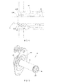
Figure 1 shows a perspective view of an embodiment of the vertical formwork according to the invention. -
Figure 2 shows a second perspective view of the vertical formwork ofFigure 1 . -
Figure 3 shows a front view of the vertical formwork ofFigure 1 . -
Figure 4 shows a section view of the vertical formwork ofFigure 1 . -
Figure 5 shows an exploded view of the vertical formwork ofFigure 1 . -
Figure 6 shows a perspective view of the front anchor of the vertical formwork ofFigure 1 . -
Figure 7 shows a section view of the front anchor ofFigure 6 . -
Figure 8 shows a perspective view of the sealing element of the front anchor ofFigure 6 . -
Figure 9 shows a section view of the sealing element of the anchor ofFigure 6 . -
Figure 10 shows a section view of the tubular extension of the front anchor ofFigure 6 . -
Figure 11 shows a detailed section view of the front anchor ofFigure 6 when it is fixed to the front formwork panel. -
Figure 12 shows a perspective view of the rear anchor of the vertical formwork ofFigure 1 . -
Figure 13 shows a section view of the rear anchor ofFigure 12 . -
Figure 14 shows a perspective view of the sealing element of the rear anchor ofFigure 12 . -
Figure 15 shows a section view of the sealing element of the rear anchor ofFigure 12 . -
Figure 16 shows a section view of the tubular extension of the rear anchor ofFigure 12 . -
Figure 17 shows a detailed section view of the rear anchor ofFigure 12 when it is fixed to the rear formwork panel. -
Figure 18 shows a section view of a formwork panel of the vertical formwork ofFigure 1 . -
Figures 1 to 5 show an embodiment of thevertical formwork 1 according to the invention. - The
vertical formwork 1 comprises twoformwork panels anchor formwork panels tie rod 6 fixed to theanchors formwork panels - In this embodiment, both
formwork panels formwork panels structure board structure bushing structure board board structure bushing formwork panels - The
vertical formwork 1 of this embodiment is a vertical formwork suitable for being adjusted from one face, i.e., thetie rod 6 can be fixed from one side of the formwork. In systems of this type one of the anchors, referred to asrear anchor 3, is fixed to one of the formwork panels, referred to asrear formwork panel 5, before theformwork panels formwork panels other anchor 2, referred to asfront anchor 2, and fixing thetie rod 6 to bothanchors tie rod 6 it located. Therefore, the formwork panel arranged on the side of the operator will be referred to as thefront formwork panel 4, and the formwork panel facing saidfront panel 4 will be referred to as therear formwork panel 5. Likewise, the anchor fixed to thefront formwork panel 4 will be referred to asfront anchor 2, and the anchor fixed to therear formwork panel 5 will be referred to as therear anchor 3. Furthermore, theinner face formwork panel outer face formwork panel inner face - In this embodiment, the
formwork panel 4, shown in detail inFigure 18 , comprises a housing extending from theouter face 44 to theinner face 43. The bushing 42 of theformwork panel 4 is arranged in said housing. Thebushing 42 forms a housing in which part of thecorresponding anchor 2 is housed. Thebushing 42 has aninlet opening 420 which is arranged flush with theouter face 44 of theformwork panel 4, and anoutlet opening 421 which is arranged flush with theinner face 43 of theformwork panel 4, the diameter of theoutlet opening 421 being smaller than the diameter of theinlet opening 420. The configuration of therear formwork panel 5 is the same as that of thefront formwork panel 4. - In other embodiments, depending on the dimensions of the formwork panel, each formwork panel can comprise a plurality of housings, a bushing and a respective anchor being arranged in each of them, such that two facing formwork panels can be fixed to one another through a plurality of tie rods fixed to said anchors.
- As discussed above, the
vertical formwork 1 comprises ananchor formwork panels Figures 6 and7 show thefront anchor 2 in detail, whereasFigures 12 and13 show therear anchor 3 in detail. Eachanchor housing tie rod 6 fixing theformwork panels - Each
anchor anchor formwork panel anchor tie rod 6 housed in thehousing anchor element anchor inner face formwork panel element anchor formwork panel anchor tie rod 6 housed in thehousing anchor - The sealing means of vertical formworks are elements which tend to deteriorate with use, and for this reason it is customary to have to change them. The fact that the sealing
element anchor formwork panel anchors formwork panels elements formwork panels formwork panels element anchor anchor element single sealing element - In this embodiment, each
anchor tubular extension respective sealing element tubular extension tubular extension outer fixing groove first end tubular extension element inner fixing ring inner fixing ring element outer fixing groove tubular extension element tubular extension element - Furthermore, in this embodiment to make it easier to assemble and disassemble the sealing
element tubular extension inner fixing ring - In this embodiment, the
tubular extension abutment ring outer fixing groove element inner housing inner fixing ring abutment ring tubular extension -
Figures 8 and9 show the sealingelement 23 of thefront anchor 2 in detail, whereasFigures 14 and15 show the sealingelement 33 of therear anchor 3 in detail. Arranging the sealingelement anchor formwork panel elements element - In this embodiment, both sealing
elements outer guiding ring element anchor outlet opening bushing formwork panel outer guiding ring element outlet opening anchor bushing - In this embodiment, both sealing
elements sealing ring outer wall ring formwork panel outer wall ring outlet opening respective bushing anchor bushing anchor formwork panel - In this embodiment, both sealing
elements end ring tie rod 6 housed in therespective anchor anchor tie rod 6. In the case of thefront anchor 2, the diameter of thetie rod 6 in contact with theend ring 236 of the sealingrubber 23 slightly varies depending on the width of the wall to be built, i.e., the distance left between the inner faces 43 and 53 of theformwork panels tie rod 6 in contact with theend ring 236 is cone-shaped. Therefore, theend ring 236 adapts to the variation in diameter of thetie rod 6 by sealing thefront anchor 2 with respect to thetie rod 6. - Furthermore, in this embodiment when the
tie rod 6 is housed in thehousing 34 of therear anchor 3, theend ring 336, due to the dimensions of thetie rod 6, tends to bend into the sealingelement 33. The sealingelement 33 comprises aninner gap 337 between theend ring 336 and thesealing ring 335 such that when thetie rod 6 is housed in theanchor 3, the part of theend ring 336 bent inwardly can be housed in saidinner gap 337. - In this embodiment, the
inner wall 335b of the sealingring 235 of the sealingelement 3 of therear anchor 3 is also supported against thetie rod 6, thereby achieving a double seal of thetie rod 6 with respect to therear anchor 3. - In this embodiment, when the
anchor formwork panel end ring bushing formwork panel ring bushing - In this embodiment, both sealing
elements first part inner fixing ring outer guiding ring sealing ring second part first part end ring - The
first part elements second part element element bushing - The sealing
element elements - In this embodiment, both the
front anchor 2 and therear anchor 3 comprise adome plate body body first part dome plate tubular extension first part - In this embodiment, the
body housing anchor housing 34 of therear anchor 3 is a threaded housing and is suitable for receiving a threaded end of thetie rod 6. Therefore, thetubular extension 32 of therear anchor 3 has a dual function, i.e., on one hand it helps fix the threaded end of thetie rod 6 to theanchor 3, and on the other it allows arranging the sealingelement 33 in the proximity of theinner face 53 of theformwork panel 5. Thehousing 24 of thefront anchor 2 is a non-threaded housing. Thetubular extension 22 of thefront anchor 2 has the function of arranging the sealingelement 23 in the proximity of theinner face 43 of theformwork panel 4. - As discussed above, the
first part body dome plate body outlet openings bushings formwork panels tie rod 6 is arranged in a slanted manner, the support wall of thebody dome plate element tubular extension first part body element tie rod 6 such that it deteriorates less than when the sealing element is arranged in the formwork panel, since in this situation if the tie rod is arranged in a slanted manner with respect to the axis of the sealing element, said sealing element deteriorates more. - In this embodiment, the
dome plate anchor outer face formwork panel dome plate structure formwork panel anchor formwork panel
Claims (13)
- Anchor for a vertical formwork, the vertical formwork comprising two formwork panels (4, 5) facing one another and the anchor (2, 3) being suitable for being fixed to one of the formwork panels (4, 5), the anchor (2, 3) comprising- a housing (24, 34) for receiving a part of a tie rod (6) fixing the two formwork panels (4, 5), and- sealing means configured for sealing the anchor (2, 3) with respect to the formwork panel (4, 5) in which it is fixed and with respect to the tie rod (6) housed in the housing (24, 34) of the anchor (2, 3),characterized in that- the sealing means comprise a sealing element (23, 33) which is arranged at one end of the anchor (2, 3) and which is configured for sealing, when the anchor (2, 3) is fixed to the respective formwork panel (4, 5), both the anchor (2, 3) with respect to the formwork panel (4, 5) in which it is fixed and the anchor (2, 3) with respect to the tie rod (6) housed in the housing (24, 34) of the anchor (2, 3).
- Anchor according to claim 1, comprising a tubular extension (22, 32), the sealing element (23, 33) being arranged at one end (222, 322) of said tubular extension (22, 32).
- Anchor according to claim 2, wherein the tubular extension (22, 32) comprises an outer fixing groove (220, 320) which is arranged in the proximity of the end (222, 322) of the tubular extension (22, 32), and the sealing element (23, 33) comprises an inner fixing ring (232, 332) at one of its ends, said inner fixing ring (232, 332) of the sealing element (23, 33) being housed in the outer fixing groove (220, 320) of the tubular extension (22, 32).
- Anchor according to any of the preceding claims, wherein the sealing element (23, 33) comprises an outer guiding ring (234, 334) diametrically projecting with respect to the rest of the sealing element (23, 33) and configured for guiding the anchor (2, 3) to the outlet opening (421) of the formwork panel (4, 5) in which it is fixed.
- Anchor according to any of the preceding claims, wherein the sealing element (23, 33) comprises a sealing ring (235, 335) the outer wall of which is supported against the formwork panel (4, 5) in which it is fixed.
- Anchor according to claim 5, wherein when the anchor (2, 3) is fixed to the respective formwork panel (4, 5), an inner wall of the sealing ring (335) is supported against the tie rod (6).
- Anchor according to any of the preceding claims, wherein the sealing element (23, 33) comprises an end ring (236, 336) which is supported against the tie rod (6) housed in the anchor (2, 3) when the anchor (2, 3) is fixed to the respective formwork panel (4, 5), such that the anchor (2, 3) is sealed with respect to the tie rod (6).
- Anchor according to any of the preceding claims, wherein the sealing element (23, 33) is a rubber gasket.
- Anchor according to claim 2, wherein the sealing element (23, 33) comprises- a first part (230, 330) comprising▪ an inner fixing ring (232, 332) suitable for being housed in an outer fixing groove (220, 320) of the tubular extension (22, 32),▪ an outer guiding ring (234, 334) diametrically projecting with respect to the rest of the sealing element (23, 33) and configured for guiding the anchor (2, 3) to the outlet opening (421) of the formwork panel (4, 5) in which it is fixed, and▪ a sealing ring (235, 335) the outer wall of which is supported against the formwork panel (4, 5) in which it is fixed, and- a second part (231, 331) after the first part (230, 330) comprising▪ an end ring (236, 336) which is supported against the tie rod (6) housed in the anchor (2, 3) when the anchor (2, 3) is fixed to the respective formwork panel (4, 5),- the first part (230, 330) of the sealing element (23, 33) being harder than the second part (231, 331) of the sealing element (23, 33).
- Anchor according to claim 9, wherein the sealing element (23, 33) is a rubber gasket made by injecting two materials having a different hardness.
- Anchor according to any of the preceding claims, comprising a dome plate (20, 30) comprising a spherical part with an opening (200, 300), and a body (21, 31) which is arranged in said opening (200, 300), the body (21, 31) comprising a first part (210, 310) coupled to the dome plate (200, 300) like a ball and socket joint, and the end at which the sealing element (23, 33) is arranged after said first part (210, 310).
- Anchor according to any of the preceding claims, wherein part of the sealing element (23, 33) projects from the respective formwork panel (4, 5) when the anchor (2, 3) is fixed to the respective formwork panel (4, 5).
- Vertical formwork comprising at least- two formwork panels (4, 5) arranged facing one another,- an anchor (2, 3) according to any of the preceding claims fixed to each of said formwork panels (4, 5), and- a tie rod (6) fixed to the anchor (2, 3) of each of the formwork panels (4, 5).
Priority Applications (11)
| Application Number | Priority Date | Filing Date | Title |
|---|---|---|---|
| EP16382280.2A EP3258032A1 (en) | 2016-06-17 | 2016-06-17 | Anchor for a vertical formwork and vertical formwork |
| PCT/EP2017/064791 WO2017216355A1 (en) | 2016-06-17 | 2017-06-16 | Anchor for a vertical formwork and vertical formwork |
| PL17732064.5T PL3472407T3 (en) | 2016-06-17 | 2017-06-16 | Vertical formwork |
| EP17732064.5A EP3472407B1 (en) | 2016-06-17 | 2017-06-16 | Vertical formwork |
| FIEP17732064.5T FI3472407T3 (en) | 2016-06-17 | 2017-06-16 | Vertical formwork |
| DK17732064.5T DK3472407T3 (en) | 2016-06-17 | 2017-06-16 | VERTICAL FORMWORK |
| CA3028018A CA3028018C (en) | 2016-06-17 | 2017-06-16 | Anchor for a vertical formwork and vertical formwork |
| ES17732064T ES2936468T3 (en) | 2016-06-17 | 2017-06-16 | vertical formwork |
| CN201780037375.7A CN109415908B (en) | 2016-06-17 | 2017-06-16 | Anchor for a vertical formwork and vertical formwork |
| US16/217,549 US10815683B2 (en) | 2016-06-17 | 2018-12-12 | Vertical formwork with tie rod and tie rod anchor |
| US17/030,771 US11359391B2 (en) | 2016-06-17 | 2020-09-24 | Anchor with sealing element for a vertical formwork |
Applications Claiming Priority (1)
| Application Number | Priority Date | Filing Date | Title |
|---|---|---|---|
| EP16382280.2A EP3258032A1 (en) | 2016-06-17 | 2016-06-17 | Anchor for a vertical formwork and vertical formwork |
Publications (1)
| Publication Number | Publication Date |
|---|---|
| EP3258032A1 true EP3258032A1 (en) | 2017-12-20 |
Family
ID=56511503
Family Applications (2)
| Application Number | Title | Priority Date | Filing Date |
|---|---|---|---|
| EP16382280.2A Withdrawn EP3258032A1 (en) | 2016-06-17 | 2016-06-17 | Anchor for a vertical formwork and vertical formwork |
| EP17732064.5A Active EP3472407B1 (en) | 2016-06-17 | 2017-06-16 | Vertical formwork |
Family Applications After (1)
| Application Number | Title | Priority Date | Filing Date |
|---|---|---|---|
| EP17732064.5A Active EP3472407B1 (en) | 2016-06-17 | 2017-06-16 | Vertical formwork |
Country Status (9)
| Country | Link |
|---|---|
| US (2) | US10815683B2 (en) |
| EP (2) | EP3258032A1 (en) |
| CN (1) | CN109415908B (en) |
| CA (1) | CA3028018C (en) |
| DK (1) | DK3472407T3 (en) |
| ES (1) | ES2936468T3 (en) |
| FI (1) | FI3472407T3 (en) |
| PL (1) | PL3472407T3 (en) |
| WO (1) | WO2017216355A1 (en) |
Cited By (2)
| Publication number | Priority date | Publication date | Assignee | Title |
|---|---|---|---|---|
| EP3653810A1 (en) * | 2018-11-15 | 2020-05-20 | DOKA GmbH | Formwork panel, formwork system and method for mounting a tie rod |
| US20220259872A1 (en) * | 2019-07-31 | 2022-08-18 | Meva Schalungs-Systeme Gmbh | Formwork tie |
Families Citing this family (5)
| Publication number | Priority date | Publication date | Assignee | Title |
|---|---|---|---|---|
| ES2899357T3 (en) * | 2018-06-22 | 2022-03-11 | Ulma C Y E S Coop | vertical formwork |
| IT201900005054A1 (en) * | 2019-04-04 | 2020-10-04 | Faresin Formwork S P A | DEVICE FOR POSITIONING AND SEALING A TIE ROD INSIDE A PROFILE OF A FORMWORK PANEL FOR VERTICAL CASTINGS |
| WO2020201857A1 (en) * | 2019-04-04 | 2020-10-08 | Faresin Formwork S.p.A. | Device for the positioning and retention of a tension member within a profile of a vertical casting formwork panel |
| DE102020101188A1 (en) * | 2020-01-20 | 2021-07-22 | Peri Gmbh | Framed formwork element |
| EP4685312A1 (en) * | 2023-03-22 | 2026-01-28 | Encofrados J.Alsina S.A. | Device for the positioning of formwork panels for the construction of a concrete wall |
Citations (5)
| Publication number | Priority date | Publication date | Assignee | Title |
|---|---|---|---|---|
| KR20080001412U (en) * | 2006-11-24 | 2008-05-28 | 주식회사 풍양정밀 | Form-Tie for Inserts |
| WO2008089442A2 (en) | 2007-01-18 | 2008-07-24 | Western Forms, Inc. | Lightweight crane-set forming panel |
| EP2126248A1 (en) | 2007-01-27 | 2009-12-02 | Peri GmbH | Anchor system of a concrete wall form |
| EP2816175A1 (en) | 2013-06-19 | 2014-12-24 | DOKA GmbH | Shuttering tie holder, shuttering tie as well as shuttering element for receiving the same |
| KR101497688B1 (en) * | 2014-02-02 | 2015-03-12 | 이옥순 | Fixing device for maintain a distance and anchor bolt of mould |
Family Cites Families (38)
| Publication number | Priority date | Publication date | Assignee | Title |
|---|---|---|---|---|
| US915995A (en) * | 1908-05-16 | 1909-03-23 | Charles C Mccarty | Manufacture of concrete walls. |
| US1808912A (en) * | 1928-07-07 | 1931-06-09 | Willard John Melville | Art of and means for molding concrete structures |
| US1935218A (en) * | 1931-02-23 | 1933-11-14 | Universal Form Clamp Co | Form tie for wall structures |
| US2014080A (en) * | 1934-03-16 | 1935-09-10 | Samuel S Colt | Concrete form retaining means |
| US2270035A (en) * | 1940-11-08 | 1942-01-13 | Samule S Colt | Retaining means for concrete form walls |
| US3328055A (en) * | 1965-06-07 | 1967-06-27 | Kalman J Lang | Conduit grip and process |
| DE1684261A1 (en) * | 1966-06-01 | 1971-03-04 | Walter Hoff | Device for building concrete formwork or the like. |
| FR1547267A (en) * | 1966-12-27 | 1968-11-22 | Clamping device, in particular for concrete formwork or the like | |
| US3490730A (en) * | 1967-10-11 | 1970-01-20 | Gates & Sons | Combination form tie grout plug and deformable spacer |
| US3618887A (en) * | 1969-04-23 | 1971-11-09 | Superior Concrete Accessories | Concrete wall form and particular elastomeric tie rod bushing therefor |
| US3801061A (en) * | 1969-04-30 | 1974-04-02 | Burke Concrete Accessories | Form panel with grouting plug core |
| US3633867A (en) * | 1969-08-08 | 1972-01-11 | Superior Concrete Accessories | She-bolt and torque wrench assembly |
| US3676031A (en) * | 1970-05-28 | 1972-07-11 | Conenco Intern Ltd | Post-tensioning system |
| US3905093A (en) * | 1970-07-30 | 1975-09-16 | Chester I Williams | Method of erecting wall-form |
| US3690613A (en) * | 1970-10-08 | 1972-09-12 | Symons Corp | Concrete wall form installation with particular tie rod securing means therefor |
| US3907244A (en) * | 1973-05-04 | 1975-09-23 | Clyde H Abbott | Tie rod with expansible cone seal members |
| US3918673A (en) * | 1973-07-23 | 1975-11-11 | Clyde H Abbott | Rod with wall form sealing and spacing means |
| US3927857A (en) * | 1974-07-08 | 1975-12-23 | Peter R Lovisa | Reusable tie assembly for concrete forms |
| US4159099A (en) * | 1977-05-09 | 1979-06-26 | Maguire James V | Sleeve assembly for forming openings in molded structures |
| DE3445746A1 (en) * | 1984-12-14 | 1986-06-19 | Emil Steidle Gmbh & Co, 7480 Sigmaringen | Seal for clamping-anchor through-holes |
| US5537797A (en) * | 1993-11-22 | 1996-07-23 | The Salk Institute For Biological Studies | Modular concrete form system and method for constructing concrete walls |
| US5497592A (en) * | 1994-05-19 | 1996-03-12 | Boeshart; Patrick E. | Quick release tie |
| JP2750846B2 (en) * | 1995-08-30 | 1998-05-13 | 義行 早川 | Concrete formwork facing distance fixing fixture |
| WO2001055531A1 (en) * | 2000-01-28 | 2001-08-02 | Toray Industries,Inc. | Auxiliary tool for fixing wall material, and its production method, and method for producing concrete structure using the auxiliary tool for fixing wall material |
| US7124547B2 (en) * | 2002-08-26 | 2006-10-24 | Bravinski Leonid G | 3-D construction modules |
| US6935607B2 (en) * | 2002-10-23 | 2005-08-30 | Western Forms, Inc. | Forming panel with extruded elongated threaded slot for receiving threaded attachment members |
| ATE497564T1 (en) * | 2007-03-09 | 2011-02-15 | Carlo Cuttitta | SHELL ELEMENT, FORMWORK, SYSTEM FOR CASTING AND TREATING CONSTRUCTION ELEMENTS, AND METHOD FOR THEIR PRODUCTION |
| KR20100006679U (en) * | 2008-12-22 | 2010-07-01 | 미래테크(주) | Combination a mold |
| CN201521106U (en) * | 2009-08-21 | 2010-07-07 | 中国建筑第八工程局有限公司 | Concrete casting device with seal rings |
| DE102010002108A1 (en) * | 2010-02-18 | 2011-08-18 | Peri GmbH, 89264 | Anchor system of a concrete wall formwork |
| JP3161312U (en) * | 2010-05-07 | 2010-07-29 | 麗梅 林 | Surface treatment-free formwork fixing device structure |
| ITVI20100233A1 (en) * | 2010-08-11 | 2012-02-12 | Legnotre Ind Spa | MODULAR SYSTEM FOR THE COMPOSITION OF A FORMWORK PANEL |
| JPWO2012020519A1 (en) * | 2010-08-11 | 2013-10-28 | 中日本ハイウェイ・エンジニアリング名古屋株式会社 | Cone for fixing concrete formwork |
| DE102012212603A1 (en) * | 2012-07-18 | 2014-01-23 | Harsco Infrastructure Services Gmbh | Locking device with wall formwork fastening device and method |
| EP3156561A1 (en) * | 2015-07-03 | 2017-04-19 | MEVA Schalungs-Systeme GmbH | Frame formwork element |
| EP3181781A1 (en) * | 2015-12-18 | 2017-06-21 | DOKA GmbH | Formwork anchor holder |
| AT519100B1 (en) * | 2016-11-16 | 2018-04-15 | Ringer Kg | Device for receiving a formwork anchor in a formwork element of a concrete wall formwork |
| CA3048288A1 (en) * | 2017-01-27 | 2018-08-02 | Meva Schalungs-Systeme Gmbh | Sealing a lead-through of an anchor rod through a panel formwork element |
-
2016
- 2016-06-17 EP EP16382280.2A patent/EP3258032A1/en not_active Withdrawn
-
2017
- 2017-06-16 CA CA3028018A patent/CA3028018C/en active Active
- 2017-06-16 FI FIEP17732064.5T patent/FI3472407T3/en active
- 2017-06-16 CN CN201780037375.7A patent/CN109415908B/en active Active
- 2017-06-16 ES ES17732064T patent/ES2936468T3/en active Active
- 2017-06-16 PL PL17732064.5T patent/PL3472407T3/en unknown
- 2017-06-16 WO PCT/EP2017/064791 patent/WO2017216355A1/en not_active Ceased
- 2017-06-16 DK DK17732064.5T patent/DK3472407T3/en active
- 2017-06-16 EP EP17732064.5A patent/EP3472407B1/en active Active
-
2018
- 2018-12-12 US US16/217,549 patent/US10815683B2/en active Active
-
2020
- 2020-09-24 US US17/030,771 patent/US11359391B2/en active Active
Patent Citations (5)
| Publication number | Priority date | Publication date | Assignee | Title |
|---|---|---|---|---|
| KR20080001412U (en) * | 2006-11-24 | 2008-05-28 | 주식회사 풍양정밀 | Form-Tie for Inserts |
| WO2008089442A2 (en) | 2007-01-18 | 2008-07-24 | Western Forms, Inc. | Lightweight crane-set forming panel |
| EP2126248A1 (en) | 2007-01-27 | 2009-12-02 | Peri GmbH | Anchor system of a concrete wall form |
| EP2816175A1 (en) | 2013-06-19 | 2014-12-24 | DOKA GmbH | Shuttering tie holder, shuttering tie as well as shuttering element for receiving the same |
| KR101497688B1 (en) * | 2014-02-02 | 2015-03-12 | 이옥순 | Fixing device for maintain a distance and anchor bolt of mould |
Cited By (4)
| Publication number | Priority date | Publication date | Assignee | Title |
|---|---|---|---|---|
| EP3653810A1 (en) * | 2018-11-15 | 2020-05-20 | DOKA GmbH | Formwork panel, formwork system and method for mounting a tie rod |
| US11199013B2 (en) | 2018-11-15 | 2021-12-14 | Doka Gmbh | Formwork panel, formwork system and method for mounting a tie rod |
| US11725404B2 (en) | 2018-11-15 | 2023-08-15 | Doka Gmbh | Formwork panel, formwork system and method for mounting a tie rod |
| US20220259872A1 (en) * | 2019-07-31 | 2022-08-18 | Meva Schalungs-Systeme Gmbh | Formwork tie |
Also Published As
| Publication number | Publication date |
|---|---|
| CN109415908B (en) | 2021-07-13 |
| PL3472407T3 (en) | 2023-02-20 |
| US10815683B2 (en) | 2020-10-27 |
| CA3028018C (en) | 2023-10-24 |
| US20210040753A1 (en) | 2021-02-11 |
| EP3472407A1 (en) | 2019-04-24 |
| US11359391B2 (en) | 2022-06-14 |
| CA3028018A1 (en) | 2017-12-21 |
| WO2017216355A1 (en) | 2017-12-21 |
| FI3472407T3 (en) | 2023-01-31 |
| ES2936468T3 (en) | 2023-03-17 |
| US20190112826A1 (en) | 2019-04-18 |
| EP3472407B1 (en) | 2022-10-19 |
| DK3472407T3 (en) | 2023-01-23 |
| CN109415908A (en) | 2019-03-01 |
Similar Documents
| Publication | Publication Date | Title |
|---|---|---|
| EP3472407B1 (en) | Vertical formwork | |
| EP3587705B1 (en) | Vertical formwork | |
| KR101423922B1 (en) | Coupler | |
| CN101796301A (en) | Eccentric screw pump with split stator | |
| EP3258033A1 (en) | Anchor for a vertical formwork and vertical formwork | |
| KR101612918B1 (en) | Formwork binding equipment for the construction of a building pillar | |
| CN110475938B (en) | Anchors and Vertical Formwork for Vertical Formwork | |
| WO2014048937A1 (en) | Wall formwork with a sealing system | |
| JP4909252B2 (en) | Rebar connection seal structure and rebar connection device | |
| KR102565226B1 (en) | One-touch type reinforced coupler | |
| JP5946089B2 (en) | Tunnel inner winding reinforcement method | |
| JP2017043884A (en) | Joint structure of segment | |
| CN107268896A (en) | A kind of grout sleeve for bar connecting | |
| KR101958142B1 (en) | A connecter of concrete elements | |
| JP5718652B2 (en) | Reinforcing bar seal structure | |
| KR20130081936A (en) | Sleeve for rebar connection | |
| JP7005952B2 (en) | segment | |
| JP5495962B2 (en) | Mechanical rebar joint and reinforcement structure with shear reinforcement support function | |
| KR20090004113U (en) | Formwork for Formwork for Corner Walls | |
| KR20160087108A (en) | Steel concrete structure withe detachable connections between steel plate and concrete | |
| EP3839160A1 (en) | Coupling device for a toilet tank flushing device | |
| JP2021188453A (en) | Plug for sleeve fittings | |
| JP2013238037A (en) | Reinforcement joint and precast concrete member | |
| EP4685312A1 (en) | Device for the positioning of formwork panels for the construction of a concrete wall | |
| JP2018115443A (en) | Ring joint structure for connecting steel segments and method for connecting the same |
Legal Events
| Date | Code | Title | Description |
|---|---|---|---|
| PUAI | Public reference made under article 153(3) epc to a published international application that has entered the european phase |
Free format text: ORIGINAL CODE: 0009012 |
|
| AK | Designated contracting states |
Kind code of ref document: A1 Designated state(s): AL AT BE BG CH CY CZ DE DK EE ES FI FR GB GR HR HU IE IS IT LI LT LU LV MC MK MT NL NO PL PT RO RS SE SI SK SM TR |
|
| AX | Request for extension of the european patent |
Extension state: BA ME |
|
| STAA | Information on the status of an ep patent application or granted ep patent |
Free format text: STATUS: THE APPLICATION IS DEEMED TO BE WITHDRAWN |
|
| 18D | Application deemed to be withdrawn |
Effective date: 20180621 |