EP3258017A1 - Work vehicle - Google Patents
Work vehicle Download PDFInfo
- Publication number
- EP3258017A1 EP3258017A1 EP15907301.4A EP15907301A EP3258017A1 EP 3258017 A1 EP3258017 A1 EP 3258017A1 EP 15907301 A EP15907301 A EP 15907301A EP 3258017 A1 EP3258017 A1 EP 3258017A1
- Authority
- EP
- European Patent Office
- Prior art keywords
- console box
- disposed
- operating position
- rotational axis
- work vehicle
- Prior art date
- Legal status (The legal status is an assumption and is not a legal conclusion. Google has not performed a legal analysis and makes no representation as to the accuracy of the status listed.)
- Granted
Links
- 230000005540 biological transmission Effects 0.000 claims description 27
- 239000012530 fluid Substances 0.000 claims description 6
- 230000033001 locomotion Effects 0.000 description 2
- 238000005452 bending Methods 0.000 description 1
- 230000007423 decrease Effects 0.000 description 1
- 238000010586 diagram Methods 0.000 description 1
- 230000000694 effects Effects 0.000 description 1
- 230000004048 modification Effects 0.000 description 1
- 238000012986 modification Methods 0.000 description 1
Images


Classifications
-
- E—FIXED CONSTRUCTIONS
- E02—HYDRAULIC ENGINEERING; FOUNDATIONS; SOIL SHIFTING
- E02F—DREDGING; SOIL-SHIFTING
- E02F9/00—Component parts of dredgers or soil-shifting machines, not restricted to one of the kinds covered by groups E02F3/00 - E02F7/00
- E02F9/16—Cabins, platforms, or the like, for drivers
-
- B—PERFORMING OPERATIONS; TRANSPORTING
- B60—VEHICLES IN GENERAL
- B60N—SEATS SPECIALLY ADAPTED FOR VEHICLES; VEHICLE PASSENGER ACCOMMODATION NOT OTHERWISE PROVIDED FOR
- B60N2/00—Seats specially adapted for vehicles; Arrangement or mounting of seats in vehicles
- B60N2/24—Seats specially adapted for vehicles; Arrangement or mounting of seats in vehicles for particular purposes or particular vehicles
-
- B—PERFORMING OPERATIONS; TRANSPORTING
- B60—VEHICLES IN GENERAL
- B60N—SEATS SPECIALLY ADAPTED FOR VEHICLES; VEHICLE PASSENGER ACCOMMODATION NOT OTHERWISE PROVIDED FOR
- B60N2/00—Seats specially adapted for vehicles; Arrangement or mounting of seats in vehicles
- B60N2/75—Arm-rests
- B60N2/753—Arm-rests movable to an inoperative position
-
- B—PERFORMING OPERATIONS; TRANSPORTING
- B60—VEHICLES IN GENERAL
- B60N—SEATS SPECIALLY ADAPTED FOR VEHICLES; VEHICLE PASSENGER ACCOMMODATION NOT OTHERWISE PROVIDED FOR
- B60N2/00—Seats specially adapted for vehicles; Arrangement or mounting of seats in vehicles
- B60N2/75—Arm-rests
- B60N2/79—Adaptations for additional use of the arm-rests
- B60N2/797—Adaptations for additional use of the arm-rests for use as electrical control means, e.g. switches
-
- B—PERFORMING OPERATIONS; TRANSPORTING
- B60—VEHICLES IN GENERAL
- B60R—VEHICLES, VEHICLE FITTINGS, OR VEHICLE PARTS, NOT OTHERWISE PROVIDED FOR
- B60R7/00—Stowing or holding appliances inside vehicle primarily intended for personal property smaller than suit-cases, e.g. travelling articles, or maps
- B60R7/04—Stowing or holding appliances inside vehicle primarily intended for personal property smaller than suit-cases, e.g. travelling articles, or maps in driver or passenger space, e.g. using racks
-
- B—PERFORMING OPERATIONS; TRANSPORTING
- B62—LAND VEHICLES FOR TRAVELLING OTHERWISE THAN ON RAILS
- B62D—MOTOR VEHICLES; TRAILERS
- B62D1/00—Steering controls, i.e. means for initiating a change of direction of the vehicle
- B62D1/02—Steering controls, i.e. means for initiating a change of direction of the vehicle vehicle-mounted
- B62D1/16—Steering columns
- B62D1/18—Steering columns yieldable or adjustable, e.g. tiltable
-
- B—PERFORMING OPERATIONS; TRANSPORTING
- B62—LAND VEHICLES FOR TRAVELLING OTHERWISE THAN ON RAILS
- B62D—MOTOR VEHICLES; TRAILERS
- B62D1/00—Steering controls, i.e. means for initiating a change of direction of the vehicle
- B62D1/02—Steering controls, i.e. means for initiating a change of direction of the vehicle vehicle-mounted
- B62D1/22—Alternative steering-control elements, e.g. for teaching purposes
-
- B—PERFORMING OPERATIONS; TRANSPORTING
- B62—LAND VEHICLES FOR TRAVELLING OTHERWISE THAN ON RAILS
- B62D—MOTOR VEHICLES; TRAILERS
- B62D12/00—Steering specially adapted for vehicles operating in tandem or having pivotally connected frames
-
- E—FIXED CONSTRUCTIONS
- E02—HYDRAULIC ENGINEERING; FOUNDATIONS; SOIL SHIFTING
- E02F—DREDGING; SOIL-SHIFTING
- E02F9/00—Component parts of dredgers or soil-shifting machines, not restricted to one of the kinds covered by groups E02F3/00 - E02F7/00
- E02F9/20—Drives; Control devices
- E02F9/2004—Control mechanisms, e.g. control levers
-
- F—MECHANICAL ENGINEERING; LIGHTING; HEATING; WEAPONS; BLASTING
- F16—ENGINEERING ELEMENTS AND UNITS; GENERAL MEASURES FOR PRODUCING AND MAINTAINING EFFECTIVE FUNCTIONING OF MACHINES OR INSTALLATIONS; THERMAL INSULATION IN GENERAL
- F16G—BELTS, CABLES, OR ROPES, PREDOMINANTLY USED FOR DRIVING PURPOSES; CHAINS; FITTINGS PREDOMINANTLY USED THEREFOR
- F16G13/00—Chains
- F16G13/12—Hauling- or hoisting-chains so called ornamental chains
- F16G13/16—Hauling- or hoisting-chains so called ornamental chains with arrangements for holding electric cables, hoses, or the like
Definitions
- the present invention relates to a work vehicle.
- the operator gets in and out of the vehicle with the console box moved to the rear side.
- Patent Literature 1 2012-127137
- console box far to the rear to facilitate operator ingress and egress, but if the inner wall of the cab is located just behind the operator's seat, the console box can be slid back only a small amount, so it is still difficult for the operator to get in and out.
- the work vehicle pertaining to the first invention comprises a console box and a support.
- the console box is disposed to the side of an operator's seat and is configured to be rotatable in the forth and back direction.
- the support has a rotational axis disposed in the left and right direction below the console box, and rotatably supports the console box around the rotational axis and between an operating position in which the console box is horizontally disposed and a retracted position in which the console box is inclined at a position where the console box has been rotated rearward from the operating position.
- the spacing in the horizontal direction between the front and rear ends of the console box disposed in the retracted position is less than the spacing in the horizontal direction between the front and rear ends of the console box disposed in the operating position.
- the work vehicle pertaining to the second invention is the work vehicle pertaining to the first invention, wherein the rotational axis is disposed ahead of the center in the forth and back direction of the console box disposed in the operating position.
- the work vehicle pertaining to the third invention is the work vehicle pertaining to the first or second invention, further comprising an operation member and a transmission component.
- the operation member is disposed on the upper side near the front end of the console box.
- the transmission component is disposed facing the floor of the operator's seat from the lower side near the front end of the console box, and transmits the operation of the operation member to an operational object to be operated.
- the transmission component telescopes in and out along with rotation of the console box from the operating position to the retracted position, while rotating with its end on the floor side acting as the fulcrum.
- console box connected to the transmission component for transmitting the operation of the operation member can be rotated to the rear.
- the transmission component and the rotational axis are both disposed toward the front of the console box, so there will be less change in the length of the transmission component accompanying rotation of the console box.
- the position of the rotational axis of the console box is not the same as the position of the end serving as the rotational fulcrum of the transmission component in side view, when the transmission component rotates along with the rotation of the console box, the length of the transmission component changes.
- both the transmission component and the rotational axis are disposed near the front of the console box, the amount of rotation of the transmission component accompanying rotation of the console box is reduced, so the change in the length of the transmission component can also be suppressed.
- the work vehicle pertaining to the fourth invention is the work vehicle pertaining to the third invention, wherein the rotational axis is disposed within the rotation range of the transmission component in side view.
- the work vehicle pertaining to the fifth invention is the work vehicle pertaining to the third invention, wherein, in a state in which the console box is disposed in the operating position, the transmission component is disposed ahead of the rotational axis.
- the work vehicle pertaining to the sixth invention is the work vehicle pertaining to the third invention, comprising a front frame, a rear frame, a hydraulic actuator, and a control valve.
- the hydraulic actuator is disposed from the front frame to the rear frame and changes the steering angle of the front frame with respect to the rear frame.
- the control valve controls the fluid supplied to the hydraulic actuator.
- the operation member is a joystick lever.
- the operational object is the control valve.
- a console box provided with a joystick lever for controlling the steering angle can be rotated so that its front end moves far to the rear.
- the present invention provides a work vehicle that is easier to get in and out of.
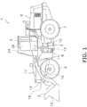
- FIG. 1 is a simplified diagram of the configuration of a wheel loader 1 in this embodiment.
- the wheel loader 1 in this embodiment mainly comprises a body frame 2, a work implement 3, a pair of front tires 4, a cab 5, an engine compartment 6, a pair of rear tires 7, and a pair of steering cylinders 8.
- the front, back, left, and right directions mean those directions as viewed by an operator seated in an operator's seat 30 (discussed below) in the cab 5.
- the wheel loader 1 performs earth loading work and the like with the work implement 3.
- the body frame 2 is what is known as an articulated type, and has a front frame 11, a rear frame 12, and a linking shaft 13.
- the front frame 11 is disposed in front of the rear frame 12.
- the linking shaft 13 is provided in the center of the vehicle width direction, and pivotably links the front frame 11 to the rear frame 12.
- the front tires 4 are attached on the left and right sides of the front frame 11.
- the rear tires 7 are attached on the left and right sides of the rear frame 12.
- the work implement 3 is driven by hydraulic fluid from a work implement pump (not shown).
- the work implement 3 has a boom 14, a bucket 15, a lift cylinder 16, and a bucket cylinder 17.
- the boom 14 is mounted on the front frame 11.
- the bucket 15 is attached to the distal end of the boom 14.
- the lift cylinder 16 and the bucket cylinder 17 are hydraulic cylinders. One end of the lift cylinder 16 is attached to the front frame 11, and the other end of the lift cylinder 16 is attached to the boom 14. The lift cylinder 16 telescopes in and out to pivot the boom 14 up and down. One end of the bucket cylinder 17 is attached to the front frame 11, and the other end of the bucket cylinder 17 is attached to the bucket 15 via a bell crank 18. The bucket cylinder 17 telescopes in and out to pivot the bucket 15 up and down.
- the steering cylinders 8 are disposed on the left and right sides in the vehicle width direction of the linking shaft 13, and are each attached from the front frame 11 to the rear frame 12. The flow of fluid supplied to the pair of steering cylinders 8 is changed to change the steering angle of the front frame 11 with respect to the rear frame 12 and to change the travel direction of the wheel loader 1.
- the cab 5 is mounted on the rear frame 12, inside of which are disposed a steering wheel 37 or joystick lever 32 (discussed below; see FIG. 2 ) for steering, a lever for controlling the work implement 3, various display devices, and so forth.
- the engine compartment 6 is disposed on the rear frame 12 to the rear of the cab 5, and houses an engine.
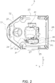
- FIG. 2 is a top view of the cab 5.
- FIG. 3 is a partial side view of the cab 5.
- the cab 5 has a substantially hexagonal shape in top view, and has a front face 21, a right inclined face 22, a right side face 23, a left inclined face 24, a left side face 25, and a rear face 26.
- the front face 21 and the rear face 26 are parallel to each other and are each disposed along the left and right direction (see arrow Y in FIG. 2 ).
- the right side face 23 is disposed facing forward from the right end of the rear face 26.
- the right inclined face 22 is inclined with respect to the forth and back direction (see arrow X in FIG.
- the left side face 25 is disposed facing forward from the left end of the rear face 26.
- the left inclined face 24 is inclined with respect to the forth and back direction and is provided between the front end of the left side face 25 and the left end of the front face 21.
- the right inclined face 22 and the left inclined face 24 are disposed so that their spacing decreases toward the front.
- the right inclined face 22 and the left inclined face 24 are inclined in the forth and back direction in order to avoid interference with the front frame during steering.
- a door opening 27 is formed at a position in front of the left side face 25, and the door 28 shown in FIG. 1 is provided to the door opening 27.
- FIG. 4a shows the state when the left side face 25 has been removed from FIG. 3 .
- the operator's seat 30, a console box 31, a joystick lever 32, a link 33, an armrest 34, a support 35, a rotation lever 36, the steering wheel 37 (see FIG. 2 ), and so forth are provided inside the cab 5.
- the operator's seat 30 is disposed in the approximate center between the right side face 23 and the left side face 25.
- the operator's seat 30 is disposed at a position roughly facing the door opening 27.
- the operator's seat 30 has a backrest 30a, a seat bottom 30b, a lower frame 30c (discussed below; see FIG. 5 ) on the lower side of the seat bottom 30b, and so forth, and springs (not shown) are disposed on the lower side of the lower frame 30c.
- the steering wheel 37 is operated by the operator when changing the steering angle of the front frame 11 with respect to the rear frame 12 during movement, for example. As shown in FIG. 2 , the steering wheel 37 is disposed in front of the operator's seat 30 and between the right inclined face 22 and the left inclined face 24.
- the console box 31 is disposed on the left lateral side of the operator's seat 30.
- the console box 31 can also be said to be disposed between the operator's seat 30 and the door opening 27.
- the console box 31 is formed longer in the forth and back direction, and is disposed substantially horizontally.
- a linking member (not shown) for linking the joystick lever 32 and the link 33 (discussed below) and the like are provided inside the console box 31.
- the position of the console box 31 disposed so as to be substantially horizontal as shown in FIG. 4a is an operating position P1.
- the operating position P1 is the position of the console box 31 when the operator is seated in the operator's seat 30 and operating the joystick lever 32.
- the joystick lever 32 is provided on the upper side near the front end 31a of the console box 31 so as to protrude upward.
- the joystick lever 32 is used during work such as loading and conveying earth.
- the steering angle of the front frame 11 with respect to the rear frame 12 is changed by rotating the joystick lever 32 in the left and right direction.
- the link 33 is a universal joint, and as shown in FIG. 4a includes a first joint 41, a second joint 42, and a telescoping part 43.
- the first joint 41 and the second joint 42 are disposed at both ends of the telescoping part 43.
- the telescoping part 43 is made up of an outer tube 43a and an inner tube 43b, and the outer tube 43a and the inner tube 43b are spline-coupled.
- FIG. 4b is a cross section along the EE' line in FIG. 4a .
- tooth-like grooves are formed on the inner periphery of the outer tube 43a
- tooth-like grooves that mate with the tooth-like grooves in the outer tube 43a are formed on the outer periphery of the inner tube 43b.
- the grooves are formed along the lengthwise direction.
- the first joint 41 is attached to the lower side of the console box 31 and is linked to the joystick lever 32 by a linking member (not shown).
- the second joint 42 is inserted into and attached to the floor 5 a of the cab 5.
- the link 33 is covered with a cover C (see the dotted line).
- the second joint 42 of the link 33 is connected to a pilot valve 19 as shown in FIG. 3 .
- the operation of the joystick lever 32 is transmitted to the pilot valve 19 via the link 33, and the pilot pressure inputted to a steering valve 20 is adjusted.
- the steering valve 20 adjusts the flow of the fluid supplied to the steering cylinder 8 according to the inputted pilot pressure. This allows steering to be performed by operating the joystick lever 32.
- the armrest 34 is disposed on the upper side of the console box 31 via a bracket 38.
- the operator seated in the operator's seat 30 can rest his elbows on the armrest 34 in a state in which the console box 31 is disposed in the operating position P1.
- FIG. 5 is a view of the vicinity of the operator's seat 30 as seen from the front side.
- the link 33 and the cover C are in front of the support 35, but the support 35 is indicated by a solid line and the link 33 and the cover C are indicated by a dotted line for the sake of illustration.
- the support 35 mainly has a fixing frame 50, a first rotation member 51, a second rotation member 52, a first shaft 53, and a second shaft 54.
- the fixing frame 50 is disposed below the console box 31 and to the rear of the link 33. As shown in FIG. 5 , the fixing frame 50 protrudes from the lower frame 30c of the operator's seat 30 toward the left side face.
- the fixing frame 50 has a first fixing portion 61, a second fixing portion 62, a first shaft support 63, and a second shaft support 64.
- the first fixing portion 61 is connected to the lower frame 30c and is a portion that protrudes substantially horizontally from the lower frame 30c toward the left side face.
- the second fixing portion 62 is substantially U-shaped and is connected to the end on the left side face side of the first fixing portion 61.
- the first shaft support 63 is fixed to the upper side of the first fixing portion 61.
- the first shaft support 63 has two plate-like portions 63a disposed opposite each other with a predetermined spacing in the left and right direction. Holes are formed in the two plate-like portions 63a along the left and right direction. Inserting the first shaft 53 fixed to the first rotation member 51 (discussed below) into these holes allows the first shaft support 63 to rotatably support the first rotation member 51.
- the second shaft support 64 is provided on the upper end portion 62a on the left side face side of the second fixing portion 62.
- the second shaft support 64 has two plate-like portions 64a disposed opposite each other with a predetermined spacing in the left and right direction. Holes are formed in the two plate-like portions 64a along the left and right direction. Inserting the second shaft 54 fixed to the second rotation member 52 (discussed below) into these holes allows the second shaft support 64 to rotatably support the second rotation member 52.
- the first rotation member 51 and the second rotation member 52 are each formed by bending a plate-like member, and are disposed opposite each other and aligned in the left and right direction, between the console box 31 and the fixing frame 50.
- the first rotation member 51 and the second rotation member 52 are formed by being bent so that the spacing between them is wider at the lower end than at the upper end.
- the upper ends of the first rotation member 51 and the second rotation member 52 are fixed to the frame 31f of the console box 31.
- the lower end of the first rotation member 51 is inserted between the two plate-like portions 63a of the first shaft support 63.
- the lower end of the second rotation member 52 is inserted into the two plate-like portions 64 a of the second shaft support 64.
- the first shaft 53 is fixed to the lower end of the first rotation member 51.
- the first rotation member 51 protrudes downward in the right and left direction.
- the first shaft 53 is inserted into the holes in the plate-like portions 63a of the first shaft support 63.
- the second shaft 54 is fixed to the lower end of the second rotation member 52.
- the second rotation member 52 protrudes downward in the right and left direction.
- the second shaft 54 is inserted into the holes of the plate-like portions 64a of the second shaft support 64.
- the first shaft 53 and the second shaft 54 are disposed coaxially along the left and right direction.
- the first rotation member 51 and the second rotation member 52 can rotate relative to the fixed frame 50 around the first shaft 53 and the second shaft 54. Also, the first rotation member 51 and the second rotation member 52 are fixed to the lower frame 30c of the console box 31. Therefore, the console box 31 is also rotated by the rotation of the first rotation member 51 and the second rotation member 52.
- the rotational axis A of the console box 31 is the center of the first shaft 53 and the second shaft 54, and is shown in FIG. 4a and FIG. 5 . As shown in FIG. 4a , the rotational axis A is disposed on the lower side of the console box 31, ahead of the center (see the line M) between the front end 31a and the rear end 31b of the console box 31.
- the rotation lever 36 is grasped by the operator when the console box 31 is to be rotated.
- the rotation lever 36 is connected to the lower side of the console box 31.
- the console box 31 rotates rearward as shown in FIGS. 6 to 8 (discussed below).
- the console box 31 shown in FIG. 4a and FIG. 5 is disposed substantially horizontally, and is disposed at the operating position P1 where the operator operates the joystick lever 32.
- the console box 31 is disposed in a retracted position P2.
- the console box 31 may be locked in either the operating position P1 or the retracted position P2.
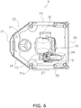
- FIG. 6 is a top view of the state when the console box 31 is disposed in the retracted position P2.
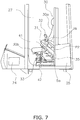
- FIG. 7 is a left side view of FIG. 6 .
- FIG. 8 shows the state when the left side face 55 of the cab 5 has been removed from FIG. 7 .
- the console box 31 is disposed in the retracted position P2 that is moved rearward (the direction of the arrow B in FIG. 4a ) around the rotation axis A from the operating position P1.
- the console box 31 In the operating position P1, the console box 31 is disposed substantially horizontally, with its front end 31a and rear end 31b at substantially the same height, as shown in FIG. 4a .
- the console box 31 In the retracted position P2, the console box 31 is disposed at an angle. More precisely, the rear end 31b of the console box 31 is located lower than the front end 31a.
- FIG. 9 shows the console box 31 in its operating position P1 and its retracted position P2.
- the console box 31 in the retracted position P2 is indicated by a two-dot chain line.
- the distance L2 in the horizontal direction from the front end 31 a to the rear end 31b of the console box 31 in the retracted position P2 is shorter than the distance L1 in the horizontal direction from the front end 31a to the rear end 31b of the console box 31 in the operating position P1.
- the spacing L2 between the front end 31a and the rear end 31b of the console box 31 in the retracted position P2 is shorter than the spacing L1 between the front end 31a and the rear end 31b of the console box 31 at the operating position P1.
- the first joint 41 side of the link 33 rotates around the second joint 42 along with rotation of the console box 31.
- the outer tube 43a moves upward with respect to the inner tube 43b, and the telescoping part 43 extends. That is, as shown in FIG. 9 , the length K2 of the link 33 in a state in which the console box 31 is in the retracted position P2 is greater than the length K1 of the link 33 in a state in which the console box 31 is in the operating position P1.
- the rotational axis A is provided within the rotation range D of the link 33 in side view.
- the console box 31 can be retracted from the front end left side of the seat bottom 30b of the operator's seat 30 by rotating the console box 31 rearward, as compared with FIGS. 2 and 3 . That is, since a space can be ensured on the left side of the front end of the seat bottom 30b of the operator's seat 30, the operator can easily get in or out of the vehicle through the door opening 27 formed on the left side of the operator's seat 30.
- the console box 31 and the support 35 are provided inside the cab 5 of the wheel loader 1 (an example of a work vehicle) of this embodiment.
- the console box 31 is disposed to the side of the operator's seat 30 and is configured to be rotatable in the forth and back direction.
- the support 35 has a rotational axis A disposed below the console box 31 along the left and right direction, and supports the console box 31 rotatably about the rotational axis A, between the operating position P1 in which the console box 31 is disposed horizontally and the retracted position P2 in which it is inclined at a position rotated rearward from the operating position P1. As shown in FIG.
- the spacing L2 in the horizontal direction between the front end 31a and rear end 31 b of the console box 31 is disposed in the retracted position P2 is shorter than the spacing L1 in the horizontal direction between the front end 31a and rear end 31b of the console box 31 is disposed in the operating position P1.
- the rotational axis A is disposed ahead of the center in the forth and back direction of the console box 31 disposed in the operating position P1, as shown in FIG. 4a .
- the joystick lever 32 (an example of an operation member) and the link 33 (an example of a transmission component) are further provided inside the cab 5 of the wheel loader 1 (an example of a work vehicle) in this embodiment.
- the joystick lever 32 is disposed on the upper side near the front end 31 a of the console box 31.
- the link 33 is disposed facing the floor 5a of the operator's seat 30 from the lower side near the front end 31a of the console box 31, and transmits the operation by the joystick lever 32 to the pilot valve 19 (an example of an operational object to be operated).
- the link 33 rotates with the second joint 42 (an example of the end on the floor side) as its fulcrum, while telescoping in or out as the console box 31 rotates from its operating position P1 to its retracted position P2.
- the rotational axis A is disposed within the rotation range D of the link 33 (an example transmission component) in side view.
- the telescoping width of the telescoping part 43 can be further reduced by disposing the rotational axis A within the rotation range D of the link 33 in side view.
- the link 33 (an example of a transmission component) is disposed ahead of the rotational axis A.
- the wheel loader 1 in this embodiment comprises the front frame 11, the rear frame 12, the steering cylinder 8 (an example of a hydraulic actuator), and the pilot valve 19 (an example of a control valve).
- the steering cylinder 8 is disposed from the front frame 11 to the rear frame 12, and changes the steering angle of the front frame 11 with respect to the rear frame 12.
- the pilot valve 19 controls the fluid supplied to the steering cylinders 8.
- console box 31 to which is provided the joystick lever 32 used for varying the steering angle, to be rotated so that its front end 31a moves far to the rear.
- the joystick lever 32 of the console box 31 was provided as an example of an operation member, but the joystick lever 32 is not the only option. Furthermore, the operation member itself need not be provided, and the configuration of this embodiment is applicable as long as the console box 31 is provided beside the operator's seat 30.
- the link 33 is provided and the operation of the joystick lever 32 is transmitted mechanically to the pilot valve 19, but the configuration may be such that no the link 33 is provided and the transmission is electrical. In this case, the transmission may be performed either wirelessly or by wire.
- the pilot valve 19 is provided as an example of an operational object to be operated, but the pilot valve 19 is not the only option.
- the configuration may be such that no pilot valve 19 is provided, the link 33 is connected to the steering valve 20 (an example of an operational object to be operated), and the steering valve 20 is operated directly by the joystick lever 32.
- the armrest 34 was provided on the upper side of the console box 31, but the armrest 34 may not be provided. Also, as shown in FIGS. 8 and 9 , the rear end of the armrest 34 protrudes rearward from the rear end 31b of the console box 31, but the armrest 34 may be formed so as not to protrude.
- a wheel loader was described as an example of a work vehicle, but the work vehicle may be a dump truck, a hydraulic excavator, or the like instead.
- the wheel loader 1 was described as an example of a work vehicle, and the steering wheel 37 was disposed in the cab 5, but depending on the work vehicle, there may be no steering wheel 37.
- the work vehicle pertaining to the present invention affords easy ingress and egress, and is widely applicable to various kinds of work vehicles such as a wheel loader.
Abstract
Description
- The present invention relates to a work vehicle.
- In a work vehicle such as a wheel loader or a hydraulic excavator, a configuration has been disclosed in which a console box is disposed to the side of the operator's seat, and an operating lever is provided to the console box (see
Patent Literature 1, for example). - With the hydraulic excavator disclosed in
Patent Literature 1, in a state in which a gate lock lever is disposed in a locked position, the console box is positioned on the front side, and in a state in which the gate lock lever is disposed in an open position, the console box is positioned on the rear side. - The operator gets in and out of the vehicle with the console box moved to the rear side.
- Patent Literature 1: 2012-127137
- However, since the distance the console box moves is short, there are times when the console box gets in the way, making difficult for the operator to get in and out of the vehicle.
- It is also possible to slide the console box far to the rear to facilitate operator ingress and egress, but if the inner wall of the cab is located just behind the operator's seat, the console box can be slid back only a small amount, so it is still difficult for the operator to get in and out.
- In light of the problems encountered with conventional work vehicles, it is an object of the present invention to provide a work vehicle that is easier to get in and out of.
- The work vehicle pertaining to the first invention comprises a console box and a support. The console box is disposed to the side of an operator's seat and is configured to be rotatable in the forth and back direction. The support has a rotational axis disposed in the left and right direction below the console box, and rotatably supports the console box around the rotational axis and between an operating position in which the console box is horizontally disposed and a retracted position in which the console box is inclined at a position where the console box has been rotated rearward from the operating position. The spacing in the horizontal direction between the front and rear ends of the console box disposed in the retracted position is less than the spacing in the horizontal direction between the front and rear ends of the console box disposed in the operating position.
- Thus rotating the console box rearward so that the spacing in the horizontal direction between the front and rear ends of the console box becomes shorter in the retracted position than in the operating position allows the front end of the console box to move far to the rear. Accordingly, it is easy for the operator to get in and out of the vehicle even though the door is to the side of the operator's seat.
- The work vehicle pertaining to the second invention is the work vehicle pertaining to the first invention, wherein the rotational axis is disposed ahead of the center in the forth and back direction of the console box disposed in the operating position.
- When the rotational axis is thus disposed ahead of the center in the forth and back direction of the console box disposed in the operating position, when the console box has rotated, its front end moves only a small amount upward. Therefore, the console box is less likely to get in the way of the operator's ingress and egress when in its retracted position, making it easier for the operator to get in and out of the vehicle. Also, when the console box has rotated, its rear end moves only a small amount rearward. Therefore, it is easy for the operator to get in and out of the vehicle even if the inner wall of the cap is just behind the operator's seat.
- The work vehicle pertaining to the third invention is the work vehicle pertaining to the first or second invention, further comprising an operation member and a transmission component. The operation member is disposed on the upper side near the front end of the console box. The transmission component is disposed facing the floor of the operator's seat from the lower side near the front end of the console box, and transmits the operation of the operation member to an operational object to be operated. The transmission component telescopes in and out along with rotation of the console box from the operating position to the retracted position, while rotating with its end on the floor side acting as the fulcrum.
- Consequently, the console box connected to the transmission component for transmitting the operation of the operation member can be rotated to the rear.
- Also, because the rotational axis is disposed ahead of the center in the forth and back direction of the console box disposed in the operating position, the transmission component and the rotational axis are both disposed toward the front of the console box, so there will be less change in the length of the transmission component accompanying rotation of the console box.
- That is, since the position of the rotational axis of the console box is not the same as the position of the end serving as the rotational fulcrum of the transmission component in side view, when the transmission component rotates along with the rotation of the console box, the length of the transmission component changes. However, since both the transmission component and the rotational axis are disposed near the front of the console box, the amount of rotation of the transmission component accompanying rotation of the console box is reduced, so the change in the length of the transmission component can also be suppressed.
- The work vehicle pertaining to the fourth invention is the work vehicle pertaining to the third invention, wherein the rotational axis is disposed within the rotation range of the transmission component in side view.
- Also, disposing the rotational axis within the rotation range of the transmission component in side view allows the telescoping width of the telescoping part to be reduced.
- The work vehicle pertaining to the fifth invention is the work vehicle pertaining to the third invention, wherein, in a state in which the console box is disposed in the operating position, the transmission component is disposed ahead of the rotational axis.
- Thus disposing both the transmission component and the rotation shaft near the front of the console box allows and the telescoping width of the telescoping part to be further reduced.
- The work vehicle pertaining to the sixth invention is the work vehicle pertaining to the third invention, comprising a front frame, a rear frame, a hydraulic actuator, and a control valve. The hydraulic actuator is disposed from the front frame to the rear frame and changes the steering angle of the front frame with respect to the rear frame. The control valve controls the fluid supplied to the hydraulic actuator. The operation member is a joystick lever. The operational object is the control valve.
- Thus, a console box provided with a joystick lever for controlling the steering angle can be rotated so that its front end moves far to the rear.
- The present invention provides a work vehicle that is easier to get in and out of.
-
-
FIG. 1 is a side view of a wheel loader in an embodiment pertaining to the present invention; -
FIG. 2 is a top view of the configuration inside the cab inFIG. 1 ; -
FIG. 3 is a left side view ofFIG. 2 ; -
FIG. 4a is a side view of the state when the side face of the cab has been removed fromFIG. 3 , andFIG. 4b is a cross section along the EE' line inFIG. 4a ; -
FIG. 5 is a front view of the internal configuration of the cab inFIG. 4a ; -
FIG. 6 is a top view of the state when the console box has been rotated rearward from the state inFIG. 2 ; -
FIG. 7 is a left side view ofFIG. 6 ; -
FIG. 8 is a side view of the state when the side face of the cab has been removed fromFIG. 7 ; and -
FIG. 9 is a side view of the state when the console box is disposed in the operating position and in the retracted position. - The wheel loader in an embodiment pertaining to the present invention will now be described through reference to the drawings.
-
FIG. 1 is a simplified diagram of the configuration of awheel loader 1 in this embodiment. Thewheel loader 1 in this embodiment mainly comprises abody frame 2, a work implement 3, a pair of front tires 4, acab 5, anengine compartment 6, a pair of rear tires 7, and a pair ofsteering cylinders 8. - In this embodiment, the front, back, left, and right directions mean those directions as viewed by an operator seated in an operator's seat 30 (discussed below) in the
cab 5. - The
wheel loader 1 performs earth loading work and the like with the work implement 3. - The
body frame 2 is what is known as an articulated type, and has a front frame 11, arear frame 12, and a linkingshaft 13. The front frame 11 is disposed in front of therear frame 12. The linkingshaft 13 is provided in the center of the vehicle width direction, and pivotably links the front frame 11 to therear frame 12. The front tires 4 are attached on the left and right sides of the front frame 11. The rear tires 7 are attached on the left and right sides of therear frame 12. - The work implement 3 is driven by hydraulic fluid from a work implement pump (not shown). The work implement 3 has a
boom 14, abucket 15, alift cylinder 16, and abucket cylinder 17. Theboom 14 is mounted on the front frame 11. Thebucket 15 is attached to the distal end of theboom 14. - The
lift cylinder 16 and thebucket cylinder 17 are hydraulic cylinders. One end of thelift cylinder 16 is attached to the front frame 11, and the other end of thelift cylinder 16 is attached to theboom 14. Thelift cylinder 16 telescopes in and out to pivot theboom 14 up and down. One end of thebucket cylinder 17 is attached to the front frame 11, and the other end of thebucket cylinder 17 is attached to thebucket 15 via abell crank 18. Thebucket cylinder 17 telescopes in and out to pivot thebucket 15 up and down. - The
steering cylinders 8 are disposed on the left and right sides in the vehicle width direction of the linkingshaft 13, and are each attached from the front frame 11 to therear frame 12. The flow of fluid supplied to the pair ofsteering cylinders 8 is changed to change the steering angle of the front frame 11 with respect to therear frame 12 and to change the travel direction of thewheel loader 1. - The
cab 5 is mounted on therear frame 12, inside of which are disposed asteering wheel 37 or joystick lever 32 (discussed below; seeFIG. 2 ) for steering, a lever for controlling the work implement 3, various display devices, and so forth. Theengine compartment 6 is disposed on therear frame 12 to the rear of thecab 5, and houses an engine. -
FIG. 2 is a top view of thecab 5.FIG. 3 is a partial side view of thecab 5. As shown inFIG. 2 , thecab 5 has a substantially hexagonal shape in top view, and has afront face 21, a rightinclined face 22, aright side face 23, a leftinclined face 24, aleft side face 25, and arear face 26. Thefront face 21 and therear face 26 are parallel to each other and are each disposed along the left and right direction (see arrow Y inFIG. 2 ). Theright side face 23 is disposed facing forward from the right end of therear face 26. The right inclinedface 22 is inclined with respect to the forth and back direction (see arrow X inFIG. 2 ), and is provided between the front end of theright side face 23 and the right end of thefront face 21. Theleft side face 25 is disposed facing forward from the left end of therear face 26. The left inclinedface 24 is inclined with respect to the forth and back direction and is provided between the front end of theleft side face 25 and the left end of thefront face 21. The right inclinedface 22 and the left inclinedface 24 are disposed so that their spacing decreases toward the front. The right inclinedface 22 and the left inclinedface 24 are inclined in the forth and back direction in order to avoid interference with the front frame during steering. - A
door opening 27 is formed at a position in front of theleft side face 25, and thedoor 28 shown inFIG. 1 is provided to thedoor opening 27. -
FIG. 4a shows the state when theleft side face 25 has been removed fromFIG. 3 . - The operator's
seat 30, aconsole box 31, ajoystick lever 32, alink 33, anarmrest 34, asupport 35, arotation lever 36, the steering wheel 37 (seeFIG. 2 ), and so forth are provided inside thecab 5. - As shown in
FIG. 2 , the operator'sseat 30 is disposed in the approximate center between theright side face 23 and theleft side face 25. The operator'sseat 30 is disposed at a position roughly facing thedoor opening 27. As shown inFIG. 4a , the operator'sseat 30 has abackrest 30a, aseat bottom 30b, alower frame 30c (discussed below; seeFIG. 5 ) on the lower side of theseat bottom 30b, and so forth, and springs (not shown) are disposed on the lower side of thelower frame 30c. - The
steering wheel 37 is operated by the operator when changing the steering angle of the front frame 11 with respect to therear frame 12 during movement, for example. As shown inFIG. 2 , thesteering wheel 37 is disposed in front of the operator'sseat 30 and between the rightinclined face 22 and the left inclinedface 24. - The
console box 31 is disposed on the left lateral side of the operator'sseat 30. Theconsole box 31 can also be said to be disposed between the operator'sseat 30 and thedoor opening 27. As shown inFIG. 4a , theconsole box 31 is formed longer in the forth and back direction, and is disposed substantially horizontally. A linking member (not shown) for linking thejoystick lever 32 and the link 33 (discussed below) and the like are provided inside theconsole box 31. The position of theconsole box 31 disposed so as to be substantially horizontal as shown inFIG. 4a is an operating position P1. The operating position P1 is the position of theconsole box 31 when the operator is seated in the operator'sseat 30 and operating thejoystick lever 32. - As shown in
FIG. 4a , thejoystick lever 32 is provided on the upper side near thefront end 31a of theconsole box 31 so as to protrude upward. - The
joystick lever 32 is used during work such as loading and conveying earth. The steering angle of the front frame 11 with respect to therear frame 12 is changed by rotating thejoystick lever 32 in the left and right direction. - The
link 33 is a universal joint, and as shown inFIG. 4a includes a first joint 41, a second joint 42, and atelescoping part 43. The first joint 41 and the second joint 42 are disposed at both ends of thetelescoping part 43. Thetelescoping part 43 is made up of anouter tube 43a and aninner tube 43b, and theouter tube 43a and theinner tube 43b are spline-coupled. -
FIG. 4b is a cross section along the EE' line inFIG. 4a . As shown inFIG. 4b , tooth-like grooves are formed on the inner periphery of theouter tube 43a, and tooth-like grooves that mate with the tooth-like grooves in theouter tube 43a are formed on the outer periphery of theinner tube 43b. Also, the grooves are formed along the lengthwise direction. With this configuration, theouter tube 43a and theinner tube 43b are fixed to each other around the center axis F, and can transmit the operation of thejoystick lever 32. Theouter tube 43a and theinner cylinder 43b can move in the direction along the center axis F, allowing them to telescope. - The first joint 41 is attached to the lower side of the
console box 31 and is linked to thejoystick lever 32 by a linking member (not shown). The second joint 42 is inserted into and attached to thefloor 5 a of thecab 5. - The
link 33 is covered with a cover C (see the dotted line). - Also, the second joint 42 of the
link 33 is connected to apilot valve 19 as shown inFIG. 3 . The operation of thejoystick lever 32 is transmitted to thepilot valve 19 via thelink 33, and the pilot pressure inputted to asteering valve 20 is adjusted. The steeringvalve 20 adjusts the flow of the fluid supplied to thesteering cylinder 8 according to the inputted pilot pressure. This allows steering to be performed by operating thejoystick lever 32. - As shown in
FIG. 4a , thearmrest 34 is disposed on the upper side of theconsole box 31 via abracket 38. The operator seated in the operator'sseat 30 can rest his elbows on the armrest 34 in a state in which theconsole box 31 is disposed in the operating position P1. -
FIG. 5 is a view of the vicinity of the operator'sseat 30 as seen from the front side. InFIG. 5 , thelink 33 and the cover C are in front of thesupport 35, but thesupport 35 is indicated by a solid line and thelink 33 and the cover C are indicated by a dotted line for the sake of illustration. - The
support 35 mainly has a fixingframe 50, afirst rotation member 51, asecond rotation member 52, afirst shaft 53, and asecond shaft 54. - As shown in
FIG. 4a , the fixingframe 50 is disposed below theconsole box 31 and to the rear of thelink 33. As shown inFIG. 5 , the fixingframe 50 protrudes from thelower frame 30c of the operator'sseat 30 toward the left side face. The fixingframe 50 has a first fixingportion 61, asecond fixing portion 62, afirst shaft support 63, and asecond shaft support 64. - The
first fixing portion 61 is connected to thelower frame 30c and is a portion that protrudes substantially horizontally from thelower frame 30c toward the left side face. Thesecond fixing portion 62 is substantially U-shaped and is connected to the end on the left side face side of the first fixingportion 61. Thefirst shaft support 63 is fixed to the upper side of the first fixingportion 61. Thefirst shaft support 63 has two plate-like portions 63a disposed opposite each other with a predetermined spacing in the left and right direction. Holes are formed in the two plate-like portions 63a along the left and right direction. Inserting thefirst shaft 53 fixed to the first rotation member 51 (discussed below) into these holes allows thefirst shaft support 63 to rotatably support thefirst rotation member 51. Thesecond shaft support 64 is provided on theupper end portion 62a on the left side face side of the second fixingportion 62. Thesecond shaft support 64 has two plate-like portions 64a disposed opposite each other with a predetermined spacing in the left and right direction. Holes are formed in the two plate-like portions 64a along the left and right direction. Inserting thesecond shaft 54 fixed to the second rotation member 52 (discussed below) into these holes allows thesecond shaft support 64 to rotatably support thesecond rotation member 52. - The
first rotation member 51 and thesecond rotation member 52 are each formed by bending a plate-like member, and are disposed opposite each other and aligned in the left and right direction, between theconsole box 31 and the fixingframe 50. Thefirst rotation member 51 and thesecond rotation member 52 are formed by being bent so that the spacing between them is wider at the lower end than at the upper end. - The upper ends of the
first rotation member 51 and thesecond rotation member 52 are fixed to theframe 31f of theconsole box 31. The lower end of thefirst rotation member 51 is inserted between the two plate-like portions 63a of thefirst shaft support 63. The lower end of thesecond rotation member 52 is inserted into the two plate-like portions 64 a of thesecond shaft support 64. - The
first shaft 53 is fixed to the lower end of thefirst rotation member 51. Thefirst rotation member 51 protrudes downward in the right and left direction. Thefirst shaft 53 is inserted into the holes in the plate-like portions 63a of thefirst shaft support 63. Thesecond shaft 54 is fixed to the lower end of thesecond rotation member 52. Thesecond rotation member 52 protrudes downward in the right and left direction. Thesecond shaft 54 is inserted into the holes of the plate-like portions 64a of thesecond shaft support 64. Thefirst shaft 53 and thesecond shaft 54 are disposed coaxially along the left and right direction. - The
first rotation member 51 and thesecond rotation member 52 can rotate relative to the fixedframe 50 around thefirst shaft 53 and thesecond shaft 54. Also, thefirst rotation member 51 and thesecond rotation member 52 are fixed to thelower frame 30c of theconsole box 31. Therefore, theconsole box 31 is also rotated by the rotation of thefirst rotation member 51 and thesecond rotation member 52. - The rotational axis A of the
console box 31 is the center of thefirst shaft 53 and thesecond shaft 54, and is shown inFIG. 4a andFIG. 5 . As shown inFIG. 4a , the rotational axis A is disposed on the lower side of theconsole box 31, ahead of the center (see the line M) between thefront end 31a and therear end 31b of theconsole box 31. - The
rotation lever 36 is grasped by the operator when theconsole box 31 is to be rotated. - The
rotation lever 36 is connected to the lower side of theconsole box 31. When the operator grips therotation lever 36 and rotates it rearward, theconsole box 31 rotates rearward as shown inFIGS. 6 to 8 (discussed below). - Next, the rotation operation of the
console box 31 of thewheel loader 1 in an embodiment pertaining to the present invention will be described. - The
console box 31 shown inFIG. 4a andFIG. 5 is disposed substantially horizontally, and is disposed at the operating position P1 where the operator operates thejoystick lever 32. When the operator grips therotation lever 36 from this state and rotates it rearward as indicated by the arrow B inFIG. 4a , theconsole box 31 is disposed in a retracted position P2. Theconsole box 31 may be locked in either the operating position P1 or the retracted position P2. -
FIG. 6 is a top view of the state when theconsole box 31 is disposed in the retracted position P2.FIG. 7 is a left side view ofFIG. 6 .FIG. 8 shows the state when the left side face 55 of thecab 5 has been removed fromFIG. 7 . - As shown in
FIGS. 6 to 8 , theconsole box 31 is disposed in the retracted position P2 that is moved rearward (the direction of the arrow B inFIG. 4a ) around the rotation axis A from the operating position P1. - In the operating position P1, the
console box 31 is disposed substantially horizontally, with itsfront end 31a andrear end 31b at substantially the same height, as shown inFIG. 4a . On the other hand, as shown inFIG. 8 , in the retracted position P2, theconsole box 31 is disposed at an angle. More precisely, therear end 31b of theconsole box 31 is located lower than thefront end 31a. -
FIG. 9 shows theconsole box 31 in its operating position P1 and its retracted position P2. InFIG. 9 , theconsole box 31 in the retracted position P2 is indicated by a two-dot chain line. As shown inFIG. 9 , the distance L2 in the horizontal direction from thefront end 31 a to therear end 31b of theconsole box 31 in the retracted position P2 is shorter than the distance L1 in the horizontal direction from thefront end 31a to therear end 31b of theconsole box 31 in the operating position P1. To put this another way, in top view, the spacing L2 between thefront end 31a and therear end 31b of theconsole box 31 in the retracted position P2 is shorter than the spacing L1 between thefront end 31a and therear end 31b of theconsole box 31 at the operating position P1. - Also, the first joint 41 side of the
link 33 rotates around the second joint 42 along with rotation of theconsole box 31. Here, since the first joint 41 rotates around the rotational axis A, theouter tube 43a moves upward with respect to theinner tube 43b, and thetelescoping part 43 extends. That is, as shown inFIG. 9 , the length K2 of thelink 33 in a state in which theconsole box 31 is in the retracted position P2 is greater than the length K1 of thelink 33 in a state in which theconsole box 31 is in the operating position P1. - Further, as shown in
FIG. 9 , the rotational axis A is provided within the rotation range D of thelink 33 in side view. - After thus rotating the
console box 31 rearward, the operator gets in or out of thewheel loader 1 through thedoor opening 27. - As shown in
FIGS. 6 and7 , theconsole box 31 can be retracted from the front end left side of theseat bottom 30b of the operator'sseat 30 by rotating theconsole box 31 rearward, as compared withFIGS. 2 and3 . That is, since a space can be ensured on the left side of the front end of theseat bottom 30b of the operator'sseat 30, the operator can easily get in or out of the vehicle through the door opening 27 formed on the left side of the operator'sseat 30. - The
console box 31 and thesupport 35 are provided inside thecab 5 of the wheel loader 1 (an example of a work vehicle) of this embodiment. Theconsole box 31 is disposed to the side of the operator'sseat 30 and is configured to be rotatable in the forth and back direction. Thesupport 35 has a rotational axis A disposed below theconsole box 31 along the left and right direction, and supports theconsole box 31 rotatably about the rotational axis A, between the operating position P1 in which theconsole box 31 is disposed horizontally and the retracted position P2 in which it is inclined at a position rotated rearward from the operating position P1. As shown inFIG. 9 , the spacing L2 in the horizontal direction between thefront end 31a andrear end 31 b of theconsole box 31 is disposed in the retracted position P2 is shorter than the spacing L1 in the horizontal direction between thefront end 31a andrear end 31b of theconsole box 31 is disposed in the operating position P1. - Thus rotating the
console box 31 rearward so that the spacing L2 is shorter than the spacing L1 allows thefront end 31a of theconsole box 31 to move far to the rear. Therefore, as shown inFIGS. 6 and7 , even if thedoor opening 27 is located to the side of the operator'sseat 30, the operator can easily get in and out. - With the wheel loader 1 (an example of a work vehicle) in this embodiment, the rotational axis A is disposed ahead of the center in the forth and back direction of the
console box 31 disposed in the operating position P1, as shown inFIG. 4a . - Because the rotational axis A is thus disposed ahead of the center (see the line M shown in
FIG. 4a ) in the forth and back direction of theconsole box 31 disposed in the operating position P1, when the console box when 31 is rotated, itsfront end 31a moves upward only a small amount. Therefore, theconsole box 31 is less likely to hinder the ingress or egress of the operator in the retracted position P2, making it easier for the operator to get in and out. Also, when theconsole box 31 is rotated, itsrear end 31b moves rearward only a small amount. Therefore, even if therear face 26 of thecab 5 is just behind the operator'sseat 30, the operator can still get in and out with ease. - As shown in
FIG. 4a , the joystick lever 32 (an example of an operation member) and the link 33 (an example of a transmission component) are further provided inside thecab 5 of the wheel loader 1 (an example of a work vehicle) in this embodiment. Thejoystick lever 32 is disposed on the upper side near thefront end 31 a of theconsole box 31. Thelink 33 is disposed facing thefloor 5a of the operator'sseat 30 from the lower side near thefront end 31a of theconsole box 31, and transmits the operation by thejoystick lever 32 to the pilot valve 19 (an example of an operational object to be operated). Thelink 33 rotates with the second joint 42 (an example of the end on the floor side) as its fulcrum, while telescoping in or out as theconsole box 31 rotates from its operating position P1 to its retracted position P2. - This allows the
console box 31, to which is connected thelink 33 for transmitting the operation of thejoystick lever 32, to rotate to the rear. - Also, since the
link 33 and the rotational axis A are both disposed toward the front of theconsole box 31, so there will be less change in the length of thelink 33 accompanying rotation of theconsole box 31. - Specifically, in side view, since the position of the rotational axis A of the
console box 31 is not the same as the position of the second joint 42, which is the pivot point of thelink 33, when thelink 31 rotates along with the rotation of theconsole box 31, the length of thelink 31 changes. However, since thelink 33 and the rotational axis A are both disposed toward the front of theconsole box 31, the amount of rotation of thelink 33 accompanying rotation of theconsole box 31 is reduced, so the change in the length of thelink 33 can also be suppressed. - With the
wheel loader 1 in this embodiment, as shown inFIG. 9 , the rotational axis A is disposed within the rotation range D of the link 33 (an example transmission component) in side view. - Also, the telescoping width of the
telescoping part 43 can be further reduced by disposing the rotational axis A within the rotation range D of thelink 33 in side view. - With the
wheel loader 1 in this embodiment, in a state in which theconsole box 31 is disposed in the operating position P1, the link 33 (an example of a transmission component) is disposed ahead of the rotational axis A. - Thus disposing both the
link 33 and the rotational axis A toward the front of theconsole box 31 allows the telescoping width of thetelescoping part 43 to be further reduced. - The
wheel loader 1 in this embodiment comprises the front frame 11, therear frame 12, the steering cylinder 8 (an example of a hydraulic actuator), and the pilot valve 19 (an example of a control valve). Thesteering cylinder 8 is disposed from the front frame 11 to therear frame 12, and changes the steering angle of the front frame 11 with respect to therear frame 12. Thepilot valve 19 controls the fluid supplied to thesteering cylinders 8. - This allows the
console box 31, to which is provided thejoystick lever 32 used for varying the steering angle, to be rotated so that itsfront end 31a moves far to the rear. - An embodiment of the present invention was described above, but the present invention is not limited to or by the above embodiment, and various modifications are possible without departing from the gist of the invention.
- With the
wheel loader 1 in the above embodiment, thejoystick lever 32 of theconsole box 31 was provided as an example of an operation member, but thejoystick lever 32 is not the only option. Furthermore, the operation member itself need not be provided, and the configuration of this embodiment is applicable as long as theconsole box 31 is provided beside the operator'sseat 30. - With the
wheel loader 1 in the above embodiment, thelink 33 is provided and the operation of thejoystick lever 32 is transmitted mechanically to thepilot valve 19, but the configuration may be such that no thelink 33 is provided and the transmission is electrical. In this case, the transmission may be performed either wirelessly or by wire. - With the
wheel loader 1 in the above embodiment, thepilot valve 19 is provided as an example of an operational object to be operated, but thepilot valve 19 is not the only option. For instance, the configuration may be such that nopilot valve 19 is provided, thelink 33 is connected to the steering valve 20 (an example of an operational object to be operated), and the steeringvalve 20 is operated directly by thejoystick lever 32. - In the above embodiment, the
armrest 34 was provided on the upper side of theconsole box 31, but the armrest 34 may not be provided. Also, as shown inFIGS. 8 and9 , the rear end of the armrest 34 protrudes rearward from therear end 31b of theconsole box 31, but the armrest 34 may be formed so as not to protrude. - In the above embodiment, a wheel loader was described as an example of a work vehicle, but the work vehicle may be a dump truck, a hydraulic excavator, or the like instead.
- In the above embodiment the
wheel loader 1 was described as an example of a work vehicle, and thesteering wheel 37 was disposed in thecab 5, but depending on the work vehicle, there may be nosteering wheel 37. - The work vehicle pertaining to the present invention affords easy ingress and egress, and is widely applicable to various kinds of work vehicles such as a wheel loader.
-
- 1 wheel loader
- 2 body frame
- 3 work implement
- 4 front tire
- 5 cab
- 5a floor
- 6 engine compartment
- 7 rear tire
- 8 steering cylinder
- 11 front frame
- 12 rear frame
- 13 linking shaft
- 14 boom
- 15 bucket
- 16 lift cylinder
- 17 bucket cylinder
- 18 bell crank
- 19 pilot valve
- 20 steering valve
- 21 front face
- 22 right inclined face
- 23 right side face
- 24 left inclined face
- 25 left side face
- 26 rear face
- 27 door opening
- 28 door
- 30 operator's seat
- 30a backrest
- 30b seat bottom
- 30c lower frame
- 31 console box
- 31a front end
- 31b rear end
- 31f frame
- 32 joystick lever
- 33 link
- 34 armrest
- 35 support
- 36 rotation lever
- 37 steering wheel
- 38 bracket
- 41 first joint
- 42 second joint
- 43 telescoping part
- 43a outer tube
- 43b inner tube
- 50 fixing frame
- 51 first rotation member
- 52 second rotation member
- 53 first shaft
- 54 second shaft
- 61 first fixing portion
- 62 second fixing portion
- 62a upper end
- 63 first shaft support
- 63a plate-like portion
- 64 second shaft support
- 64a plate-like portion
- C cover
- D rotation range
- L1 spacing
- L2 spacing
- P1 operating position
- P2 retracted position
Claims (6)
- A work vehicle, comprising:a console box disposed to a side of an operator's seat, the console box configured to be rotatable in a forth and back direction; anda support including a rotational axis disposed in a left and right direction below the console box, the support rotatably supporting the console box around the rotational axis and between an operating position in which the console box is horizontally disposed and a retracted position in which the console box is inclined at a position where the console box has been rotated rearward from the operating position,a spacing in a horizontal direction between front and rear ends of the console box disposed in the retracted position being less than a spacing in the horizontal direction between front and rear ends of the console box disposed in the operating position.
- The work vehicle according to Claim 1,
wherein the rotational axis is disposed ahead of a center in the forth and back direction of the console box disposed in the operating position. - The work vehicle according to Claim 1 or 2, further comprising:an operation member disposed on the upper side near the front end of the console box; anda transmission component disposed facing a floor of the operator's seat from a lower side near the front end of the console box, the transmission component configured to transmit an operation of the operation member to an operational object to be operated,wherein the transmission component telescopes in and out along with rotation of the console box from the operating position to the retracted position, while rotating with an end of the transmission component on the floor side acting as the fulcrum.
- The work vehicle according to Claim 3,
wherein the rotational axis is disposed within a rotation range of the transmission component in side view. - The work vehicle according to Claim 3,
wherein, in a state in which the console box is disposed in the operating position, the transmission component is disposed ahead of the rotational axis. - The work vehicle according to Claim 3, comprising:a front frame;a rear frame;a hydraulic actuator disposed from the front frame to the rear frame, the hydraulic actuator configured to change a steering angle of the front frame with respect to the rear frame; anda control valve configured to control fluid supplied to the hydraulic actuator,wherein the operation member is a joystick lever, andthe operational object is the control valve.
Applications Claiming Priority (1)
| Application Number | Priority Date | Filing Date | Title |
|---|---|---|---|
| PCT/JP2015/080678 WO2017072937A1 (en) | 2015-10-30 | 2015-10-30 | Work vehicle |
Publications (3)
| Publication Number | Publication Date |
|---|---|
| EP3258017A1 true EP3258017A1 (en) | 2017-12-20 |
| EP3258017A4 EP3258017A4 (en) | 2019-03-27 |
| EP3258017B1 EP3258017B1 (en) | 2020-09-02 |
Family
ID=58629977
Family Applications (1)
| Application Number | Title | Priority Date | Filing Date |
|---|---|---|---|
| EP15907301.4A Active EP3258017B1 (en) | 2015-10-30 | 2015-10-30 | Work vehicle with rotatable console box |
Country Status (5)
| Country | Link |
|---|---|
| US (1) | US10370821B2 (en) |
| EP (1) | EP3258017B1 (en) |
| JP (1) | JP6702999B2 (en) |
| CN (1) | CN107407070B (en) |
| WO (1) | WO2017072937A1 (en) |
Families Citing this family (11)
| Publication number | Priority date | Publication date | Assignee | Title |
|---|---|---|---|---|
| JP6487316B2 (en) * | 2015-12-25 | 2019-03-20 | 株式会社Kcm | Construction machine operation device |
| US10196795B2 (en) * | 2016-10-21 | 2019-02-05 | Komatsu Ltd. | Work vehicle |
| EP3190236B1 (en) * | 2016-10-21 | 2019-09-18 | Komatsu, Ltd. | Work vehicle with control console |
| JP6824118B2 (en) * | 2017-06-26 | 2021-02-03 | 株式会社小松製作所 | Work vehicle cab and work vehicle |
| WO2019131721A1 (en) * | 2017-12-27 | 2019-07-04 | 株式会社クボタ | Work equipment and method for producing work equipment |
| JP7281869B2 (en) * | 2018-03-14 | 2023-05-26 | 株式会社小松製作所 | work vehicle |
| JP7195872B2 (en) * | 2018-10-26 | 2022-12-26 | 株式会社小松製作所 | work vehicle |
| GB2579075B (en) * | 2018-11-19 | 2021-06-16 | Caterpillar Inc | Work machine with sensor enabled user control |
| US11292504B2 (en) * | 2019-03-20 | 2022-04-05 | Volvo Car Corporation | Vehicle having multiple driving positions |
| US11001146B2 (en) * | 2019-04-05 | 2021-05-11 | Caterpillar Paving Products Inc. | Machine console system |
| KR102294109B1 (en) * | 2020-12-21 | 2021-08-25 | 안국수 | Multi-joint driven console box for construction equipment |
Family Cites Families (25)
| Publication number | Priority date | Publication date | Assignee | Title |
|---|---|---|---|---|
| NL8200614A (en) * | 1982-02-17 | 1983-09-16 | Rotterdamsche Droogdok Mij | COMMERCIAL VEHICLE. |
| US5052512A (en) * | 1990-08-14 | 1991-10-01 | Ford New Holland, Inc. | Reversible control level linkage |
| JPH0624048U (en) * | 1992-08-29 | 1994-03-29 | 油谷重工株式会社 | Control equipment for construction machinery |
| JP2577363Y2 (en) * | 1993-05-13 | 1998-07-23 | 油谷重工株式会社 | Control equipment for construction machinery |
| JP2741179B2 (en) | 1995-03-30 | 1998-04-15 | 新キャタピラー三菱株式会社 | Console box device for construction machinery |
| JP3146153B2 (en) * | 1996-04-09 | 2001-03-12 | 株式会社クボタ | Backhoe |
| JP3184155B2 (en) * | 1998-08-06 | 2001-07-09 | 住友建機株式会社 | Gate lock device for construction machinery |
| JP3392363B2 (en) * | 1998-12-18 | 2003-03-31 | 日立建機株式会社 | Locking mechanism for console box for construction machinery |
| JP2002019530A (en) * | 2000-07-04 | 2002-01-23 | Kasai Kogyo Co Ltd | Console box for vehicle |
| JP2002070079A (en) * | 2000-08-29 | 2002-03-08 | Hitachi Constr Mach Co Ltd | Console box for construction equipment |
| US6971279B2 (en) * | 2003-02-12 | 2005-12-06 | Volvo Construction Equipment Holding Sweden Ab | Control lever safety apparatus for heavy equipment |
| JP4057542B2 (en) | 2004-02-04 | 2008-03-05 | 日立建機株式会社 | Construction machinery |
| JP2006077544A (en) * | 2004-09-13 | 2006-03-23 | Hitachi Constr Mach Co Ltd | Cabin device of construction machine |
| KR100652873B1 (en) | 2005-02-18 | 2006-12-01 | 볼보 컨스트럭션 이키프먼트 홀딩 스웨덴 에이비 | safety lever device of heavy epuipment |
| JP4997562B2 (en) * | 2005-10-03 | 2012-08-08 | 株式会社小松製作所 | Console device |
| CN1986978A (en) * | 2006-12-27 | 2007-06-27 | 广西柳工机械股份有限公司 | Servo controller for loading machine |
| JP5332557B2 (en) * | 2008-12-01 | 2013-11-06 | コベルコ建機株式会社 | Doorway opening / closing device for construction machinery |
| CN101936019B (en) * | 2010-08-27 | 2012-06-06 | 江苏柳工机械有限公司 | Operating device of skid-steering loader |
| JP5420526B2 (en) | 2010-12-16 | 2014-02-19 | 日立建機株式会社 | Construction machinery |
| CN103052753B (en) * | 2011-08-08 | 2014-05-21 | 株式会社小松制作所 | Wheel loader |
| EP2574699B1 (en) * | 2011-09-30 | 2014-04-30 | Caterpillar, Inc. | Security blocking of cabin exit |
| JP5803984B2 (en) | 2013-06-13 | 2015-11-04 | コベルコ建機株式会社 | Work machine |
| JP5983639B2 (en) * | 2014-01-20 | 2016-09-06 | トヨタ自動車株式会社 | Occupant protection device in the event of a vehicle side collision |
| CN107075835B (en) * | 2016-10-21 | 2020-01-21 | 株式会社小松制作所 | Working vehicle |
| EP3190236B1 (en) * | 2016-10-21 | 2019-09-18 | Komatsu, Ltd. | Work vehicle with control console |
-
2015
- 2015-10-30 US US15/555,724 patent/US10370821B2/en active Active
- 2015-10-30 CN CN201580077475.3A patent/CN107407070B/en active Active
- 2015-10-30 WO PCT/JP2015/080678 patent/WO2017072937A1/en active Application Filing
- 2015-10-30 JP JP2017547299A patent/JP6702999B2/en active Active
- 2015-10-30 EP EP15907301.4A patent/EP3258017B1/en active Active
Also Published As
| Publication number | Publication date |
|---|---|
| CN107407070B (en) | 2020-10-27 |
| EP3258017A4 (en) | 2019-03-27 |
| US10370821B2 (en) | 2019-08-06 |
| US20180058037A1 (en) | 2018-03-01 |
| JPWO2017072937A1 (en) | 2018-08-16 |
| JP6702999B2 (en) | 2020-06-03 |
| WO2017072937A1 (en) | 2017-05-04 |
| CN107407070A (en) | 2017-11-28 |
| EP3258017B1 (en) | 2020-09-02 |
Similar Documents
| Publication | Publication Date | Title |
|---|---|---|
| EP3258017A1 (en) | Work vehicle | |
| EP3190236B1 (en) | Work vehicle with control console | |
| EP3226553B1 (en) | Work vehicle periphery monitoring system, work vehicle, and work vehicle periphery monitoring method | |
| EP3385458B1 (en) | Work vehicle and display device | |
| EP2628375A1 (en) | Driving cab in tractor | |
| EP2700754A1 (en) | Working vehicle | |
| WO2016140042A1 (en) | Work vehicle and ripper device | |
| JP2017082412A (en) | Crawler-type tractor | |
| EP2799626B1 (en) | Parallel linkage-type working apparatus for construction equipment | |
| JP6293289B2 (en) | Tractor | |
| US20140304945A1 (en) | Attaching structure for door of working vehicle | |
| JP2018042007A (en) | Work vehicle | |
| US20130186703A1 (en) | Tractor | |
| US10196098B2 (en) | Vehicle and a system for operating a work implement of a vehicle | |
| JP6670268B2 (en) | Tractor | |
| US20230347995A1 (en) | Work vehicle | |
| JP7362101B2 (en) | Condition detection system for agricultural machinery | |
| EP1264938A1 (en) | Earthmoving machine and actuating device for controlling lateral movement of a loading shovel | |
| JP2016160649A (en) | Work vehicle and ripper device | |
| CN102355810B (en) | Riding type agricultural working machine and riding type rice transplanter as example thereof | |
| JP5941076B2 (en) | Construction machinery | |
| JP5808040B2 (en) | Tractor | |
| US20150114737A1 (en) | Hood assembly for a machine | |
| JP2012178000A (en) | Work vehicle |
Legal Events
| Date | Code | Title | Description |
|---|---|---|---|
| STAA | Information on the status of an ep patent application or granted ep patent |
Free format text: STATUS: THE INTERNATIONAL PUBLICATION HAS BEEN MADE |
|
| PUAI | Public reference made under article 153(3) epc to a published international application that has entered the european phase |
Free format text: ORIGINAL CODE: 0009012 |
|
| STAA | Information on the status of an ep patent application or granted ep patent |
Free format text: STATUS: REQUEST FOR EXAMINATION WAS MADE |
|
| 17P | Request for examination filed |
Effective date: 20170907 |
|
| AK | Designated contracting states |
Kind code of ref document: A1 Designated state(s): AL AT BE BG CH CY CZ DE DK EE ES FI FR GB GR HR HU IE IS IT LI LT LU LV MC MK MT NL NO PL PT RO RS SE SI SK SM TR |
|
| AX | Request for extension of the european patent |
Extension state: BA ME |
|
| RIC1 | Information provided on ipc code assigned before grant |
Ipc: B62D 1/02 20060101ALI20181009BHEP Ipc: B60R 7/04 20060101ALI20181009BHEP Ipc: B66C 13/54 20060101ALI20181009BHEP Ipc: E02F 9/16 20060101AFI20181009BHEP Ipc: F16G 13/16 20060101ALI20181009BHEP Ipc: E02F 9/20 20060101ALI20181009BHEP |
|
| DAV | Request for validation of the european patent (deleted) | ||
| DAX | Request for extension of the european patent (deleted) | ||
| A4 | Supplementary search report drawn up and despatched |
Effective date: 20190221 |
|
| RIC1 | Information provided on ipc code assigned before grant |
Ipc: B62D 12/00 20060101ALI20190215BHEP Ipc: B60R 7/04 20060101ALI20190215BHEP Ipc: B62D 1/02 20060101ALI20190215BHEP Ipc: B60N 2/75 20180101ALI20190215BHEP Ipc: B66C 13/54 20060101ALI20190215BHEP Ipc: E02F 9/20 20060101ALI20190215BHEP Ipc: B62D 1/18 20060101ALI20190215BHEP Ipc: E02F 9/16 20060101AFI20190215BHEP Ipc: B60N 2/24 20060101ALI20190215BHEP Ipc: B62D 1/22 20060101ALI20190215BHEP Ipc: F16G 13/16 20060101ALI20190215BHEP |
|
| GRAP | Despatch of communication of intention to grant a patent |
Free format text: ORIGINAL CODE: EPIDOSNIGR1 |
|
| STAA | Information on the status of an ep patent application or granted ep patent |
Free format text: STATUS: GRANT OF PATENT IS INTENDED |
|
| INTG | Intention to grant announced |
Effective date: 20200527 |
|
| GRAS | Grant fee paid |
Free format text: ORIGINAL CODE: EPIDOSNIGR3 |
|
| GRAA | (expected) grant |
Free format text: ORIGINAL CODE: 0009210 |
|
| STAA | Information on the status of an ep patent application or granted ep patent |
Free format text: STATUS: THE PATENT HAS BEEN GRANTED |
|
| AK | Designated contracting states |
Kind code of ref document: B1 Designated state(s): AL AT BE BG CH CY CZ DE DK EE ES FI FR GB GR HR HU IE IS IT LI LT LU LV MC MK MT NL NO PL PT RO RS SE SI SK SM TR |
|
| REG | Reference to a national code |
Ref country code: GB Ref legal event code: FG4D |
|
| REG | Reference to a national code |
Ref country code: AT Ref legal event code: REF Ref document number: 1308940 Country of ref document: AT Kind code of ref document: T Effective date: 20200915 Ref country code: CH Ref legal event code: EP |
|
| REG | Reference to a national code |
Ref country code: DE Ref legal event code: R096 Ref document number: 602015058651 Country of ref document: DE |
|
| REG | Reference to a national code |
Ref country code: IE Ref legal event code: FG4D |
|
| REG | Reference to a national code |
Ref country code: SE Ref legal event code: TRGR |
|
| REG | Reference to a national code |
Ref country code: LT Ref legal event code: MG4D |
|
| PG25 | Lapsed in a contracting state [announced via postgrant information from national office to epo] |
Ref country code: HR Free format text: LAPSE BECAUSE OF FAILURE TO SUBMIT A TRANSLATION OF THE DESCRIPTION OR TO PAY THE FEE WITHIN THE PRESCRIBED TIME-LIMIT Effective date: 20200902 Ref country code: BG Free format text: LAPSE BECAUSE OF FAILURE TO SUBMIT A TRANSLATION OF THE DESCRIPTION OR TO PAY THE FEE WITHIN THE PRESCRIBED TIME-LIMIT Effective date: 20201202 Ref country code: LT Free format text: LAPSE BECAUSE OF FAILURE TO SUBMIT A TRANSLATION OF THE DESCRIPTION OR TO PAY THE FEE WITHIN THE PRESCRIBED TIME-LIMIT Effective date: 20200902 Ref country code: NO Free format text: LAPSE BECAUSE OF FAILURE TO SUBMIT A TRANSLATION OF THE DESCRIPTION OR TO PAY THE FEE WITHIN THE PRESCRIBED TIME-LIMIT Effective date: 20201202 Ref country code: FI Free format text: LAPSE BECAUSE OF FAILURE TO SUBMIT A TRANSLATION OF THE DESCRIPTION OR TO PAY THE FEE WITHIN THE PRESCRIBED TIME-LIMIT Effective date: 20200902 Ref country code: GR Free format text: LAPSE BECAUSE OF FAILURE TO SUBMIT A TRANSLATION OF THE DESCRIPTION OR TO PAY THE FEE WITHIN THE PRESCRIBED TIME-LIMIT Effective date: 20201203 |
|
| REG | Reference to a national code |
Ref country code: NL Ref legal event code: MP Effective date: 20200902 |
|
| REG | Reference to a national code |
Ref country code: AT Ref legal event code: MK05 Ref document number: 1308940 Country of ref document: AT Kind code of ref document: T Effective date: 20200902 |
|
| PG25 | Lapsed in a contracting state [announced via postgrant information from national office to epo] |
Ref country code: RS Free format text: LAPSE BECAUSE OF FAILURE TO SUBMIT A TRANSLATION OF THE DESCRIPTION OR TO PAY THE FEE WITHIN THE PRESCRIBED TIME-LIMIT Effective date: 20200902 Ref country code: LV Free format text: LAPSE BECAUSE OF FAILURE TO SUBMIT A TRANSLATION OF THE DESCRIPTION OR TO PAY THE FEE WITHIN THE PRESCRIBED TIME-LIMIT Effective date: 20200902 Ref country code: PL Free format text: LAPSE BECAUSE OF FAILURE TO SUBMIT A TRANSLATION OF THE DESCRIPTION OR TO PAY THE FEE WITHIN THE PRESCRIBED TIME-LIMIT Effective date: 20200902 |
|
| PG25 | Lapsed in a contracting state [announced via postgrant information from national office to epo] |
Ref country code: CZ Free format text: LAPSE BECAUSE OF FAILURE TO SUBMIT A TRANSLATION OF THE DESCRIPTION OR TO PAY THE FEE WITHIN THE PRESCRIBED TIME-LIMIT Effective date: 20200902 Ref country code: EE Free format text: LAPSE BECAUSE OF FAILURE TO SUBMIT A TRANSLATION OF THE DESCRIPTION OR TO PAY THE FEE WITHIN THE PRESCRIBED TIME-LIMIT Effective date: 20200902 Ref country code: SM Free format text: LAPSE BECAUSE OF FAILURE TO SUBMIT A TRANSLATION OF THE DESCRIPTION OR TO PAY THE FEE WITHIN THE PRESCRIBED TIME-LIMIT Effective date: 20200902 Ref country code: RO Free format text: LAPSE BECAUSE OF FAILURE TO SUBMIT A TRANSLATION OF THE DESCRIPTION OR TO PAY THE FEE WITHIN THE PRESCRIBED TIME-LIMIT Effective date: 20200902 Ref country code: PT Free format text: LAPSE BECAUSE OF FAILURE TO SUBMIT A TRANSLATION OF THE DESCRIPTION OR TO PAY THE FEE WITHIN THE PRESCRIBED TIME-LIMIT Effective date: 20210104 |
|
| PG25 | Lapsed in a contracting state [announced via postgrant information from national office to epo] |
Ref country code: AT Free format text: LAPSE BECAUSE OF FAILURE TO SUBMIT A TRANSLATION OF THE DESCRIPTION OR TO PAY THE FEE WITHIN THE PRESCRIBED TIME-LIMIT Effective date: 20200902 Ref country code: AL Free format text: LAPSE BECAUSE OF FAILURE TO SUBMIT A TRANSLATION OF THE DESCRIPTION OR TO PAY THE FEE WITHIN THE PRESCRIBED TIME-LIMIT Effective date: 20200902 Ref country code: ES Free format text: LAPSE BECAUSE OF FAILURE TO SUBMIT A TRANSLATION OF THE DESCRIPTION OR TO PAY THE FEE WITHIN THE PRESCRIBED TIME-LIMIT Effective date: 20200902 Ref country code: IS Free format text: LAPSE BECAUSE OF FAILURE TO SUBMIT A TRANSLATION OF THE DESCRIPTION OR TO PAY THE FEE WITHIN THE PRESCRIBED TIME-LIMIT Effective date: 20210102 |
|
| REG | Reference to a national code |
Ref country code: CH Ref legal event code: PL |
|
| REG | Reference to a national code |
Ref country code: DE Ref legal event code: R097 Ref document number: 602015058651 Country of ref document: DE |
|
| PG25 | Lapsed in a contracting state [announced via postgrant information from national office to epo] |
Ref country code: SK Free format text: LAPSE BECAUSE OF FAILURE TO SUBMIT A TRANSLATION OF THE DESCRIPTION OR TO PAY THE FEE WITHIN THE PRESCRIBED TIME-LIMIT Effective date: 20200902 Ref country code: MC Free format text: LAPSE BECAUSE OF FAILURE TO SUBMIT A TRANSLATION OF THE DESCRIPTION OR TO PAY THE FEE WITHIN THE PRESCRIBED TIME-LIMIT Effective date: 20200902 Ref country code: LU Free format text: LAPSE BECAUSE OF NON-PAYMENT OF DUE FEES Effective date: 20201030 |
|
| PLBE | No opposition filed within time limit |
Free format text: ORIGINAL CODE: 0009261 |
|
| STAA | Information on the status of an ep patent application or granted ep patent |
Free format text: STATUS: NO OPPOSITION FILED WITHIN TIME LIMIT |
|
| REG | Reference to a national code |
Ref country code: BE Ref legal event code: MM Effective date: 20201031 |
|
| PG25 | Lapsed in a contracting state [announced via postgrant information from national office to epo] |
Ref country code: FR Free format text: LAPSE BECAUSE OF NON-PAYMENT OF DUE FEES Effective date: 20201102 |
|
| 26N | No opposition filed |
Effective date: 20210603 |
|
| GBPC | Gb: european patent ceased through non-payment of renewal fee |
Effective date: 20201202 |
|
| PG25 | Lapsed in a contracting state [announced via postgrant information from national office to epo] |
Ref country code: DK Free format text: LAPSE BECAUSE OF FAILURE TO SUBMIT A TRANSLATION OF THE DESCRIPTION OR TO PAY THE FEE WITHIN THE PRESCRIBED TIME-LIMIT Effective date: 20200902 Ref country code: CH Free format text: LAPSE BECAUSE OF NON-PAYMENT OF DUE FEES Effective date: 20201031 Ref country code: BE Free format text: LAPSE BECAUSE OF NON-PAYMENT OF DUE FEES Effective date: 20201031 Ref country code: LI Free format text: LAPSE BECAUSE OF NON-PAYMENT OF DUE FEES Effective date: 20201031 Ref country code: SI Free format text: LAPSE BECAUSE OF FAILURE TO SUBMIT A TRANSLATION OF THE DESCRIPTION OR TO PAY THE FEE WITHIN THE PRESCRIBED TIME-LIMIT Effective date: 20200902 |
|
| PG25 | Lapsed in a contracting state [announced via postgrant information from national office to epo] |
Ref country code: IT Free format text: LAPSE BECAUSE OF FAILURE TO SUBMIT A TRANSLATION OF THE DESCRIPTION OR TO PAY THE FEE WITHIN THE PRESCRIBED TIME-LIMIT Effective date: 20200902 Ref country code: IE Free format text: LAPSE BECAUSE OF NON-PAYMENT OF DUE FEES Effective date: 20201030 |
|
| PG25 | Lapsed in a contracting state [announced via postgrant information from national office to epo] |
Ref country code: GB Free format text: LAPSE BECAUSE OF NON-PAYMENT OF DUE FEES Effective date: 20201202 |
|
| PG25 | Lapsed in a contracting state [announced via postgrant information from national office to epo] |
Ref country code: IS Free format text: LAPSE BECAUSE OF FAILURE TO SUBMIT A TRANSLATION OF THE DESCRIPTION OR TO PAY THE FEE WITHIN THE PRESCRIBED TIME-LIMIT Effective date: 20210102 Ref country code: TR Free format text: LAPSE BECAUSE OF FAILURE TO SUBMIT A TRANSLATION OF THE DESCRIPTION OR TO PAY THE FEE WITHIN THE PRESCRIBED TIME-LIMIT Effective date: 20200902 Ref country code: MT Free format text: LAPSE BECAUSE OF FAILURE TO SUBMIT A TRANSLATION OF THE DESCRIPTION OR TO PAY THE FEE WITHIN THE PRESCRIBED TIME-LIMIT Effective date: 20200902 Ref country code: CY Free format text: LAPSE BECAUSE OF FAILURE TO SUBMIT A TRANSLATION OF THE DESCRIPTION OR TO PAY THE FEE WITHIN THE PRESCRIBED TIME-LIMIT Effective date: 20200902 |
|
| PG25 | Lapsed in a contracting state [announced via postgrant information from national office to epo] |
Ref country code: MK Free format text: LAPSE BECAUSE OF FAILURE TO SUBMIT A TRANSLATION OF THE DESCRIPTION OR TO PAY THE FEE WITHIN THE PRESCRIBED TIME-LIMIT Effective date: 20200902 |
|
| PG25 | Lapsed in a contracting state [announced via postgrant information from national office to epo] |
Ref country code: NL Free format text: LAPSE BECAUSE OF NON-PAYMENT OF DUE FEES Effective date: 20200923 |
|
| PGFP | Annual fee paid to national office [announced via postgrant information from national office to epo] |
Ref country code: SE Payment date: 20230912 Year of fee payment: 9 |
|
| PGFP | Annual fee paid to national office [announced via postgrant information from national office to epo] |
Ref country code: DE Payment date: 20230906 Year of fee payment: 9 |