EP3257673A2 - End deflectors for printing blades - Google Patents
End deflectors for printing blades Download PDFInfo
- Publication number
- EP3257673A2 EP3257673A2 EP17001027.6A EP17001027A EP3257673A2 EP 3257673 A2 EP3257673 A2 EP 3257673A2 EP 17001027 A EP17001027 A EP 17001027A EP 3257673 A2 EP3257673 A2 EP 3257673A2
- Authority
- EP
- European Patent Office
- Prior art keywords
- deflector
- printing
- print medium
- blade
- recess
- Prior art date
- Legal status (The legal status is an assumption and is not a legal conclusion. Google has not performed a legal analysis and makes no representation as to the accuracy of the status listed.)
- Granted
Links
Images




Classifications
-
- B—PERFORMING OPERATIONS; TRANSPORTING
- B41—PRINTING; LINING MACHINES; TYPEWRITERS; STAMPS
- B41F—PRINTING MACHINES OR PRESSES
- B41F15/00—Screen printers
- B41F15/14—Details
- B41F15/44—Squeegees or doctors
- B41F15/46—Squeegees or doctors with two or more operative parts
-
- B—PERFORMING OPERATIONS; TRANSPORTING
- B41—PRINTING; LINING MACHINES; TYPEWRITERS; STAMPS
- B41F—PRINTING MACHINES OR PRESSES
- B41F15/00—Screen printers
- B41F15/08—Machines
- B41F15/12—Machines with auxiliary equipment, e.g. for drying printed articles
-
- B—PERFORMING OPERATIONS; TRANSPORTING
- B41—PRINTING; LINING MACHINES; TYPEWRITERS; STAMPS
- B41F—PRINTING MACHINES OR PRESSES
- B41F15/00—Screen printers
- B41F15/14—Details
- B41F15/40—Inking units
- B41F15/42—Inking units comprising squeegees or doctors
-
- B—PERFORMING OPERATIONS; TRANSPORTING
- B41—PRINTING; LINING MACHINES; TYPEWRITERS; STAMPS
- B41F—PRINTING MACHINES OR PRESSES
- B41F15/00—Screen printers
- B41F15/14—Details
- B41F15/44—Squeegees or doctors
-
- B—PERFORMING OPERATIONS; TRANSPORTING
- B05—SPRAYING OR ATOMISING IN GENERAL; APPLYING FLUENT MATERIALS TO SURFACES, IN GENERAL
- B05C—APPARATUS FOR APPLYING FLUENT MATERIALS TO SURFACES, IN GENERAL
- B05C17/00—Hand tools or apparatus using hand held tools, for applying liquids or other fluent materials to, for spreading applied liquids or other fluent materials on, or for partially removing applied liquids or other fluent materials from, surfaces
- B05C17/06—Stencils
-
- B—PERFORMING OPERATIONS; TRANSPORTING
- B41—PRINTING; LINING MACHINES; TYPEWRITERS; STAMPS
- B41F—PRINTING MACHINES OR PRESSES
- B41F15/00—Screen printers
- B41F15/08—Machines
-
- B—PERFORMING OPERATIONS; TRANSPORTING
- B41—PRINTING; LINING MACHINES; TYPEWRITERS; STAMPS
- B41F—PRINTING MACHINES OR PRESSES
- B41F15/00—Screen printers
- B41F15/08—Machines
- B41F15/0804—Machines for printing sheets
- B41F15/0813—Machines for printing sheets with flat screens
- B41F15/0818—Machines for printing sheets with flat screens with a stationary screen and a moving squeegee
-
- B—PERFORMING OPERATIONS; TRANSPORTING
- B41—PRINTING; LINING MACHINES; TYPEWRITERS; STAMPS
- B41F—PRINTING MACHINES OR PRESSES
- B41F15/00—Screen printers
- B41F15/14—Details
- B41F15/16—Printing tables
- B41F15/18—Supports for workpieces
- B41F15/26—Supports for workpieces for articles with flat surfaces
-
- B—PERFORMING OPERATIONS; TRANSPORTING
- B41—PRINTING; LINING MACHINES; TYPEWRITERS; STAMPS
- B41P—INDEXING SCHEME RELATING TO PRINTING, LINING MACHINES, TYPEWRITERS, AND TO STAMPS
- B41P2215/00—Screen printing machines
- B41P2215/10—Screen printing machines characterised by their constructional features
-
- B—PERFORMING OPERATIONS; TRANSPORTING
- B41—PRINTING; LINING MACHINES; TYPEWRITERS; STAMPS
- B41P—INDEXING SCHEME RELATING TO PRINTING, LINING MACHINES, TYPEWRITERS, AND TO STAMPS
- B41P2215/00—Screen printing machines
- B41P2215/50—Screen printing machines for particular purposes
Definitions
- the present invention relates to deflectors for printing blades, typically squeegee blades, in preventing the escape of print medium beyond the lateral ends of printing blades in a printing operation, deflector units comprising such deflectors and printing heads comprising such deflector units.
- deflectors sometimes referred to as end deflectors, are available, such as disclosed in GB-A-2512038 , US-A-2015/0336377 and US-A-9352409 .
- the present inventor has recognized that existing end deflectors suffer from a number of drawbacks, in causing disruption of the print medium roll at the lateral ends of the printing blade, and also in causing coining of the printing screen, where the end deflectors dig into the printing screen with repeated operation.
- the present invention provides a deflector unit for use with a printing blade in printing a print medium through a printing screen, the deflector unit comprising:
- the biasing element may comprise a compression spring.
- the deflector includes a deflector member, which engages a surface of the printing screen in a printing operation.
- the present invention provides a deflector for use with a printing blade during a printing operation of printing a print medium through a printing screen to contain print medium within a lateral extent of the printing blade, wherein the deflector includes a deflector member, which has a first, engagement surface which engages a surface of the printing screen, a second, inwardly-facing surface which extends from the engagement surface and flares or tapers laterally outwardly in a first direction of printing, and a third, downwardly-facing surface which joins the second surface at a junction which is spaced at a distance from the first surface.
- the first surface extends over a substantially flat plane.
- the second surface may extend over a substantially flat plane, or alternatively the second surface may be a curved or arcuate surface.
- the second surface may have a first, rear edge and a second, forward edge, and a chord between the edges which encloses an angle ( ⁇ ) of less than about 45 degrees with the first direction of printing, optionally less than 40 degrees, optionally less than 35 degrees.
- the angle ( ⁇ ) may be greater than 20 degrees, optionally greater than 25 degrees, optionally greater than 30 degrees.
- the second surface may extend substantially parallel to the first axis, optionally in a substantially vertical direction in use.
- the distance between the first and third surfaces is at least 5 mm.
- the distance between the first and third surfaces is at most 20 mm, optionally at most 15 mm, optionally at most 10 mm.
- the junction of the second and third surfaces encloses an angle of less than 110 degrees, optionally an angle of less than 100 degrees, optionally an angle of about 90 degrees.
- the third surface may extend over a substantially flat plane.
- the third surface may be an arcuate or curved surface.
- the present invention provides a deflector for use with a printing blade in printing a print medium through a printing screen to contain print medium within a lateral extent of the printing blade, wherein the deflector includes a deflector member which includes an elongate projection or recess, which is inclined substantially in parallel relation to the lateral edge of the printing blade and acts to reduce a pressure of the print medium at the junction of the deflector member and the printing blade in use.
- the present invention also extends to a printing head, comprising: a support to which a printing blade is attachable; and first and second deflector units or deflectors as above described which are disposed adjacent respective ones of the lateral ends of the printing blade.
- the deflector units are separable from the support.
- the support and the deflector units are integrally formed.
- the printing head comprises a support 3, which is attached to a screen printing machine (not illustrated), a printing blade 7 which is attached to the support 3, and first and second end deflector units 9, which are attached to opposite ends of the support 3 to prevent print medium passing laterally beyond the respective ends of the printing blade 7 during a printing operation.
- the print medium is a paste, such as a solder paste.
- the support 3 comprises an elongate member 11 to which the printing blade 7 is attached.
- the printing blade 7 has a first, lower edge 8 which contacts a printing screen PS in a printing operation, and the printing blade 7 depends downwardly from the support 3 to engage the printing screen PS, with a forwardly-inclined relation so as to create a main roll 15 of print medium, having an effective diameter of approximately d1, forwardly of the printing blade 7 in a direction of printing D1, at the junction of the printing blade 7 and the printing screen PS.
- the printing blade 7 comprises a squeegee blade.
- the end deflector units 9 each comprise a body 21 which is attached to a respective one of the ends of the support 3, a deflector 23 which is movably disposed to the body 21 for a range of travel along a first, substantially vertical axis X and is disposed adjacent a respective one of the ends of the printing blade 7 so as to contain the print medium within the lateral extent of the printing blade 7, and a biasing element 25 which acts to bias the deflector 23 in a downward direction D2 along the first axis X.
- the biasing element 25 is a compression spring.
- the body 21 includes a guide recess 27, here an elongate bore, which receives a counterpart guide member 31 of the deflector 23, as will be described in more detail hereinbelow.
- the guide recess 27 comprises two sections, a first, lower section in which the guide member 31 is accommodated, and a second, upper section in which the biasing element 25 is accommodated.
- the lower section is preferably of non-circular cross-section, which acts to prevent rotation of the guide member 31, and hence deflector 23, relative to the body 21.
- the upper section is preferably of circular cross-section, for accommodating and allowing compression and extension of the compression spring biasing element 25.
- this difference in cross-sections prevents the biasing element 25 from falling out of the body 21 if the deflector 23 is removed therefrom.
- the two sections are aligned and connected, such that the distal end of the guide member 31, i.e. that end which extends furthest into guide recess 27, contacts the biasing element 25 and is thereby biased in a downward direction. In this way the deflector 23 is biased towards the printing screen in use.
- the biasing element 25 is held captive by a fixing 65, here a screw fixing, which completely closes the upper section end of guide recess 27.
- the body 21 includes a lateral bore 28, arranged generally orthogonally to the length of the guide recess 27 and in communication therewith, for receiving an engagement member 71, as will be described in more detail hereinbelow.
- the deflector 23 includes a deflector member 29 which engages a surface of the printing screen PS in a printing operation, and a guide member 31, here an elongate shaft, which is counterpart to the guide recess 27 and is slidingly-disposed within the guide recess 27, such that the deflector 23 is constrained to move along the first axis X in relation to the body 21 along its range of travel.
- the cross-sectional shape and dimension of the guide member 31 conforms closely to that of the guide recess 27, which prevents paste or adhesive from entering the guide recess 27, thus preventing contamination.
- the deflector member 29 has a first, engagement surface 35 which engages the printing screen PS in a printing operation, and a second, inwardly-facing surface 37 which extends from the engagement surface 35 and flares or tapers laterally outwardly in the direction of printing D1.
- the first surface 35 is a substantially planar surface.
- the first surface 35 is profiled or textured, in the manner of tyre tracks, which promotes the transfer of any print medium at the first surface 35 laterally inwardly towards the printing blade 7.
- the second surface 37 is a substantially planar surface.
- the second surface 37 could be a curved or arcuate surface.
- the second surface 37 has a first, rear edge 41 and a second, forward edge 43, and a chord between the edges 41, 43 encloses an angle ⁇ of less than 45 degrees with the direction of printing D1.
- the angle ⁇ is 32 degrees.
- the angle ⁇ is less than 45 degrees.
- the angle ⁇ is less than 40 degrees.
- the angle ⁇ is less than 35 degrees.
- the angle ⁇ is at least 20 degrees.
- the angle ⁇ is at least 25 degrees.
- angle ⁇ is at least 30 degrees.
- the second surface 37 extends substantially perpendicular to the contact edge 8 of the printing blade 7, here substantially parallel to the first axis X, in a substantially-vertical direction.
- second, subsidiary rolls 47 of the print medium are developed at the respective deflectors 23, having an effective diameter of approximately d2, smaller than diameter d1, which act to return the print medium which passes outwardly of the respective ends of the printing blade 7 back into the main roll 15 of print medium with little disturbance to the uniformity of the main roll 15 of print medium.
- the deflector member 29 includes a third, downwardly-facing surface 51 which joins the second surface 37 at a distance d3 from the lower surface 35 thereof.
- the distance d3 is 8 mm.
- the distance d3 is at least 5 mm.
- the distance d3 is at most 20 mm.
- the distance d3 is at most 15 mm.
- the distance d3 is at most 10 mm.
- junction of the second and third surfaces 37, 51 is a substantially square junction.
- junction of the second and third surfaces 37, 51 encloses an angle of about 90 degrees.
- junction of the second and third surfaces 37, 51 encloses an angle of less than 110 degrees.
- junction of the second and third surfaces 37, 51 encloses an angle of less than 100 degrees.
- the third surface 51 extends is a substantially flat surface.
- the third surface 51 extends in substantially perpendicular relation to the second surface 37.
- the third surface 51 could be an arcuate or curved surface.
- the third surface 51 acts to prevent upward movement of the paste in use. This helps to prevent paste from entering the guide recess 27 at its lower end. Furthermore, the combination of third surface 51 and the angled second surface 37 acts to constrain the paste to create the rolls 47, having a height approximately equal to d3, during the printing operation. This constrains the paste, reducing wastage and simplifying re-use.
- the guide member 31 includes a recess 55, here an elongate slot which extends axially along the guide member 31, which defines first and second limit stops 57, 59.
- Each body 21 of respective end deflector units 9 further comprises a detent 67, which extends into the recess 55 in the guide member 31 to define the limit of travel of the deflector 23 along the first axis X by engagement with the limit stops 57, 59 of the recess 55.
- the detent 67 is provided by an engagement member 71, which is disposed in the bore 28 in the body 21.
- the engagement member 71 takes the form of a screw, which is threadedly engaged in the bore 28 and completely closes the same.
- This arrangement allows the position of the detent 67 with respect to the body 21 and recess 55 to be adjusted by rotation of the engagement member 71 within the bore 28, whereby the detent 67 may be adjusted to provide sufficient engagement with the end stops 57, 59 to delimit the travel of the deflector 23 along the first axis X, such that the detent 67 is captively located within the recess 55.
- the guide member 31 includes a groove 61 which extends axially along the guide member 31 from the recess 55 to the distal end thereof, that is the end opposite to the deflector member 29.
- the groove 61 is a V-shaped groove.
- the detent 67 By suitable adjustment of detent 67 by rotation of the engagement member 71, the detent 67 can be drawn out of the recess 55 by manual application by an operator and along the groove 61, against the frictional resistance with the groove 61.
- the groove 61 allows the deflector 23 to be fitted to and removed from the body 21 without requiring any tools, with the groove 61 being shaped and/or sized to allow an operator manually to overcome the frictional resistance with the detent 67.
- an operator can readily change the deflectors 23, such as for cleaning or replacement.
- This design also enables different types of deflector to be fitted in a modular fashion, for example to interchange between deflectors more suitable for paste application and deflectors more suitable for adhesive application, or to allow separate deflectors for leaded and lead-free paste.
- the inclusion of groove 61 on only one side of the guide member 31 prevents the guide member being inserted by an operator into the body 21 in an incorrect orientation.
- the biasing element 25 is located internally of, and wholly enclosed within, the body 21, throughout the deflector's range of travel, and that paste or adhesive, or indeed any other potential contaminant, is prevented from contaminating the biasing element 25.
- no paste may enter the guide recess 27 at its lower opening due to the close conformance of the first section's cross-section with the cross-section of the guide member 31 and the barrier effect provided by third surface 51, no paste may enter the guide recess 27 at its upper opening due to the closure by fixing 65, and no paste may enter the guide recess 27 via lateral bore 28 due to the closure by engagement member 71.
- FIG. 6 illustrates a printing head in accordance with another embodiment of the present invention.
- the printing head of this embodiment is very similar to that of the above-described embodiment, and thus, in order to avoid unnecessary duplication of description, only the differences will be described in detail, with like parts being designated by like reference signs.
- the printing head of this embodiment differs from that of the above-described embodiment in that the support 3, the printing blade 7 and the end deflectors 9 are formed as an integral unit.
- FIG. 7 illustrates a printing head in accordance with a further embodiment of the present invention.
- the printing head of this embodiment is quite similar to that of the first-described embodiment, and thus, in order to avoid unnecessary duplication of description, only the differences will be described in detail, with like parts being designated by like reference signs.
- the printing head of this embodiment differs in that the deflector members 29 omit the second and third surfaces 37, 51.
- the deflector members 29 still advantageously are self-adjusting, independent of the pressure as applied to the printing blade 7, thereby preventing coining of the printing screen PS.
- This embodiment has particular application to print medium in the form of glues and inks.
- the deflector member 29 could include a raised, elongate projection 81, which is inclined substantially in parallel relation to the printing blade 7, and acts to reduce the pressure of the print medium at the junction of the second surface 37 and the printing blade 7. This helps to reduce the formation of "snail trails", i.e. thin trails of paste left in the wake of the printing blade 7 during the printing operation.
- the projection 81 has the form of a ridge or bead, optionally a rounded ridge or bead.
- the projection 81 could have equal application to the embodiment of FIG. 7 .
- the deflector 23 could include an inwardly-projecting member 91 at a rear, trailing edge in the direction of printing D1, which is located rearwardly of the printing blade 7 and includes a surface 93 which acts to transfer any print medium which remains on the printing screen PS after traversal of the print head 3 laterally inwardly into the printing region of the printing screen PS. This also helps to reduce the formation of "snail trails".
- the inwardly-projecting member 91 could have equal application to the embodiment of FIG. 7 .
Landscapes
- Engineering & Computer Science (AREA)
- Mechanical Engineering (AREA)
- Screen Printers (AREA)
- Handling Of Sheets (AREA)
Abstract
Description
- The present invention relates to deflectors for printing blades, typically squeegee blades, in preventing the escape of print medium beyond the lateral ends of printing blades in a printing operation, deflector units comprising such deflectors and printing heads comprising such deflector units.
- Various deflectors, sometimes referred to as end deflectors, are available, such as disclosed in
GB-A-2512038 US-A-2015/0336377 andUS-A-9352409 - The present inventor has recognized that existing end deflectors suffer from a number of drawbacks, in causing disruption of the print medium roll at the lateral ends of the printing blade, and also in causing coining of the printing screen, where the end deflectors dig into the printing screen with repeated operation.
- It is an aim of the present invention to provide improved end deflectors for printing blades, typically squeegee blades, in preventing the escape of print medium beyond the lateral ends of printing blades in a printing operation.
- It is also an aim to enable simplified deflector switching methods for different print media, such as printing paste and adhesive.
- It is a yet further aim to provide a deflector which is resistant to damage from paste contamination.
- In one aspect the present invention provides a deflector unit for use with a printing blade in printing a print medium through a printing screen, the deflector unit comprising:
- a body which is disposable adjacent a respective one of the ends of a printing blade;
- a deflector which is movably disposed to the body for a range of travel along a first axis and acts to contain print medium within a lateral extent of the printing blade; and
- a biasing element which acts to bias the deflector from the body along the first axis;
- wherein the biasing element is wholly enclosed within the body throughout the range of travel of the deflector.
- Advantageously, the biasing element may comprise a compression spring.
- Advantageously, the deflector includes a deflector member, which engages a surface of the printing screen in a printing operation.
- In another aspect the present invention provides a deflector for use with a printing blade during a printing operation of printing a print medium through a printing screen to contain print medium within a lateral extent of the printing blade, wherein the deflector includes a deflector member, which has a first, engagement surface which engages a surface of the printing screen, a second, inwardly-facing surface which extends from the engagement surface and flares or tapers laterally outwardly in a first direction of printing, and a third, downwardly-facing surface which joins the second surface at a junction which is spaced at a distance from the first surface.
- Preferably, the first surface extends over a substantially flat plane.
- The second surface may extend over a substantially flat plane, or alternatively the second surface may be a curved or arcuate surface.
- The second surface may have a first, rear edge and a second, forward edge, and a chord between the edges which encloses an angle (β) of less than about 45 degrees with the first direction of printing, optionally less than 40 degrees, optionally less than 35 degrees.
- Preferably, the angle (β) may be greater than 20 degrees, optionally greater than 25 degrees, optionally greater than 30 degrees.
- The second surface may extend substantially parallel to the first axis, optionally in a substantially vertical direction in use.
- Preferably, the distance between the first and third surfaces is at least 5 mm.
- Preferably, the distance between the first and third surfaces is at most 20 mm, optionally at most 15 mm, optionally at most 10 mm.
- Preferably, the junction of the second and third surfaces encloses an angle of less than 110 degrees, optionally an angle of less than 100 degrees, optionally an angle of about 90 degrees.
- The third surface may extend over a substantially flat plane. Alternatively, the third surface may be an arcuate or curved surface.
- In a further aspect the present invention provides a deflector for use with a printing blade in printing a print medium through a printing screen to contain print medium within a lateral extent of the printing blade, wherein the deflector includes a deflector member which includes an elongate projection or recess, which is inclined substantially in parallel relation to the lateral edge of the printing blade and acts to reduce a pressure of the print medium at the junction of the deflector member and the printing blade in use.
- The present invention also extends to a printing head, comprising: a support to which a printing blade is attachable; and first and second deflector units or deflectors as above described which are disposed adjacent respective ones of the lateral ends of the printing blade.
- In one embodiment the deflector units are separable from the support.
- In another embodiment the support and the deflector units are integrally formed.
- Preferred embodiments of the present invention will now be described hereinbelow by way of example only with reference to the accompanying drawings, in which:
-
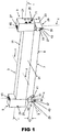
FIG. 1 illustrates a perspective view of a printing head in accordance with one embodiment of the present invention; -
FIG. 2 illustrates a perspective view of one end deflector unit of the printing head ofFIG. 1 ; -
FIG. 3 illustrates an exploded perspective view of the end deflector unit ofFIG. 2 ; -
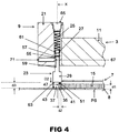
FIG. 4 illustrates a fragmentary part-sectional view (along section I-I inFIG. 1 ) of the printing head ofFIG. 1 , in a printing operation; and -
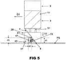
FIG. 5 illustrates a fragmentary part-sectional view (along section II-II inFIG. 1 ) of the printing head ofFIG. 1 , in a printing operation; -
FIG. 6 illustrates a printing head in accordance with another embodiment of the present invention; -
FIG. 7 illustrates a printing head in accordance with a further embodiment of the present invention; -
FIG. 8 illustrates a modified deflector for the printing heads ofFIGs. 1 and6 ; and -
FIG. 9 illustrates another modified deflector for the printing heads ofFIGs. 1 and6 . - The printing head comprises a
support 3, which is attached to a screen printing machine (not illustrated), aprinting blade 7 which is attached to thesupport 3, and first and secondend deflector units 9, which are attached to opposite ends of thesupport 3 to prevent print medium passing laterally beyond the respective ends of theprinting blade 7 during a printing operation. - In this embodiment the print medium is a paste, such as a solder paste.
- In this embodiment the
support 3 comprises anelongate member 11 to which theprinting blade 7 is attached. - In this embodiment the
printing blade 7 has a first,lower edge 8 which contacts a printing screen PS in a printing operation, and theprinting blade 7 depends downwardly from thesupport 3 to engage the printing screen PS, with a forwardly-inclined relation so as to create amain roll 15 of print medium, having an effective diameter of approximately d1, forwardly of theprinting blade 7 in a direction of printing D1, at the junction of theprinting blade 7 and the printing screen PS. - In this embodiment the
printing blade 7 comprises a squeegee blade. - In this embodiment the
end deflector units 9 each comprise abody 21 which is attached to a respective one of the ends of thesupport 3, adeflector 23 which is movably disposed to thebody 21 for a range of travel along a first, substantially vertical axis X and is disposed adjacent a respective one of the ends of theprinting blade 7 so as to contain the print medium within the lateral extent of theprinting blade 7, and abiasing element 25 which acts to bias thedeflector 23 in a downward direction D2 along the first axis X. - In this embodiment the
biasing element 25 is a compression spring. - In this configuration, with the
deflector 23 being movably coupled to thesupport 3, different pressures, which are applied to theprinting blade 7 in various printing operations, can be accommodated, thereby providing that thedeflectors 23 are self-adjusting and avoiding coining of the printing screen PS. - In this embodiment the
body 21 includes aguide recess 27, here an elongate bore, which receives acounterpart guide member 31 of thedeflector 23, as will be described in more detail hereinbelow. The guide recess 27 comprises two sections, a first, lower section in which theguide member 31 is accommodated, and a second, upper section in which thebiasing element 25 is accommodated. The lower section is preferably of non-circular cross-section, which acts to prevent rotation of theguide member 31, and hencedeflector 23, relative to thebody 21. The upper section is preferably of circular cross-section, for accommodating and allowing compression and extension of the compressionspring biasing element 25. It will be noted that this difference in cross-sections prevents thebiasing element 25 from falling out of thebody 21 if thedeflector 23 is removed therefrom. The two sections are aligned and connected, such that the distal end of theguide member 31, i.e. that end which extends furthest intoguide recess 27, contacts thebiasing element 25 and is thereby biased in a downward direction. In this way thedeflector 23 is biased towards the printing screen in use. - In this embodiment the
biasing element 25 is held captive by afixing 65, here a screw fixing, which completely closes the upper section end ofguide recess 27. - In this embodiment the
body 21 includes alateral bore 28, arranged generally orthogonally to the length of the guide recess 27 and in communication therewith, for receiving anengagement member 71, as will be described in more detail hereinbelow. - In this embodiment the
deflector 23 includes adeflector member 29 which engages a surface of the printing screen PS in a printing operation, and aguide member 31, here an elongate shaft, which is counterpart to theguide recess 27 and is slidingly-disposed within theguide recess 27, such that thedeflector 23 is constrained to move along the first axis X in relation to thebody 21 along its range of travel. The cross-sectional shape and dimension of theguide member 31 conforms closely to that of the guide recess 27, which prevents paste or adhesive from entering theguide recess 27, thus preventing contamination. - In this embodiment the
deflector member 29 has a first,engagement surface 35 which engages the printing screen PS in a printing operation, and a second, inwardly-facingsurface 37 which extends from theengagement surface 35 and flares or tapers laterally outwardly in the direction of printing D1. - In this embodiment the
first surface 35 is a substantially planar surface. - In this embodiment the
first surface 35 is profiled or textured, in the manner of tyre tracks, which promotes the transfer of any print medium at thefirst surface 35 laterally inwardly towards theprinting blade 7. - In this embodiment the
second surface 37 is a substantially planar surface. - In another embodiment the
second surface 37 could be a curved or arcuate surface. - In this embodiment the
second surface 37 has a first,rear edge 41 and a second, forward edge 43, and a chord between theedges - In this embodiment the angle β is 32 degrees.
- In one embodiment the angle β is less than 45 degrees.
- In another embodiment the angle β is less than 40 degrees.
- In a further embodiment the angle β is less than 35 degrees.
- In one embodiment the angle β is at least 20 degrees.
- In another embodiment the angle β is at least 25 degrees.
- In a further embodiment the angle β is at least 30 degrees.
- In this embodiment the
second surface 37 extends substantially perpendicular to thecontact edge 8 of theprinting blade 7, here substantially parallel to the first axis X, in a substantially-vertical direction. - With this configuration, second, subsidiary rolls 47 of the print medium are developed at the
respective deflectors 23, having an effective diameter of approximately d2, smaller than diameter d1, which act to return the print medium which passes outwardly of the respective ends of theprinting blade 7 back into themain roll 15 of print medium with little disturbance to the uniformity of themain roll 15 of print medium. - In this embodiment the
deflector member 29 includes a third, downwardly-facingsurface 51 which joins thesecond surface 37 at a distance d3 from thelower surface 35 thereof. - In this embodiment the distance d3 is 8 mm.
- In one embodiment the distance d3 is at least 5 mm.
- In one embodiment the distance d3 is at most 20 mm.
- In one embodiment the distance d3 is at most 15 mm.
- In one embodiment the distance d3 is at most 10 mm.
- In this embodiment the junction of the second and
third surfaces - In this embodiment the junction of the second and
third surfaces - In another embodiment the junction of the second and
third surfaces - In a further embodiment the junction of the second and
third surfaces - In this embodiment the
third surface 51 extends is a substantially flat surface. - In this embodiment the
third surface 51 extends in substantially perpendicular relation to thesecond surface 37. - In an alternative embodiment the
third surface 51 could be an arcuate or curved surface. - The
third surface 51 acts to prevent upward movement of the paste in use. This helps to prevent paste from entering theguide recess 27 at its lower end. Furthermore, the combination ofthird surface 51 and the angledsecond surface 37 acts to constrain the paste to create therolls 47, having a height approximately equal to d3, during the printing operation. This constrains the paste, reducing wastage and simplifying re-use. - In this embodiment the
guide member 31 includes arecess 55, here an elongate slot which extends axially along theguide member 31, which defines first and second limit stops 57, 59. Eachbody 21 of respectiveend deflector units 9 further comprises adetent 67, which extends into therecess 55 in theguide member 31 to define the limit of travel of thedeflector 23 along the first axis X by engagement with the limit stops 57, 59 of therecess 55. - In this embodiment, the
detent 67 is provided by anengagement member 71, which is disposed in thebore 28 in thebody 21. - In this embodiment the
engagement member 71 takes the form of a screw, which is threadedly engaged in thebore 28 and completely closes the same. This arrangement allows the position of thedetent 67 with respect to thebody 21 andrecess 55 to be adjusted by rotation of theengagement member 71 within thebore 28, whereby thedetent 67 may be adjusted to provide sufficient engagement with the end stops 57, 59 to delimit the travel of thedeflector 23 along the first axis X, such that thedetent 67 is captively located within therecess 55. - In this embodiment the
guide member 31 includes agroove 61 which extends axially along theguide member 31 from therecess 55 to the distal end thereof, that is the end opposite to thedeflector member 29. - In this embodiment the
groove 61 is a V-shaped groove. - By suitable adjustment of
detent 67 by rotation of theengagement member 71, thedetent 67 can be drawn out of therecess 55 by manual application by an operator and along thegroove 61, against the frictional resistance with thegroove 61. - In this way, the
groove 61 allows thedeflector 23 to be fitted to and removed from thebody 21 without requiring any tools, with thegroove 61 being shaped and/or sized to allow an operator manually to overcome the frictional resistance with thedetent 67. With this configuration, an operator can readily change thedeflectors 23, such as for cleaning or replacement. This design also enables different types of deflector to be fitted in a modular fashion, for example to interchange between deflectors more suitable for paste application and deflectors more suitable for adhesive application, or to allow separate deflectors for leaded and lead-free paste. Furthermore, the inclusion ofgroove 61 on only one side of theguide member 31 prevents the guide member being inserted by an operator into thebody 21 in an incorrect orientation. - It will be apparent that with the above-described configuration, the biasing
element 25 is located internally of, and wholly enclosed within, thebody 21, throughout the deflector's range of travel, and that paste or adhesive, or indeed any other potential contaminant, is prevented from contaminating the biasingelement 25. In particular, no paste may enter theguide recess 27 at its lower opening due to the close conformance of the first section's cross-section with the cross-section of theguide member 31 and the barrier effect provided bythird surface 51, no paste may enter theguide recess 27 at its upper opening due to the closure by fixing 65, and no paste may enter theguide recess 27 via lateral bore 28 due to the closure byengagement member 71. -
FIG. 6 illustrates a printing head in accordance with another embodiment of the present invention. - The printing head of this embodiment is very similar to that of the above-described embodiment, and thus, in order to avoid unnecessary duplication of description, only the differences will be described in detail, with like parts being designated by like reference signs.
- The printing head of this embodiment differs from that of the above-described embodiment in that the
support 3, theprinting blade 7 and theend deflectors 9 are formed as an integral unit. -
FIG. 7 illustrates a printing head in accordance with a further embodiment of the present invention. - The printing head of this embodiment is quite similar to that of the first-described embodiment, and thus, in order to avoid unnecessary duplication of description, only the differences will be described in detail, with like parts being designated by like reference signs.
- The printing head of this embodiment differs in that the
deflector members 29 omit the second andthird surfaces - Although the omission of the second and
third surfaces deflector members 29 does not allow for the formation of the subsidiary rolls 47 of the print medium at the lateral ends of themain roll 15 of the print medium, thedeflector members 29 still advantageously are self-adjusting, independent of the pressure as applied to theprinting blade 7, thereby preventing coining of the printing screen PS. - This embodiment has particular application to print medium in the form of glues and inks.
- Finally, it will be understood that the present invention has been described in its preferred embodiments and can be modified in many different ways without departing from the invention as defined by the scope of the appended claims.
- For example, in one embodiment, as illustrated in
FIG. 8 , thedeflector member 29 could include a raised,elongate projection 81, which is inclined substantially in parallel relation to theprinting blade 7, and acts to reduce the pressure of the print medium at the junction of thesecond surface 37 and theprinting blade 7. This helps to reduce the formation of "snail trails", i.e. thin trails of paste left in the wake of theprinting blade 7 during the printing operation. - In this embodiment the
projection 81 has the form of a ridge or bead, optionally a rounded ridge or bead. - Although illustrated in relation to the
deflectors 23 ofFIGs. 1 and6 , theprojection 81 could have equal application to the embodiment ofFIG. 7 . - For example, in another embodiment, as illustrated in
FIG. 9 , thedeflector 23 could include an inwardly-projectingmember 91 at a rear, trailing edge in the direction of printing D1, which is located rearwardly of theprinting blade 7 and includes asurface 93 which acts to transfer any print medium which remains on the printing screen PS after traversal of theprint head 3 laterally inwardly into the printing region of the printing screen PS. This also helps to reduce the formation of "snail trails". - Although illustrated in relation to the
deflectors 23 ofFIGs. 1 and6 , the inwardly-projectingmember 91 could have equal application to the embodiment ofFIG. 7 .
Claims (15)
- A deflector unit for use with a printing blade in printing a print medium through a printing screen, the deflector unit comprising:a body which is disposable adjacent a respective one of the ends of a printing blade; a deflector which is movably disposed to the body for a range of travel along a first axis and acts to contain print medium within a lateral extent of the printing blade; and a biasing element which acts to bias the deflector from the body along the first axis; wherein the biasing element is wholly enclosed within the body throughout the range of travel of the deflector.
- The deflector unit of claim 1, wherein the deflector includes a guide member, and the body includes a guide channel in which the guide member is slidingly disposed, such that the deflector is constrained to move along the first axis in relation to the body.
- The deflector unit of claim 2, wherein the guide member comprises an elongate shaft and the guide recess comprises an elongate bore.
- The deflector unit of either of claims 2 and 3, wherein the biasing element engages a distal end of the guide member.
- The deflector unit of any of claims 2 to 4, wherein the guide member includes a recess, optionally an elongate slot extending axially along the guide member, which defines first and second limit stops, and the body includes a detent which is located captively within the recess, whereby the limit stops define a limit of travel of the deflector along the first axis.
- The deflector unit of claim 5, wherein the guide member includes a groove which extends substantially axially along the guide member from the recess to a distal end thereof, optionally the groove is a V-shaped groove, wherein the groove allows the deflector to be fitted to and removed from the body without requiring any tools, with the groove being shaped and/or sized to allow an operator manually to overcome frictional resistance with the detent.
- A deflector for use with a printing blade during a printing operation of printing a print medium through a printing screen to contain print medium within a lateral extent of the printing blade, wherein the deflector includes a deflector member, which has a first, engagement surface which engages a surface of the printing screen, a second, inwardly-facing surface which extends from the engagement surface and flares or tapers laterally outwardly in a first direction of printing, and a third, downwardly-facing surface which joins the second surface at a junction which is spaced at a distance from the first surface.
- The deflector of claim 7, wherein the second and third surfaces act to develop a subsidiary roll of the print medium during the printing operation, which subsidiary roll has an effective diameter which is smaller than an effective diameter of the print medium of a main roll of the print medium at the printing blade.
- The deflector of any of claims 7 to 8, wherein the first surface is profiled or textured, to promote the transfer of any print medium at the first surface laterally inwardly towards the printing blade.
- The deflector of any of claims 7 to 9, wherein the deflector member includes an elongate projection or recess, optionally in the form of a ridge or bead, which is inclined substantially in parallel relation to the lateral edge of the printing blade and acts to reduce a pressure of the print medium at the junction of the deflector member and the printing blade in use.
- The deflector of any of claims 7 to 10, wherein the deflector includes an inwardly-projecting member at a rear, trailing edge in the first direction of printing, which is located rearwardly of the printing blade and includes a surface which acts to transfer any print medium which remains on the printing screen laterally inwardly into a printing region of the printing screen in use.
- A deflector for use with a printing blade in printing a print medium through a printing screen to contain print medium within a lateral extent of the printing blade, wherein the deflector includes a deflector member which includes an elongate projection or recess, which is inclined substantially in parallel relation to the lateral edge of the printing blade and acts to reduce a pressure of the print medium at the junction of the deflector member and the printing blade in use.
- The deflector of claim 12, wherein the projection or recess has the form of a ridge or bead.
- The deflector unit of any of claims 1 to 6, wherein the deflector comprises a deflector of any of claims 7 to 13.
- A printing head, comprising:a support to which a printing blade is attachable; andfirst and second deflector units or deflectors of any of claims 1 to 14 which are disposed adjacent respective ones of the lateral ends of the printing blade.
Applications Claiming Priority (1)
| Application Number | Priority Date | Filing Date | Title |
|---|---|---|---|
| GBGB1610668.4A GB201610668D0 (en) | 2016-06-17 | 2016-06-17 | End deflectors for printing screens |
Publications (3)
| Publication Number | Publication Date |
|---|---|
| EP3257673A2 true EP3257673A2 (en) | 2017-12-20 |
| EP3257673A3 EP3257673A3 (en) | 2018-02-21 |
| EP3257673B1 EP3257673B1 (en) | 2025-03-26 |
Family
ID=56895049
Family Applications (1)
| Application Number | Title | Priority Date | Filing Date |
|---|---|---|---|
| EP17001027.6A Active EP3257673B1 (en) | 2016-06-17 | 2017-06-16 | End deflectors for printing blades |
Country Status (9)
| Country | Link |
|---|---|
| US (1) | US10773513B2 (en) |
| EP (1) | EP3257673B1 (en) |
| JP (1) | JP6626856B2 (en) |
| KR (1) | KR101963112B1 (en) |
| CN (1) | CN107521217B (en) |
| GB (1) | GB201610668D0 (en) |
| MY (1) | MY187288A (en) |
| SG (1) | SG10201704387WA (en) |
| TW (1) | TWI656978B (en) |
Families Citing this family (5)
| Publication number | Priority date | Publication date | Assignee | Title |
|---|---|---|---|---|
| JP7776725B2 (en) * | 2021-05-18 | 2025-11-27 | ミネベアパワーデバイス株式会社 | Squeegee |
| CN113844163A (en) * | 2021-09-10 | 2021-12-28 | 东莞市九方电子设备有限公司 | Printing machine scraper device |
| KR102828272B1 (en) * | 2022-07-27 | 2025-07-04 | 주식회사 이에스이 | Printed circuit board squeegee solder guide |
| CN119677637A (en) * | 2022-10-07 | 2025-03-21 | 株式会社富士 | Scraper device |
| WO2024171285A1 (en) * | 2023-02-14 | 2024-08-22 | ヤマハ発動機株式会社 | Printer and solder rolling method |
Family Cites Families (17)
| Publication number | Priority date | Publication date | Assignee | Title |
|---|---|---|---|---|
| JPH04189142A (en) | 1990-11-21 | 1992-07-07 | Sharp Corp | Solder protrusion preventing apparatus of paste solder printer |
| JP2927054B2 (en) | 1991-07-11 | 1999-07-28 | 松下電器産業株式会社 | Screen printing equipment |
| JP3019617B2 (en) | 1992-07-24 | 2000-03-13 | 松下電器産業株式会社 | Cream solder screen printing equipment |
| US6142070A (en) | 1999-04-08 | 2000-11-07 | M&R Printing Equipment, Inc. | Ink deflector for squeegee on printing machine |
| JP2004034638A (en) | 2002-07-08 | 2004-02-05 | Matsushita Electric Ind Co Ltd | Screen printing equipment |
| JP2006248170A (en) | 2005-03-14 | 2006-09-21 | P-One:Kk | Side guard for screen printing |
| GB2458313B (en) * | 2008-03-13 | 2012-05-23 | Dek Int Gmbh | Print head assembly, screen printing system and method |
| KR101180632B1 (en) | 2010-10-04 | 2012-09-18 | 주식회사이에스이 | Squeegee clearance adjusting device of screen printer |
| CN202053666U (en) | 2011-04-25 | 2011-11-30 | 汤志 | Scraper of printing machine |
| JP2013123891A (en) | 2011-12-16 | 2013-06-24 | Panasonic Corp | Screen printing equipment |
| CN202608228U (en) | 2012-06-04 | 2012-12-19 | 汤志 | SMT printing machine scraper |
| CN103895335A (en) | 2012-12-28 | 2014-07-02 | 鸿富锦精密工业(深圳)有限公司 | Scraper device |
| KR101471958B1 (en) | 2013-08-16 | 2014-12-11 | (주)영하이테크 | Manufacturing mathod of cap plate for secondary batteries having vent structure and using cap plate of it |
| JP6123076B2 (en) * | 2013-11-12 | 2017-05-10 | パナソニックIpマネジメント株式会社 | Screen printing apparatus and electronic component mounting system |
| JP6340589B2 (en) | 2014-05-26 | 2018-06-13 | パナソニックIpマネジメント株式会社 | Screen printing device |
| TWM503062U (en) * | 2014-12-30 | 2015-06-11 | Universal Global Scient Ind Co | Printing machine blade baffle structure and printer scraper |
| CN204451491U (en) | 2014-12-30 | 2015-07-08 | 环胜电子(深圳)有限公司 | Printing machine scraper baffle arrangement and printing machine scraper |
-
2016
- 2016-06-17 GB GBGB1610668.4A patent/GB201610668D0/en not_active Ceased
-
2017
- 2017-05-22 US US15/601,028 patent/US10773513B2/en active Active
- 2017-05-23 TW TW106116939A patent/TWI656978B/en active
- 2017-05-29 MY MYPI2017000812A patent/MY187288A/en unknown
- 2017-05-30 SG SG10201704387WA patent/SG10201704387WA/en unknown
- 2017-06-05 KR KR1020170069506A patent/KR101963112B1/en active Active
- 2017-06-15 CN CN201710450561.5A patent/CN107521217B/en active Active
- 2017-06-16 JP JP2017118369A patent/JP6626856B2/en active Active
- 2017-06-16 EP EP17001027.6A patent/EP3257673B1/en active Active
Also Published As
| Publication number | Publication date |
|---|---|
| US20170361601A1 (en) | 2017-12-21 |
| CN107521217B (en) | 2020-10-16 |
| JP6626856B2 (en) | 2019-12-25 |
| JP2017222168A (en) | 2017-12-21 |
| EP3257673A3 (en) | 2018-02-21 |
| EP3257673B1 (en) | 2025-03-26 |
| KR20170142882A (en) | 2017-12-28 |
| SG10201704387WA (en) | 2018-01-30 |
| US10773513B2 (en) | 2020-09-15 |
| CN107521217A (en) | 2017-12-29 |
| TW201800266A (en) | 2018-01-01 |
| TWI656978B (en) | 2019-04-21 |
| MY187288A (en) | 2021-09-19 |
| KR101963112B1 (en) | 2019-03-29 |
| GB201610668D0 (en) | 2016-08-03 |
Similar Documents
| Publication | Publication Date | Title |
|---|---|---|
| EP3257673B1 (en) | End deflectors for printing blades | |
| DE2550790C2 (en) | Stripping device for slideways on machine tools | |
| EP0374092A1 (en) | Inking unit for a printing machine | |
| EP0521295A1 (en) | Shaver head, especially the razor blade unit of a wet razor | |
| DE3338323A1 (en) | DEVICE FOR COATING CONTINUOUS MATERIALS | |
| DE3043234A1 (en) | INKBOX FOR A PRINTING MACHINE | |
| DE2523240C2 (en) | Wiper blade for the windshield wiper on a curved windshield | |
| DE102011056829A1 (en) | Adjustable wrench | |
| DE4213660C2 (en) | Short inking unit for a web-fed rotary printing press | |
| DE1277081B (en) | Device for the production of coating edges | |
| EP0893200B1 (en) | Wiper device | |
| DE602004003766T2 (en) | Blade tensioning device for jigsaw | |
| EP0008483A1 (en) | Hair cutter, in particular for dry-shavers | |
| DE3109501A1 (en) | DEVICE FOR OPENING ENVELOPES OR THE LIKE | |
| DE69328268T2 (en) | Cleaning member for use in an ink jet device | |
| DE2213019C2 (en) | Handle that can be coupled with a razor blade unit | |
| EP0594536A1 (en) | Segmented ductor knife | |
| DE2319871A1 (en) | WINDSHIELD WIPERS | |
| DE102007009881B4 (en) | Squeegee ink fountain | |
| DE3106176A1 (en) | Ruler for drawing lines and/or measuring, cutting or applying templates or drawing instruments | |
| EP0052195B1 (en) | Ink fountain for a printing machine | |
| EP0286692B1 (en) | Apparatus for cleaning plane surfaces | |
| DE10119098B4 (en) | paintbox | |
| DE10052520A1 (en) | Spacer for use in squeegee for cleaning windows protrudes beyond side of cleaning strip and by smaller distance beyond edge of strip | |
| CH662783A5 (en) | ROLLER ADJUSTMENT IN A TYPEWRITER OR A PRINTER. |
Legal Events
| Date | Code | Title | Description |
|---|---|---|---|
| PUAI | Public reference made under article 153(3) epc to a published international application that has entered the european phase |
Free format text: ORIGINAL CODE: 0009012 |
|
| STAA | Information on the status of an ep patent application or granted ep patent |
Free format text: STATUS: THE APPLICATION HAS BEEN PUBLISHED |
|
| AK | Designated contracting states |
Kind code of ref document: A2 Designated state(s): AL AT BE BG CH CY CZ DE DK EE ES FI FR GB GR HR HU IE IS IT LI LT LU LV MC MK MT NL NO PL PT RO RS SE SI SK SM TR |
|
| AX | Request for extension of the european patent |
Extension state: BA ME |
|
| PUAL | Search report despatched |
Free format text: ORIGINAL CODE: 0009013 |
|
| AK | Designated contracting states |
Kind code of ref document: A3 Designated state(s): AL AT BE BG CH CY CZ DE DK EE ES FI FR GB GR HR HU IE IS IT LI LT LU LV MC MK MT NL NO PL PT RO RS SE SI SK SM TR |
|
| AX | Request for extension of the european patent |
Extension state: BA ME |
|
| RIC1 | Information provided on ipc code assigned before grant |
Ipc: B41F 15/42 20060101AFI20180115BHEP Ipc: B05C 17/06 20060101ALI20180115BHEP |
|
| STAA | Information on the status of an ep patent application or granted ep patent |
Free format text: STATUS: REQUEST FOR EXAMINATION WAS MADE |
|
| 17P | Request for examination filed |
Effective date: 20180817 |
|
| RBV | Designated contracting states (corrected) |
Designated state(s): AL AT BE BG CH CY CZ DE DK EE ES FI FR GB GR HR HU IE IS IT LI LT LU LV MC MK MT NL NO PL PT RO RS SE SI SK SM TR |
|
| STAA | Information on the status of an ep patent application or granted ep patent |
Free format text: STATUS: EXAMINATION IS IN PROGRESS |
|
| 17Q | First examination report despatched |
Effective date: 20201009 |
|
| R17C | First examination report despatched (corrected) |
Effective date: 20201009 |
|
| RAP3 | Party data changed (applicant data changed or rights of an application transferred) |
Owner name: ASMPT SMT SINGAPORE PTE. LTD |
|
| P01 | Opt-out of the competence of the unified patent court (upc) registered |
Effective date: 20230530 |
|
| RAP3 | Party data changed (applicant data changed or rights of an application transferred) |
Owner name: ASMPT SMT SINGAPORE PTE. LTD. |
|
| GRAP | Despatch of communication of intention to grant a patent |
Free format text: ORIGINAL CODE: EPIDOSNIGR1 |
|
| STAA | Information on the status of an ep patent application or granted ep patent |
Free format text: STATUS: GRANT OF PATENT IS INTENDED |
|
| INTG | Intention to grant announced |
Effective date: 20241121 |
|
| GRAS | Grant fee paid |
Free format text: ORIGINAL CODE: EPIDOSNIGR3 |
|
| GRAA | (expected) grant |
Free format text: ORIGINAL CODE: 0009210 |
|
| STAA | Information on the status of an ep patent application or granted ep patent |
Free format text: STATUS: THE PATENT HAS BEEN GRANTED |
|
| AK | Designated contracting states |
Kind code of ref document: B1 Designated state(s): AL AT BE BG CH CY CZ DE DK EE ES FI FR GB GR HR HU IE IS IT LI LT LU LV MC MK MT NL NO PL PT RO RS SE SI SK SM TR |
|
| REG | Reference to a national code |
Ref country code: GB Ref legal event code: FG4D |
|
| REG | Reference to a national code |
Ref country code: CH Ref legal event code: EP |
|
| REG | Reference to a national code |
Ref country code: DE Ref legal event code: R096 Ref document number: 602017088501 Country of ref document: DE |
|
| REG | Reference to a national code |
Ref country code: IE Ref legal event code: FG4D |
|
| PG25 | Lapsed in a contracting state [announced via postgrant information from national office to epo] |
Ref country code: RS Free format text: LAPSE BECAUSE OF FAILURE TO SUBMIT A TRANSLATION OF THE DESCRIPTION OR TO PAY THE FEE WITHIN THE PRESCRIBED TIME-LIMIT Effective date: 20250626 |
|
| PG25 | Lapsed in a contracting state [announced via postgrant information from national office to epo] |
Ref country code: FI Free format text: LAPSE BECAUSE OF FAILURE TO SUBMIT A TRANSLATION OF THE DESCRIPTION OR TO PAY THE FEE WITHIN THE PRESCRIBED TIME-LIMIT Effective date: 20250326 |
|
| REG | Reference to a national code |
Ref country code: LT Ref legal event code: MG9D |
|
| PG25 | Lapsed in a contracting state [announced via postgrant information from national office to epo] |
Ref country code: NO Free format text: LAPSE BECAUSE OF FAILURE TO SUBMIT A TRANSLATION OF THE DESCRIPTION OR TO PAY THE FEE WITHIN THE PRESCRIBED TIME-LIMIT Effective date: 20250626 |
|
| PG25 | Lapsed in a contracting state [announced via postgrant information from national office to epo] |
Ref country code: HR Free format text: LAPSE BECAUSE OF FAILURE TO SUBMIT A TRANSLATION OF THE DESCRIPTION OR TO PAY THE FEE WITHIN THE PRESCRIBED TIME-LIMIT Effective date: 20250326 |
|
| PG25 | Lapsed in a contracting state [announced via postgrant information from national office to epo] |
Ref country code: LV Free format text: LAPSE BECAUSE OF FAILURE TO SUBMIT A TRANSLATION OF THE DESCRIPTION OR TO PAY THE FEE WITHIN THE PRESCRIBED TIME-LIMIT Effective date: 20250326 |
|
| PG25 | Lapsed in a contracting state [announced via postgrant information from national office to epo] |
Ref country code: GR Free format text: LAPSE BECAUSE OF FAILURE TO SUBMIT A TRANSLATION OF THE DESCRIPTION OR TO PAY THE FEE WITHIN THE PRESCRIBED TIME-LIMIT Effective date: 20250627 Ref country code: BG Free format text: LAPSE BECAUSE OF FAILURE TO SUBMIT A TRANSLATION OF THE DESCRIPTION OR TO PAY THE FEE WITHIN THE PRESCRIBED TIME-LIMIT Effective date: 20250326 |
|
| REG | Reference to a national code |
Ref country code: NL Ref legal event code: MP Effective date: 20250326 |
|
| PG25 | Lapsed in a contracting state [announced via postgrant information from national office to epo] |
Ref country code: NL Free format text: LAPSE BECAUSE OF FAILURE TO SUBMIT A TRANSLATION OF THE DESCRIPTION OR TO PAY THE FEE WITHIN THE PRESCRIBED TIME-LIMIT Effective date: 20250326 |
|
| PG25 | Lapsed in a contracting state [announced via postgrant information from national office to epo] |
Ref country code: SE Free format text: LAPSE BECAUSE OF FAILURE TO SUBMIT A TRANSLATION OF THE DESCRIPTION OR TO PAY THE FEE WITHIN THE PRESCRIBED TIME-LIMIT Effective date: 20250326 |
|
| REG | Reference to a national code |
Ref country code: AT Ref legal event code: MK05 Ref document number: 1778682 Country of ref document: AT Kind code of ref document: T Effective date: 20250326 |
|
| PG25 | Lapsed in a contracting state [announced via postgrant information from national office to epo] |
Ref country code: SM Free format text: LAPSE BECAUSE OF FAILURE TO SUBMIT A TRANSLATION OF THE DESCRIPTION OR TO PAY THE FEE WITHIN THE PRESCRIBED TIME-LIMIT Effective date: 20250326 |
|
| PG25 | Lapsed in a contracting state [announced via postgrant information from national office to epo] |
Ref country code: PT Free format text: LAPSE BECAUSE OF FAILURE TO SUBMIT A TRANSLATION OF THE DESCRIPTION OR TO PAY THE FEE WITHIN THE PRESCRIBED TIME-LIMIT Effective date: 20250728 Ref country code: ES Free format text: LAPSE BECAUSE OF FAILURE TO SUBMIT A TRANSLATION OF THE DESCRIPTION OR TO PAY THE FEE WITHIN THE PRESCRIBED TIME-LIMIT Effective date: 20250326 |
|
| PG25 | Lapsed in a contracting state [announced via postgrant information from national office to epo] |
Ref country code: PL Free format text: LAPSE BECAUSE OF FAILURE TO SUBMIT A TRANSLATION OF THE DESCRIPTION OR TO PAY THE FEE WITHIN THE PRESCRIBED TIME-LIMIT Effective date: 20250326 |
|
| PG25 | Lapsed in a contracting state [announced via postgrant information from national office to epo] |
Ref country code: AT Free format text: LAPSE BECAUSE OF FAILURE TO SUBMIT A TRANSLATION OF THE DESCRIPTION OR TO PAY THE FEE WITHIN THE PRESCRIBED TIME-LIMIT Effective date: 20250326 |
|
| PG25 | Lapsed in a contracting state [announced via postgrant information from national office to epo] |
Ref country code: EE Free format text: LAPSE BECAUSE OF FAILURE TO SUBMIT A TRANSLATION OF THE DESCRIPTION OR TO PAY THE FEE WITHIN THE PRESCRIBED TIME-LIMIT Effective date: 20250326 |
|
| PG25 | Lapsed in a contracting state [announced via postgrant information from national office to epo] |
Ref country code: RO Free format text: LAPSE BECAUSE OF FAILURE TO SUBMIT A TRANSLATION OF THE DESCRIPTION OR TO PAY THE FEE WITHIN THE PRESCRIBED TIME-LIMIT Effective date: 20250326 |
|
| PG25 | Lapsed in a contracting state [announced via postgrant information from national office to epo] |
Ref country code: SK Free format text: LAPSE BECAUSE OF FAILURE TO SUBMIT A TRANSLATION OF THE DESCRIPTION OR TO PAY THE FEE WITHIN THE PRESCRIBED TIME-LIMIT Effective date: 20250326 |
|
| PG25 | Lapsed in a contracting state [announced via postgrant information from national office to epo] |
Ref country code: IS Free format text: LAPSE BECAUSE OF FAILURE TO SUBMIT A TRANSLATION OF THE DESCRIPTION OR TO PAY THE FEE WITHIN THE PRESCRIBED TIME-LIMIT Effective date: 20250726 |
|
| REG | Reference to a national code |
Ref country code: DE Ref legal event code: R097 Ref document number: 602017088501 Country of ref document: DE |
|
| PG25 | Lapsed in a contracting state [announced via postgrant information from national office to epo] |
Ref country code: DK Free format text: LAPSE BECAUSE OF FAILURE TO SUBMIT A TRANSLATION OF THE DESCRIPTION OR TO PAY THE FEE WITHIN THE PRESCRIBED TIME-LIMIT Effective date: 20250326 |
|
| PG25 | Lapsed in a contracting state [announced via postgrant information from national office to epo] |
Ref country code: CZ Free format text: LAPSE BECAUSE OF FAILURE TO SUBMIT A TRANSLATION OF THE DESCRIPTION OR TO PAY THE FEE WITHIN THE PRESCRIBED TIME-LIMIT Effective date: 20250326 |
|
| REG | Reference to a national code |
Ref country code: CH Ref legal event code: H13 Free format text: ST27 STATUS EVENT CODE: U-0-0-H10-H13 (AS PROVIDED BY THE NATIONAL OFFICE) Effective date: 20260127 |
|
| PG25 | Lapsed in a contracting state [announced via postgrant information from national office to epo] |
Ref country code: MC Free format text: LAPSE BECAUSE OF FAILURE TO SUBMIT A TRANSLATION OF THE DESCRIPTION OR TO PAY THE FEE WITHIN THE PRESCRIBED TIME-LIMIT Effective date: 20250326 |
|
| PLBE | No opposition filed within time limit |
Free format text: ORIGINAL CODE: 0009261 |
|
| STAA | Information on the status of an ep patent application or granted ep patent |
Free format text: STATUS: NO OPPOSITION FILED WITHIN TIME LIMIT |
|
| REG | Reference to a national code |
Ref country code: CH Ref legal event code: L10 Free format text: ST27 STATUS EVENT CODE: U-0-0-L10-L00 (AS PROVIDED BY THE NATIONAL OFFICE) Effective date: 20260211 |
|
| PG25 | Lapsed in a contracting state [announced via postgrant information from national office to epo] |
Ref country code: LU Free format text: LAPSE BECAUSE OF NON-PAYMENT OF DUE FEES Effective date: 20250616 |
|
| REG | Reference to a national code |
Ref country code: BE Ref legal event code: MM Effective date: 20250630 |
|
| 26N | No opposition filed |
Effective date: 20260105 |
|
| PG25 | Lapsed in a contracting state [announced via postgrant information from national office to epo] |
Ref country code: IE Free format text: LAPSE BECAUSE OF NON-PAYMENT OF DUE FEES Effective date: 20250616 |
|
| PG25 | Lapsed in a contracting state [announced via postgrant information from national office to epo] |
Ref country code: BE Free format text: LAPSE BECAUSE OF NON-PAYMENT OF DUE FEES Effective date: 20250630 |
|
| PG25 | Lapsed in a contracting state [announced via postgrant information from national office to epo] |
Ref country code: CH Free format text: LAPSE BECAUSE OF NON-PAYMENT OF DUE FEES Effective date: 20250630 |
|
| PG25 | Lapsed in a contracting state [announced via postgrant information from national office to epo] |
Ref country code: LT Free format text: LAPSE BECAUSE OF FAILURE TO SUBMIT A TRANSLATION OF THE DESCRIPTION OR TO PAY THE FEE WITHIN THE PRESCRIBED TIME-LIMIT Effective date: 20250326 |
|
| PGFP | Annual fee paid to national office [announced via postgrant information from national office to epo] |
Ref country code: GB Payment date: 20260625 Year of fee payment: 10 |
|
| PGFP | Annual fee paid to national office [announced via postgrant information from national office to epo] |
Ref country code: IT Payment date: 20260623 Year of fee payment: 10 |
|
| PGFP | Annual fee paid to national office [announced via postgrant information from national office to epo] |
Ref country code: DE Payment date: 20260622 Year of fee payment: 10 |
|
| PGFP | Annual fee paid to national office [announced via postgrant information from national office to epo] |
Ref country code: FR Payment date: 20260626 Year of fee payment: 10 |
|
| PG25 | Lapsed in a contracting state [announced via postgrant information from national office to epo] |
Ref country code: CY Free format text: LAPSE BECAUSE OF FAILURE TO SUBMIT A TRANSLATION OF THE DESCRIPTION OR TO PAY THE FEE WITHIN THE PRESCRIBED TIME-LIMIT Effective date: 20250326 |