EP3257529A1 - Rigid sterilization container with a locking mechanism for a replaceable filter assembly - Google Patents
Rigid sterilization container with a locking mechanism for a replaceable filter assembly Download PDFInfo
- Publication number
- EP3257529A1 EP3257529A1 EP17175697.6A EP17175697A EP3257529A1 EP 3257529 A1 EP3257529 A1 EP 3257529A1 EP 17175697 A EP17175697 A EP 17175697A EP 3257529 A1 EP3257529 A1 EP 3257529A1
- Authority
- EP
- European Patent Office
- Prior art keywords
- clip
- sterilization container
- biasing member
- container according
- cavity
- Prior art date
- Legal status (The legal status is an assumption and is not a legal conclusion. Google has not performed a legal analysis and makes no representation as to the accuracy of the status listed.)
- Granted
Links
Images






Classifications
-
- A—HUMAN NECESSITIES
- A61—MEDICAL OR VETERINARY SCIENCE; HYGIENE
- A61L—METHODS OR APPARATUS FOR STERILISING MATERIALS OR OBJECTS IN GENERAL; DISINFECTION, STERILISATION OR DEODORISATION OF AIR; CHEMICAL ASPECTS OF BANDAGES, DRESSINGS, ABSORBENT PADS OR SURGICAL ARTICLES; MATERIALS FOR BANDAGES, DRESSINGS, ABSORBENT PADS OR SURGICAL ARTICLES
- A61L2/00—Disinfection or sterilisation of materials or objects, in general; Accessories therefor
- A61L2/26—Accessories
-
- A—HUMAN NECESSITIES
- A61—MEDICAL OR VETERINARY SCIENCE; HYGIENE
- A61B—DIAGNOSIS; SURGERY; IDENTIFICATION
- A61B50/00—Containers, covers, furniture or holders specially adapted for surgical or diagnostic appliances or instruments, e.g. sterile covers
- A61B50/30—Containers specially adapted for packaging, protecting, dispensing, collecting or disposing of surgical or diagnostic appliances or instruments
-
- B—PERFORMING OPERATIONS; TRANSPORTING
- B01—PHYSICAL OR CHEMICAL PROCESSES OR APPARATUS IN GENERAL
- B01D—SEPARATION
- B01D46/00—Filters or filtering processes specially modified for separating dispersed particles from gases or vapours
- B01D46/0002—Casings; Housings; Frame constructions
- B01D46/0005—Mounting of filtering elements within casings, housings or frames
-
- E—FIXED CONSTRUCTIONS
- E05—LOCKS; KEYS; WINDOW OR DOOR FITTINGS; SAFES
- E05B—LOCKS; ACCESSORIES THEREFOR; HANDCUFFS
- E05B65/00—Locks or fastenings for special use
-
- A—HUMAN NECESSITIES
- A61—MEDICAL OR VETERINARY SCIENCE; HYGIENE
- A61B—DIAGNOSIS; SURGERY; IDENTIFICATION
- A61B50/00—Containers, covers, furniture or holders specially adapted for surgical or diagnostic appliances or instruments, e.g. sterile covers
- A61B2050/005—Containers, covers, furniture or holders specially adapted for surgical or diagnostic appliances or instruments, e.g. sterile covers with a lid or cover
- A61B2050/0058—Containers, covers, furniture or holders specially adapted for surgical or diagnostic appliances or instruments, e.g. sterile covers with a lid or cover closable by translation
- A61B2050/006—Containers, covers, furniture or holders specially adapted for surgical or diagnostic appliances or instruments, e.g. sterile covers with a lid or cover closable by translation perpendicular to the lid plane, e.g. by a downward movement
-
- A—HUMAN NECESSITIES
- A61—MEDICAL OR VETERINARY SCIENCE; HYGIENE
- A61B—DIAGNOSIS; SURGERY; IDENTIFICATION
- A61B50/00—Containers, covers, furniture or holders specially adapted for surgical or diagnostic appliances or instruments, e.g. sterile covers
- A61B2050/005—Containers, covers, furniture or holders specially adapted for surgical or diagnostic appliances or instruments, e.g. sterile covers with a lid or cover
- A61B2050/0066—Containers, covers, furniture or holders specially adapted for surgical or diagnostic appliances or instruments, e.g. sterile covers with a lid or cover with additional sealing means, e.g. O-ring
-
- A—HUMAN NECESSITIES
- A61—MEDICAL OR VETERINARY SCIENCE; HYGIENE
- A61B—DIAGNOSIS; SURGERY; IDENTIFICATION
- A61B50/00—Containers, covers, furniture or holders specially adapted for surgical or diagnostic appliances or instruments, e.g. sterile covers
- A61B2050/005—Containers, covers, furniture or holders specially adapted for surgical or diagnostic appliances or instruments, e.g. sterile covers with a lid or cover
- A61B2050/0067—Types of closures or fasteners
-
- A—HUMAN NECESSITIES
- A61—MEDICAL OR VETERINARY SCIENCE; HYGIENE
- A61B—DIAGNOSIS; SURGERY; IDENTIFICATION
- A61B50/00—Containers, covers, furniture or holders specially adapted for surgical or diagnostic appliances or instruments, e.g. sterile covers
- A61B50/30—Containers specially adapted for packaging, protecting, dispensing, collecting or disposing of surgical or diagnostic appliances or instruments
- A61B2050/3011—Containers specially adapted for packaging, protecting, dispensing, collecting or disposing of surgical or diagnostic appliances or instruments having carrying handles
-
- A—HUMAN NECESSITIES
- A61—MEDICAL OR VETERINARY SCIENCE; HYGIENE
- A61L—METHODS OR APPARATUS FOR STERILISING MATERIALS OR OBJECTS IN GENERAL; DISINFECTION, STERILISATION OR DEODORISATION OF AIR; CHEMICAL ASPECTS OF BANDAGES, DRESSINGS, ABSORBENT PADS OR SURGICAL ARTICLES; MATERIALS FOR BANDAGES, DRESSINGS, ABSORBENT PADS OR SURGICAL ARTICLES
- A61L2103/00—Materials or objects being the target of disinfection or sterilisation
- A61L2103/15—Laboratory, medical or dentistry appliances, e.g. catheters or sharps
-
- A—HUMAN NECESSITIES
- A61—MEDICAL OR VETERINARY SCIENCE; HYGIENE
- A61L—METHODS OR APPARATUS FOR STERILISING MATERIALS OR OBJECTS IN GENERAL; DISINFECTION, STERILISATION OR DEODORISATION OF AIR; CHEMICAL ASPECTS OF BANDAGES, DRESSINGS, ABSORBENT PADS OR SURGICAL ARTICLES; MATERIALS FOR BANDAGES, DRESSINGS, ABSORBENT PADS OR SURGICAL ARTICLES
- A61L2202/00—Aspects relating to methods or apparatus for disinfecting or sterilising materials or objects
- A61L2202/10—Apparatus features
- A61L2202/12—Apparatus for isolating biocidal substances from the environment
- A61L2202/122—Chambers for sterilisation
-
- Y—GENERAL TAGGING OF NEW TECHNOLOGICAL DEVELOPMENTS; GENERAL TAGGING OF CROSS-SECTIONAL TECHNOLOGIES SPANNING OVER SEVERAL SECTIONS OF THE IPC; TECHNICAL SUBJECTS COVERED BY FORMER USPC CROSS-REFERENCE ART COLLECTIONS [XRACs] AND DIGESTS
- Y10—TECHNICAL SUBJECTS COVERED BY FORMER USPC
- Y10T—TECHNICAL SUBJECTS COVERED BY FORMER US CLASSIFICATION
- Y10T292/00—Closure fasteners
- Y10T292/08—Bolts
- Y10T292/0801—Multiple
- Y10T292/0834—Sliding
-
- Y—GENERAL TAGGING OF NEW TECHNOLOGICAL DEVELOPMENTS; GENERAL TAGGING OF CROSS-SECTIONAL TECHNOLOGIES SPANNING OVER SEVERAL SECTIONS OF THE IPC; TECHNICAL SUBJECTS COVERED BY FORMER USPC CROSS-REFERENCE ART COLLECTIONS [XRACs] AND DIGESTS
- Y10—TECHNICAL SUBJECTS COVERED BY FORMER USPC
- Y10T—TECHNICAL SUBJECTS COVERED BY FORMER US CLASSIFICATION
- Y10T292/00—Closure fasteners
- Y10T292/08—Bolts
- Y10T292/0801—Multiple
- Y10T292/0834—Sliding
- Y10T292/0836—Operating means
-
- Y—GENERAL TAGGING OF NEW TECHNOLOGICAL DEVELOPMENTS; GENERAL TAGGING OF CROSS-SECTIONAL TECHNOLOGIES SPANNING OVER SEVERAL SECTIONS OF THE IPC; TECHNICAL SUBJECTS COVERED BY FORMER USPC CROSS-REFERENCE ART COLLECTIONS [XRACs] AND DIGESTS
- Y10—TECHNICAL SUBJECTS COVERED BY FORMER USPC
- Y10T—TECHNICAL SUBJECTS COVERED BY FORMER US CLASSIFICATION
- Y10T292/00—Closure fasteners
- Y10T292/08—Bolts
- Y10T292/0801—Multiple
- Y10T292/0834—Sliding
- Y10T292/0836—Operating means
- Y10T292/0846—Rigid
-
- Y—GENERAL TAGGING OF NEW TECHNOLOGICAL DEVELOPMENTS; GENERAL TAGGING OF CROSS-SECTIONAL TECHNOLOGIES SPANNING OVER SEVERAL SECTIONS OF THE IPC; TECHNICAL SUBJECTS COVERED BY FORMER USPC CROSS-REFERENCE ART COLLECTIONS [XRACs] AND DIGESTS
- Y10—TECHNICAL SUBJECTS COVERED BY FORMER USPC
- Y10T—TECHNICAL SUBJECTS COVERED BY FORMER US CLASSIFICATION
- Y10T292/00—Closure fasteners
- Y10T292/08—Bolts
- Y10T292/096—Sliding
-
- Y—GENERAL TAGGING OF NEW TECHNOLOGICAL DEVELOPMENTS; GENERAL TAGGING OF CROSS-SECTIONAL TECHNOLOGIES SPANNING OVER SEVERAL SECTIONS OF THE IPC; TECHNICAL SUBJECTS COVERED BY FORMER USPC CROSS-REFERENCE ART COLLECTIONS [XRACs] AND DIGESTS
- Y10—TECHNICAL SUBJECTS COVERED BY FORMER USPC
- Y10T—TECHNICAL SUBJECTS COVERED BY FORMER US CLASSIFICATION
- Y10T292/00—Closure fasteners
- Y10T292/08—Bolts
- Y10T292/096—Sliding
- Y10T292/0961—Multiple head
- Y10T292/0962—Operating means
-
- Y—GENERAL TAGGING OF NEW TECHNOLOGICAL DEVELOPMENTS; GENERAL TAGGING OF CROSS-SECTIONAL TECHNOLOGIES SPANNING OVER SEVERAL SECTIONS OF THE IPC; TECHNICAL SUBJECTS COVERED BY FORMER USPC CROSS-REFERENCE ART COLLECTIONS [XRACs] AND DIGESTS
- Y10—TECHNICAL SUBJECTS COVERED BY FORMER USPC
- Y10T—TECHNICAL SUBJECTS COVERED BY FORMER US CLASSIFICATION
- Y10T292/00—Closure fasteners
- Y10T292/08—Bolts
- Y10T292/096—Sliding
- Y10T292/0969—Spring projected
-
- Y—GENERAL TAGGING OF NEW TECHNOLOGICAL DEVELOPMENTS; GENERAL TAGGING OF CROSS-SECTIONAL TECHNOLOGIES SPANNING OVER SEVERAL SECTIONS OF THE IPC; TECHNICAL SUBJECTS COVERED BY FORMER USPC CROSS-REFERENCE ART COLLECTIONS [XRACs] AND DIGESTS
- Y10—TECHNICAL SUBJECTS COVERED BY FORMER USPC
- Y10T—TECHNICAL SUBJECTS COVERED BY FORMER US CLASSIFICATION
- Y10T292/00—Closure fasteners
- Y10T292/08—Bolts
- Y10T292/096—Sliding
- Y10T292/0969—Spring projected
- Y10T292/097—Operating means
-
- Y—GENERAL TAGGING OF NEW TECHNOLOGICAL DEVELOPMENTS; GENERAL TAGGING OF CROSS-SECTIONAL TECHNOLOGIES SPANNING OVER SEVERAL SECTIONS OF THE IPC; TECHNICAL SUBJECTS COVERED BY FORMER USPC CROSS-REFERENCE ART COLLECTIONS [XRACs] AND DIGESTS
- Y10—TECHNICAL SUBJECTS COVERED BY FORMER USPC
- Y10T—TECHNICAL SUBJECTS COVERED BY FORMER US CLASSIFICATION
- Y10T292/00—Closure fasteners
- Y10T292/08—Bolts
- Y10T292/096—Sliding
- Y10T292/0969—Spring projected
- Y10T292/097—Operating means
- Y10T292/0995—Push or pull rod
-
- Y—GENERAL TAGGING OF NEW TECHNOLOGICAL DEVELOPMENTS; GENERAL TAGGING OF CROSS-SECTIONAL TECHNOLOGIES SPANNING OVER SEVERAL SECTIONS OF THE IPC; TECHNICAL SUBJECTS COVERED BY FORMER USPC CROSS-REFERENCE ART COLLECTIONS [XRACs] AND DIGESTS
- Y10—TECHNICAL SUBJECTS COVERED BY FORMER USPC
- Y10T—TECHNICAL SUBJECTS COVERED BY FORMER US CLASSIFICATION
- Y10T292/00—Closure fasteners
- Y10T292/08—Bolts
- Y10T292/096—Sliding
- Y10T292/0969—Spring projected
- Y10T292/097—Operating means
- Y10T292/0997—Rigid
Definitions
- the present invention relates to containers, and more specifically, to sterilization containers that can be used to sterilize and store medical devices, for example.
- Sterilization containers include air permeable filter assemblies that allow filtered ambient air to enter and exit the container during and after the sterilization process. After a use, it may be desirable to re-use the container. However, it would be desirable to be able to replace the filter media in the filter assemblies to ensure a clean transfer of sufficient air through the filter assemblies.
- the sterilization devices and systems may include a sterilization container, one or more filters, one or more filter retaining plates, and one or more clips or locks designed to secure the filters and/or plates to the sterilization container.
- the methods may include steps for assembling and/or utilizing the sterilization container, for example, in an autoclave process.
- a sterilization container may include a pan, lid, filter retaining plates, filter retainer clips, seals, and handles.
- the pan contains holes that permit the passage of air, moist heat/steam, or other autoclave gases into the container.
- the retaining plates attach to the pan over these perforated areas to hold filter media.
- the sterilization container includes a locking mechanism comprising a shell and a first clip slidingly inserted inside the shell.
- the first clip has a first locking member.
- a second clip is slidingly inserted inside the shell.
- the second clip has a second locking member.
- a biasing member has a first end connected to the first clip and a second end connected to the second clip such that the biasing member biases the first clip and the second clip such that the first locking member is biased toward the second locking member.
- the sterilization container includes a locking mechanism comprising a shell having a first opening, a second opening, and a cavity extending between the first opening and the second opening.
- a first clip has a first button extending through the first opening, a first elongate base extending distally from the first button, a first spacer extending from the first base, a first surface extending upwardly from the first spacer. The first surface has a first cavity formed at a first proximal end thereof.
- a first biasing member support is disposed between the first elongate base and the first surface.
- a second clip is identical to the first clip.
- a biasing member has a first end connected to the first biasing member support and a second end connected to a second biasing member support.
- the sterilization container includes a locking assembly comprising a mounting post and a locking mechanism.
- the locking mechanism comprises a shell and a first clip slidingly inserted inside the shell.
- the first clip has a first locking member disposed on a first side of the mounting post.
- a second clip is slidingly inserted inside the shell.
- the second clip is identical to the first clip and is disposed on an opposing side of the mounting post.
- a biasing member has a first end connected to the first clip and a second end connected to the second clip such that the biasing member biases the first clip and the second clip into engagement with the mounting post.
- exemplary is used herein to mean serving as an example, instance, or illustration. Any aspect or design described herein as "exemplary” is not necessarily to be construed as preferred or advantageous over other aspects or designs. Rather, use of the word exemplary is intended to present concepts in a concrete fashion.
- figure numbers and/or figure reference labels in the claims is intended to identify one or more possible embodiments of the claimed subject matter in order to facilitate the interpretation of the claims. Such use is not to be construed as necessarily limiting the scope of those claims to the embodiments shown in the corresponding figures.
- Couple refers to any manner known in the art or later developed of joining or connecting two or more elements directly or indirectly to one another, and the interposition of one or more additional elements is contemplated, although not required. Conversely, the terms “directly coupled,” “directly connected,” etc., imply the absence of such additional elements.
- the present disclosure provides embodiments of autoclavable containers that can be used to sterilize and store medical devices and/or medical instruments, for example.
- the containers may be especially configured to hold product graphic cases during a steam sterilization cycle, for example, as an alternative to using sterilization wraps.
- Exemplary specifications for inventive containers may include, for example: permitting penetration of a sterilizing medium, e.g., steam sterilization, and allow for drying of moisture left behind by the sterilization within standard autoclave times; having a minimum filter area configured for effective sterilization of the devices and instruments positioned within a graphic case within the sterilization device, e.g., a minimum filter area of 176 square inches; allowing one or more product graphic cases to fit with their handles in an upright position; utilizing standard filter sizes and tamper proof locks; weighing not more than 11 pounds for the largest size; and being stackable.
- a sterilizing medium e.g., steam sterilization
- Such containers also include filter assemblies that allow for the passage of a sterilization medium, such as steam and air, into and out of the containers during and after a sterilization process.
- a sterilization medium such as steam and air
- the filter assemblies may be the only locations on the container that allow the passage of moist heat. This ensures that the contents within the container remain sterile once removed from the autoclave.
- a filter assembly may include a filter assembly clip that securely retains the filter assembly on the container, yet can be readily released to remove the filter assembly from the container for replacement of its filter media.
- Container 100 provides an alternate to traditional sterilization wraps for hospitals.
- Some benefits of container 100 over the prior art container include a lightweight design that weighs less than some other known containers; a lid design that allows the handles of a case (not shown) that is placed inside container 100 to remain upright, allow the surgical staff to easily lift the case out of container 100 in an operating room environment; the bottom of the pan mirrors the shape of the lid, allowing a second container 100 to be easily stacked on a first container 100 for storage; accommodation of standard filters and tamper locks, thereby allowing hospitals to easily integrate container 100 into the sterile processing departments; and a proven latch design for longevity.
- Container 100 is a generally parallelepiped structure having longitudinal front and rear sides 102, 104, respectively, lateral right and left sides 106, 108, respectively, and a bottom pan 110. Sides 102, 104, 106, 108 and bottom pan 110 define a cavity 111 into which objects, such as product graphic cases (not shown) to be stored within container 100.
- a removable lid 120 is provided to cover container 100.
- Bottom pan 110 includes a rim 112 that extends around a perimeter thereof, defining a projection 114 extending downwardly from bottom pan 110.
- lid 120 includes a rim 122 defining an indentation 124 extending downwardly from a top surface 126 of lid 120 such that projection 114 of one container 100 can fit into indentation 124 of another container 100, allowing a plurality of containers 100 to be stacked, one on top of another.
- Each indentation 124 includes two sets of a plurality of openings 128 arranged in a generally annular pattern. Openings 128 allow air passage through lid 120 and to/from filter assemblies 130 mounted on an interior 129 of lid 120.
- a screw hole 132 is centered within each plurality of openings 128 to allow for the passage of a securing member, such as a screw 134, to secure a mounting post 135 to lid 120.
- Filter assemblies 130 are sized so as not to project significantly above projection 114 so as not to take up a significant amount of space within cavity 111.
- projection 114 includes two sets of a plurality of openings 136 arranged in a generally annular pattern. Openings 136 allow air passage through bottom pan 110 and to/from filter assemblies 130 mounted on an interior 138 of bottom pan 110.
- a screw hole 140 is centered within each plurality of openings 136 to allow for the passage of a securing member, such as a screw 142, to secure a mounting post 144 to bottom pan 110.
- filter assembly 130 includes a generally circular retainer disk 150 having an outer perimeter 152, a central hub 154, and a plurality of spokes 156 connecting central hub 154 to outer perimeter 152.
- a filter media 158 is disposed between adjacent spokes 156.
- Retainer disk 150 can be sized to hold standard 7.5 inch diameter filter media offered by various manufacturers.
- Outer perimeter 152 includes a recessed channel 160 sized to receive and retain an outer seal 162.
- Outer seal 162 is annular in shape and includes an outer lip 164 and an inner lip 166.
- Outer seal 162 can be constructed from silicone, rubber, or other suitable sealing material.
- Hub 154 includes a recessed surface 168 that is sized to accept an inner seal 170.
- Hub 154 includes a central opening 172 that is sized to allow mounting post 135, 144 to extend therethrough.
- inner seal 170 includes a central opening 174 that is also sized to allow mounting post 135, 144 to extend therethrough.
- Inner seal 170 can be constructed form silicone, rubber, or other suitable material.
- mounting post 135 is shown.
- mounting post 144 is identical to mounting post 135, so only mounting post 135 will be discussed.
- Mounting post 135 includes a connected end 189 and a free end 192.
- Connected end 189 includes a threaded blind passage 194 into which screw 134 is inserted.
- Free end 192 includes a frusto-conical head 195 mounted on a tapered support 196.
- Tapered support 196 extends underneath frusto-conical head 195 such that a rim 198 is formed on the underside of head 195.
- Hub 154 also includes a pair of through-openings 176 that are sized to receive securing members, such as screws 178. Screws 178 are used to secure a locking mechanism 179 to hub 154.
- locking mechanism 179 includes two opposing buttons 182, 184 that, when compressed toward each other, release locking mechanism 179 and, when released, secure locking mechanism 179.
- button 180 is generally parallelepiped in shape, with curved lateral sides, forming an oblong cross-section. Those skilled in the art, however, will recognize that button 182 can be other shapes as well.
- Buttons 182, 184 are contained in a shell 186 having an elongate cavity 188.
- shell 186 includes a pair of diametrically opposed recesses 187 on either side of cavity 188 that allow for screws 178 (shown in FIG. 10 ) to secure shell 186 to hub 154.
- a first clip 190 and a second clip 191 are slidingly disposed inside cavity 188 for longitudinal motion in cavity 188.
- first clip 190 is identical to second clip 191.
- First clip 190 and second clip 191 are disposed in shell 186 such that first clip 190 and second clip 191 travel in opposing directions, as will be discussed in more detail later herein.
- shell 186 On a first side of cavity 188, shell 186 comprises a first activation opening 194 through which button 182 on first clip 190 slidably extends. Similarly, on a second side of cavity 188, shell 186 comprises a second activation opening 196, diametrically opposite from first activation opening 194, such that cavity 188 extends between first activation opening 194 and second activation opening 196, through which button 184 on second clip 191 slidably extends.
- First clip 190 is shown in FIGS. 16-21 . Because, in an exemplary embodiment, first clip 190 and second clip 191 are identical, only first clip 190 will be described.
- Clip 190 has a body 199 having a proximal end 200 connected to button 182 and a distal end 202 that includes locking member 203.
- proximal is a location on clip 190, 191 closer to button 180, 182, respectively
- distal is a location on clip 190, 191 farther from button 180, 182, respectively.
- Body 199 includes an elongate base 204 connected to and extending distally from button 182.
- Base 204 extends along only one side of a longitudinal axis 205 and includes an elongate void 207 (shown in FIG. 20 ).
- An opposing side of longitudinal axis 205 is devoid of a body to provide room for second clip 191.
- a spacer 206 extends from base 204 and, referring to FIGS. 22 and 24 , a surface 208 extends from spacer 206.
- Surface 208 is a planar surface having a cavity 209 formed at a proximal end 211 thereof such that surface 208 and cavity 209 form locking member 203.
- Cavity 209 is arcuate in shape and is beveled for engagement with tapered support 196 on mounting post 135.
- Cavity 209 extends partially around mounting post 135 when clip 190 is engaged with mounting post 135.
- a first arcuate passage 217 extends between base 204, spacer 206, and surface 208.
- First arcuate passage 217 is sized to allow a biasing member, such as a first spring 230, to fit thereinto.
- an opposing side of spacer 206 includes a second arcuate passage 219 that is sized to allow a second spring 232 to fit thereinto.
- a through passage 234 can be formed in spacer 206 between arcuate passages 217, 219. Through passage 234 reduces the amount of material used in body 199 and reduces the weight of body 199, allowing for a smoother operation of clip 190.
- base 204 includes a plurality of ribs 220, 222 that rest in the bottom of shell 186 and allow clip 190 to slide within shell 186 with less friction than if ribs 220, 222 were omitted and base 204 directly engaged and slid within shell 186.
- a first pin passage 240 extends through surface 208, coaxially with a first pin slot 242.
- First pin passage 240 and first pin slot 242 are sized to receive and retain a first biasing member support 245 so that first biasing member support 245 is disposed in first arcuate passage 217 at distal end 202 between elongate base 204 and surface 208.
- a second pin passage 244 extends through surface 208, coaxially with a second pin slot 246.
- Second pin passage 244 and second pin slot 246 are sized to receive and retain a second biasing member support 247 so that second biasing member support 247 is disposed in second arcuate passage 219 at first distal end 202 between elongate base 204 and surface 208.
- clip 190 and clip 191 are identical.
- surface 208 of first clip 190 is coplanar with a corresponding surface 208 of second clip 191.
- Cavity 209 on clip 190 and a corresponding cavity 209 on clip 191 form a locking surface that is used to engage mounting post 135. See FIG. 15 .
- First biasing member 230 has a first end 234 connected to clip 190 at first biasing member support 245 and a second end 236 connected to clip 191 at second biasing member support 247 such that biasing member 230 biases clip 190 and clip 191 so that surface 208 on clip 190 is biased toward surface 208 on clip 191.
- first biasing member 230, as well as second biasing member 232 is a helical spring disposed in first arcuate passage 217 and second arcuate passage 219, respectively, between base 204 and first locking member 203. Biasing members 230, 232 bias locking member 203 on clip 190 and locking member 203 on clip 191 into engagement with mounting post 135. Referring to FIG. 22 , a first portion 240 of biasing member 230 extends through clip 190 and a remaining portion 242 of biasing member 230 extends through clip 191.
- locking mechanism 179 When locking mechanism 179 is attached to hub 154, mounting post 135 is disposed between cavity 209 of clip 190 and cavity 209 of clip 191 wherein, when locking mechanism 179 is in a locked position, as shown in FIG. 13 , surface 208 of first clip 190 and the first surface 208 of second clip 191 engage mounting post 135. Locking mechanism 179 is shown in a locked position in FIGS. 22 and 23 .
- FIGS. 24 and 25 show locking mechanism 179 in an unlocked position.
- This translation extends biasing members 230, 232 between their respective mounting posts 245, 247, storing energy within biasing member 230, 232.
- first and second buttons 182, 184 are released, the energy stored in biasing members 230, 232 is released, compressing biasing members 230, 232, and moving locking members 203 of each clip 190, 191 into engagement with mounting post 135.
- rim 122 of lid 120 includes a recessed channel 210 extending therearound.
- Channel 210 is sized to accept a lid lock 212 on right side 106 and a similar lid lock 212 on left side 108 of container 100.
- a reinforcing member 213 is located over rim 122 and has a first end extending into channel 210 and a second end extending outwardly of lid 120 to the end of rim 122.
- Reinforcing member 213 can be constructed from aluminum, stainless steel, or other suitable material.
- Rim 122 also includes a convex portion 214 that is sized to accept and retain a seal 218.
- Seal 218 seals the space between container 100 and lid 120 when lid is secured to container 100.
- Seal 218 can be constructed from silicone, rubber, or other suitable material.
- lid lock 212 includes a latching portion 250 having a free end 252 that engages reinforcing member 213, as shown in Fig. 14 .
- An opposing end of latching portion 250 is cammed to a lever 264 at a pivot 266 such that, as lever 264 is pushed downward to the position shown in FIG. 2 , free end 252 biases downwardly against reinforcing member 213, securing lid 120 to container 100.
- lever 264 is pushed upward, releasing the camming action at pivot 266 and raising free end 252 above rim 122 so that free end 252 can pivot about pivot 266 and away from lid 120.
- a handle assembly 260 is pivotally connected to side wall 106.
- Handle assembly 260 includes a frame 262 that is connected directly to sidewall 106, such as by rivets, chemical bonding, or other suitable connection mechanism.
- a channel 264 is connected to frame 262.
- Channel 264 supports a pivoting end 266 of a handle 268.
- Pivoting end 266 of handle 268 is wider than lid lock 212 so that handle 268 can extend around an outer perimeter of lid lock 212, as shown in FIG. 4 .
- Handle 268 is generally "U-shaped", with ends that extend loosely into channel 264 so that handle 268 can pivot about 180 degrees within channel 264 from the position shown in FIG. 4 to a position where handle 268 extends below lid lock 212.
- Also provided are methods for assembling and using the sterilization systems and kits including the sterilization container, cases to be positioned within the sterilization container, and medical devices and instruments configured to be received within the graphic cases and sterilized, for example, using an autoclave process.
Landscapes
- Health & Medical Sciences (AREA)
- Life Sciences & Earth Sciences (AREA)
- Animal Behavior & Ethology (AREA)
- Veterinary Medicine (AREA)
- Surgery (AREA)
- Public Health (AREA)
- General Health & Medical Sciences (AREA)
- Engineering & Computer Science (AREA)
- Molecular Biology (AREA)
- Medical Informatics (AREA)
- Heart & Thoracic Surgery (AREA)
- Biomedical Technology (AREA)
- Nuclear Medicine, Radiotherapy & Molecular Imaging (AREA)
- Epidemiology (AREA)
- Chemical & Material Sciences (AREA)
- Chemical Kinetics & Catalysis (AREA)
- Infusion, Injection, And Reservoir Apparatuses (AREA)
- Medical Preparation Storing Or Oral Administration Devices (AREA)
- Apparatus For Disinfection Or Sterilisation (AREA)
Abstract
Description
- This application claims priority to provisional application No.
62/350,362, filed June 15, 2016 - The present invention relates to containers, and more specifically, to sterilization containers that can be used to sterilize and store medical devices, for example.
- Sterilization containers include air permeable filter assemblies that allow filtered ambient air to enter and exit the container during and after the sterilization process. After a use, it may be desirable to re-use the container. However, it would be desirable to be able to replace the filter media in the filter assemblies to ensure a clean transfer of sufficient air through the filter assemblies.
- Accordingly, there exists a need for a sterilization container that includes filter assemblies that can be readily removed and replaced if necessary.
- To meet this and other needs, devices, systems, and methods of sterilization are provided. The sterilization devices and systems may include a sterilization container, one or more filters, one or more filter retaining plates, and one or more clips or locks designed to secure the filters and/or plates to the sterilization container. The methods may include steps for assembling and/or utilizing the sterilization container, for example, in an autoclave process.
- According to one embodiment, a sterilization container may include a pan, lid, filter retaining plates, filter retainer clips, seals, and handles. The pan contains holes that permit the passage of air, moist heat/steam, or other autoclave gases into the container. The retaining plates attach to the pan over these perforated areas to hold filter media.
- In one embodiment, the sterilization container includes a locking mechanism comprising a shell and a first clip slidingly inserted inside the shell. The first clip has a first locking member. A second clip is slidingly inserted inside the shell. The second clip has a second locking member. A biasing member has a first end connected to the first clip and a second end connected to the second clip such that the biasing member biases the first clip and the second clip such that the first locking member is biased toward the second locking member.
- In another embodiment, the sterilization container includes a locking mechanism comprising a shell having a first opening, a second opening, and a cavity extending between the first opening and the second opening. A first clip has a first button extending through the first opening, a first elongate base extending distally from the first button, a first spacer extending from the first base, a first surface extending upwardly from the first spacer. The first surface has a first cavity formed at a first proximal end thereof. A first biasing member support is disposed between the first elongate base and the first surface. A second clip is identical to the first clip. A biasing member has a first end connected to the first biasing member support and a second end connected to a second biasing member support.
- In still another embodiment, the sterilization container includes a locking assembly comprising a mounting post and a locking mechanism. The locking mechanism comprises a shell and a first clip slidingly inserted inside the shell. The first clip has a first locking member disposed on a first side of the mounting post. A second clip is slidingly inserted inside the shell. The second clip is identical to the first clip and is disposed on an opposing side of the mounting post. A biasing member has a first end connected to the first clip and a second end connected to the second clip such that the biasing member biases the first clip and the second clip into engagement with the mounting post.
- This Summary is provided to introduce a selection of concepts in a simplified form that are further described below in the Detailed Description. This Summary is not intended to identify key features or essential features of the claimed subject matter, nor is it intended to be used to limit the scope of the claimed subject matter.
- Other aspects, features, and advantages of the present invention will become more fully apparent from the following detailed description, the appended claims, and the accompanying drawings in which like reference numerals identify similar or identical elements.
-
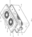
FIG. 1 is a perspective view of a sterilization container according to a first exemplary embodiment; -
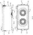
FIG. 2 is a front elevational view of the sterilization container shown inFIG. 1 ; -
FIG. 3 is a top plan view of the sterilization container shown inFIG. 1 ; -
FIG. 4 is a right side elevational view of the sterilization container shown inFIG. 1 ; -
FIG. 5 is a bottom perspective exploded view of a lid used with the container shown inFIG. 1 ; -
FIG. 6 is a top perspective exploded view of the lid shown inFIG. 5 ; -
FIG. 7 is a top perspective exploded view of the container shown inFIG. 1 ; -
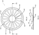
FIG. 8 is a top plan view of a filter assembly used with the container shown inFIG. 1 ; -
FIG. 9 is a side elevational view of the filter assembly shown inFIG. 8 ; -
FIG. 10 is a top exploded view of the filter assembly shown inFIG. 8 ; -
FIG. 11 is a sectional view of the filter assembly taken along lines 11-11 ofFIG. 8 ; -
FIG. 12 is an enlarged view of a seal used with the filter assembly ofFIG. 8 , taken alongenlargement circle 12 shown inFIG. 11 ; -
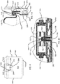
FIG. 13 is an enlarged sectional view of the filter assembly ofFIG. 8 , taken alongenlargement circle 13 shown inFIG. 2 ; -
FIG. 14 is an enlarged sectional view of a lid clip used with the container taken alongenlargement circle 14 ofFIG. 2 ; -
FIG. 15 is an exploded view of an exemplary embodiment of a locking mechanism used to secure the filter assembly ofFIG. 8 onto the container ofFIG. 1 ; -
FIG. 16 is an exploded perspective view of a clip used with the locking mechanism shown inFIG. 15 ; -
FIG. 17 is a bottom plan view of the clip shown inFIG. 16 ; -
FIG. 18 is an end elevation view of the clip shown inFIG. 16 ; -
FIG. 19 is a sectional view of the clip shown inFIG. 16 , taken along lines 19-19 ofFIG. 17 ; -
FIG. 20 is a top plan view of the clip shown inFIG. 16 ; -
FIG. 21 is a sectional view of the clip shown inFIG. 16 , taken along lines 21-21 ofFIG. 20 ; -
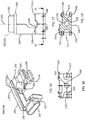
FIG. 22 is a bottom perspective view of the locking mechanism shown inFIG. 15 , without its shell, showing the clips in a latching position; -
FIG. 23 is a top perspective view of the locking mechanism ofFIG. 22 ; -
FIG. 24 is a is a bottom perspective view of the locking mechanism shown inFIG. 15 , without it shell, showing the clips in an unlatching position; and -
FIG. 25 is a top perspective view of the locking mechanism ofFIG. 24 . - In the drawings, like numerals indicate like elements throughout. Certain terminology is used herein for convenience only and is not to be taken as a limitation on the present invention. The terminology includes the words specifically mentioned, derivatives thereof and words of similar import. The embodiments illustrated below are not intended to be exhaustive or to limit the invention to the precise form disclosed. These embodiments are chosen and described to best explain the principle of the invention and its application and practical use and to enable others skilled in the art to best utilize the invention.
- Reference herein to "one embodiment" or "an embodiment" means that a particular feature, structure, or characteristic described in connection with the embodiment can be included in at least one embodiment of the invention. The appearances of the phrase "in one embodiment" in various places in the specification are not necessarily all referring to the same embodiment, nor are separate or alternative embodiments necessarily mutually exclusive of other embodiments. The same applies to the term "implementation."
- As used in this application, the word "exemplary" is used herein to mean serving as an example, instance, or illustration. Any aspect or design described herein as "exemplary" is not necessarily to be construed as preferred or advantageous over other aspects or designs. Rather, use of the word exemplary is intended to present concepts in a concrete fashion.
- Additionally, the term "or" is intended to mean an inclusive "or" rather than an exclusive "or". That is, unless specified otherwise, or clear from context, "X employs A or B" is intended to mean any of the natural inclusive permutations. That is, if X employs A; X employs B; or X employs both A and B, then "X employs A or B" is satisfied under any of the foregoing instances. In addition, the articles "a" and "an" as used in this application and the appended claims should generally be construed to mean "one or more" unless specified otherwise or clear from context to be directed to a singular form.
- Unless explicitly stated otherwise, each numerical value and range should be interpreted as being approximate as if the word "about" or "approximately" preceded the value of the value or range.
- The use of figure numbers and/or figure reference labels in the claims is intended to identify one or more possible embodiments of the claimed subject matter in order to facilitate the interpretation of the claims. Such use is not to be construed as necessarily limiting the scope of those claims to the embodiments shown in the corresponding figures.
- It should be understood that the steps of the exemplary methods set forth herein are not necessarily required to be performed in the order described, and the order of the steps of such methods should be understood to be merely exemplary. Likewise, additional steps may be included in such methods, and certain steps may be omitted or combined, in methods consistent with various embodiments of the present invention.
- Although the elements in the following method claims, if any, are recited in a particular sequence with corresponding labeling, unless the claim recitations otherwise imply a particular sequence for implementing some or all of those elements, those elements are not necessarily intended to be limited to being implemented in that particular sequence.
- Also for purposes of this description, the terms "couple," "coupling," "coupled," "connect," "connecting," or "connected" refer to any manner known in the art or later developed of joining or connecting two or more elements directly or indirectly to one another, and the interposition of one or more additional elements is contemplated, although not required. Conversely, the terms "directly coupled," "directly connected," etc., imply the absence of such additional elements.
- The present disclosure provides embodiments of autoclavable containers that can be used to sterilize and store medical devices and/or medical instruments, for example. The containers may be especially configured to hold product graphic cases during a steam sterilization cycle, for example, as an alternative to using sterilization wraps.
- Exemplary specifications for inventive containers may include, for example: permitting penetration of a sterilizing medium, e.g., steam sterilization, and allow for drying of moisture left behind by the sterilization within standard autoclave times; having a minimum filter area configured for effective sterilization of the devices and instruments positioned within a graphic case within the sterilization device, e.g., a minimum filter area of 176 square inches; allowing one or more product graphic cases to fit with their handles in an upright position; utilizing standard filter sizes and tamper proof locks; weighing not more than 11 pounds for the largest size; and being stackable.
- Such containers also include filter assemblies that allow for the passage of a sterilization medium, such as steam and air, into and out of the containers during and after a sterilization process. When the container is sealed with its lid, the filter assemblies may be the only locations on the container that allow the passage of moist heat. This ensures that the contents within the container remain sterile once removed from the autoclave.
- According to one embodiment, a filter assembly may include a filter assembly clip that securely retains the filter assembly on the container, yet can be readily released to remove the filter assembly from the container for replacement of its filter media.
- Referring to
FIGS. 1-4 , acontainer 100 according to a first exemplary embodiment is shown.Container 100 provides an alternate to traditional sterilization wraps for hospitals. Some benefits ofcontainer 100 over the prior art container include a lightweight design that weighs less than some other known containers; a lid design that allows the handles of a case (not shown) that is placed insidecontainer 100 to remain upright, allow the surgical staff to easily lift the case out ofcontainer 100 in an operating room environment; the bottom of the pan mirrors the shape of the lid, allowing asecond container 100 to be easily stacked on afirst container 100 for storage; accommodation of standard filters and tamper locks, thereby allowing hospitals to easily integratecontainer 100 into the sterile processing departments; and a proven latch design for longevity. -
Container 100 is a generally parallelepiped structure having longitudinal front andrear sides sides bottom pan 110.Sides bottom pan 110 define acavity 111 into which objects, such as product graphic cases (not shown) to be stored withincontainer 100. - Referring to
FIGS. 5 and 6 , aremovable lid 120 is provided to covercontainer 100.Bottom pan 110 includes arim 112 that extends around a perimeter thereof, defining aprojection 114 extending downwardly frombottom pan 110. Similarly,lid 120 includes arim 122 defining anindentation 124 extending downwardly from atop surface 126 oflid 120 such thatprojection 114 of onecontainer 100 can fit intoindentation 124 of anothercontainer 100, allowing a plurality ofcontainers 100 to be stacked, one on top of another. - Each
indentation 124 includes two sets of a plurality ofopenings 128 arranged in a generally annular pattern.Openings 128 allow air passage throughlid 120 and to/fromfilter assemblies 130 mounted on an interior 129 oflid 120. Ascrew hole 132 is centered within each plurality ofopenings 128 to allow for the passage of a securing member, such as ascrew 134, to secure a mountingpost 135 tolid 120.Filter assemblies 130 are sized so as not to project significantly aboveprojection 114 so as not to take up a significant amount of space withincavity 111. - Similarly, referring to
FIG. 7 ,projection 114 includes two sets of a plurality ofopenings 136 arranged in a generally annular pattern.Openings 136 allow air passage throughbottom pan 110 and to/fromfilter assemblies 130 mounted on an interior 138 ofbottom pan 110. Ascrew hole 140 is centered within each plurality ofopenings 136 to allow for the passage of a securing member, such as ascrew 142, to secure a mountingpost 144 tobottom pan 110. - Referring to
FIGS. 8-13 ,filter assembly 130 includes a generallycircular retainer disk 150 having anouter perimeter 152, acentral hub 154, and a plurality ofspokes 156 connectingcentral hub 154 toouter perimeter 152. Afilter media 158 is disposed betweenadjacent spokes 156.Retainer disk 150 can be sized to hold standard 7.5 inch diameter filter media offered by various manufacturers. -
Outer perimeter 152 includes a recessedchannel 160 sized to receive and retain anouter seal 162.Outer seal 162 is annular in shape and includes anouter lip 164 and aninner lip 166.Outer seal 162 can be constructed from silicone, rubber, or other suitable sealing material. -
Hub 154 includes a recessedsurface 168 that is sized to accept aninner seal 170.Hub 154 includes acentral opening 172 that is sized to allow mountingpost inner seal 170 includes acentral opening 174 that is also sized to allow mountingpost Inner seal 170 can be constructed form silicone, rubber, or other suitable material. - Referring specifically to
FIG. 13 , mountingpost 135 is shown. In an exemplary embodiment, mountingpost 144 is identical to mountingpost 135, so only mountingpost 135 will be discussed. Mountingpost 135 includes aconnected end 189 and afree end 192.Connected end 189 includes a threadedblind passage 194 into which screw 134 is inserted.Free end 192 includes a frusto-conical head 195 mounted on atapered support 196.Tapered support 196 extends underneath frusto-conical head 195 such that arim 198 is formed on the underside ofhead 195. -
Hub 154 also includes a pair of through-openings 176 that are sized to receive securing members, such as screws 178.Screws 178 are used to secure alocking mechanism 179 tohub 154. - Referring to
FIGS. 15-25 ,locking mechanism 179 includes two opposingbuttons release locking mechanism 179 and, when released,secure locking mechanism 179. As shown inFIG. 16 ,button 180 is generally parallelepiped in shape, with curved lateral sides, forming an oblong cross-section. Those skilled in the art, however, will recognize thatbutton 182 can be other shapes as well. -
Buttons shell 186 having anelongate cavity 188. As shown inFIG. 15 ,shell 186 includes a pair of diametricallyopposed recesses 187 on either side ofcavity 188 that allow for screws 178 (shown inFIG. 10 ) to secureshell 186 tohub 154. Afirst clip 190 and asecond clip 191 are slidingly disposed insidecavity 188 for longitudinal motion incavity 188. In an exemplary embodiment,first clip 190 is identical tosecond clip 191.First clip 190 andsecond clip 191 are disposed inshell 186 such thatfirst clip 190 andsecond clip 191 travel in opposing directions, as will be discussed in more detail later herein. - On a first side of
cavity 188,shell 186 comprises afirst activation opening 194 through whichbutton 182 onfirst clip 190 slidably extends. Similarly, on a second side ofcavity 188,shell 186 comprises asecond activation opening 196, diametrically opposite fromfirst activation opening 194, such thatcavity 188 extends betweenfirst activation opening 194 andsecond activation opening 196, through whichbutton 184 onsecond clip 191 slidably extends. -
First clip 190 is shown inFIGS. 16-21 . Because, in an exemplary embodiment,first clip 190 andsecond clip 191 are identical, onlyfirst clip 190 will be described. -
Clip 190 has abody 199 having aproximal end 200 connected tobutton 182 and adistal end 202 that includes lockingmember 203. As used herein, the term "proximal" is a location onclip button clip button -
Body 199 includes anelongate base 204 connected to and extending distally frombutton 182.Base 204 extends along only one side of alongitudinal axis 205 and includes an elongate void 207 (shown inFIG. 20 ). An opposing side oflongitudinal axis 205 is devoid of a body to provide room forsecond clip 191. Aspacer 206 extends frombase 204 and, referring toFIGS. 22 and24 , asurface 208 extends fromspacer 206.Surface 208 is a planar surface having acavity 209 formed at aproximal end 211 thereof such thatsurface 208 andcavity 209form locking member 203.Cavity 209 is arcuate in shape and is beveled for engagement with taperedsupport 196 on mountingpost 135.Cavity 209 extends partially around mountingpost 135 whenclip 190 is engaged with mountingpost 135. - A first
arcuate passage 217 extends betweenbase 204,spacer 206, andsurface 208. Firstarcuate passage 217 is sized to allow a biasing member, such as afirst spring 230, to fit thereinto. Similarly, an opposing side ofspacer 206 includes a secondarcuate passage 219 that is sized to allow asecond spring 232 to fit thereinto. Optionally, a throughpassage 234 can be formed inspacer 206 betweenarcuate passages passage 234 reduces the amount of material used inbody 199 and reduces the weight ofbody 199, allowing for a smoother operation ofclip 190. - Referring to
FIG. 16 ,base 204 includes a plurality ofribs shell 186 and allowclip 190 to slide withinshell 186 with less friction than ifribs base 204 directly engaged and slid withinshell 186. - As shown in
FIG. 19 , afirst pin passage 240 extends throughsurface 208, coaxially with afirst pin slot 242.First pin passage 240 andfirst pin slot 242 are sized to receive and retain a firstbiasing member support 245 so that first biasingmember support 245 is disposed in firstarcuate passage 217 atdistal end 202 betweenelongate base 204 andsurface 208. Similarly, asecond pin passage 244 extends throughsurface 208, coaxially with asecond pin slot 246.Second pin passage 244 andsecond pin slot 246 are sized to receive and retain a secondbiasing member support 247 so that second biasingmember support 247 is disposed in secondarcuate passage 219 at firstdistal end 202 betweenelongate base 204 andsurface 208. - As discussed above, in an exemplary embodiment,
clip 190 andclip 191 are identical. When clips 190, 191 are assembled inshell 186,surface 208 offirst clip 190 is coplanar with acorresponding surface 208 ofsecond clip 191.Cavity 209 onclip 190 and acorresponding cavity 209 onclip 191 form a locking surface that is used to engage mountingpost 135. SeeFIG. 15 . - First biasing
member 230 has afirst end 234 connected to clip 190 at first biasingmember support 245 and asecond end 236 connected to clip 191 at second biasingmember support 247 such that biasingmember 230biases clip 190 andclip 191 so thatsurface 208 onclip 190 is biased towardsurface 208 onclip 191. In an exemplary embodiment, first biasingmember 230, as well assecond biasing member 232, is a helical spring disposed in firstarcuate passage 217 and secondarcuate passage 219, respectively, betweenbase 204 and first lockingmember 203. Biasingmembers bias locking member 203 onclip 190 and lockingmember 203 onclip 191 into engagement with mountingpost 135. Referring toFIG. 22 , afirst portion 240 of biasingmember 230 extends throughclip 190 and a remainingportion 242 of biasingmember 230 extends throughclip 191. - When locking
mechanism 179 is attached tohub 154, mountingpost 135 is disposed betweencavity 209 ofclip 190 andcavity 209 ofclip 191 wherein, when lockingmechanism 179 is in a locked position, as shown inFIG. 13 ,surface 208 offirst clip 190 and thefirst surface 208 ofsecond clip 191 engage mountingpost 135.Locking mechanism 179 is shown in a locked position inFIGS. 22 and 23 . - Translation of
first button 182 andsecond button 184 intoshell 186 moves surface 208 ofclip 190 away from mountingpost 135 and towardsecond button 182, as well as moves surface 208 ofclip 191 away from mountingpost 135 and towardfirst button 182, releasinglocking mechanism 179 from mountingpost 135 and allowinglocking mechanism 179 to be removed fromcontainer 100 orlid 120.FIGS. 24 and 25 show locking mechanism 179 in an unlocked position. This translation extends biasingmembers posts member second buttons members members members 203 of eachclip post 135. - Referring back to
FIG. 14 ,rim 122 oflid 120 includes a recessedchannel 210 extending therearound.Channel 210 is sized to accept alid lock 212 onright side 106 and asimilar lid lock 212 onleft side 108 ofcontainer 100. A reinforcingmember 213 is located overrim 122 and has a first end extending intochannel 210 and a second end extending outwardly oflid 120 to the end ofrim 122. Reinforcingmember 213 can be constructed from aluminum, stainless steel, or other suitable material. -
Rim 122 also includes aconvex portion 214 that is sized to accept and retain aseal 218. Seal 218 seals the space betweencontainer 100 andlid 120 when lid is secured tocontainer 100.Seal 218 can be constructed from silicone, rubber, or other suitable material. - Referring back to
FIGS. 2 ,4, and 14 ,lid lock 212 includes a latchingportion 250 having afree end 252 that engages reinforcingmember 213, as shown inFig. 14 . An opposing end of latchingportion 250 is cammed to alever 264 at apivot 266 such that, aslever 264 is pushed downward to the position shown inFIG. 2 ,free end 252 biases downwardly against reinforcingmember 213, securinglid 120 tocontainer 100. To release latchingportion 250,lever 264 is pushed upward, releasing the camming action atpivot 266 and raisingfree end 252 aboverim 122 so thatfree end 252 can pivot aboutpivot 266 and away fromlid 120. - Referring back to
FIG. 14 , ahandle assembly 260 is pivotally connected toside wall 106.Handle assembly 260 includes aframe 262 that is connected directly tosidewall 106, such as by rivets, chemical bonding, or other suitable connection mechanism. Achannel 264 is connected to frame 262.Channel 264 supports a pivotingend 266 of ahandle 268. Pivotingend 266 ofhandle 268 is wider thanlid lock 212 so that handle 268 can extend around an outer perimeter oflid lock 212, as shown inFIG. 4 . Handle 268 is generally "U-shaped", with ends that extend loosely intochannel 264 so that handle 268 can pivot about 180 degrees withinchannel 264 from the position shown inFIG. 4 to a position where handle 268 extends belowlid lock 212. - Also provided are methods for assembling and using the sterilization systems and kits including the sterilization container, cases to be positioned within the sterilization container, and medical devices and instruments configured to be received within the graphic cases and sterilized, for example, using an autoclave process.
- It will be further understood that various changes in the details, materials, and arrangements of the parts which have been described and illustrated in order to explain the nature of this invention may be made by those skilled in the art without departing from the scope of the invention as expressed in the following claims.
Inter alia the invention could be defined also by the following aspects: - 1. A locking mechanism comprising: a shell; a first clip slidingly inserted inside the shell, the first clip having a first locking member; a second clip slidingly inserted inside the shell, the second clip having a second locking member; and a biasing member having a first end connected to the first clip and a second end connected to the second clip such that the biasing member biases the first clip and the second clip so that the first locking member is biased toward the second locking member.
- 2. The locking mechanism according to
aspect 1, wherein the first clip is identical to the second clip. - 3. The locking mechanism according to aspect 2, wherein the first locking member comprises a planar surface having a cavity formed at a proximal end thereof.
- 4. The locking mechanism according to
aspect 1, wherein the shell comprises a first activation opening and wherein the first clip comprises a first button slidably extending through the first activation opening. - 5. The locking mechanism according to aspect 4, wherein the first clip comprises a first body having a first proximal end connected to the button and a first distal end having a first biasing member support.
- 6. The locking mechanism according to aspect 5, wherein the first proximal end comprises a first base and wherein the first distal end further comprises the first locking member
- 7. The locking mechanism according to aspect 6, wherein the biasing member is disposed between the first base and the first locking member.
- 8. The locking mechanism according to aspect 4, wherein the shell comprises an elongate cavity and wherein the first clip and the second clip are disposed inside the cavity.
- 9. A locking mechanism comprising: a shell having a first opening, a second opening, and a cavity extending between the first opening and the second opening; a first clip having: a first button extending through the first opening; a first elongate base extending distally from the first button; a first spacer extending from the first base; a first surface extending upwardly from the first spacer, the first surface having a first cavity formed at a first proximal end thereof; and a first biasing member support disposed between the first elongate base and the first surface; a second clip having: a second button extending through the second opening; a second elongate base extending distally from the second button; a second spacer extending from the second base; a second surface extending upwardly from the second spacer, the second surface having a second cavity formed at a second proximal end thereof; and a second biasing member support disposed between the second elongate base and the second surface; and a biasing member having a first end connected to the first biasing member support and a second end connected to the second biasing member support.
- 10. The locking mechanism according to aspect 9, wherein the biasing member biases the first surface toward the second surface.
- 11. The locking mechanism according to aspect 10, wherein the first cavity and the second cavity form a locking surface.
- 12. The locking mechanism according to aspect 9, wherein the first biasing member is disposed between the first elongate base and the first surface.
- 13. The locking mechanism according to aspect 9, wherein the first surface is coplanar with the second surface.
- 14. The locking mechanism according to aspect 9, wherein the first member is identical to the second member.
- 15. The locking mechanism according to aspect 9, further comprising a mounting post disposed between the first cavity and the second cavity wherein, when the locking mechanism is in a locked position, the first surface and the second surface engage the mounting post.
- 16. A locking assembly comprising: a mounting post; and a locking mechanism comprising: a shell; a first clip slidingly inserted inside the shell, the first clip having a first locking member disposed on a first side of the mounting post; a second clip slidingly inserted inside the shell, the second clip being identical to the first clip and being disposed on an opposing side of the mounting post; and a biasing member having a first end connected to the first clip and a second end connected to the second clip such that the biasing member biases the first locking member and the second locking member into engagement with the mounting post.
- 17. The locking assembly according to aspect 16 wherein the first clip comprises a first button extending outwardly from the shell wherein translation of the first button into the shell moves the first locking member away from the mounting post.
- 18. The locking assembly according to aspect 17, wherein the first clip comprises an elongate body having a first end connected to the button and a second end connected to a biasing support member such that the first end of the biasing member is connected to the biasing support member.
- 19. The locking assembly according to aspect 16, wherein the first locking member has a cavity such that the cavity extends partially around the mounting post when the biasing member biases the first locking member into engagement with the mounting post.
- 20. The locking assembly according to aspect 16, wherein a first portion of the biasing member extends through the first latching member and wherein a remaining portion of the biasing member extends through the second latching member.
Claims (15)
- A sterilization container comprising a locking mechanism for retaining a filter assembly, the locking mechanism comprising:- a shell;- a first clip slidingly inserted inside the shell, the first clip having a first locking member;- a second clip slidingly inserted inside the shell, the second clip having a second locking member; and- a biasing member having a first end connected to the first clip and a second end connected to the second clip such that the biasing member biases the first clip and the second clip so that the first locking member is biased toward the second locking member.
- The sterilization container according to claim 1, wherein the first clip is identical to the second clip.
- The sterilization container according to claim 2, wherein the first locking member comprises a planar surface having a cavity formed at a proximal end thereof.
- The sterilization container according to claim 1, wherein the shell comprises a first activation opening and wherein the first clip comprises a first button slidably extending through the first activation opening.
- The sterilization container according to claim 4, wherein the first clip comprises a first body having a first proximal end connected to the button and a first distal end having a first biasing member support.
- The sterilization container according to claim 5, wherein the first proximal end comprises a first base and wherein the first distal end further comprises the first locking member.
- The sterilization container according to claim 6, wherein the biasing member is disposed between the first base and the first locking member.
- The sterilization container according to claim 4, wherein the shell comprises an elongate cavity and wherein the first clip and the second clip are disposed inside the cavity.
- A sterilization container according to claim 1, wherein:- the shell has a first opening, a second opening, and a cavity extending between the first opening and the second opening;- the first clip has:- a first button extending through the first opening;- a first elongate base extending distally from the first button;- a first spacer extending from the first base;- a first surface extending upwardly from the first spacer, the first surface having a first cavity formed at a first proximal end thereof; and- a first biasing member support disposed between the first elongate base and the first surface;- the second clip has:- a second button extending through the second opening;- a second elongate base extending distally from the second button;- a second spacer extending from the second base;- a second surface extending upwardly from the second spacer, the second surface having a second cavity formed at a second proximal end thereof; and- a second biasing member support disposed between the second elongate base and the second surface; and- the biasing member has the first end connected to the first biasing member support and the second end connected to the second biasing member support.
- The sterilization container according to claim 9, wherein the biasing member biases the first surface toward the second surface.
- The sterilization container according to claim 10, wherein the first cavity and the second cavity form a locking surface.
- The sterilization container according to claim 9, wherein the first biasing member is disposed between the first elongate base and the first surface.
- The sterilization container according to claim 9, wherein the first surface is coplanar with the second surface.
- The sterilization container according to claim 9, wherein the first member is identical to the second member.
- The sterilization container according to claim 9, further comprising a mounting post disposed between the first cavity and the second cavity wherein, when the locking mechanism is in a locked position, the first surface and the second surface engage the mounting post.
Applications Claiming Priority (2)
| Application Number | Priority Date | Filing Date | Title |
|---|---|---|---|
| US201662350362P | 2016-06-15 | 2016-06-15 | |
| US15/399,774 US10772982B2 (en) | 2016-06-15 | 2017-01-06 | Rigid sterilization container with replaceable filter assemblies |
Publications (2)
| Publication Number | Publication Date |
|---|---|
| EP3257529A1 true EP3257529A1 (en) | 2017-12-20 |
| EP3257529B1 EP3257529B1 (en) | 2024-05-15 |
Family
ID=59055084
Family Applications (1)
| Application Number | Title | Priority Date | Filing Date |
|---|---|---|---|
| EP17175697.6A Active EP3257529B1 (en) | 2016-06-15 | 2017-06-13 | Rigid sterilization container with a locking mechanism for a replaceable filter assembly |
Country Status (3)
| Country | Link |
|---|---|
| US (2) | US10772982B2 (en) |
| EP (1) | EP3257529B1 (en) |
| JP (1) | JP7004443B2 (en) |
Cited By (2)
| Publication number | Priority date | Publication date | Assignee | Title |
|---|---|---|---|---|
| WO2023282870A1 (en) * | 2021-07-05 | 2023-01-12 | Aygun Cerrahi Aletler San. Ve Tic. A.S. | A cover for use in sterilization boxes |
| EP4198408A1 (en) * | 2021-12-17 | 2023-06-21 | Carrier Corporation | Filter frame for an air handling unit |
Families Citing this family (6)
| Publication number | Priority date | Publication date | Assignee | Title |
|---|---|---|---|---|
| CA3001013A1 (en) * | 2015-10-05 | 2017-04-13 | Stryker Corporation | Sterilizable enclosure for securing a portable electronic device |
| DE102017120520B4 (en) * | 2017-09-06 | 2026-08-20 | Aesculap Ag | Sterile container with vapor-permeable seal |
| US11786621B2 (en) * | 2019-10-10 | 2023-10-17 | Carefusion 2200, Inc. | Reusable tortuous path filters for sterilization containers |
| DE102020131104A1 (en) * | 2020-11-24 | 2022-05-25 | Aesculap Ag | Sterilization sieve tray with fixing handle |
| KR102630266B1 (en) * | 2023-05-25 | 2024-01-29 | 주식회사 플라즈맵 | Sterilizer Storage Device and Sterilization Device Comprising the Same |
| DE102024108375A1 (en) * | 2024-03-25 | 2025-09-25 | Aesculap Ag | Sterile goods container handling device and method for automatically handling a filter holder of a sterile goods container |
Citations (3)
| Publication number | Priority date | Publication date | Assignee | Title |
|---|---|---|---|---|
| US4796778A (en) * | 1987-03-27 | 1989-01-10 | Aesculap-Werke Ag Vormals Jetter & Scheerer | Locking mechanism |
| US20010020601A1 (en) * | 1998-07-21 | 2001-09-13 | Aesculap Ag & Co. Kg Am Aesculap-Platz | Plate-shaped filter holder for a sterilizing container |
| DE102009013442A1 (en) * | 2009-03-18 | 2010-09-23 | Nopa Instruments Medizintechnik Gmbh | Medical equipment i.e. surgical instrument, sterilizing device, has filter holder detachably connected with catch element at container by clamping elements that are tangentially and linearly adjusted against catch element |
Family Cites Families (35)
| Publication number | Priority date | Publication date | Assignee | Title |
|---|---|---|---|---|
| US597574A (en) * | 1898-01-18 | Tea or coffee pot | ||
| US370331A (en) * | 1887-09-20 | Coffin-fastening device | ||
| USRE21608E (en) * | 1940-10-29 | Night latch | ||
| US630414A (en) * | 1898-12-21 | 1899-08-08 | Sophia Schwartz | Cooking vessel. |
| US662681A (en) * | 1900-04-27 | 1900-11-27 | George W Sigley | Cupboard-latch. |
| US972765A (en) * | 1907-02-25 | 1910-10-11 | Mergott J E Co | Bag-fastener. |
| US907085A (en) * | 1907-09-17 | 1908-12-15 | Ross C Mcnutt | Box-fastener. |
| US1113479A (en) * | 1913-10-27 | 1914-10-13 | Henry C Phipps | Milk-can closure. |
| US1892743A (en) * | 1930-05-13 | 1933-01-03 | David M Wenger | Closure fastener for receptacles |
| US2221110A (en) * | 1937-01-29 | 1940-11-12 | Oscar A Ross | Lock mechanism |
| US2535275A (en) * | 1946-01-28 | 1950-12-26 | Dixon Frank Thomas | Manhole lid clamp |
| US2878389A (en) * | 1954-11-24 | 1959-03-17 | Halsey L Raffman | Cassette |
| JPS5842974Y2 (en) * | 1979-10-05 | 1983-09-29 | 株式会社ニコン | lens cap |
| US4312528A (en) * | 1979-11-07 | 1982-01-26 | Plc Engineering Company Limited | Panic bolt assembly |
| JPS60169622U (en) * | 1984-04-20 | 1985-11-11 | 旭光学工業株式会社 | lens cap |
| US5016926A (en) * | 1988-05-20 | 1991-05-21 | Doskocil Manufacturing Company, Inc. | Latching mechanism |
| US4930819A (en) * | 1988-05-20 | 1990-06-05 | Doskocil Manufacturing Co., Inc. | Latching mechanism |
| US5227074A (en) * | 1991-03-04 | 1993-07-13 | Monarch Products, Inc. | Filter for medical instrument sterilization containers and method for removing moisture and contaminants therefrom |
| JPH04114345U (en) * | 1991-03-26 | 1992-10-08 | 住友金属工業株式会社 | medical sterile container |
| FR2681632B1 (en) * | 1991-09-20 | 1993-11-19 | Cga Hbs Cie Gle Automatisme | ANTI-BREAKAGE CLOSING SYSTEM FOR A METAL CABINET DOOR. |
| EP0762940A1 (en) * | 1994-06-15 | 1997-03-19 | Massachusetts Institute Of Technology | Locking centrifuge rotor cover assembly |
| US5681066A (en) * | 1995-09-22 | 1997-10-28 | Hartwell Corporation | Two-point self-closing latch |
| US5868445A (en) * | 1995-11-02 | 1999-02-09 | Kaufman; Eli | Magnetic slide lock assembly |
| US6047999A (en) * | 1998-10-15 | 2000-04-11 | Dixon, Jr.; Herbert Francis | Mausoleum crypt lock |
| DE10156937A1 (en) * | 2001-11-15 | 2003-06-05 | Aesculap Ag & Co Kg | A sterile container |
| ATE298255T1 (en) * | 2001-11-15 | 2005-07-15 | Aesculap Ag & Co Kg | STERILE CONTAINER |
| US6880718B2 (en) * | 2002-01-15 | 2005-04-19 | Entegris, Inc. | Wafer carrier door and spring biased latching mechanism |
| DE20213526U1 (en) * | 2002-08-27 | 2002-11-07 | Aesculap AG & Co. KG, 78532 Tuttlingen | Sterile container and lid for a sterile container |
| ITTO20030262A1 (en) * | 2003-04-04 | 2004-10-05 | Fiat Ricerche | LOCKING DEVICE WITH SHAPE MEMORY ACTUATORS. |
| US7182203B2 (en) * | 2003-11-07 | 2007-02-27 | Entegris, Inc. | Wafer container and door with vibration dampening latching mechanism |
| US7077270B2 (en) * | 2004-03-10 | 2006-07-18 | Miraial Co., Ltd. | Thin plate storage container with seal and cover fixing means |
| US7585005B1 (en) * | 2006-03-23 | 2009-09-08 | Emc Corporation | Locking mechanism for securing bezels |
| US8276758B2 (en) * | 2008-08-14 | 2012-10-02 | Gudeng Precision Industrial Co, Ltd | Wafer container with at least one oval latch |
| TW201138002A (en) * | 2010-04-29 | 2011-11-01 | Gudeng Prec Industral Co Ltd | A wafer container with oval latch |
| CN201929702U (en) * | 2011-01-28 | 2011-08-17 | 美的集团有限公司 | Slow cooker |
-
2017
- 2017-01-06 US US15/399,774 patent/US10772982B2/en active Active
- 2017-06-13 EP EP17175697.6A patent/EP3257529B1/en active Active
- 2017-06-13 JP JP2017115743A patent/JP7004443B2/en active Active
-
2020
- 2020-08-14 US US16/993,910 patent/US11565014B2/en active Active
Patent Citations (3)
| Publication number | Priority date | Publication date | Assignee | Title |
|---|---|---|---|---|
| US4796778A (en) * | 1987-03-27 | 1989-01-10 | Aesculap-Werke Ag Vormals Jetter & Scheerer | Locking mechanism |
| US20010020601A1 (en) * | 1998-07-21 | 2001-09-13 | Aesculap Ag & Co. Kg Am Aesculap-Platz | Plate-shaped filter holder for a sterilizing container |
| DE102009013442A1 (en) * | 2009-03-18 | 2010-09-23 | Nopa Instruments Medizintechnik Gmbh | Medical equipment i.e. surgical instrument, sterilizing device, has filter holder detachably connected with catch element at container by clamping elements that are tangentially and linearly adjusted against catch element |
Cited By (2)
| Publication number | Priority date | Publication date | Assignee | Title |
|---|---|---|---|---|
| WO2023282870A1 (en) * | 2021-07-05 | 2023-01-12 | Aygun Cerrahi Aletler San. Ve Tic. A.S. | A cover for use in sterilization boxes |
| EP4198408A1 (en) * | 2021-12-17 | 2023-06-21 | Carrier Corporation | Filter frame for an air handling unit |
Also Published As
| Publication number | Publication date |
|---|---|
| US20170360975A1 (en) | 2017-12-21 |
| US20200405900A1 (en) | 2020-12-31 |
| US10772982B2 (en) | 2020-09-15 |
| US11565014B2 (en) | 2023-01-31 |
| JP2018023762A (en) | 2018-02-15 |
| EP3257529B1 (en) | 2024-05-15 |
| JP7004443B2 (en) | 2022-02-10 |
Similar Documents
| Publication | Publication Date | Title |
|---|---|---|
| US11565014B2 (en) | Rigid sterilization container with replaceable filter assemblies | |
| US20220370672A1 (en) | Mobile sterilization apparatus and method for using the same | |
| CA2960460C (en) | Mobile sterilization apparatus and methods for using the same | |
| EP2632497B1 (en) | Storage device for endoscopes | |
| EP1449491B1 (en) | Sharps transport and disposal system | |
| US9393074B2 (en) | Sterile container system comprising a transportation safety device | |
| US20130280134A1 (en) | Sterilization container | |
| US20150284018A1 (en) | Containment device and transport system for reusable medical device sterilization, storage, and transport | |
| US11883553B2 (en) | Seal integrity indicator for a sterilization container | |
| US9888977B2 (en) | Medical sterile container with safety ventilation valve | |
| CN101238037A (en) | Sterilizing box for orthopedic instruments | |
| EP3986318B1 (en) | Endoscope storage tray having apertures and method of use | |
| US10751437B2 (en) | Closure mechanism and seal integrity indicator for a sterilization container | |
| US7662611B2 (en) | Apparatus and method for in vitro storage of a cornea | |
| EP1475050B1 (en) | Safety transport box for medical equipment and specimens | |
| US20080067094A1 (en) | Disposable container system and method with reusable hood assembly | |
| CN101253102B (en) | Garbage container in wall for hospital and laboratory environments and method for cleaning garbage | |
| US20080067093A1 (en) | Disposable container system and method with reusable hood assembly | |
| CN212589915U (en) | Intervertebral disc organ cryopreservation box | |
| KR20220075034A (en) | Sterilized Container for Surgical Instrument | |
| US20260027250A1 (en) | Sterilization packaging system and method |
Legal Events
| Date | Code | Title | Description |
|---|---|---|---|
| PUAI | Public reference made under article 153(3) epc to a published international application that has entered the european phase |
Free format text: ORIGINAL CODE: 0009012 |
|
| STAA | Information on the status of an ep patent application or granted ep patent |
Free format text: STATUS: THE APPLICATION HAS BEEN PUBLISHED |
|
| AK | Designated contracting states |
Kind code of ref document: A1 Designated state(s): AL AT BE BG CH CY CZ DE DK EE ES FI FR GB GR HR HU IE IS IT LI LT LU LV MC MK MT NL NO PL PT RO RS SE SI SK SM TR |
|
| AX | Request for extension of the european patent |
Extension state: BA ME |
|
| STAA | Information on the status of an ep patent application or granted ep patent |
Free format text: STATUS: REQUEST FOR EXAMINATION WAS MADE |
|
| 17P | Request for examination filed |
Effective date: 20180516 |
|
| RBV | Designated contracting states (corrected) |
Designated state(s): AL AT BE BG CH CY CZ DE DK EE ES FI FR GB GR HR HU IE IS IT LI LT LU LV MC MK MT NL NO PL PT RO RS SE SI SK SM TR |
|
| STAA | Information on the status of an ep patent application or granted ep patent |
Free format text: STATUS: EXAMINATION IS IN PROGRESS |
|
| 17Q | First examination report despatched |
Effective date: 20220126 |
|
| GRAP | Despatch of communication of intention to grant a patent |
Free format text: ORIGINAL CODE: EPIDOSNIGR1 |
|
| STAA | Information on the status of an ep patent application or granted ep patent |
Free format text: STATUS: GRANT OF PATENT IS INTENDED |
|
| INTG | Intention to grant announced |
Effective date: 20240208 |
|
| GRAS | Grant fee paid |
Free format text: ORIGINAL CODE: EPIDOSNIGR3 |
|
| GRAA | (expected) grant |
Free format text: ORIGINAL CODE: 0009210 |
|
| STAA | Information on the status of an ep patent application or granted ep patent |
Free format text: STATUS: THE PATENT HAS BEEN GRANTED |
|
| AK | Designated contracting states |
Kind code of ref document: B1 Designated state(s): AL AT BE BG CH CY CZ DE DK EE ES FI FR GB GR HR HU IE IS IT LI LT LU LV MC MK MT NL NO PL PT RO RS SE SI SK SM TR |
|
| REG | Reference to a national code |
Ref country code: CH Ref legal event code: EP Ref country code: GB Ref legal event code: FG4D |
|
| REG | Reference to a national code |
Ref country code: IE Ref legal event code: FG4D |
|
| REG | Reference to a national code |
Ref country code: DE Ref legal event code: R096 Ref document number: 602017081887 Country of ref document: DE |
|
| REG | Reference to a national code |
Ref country code: LT Ref legal event code: MG9D |
|
| REG | Reference to a national code |
Ref country code: NL Ref legal event code: MP Effective date: 20240515 |
|
| PG25 | Lapsed in a contracting state [announced via postgrant information from national office to epo] |
Ref country code: IS Free format text: LAPSE BECAUSE OF FAILURE TO SUBMIT A TRANSLATION OF THE DESCRIPTION OR TO PAY THE FEE WITHIN THE PRESCRIBED TIME-LIMIT Effective date: 20240915 |
|
| PG25 | Lapsed in a contracting state [announced via postgrant information from national office to epo] |
Ref country code: BG Free format text: LAPSE BECAUSE OF FAILURE TO SUBMIT A TRANSLATION OF THE DESCRIPTION OR TO PAY THE FEE WITHIN THE PRESCRIBED TIME-LIMIT Effective date: 20240515 |
|
| PG25 | Lapsed in a contracting state [announced via postgrant information from national office to epo] |
Ref country code: FI Free format text: LAPSE BECAUSE OF FAILURE TO SUBMIT A TRANSLATION OF THE DESCRIPTION OR TO PAY THE FEE WITHIN THE PRESCRIBED TIME-LIMIT Effective date: 20240515 Ref country code: HR Free format text: LAPSE BECAUSE OF FAILURE TO SUBMIT A TRANSLATION OF THE DESCRIPTION OR TO PAY THE FEE WITHIN THE PRESCRIBED TIME-LIMIT Effective date: 20240515 |
|
| PG25 | Lapsed in a contracting state [announced via postgrant information from national office to epo] |
Ref country code: GR Free format text: LAPSE BECAUSE OF FAILURE TO SUBMIT A TRANSLATION OF THE DESCRIPTION OR TO PAY THE FEE WITHIN THE PRESCRIBED TIME-LIMIT Effective date: 20240816 |
|
| PG25 | Lapsed in a contracting state [announced via postgrant information from national office to epo] |
Ref country code: PT Free format text: LAPSE BECAUSE OF FAILURE TO SUBMIT A TRANSLATION OF THE DESCRIPTION OR TO PAY THE FEE WITHIN THE PRESCRIBED TIME-LIMIT Effective date: 20240916 |
|
| REG | Reference to a national code |
Ref country code: AT Ref legal event code: MK05 Ref document number: 1686412 Country of ref document: AT Kind code of ref document: T Effective date: 20240515 |
|
| PG25 | Lapsed in a contracting state [announced via postgrant information from national office to epo] |
Ref country code: NL Free format text: LAPSE BECAUSE OF FAILURE TO SUBMIT A TRANSLATION OF THE DESCRIPTION OR TO PAY THE FEE WITHIN THE PRESCRIBED TIME-LIMIT Effective date: 20240515 |
|
| PG25 | Lapsed in a contracting state [announced via postgrant information from national office to epo] |
Ref country code: ES Free format text: LAPSE BECAUSE OF FAILURE TO SUBMIT A TRANSLATION OF THE DESCRIPTION OR TO PAY THE FEE WITHIN THE PRESCRIBED TIME-LIMIT Effective date: 20240515 |
|
| PG25 | Lapsed in a contracting state [announced via postgrant information from national office to epo] |
Ref country code: AT Free format text: LAPSE BECAUSE OF FAILURE TO SUBMIT A TRANSLATION OF THE DESCRIPTION OR TO PAY THE FEE WITHIN THE PRESCRIBED TIME-LIMIT Effective date: 20240515 |
|
| PG25 | Lapsed in a contracting state [announced via postgrant information from national office to epo] |
Ref country code: PL Free format text: LAPSE BECAUSE OF FAILURE TO SUBMIT A TRANSLATION OF THE DESCRIPTION OR TO PAY THE FEE WITHIN THE PRESCRIBED TIME-LIMIT Effective date: 20240515 |
|
| PG25 | Lapsed in a contracting state [announced via postgrant information from national office to epo] |
Ref country code: LV Free format text: LAPSE BECAUSE OF FAILURE TO SUBMIT A TRANSLATION OF THE DESCRIPTION OR TO PAY THE FEE WITHIN THE PRESCRIBED TIME-LIMIT Effective date: 20240515 |
|
| PG25 | Lapsed in a contracting state [announced via postgrant information from national office to epo] |
Ref country code: PT Free format text: LAPSE BECAUSE OF FAILURE TO SUBMIT A TRANSLATION OF THE DESCRIPTION OR TO PAY THE FEE WITHIN THE PRESCRIBED TIME-LIMIT Effective date: 20240916 Ref country code: PL Free format text: LAPSE BECAUSE OF FAILURE TO SUBMIT A TRANSLATION OF THE DESCRIPTION OR TO PAY THE FEE WITHIN THE PRESCRIBED TIME-LIMIT Effective date: 20240515 Ref country code: NO Free format text: LAPSE BECAUSE OF FAILURE TO SUBMIT A TRANSLATION OF THE DESCRIPTION OR TO PAY THE FEE WITHIN THE PRESCRIBED TIME-LIMIT Effective date: 20240815 Ref country code: NL Free format text: LAPSE BECAUSE OF FAILURE TO SUBMIT A TRANSLATION OF THE DESCRIPTION OR TO PAY THE FEE WITHIN THE PRESCRIBED TIME-LIMIT Effective date: 20240515 Ref country code: LV Free format text: LAPSE BECAUSE OF FAILURE TO SUBMIT A TRANSLATION OF THE DESCRIPTION OR TO PAY THE FEE WITHIN THE PRESCRIBED TIME-LIMIT Effective date: 20240515 Ref country code: IS Free format text: LAPSE BECAUSE OF FAILURE TO SUBMIT A TRANSLATION OF THE DESCRIPTION OR TO PAY THE FEE WITHIN THE PRESCRIBED TIME-LIMIT Effective date: 20240915 Ref country code: HR Free format text: LAPSE BECAUSE OF FAILURE TO SUBMIT A TRANSLATION OF THE DESCRIPTION OR TO PAY THE FEE WITHIN THE PRESCRIBED TIME-LIMIT Effective date: 20240515 Ref country code: GR Free format text: LAPSE BECAUSE OF FAILURE TO SUBMIT A TRANSLATION OF THE DESCRIPTION OR TO PAY THE FEE WITHIN THE PRESCRIBED TIME-LIMIT Effective date: 20240816 Ref country code: FI Free format text: LAPSE BECAUSE OF FAILURE TO SUBMIT A TRANSLATION OF THE DESCRIPTION OR TO PAY THE FEE WITHIN THE PRESCRIBED TIME-LIMIT Effective date: 20240515 Ref country code: ES Free format text: LAPSE BECAUSE OF FAILURE TO SUBMIT A TRANSLATION OF THE DESCRIPTION OR TO PAY THE FEE WITHIN THE PRESCRIBED TIME-LIMIT Effective date: 20240515 Ref country code: BG Free format text: LAPSE BECAUSE OF FAILURE TO SUBMIT A TRANSLATION OF THE DESCRIPTION OR TO PAY THE FEE WITHIN THE PRESCRIBED TIME-LIMIT Effective date: 20240515 Ref country code: AT Free format text: LAPSE BECAUSE OF FAILURE TO SUBMIT A TRANSLATION OF THE DESCRIPTION OR TO PAY THE FEE WITHIN THE PRESCRIBED TIME-LIMIT Effective date: 20240515 Ref country code: RS Free format text: LAPSE BECAUSE OF FAILURE TO SUBMIT A TRANSLATION OF THE DESCRIPTION OR TO PAY THE FEE WITHIN THE PRESCRIBED TIME-LIMIT Effective date: 20240815 |
|
| PG25 | Lapsed in a contracting state [announced via postgrant information from national office to epo] |
Ref country code: DK Free format text: LAPSE BECAUSE OF FAILURE TO SUBMIT A TRANSLATION OF THE DESCRIPTION OR TO PAY THE FEE WITHIN THE PRESCRIBED TIME-LIMIT Effective date: 20240515 |
|
| PG25 | Lapsed in a contracting state [announced via postgrant information from national office to epo] |
Ref country code: EE Free format text: LAPSE BECAUSE OF FAILURE TO SUBMIT A TRANSLATION OF THE DESCRIPTION OR TO PAY THE FEE WITHIN THE PRESCRIBED TIME-LIMIT Effective date: 20240515 |
|
| PG25 | Lapsed in a contracting state [announced via postgrant information from national office to epo] |
Ref country code: CZ Free format text: LAPSE BECAUSE OF FAILURE TO SUBMIT A TRANSLATION OF THE DESCRIPTION OR TO PAY THE FEE WITHIN THE PRESCRIBED TIME-LIMIT Effective date: 20240515 |
|
| PG25 | Lapsed in a contracting state [announced via postgrant information from national office to epo] |
Ref country code: SK Free format text: LAPSE BECAUSE OF FAILURE TO SUBMIT A TRANSLATION OF THE DESCRIPTION OR TO PAY THE FEE WITHIN THE PRESCRIBED TIME-LIMIT Effective date: 20240515 Ref country code: RO Free format text: LAPSE BECAUSE OF FAILURE TO SUBMIT A TRANSLATION OF THE DESCRIPTION OR TO PAY THE FEE WITHIN THE PRESCRIBED TIME-LIMIT Effective date: 20240515 |
|
| PG25 | Lapsed in a contracting state [announced via postgrant information from national office to epo] |
Ref country code: SM Free format text: LAPSE BECAUSE OF FAILURE TO SUBMIT A TRANSLATION OF THE DESCRIPTION OR TO PAY THE FEE WITHIN THE PRESCRIBED TIME-LIMIT Effective date: 20240515 |
|
| PG25 | Lapsed in a contracting state [announced via postgrant information from national office to epo] |
Ref country code: SM Free format text: LAPSE BECAUSE OF FAILURE TO SUBMIT A TRANSLATION OF THE DESCRIPTION OR TO PAY THE FEE WITHIN THE PRESCRIBED TIME-LIMIT Effective date: 20240515 Ref country code: SK Free format text: LAPSE BECAUSE OF FAILURE TO SUBMIT A TRANSLATION OF THE DESCRIPTION OR TO PAY THE FEE WITHIN THE PRESCRIBED TIME-LIMIT Effective date: 20240515 Ref country code: RO Free format text: LAPSE BECAUSE OF FAILURE TO SUBMIT A TRANSLATION OF THE DESCRIPTION OR TO PAY THE FEE WITHIN THE PRESCRIBED TIME-LIMIT Effective date: 20240515 Ref country code: EE Free format text: LAPSE BECAUSE OF FAILURE TO SUBMIT A TRANSLATION OF THE DESCRIPTION OR TO PAY THE FEE WITHIN THE PRESCRIBED TIME-LIMIT Effective date: 20240515 Ref country code: DK Free format text: LAPSE BECAUSE OF FAILURE TO SUBMIT A TRANSLATION OF THE DESCRIPTION OR TO PAY THE FEE WITHIN THE PRESCRIBED TIME-LIMIT Effective date: 20240515 Ref country code: CZ Free format text: LAPSE BECAUSE OF FAILURE TO SUBMIT A TRANSLATION OF THE DESCRIPTION OR TO PAY THE FEE WITHIN THE PRESCRIBED TIME-LIMIT Effective date: 20240515 |
|
| REG | Reference to a national code |
Ref country code: CH Ref legal event code: PL |
|
| PG25 | Lapsed in a contracting state [announced via postgrant information from national office to epo] |
Ref country code: IT Free format text: LAPSE BECAUSE OF FAILURE TO SUBMIT A TRANSLATION OF THE DESCRIPTION OR TO PAY THE FEE WITHIN THE PRESCRIBED TIME-LIMIT Effective date: 20240515 Ref country code: MC Free format text: LAPSE BECAUSE OF FAILURE TO SUBMIT A TRANSLATION OF THE DESCRIPTION OR TO PAY THE FEE WITHIN THE PRESCRIBED TIME-LIMIT Effective date: 20240515 |
|
| PG25 | Lapsed in a contracting state [announced via postgrant information from national office to epo] |
Ref country code: LU Free format text: LAPSE BECAUSE OF NON-PAYMENT OF DUE FEES Effective date: 20240613 |
|
| REG | Reference to a national code |
Ref country code: DE Ref legal event code: R097 Ref document number: 602017081887 Country of ref document: DE |
|
| PLBE | No opposition filed within time limit |
Free format text: ORIGINAL CODE: 0009261 |
|
| STAA | Information on the status of an ep patent application or granted ep patent |
Free format text: STATUS: NO OPPOSITION FILED WITHIN TIME LIMIT |
|
| PG25 | Lapsed in a contracting state [announced via postgrant information from national office to epo] |
Ref country code: IE Free format text: LAPSE BECAUSE OF NON-PAYMENT OF DUE FEES Effective date: 20240613 |
|
| 26N | No opposition filed |
Effective date: 20250218 |
|
| PG25 | Lapsed in a contracting state [announced via postgrant information from national office to epo] |
Ref country code: SI Free format text: LAPSE BECAUSE OF FAILURE TO SUBMIT A TRANSLATION OF THE DESCRIPTION OR TO PAY THE FEE WITHIN THE PRESCRIBED TIME-LIMIT Effective date: 20240515 Ref country code: CH Free format text: LAPSE BECAUSE OF NON-PAYMENT OF DUE FEES Effective date: 20240630 Ref country code: BE Free format text: LAPSE BECAUSE OF NON-PAYMENT OF DUE FEES Effective date: 20240630 |
|
| PG25 | Lapsed in a contracting state [announced via postgrant information from national office to epo] |
Ref country code: FR Free format text: LAPSE BECAUSE OF NON-PAYMENT OF DUE FEES Effective date: 20240715 |
|
| REG | Reference to a national code |
Ref country code: BE Ref legal event code: MM Effective date: 20240630 |
|
| PG25 | Lapsed in a contracting state [announced via postgrant information from national office to epo] |
Ref country code: SE Free format text: LAPSE BECAUSE OF FAILURE TO SUBMIT A TRANSLATION OF THE DESCRIPTION OR TO PAY THE FEE WITHIN THE PRESCRIBED TIME-LIMIT Effective date: 20240515 |
|
| PG25 | Lapsed in a contracting state [announced via postgrant information from national office to epo] |
Ref country code: CY Free format text: LAPSE BECAUSE OF FAILURE TO SUBMIT A TRANSLATION OF THE DESCRIPTION OR TO PAY THE FEE WITHIN THE PRESCRIBED TIME-LIMIT; INVALID AB INITIO Effective date: 20170613 |
|
| PG25 | Lapsed in a contracting state [announced via postgrant information from national office to epo] |
Ref country code: HU Free format text: LAPSE BECAUSE OF FAILURE TO SUBMIT A TRANSLATION OF THE DESCRIPTION OR TO PAY THE FEE WITHIN THE PRESCRIBED TIME-LIMIT; INVALID AB INITIO Effective date: 20170613 |
|
| PG25 | Lapsed in a contracting state [announced via postgrant information from national office to epo] |
Ref country code: TR Free format text: LAPSE BECAUSE OF FAILURE TO SUBMIT A TRANSLATION OF THE DESCRIPTION OR TO PAY THE FEE WITHIN THE PRESCRIBED TIME-LIMIT Effective date: 20240515 |
|
| PG25 | Lapsed in a contracting state [announced via postgrant information from national office to epo] |
Ref country code: LT Free format text: LAPSE BECAUSE OF FAILURE TO SUBMIT A TRANSLATION OF THE DESCRIPTION OR TO PAY THE FEE WITHIN THE PRESCRIBED TIME-LIMIT Effective date: 20240515 |
|
| PGFP | Annual fee paid to national office [announced via postgrant information from national office to epo] |
Ref country code: GB Payment date: 20260408 Year of fee payment: 10 |
|
| PGFP | Annual fee paid to national office [announced via postgrant information from national office to epo] |
Ref country code: DE Payment date: 20260331 Year of fee payment: 10 |