EP3256743B1 - Valve having a control slide guided in a valve housing so as to be longitudinally movable - Google Patents
Valve having a control slide guided in a valve housing so as to be longitudinally movable Download PDFInfo
- Publication number
- EP3256743B1 EP3256743B1 EP16701252.5A EP16701252A EP3256743B1 EP 3256743 B1 EP3256743 B1 EP 3256743B1 EP 16701252 A EP16701252 A EP 16701252A EP 3256743 B1 EP3256743 B1 EP 3256743B1
- Authority
- EP
- European Patent Office
- Prior art keywords
- valve
- control rod
- control slide
- control
- valve housing
- Prior art date
- Legal status (The legal status is an assumption and is not a legal conclusion. Google has not performed a legal analysis and makes no representation as to the accuracy of the status listed.)
- Active
Links
- 239000012530 fluid Substances 0.000 claims description 11
- 238000004146 energy storage Methods 0.000 claims description 9
- 230000006835 compression Effects 0.000 claims description 8
- 238000007906 compression Methods 0.000 claims description 8
- 230000000903 blocking effect Effects 0.000 claims description 6
- 230000004323 axial length Effects 0.000 claims description 5
- 230000000694 effects Effects 0.000 claims 2
- 230000007257 malfunction Effects 0.000 claims 1
- 238000007789 sealing Methods 0.000 description 6
- 238000010276 construction Methods 0.000 description 3
- 230000005540 biological transmission Effects 0.000 description 1
- 230000008878 coupling Effects 0.000 description 1
- 238000010168 coupling process Methods 0.000 description 1
- 238000005859 coupling reaction Methods 0.000 description 1
- 230000002349 favourable effect Effects 0.000 description 1
- 231100001261 hazardous Toxicity 0.000 description 1
- 238000009434 installation Methods 0.000 description 1
- 230000007935 neutral effect Effects 0.000 description 1
Images
Classifications
-
- F—MECHANICAL ENGINEERING; LIGHTING; HEATING; WEAPONS; BLASTING
- F16—ENGINEERING ELEMENTS AND UNITS; GENERAL MEASURES FOR PRODUCING AND MAINTAINING EFFECTIVE FUNCTIONING OF MACHINES OR INSTALLATIONS; THERMAL INSULATION IN GENERAL
- F16K—VALVES; TAPS; COCKS; ACTUATING-FLOATS; DEVICES FOR VENTING OR AERATING
- F16K31/00—Actuating devices; Operating means; Releasing devices
- F16K31/02—Actuating devices; Operating means; Releasing devices electric; magnetic
- F16K31/04—Actuating devices; Operating means; Releasing devices electric; magnetic using a motor
- F16K31/05—Actuating devices; Operating means; Releasing devices electric; magnetic using a motor specially adapted for operating hand-operated valves or for combined motor and hand operation
-
- F—MECHANICAL ENGINEERING; LIGHTING; HEATING; WEAPONS; BLASTING
- F15—FLUID-PRESSURE ACTUATORS; HYDRAULICS OR PNEUMATICS IN GENERAL
- F15B—SYSTEMS ACTING BY MEANS OF FLUIDS IN GENERAL; FLUID-PRESSURE ACTUATORS, e.g. SERVOMOTORS; DETAILS OF FLUID-PRESSURE SYSTEMS, NOT OTHERWISE PROVIDED FOR
- F15B13/00—Details of servomotor systems ; Valves for servomotor systems
- F15B13/02—Fluid distribution or supply devices characterised by their adaptation to the control of servomotors
- F15B13/04—Fluid distribution or supply devices characterised by their adaptation to the control of servomotors for use with a single servomotor
- F15B13/044—Fluid distribution or supply devices characterised by their adaptation to the control of servomotors for use with a single servomotor operated by electrically-controlled means, e.g. solenoids, torque-motors
- F15B13/0444—Fluid distribution or supply devices characterised by their adaptation to the control of servomotors for use with a single servomotor operated by electrically-controlled means, e.g. solenoids, torque-motors with rotary electric motor
-
- F—MECHANICAL ENGINEERING; LIGHTING; HEATING; WEAPONS; BLASTING
- F15—FLUID-PRESSURE ACTUATORS; HYDRAULICS OR PNEUMATICS IN GENERAL
- F15B—SYSTEMS ACTING BY MEANS OF FLUIDS IN GENERAL; FLUID-PRESSURE ACTUATORS, e.g. SERVOMOTORS; DETAILS OF FLUID-PRESSURE SYSTEMS, NOT OTHERWISE PROVIDED FOR
- F15B20/00—Safety arrangements for fluid actuator systems; Applications of safety devices in fluid actuator systems; Emergency measures for fluid actuator systems
- F15B20/008—Valve failure
-
- F—MECHANICAL ENGINEERING; LIGHTING; HEATING; WEAPONS; BLASTING
- F16—ENGINEERING ELEMENTS AND UNITS; GENERAL MEASURES FOR PRODUCING AND MAINTAINING EFFECTIVE FUNCTIONING OF MACHINES OR INSTALLATIONS; THERMAL INSULATION IN GENERAL
- F16K—VALVES; TAPS; COCKS; ACTUATING-FLOATS; DEVICES FOR VENTING OR AERATING
- F16K11/00—Multiple-way valves, e.g. mixing valves; Pipe fittings incorporating such valves
- F16K11/02—Multiple-way valves, e.g. mixing valves; Pipe fittings incorporating such valves with all movable sealing faces moving as one unit
- F16K11/06—Multiple-way valves, e.g. mixing valves; Pipe fittings incorporating such valves with all movable sealing faces moving as one unit comprising only sliding valves, i.e. sliding closure elements
- F16K11/065—Multiple-way valves, e.g. mixing valves; Pipe fittings incorporating such valves with all movable sealing faces moving as one unit comprising only sliding valves, i.e. sliding closure elements with linearly sliding closure members
- F16K11/07—Multiple-way valves, e.g. mixing valves; Pipe fittings incorporating such valves with all movable sealing faces moving as one unit comprising only sliding valves, i.e. sliding closure elements with linearly sliding closure members with cylindrical slides
-
- F—MECHANICAL ENGINEERING; LIGHTING; HEATING; WEAPONS; BLASTING
- F16—ENGINEERING ELEMENTS AND UNITS; GENERAL MEASURES FOR PRODUCING AND MAINTAINING EFFECTIVE FUNCTIONING OF MACHINES OR INSTALLATIONS; THERMAL INSULATION IN GENERAL
- F16K—VALVES; TAPS; COCKS; ACTUATING-FLOATS; DEVICES FOR VENTING OR AERATING
- F16K31/00—Actuating devices; Operating means; Releasing devices
- F16K31/02—Actuating devices; Operating means; Releasing devices electric; magnetic
- F16K31/04—Actuating devices; Operating means; Releasing devices electric; magnetic using a motor
-
- F—MECHANICAL ENGINEERING; LIGHTING; HEATING; WEAPONS; BLASTING
- F15—FLUID-PRESSURE ACTUATORS; HYDRAULICS OR PNEUMATICS IN GENERAL
- F15B—SYSTEMS ACTING BY MEANS OF FLUIDS IN GENERAL; FLUID-PRESSURE ACTUATORS, e.g. SERVOMOTORS; DETAILS OF FLUID-PRESSURE SYSTEMS, NOT OTHERWISE PROVIDED FOR
- F15B2211/00—Circuits for servomotor systems
- F15B2211/80—Other types of control related to particular problems or conditions
- F15B2211/895—Manual override
-
- Y—GENERAL TAGGING OF NEW TECHNOLOGICAL DEVELOPMENTS; GENERAL TAGGING OF CROSS-SECTIONAL TECHNOLOGIES SPANNING OVER SEVERAL SECTIONS OF THE IPC; TECHNICAL SUBJECTS COVERED BY FORMER USPC CROSS-REFERENCE ART COLLECTIONS [XRACs] AND DIGESTS
- Y10—TECHNICAL SUBJECTS COVERED BY FORMER USPC
- Y10T—TECHNICAL SUBJECTS COVERED BY FORMER US CLASSIFICATION
- Y10T137/00—Fluid handling
- Y10T137/8593—Systems
- Y10T137/86493—Multi-way valve unit
- Y10T137/86574—Supply and exhaust
- Y10T137/86622—Motor-operated
Definitions
- the invention relates to a valve with a longitudinally movable in a valve housing control spool according to the preamble of claim 1.
- valves for hydraulic applications various types of actuation have been developed over the course of time, ranging from purely manual control with a hand lever via direct electromagnetic control or hydraulic pilot control to highly dynamic servo drives.
- electromechanical control by means of a stepping motor has lately been added as a further valve actuation.
- the U.S. Patent No. 7,591,448 B2 discloses a related solution for a valve. Such solutions are increasingly proven for mobile applications, such as construction machinery, agricultural machinery, forklifts, cranes or other work machines.
- servomotors which indeed generate a rotational movement per se, which, however, can be translated by suitable transmission means in a translational movement.
- linear or stepper motors which generate a translatory movement from the outset.
- the invention has the object to provide a valve of the type mentioned, which avoids the risk of danger in such an accident.
- this object is achieved in a valve of the type mentioned in that the spool for the valve actuation by means of the stepping motor between a rack of the stepping motor and the control rod of the emergency device is movably received in the valve housing that the rack with a with the stepper motor coupled pinion meshing and that the manual operation is preferably made possible via an arranged at the free end of the control rod emergency button.
- the manually operable emergency device is provided, so that an immediate intervention by an operator can be made and therefore must not be resorted to, possibly in turn interference-prone, operating device for possibly required security measures.
- control slide is movably received in the valve housing between a rack of the stepping motor and the control rod of the emergency device, wherein the rack is in meshing engagement with a toothed pinion coupled to the stepping motor.
- the spool is connected at its one free end to a control rod, which led out of the valve housing with its free end actuation by hand, preferably via a arranged at the free end of the control rod emergency button allows.
- a simple and compact emergency device can be realized.
- control rod of the emergency device passes through an energy storage, in particular in the form of a compression spring which is supported with its one free end on a guide of the spool or parts thereof and with its other end to a receiving sleeve, which also from the control rod is penetrated.
- an energy storage in particular in the form of a compression spring which is supported with its one free end on a guide of the spool or parts thereof and with its other end to a receiving sleeve, which also from the control rod is penetrated.
- the arrangement can be made such that the receiving sleeve has at its one free end a cross-sectional reduction, which forms a stop point for the control rod of the emergency device, provided with a cross-sectional widening, is movably guided against the stop point in an end cap of the valve housing.
- the axial length of the receiving sleeve In this case, it can be chosen such that when the stop point is reached by the control rod, the control slide reaches its blocking position, which separates the fluid connection points in the valve housing from one another. It may be a centered zero position of the spool, which corresponds to the safe state.
- the axial length of the receiving sleeve can be further advantageously chosen such that with moving the cross-sectional widening of the control rod away from the stepper motor, the control slide against the action of the energy storage another from the blocking position different operating position in which at least a portion of the fluid connection points is interconnected.
- the control rod to the stepping motor to lift the receiving sleeve against the action of the energy storage from its further stop position on the end cap by means of abutting the cross-section widening, and the spool passes, the movement of the control rod below, in a further operating position , which is different from the blocking position and the one operating position, in which at least a part of the fluid connection points is connected to each other.
- the arrangement can be made with particular advantage so that the spool passes through a guide which, formed in two parts, with a guide part of the end-side longitudinal guide of the spool in this area and with an abutment on the guide member control disc an abutment for forms the support of one end of the energy storage of the emergency device.
- Such a valve can be designed with advantage as a 4/3-way slide valve, for which purpose the valve housing fluid connection points in the form of a Pressure supply connection, two tank connections and two Nutzan say has.
- the invention is illustrated by the example of a 4/3-way spool valve, which, without hydraulic pilot control, according to the state of the art disclosed in said US Pat. No. 7,591,448 B2 by means of a stepping motor 2 as a whole is.
- a longitudinally displaceably guided in the valve housing 6 spool 4 is shown in the figure in its centered, the safe state of a connected system zero position in which all located on the valve housing 6 fluid ports, namely a pressure port P, A and B user connections and tank connections T are separated ,
- the two end portions of the spool 4 are led out via sealing elements 8 from the valve housing 6.
- the slider 4 With its in the figure on the left end portion 10 with the rack 12 of the stepping motor 2 in conjunction, according to the said prior art, the rack 12 translationally moved via a pinion 14.
- the control slide 4 is led out of the valve housing 6 via a guide device formed in two parts.
- This guide device has an actual longitudinal guide for the spool 4 forming guide sleeve 24, which adjoins the sealing element 8 at the outer end of the valve housing 6, and a voltage applied to the outside of the guide sleeve 24 control disk 26.
- the guide sleeve 24 is included in its protruding from the end of the valve housing 6 part of the connecting flange 28 of a bolted to the end of the valve housing 6 housing end cap 30.
- the control disk 26 has a central opening 32 through which a control rod 34 extends, which is bolted to a threaded bore 36 in the spool 4.
- the control rod 34 extends through the interior of a cylindrical spring housing 38 of the end cap 30 and passes with a projecting actuating portion 40 via a located at the end of the end cap 30 sealing member 42 from this.
- an energy storage in the form of a compression spring 44 which is supported at one end to the abutment-forming control disk 26 which abuts the front end of the spool 4.
- the compression spring 44 surrounding the control rod 34 also surrounds the outer side of a receiving sleeve 46, which is penetrated by the control rod 34 and has a radially outwardly projecting edge 48 at its end remote from the control slide 4, which forms the second abutment for the compression spring 44.
- the end edge 48 of the receiving sleeve 46 abuts the end cap 30 at the end of the inner space 38.
- control rod 34 with a cross-sectional widening 50 at the inner edge of the contrast reduced in diameter through hole 51 of the receiving sleeve 46 at. If, during a control movement, the control slide 4 is actuated from the zero position shown in the direction of the stepper motor 2 in order to connect the pressure port P to the useful port A and a tank port T to the useful port B, then the receiving sleeve entrained by the cross-sectional widening 50 of the control rod 34 lifts 46 from the system at the end of the end cap 30 from. The spool 4 thus moves against the action of the compression spring 44 in the figure to the left.
- the control slide 4 is actuated out of the illustrated zero position for a movement directed away from the stepping motor 2, then the cross-sectional widening 50 lifts from the edge of the opening 51 of the receiving sleeve 46 and moves to the right within the receiving sleeve 46 in the figure, this movement being counteracted the action of the compression spring 44 takes place, since the abutment formed by the control disk 26 moves with the control slide 4 to the right.
- the axial length of the receiving sleeve 46 is dimensioned so that the spool 4 is sufficiently far displaced to connect the pressure port P to the user port B and the user port A to a pressure port T.
- control rod 34 is led out with the actuating portion 40 of the end cap 30 and thereby accessible for an emergency operation of the valve.
- an emergency button 52 attached to the end of the actuating portion 40 of the control rod 34 is disposed for direct manual override.
- the construction shown, in which the control rod 34 and the actuating portion 40 are integrally formed, is not mandatory.
- the actuating portion 40 could be a separate adapter member which is bolted to the remainder of the control rod 34.
- the spool 4 itself could be constructively designed so that it protrudes from the spring housing forming end cap 30 and itself is usable as an actuating part for the emergency operation.
Description
Die Erfindung betrifft ein Ventil mit einem in einem Ventilgehäuse längsverfahrbar geführten Steuerschieber nach dem Oberbegriff von Patentanspruch 1.The invention relates to a valve with a longitudinally movable in a valve housing control spool according to the preamble of claim 1.
Bei Ventilen für hydraulische Anwendungen wurden im Laufe der Zeit verschiedene Betätigungsarten entwickelt, wobei die Spanne von rein manueller Ansteuerung mit Handhebel über direkte elektromagnetische Ansteuerung oder hydraulische Vorsteuerung bis hin zu hoch dynamischen Servoantrieben reicht. Im Stand der Technik ist in letzter Zeit als weitere Ventilbetätigung die elektromechanische Ansteuerung mittels eines Schrittmotors hinzugekommen. Die
- der erste Arm des Hebels um eine zweite Achse drehbar bzw. schwenkbar verbunden ist mit Antriebsmitteln eines Elektromotors;
- der zweite Arm des Hebels mit Ansteuermitteln verbunden werden kann, die zur Ansteuerung eines Ventils oder dergleichen dienen.
- the first arm of the lever is rotatably connected about a second axis to drive means of an electric motor;
- the second arm of the lever can be connected to drive means which serve to control a valve or the like.
Für die Funktion des Servomoduls können verschiedene Arten von Elektromotoren verwendet werden. Besonders günstig sind Servomotoren, die zwar an sich eine Rotationsbewegung erzeugen, welche jedoch durch geeignete Übertragungsmittel in eine translatorische Bewegung übersetzt werden kann. Stattdessen können auch Linear- oder Schrittmotoren verwendet werden, die von vornherein eine translatorische Bewegung erzeugen.For the function of the servo module, various types of electric motors can be used. Particularly favorable are servomotors, which indeed generate a rotational movement per se, which, however, can be translated by suitable transmission means in a translational movement. Instead, it is also possible to use linear or stepper motors which generate a translatory movement from the outset.
Aus
Im Hinblick hierauf stellt sich die Erfindung die Aufgabe, ein Ventil der eingangs genannten Gattung zur Verfügung zu stellen, das die Gefahr der Gefährdung in einem derartigen Störfall vermeidet. Gemäß dem kennzeichnenden Teil des Patentanspruchs 1 ist diese Aufgabe bei einem Ventil der eingangs genannten Gattung dadurch gelöst, dass der Steuerschieber für die Ventilbetätigung mittels des Schrittmotors zwischen einer Zahnstange des Schrittmotors und der Steuerstange der Noteinrichtung im Ventilgehäuse verfahrbar aufgenommen ist, dass die Zahnstange mit einem mit dem Schrittmotor gekoppelten Zahnritzel in Zahneingriff ist und dass die Betätigung von Hand vorzugsweise über einen am freien Ende der Steuerstange angeordneten Notfallknopf ermöglicht wird.In view of this, the invention has the object to provide a valve of the type mentioned, which avoids the risk of danger in such an accident. According to the characterizing part of claim 1, this object is achieved in a valve of the type mentioned in that the spool for the valve actuation by means of the stepping motor between a rack of the stepping motor and the control rod of the emergency device is movably received in the valve housing that the rack with a with the stepper motor coupled pinion meshing and that the manual operation is preferably made possible via an arranged at the free end of the control rod emergency button.
Erfindungsgemäß ist hierbei die manuell betätigbare Noteinrichtung vorgesehen, so dass ein unmittelbarer Eingriff seitens einer Bedienperson erfolgen kann und daher für gegebenenfalls erforderliche Sicherheitsmaßnahmen nicht auf eine, möglicherweise wiederum störanfällige, Bedieneinrichtung zurückgegriffen werden muss.According to the invention, the manually operable emergency device is provided, so that an immediate intervention by an operator can be made and therefore must not be resorted to, possibly in turn interference-prone, operating device for possibly required security measures.
Für die Ventilbetätigung mittels des Schrittmotors ist der Steuerschieber zwischen einer Zahnstange des Schrittmotors und der Steuerstange der Noteinrichtung im Ventilgehäuse verfahrbar aufgenommen, wobei die Zahnstange mit einem mit dem Schrittmotor gekoppelten Zahnritzel in Zahneingriff ist.For the valve actuation by means of the stepping motor, the control slide is movably received in the valve housing between a rack of the stepping motor and the control rod of the emergency device, wherein the rack is in meshing engagement with a toothed pinion coupled to the stepping motor.
Erfindungsgemäß ist die Anordnung diesbezüglich so getroffen, dass der Steuerschieber an seinem einen freien Ende mit einer Steuerstange verbunden ist, die aus dem Ventilgehäuse herausgeführt mit ihrem freien Ende eine Betätigung von Hand, vorzugsweise über einen am freien Ende der Steuerstange angeordneten Notfallknopf, ermöglicht. Dadurch ist eine einfache und kompakte Noteinrichtung realisierbar.According to the arrangement in this regard is made so that the spool is connected at its one free end to a control rod, which led out of the valve housing with its free end actuation by hand, preferably via a arranged at the free end of the control rod emergency button allows. As a result, a simple and compact emergency device can be realized.
Bei besonders vorteilhaften Ausführungsbeispielen durchgreift die Steuerstange der Noteinrichtung einen Energiespeicher, insbesondere in Form einer Druckfeder, die sich mit ihrem einen freien Ende an einer Führung des Steuerschiebers oder an Teilen davon und sich mit ihrem anderen Ende an einer Aufnahmehülse abstützt, die gleichfalls von der Steuerstange durchgriffen ist.In particularly advantageous embodiments, the control rod of the emergency device passes through an energy storage, in particular in the form of a compression spring which is supported with its one free end on a guide of the spool or parts thereof and with its other end to a receiving sleeve, which also from the control rod is penetrated.
Die Anordnung kann dabei so getroffen sein, dass die Aufnahmehülse an ihrem einen freien Ende eine Querschnittsverringerung aufweist, die eine Anschlagstelle für die Steuerstange der Noteinrichtung bildet, die, mit einer Querschnittsverbreiterung versehen, gegen die Anschlagstelle verfahrbar in einer Endkappe des Ventilgehäuses geführt ist. Die axiale Länge der Aufnahmehülse kann hierbei derart gewählt sein, dass mit Erreichen der Anschlagstelle durch die Steuerstange der Steuerschieber in seine die Fluidanschlussstellen im Ventilgehäuse voneinander trennende Sperrstellung gelangt. Dabei kann es sich um eine zentrierte Nullstellung des Steuerschiebers handeln, die dem sicheren Zustand entspricht.The arrangement can be made such that the receiving sleeve has at its one free end a cross-sectional reduction, which forms a stop point for the control rod of the emergency device, provided with a cross-sectional widening, is movably guided against the stop point in an end cap of the valve housing. The axial length of the receiving sleeve In this case, it can be chosen such that when the stop point is reached by the control rod, the control slide reaches its blocking position, which separates the fluid connection points in the valve housing from one another. It may be a centered zero position of the spool, which corresponds to the safe state.
Die axiale Länge der Aufnahmehülse kann mit Vorteil weiterhin derart gewählt sein, dass mit Bewegen der Querschnittsverbreiterung der Steuerstange vom Schrittmotor weg der Steuerschieber entgegen der Wirkung des Energiespeichers eine weitere von der Sperrstellung verschiedene Betriebsstellung einnimmt, in der zumindest ein Teil der Fluidanschlussstellen miteinander verbunden ist. Bei der hierzu entgegengesetzten Bewegungsrichtung der Steuerstange auf den Schrittmotor zu hebt mittels der an der Anschlagstelle anliegenden Querschnittsverbreiterung die Aufnahmehülse entgegen der Wirkung des Energiespeichers von ihrer weiteren Anschlagposition an der Endkappe ab, und der Steuerschieber gelangt, der Bewegung der Steuerstange nachfolgend, in eine weitere Betriebsstellung, die von der Sperrstellung und der einen Betriebsstellung verschieden ist, in der zumindest ein Teil der Fluidanschlussstellen miteinander verbunden ist.The axial length of the receiving sleeve can be further advantageously chosen such that with moving the cross-sectional widening of the control rod away from the stepper motor, the control slide against the action of the energy storage another from the blocking position different operating position in which at least a portion of the fluid connection points is interconnected. In the opposite direction of movement of the control rod to the stepping motor to lift the receiving sleeve against the action of the energy storage from its further stop position on the end cap by means of abutting the cross-section widening, and the spool passes, the movement of the control rod below, in a further operating position , which is different from the blocking position and the one operating position, in which at least a part of the fluid connection points is connected to each other.
Hinsichtlich der Bauweise des Ventilgehäuses kann die Anordnung mit besonderem Vorteil so getroffen sein, dass der Steuerschieber eine Führung durchgreift, die, zweiteilig ausgebildet, mit einem Führungsteil der endseitigen Längsführung des Steuerschiebers in diesem Bereich dient und mit einer sich am Führungsteil abstützenden Steuerscheibe ein Widerlager für die Abstützung des einen Endes des Energiespeichers der Noteinrichtung bildet.With regard to the construction of the valve housing, the arrangement can be made with particular advantage so that the spool passes through a guide which, formed in two parts, with a guide part of the end-side longitudinal guide of the spool in this area and with an abutment on the guide member control disc an abutment for forms the support of one end of the energy storage of the emergency device.
Ein derartiges Ventil kann mit Vorteil als 4/3-Wege-Schiebeventil konzipiert sein, wobei hierfür das Ventilgehäuse Fluidanschlussstellen in Form eines Druckversorgungsanschlusses, zweier Tankanschlüsse und zweier Nutzanschlüsse aufweist.Such a valve can be designed with advantage as a 4/3-way slide valve, for which purpose the valve housing fluid connection points in the form of a Pressure supply connection, two tank connections and two Nutzanschlüsse has.
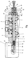
Nachstehend ist die Erfindung anhand eines in der beigefügten Zeichnung dargestellten Ausführungsbeispiels im Einzelnen erläutert, deren einzige Figur das Ausführungsbeispiel in einem abgebrochen gezeichneten Längsschnitt zeigt, wobei vom zugehörigen Schrittmotor lediglich ein abtriebsseitiges Zahnritzel nebst Zahnstange gezeigt sind.The invention with reference to an embodiment shown in the accompanying drawing is explained in detail, the single figure shows the embodiment in a broken drawn longitudinal section, wherein the associated stepper motor only a driven side pinion together with rack are shown.
Unter Bezugnahme auf die Figur ist die Erfindung am Beispiel eines 4/3-Wege-Schieberventils erläutert, das, ohne hydraulische Vorsteuerung, entsprechend dem in der genannten US-Patenschrift 7,591,448 B2 offenbarten Stand der Technik mittels eines als Ganzes mit 2 bezeichneten Schrittmotors elektrisch betätigbar ist. Ein im Ventilgehäuse 6 längsverschiebbar geführter Steuerschieber 4 ist in der Figur in seiner zentrierten, dem sicheren Zustand eines angeschlossenen Systems entsprechenden Nullstellung gezeigt, in der alle am Ventilgehäuse 6 befindlichen Fluidanschlüsse, nämlich ein Druckanschluss P, Nutzanschlüsse A und B sowie Tankanschlüsse T voneinander getrennt sind. Um zu vermeiden, dass der Steuerschieber 4 im Betrieb an seinen Stirnseiten durch Leckageströme mit Druck beaufschlagt wird, was ungewollte Stellkräfte am Steuerschieber 4 zur Folge hätte, sind die beiden Endbereiche des Steuerschiebers 4 über Dichtelemente 8 aus dem Ventilgehäuse 6 herausgeführt. Für die Betätigung durch den Schrittmotor 2 ist der Schieber 4 mit seinem in der Figur links gelegenen Endbereich 10 mit der Zahnstange 12 des Schrittmotors 2 in Verbindung, der, dem genannten Stand der Technik entsprechend, die Zahnstange 12 über ein Zahnritzel 14 translatorisch bewegt. Für die Kopplung des Endbereichs 10 mit der Zahnstange 12 weist diese am Verbindungsende einen Kugelkopf 16 auf, der in eine koaxiale Sackbohrung 18 im Endbereich 10 eingreift und gegen Austritt aus der Sackbohrung 18 durch einen Sprengring 20 gesichert ist. Für die spielfreie Anlage des Kugelkopfes 16 am Sprengring 20 befindet sich in der Sackbohrung 18 eine Druckfeder 22.With reference to the figure, the invention is illustrated by the example of a 4/3-way spool valve, which, without hydraulic pilot control, according to the state of the art disclosed in said US Pat. No. 7,591,448 B2 by means of a stepping
An seinem dem Schrittmotor 2 entgegengesetzten Endbereich ist der Steuerschieber 4 über eine zweiteilig ausgebildete Führungseinrichtung aus dem Ventilgehäuse 6 herausgeführt. Diese Führungseinrichtung weist eine die eigentliche Längsführung für den Steuerschieber 4 bildende Führungshülse 24, die sich am äußeren Ende des Ventilgehäuses 6 an das Dichtelement 8 anschließt, sowie eine an der Außenseite der Führungshülse 24 anliegende Steuerscheibe 26 auf. Die Führungshülse 24 ist in ihrem aus dem Ende des Ventilgehäuses 6 vorstehenden Teil vom Verbindungsflansch 28 einer mit dem Ende des Ventilgehäuses 6 verschraubten Gehäuse-Endkappe 30 umfasst. Die Steuerscheibe 26 weist eine zentrale Öffnung 32 auf, durch die sich eine Steuerstange 34 hindurch erstreckt, die mit einer Gewindebohrung 36 im Steuerschieber 4 verschraubt ist. Die Steuerstange 34 erstreckt sich durch den ein kreiszylindrisches Federgehäuse bildenden Innenraum 38 der Endkappe 30 hindurch und tritt mit einem vorstehenden Betätigungsabschnitt 40 über ein am Ende der Endkappe 30 befindliches Dichtelement 42 aus dieser aus.At its end region opposite to the stepping
Im Innenraum 38 der Endkappe 30 befindet sich ein Energiespeicher in Form einer Druckfeder 44, die sich mit einem Ende an der ein Widerlager bildenden Steuerscheibe 26 abstützt, die am stirnseitigen Ende des Steuerschiebers 4 anliegt. Die die Steuerstange 34 umgebende Druckfeder 44 umgibt auch die Außenseite einer von der Steuerstange 34 durchgriffenen Aufnahmehülse 46, die an ihrem vom Steuerschieber 4 entfernten Ende einen radial nach außen vorstehenden Rand 48 besitzt, der das zweite Widerlager für die Druckfeder 44 bildet. Bei dem in der Figur gezeigten Zustand, der der zentrierten Nullstellung und einem sicheren Zustand des Ventils entspricht, liegt der Endrand 48der Aufnahmehülse 46 am Ende des Innenraums 38 an der Endkappe 30 an. Gleichzeitig liegt die Steuerstange 34 mit einer Querschnittsverbreiterung 50 am inneren Rand der demgegenüber im Durchmesser verringerten Durchgangsöffnung 51 der Aufnahmehülse 46 an. Wird bei einer Steuerbewegung der Steuerschieber 4 aus der gezeigten Nullstellung in Richtung auf den Schrittmotor 2 betätigt, um den Druckanschluss P mit dem Nutzanschluss A und einen Tankanschluss T mit dem Nutzanschluss B zu verbinden, dann hebt die von der Querschnittsverbreiterung 50 der Steuerstange 34 mitgenommene Aufnahmehülse 46 von der Anlage am Ende der Endkappe 30 ab. Der Steuerschieber 4 bewegt sich also gegen die Wirkung der Druckfeder 44 in der Figur nach links.In the interior 38 of the end cap 30 is an energy storage in the form of a
Wird der Steuerschieber 4 für eine vom Schrittmotor 2 weg gerichtete Bewegung aus der gezeigten Nullstellung heraus betätigt, dann hebt die Querschnittsverbreiterung 50 vom Rand der Öffnung 51 der Aufnahmehülse 46 ab und bewegt sich innerhalb der Aufnahmehülse 46 in der Figur nach rechts, wobei diese Bewegung entgegen der Wirkung der Druckfeder 44 erfolgt, da sich das durch die Steuerscheibe 26 gebildete Widerlager mit dem Steuerschieber 4 nach rechts bewegt. Die axiale Länge der Aufnahmehülse 46 ist so bemessen, dass der Steuerschieber 4 ausreichend weit verschiebbar ist, um den Druckanschluss P mit dem Nutzanschluss B und den Nutzanschluss A mit einem Druckanschluss T zu verbinden.If the
Wie erwähnt, ist die Steuerstange 34 mit dem Betätigungsabschnitt 40 aus der Endkappe 30 herausgeführt und dadurch für eine Notbetätigung des Ventils zugänglich. Beim gezeigten Beispiel ist für eine direkte manuelle Notbetätigung ein am Ende des Betätigungsabschnitts 40 der Steuerstange 34 befestigter Notfallknopf 52 angeordnet. Die gezeigte Bauweise, bei der Steuerstange 34 und Betätigungsabschnitt 40 einteilig ausgebildet sind, ist nicht zwingend. Beispielsweise könnte der Betätigungsabschnitt 40 ein gesondertes Adapterteil sein, das mit dem übrigen Teil der Steuerstange 34 verschraubt ist. Auch könnte der Steuerschieber 4 selbst konstruktiv so ausgebildet sein, dass er aus der das Federgehäuse bildenden Endkappe 30 herausragt und selbst als Betätigungsteil für die Notbetätigung nutzbar ist. Da, wie erwähnt, durch die Abdichtung des Steuerschiebers 4 mittels der am Gehäuseende vorgesehenen Dichtelemente 8 der Innenraum 38 der Endkappe 30, anders als bei hydraulisch vorgesteuerten Systemen, nicht unter Druck steht, kann an der Herausführung der Steuerstange 34 aus der Endkappe ein einfacher Dichtring 42 vorgesehen sein, da lediglich eine Abdichtung gegen Spritzwasser oder Schmutzeintrag von außen her vorgesehen sein muss.As mentioned, the
Claims (8)
- A valve with a step motor (2) and a control slide (4) guided in a valve housing (6) so as to be longitudinally movable, which control slide selectively connects a plurality of fluid connection points (P, T, A, B) in the valve housing (6) to each other in a fluid-conducting manner or disconnects said fluid connection points from each other and can be electrically controlled by means of the step motor (2), wherein the control slide (4) can be actuated by means of an emergency device (34, 52) in the event of a malfunction or failure and wherein the free end of the control slide (4) is connected to a control rod (34) of the emergency device (34, 52), which makes possible a manual actuation when free end thereof is guided out of the valve housing (6), characterised in that the control slide (4) is movably mounted between a toothed rack (12) of the step motor (2) and the control rod (34) of the emergency device in the valve housing (6) for the valve actuation by means of the step rotor (2), that the toothed rack (12) is engaged with a toothed pinion (14) coupled to the step motor (2) and that the manual actuation is made possible preferably via an emergency button (52) arranged at the free end of the control rod (34).
- The valve according to claim 1, characterised in that the control rod (34) of the emergency device passes through an energy storage device, in particular in the form of a compression spring (44), the one free end of which is supported by a guide (24, 26) of the control slide (4) or parts (26) thereof and the other end of which rests on a mounting sleeve (46), which is also penetrated by the control rod (34).
- The valve according to claim 2, characterised in that the mounting sleeve (46) has a reduction of cross-section (51) at its free end, which reduction forms an end stop for the control rod (34) of the emergency device (34, 52), which, provided with an enlargement of cross-section (50), is guided in an end cap (30) of the valve housing (6) so as to be displaceable against the end stop.
- The valve according to claim 3, characterised in that the axial length of the mounting sleeve (46) is selected such that, when the control rod (34) reaches the end stop, the control slide (6) attains its blocking position, separating the fluid connection points (P, T, A, B) in the valve housing (6) from one another.
- The valve according to claims 3-4, characterised in that the axial length of the mounting sleeve (46) is selected such that, upon movement of the enlargement of cross-section (50) of the control rod (34) away from the step motor (2), the control slide (4) assumes a further operating position, different from the blocking position and opposed to the effect of the energy storage device (44), in which at least a part of the fluid connection points (P→B, A→T) are connected to one another.
- The valve according to claims 3-5, characterised in that, upon a movement of the control rod (34) towards the step motor (2), the mounting sleeve (46) is lifted from its further stop position at the end cap (36) by means of the enlargement of cross-section (50) bearing on the end stop against the effect of the energy storage device (44) and, subsequent to the movement of the control rod (34), the control slide (34) reaches a further operating position, which is different from the blocking position and the one operating position, in which at least a part of the fluid connection points (P→A, B→T) are connected to one another.
- The valve according to claims 2-6, characterised in that the control slide (4) passes through a guide (24, 26) which, being designed in two parts, serves with a guide part (24) for end-side longitudinal guiding of the control slide (4) in this region and forms, with a control disk (26) supported by the guide part (24), a support for supporting the one end of the energy storage device (44) of the emergency device.
- The valve according to one of the preceding claims, characterised in that it is designed as a 4/3-way sliding valve and that the valve housing (6) has for this purpose fluid connection points in the form of a pressure supply port (P), two tank ports (T) and two service ports (A, B).
Applications Claiming Priority (2)
| Application Number | Priority Date | Filing Date | Title |
|---|---|---|---|
| DE102015001883.3A DE102015001883A1 (en) | 2015-02-13 | 2015-02-13 | Valve with a longitudinally movable in a valve housing spool |
| PCT/EP2016/000097 WO2016128106A1 (en) | 2015-02-13 | 2016-01-20 | Valve having a control slide guided in a valve housing so as to be longitudinally movable |
Publications (2)
| Publication Number | Publication Date |
|---|---|
| EP3256743A1 EP3256743A1 (en) | 2017-12-20 |
| EP3256743B1 true EP3256743B1 (en) | 2019-07-31 |
Family
ID=55221383
Family Applications (1)
| Application Number | Title | Priority Date | Filing Date |
|---|---|---|---|
| EP16701252.5A Active EP3256743B1 (en) | 2015-02-13 | 2016-01-20 | Valve having a control slide guided in a valve housing so as to be longitudinally movable |
Country Status (4)
| Country | Link |
|---|---|
| US (1) | US10408363B2 (en) |
| EP (1) | EP3256743B1 (en) |
| DE (1) | DE102015001883A1 (en) |
| WO (1) | WO2016128106A1 (en) |
Families Citing this family (3)
| Publication number | Priority date | Publication date | Assignee | Title |
|---|---|---|---|---|
| EP3483454A1 (en) * | 2017-11-10 | 2019-05-15 | Société Industrielle de Sonceboz S.A. | Hydraulic control |
| GB2587945B (en) * | 2018-05-17 | 2023-04-12 | Kawasaki Heavy Ind Ltd | Spool valve |
| CN113324088B (en) * | 2021-06-16 | 2022-12-13 | 徐州阿马凯液压技术有限公司 | Hydraulic control clutch manual control structure of hydraulic valve |
Family Cites Families (12)
| Publication number | Priority date | Publication date | Assignee | Title |
|---|---|---|---|---|
| GB1590581A (en) * | 1976-10-14 | 1981-06-03 | Hawker Siddeley Dynamics Eng | Electro-hydraulic systems |
| GB2085129B (en) * | 1980-10-09 | 1985-04-03 | Kontak Mfg Co Ltd | Valve actuator |
| US4437388A (en) * | 1981-08-20 | 1984-03-20 | Caterpillar Tractor Company | Dual input pressure compensated fluid control valve |
| DE3704312A1 (en) * | 1987-02-12 | 1988-08-25 | Hans Schoen | ELECTROHYDRAULIC CONTROL ARRANGEMENT |
| DE4237852A1 (en) * | 1992-11-10 | 1994-05-11 | Fichtel & Sachs Ag | Hydraulic positioning cylinder for friction clutch of motor vehicle - has motor-stepped control valve integrated into piston for selective connection of working space to pressure source or sink |
| US7591448B2 (en) | 2006-11-27 | 2009-09-22 | Societe Industrielle De Sonceboz S.A. | Hydraulic control valve system |
| DE102007031429A1 (en) * | 2007-07-05 | 2009-01-08 | Thomas Magnete Gmbh | Drive device for control slide of four by three way valve, has energy storage storing energy for actuation of control slide, and movement of motor caused in position detected as safe condition of valve during breakdown or error recovery |
| US8939173B2 (en) * | 2010-07-14 | 2015-01-27 | Mac Valves, Inc. | Stepper motor operated balanced flow control valve |
| DE102011005868A1 (en) | 2011-03-21 | 2012-09-27 | Deere & Company | Valve control device for a vehicle |
| DE202011103482U1 (en) * | 2011-04-04 | 2011-11-09 | Ak Regeltechnik Gmbh | Servo module for valve control |
| DE102013021317A1 (en) * | 2013-12-16 | 2015-06-18 | Hydac Filtertechnik Gmbh | Hydraulic valve device |
| EP3587830B1 (en) * | 2014-05-01 | 2022-04-27 | Danfoss Power Solutions II Technology A/S | Spool valve connection arrangement for manual override assembly |
-
2015
- 2015-02-13 DE DE102015001883.3A patent/DE102015001883A1/en not_active Withdrawn
-
2016
- 2016-01-20 WO PCT/EP2016/000097 patent/WO2016128106A1/en active Application Filing
- 2016-01-20 US US15/542,449 patent/US10408363B2/en active Active
- 2016-01-20 EP EP16701252.5A patent/EP3256743B1/en active Active
Non-Patent Citations (1)
| Title |
|---|
| None * |
Also Published As
| Publication number | Publication date |
|---|---|
| EP3256743A1 (en) | 2017-12-20 |
| US20180274691A1 (en) | 2018-09-27 |
| WO2016128106A1 (en) | 2016-08-18 |
| US10408363B2 (en) | 2019-09-10 |
| DE102015001883A1 (en) | 2016-09-01 |
Similar Documents
| Publication | Publication Date | Title |
|---|---|---|
| DE2703349C3 (en) | Valve device for controlling a reciprocating piston for upward travel in an elevator car | |
| EP3256742B1 (en) | Pressure-limiting valve | |
| EP3256743B1 (en) | Valve having a control slide guided in a valve housing so as to be longitudinally movable | |
| WO2017108183A1 (en) | Valve, in particular a 4/2-way slide valve | |
| DE102014212570A1 (en) | Blocking device for a closing sequence control device of a two-leaf revolving door system | |
| EP1985854B1 (en) | Pump system | |
| DE102011119784A1 (en) | Fluid-operated gripping device has safety device to divide gripping movement of movable grippers based on relative position of grippers into high power stage at end of gripping movement and safety phase at upstream of high power stage | |
| EP0928388A1 (en) | Turbine valve actuator | |
| EP3608286B1 (en) | Industrial truck with hydraulic lifting system and electronic protection of the lifting system against malfunction | |
| DE10219718B4 (en) | Hydraulic valve arrangement | |
| DE102008061238B4 (en) | Device for a hydraulic drive for an electrical switchgear | |
| DE102013007604A1 (en) | Linear actuator with unlocking device and landing gear for an aircraft | |
| DE102022111767B3 (en) | Swivel joint for a robot | |
| DE102004044962B4 (en) | Pressure-medium actuated adjusting device | |
| DE102013218549A1 (en) | Electrohydraulic actuator | |
| EP2008898B1 (en) | Electrically controllable assembly with a hydraulic connection | |
| EP3477121B1 (en) | Pressure limiting unit for a pressure booster and a pressure booster for driving of hydraulics tools | |
| EP1523626B1 (en) | Hydraulic cylinder | |
| DE10229276A1 (en) | Device for overload protection in a press | |
| DE2106195C2 (en) | Manifold assembly for pressurized fluid with two manifolds | |
| DE102005052692B3 (en) | Electrohydraulic monitoring device for dual effect hydraulic cylinder, has regulating sleeve, which has piston surface on radially outer side for delimitation of sensor chamber | |
| DE19515884A1 (en) | Device for securing an electrohydraulic drive unit | |
| EP2550461A1 (en) | Device for locking an axially movable component of a hydraulic system | |
| EP2318742A1 (en) | Hydraulic valve device | |
| EP1084924A2 (en) | Pressure limiting and protection valve for motor vehicle compressed air brake systems |
Legal Events
| Date | Code | Title | Description |
|---|---|---|---|
| STAA | Information on the status of an ep patent application or granted ep patent |
Free format text: STATUS: THE INTERNATIONAL PUBLICATION HAS BEEN MADE |
|
| PUAI | Public reference made under article 153(3) epc to a published international application that has entered the european phase |
Free format text: ORIGINAL CODE: 0009012 |
|
| STAA | Information on the status of an ep patent application or granted ep patent |
Free format text: STATUS: REQUEST FOR EXAMINATION WAS MADE |
|
| 17P | Request for examination filed |
Effective date: 20170503 |
|
| AK | Designated contracting states |
Kind code of ref document: A1 Designated state(s): AL AT BE BG CH CY CZ DE DK EE ES FI FR GB GR HR HU IE IS IT LI LT LU LV MC MK MT NL NO PL PT RO RS SE SI SK SM TR |
|
| AX | Request for extension of the european patent |
Extension state: BA ME |
|
| RAP1 | Party data changed (applicant data changed or rights of an application transferred) |
Owner name: HYDAC SYSTEM GMBH |
|
| DAV | Request for validation of the european patent (deleted) | ||
| DAX | Request for extension of the european patent (deleted) | ||
| RAP1 | Party data changed (applicant data changed or rights of an application transferred) |
Owner name: HYDAC SYSTEMS & SERVICES GMBH |
|
| GRAP | Despatch of communication of intention to grant a patent |
Free format text: ORIGINAL CODE: EPIDOSNIGR1 |
|
| STAA | Information on the status of an ep patent application or granted ep patent |
Free format text: STATUS: GRANT OF PATENT IS INTENDED |
|
| INTG | Intention to grant announced |
Effective date: 20190416 |
|
| GRAS | Grant fee paid |
Free format text: ORIGINAL CODE: EPIDOSNIGR3 |
|
| GRAA | (expected) grant |
Free format text: ORIGINAL CODE: 0009210 |
|
| STAA | Information on the status of an ep patent application or granted ep patent |
Free format text: STATUS: THE PATENT HAS BEEN GRANTED |
|
| AK | Designated contracting states |
Kind code of ref document: B1 Designated state(s): AL AT BE BG CH CY CZ DE DK EE ES FI FR GB GR HR HU IE IS IT LI LT LU LV MC MK MT NL NO PL PT RO RS SE SI SK SM TR |
|
| REG | Reference to a national code |
Ref country code: CH Ref legal event code: EP Ref country code: GB Ref legal event code: FG4D Free format text: NOT ENGLISH |
|
| REG | Reference to a national code |
Ref country code: AT Ref legal event code: REF Ref document number: 1161201 Country of ref document: AT Kind code of ref document: T Effective date: 20190815 |
|
| REG | Reference to a national code |
Ref country code: IE Ref legal event code: FG4D Free format text: LANGUAGE OF EP DOCUMENT: GERMAN |
|
| REG | Reference to a national code |
Ref country code: DE Ref legal event code: R096 Ref document number: 502016005792 Country of ref document: DE |
|
| REG | Reference to a national code |
Ref country code: NL Ref legal event code: MP Effective date: 20190731 |
|
| REG | Reference to a national code |
Ref country code: LT Ref legal event code: MG4D |
|
| PG25 | Lapsed in a contracting state [announced via postgrant information from national office to epo] |
Ref country code: HR Free format text: LAPSE BECAUSE OF FAILURE TO SUBMIT A TRANSLATION OF THE DESCRIPTION OR TO PAY THE FEE WITHIN THE PRESCRIBED TIME-LIMIT Effective date: 20190731 Ref country code: BG Free format text: LAPSE BECAUSE OF FAILURE TO SUBMIT A TRANSLATION OF THE DESCRIPTION OR TO PAY THE FEE WITHIN THE PRESCRIBED TIME-LIMIT Effective date: 20191031 Ref country code: NL Free format text: LAPSE BECAUSE OF FAILURE TO SUBMIT A TRANSLATION OF THE DESCRIPTION OR TO PAY THE FEE WITHIN THE PRESCRIBED TIME-LIMIT Effective date: 20190731 Ref country code: LT Free format text: LAPSE BECAUSE OF FAILURE TO SUBMIT A TRANSLATION OF THE DESCRIPTION OR TO PAY THE FEE WITHIN THE PRESCRIBED TIME-LIMIT Effective date: 20190731 Ref country code: PT Free format text: LAPSE BECAUSE OF FAILURE TO SUBMIT A TRANSLATION OF THE DESCRIPTION OR TO PAY THE FEE WITHIN THE PRESCRIBED TIME-LIMIT Effective date: 20191202 Ref country code: SE Free format text: LAPSE BECAUSE OF FAILURE TO SUBMIT A TRANSLATION OF THE DESCRIPTION OR TO PAY THE FEE WITHIN THE PRESCRIBED TIME-LIMIT Effective date: 20190731 Ref country code: FI Free format text: LAPSE BECAUSE OF FAILURE TO SUBMIT A TRANSLATION OF THE DESCRIPTION OR TO PAY THE FEE WITHIN THE PRESCRIBED TIME-LIMIT Effective date: 20190731 Ref country code: NO Free format text: LAPSE BECAUSE OF FAILURE TO SUBMIT A TRANSLATION OF THE DESCRIPTION OR TO PAY THE FEE WITHIN THE PRESCRIBED TIME-LIMIT Effective date: 20191031 |
|
| PG25 | Lapsed in a contracting state [announced via postgrant information from national office to epo] |
Ref country code: RS Free format text: LAPSE BECAUSE OF FAILURE TO SUBMIT A TRANSLATION OF THE DESCRIPTION OR TO PAY THE FEE WITHIN THE PRESCRIBED TIME-LIMIT Effective date: 20190731 Ref country code: ES Free format text: LAPSE BECAUSE OF FAILURE TO SUBMIT A TRANSLATION OF THE DESCRIPTION OR TO PAY THE FEE WITHIN THE PRESCRIBED TIME-LIMIT Effective date: 20190731 Ref country code: GR Free format text: LAPSE BECAUSE OF FAILURE TO SUBMIT A TRANSLATION OF THE DESCRIPTION OR TO PAY THE FEE WITHIN THE PRESCRIBED TIME-LIMIT Effective date: 20191101 Ref country code: LV Free format text: LAPSE BECAUSE OF FAILURE TO SUBMIT A TRANSLATION OF THE DESCRIPTION OR TO PAY THE FEE WITHIN THE PRESCRIBED TIME-LIMIT Effective date: 20190731 Ref country code: IS Free format text: LAPSE BECAUSE OF FAILURE TO SUBMIT A TRANSLATION OF THE DESCRIPTION OR TO PAY THE FEE WITHIN THE PRESCRIBED TIME-LIMIT Effective date: 20191130 Ref country code: AL Free format text: LAPSE BECAUSE OF FAILURE TO SUBMIT A TRANSLATION OF THE DESCRIPTION OR TO PAY THE FEE WITHIN THE PRESCRIBED TIME-LIMIT Effective date: 20190731 |
|
| PG25 | Lapsed in a contracting state [announced via postgrant information from national office to epo] |
Ref country code: TR Free format text: LAPSE BECAUSE OF FAILURE TO SUBMIT A TRANSLATION OF THE DESCRIPTION OR TO PAY THE FEE WITHIN THE PRESCRIBED TIME-LIMIT Effective date: 20190731 |
|
| PG25 | Lapsed in a contracting state [announced via postgrant information from national office to epo] |
Ref country code: DK Free format text: LAPSE BECAUSE OF FAILURE TO SUBMIT A TRANSLATION OF THE DESCRIPTION OR TO PAY THE FEE WITHIN THE PRESCRIBED TIME-LIMIT Effective date: 20190731 Ref country code: PL Free format text: LAPSE BECAUSE OF FAILURE TO SUBMIT A TRANSLATION OF THE DESCRIPTION OR TO PAY THE FEE WITHIN THE PRESCRIBED TIME-LIMIT Effective date: 20190731 Ref country code: EE Free format text: LAPSE BECAUSE OF FAILURE TO SUBMIT A TRANSLATION OF THE DESCRIPTION OR TO PAY THE FEE WITHIN THE PRESCRIBED TIME-LIMIT Effective date: 20190731 Ref country code: RO Free format text: LAPSE BECAUSE OF FAILURE TO SUBMIT A TRANSLATION OF THE DESCRIPTION OR TO PAY THE FEE WITHIN THE PRESCRIBED TIME-LIMIT Effective date: 20190731 |
|
| PG25 | Lapsed in a contracting state [announced via postgrant information from national office to epo] |
Ref country code: SM Free format text: LAPSE BECAUSE OF FAILURE TO SUBMIT A TRANSLATION OF THE DESCRIPTION OR TO PAY THE FEE WITHIN THE PRESCRIBED TIME-LIMIT Effective date: 20190731 Ref country code: SK Free format text: LAPSE BECAUSE OF FAILURE TO SUBMIT A TRANSLATION OF THE DESCRIPTION OR TO PAY THE FEE WITHIN THE PRESCRIBED TIME-LIMIT Effective date: 20190731 Ref country code: IS Free format text: LAPSE BECAUSE OF FAILURE TO SUBMIT A TRANSLATION OF THE DESCRIPTION OR TO PAY THE FEE WITHIN THE PRESCRIBED TIME-LIMIT Effective date: 20200224 Ref country code: CZ Free format text: LAPSE BECAUSE OF FAILURE TO SUBMIT A TRANSLATION OF THE DESCRIPTION OR TO PAY THE FEE WITHIN THE PRESCRIBED TIME-LIMIT Effective date: 20190731 |
|
| REG | Reference to a national code |
Ref country code: DE Ref legal event code: R097 Ref document number: 502016005792 Country of ref document: DE |
|
| PLBE | No opposition filed within time limit |
Free format text: ORIGINAL CODE: 0009261 |
|
| STAA | Information on the status of an ep patent application or granted ep patent |
Free format text: STATUS: NO OPPOSITION FILED WITHIN TIME LIMIT |
|
| PG2D | Information on lapse in contracting state deleted |
Ref country code: IS |
|
| PG25 | Lapsed in a contracting state [announced via postgrant information from national office to epo] |
Ref country code: IS Free format text: LAPSE BECAUSE OF FAILURE TO SUBMIT A TRANSLATION OF THE DESCRIPTION OR TO PAY THE FEE WITHIN THE PRESCRIBED TIME-LIMIT Effective date: 20191030 |
|
| 26N | No opposition filed |
Effective date: 20200603 |
|
| PG25 | Lapsed in a contracting state [announced via postgrant information from national office to epo] |
Ref country code: SI Free format text: LAPSE BECAUSE OF FAILURE TO SUBMIT A TRANSLATION OF THE DESCRIPTION OR TO PAY THE FEE WITHIN THE PRESCRIBED TIME-LIMIT Effective date: 20190731 Ref country code: MC Free format text: LAPSE BECAUSE OF FAILURE TO SUBMIT A TRANSLATION OF THE DESCRIPTION OR TO PAY THE FEE WITHIN THE PRESCRIBED TIME-LIMIT Effective date: 20190731 |
|
| REG | Reference to a national code |
Ref country code: CH Ref legal event code: PL |
|
| GBPC | Gb: european patent ceased through non-payment of renewal fee |
Effective date: 20200120 |
|
| REG | Reference to a national code |
Ref country code: BE Ref legal event code: MM Effective date: 20200131 |
|
| PG25 | Lapsed in a contracting state [announced via postgrant information from national office to epo] |
Ref country code: LU Free format text: LAPSE BECAUSE OF NON-PAYMENT OF DUE FEES Effective date: 20200120 Ref country code: GB Free format text: LAPSE BECAUSE OF NON-PAYMENT OF DUE FEES Effective date: 20200120 Ref country code: FR Free format text: LAPSE BECAUSE OF NON-PAYMENT OF DUE FEES Effective date: 20200131 |
|
| PG25 | Lapsed in a contracting state [announced via postgrant information from national office to epo] |
Ref country code: LI Free format text: LAPSE BECAUSE OF NON-PAYMENT OF DUE FEES Effective date: 20200131 Ref country code: CH Free format text: LAPSE BECAUSE OF NON-PAYMENT OF DUE FEES Effective date: 20200131 Ref country code: BE Free format text: LAPSE BECAUSE OF NON-PAYMENT OF DUE FEES Effective date: 20200131 |
|
| PG25 | Lapsed in a contracting state [announced via postgrant information from national office to epo] |
Ref country code: IE Free format text: LAPSE BECAUSE OF NON-PAYMENT OF DUE FEES Effective date: 20200120 |
|
| REG | Reference to a national code |
Ref country code: AT Ref legal event code: MM01 Ref document number: 1161201 Country of ref document: AT Kind code of ref document: T Effective date: 20210120 |
|
| PG25 | Lapsed in a contracting state [announced via postgrant information from national office to epo] |
Ref country code: AT Free format text: LAPSE BECAUSE OF NON-PAYMENT OF DUE FEES Effective date: 20210120 |
|
| PG25 | Lapsed in a contracting state [announced via postgrant information from national office to epo] |
Ref country code: MT Free format text: LAPSE BECAUSE OF FAILURE TO SUBMIT A TRANSLATION OF THE DESCRIPTION OR TO PAY THE FEE WITHIN THE PRESCRIBED TIME-LIMIT Effective date: 20190731 Ref country code: CY Free format text: LAPSE BECAUSE OF FAILURE TO SUBMIT A TRANSLATION OF THE DESCRIPTION OR TO PAY THE FEE WITHIN THE PRESCRIBED TIME-LIMIT Effective date: 20190731 |
|
| PG25 | Lapsed in a contracting state [announced via postgrant information from national office to epo] |
Ref country code: MK Free format text: LAPSE BECAUSE OF FAILURE TO SUBMIT A TRANSLATION OF THE DESCRIPTION OR TO PAY THE FEE WITHIN THE PRESCRIBED TIME-LIMIT Effective date: 20190731 |
|
| PGFP | Annual fee paid to national office [announced via postgrant information from national office to epo] |
Ref country code: IT Payment date: 20230111 Year of fee payment: 8 Ref country code: DE Payment date: 20230131 Year of fee payment: 8 |