EP3256717B1 - Hydroelectric/hydrokinetic turbine and methods for making and using same - Google Patents
Hydroelectric/hydrokinetic turbine and methods for making and using same Download PDFInfo
- Publication number
- EP3256717B1 EP3256717B1 EP16721272.9A EP16721272A EP3256717B1 EP 3256717 B1 EP3256717 B1 EP 3256717B1 EP 16721272 A EP16721272 A EP 16721272A EP 3256717 B1 EP3256717 B1 EP 3256717B1
- Authority
- EP
- European Patent Office
- Prior art keywords
- turbine
- accelerator shroud
- hydrofoil
- water
- rotor
- Prior art date
- Legal status (The legal status is an assumption and is not a legal conclusion. Google has not performed a legal analysis and makes no representation as to the accuracy of the status listed.)
- Active
Links
Images


Classifications
-
- F—MECHANICAL ENGINEERING; LIGHTING; HEATING; WEAPONS; BLASTING
- F03—MACHINES OR ENGINES FOR LIQUIDS; WIND, SPRING, OR WEIGHT MOTORS; PRODUCING MECHANICAL POWER OR A REACTIVE PROPULSIVE THRUST, NOT OTHERWISE PROVIDED FOR
- F03B—MACHINES OR ENGINES FOR LIQUIDS
- F03B3/00—Machines or engines of reaction type; Parts or details peculiar thereto
- F03B3/16—Stators
- F03B3/18—Stator blades; Guide conduits or vanes, e.g. adjustable
-
- F—MECHANICAL ENGINEERING; LIGHTING; HEATING; WEAPONS; BLASTING
- F03—MACHINES OR ENGINES FOR LIQUIDS; WIND, SPRING, OR WEIGHT MOTORS; PRODUCING MECHANICAL POWER OR A REACTIVE PROPULSIVE THRUST, NOT OTHERWISE PROVIDED FOR
- F03B—MACHINES OR ENGINES FOR LIQUIDS
- F03B11/00—Parts or details not provided for in, or of interest apart from, the preceding groups, e.g. wear-protection couplings, between turbine and generator
- F03B11/02—Casings
-
- F—MECHANICAL ENGINEERING; LIGHTING; HEATING; WEAPONS; BLASTING
- F03—MACHINES OR ENGINES FOR LIQUIDS; WIND, SPRING, OR WEIGHT MOTORS; PRODUCING MECHANICAL POWER OR A REACTIVE PROPULSIVE THRUST, NOT OTHERWISE PROVIDED FOR
- F03B—MACHINES OR ENGINES FOR LIQUIDS
- F03B17/00—Other machines or engines
- F03B17/06—Other machines or engines using liquid flow with predominantly kinetic energy conversion, e.g. of swinging-flap type, "run-of-river", "ultra-low head"
- F03B17/061—Other machines or engines using liquid flow with predominantly kinetic energy conversion, e.g. of swinging-flap type, "run-of-river", "ultra-low head" with rotation axis substantially in flow direction
-
- F—MECHANICAL ENGINEERING; LIGHTING; HEATING; WEAPONS; BLASTING
- F03—MACHINES OR ENGINES FOR LIQUIDS; WIND, SPRING, OR WEIGHT MOTORS; PRODUCING MECHANICAL POWER OR A REACTIVE PROPULSIVE THRUST, NOT OTHERWISE PROVIDED FOR
- F03B—MACHINES OR ENGINES FOR LIQUIDS
- F03B3/00—Machines or engines of reaction type; Parts or details peculiar thereto
- F03B3/04—Machines or engines of reaction type; Parts or details peculiar thereto with substantially axial flow throughout rotors, e.g. propeller turbines
-
- F—MECHANICAL ENGINEERING; LIGHTING; HEATING; WEAPONS; BLASTING
- F03—MACHINES OR ENGINES FOR LIQUIDS; WIND, SPRING, OR WEIGHT MOTORS; PRODUCING MECHANICAL POWER OR A REACTIVE PROPULSIVE THRUST, NOT OTHERWISE PROVIDED FOR
- F03B—MACHINES OR ENGINES FOR LIQUIDS
- F03B3/00—Machines or engines of reaction type; Parts or details peculiar thereto
- F03B3/12—Blades; Blade-carrying rotors
- F03B3/121—Blades, their form or construction
-
- F—MECHANICAL ENGINEERING; LIGHTING; HEATING; WEAPONS; BLASTING
- F03—MACHINES OR ENGINES FOR LIQUIDS; WIND, SPRING, OR WEIGHT MOTORS; PRODUCING MECHANICAL POWER OR A REACTIVE PROPULSIVE THRUST, NOT OTHERWISE PROVIDED FOR
- F03B—MACHINES OR ENGINES FOR LIQUIDS
- F03B3/00—Machines or engines of reaction type; Parts or details peculiar thereto
- F03B3/12—Blades; Blade-carrying rotors
- F03B3/126—Rotors for essentially axial flow, e.g. for propeller turbines
-
- H—ELECTRICITY
- H02—GENERATION; CONVERSION OR DISTRIBUTION OF ELECTRIC POWER
- H02K—DYNAMO-ELECTRIC MACHINES
- H02K7/00—Arrangements for handling mechanical energy structurally associated with dynamo-electric machines, e.g. structural association with mechanical driving motors or auxiliary dynamo-electric machines
- H02K7/18—Structural association of electric generators with mechanical driving motors, e.g. with turbines
-
- F—MECHANICAL ENGINEERING; LIGHTING; HEATING; WEAPONS; BLASTING
- F05—INDEXING SCHEMES RELATING TO ENGINES OR PUMPS IN VARIOUS SUBCLASSES OF CLASSES F01-F04
- F05B—INDEXING SCHEME RELATING TO WIND, SPRING, WEIGHT, INERTIA OR LIKE MOTORS, TO MACHINES OR ENGINES FOR LIQUIDS COVERED BY SUBCLASSES F03B, F03D AND F03G
- F05B2220/00—Application
- F05B2220/70—Application in combination with
- F05B2220/706—Application in combination with an electrical generator
- F05B2220/7068—Application in combination with an electrical generator equipped with permanent magnets
-
- F—MECHANICAL ENGINEERING; LIGHTING; HEATING; WEAPONS; BLASTING
- F05—INDEXING SCHEMES RELATING TO ENGINES OR PUMPS IN VARIOUS SUBCLASSES OF CLASSES F01-F04
- F05B—INDEXING SCHEME RELATING TO WIND, SPRING, WEIGHT, INERTIA OR LIKE MOTORS, TO MACHINES OR ENGINES FOR LIQUIDS COVERED BY SUBCLASSES F03B, F03D AND F03G
- F05B2230/00—Manufacture
- F05B2230/60—Assembly methods
- F05B2230/61—Assembly methods using auxiliary equipment for lifting or holding
- F05B2230/6102—Assembly methods using auxiliary equipment for lifting or holding carried on a floating platform
-
- F—MECHANICAL ENGINEERING; LIGHTING; HEATING; WEAPONS; BLASTING
- F05—INDEXING SCHEMES RELATING TO ENGINES OR PUMPS IN VARIOUS SUBCLASSES OF CLASSES F01-F04
- F05B—INDEXING SCHEME RELATING TO WIND, SPRING, WEIGHT, INERTIA OR LIKE MOTORS, TO MACHINES OR ENGINES FOR LIQUIDS COVERED BY SUBCLASSES F03B, F03D AND F03G
- F05B2230/00—Manufacture
- F05B2230/80—Repairing, retrofitting or upgrading methods
-
- F—MECHANICAL ENGINEERING; LIGHTING; HEATING; WEAPONS; BLASTING
- F05—INDEXING SCHEMES RELATING TO ENGINES OR PUMPS IN VARIOUS SUBCLASSES OF CLASSES F01-F04
- F05B—INDEXING SCHEME RELATING TO WIND, SPRING, WEIGHT, INERTIA OR LIKE MOTORS, TO MACHINES OR ENGINES FOR LIQUIDS COVERED BY SUBCLASSES F03B, F03D AND F03G
- F05B2240/00—Components
- F05B2240/10—Stators
- F05B2240/12—Fluid guiding means, e.g. vanes
- F05B2240/124—Cascades, i.e. assemblies of similar profiles acting in parallel
-
- F—MECHANICAL ENGINEERING; LIGHTING; HEATING; WEAPONS; BLASTING
- F05—INDEXING SCHEMES RELATING TO ENGINES OR PUMPS IN VARIOUS SUBCLASSES OF CLASSES F01-F04
- F05B—INDEXING SCHEME RELATING TO WIND, SPRING, WEIGHT, INERTIA OR LIKE MOTORS, TO MACHINES OR ENGINES FOR LIQUIDS COVERED BY SUBCLASSES F03B, F03D AND F03G
- F05B2240/00—Components
- F05B2240/10—Stators
- F05B2240/13—Stators to collect or cause flow towards or away from turbines
-
- F—MECHANICAL ENGINEERING; LIGHTING; HEATING; WEAPONS; BLASTING
- F05—INDEXING SCHEMES RELATING TO ENGINES OR PUMPS IN VARIOUS SUBCLASSES OF CLASSES F01-F04
- F05B—INDEXING SCHEME RELATING TO WIND, SPRING, WEIGHT, INERTIA OR LIKE MOTORS, TO MACHINES OR ENGINES FOR LIQUIDS COVERED BY SUBCLASSES F03B, F03D AND F03G
- F05B2240/00—Components
- F05B2240/20—Rotors
- F05B2240/33—Shrouds which are part of or which are rotating with the rotor
-
- F—MECHANICAL ENGINEERING; LIGHTING; HEATING; WEAPONS; BLASTING
- F05—INDEXING SCHEMES RELATING TO ENGINES OR PUMPS IN VARIOUS SUBCLASSES OF CLASSES F01-F04
- F05B—INDEXING SCHEME RELATING TO WIND, SPRING, WEIGHT, INERTIA OR LIKE MOTORS, TO MACHINES OR ENGINES FOR LIQUIDS COVERED BY SUBCLASSES F03B, F03D AND F03G
- F05B2240/00—Components
- F05B2240/90—Mounting on supporting structures or systems
- F05B2240/91—Mounting on supporting structures or systems on a stationary structure
- F05B2240/911—Mounting on supporting structures or systems on a stationary structure already existing for a prior purpose
-
- F—MECHANICAL ENGINEERING; LIGHTING; HEATING; WEAPONS; BLASTING
- F05—INDEXING SCHEMES RELATING TO ENGINES OR PUMPS IN VARIOUS SUBCLASSES OF CLASSES F01-F04
- F05B—INDEXING SCHEME RELATING TO WIND, SPRING, WEIGHT, INERTIA OR LIKE MOTORS, TO MACHINES OR ENGINES FOR LIQUIDS COVERED BY SUBCLASSES F03B, F03D AND F03G
- F05B2240/00—Components
- F05B2240/90—Mounting on supporting structures or systems
- F05B2240/93—Mounting on supporting structures or systems on a structure floating on a liquid surface
-
- F—MECHANICAL ENGINEERING; LIGHTING; HEATING; WEAPONS; BLASTING
- F05—INDEXING SCHEMES RELATING TO ENGINES OR PUMPS IN VARIOUS SUBCLASSES OF CLASSES F01-F04
- F05B—INDEXING SCHEME RELATING TO WIND, SPRING, WEIGHT, INERTIA OR LIKE MOTORS, TO MACHINES OR ENGINES FOR LIQUIDS COVERED BY SUBCLASSES F03B, F03D AND F03G
- F05B2240/00—Components
- F05B2240/90—Mounting on supporting structures or systems
- F05B2240/97—Mounting on supporting structures or systems on a submerged structure
-
- F—MECHANICAL ENGINEERING; LIGHTING; HEATING; WEAPONS; BLASTING
- F05—INDEXING SCHEMES RELATING TO ENGINES OR PUMPS IN VARIOUS SUBCLASSES OF CLASSES F01-F04
- F05B—INDEXING SCHEME RELATING TO WIND, SPRING, WEIGHT, INERTIA OR LIKE MOTORS, TO MACHINES OR ENGINES FOR LIQUIDS COVERED BY SUBCLASSES F03B, F03D AND F03G
- F05B2250/00—Geometry
- F05B2250/20—Geometry three-dimensional
- F05B2250/23—Geometry three-dimensional prismatic
- F05B2250/232—Geometry three-dimensional prismatic conical
-
- F—MECHANICAL ENGINEERING; LIGHTING; HEATING; WEAPONS; BLASTING
- F05—INDEXING SCHEMES RELATING TO ENGINES OR PUMPS IN VARIOUS SUBCLASSES OF CLASSES F01-F04
- F05B—INDEXING SCHEME RELATING TO WIND, SPRING, WEIGHT, INERTIA OR LIKE MOTORS, TO MACHINES OR ENGINES FOR LIQUIDS COVERED BY SUBCLASSES F03B, F03D AND F03G
- F05B2250/00—Geometry
- F05B2250/70—Shape
- F05B2250/73—Shape asymmetric
-
- F—MECHANICAL ENGINEERING; LIGHTING; HEATING; WEAPONS; BLASTING
- F05—INDEXING SCHEMES RELATING TO ENGINES OR PUMPS IN VARIOUS SUBCLASSES OF CLASSES F01-F04
- F05B—INDEXING SCHEME RELATING TO WIND, SPRING, WEIGHT, INERTIA OR LIKE MOTORS, TO MACHINES OR ENGINES FOR LIQUIDS COVERED BY SUBCLASSES F03B, F03D AND F03G
- F05B2260/00—Function
- F05B2260/84—Modelling or simulation
-
- Y—GENERAL TAGGING OF NEW TECHNOLOGICAL DEVELOPMENTS; GENERAL TAGGING OF CROSS-SECTIONAL TECHNOLOGIES SPANNING OVER SEVERAL SECTIONS OF THE IPC; TECHNICAL SUBJECTS COVERED BY FORMER USPC CROSS-REFERENCE ART COLLECTIONS [XRACs] AND DIGESTS
- Y02—TECHNOLOGIES OR APPLICATIONS FOR MITIGATION OR ADAPTATION AGAINST CLIMATE CHANGE
- Y02E—REDUCTION OF GREENHOUSE GAS [GHG] EMISSIONS, RELATED TO ENERGY GENERATION, TRANSMISSION OR DISTRIBUTION
- Y02E10/00—Energy generation through renewable energy sources
- Y02E10/20—Hydro energy
-
- Y—GENERAL TAGGING OF NEW TECHNOLOGICAL DEVELOPMENTS; GENERAL TAGGING OF CROSS-SECTIONAL TECHNOLOGIES SPANNING OVER SEVERAL SECTIONS OF THE IPC; TECHNICAL SUBJECTS COVERED BY FORMER USPC CROSS-REFERENCE ART COLLECTIONS [XRACs] AND DIGESTS
- Y02—TECHNOLOGIES OR APPLICATIONS FOR MITIGATION OR ADAPTATION AGAINST CLIMATE CHANGE
- Y02E—REDUCTION OF GREENHOUSE GAS [GHG] EMISSIONS, RELATED TO ENERGY GENERATION, TRANSMISSION OR DISTRIBUTION
- Y02E10/00—Energy generation through renewable energy sources
- Y02E10/30—Energy from the sea, e.g. using wave energy or salinity gradient
-
- Y—GENERAL TAGGING OF NEW TECHNOLOGICAL DEVELOPMENTS; GENERAL TAGGING OF CROSS-SECTIONAL TECHNOLOGIES SPANNING OVER SEVERAL SECTIONS OF THE IPC; TECHNICAL SUBJECTS COVERED BY FORMER USPC CROSS-REFERENCE ART COLLECTIONS [XRACs] AND DIGESTS
- Y02—TECHNOLOGIES OR APPLICATIONS FOR MITIGATION OR ADAPTATION AGAINST CLIMATE CHANGE
- Y02P—CLIMATE CHANGE MITIGATION TECHNOLOGIES IN THE PRODUCTION OR PROCESSING OF GOODS
- Y02P70/00—Climate change mitigation technologies in the production process for final industrial or consumer products
- Y02P70/50—Manufacturing or production processes characterised by the final manufactured product
Definitions
- the present invention relates to hydrokinetic turbines designed for the purpose of generating electricity, and to methods for designing and using such turbines. It further relates to certain elements employed in hydrokinetic turbines.
- the turbines according to the invention are intended to be placed underwater, in a fixed, floating, anchored or towed configuration, in any location where the effective water current preferably flows with a minimum speed of about 0.25m/s.
- the water flow or current may be of any type or source, although typically it is comprised of one or more of the following types of water flow or current:
- Hydrofoils (as well as airfoils, also part of fluid dynamics) are used for a large variety of purposes, including most designs in aeronautics, in motor vehicles, in watercraft, and in isolated elements employed in hydrokinetic turbines.
- Hydrokinetic turbines can be divided up into different categories or types.
- a turbine can either be bi-directional or unidirectional.
- the turbine in defined such that it can be operated by a current that flows in both axial directions through the turbine, e.g., to be actuated to generate power both by an incoming tidal flow as well as by a receding tidal flow.
- a unidirectional turbine is driven only by the flow of water in a single axial direction. From a hydrodynamic standpoint, the design criteria to produce a bi-directional turbine are significantly more limited than in the case of a unidirectional turbine, i.e., all design criteria that would produce an adverse effect upon reversal of fluid flow direction.
- hydrodynamic turbine designs in which there is provided an open center hub, for environmental reasons, i.e., to provide a safe passageway for sea creatures. See, e.g., the following documents for examples: US 6,957,947 , US 7,378,750 , US 8,308,422 and US 8,466,595 .
- the rotor blades are typically mounted at the radial inside upon an inner ring member, and on the radial outside on an outer ring member, and in some designs, there is no inside ring member present at all.
- These basically hubless turbine designs are all bi-directional and are axially symmetrical in design.
- a type of hydrokinetic turbine is disclosed that is of the fixed center hub design noted above, but also includes a passageway or an opening in the center hub. See, e.g., US 2013/00443685 to Sireli et al. . US 7,471.009 to Davis et al. , both of which relate to a unidirectional turbine design. Also see, US 7,874,788 to Stothers et al. , and US 2010/0007148 to Davis et al. , which relate to specially-configured, bi-directional hydrokinetic turbines that include the optional use of an open center hub or, in the latter, a bypass opening in the hub, as in related Davis et al. '009, noted above (see Fig. 7 of both).
- US 4 219 303 A describes a power plant for the generation of electricity from the flow of water currents which uses turbine wheels within nozzles submerged in the water current, anchored to the bottom of the water course, as for example, the ocean, and self-buoyed to a level well below the water surface.
- Hydrokinetic power generation remains of great interest and has gained growing importance along with solar power and wind power.
- New, highly efficient turbines will enable the extraction of increased amounts of energy from a renewable source, with practically no environmental impact. Further improvements in such turbines are highly desired, for these reasons.
- a unidirectional hydrokinetic turbine having a water entrance end and a water exit end defining a direction of water flow through the turbine, comprising a generally cylindrical accelerator shroud that has a wall cross-section that defines within its cylindrical cross- section a water flow area that contains structure located therein that consists essentially of an integral hydrokinetic force-generating member comprising a center hub member having an asymmetrical hydrofoil profile; and a plurality of blade members mounted on the hub member, wherein the force-generating member is mounted for rotation on the inner surface of the accelerator shroud.
- the hydrokinetic force-generating member comprises a rotor assembly that further includes a rotor outer ring to which the blade tips are attached and which has an outer circumference that is configured for rotation within the accelerator shroud.
- the hub member comprises a generally round profile member having an open center and wherein the wall members surrounding the open center form an asymmetric hydrofoil profile, with the extrados being toward the outside of the turbine and the intrados facing toward the center of the hub.
- the blades preferably have an asymmetrical hydrofoil-shaped cross-sectional configuration, with the blades most preferably having a cord length at their radially outer ends that is greater than the cord length at their radially inner ends, and a profile/cord thickness at their radially outer ends that is greater than the profile thickness at their radially inner ends. It is most preferred that accelerator shroud has a wall cross-section that is also an asymmetrical shape.
- the unidirectional hydrokinetic turbine has a center hub having a length that extends both forwardly and rearwardly a substantial distance past the edges of the blades, and more preferably extending from the blades forwardly to a first point that is rearward of the water entrance end of the accelerator shroud, and extending rearward ly to a point at least as far as the water exit end of the accelerator shroud.
- the center hub extends a total distance from about 50 to 80%, more preferably from about 60 to 70% and most preferably about 2/3 of the length of the accelerator shroud.
- the unidirectional hydrokinetic turbine further comprises an annular diffuser comprising a generally cylindrical ring member that has a wall cross-section, also preferably comprising an asymmetrical hydrofoil shape, the annular diffuser having a diameter greater than the diameter of the accelerator shroud and being positioned behind the main accelerator shroud, in the direction of water flow through the turbine, preferably in an overlapping relationship.
- a unidirectional hydrokinetic turbine having a water entrance end and a water exit end defining a direction of water flow through the turbine, comprising a generally cylindrical accelerator shroud that has a wall cross-section that comprises an asymmetrical hydrofoil shape, wherein the hydrofoil shape comprises a generally S-shaped profile in which the outer surface comprises a forward convex portion and a rearward concave portion that transitions into the forward convex portion, and the inner surface comprises a rearward convex portion and a forward portion that has a shape that is either straight or concave and transitions into the rearward convex portion; and a rotor assembly that is mounted for rotation within the accelerator shroud around an axis that is generally parallel to the direction of water flow through the turbine, the rotor assembly comprising a plurality of rotor blades extending radially outwardly from the center of the turbine and being mounted for rotation within the accelerator shroud.
- the rotor assembly further comprises a center hub member, preferably with a generally round profile member having a hydrofoil profile, and the rotor blades are attached to the hub member.
- the hub member comprises a generally round profile member having an open center, with the wall members surrounding the open center forming an asymmetric hydrofoil profile, with the extrados being toward the outside of the turbine and the intrados facing toward the center of the hub.
- the rotor member further comprises a rotor outer ring to which the blade tips are attached and which has an outer circumference configured for rotation within the accelerator shroud.
- the unidirectional hydrokinetic turbine further comprises an annular diffuser comprising, a generally cylindrical ring member that has a wall cross-section that also comprises an asymmetrical hydrofoil shape, the annular diffuser having a diameter greater than the diameter of the accelerator shroud and being positioned behind the main accelerator shroud, in the direction of water flow through the turbine, preferably in overlapping relationship.
- a unidirectional hydrokinetic turbine having a water entrance end and a water exit end defining a direction of water flow through the turbine, comprising a generally cylindrical accelerator shroud that has a wall cross-section that comprises an asymmetrical hydrofoil shape and defines within its cylindrical cross-section a flow area, where the hydrofoil shape serves to accelerate the flow of water through the accelerator shroud and to create a negative pressure field behind the accelerator shroud, in the direction of water flow; a rotor assembly that is mounted for rotation within the accelerator shroud around an axis that is generally parallel to the direction of water flow through the turbine, the rotor assembly comprising a generally elongated cylindrical center hub having and a wall cross-section comprising a hydrofoil shape; a plurality of rotor blades fixed to and extending radially outwardly from the center hub wall for rotation therewith and terminating at rotor blade tips, which blades have an asymmetrical hydrofoil-shaped
- the annular diffuser has a diameter greater than the diameter of the accelerator shroud and is positioned behind the main accelerator shroud, in the direction of water flow through the turbine, preferably in overlapping relationship, whereby the hydrofoil shape of the annular diffuser serves to accelerate the flow of water through the annular diffuser and to create a negative pressure field behind the annular diffuser, and in cooperation with the hydrofoil shape of the accelerator shroud, the hydrofoil shaped rotor hub and the blades, to augment acceleration of water flow through the accelerator shroud at the location of the rotor assembly.
- the blades have a chord length at their radially outer ends that is greater than the chord length at their radially inner ends and/or the blades have a profile/cord thickness at their radially outer ends that is greater than the profile/cord thickness at their radially inner ends.
- the center hub comprises a generally round profile member having an open center, wherein the wall members surrounding the open center form a asymmetric hydrofoil profile, with the extrados being toward the outside of the turbine and the intrados facing toward the center of the hub.
- the center hub has a length that extends both forwardly and rearwardly a substantial distance past the edges of the blades, more preferably the center hub extends from the blades forwardly to a first point that is rearward of the water entrance end of the accelerator shroud, and extends rearwardly to a point at least as far as the water exit end of the accelerator shroud.
- the center hub extends a total distance from about 50 to 80%, more preferably from about 60 to 70% and most preferably about 2/3 of the length of the accelerator shroud. It may also extend rearwardly beyond the rear edge of the accelerator shroud.
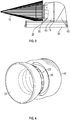
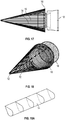
- a unidirectional hydrokinetic turbine having a water entrance end and a water exit end defining a direction of water flow through the turbine, comprising a generally cylindrical accelerator shroud section that defines within its cylindrical cross-section a water flow area; a rotor assembly that is mounted for rotation within the accelerator shroud around an axis that is generally parallel to the direction of water flow through the turbine, the rotor assembly comprising a plurality of rotor blades extending radially outwardly from the center of the turbine and a wildlife and/or debris deflector member mounted at the water entrance end of the accelerator shroud, the deflector comprising a generally conically-shaped structure which is tapered toward its forward/narrow end and comprises an array of deflector rods that run parallel to each other and are spaced essentially evenly at a pre-determined distance over their full-length with respect to one another, whereby the predetermined distance defines the maximum size of wildlife or an object that can pass through the deflector.
- the wildlife and/or debris deflector member includes at its forward/narrow end a ring member to which the deflector rods are attached, the ring having a diameter no larger than the pre-determined distance of the deflector rods.
- the ring member and/or at least some and preferably all of the deflector rods have a hydrofoil-shaped cross-section in order to reduce turbulence in the water flowing across the ring and/or deflector rods.
- a unidirectional hydrokinetic turbine having a water entrance end and a water exit end defining a direction of water flow through the turbine, comprising a generally cylindrical accelerator shroud that has a wall cross-section comprising a generally asymmetrical hydrofoil shape, which serves to accelerate the flow of water through the main accelerator shroud and to create a negative pressure field behind the accelerator shroud, in the direction of water flow, and that defines within its cylindrical cross-section a water flow area that contains an integral hydrokinetic force-generating member comprising a center hub member having an asymmetrical hydrofoil profile, and a plurality of blade members mounted on the hub member, wherein the force-generating member is mounted for rotation on the inner surface of the accelerator shroud.
- the turbine is characterized by its ability to accelerate the ambient flow velocity of the water entering the turbine to a flow velocity at the blade members that is at least about twice the ambient flow velocity, preferably at least about 2 1 ⁇ 2 times and most preferably at least about 3 times. Furthermore, the turbine is characterized by its ability to provide an increase in power output, compared to conventional hydrokinetic turbines of equal diameter, by a factor of at least about 25%, preferably by at least about 50% and most preferably by at least about 80%.
- a shroud that is designed for use in a unidirectional hydrokinetic turbine having a water entrance end and a water exit end defining a direction of water flow through the turbine.
- the accelerator shroud comprises a generally cylindrical accelerator shroud that has a wall cross-section comprising a generally asymmetrical hydrofoil shape, wherein the hydrofoil shape comprises a generally S-shaped profile in which the outer surface comprises a forward convex portion and a rearward concave portion, and the inner surface comprises a rearward convex portion and a forward portion that has a shape that is either straight or concave.
- This unique configuration serves to accelerate in an optimum manner the flow of water through the main accelerator shroud and to create a negative pressure field behind the accelerator shroud, in the direction of water flow.
- a unidirectional hydrokinetic turbine having a water entrance end and a water exit end defining a direction of water flow through the turbine, comprising a generally cylindrical accelerator shroud that has a wall cross-section that comprises an asymmetrical hydrofoil shape; and a rotor assembly that is mounted for rotation within the accelerator shroud around an axis that is generally parallel to the direction of water flow through the turbine, the rotor assembly comprising a plurality of rotor blades extending radially outwardly from the center of the turbine and a rotor outer ring to which the blade tips are attached for rotation within the accelerator shroud, wherein the blades have an asymmetrical hydrofoil-shaped cross-sectional configuration, with the blades most having either a cord length at their radially outer ends that is greater than the cord length at their radially inner ends, and/or a profile/cord thickness at their radially outer ends that is greater than the profile thickness at their radially inner ends
- the rotor assembly further comprises a center hub member, preferably with a generally round profile member having an asymmetrical hydrofoil profile, and the rotor blades are attached to the hub member.
- the hub member comprises a generally round profile member having an open center, with the wall members surrounding the open center forming an asymmetric hydrofoil profile, with the extrados being toward the outside of the turbine and the intrados facing toward the center of the hub.
- a wildlife and/or debris deflector member that is designed for use in a hydrokinetic turbine.
- the wildlife and/or debris deflector member is designed to be mounted at either end or both ends of a turbine.
- the deflector comprises a generally conically-shaped structure which is tapered toward one end and comprises an array of deflector rods that run parallel to each other and are spaced essentially evenly at a pre-determined distance over their full-length with respect to one another, whereby the predetermined distance defines the maximum size of wildlife or an object that can pass through the deflector.
- the wildlife and/or debris deflector member includes at its narrower end a first ring member to which the deflector rods are attached, the first ring hav ing a diameter no larger than the pre-determined distance.
- the deflector preferably has at or near its wider end a second ring member to which the deflector rods are attached.
- at least some and preferably all of the deflector rods and/or rings have a hydrofoil-shaped cross-section.
- a method for designing a unidirectional hydrokinetic turbine having a water entrance end and a water exit end defining a direction of water flow through the turbine comprising designing a generally cylindrical accelerator shroud that has a wall cross-section that comprises an initial asymmetrical hydrofoil shape and defines within its cylindrical cross- section a flow area, where the hydrofoil shape is selected based on fluid dynamics principles to serve to accelerate the flow of water through the accelerator shroud and to create a negative pressure field behind the accelerator shroud, in the direction of water flow; designing a rotor assembly that is mounted for rotation within the accelerator shroud around an axis that is generally parallel to the direction of water flow through the turbine, the rotor assembly comprising (i) a generally elongated cylindrical center hub having and a wall cross-section comprising an initial hydrofoil shape that is selected based on fluid dynamics principles; (ii) a plurality of rotor blades fixed to and extending radially outward
- the devices according to the invention are characterized by a unique flow acceleration system and other unique components, with no central shaft or gears and, as a result of these and other features, can operate at a higher efficiency level than other comparable turbines.
- hydrokinetic turbines of the invention are readily scalable in size, which means they can easily be adapted and optimized for any specific geographic area and for different flow speeds and flow volumes.
- the present invention includes several different installation methods, making the device suitable for usage in many different types of locations and conditions with any navigable water depth.
- the turbines of the invention are designed to be very environmentally friendly and to have practically zero impact on marine life, the seabed or riverbed and its surroundings. They are preferably equipped with wildlife and debris excluder, a safe passage or way through for small marine life and electromagnetic radiation (EMF) shielding.
- the exterior is preferably painted with non-toxic anti-fouling coating.
- the present invention in one aspect, relates to a hydrokinetic turbine intended to be placed underwater, in a fixed, floating, anchored or towed configuration, in a stream of water flow that preferably has a minimum flow speed of about 0.25 m/s.
- the invention also relates to certain turbine components, to a method for designing/producing such turbines, as well as to a method of using same. Of course this device will produce more energy with greater flow speeds.
- turbines may be installed in any numbers. They may be used as single units or may be installed as a “turbine array” or a “turbine farm” that may consist of multiple turbines and may be up to hundreds of units. The turbines may be generating electricity together or separately.
- the design of these turbines is scalable and may be produced as a small unit of any size, but practically speaking, at least about 30 cm of rotor section diameter, and may be any size of rotor section diameter that is practical and appropriate for a particular application at a specific location.
- the device may be a large unit of any size up to at least about 30 m of rotor section diameter or more.
- the invention provides an improved flow acceleration system developed by Applicant, that uses hydrofoil shapes on many of the key components of the turbine and most preferably on most or all of the components over which or through which the water flows.
- These components that may be hydrofoil shaped are called: the rotor blades (34), the center hub (36), the rotor blade shroud (38), the accelerator shroud (20), annular diffuser (40), the wildlife and debris excluder (10, 18), the tail rudder (60), the support structure (50, 52), the support piling (54).
- Some of these components can advantageously be hydrofoil shaped in order to optimize the extraction of energy, while other components such as the wildlife and debris excluders may be hydrofoil shaped in order to reduce or eliminate turbulence that could negatively affect another component or components.
- this hydrokinetic turbine can be adapted and optimized to the flow conditions of a specific site and to the size of turbine required.
- the changes to the hydrofoil shapes are advantageously made to one or more of the rotor blades, the accelerator shroud, the center hub and/or the annular diffuser.
- the changes, which in some cases can be relatively small and may consist in increasing or decreasing the cord length and/or the cord thickness of some hydrofoils and/or changing the angle of attack/incidence of the hydrofoils according to the speed of the water flow and the required size of the turbine.
- the output of the turbine will increase in proportion with the surface area of the rotor blades; this means that the driving force that determines how many kilowatts or megawatts a turbine produces is not in proportion to its diameter, but in proportion of the surface area of the rotor blades exposed to the water current.
- the output of a turbine increases by the square of the diameter; in other words a turbine that is twice as big in diameter will put out four times the electrical power. This property of the design makes the turbine scalable to almost any size that is practical and usable in a body of water with changes to the hydrofoil shapes which are often relatively minor changes.
- the designs according to the invention achieve a very large increase in flow speed through the rotor section of the turbine where the hydrofoil shaped blades are positioned. No other known hydrokinetic turbine design has achieved this degree of flow acceleration.
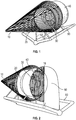
- the invention is preferably composed of four main components, a) a flow accelerator shroud, b) an optional annular diffuser following the flow accelerator shroud, c) a main rotor which is built into the accelerator shroud but is a separate part, and d) one or more optional wildlife / debris excluders.
- Some of these components typically comprise several different sub-parts that are assembled to be one part of the turbine. Additional features and advantages are described below. These parts and features cooperative with and have an effect on one another in ways that are also described below to produce the improved operation of the turbines according to the invention.
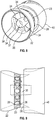
- the flow accelerator shroud (20) is an important part that embodies the most complex hydrofoil shape. As used in the designs of this invention, it preferably has an asymmetrical hydrofoil shape and most preferably an S-shaped/double-curved hydrofoil shape ( Fig 5a , 21 ), or in other words a generally S- shaped double-curved configuration ( Fig. 9 ), to create a negative pressure field behind the shroud in order to accelerate the water flow through the rotor section (30) of the turbine.
- the cross-section of the wall of the accelerator shroud may also be a hydrofoil shape that is not an S-shaped double-curved, but resembles much more conventional hydrofoil shapes ( Fig. 5 b , 24 ).
- the accelerator shroud accelerates the flow of the water on the inside of the turbine in comparison to the ambient flow speed around outside the accelerator shroud.
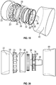
- the accelerator shroud is preferably composed of four pieces: entrance duct (22), the stator housing (24), the rotor blade shroud (38) ( Fig. 10 ) and the aft fairing (28).
- These four components together preferably form a single shape, which is preferably the asymmetrical hydrofoil of the accelerator shroud, which in certain preferred embodiments has the S-shaped/double-curved hydrofoil shape. All four pieces are preferably faired together to form a perfectly smooth surface both inside and outside, over which the water flows without creating any significant turbulence.
- the entrance duct (22) serves to funnel the water flow into the rotor section (30) and to lead the water flow onto and over the stator housing (24) on the outside of the accelerator shroud and over the rotor blade shroud (38) on the inside.
- This stator housing exterior surface and the rotor blade shroud interior surface are part of the overall shape of the accelerator shroud.
- the entrance duct also contains the forward thrust bearings that guide the rotor section during operation.
- the stator housing (24) contains all the metallic, preferably copper, coils (25) that comprise the stator of the annular generator, as well as the conventional electrical wiring (not shown) to convey the electrical energy generated out of the turbine.
- the stator housing also contains the rotational roller/ball bearings (or other bearings or low friction polymer bushings) (26) on which the rotor section rotates.
- the exterior surface of the rotor blade shroud (38) forms part of the accelerator shroud but is a separate part that is attached to the rotor blade tips (33) and rotates with the main rotor inside the accelerator shroud. It is described in more detail below.
- the aft fairing also contains the aft/rearward thrust bearings (26) ( Fig. 9 ) against which the rotor section is pushed while rotating.
- the annular diffuser (40) is also preferably an asymmetrical hydrofoil shaped ring and preferably has a greater diameter than the accelerator shroud (20).
- the annular diffuser (40) is located behind the accelerator shroud and preferably overlaps somewhat over the aft end of the accelerator shroud (20). It works in a manner very similar to the accelerator shroud, further increasing the negative pressure field behind the turbine. Because of the cooperation and resulting synergistic effect of the accelerator shroud and the annular diffuser, there is a greater augmentation of flow speed through the rotor section.
- the rear wildlife and debris excluder is attached at a position relatively closely (e.g., from about 4 to 6 inches) behind the trailing edge of the (final) annular diffuser, which is preferably a feather edge.
- the rear wildlife and debris excluder is attached at a position relatively closely (e.g., from about 4 to 6 inches) behind the trailing edge of the (final) annular diffuser, which is preferably a feather edge.
- the hydrokinetic turbines of the invention preferably have an open center (37).
- this is advantageous in the designs of the present invention because of the low speed that the blades travel through the water near the center of the rotor section and therefore do not create sufficient lift or enough energy worth extracting.
- the center portion generally has a negative effect on the rotor due to the extra drag it creates by a larger wetted surface and additional weight needing to be moved through the water.
- the extremities of the rotor blades (34) travel through the water at a higher speed and therefore create substantially more lift and allow substantially greater energy extraction.
- the ratio between open center and blade and hub size can be anywhere from about 40% blade:60% open space, to about 80% blade:20% open space.
- Turbines according to the invention advantageously use the major portion of the overall diameter along the perimeter of the rotor section to produce lift, typically more than about 60% and more preferably approximately 2/3 of the diameter. This leaves the remaining minor portion, e.g., in a preferred embodiment approximately 1/3 of the overall diameter in the center open (37). Eliminating the center section of the rotor reduces the overall weight of the rotor and also reduces the wetted surface area and drag that a solid profile section would create.
- the designs of this invention create a more efficient rotor section that uses a smaller blade area with less weight, with less wetted area and less drag, which can rotate at higher rpm rates and allow more energy to be extracted.
- a secondary effect that is of further benefit to the wildlife and debris excluder that is described below.
- the center hub (80) that is solid preferably has a symmetrical hydrofoil shape, whereas the center hub 36 with open center preferably has an asymmetrical hydrofoil shape, with the extrados being toward the outside of the turbine and the intrados facing toward the center of the hub.
- the lift created by the center hub helps further increase the negative pressure field behind the turbine created by the accelerator shroud (20) and the annular diffuser (40). This effect increases the acceleration of the water flow through the rotor blade section and contributes to the synergistic effect and resultant higher power generation.
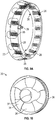
- the rotor blade shroud (38) (also called the outer ring of the main rotor) is where the extremities/tips (33) of the blades (34) are attached. ( Fig. 10 )
- This rotor blade shroud (38) forms a part of the hydrofoil shape of the accelerator shroud (20). It is a separate element from the accelerator shroud allowing it to rotate with the rotor blades (34). but the surface of the rotor blade shroud is preferably perfectly in line with the inside surface of the accelerator shroud (20) to create one smooth curve of both inside surfaces, accelerator shroud and rotor blade shroud.
- the outside surface of the rotor blade shroud which faces the stator housing (24) interior surface, is preferably recessed into the accelerator shroud and has a flat surface where the permanent magnets (32) are located which rotate past the copper coils (25) of the stator to produce the electrical energy.
- the rotor blade shroud (38) also eliminates tip vortex and reduces drag and turbulence, resulting in higher efficiency and greater energy extraction.
- the efficiency of the rotor blades (34) is increased by preferably using an asymmetrical hydrofoil shape, which is also preferably optimized, as explained below.
- This shape also called the cord or cross-section (35) of the hydrofoil, results in an increase of the efficiency of each blade, reduces it in size and decreases the number of blades relative to other designs.
- a smaller rotor blade (34) has less wetted area, thus producing less drag.
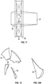
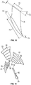
- the amount of lift a hydrofoil shape generates is determined by the shape of cord/cross-section (35) ( Fig. 15 ), the length of cord (74) and the thickness of cord (76) of the hydrofoil. ( Fig.
- the length of cord (74) and/or the thickness of cord (76) preferably change between the blade root (39) and the blade tip (33). This optimizes the lift created by the hydrofoil shape in relation to the speed it travels through the water.
- the number of blades put into the rotor section of designs according to the invention may vary depending on the size of the turbine and the flow speed of the water in a particular application.
- the angle/incidence (72) ( Fig. 13 ) at which the rotor blades are installed is also a variable that can be adjusted for the purpose of optimizing the angle of attack or incidence of the blade traveling through the water. It is preferred to use an optimum angle which is determined by the rpm of the rotor to produce a laminar or at least a near laminar flow of the water over the blade surface. If this flow is turbulent or significantly non-laminar, the hydrofoil creates less lift, and therefore less energy can be extracted. The tip of the blade travels through the water faster than the root of the blade, due to the fact that it travels a longer distance to complete one rpm.
- the incidence of the blade advantageously decreases gradually from the root (39) of the blade to the tip (33) of the blade, in order to be at the optimal angle.
- This change in angle is called the twist (78) of the blade.
- the twist is preferably designed to create a rotor blade maximum lift at every cross-section and therefore to increase the efficiency and the power extraction.
- hydrofoil shapes according to the invention In order for hydrofoil shapes according to the invention to be optimal while they travel through the water at different speeds, they preferably have different lengths of cord (74) and different thicknesses of profile/cord (76).
- the thickness (76) of the blade increases and/or the cord length (74) increases from the root of the blade toward the tip of the blade, in order to increase the surface area where the blade travels though the water with higher speed and creates the greatest amount of lift.
- the blades most preferably increase in both size and thickness as they extend radially from the hub. These increases in cord length and thickness result in higher efficiency and greater power extraction.
- the rotor blades hydrofoil shape (35), the length of cord (74), the thickness of profile/cord (76), the degree of incidence (72), and the twist (78) of each rotor blade, and the number of blades can advantageously be varied for each application, in order to adapt to site-specific flow conditions of the water and other locational needs.
- a hydrokinetic turbine that produces energy from a renewable source with zero carbon emissions should be environmentally friendly not only to the natural resources and to the atmosphere, but also to marine and wildlife.
- This invention deflects and keeps any marine life and floating or submerged debris above a specified size out of the hydrokinetic turbine's rotor of the invention.
- the size of marine life or debris that cannot enter the nozzle section of the turbine is specified by the spacing/distance (15) of the deflector rods (14) of the forward and rear excluder.
- the deflector rods by design, run parallel to each other and are evenly spaced over their full-length to ensure that no distance between the rods (15) is greater in one place than in another.
- the distance of the spacing (15) is determined by the size and the species of marine wild life as well as the size of debris encountered to be excluded and to adapt to locational needs of specific sites of operation. It will prevent any sea life such as fish, turtles, sea mammals and even divers that are larger than the space (15) between the deflector rods (14) from entering into the rotor section of the hydrokinetic turbine from the front as well as from the back when a rear excluder is also employed.
- Some other prior art devices are designed as concentric circular deflector rods (see, e.g., US D 304,322 and US 5,411,224 ) which define a finite size of opening, but such configurations do not effectively shed off all wildlife and debris like the deflector rods according to the present invention, which are aligned obliquely with respect to the flow direction. In the concentric design, wildlife or debris can easily become lodged between the rings. In the designs of the invention, the exact size of marine life or debris to be excluded can advantageously be selectively predetermined by the distance (15) chosen between the deflector rods (14).
- Ocean currents and river currents contain floating debris of many sorts. This debris may be floating at the surface or submerged at different depths. Therefore, it is preferred to keep such debris out of the rotor section of the hydrokinetic turbine to the greatest extent possible, in order to prevent damage to the turbine and to ensure continuous and uninterrupted electrical output.
- the designs according to the invention effectively deflect and keep out any debris above the specified size (15) of the spacing of the deflector rods.
- the hydrokinetic turbines according to the invention preferably have two wildlife and debris excluders, one (10) in front at the entrance (22) of the turbine and one (18) behind at the exit of the turbine.
- the front wildlife and debris excluder (10) is located in front of the turbine protecting the entrance (22) of the accelerator shroud (20), and is attached to the front end of the accelerator shroud as well as preferably to the support structure (50, 52) of the turbine.
- the deflector rods (14) of the excluder may be made of metal, fiberglass or synthetic materials with different diameters depending on the turbine size; from about 1 ⁇ 4 inch on a small turbine and up to about 2 inches on very large units.
- the deflector rods are preferably hydrofoil/teardrop (14) shaped in cross-section ( Fig.
- This configuration serves to avoid turbulence in the water flow that could disturb the efficiency of one or more other components, such as the accelerator shroud (20), the annular diffuser (40) and/or the rotor blades (34).
- the first/forward wildlife and debris excluder (10) is preferably built so that the deflector rods on the forward end of the front excluder (14) form a generally cone-like shape.
- the deflector rods on the forward end are attached to a small ring (12) that preferably has the same inside diameter as the specified distance (15) between the insides of the deflector rods.
- the deflector rods are preferably attached to a large ring (16) which is preferably greater diameter than the annular diffuser (40).
- the slope of the cone-like shape created by the difference between the forward ring (12) and the aft ring (16), to which the deflector rods (14) are attached, can be altered to adapt to different environmental needs.
- the front excluder is preferably positioned so as to slightly overlap the annular diffuser with a gap that is approximately the same size as the distance (15) between deflector rods, in order to maintain a finite size of wildlife and debris allowed to enter, it is designed to be cone-like shaped in order to shed off and divert any wildlife, debris, sea grass or whatever else may be floating in the stream of water about to enter the turbine.
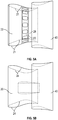
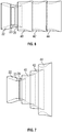
- the second/aft wildlife and debris excluder 18 ( Figs. 16 and 18 ) is located behind the turbine exit and is attached to the trailing edge of the (final) annular diffuser.
- the rear excluder is preferably also comprised of a grill or mesh of parallel rod members that are spaced apart from one another by the same pre-determined distance as the rods (14) in the front excluder, and in the case of the rear excluder, the most preferred configuration is a generally planar one.
- the rear excluder prevents larger sea life from entering into the rotor section from behind, even against the direction of the water current or also in the case of no current as for example during the change from an incoming to an outgoing tide.
- the deflector rods of the excluder are spaced to the same specified distance (15) as the forward wildlife and debris excluder to prevent any wildlife or debris larger than the specified distance from entering into the rotor section.
- All the deflector rods (14) of both of the excluders preferably have a hydrofoil shaped cross-section, to minimize the creation of turbulence and vortices that would negatively affect hydrofoil shapes that may be present on one or more of the other components, such as, the rotor blades, the accelerator shroud, the annular diffusers, and/or the center hub.
- the smaller sea life that can pass through the spacing (15) of the deflector rods is advantageously provided a secondary path for safe passage through the cylindrical center hub (36) having an open center (37) in the majority of the depicted turbine embodiments.
- the open center of the rotor section is described above. Because the water flow speed in the center hub is taster than outside where the blades are situated, smaller sea life will be aspirated through that opening and can exit unharmed.
- the diameter of the open center may vary widely, without materially affecting the performance of the turbine. The optimum diameter can be calculated for each application, and in certain preferred embodiments is typically approximately 1/3 of the overall diameter of the rotor section.
- the accelerated flow of the water through the open center (37) serves to safely convey small wildlife and small debris through the inside of the turbine.
- the turbines according to the invention are preferably automatically self-orienting, meaning that they will always point exactly into the direction from which the water flow is coming.
- This is preferably achieved by the installation behind the turbine of a fixed tail rudder (60), which is preferably hydrofoil shaped and will orient the unit directly into the direction of the stream of water flow.
- a fixed tail rudder 60
- This feature allows the device to point exactly into the direction from which the current is coming, so that the water passing over the hydrofoil shaped components of the turbine flows at the optimal angle over all hydrofoil shaped surfaces. This optimizes the pressure differential between the two sides, increases the synergistic effect of the hydrofoil shapes and helps to assure a laminar flow of the water.
- the design of the hydrokinetic turbines of the invention is such that the flow of the water is always from the same side, i.e., unidirectional. This allows the turbines to take great advantage of many asymmetrical hydrofoil shapes and hydrodynamic effects, which, when combined together, result in a much more efficient turbine. Bi-directional turbines cannot use asymmetrical hydrofoil shapes, and are therefore less efficient.
- the turbines according to the invention do not only utilize the Venturi/Bernoulli effect much better due to their unidirectional flow, but they also increase the flow velocity further with the use of the preferred asymmetrical hydrofoil shaped accelerator shroud and/or annular diffuser. and/or the preferably hydrofoil shaped center hub.
- the annular generator design preferably has magnets (32) mounted on the rotor blade shroud (38) and copper or other metallic coils (25) in the stator housing (24) which is preferably located inside the accelerator shroud (20).
- This design eliminates the need for a gearbox or transmission or hydraulic systems to mechanically extract and convey the energy out of the turbine. Gearboxes, transmissions and hydraulic systems create friction that consumes a portion of the energy that the turbine produces. By the usage of an annular generator, the invention minimizes these friction/transmission losses and creates a more efficient turbine or generator.
- the electrical energy generated directly inside the turbine is transmitted through electrical wires (not shown) eliminating friction/transmission, and power losses.
- the energy produced is then transmitted for conditioning to an inverter/transformer that typically is located outside the turbine, wherever deemed practical.
- the preferred design according to the present invention also eliminates the need to have center bearings, which thereby eliminates the need for any fixed structure whatsoever (e.g., shaft or hub) located within the flow area through the turbine.
- the absence of any fixed structure furthermore means that no struts or other elements are needed to support that fixed structure.
- the accelerator shroud (20), the annular diffuser (40), the hydrofoil shaped center hub (36, 80) and the rotor blades (34) of this turbine are preferably constructed of composite building materials, such as, e.g., carbon fiber, aramid fiber, fiberglass or similar in either solid fiber and resin or over structural foam core material or honeycomb core material.
- Some parts such as the stator housing are preferably hollow to accommodate the copper coils (25) of the stator.
- Other parts such as the entrance duct (22), the aft fairing (28) of the accelerator shroud (20) and the annular diffuser (40) may in some preferred embodiments be solid or sandwich construction and remain hollow on the inside, with the option to be selectively filled with water when submerged.
- the preferred self-orienting feature of the device allows this turbine to be a unidirectional flow turbine.
- a unidirectional turbine the existence of a water flow that is always coming from the front of the turbine allows the use of asymmetrical or unidirectional hydrofoil shapes in the design.
- any or all of the basic components, i.e., the rotor blades, the accelerator shroud, the annular diffusers, the hollow center hub, the tail rudder and/or the wildlife and debris excluders can advantageously comprise, to at least some degree, asymmetrical hydrofoil shapes.
- the asymmetrical or unidirectional hydrofoil shapes are much more efficient than symmetrical and bidirectional hydrofoils.
- This synergistic effect creates a greater acceleration of the flow through the rotor section where the asymmetrical hydrofoil shaped blades take greater advantage and are able to rotate at higher speed or RPM.
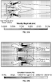
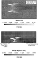
- the table shows how, for one preferred embodiment, the presence of the hydrofoil shaped accelerator shroud results in an exponential acceleration of the flow velocity through the nozzle section, compared to the ambient flow speed.
- the data represented in Figure 36 illustrates the difference in power output with increased ambient current velocity for between 2 different designs of hydrokinetic turbines with a 1.5 meter diameter rotor.
- the line with squares represents a hydrokinetic turbine that simply has a hub and 3 blades, with no shroud that all (which is the most commonly used design used in hydrokinetic turbines worldwide).
- the line with triangles demonstrates the output of the present invention that utilizes hydrofoil shaped accelerator shroud, annular diffuser and open center hub. This is the same relationship for the same rotor assembly contained within an accelerator shroud having a hydrofoil shape similar to that depicted in Figure 35 . It is seen that the increase in power is according to an exponential power on the order of 3.
- the hydrokinetic turbines according to the invention can be installed in practically any moving body of water or can be moved through the water to create usable output.
- the turbine unit or units can be a piling mounted installation, which consists of a piling (52) driven into the ocean floor or riverbed that has a set of rotational thrust bearings and a compression pivoting bearing on the top (53).
- the mounting structure (50) can unbolt from the pipe (52) and has an electrical plug (53) inside the pipe that can be unplugged for maintenance and turbine removal.
- This installation allows the turbine unit to pivot and the turbine can freely rotate 360° to orient itself exactly into the direction of the water current.
- This type of installation also has a very small seafloor footprint and minimal impact on the environment.
- the electrical power is transmitted through a set of copper rings and charcoal brushes (53) inside the sleeve to avoid a cable being twisted and any restraint on the pivoting action.
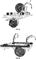
- Floating structure-mounted ( Figs. 23, 24 , 25. 26 , 27 ):
- the turbine unit or units can be attached to any kind of floating structure such as an ocean barge, a raft (54), a ship or a vessel floating on the surface of the water.
- These devices can either be anchored to the seabed or riverbed (59) or held in place by thrusters coupled to GPS location devices similar to oil rigs or tied to any structure in the ocean or in a river or along shore.
- the raft mounted device either employs a hoisting system or a crane that is installed on deck or a helical gear driven device to pivot the turbine onto the deck.
- a hoisting system or a crane that is installed on deck or a helical gear driven device to pivot the turbine onto the deck.
- the transversely mounted system employs two rafts or barges, with the turbine unit mounted in between them.
- one type of installation can be better than the other.
- the turbine or turbines can be mounted over the side of the floating structure and be pivoted on the longitudinal axis ( Fig. 23, 24 , 25 ), to be placed on the deck of the structure for maintenance or repair.
- Land-based structure-mounted ( Fig. 28 ):
- the turbine unit or turbine units can also be mounted to a land-based structure such as a seawall, a shoreline or be attached to a bridge pillar or other structures installed in the stream of an ocean current or in a river current.
- the device can preferably be mounted on any of these fixed structures by at least two different methods.
- Support structure to which the turbine is attached can be mounted either to one or two rails attached to the fixed structure on which the unit is lowered into the water and raised up out of the water for maintenance or repair, or it can be mounted on a pivot which also allows the device to be pivoted into the stream of water and back out of the water for maintenance or repair. Either way, the units are held in place in the up position by a latching mechanism, whereas in the down position it can rest on some end stops.
- the cable connection preferably goes to the base structure and from there to a transformer for conditioning.
- the turbine unit or turbine units can be made naturally buoyant due to the composite construction materials that can be employed for the construction of any or all the parts. This allows the device to float at any given depth determined by the length of a tether (64 & 66) which is attached to a foundation/seabed mooring (59) or screw-type anchor, or any other fixed device on the seabed or the riverbed.
- the two-part tether serves two purposes: the fixed tether (64) and the rolling tether (66) is to hold the device submersed at the desired depth and to transmit electricity from the generator unit to the base and then to shore.
- This tether (64 & 66) has 2 components; a primary fixed tether (64) that is a fixed length between the turbine and the secondary rolling tether (66) which is a rolling mechanism that is attached to the base and is the equal in length to the distance between the water surface and the desired depth where the turbine is to be held.
- a primary fixed tether (64) that is a fixed length between the turbine
- the secondary rolling tether (66) which is a rolling mechanism that is attached to the base and is the equal in length to the distance between the water surface and the desired depth where the turbine is to be held.
- the dev ice may also be attached on a submersible raft (58) or submerged flotation device (58), to hold the turbine suspended in midstream.
- the same tether mechanism can be utilized in this case.
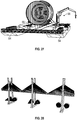
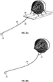
- Towed installation ( Fig. 30 ):
- the turbine unit or turbine units can also be towed behind a vessel or be dragged through the water by other devices that propel the device through water that is not moving, to artificially create a water flow through the device.
- the towing cable is typically attached to the front of the wildlife and debris excluder, and therefore would orient the turbine to optimally create the flow from front to back through the unit.
- hydrokinetic turbines of the invention require only minimal maintenance, due to the design of the components and because the preferred composite construction materials are virtually corrosion free. However just like everything that is submersed in the ocean over a certain length of time fouling and marine growth will occur. These hydrokinetic turbines are coated with non-toxic antifouling paints, but still need periodic cleaning of the surfaces to ensure optimal functionality and output. These units can be pressure washed by a diver while they are submerged which allows them to remain underwater or they can be brought to the surface and be pressure washed by ground personnel. Other than periodic cleaning, these units require very little maintenance. Depending on the type of installation, the preferred maintenance procedures may vary, as discussed below.
- a special maintenance vessel (also designed by the Applicant) that is a catamaran vessel having a removable deck between the two hulls, and a gantry with a hoist installed over that removable deck.
- the vessel can be positioned above the turbine that needs maintenance, and the turbine unit can be lifted by reaching through the opening in the deck between the two hulls and hoisting the turbine onto the boat.
- the electrical wire connecting the turbine to shore leads to copper rings and brushes (53) that are located inside support piling for pivoting (52) has a waterproof plug (53) that can be unplugged when the turbine is lifted up by the maintenance vessel located above.
- the turbine that was just removed from the piling can be put off to one side, onto one of the hulls, and a spare turbine sitting ready on the other hull can be lowered through the opening and plugged and bolted back onto the piling, from which the first unit was removed.
- a support structure (55) is used that is mounted on pivot points with bearings (55), which allow the unit to pivot around a central axis either 270° in the case of longitudinally mounted units ( Fig. 23, 24 , 25 ), or 180° in the case of transversely mounted units ( Fig. 26 , 27 ).
- a locking mechanism is used to hold the units in place when submerged for power generating, as well as when surfaced for maintenance or repair.
- a crane or hoist (56) installed on the raft is employed that can attach to the support structure of the turbine. Once unlatched in the submerged position, the crane can pull the unit out of the water by pivoting the unit into the maintenance position where it can be secured by latching into position.
- the turbine units can be maintained or repaired by at least two methods.
- One method is to have a floating platform or raft that is put in place after the turbine is hoisted out of the water, either by sliding the turbine mounted to the support structure upwardly on the rails of the fixed structure, or to make the units mounted on the support structure upwardly out of the water.
- the other procedure is to have a platform that is attached to the fixed structure that can swing out of the way for raising the turbine units out of the water and then be repositioned for servicing.
- the towing line attached to the turbine unit is hauled in to bring the turbine unit alongside or behind the vessel, where it is typically picked up by a hoist or a crane mounted on the vessel.
- the turbine is then preferably placed on the deck of the vessel for maintenance or repair.
- the application also describes design modifications intended for embodiments designed for a 6 kn current, as being representative of and also exemplifying turbines intended for use in environments exhibiting these higher current flow velocities. Therefore, the application describes embodiments that are representative of designs for use at these two most (i.e., nearly all) commonly encountered flow speeds.
- the turbines according to the invention can be optimized for any flow speed, which from a practical standpoint includes currents ranging from about 1 ⁇ 2 kn to up to about 12 kn of flow speed.
- the present invention utilizes these algorithms/databases in a novel design regimen, as a starting point to design novel hydrofoil shapes that serve as the so-called "initial" designs in the first stages of the hydroturbine design process.
- the design process typically starts out with hand-drawn sketches (usually but not necessarily novel) based upon conventional fluid dynamic considerations, which sketches are selected based upon the novel principles according to this invention.
- the selected sketches are subsequently entered into a computer program of the type called a 3-D modeling program, one example of which is called "Rhino 3-D” or "Sol id Works”. This results in a first version of the "initial" designs.
- the first version of the "initial" design can be produced by selecting various different hydrofoil shapes from one of the databases, such as the archives of the National Advisory Committee for Aeronautics (NACA), again based upon the same conventional fluid dynamic considerations that are employed in fashioning the hand- drawn sketches, but again the shapes are selected (from among a huge number) based upon novel design considerations taught in this application.
- the shapes of these first version, "initial" intuitive hydrofoil shapes are modified with the 3-D modeling software, such as Rhino 3D or SolidWorks and analyzed in a 2-D flow analysis program, such as "Java Foil” or the like, and other similarly commercially available software products for this purpose.
- the size of hydroturbines according to the invention can be scaled up or down with typically only minor changes in the overall configuration.
- the main influencing factor of the choice of an "initial" hydrofoil shape, and then the further modification of that profile, is the flow speed of the water current in which the turbine is to be placed.
- the cross-section of the hydrofoil shapes are generally more slender and flatter (less camber on both sides of the hydrofoil) then they are in a profile design for a 3 kn current, where the cross-section of the hydrofoil would be more curved and thicker (more camber on both sides of the hydrofoil).
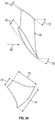
- Figure 33 the differences in the respective cross-sections or profiles are clearly visible.
- the cord of the hydrofoil shape is also often increased.
- the rotor blade shape is designed in the same fashion as the center hub and accelerator shroud.
- a suitable "initial" hydrofoil shape is sketched or chosen from the library, for the cross-section of the rotor blade, in accordance with the principles of the invention, and then modified (utilizing fluid dynamics principles) based upon the speed with which it travels through the water, which speed is greater at the tip of the blade than at the root of the blade.
- the hydrofoil cross-section of the rotor blade, the length of cord, the thickness of the cord/profile and the incidence of the cross-section each preferably changes, more preferably changes continuously, from the root of the blade out to the tip of the blade.
- the program creates an elaborate mesh of polyhedral shapes to simulate the fluid volume and a very precise shape of the turbine in the form of a mesh composed of millions of triangles. Afterwards, this newly created model is run through the solver of the program, which analyzes the fluid/water flow (polyhedral bodies) over the turbine shape (triangle mesh) and shows the flow paths created by it. In this way, the final optimized shapes and configuration of the components are arrived at by making changes and assessing the consequences of those changes based on the testing feedback provided by CFD analysis, until a final optimum combination of shapes is achieved.
- the target is considered to be what is theoretically believed to be the maximum possible improvement in results, for example, an increase in flow speed through the turbine of about three times the incoming, ambient current velocity.
- a target of a certain improvement in turbine power output compared to known, comparably sized turbine, can be chosen.
- optimization is considered to be achieved.
- Figures 34 and 35 the essential dimensions are shown for one preferred embodiment of a turbine according to the invention, namely, a 1.5 meter diameter turbine that has been optimized for use in a current having a speed in the region of 3 knots as shown in the following Legends.
- stage ill of the development begins.
- This stage is the physical building of a fully functional prototype and testing in real-life conditions while monitoring and documenting all parameters of the design. This involves recording of rpm of the rotor section, electrical output of the turbine unit, video recording of the flow characteristics through tufting of all surfaces (similar to an airplane wing in a wind tunnel). These tests are conducted at various different flow speeds from 1 kn up to 6 kn utilizing various configurations of accelerator shroud shapes annular diffuser shapes and rotor section shapes. Ultimately this test results, in final confirmation of the functionality and efficiency of the design for a given flow speed and a specific turbine size.
- the first step of site-specific design consists of flow data collection of the characteristics at a specific location or site.
- the flow speeds, the flow direction, the flow mass characteristics (volume of water flowing at any specific time) and the fluctuations in flow over a given period of time will be precisely measured and recorded with the aid of acoustic Doppler equipment.
- the second step is to assess, log and record the types and quantities of sea life and wildlife in the area chosen for the installation site by prolonged video recording, diving and logging of all the species and size of sea life. It is also necessary to log the type and quantity of debris floating in the water.
- an optimized turbine for a specific site can be developed by first slightly adjusting the hydrofoil shape of the accelerator shroud, the diffuser, the center hub and the rotor blades, and then adjusting the spacing of the bars on the wild life and debris excluder to the local needs. This will assure that no wildlife is harmed by the turbine, that the turbine does not get harmed by floating debris, and that the maximum amount of energy/electricity can be extracted at the precise location.
- the Applicant has conceived of certain novel designs for hydrokinetic turbines, has furthermore taken concepts, tools and information from a number of different fields, and has employed and/or combined them in a novel manner to design unidirectional hydrokinetic turbines that exhibit a significantly higher efficiency.
- This is due largely to the synergistic interaction of multiple, novel turbine components that embody novel asymmetric hydrofoil characteristics, which have been fine-tuned in a new way for the specific environment in which they are to be employed.
- the "Novelty of Design Process” is evident because never before have engineers and designers been able to achieve the highly efficient results as demonstrated in connection with the hydrokinetic turbines according to the present invention.
- hydrokinetic turbines and/or components are unique because of the fact that no other design up until the present has combined every possible hydrodynamic advantage, let along in novel combinations (in component selection, component design and interaction of these components together) to optimize the output of the turbine and accelerate the flow of the water to extract more energy as is possible with the turbines of the present invention.
- hydrodynamic principles are well known, the use of these principles and the combination of novel designs and the effects of all the different elements used in this design, especially the mutually beneficial and synergistic effects of these elements combined together, are new and inventive.
- each and every element is initially designed and then optimized for the flow speed and size of turbine, and therefore the end result is a hydrokinetic turbine with much greater output and efficiency than other designs proven up to present.
Applications Claiming Priority (2)
| Application Number | Priority Date | Filing Date | Title |
|---|---|---|---|
| US201562115540P | 2015-02-12 | 2015-02-12 | |
| PCT/US2016/017857 WO2016130984A2 (en) | 2015-02-12 | 2016-02-12 | Hydroelectric/hydrokinetic turbine and methods for making and using same |
Publications (2)
| Publication Number | Publication Date |
|---|---|
| EP3256717A2 EP3256717A2 (en) | 2017-12-20 |
| EP3256717B1 true EP3256717B1 (en) | 2021-01-06 |
Family
ID=55949063
Family Applications (1)
| Application Number | Title | Priority Date | Filing Date |
|---|---|---|---|
| EP16721272.9A Active EP3256717B1 (en) | 2015-02-12 | 2016-02-12 | Hydroelectric/hydrokinetic turbine and methods for making and using same |
Country Status (13)
| Country | Link |
|---|---|
| US (3) | US10294913B2 (ru) |
| EP (1) | EP3256717B1 (ru) |
| JP (1) | JP6962816B2 (ru) |
| KR (1) | KR102358885B1 (ru) |
| CN (1) | CN107429656A (ru) |
| AU (3) | AU2016219073B2 (ru) |
| BR (1) | BR112017017356A2 (ru) |
| CA (1) | CA2976226A1 (ru) |
| DK (1) | DK3256717T3 (ru) |
| MX (1) | MX2017010416A (ru) |
| RU (1) | RU2742012C2 (ru) |
| WO (1) | WO2016130984A2 (ru) |
| ZA (1) | ZA201706028B (ru) |
Families Citing this family (20)
| Publication number | Priority date | Publication date | Assignee | Title |
|---|---|---|---|---|
| CN106373449B (zh) * | 2016-10-18 | 2019-01-29 | 浙江海洋大学 | 一种模拟海上作业工况的海洋工程试验平台装置 |
| US9909560B1 (en) * | 2017-06-22 | 2018-03-06 | Daniel F. Hollenbach | Turbine apparatus with airfoil-shaped enclosure |
| EP3706881A4 (en) * | 2017-11-09 | 2021-06-30 | Hydrokinetic Energy Corp. | ACCELERATED AND / OR DEFLECTED FLOW INDUCTION AND / OR LOW PRESSURE FIELD / AREA INDUCTION ARRANGEMENT, THE USE OF IT WITH TURBINE-TYPE METHODS OF USE |
| IT201800004645A1 (it) * | 2018-04-18 | 2019-10-18 | Zupone Giacomo Francesco Lo | Macchina cinetica modulare per la produzione di energia da correnti fluide |
| CN108644058A (zh) * | 2018-07-11 | 2018-10-12 | 重庆同利实业有限公司 | 一种超低水头水力发电机 |
| KR20210113338A (ko) | 2019-01-18 | 2021-09-15 | 텔레시스템 에너지 리미티드 | 에너지 생성 터빈을 포함하는 회전 기계를 위한 수동 자기 베어링 및 상기 베어링을 통합하는 회전 기계 |
| CN113574268A (zh) * | 2019-03-14 | 2021-10-29 | 泰利西斯特姆能源有限公司 | 用于流体动力涡轮的多级段罩部 |
| KR102065550B1 (ko) * | 2019-03-29 | 2020-01-13 | 김상기 | 조력 또는 파력 발전을 위한 회전 장치, 이를 이용한 발전기 및 발전 기능을 가진 콘크리트 블록 |
| EP3959434A4 (en) * | 2019-04-22 | 2023-03-29 | Michael Scot Cummings | CONTINUOUS FLUID FLOW POWER GENERATOR |
| WO2021001802A1 (en) * | 2019-07-03 | 2021-01-07 | Nemat Keramat Siavash | A wind turbine augmented by a diffuser with a variable geometry |
| US11560775B2 (en) * | 2019-10-01 | 2023-01-24 | Brandon Bullock | Catwalk fluid and ground protection recovery system |
| US20210127940A1 (en) * | 2019-11-04 | 2021-05-06 | Haier Us Appliance Solutions, Inc. | Pump assembly for a dishwashing appliance |
| EP4069970A1 (en) * | 2019-12-04 | 2022-10-12 | Michael Scot Cummings | Reactive, reversible blade turbine for power generation and pumping water |
| CN111271206B (zh) * | 2020-02-27 | 2020-12-11 | 中国科学院声学研究所 | 一种用于深海潜标能源补充的微弱海流发电系统 |
| JP7335845B2 (ja) | 2020-03-25 | 2023-08-30 | Ntn株式会社 | 水力発電装置 |
| EP4150202A4 (en) * | 2020-05-13 | 2023-11-15 | Natel Energy, Inc. | BEHAVIORAL GUIDANCE SYSTEM FOR FISH |
| CN112065639A (zh) * | 2020-09-24 | 2020-12-11 | 沈荣华 | 一种海洋可再生能源综合利用的浮式发电装置 |
| CN112796919B (zh) * | 2020-12-30 | 2022-05-24 | 浙江大学 | 一种高效率双转子电机结构的潮流能发电装置 |
| CN113482842A (zh) * | 2021-07-27 | 2021-10-08 | 潍坊新力蒙水产技术有限公司 | 一种双向海流发电系统 |
| CN116447081B (zh) * | 2023-04-14 | 2023-10-10 | 广东永光新能源设计咨询有限公司 | 可再生能源类型的发电装置 |
Family Cites Families (64)
| Publication number | Priority date | Publication date | Assignee | Title |
|---|---|---|---|---|
| US1123491A (en) * | 1913-05-12 | 1915-01-05 | Elbert A Corbin | Power-conversion plant. |
| US1713446A (en) * | 1928-07-05 | 1929-05-14 | Peterson Gabull | Propeller guard |
| US2620635A (en) * | 1950-09-09 | 1952-12-09 | Erwin W Mautner | Cooling system and control |
| US2944631A (en) * | 1956-01-06 | 1960-07-12 | Rolls Royce | Retractable guards for air intakes |
| US3986787A (en) * | 1974-05-07 | 1976-10-19 | Mouton Jr William J | River turbine |
| US3980894A (en) * | 1974-07-02 | 1976-09-14 | Philip Vary | Flow tubes for producing electric energy |
| US4075500A (en) | 1975-08-13 | 1978-02-21 | Grumman Aerospace Corporation | Variable stator, diffuser augmented wind turbine electrical generation system |
| US4163904A (en) | 1976-03-04 | 1979-08-07 | Lawrence Skendrovic | Understream turbine plant |
| GB1595700A (en) | 1976-11-13 | 1981-08-12 | Univ Belfast | Fluid driven rotary transducer |
| GB1574379A (en) | 1977-08-24 | 1980-09-03 | English Electric Co Ltd | Turbines and like rotary machines |
| US4219303A (en) * | 1977-10-27 | 1980-08-26 | Mouton William J Jr | Submarine turbine power plant |
| CH655529B (ru) | 1981-09-29 | 1986-04-30 | ||
| USD304322S (en) | 1985-04-22 | 1989-10-31 | Meier Willis A | Underwater dynamoelectric machine |
| CA2020765C (en) * | 1990-07-09 | 2000-02-22 | Hung Do | Propeller blade configuration |
| US5411224A (en) * | 1993-04-08 | 1995-05-02 | Dearman; Raymond M. | Guard for jet engine |
| US5592816A (en) | 1995-02-03 | 1997-01-14 | Williams; Herbert L. | Hydroelectric powerplant |
| JPH09177652A (ja) * | 1995-12-22 | 1997-07-11 | Fujita Corp | 回転羽根装置 |
| EP1015306A4 (en) * | 1997-09-24 | 2002-08-07 | Fosdick Hi Tek Wind Turbine In | TURBINE WITH CENTRAL CHANNEL |
| RU2132965C1 (ru) * | 1997-12-03 | 1999-07-10 | Виктор Иванович Марченко | Гидротурбина марченко |
| US6138950A (en) * | 1998-10-06 | 2000-10-31 | Northrop Grumman Corporation | Aircraft engine air intake system |
| US6086330A (en) * | 1998-12-21 | 2000-07-11 | Motorola, Inc. | Low-noise, high-performance fan |
| US6168373B1 (en) | 1999-04-07 | 2001-01-02 | Philippe Vauthier | Dual hydroturbine unit |
| US6139255A (en) | 1999-05-26 | 2000-10-31 | Vauthier; Philippe | Bi-directional hydroturbine assembly for tidal deployment |
| US6806586B2 (en) * | 1999-10-06 | 2004-10-19 | Aloys Wobben | Apparatus and method to convert marine current into electrical power |
| WO2001037968A1 (en) * | 1999-11-23 | 2001-05-31 | Pavlatos Marina Ellen Marinell | Engine with upstream and rotationally attached guard |
| US20020088222A1 (en) | 2000-04-06 | 2002-07-11 | Philippe Vauthier | Dual hydroturbine unit with counter-rotating turbines |
| DE10036307A1 (de) * | 2000-07-26 | 2002-02-21 | Alstom Power Nv | Vorrichtung zur Ausnutzung der kinetischen Energie einer strömenden Flüssigkeit zur Stromerzeugung |
| US6729840B2 (en) | 2001-02-06 | 2004-05-04 | Herbert L. Williams | Hydroelectric powerplant |
| GB2376986B (en) | 2001-06-28 | 2003-07-16 | Freegen Res Ltd | Duct and rotor |
| CA2460479C (en) | 2001-09-17 | 2008-02-26 | Clean Current Power Systems Inc. | Underwater ducted turbine |
| GB2408294B (en) | 2001-10-04 | 2006-07-05 | Rotech Holdings Ltd | Power generator and turbine unit |
| DE10208588A1 (de) * | 2002-02-27 | 2003-09-11 | Kbe Windpower Gmbh | Windkraftgenerator |
| AU2003903645A0 (en) | 2003-07-11 | 2003-07-31 | Davidson, Aaron | Extracting energy from fluids |
| US6957947B2 (en) * | 2003-08-05 | 2005-10-25 | Herbert Lehman Williams | Hydroelectric turbine |
| CA2481820C (en) * | 2004-09-17 | 2009-09-01 | Clean Current Power Systems Incorporated | Flow enhancement for underwater turbine generator |
| US7378750B2 (en) | 2005-07-20 | 2008-05-27 | Openhybro Group, Ltd. | Tidal flow hydroelectric turbine |
| US7190087B2 (en) * | 2005-07-20 | 2007-03-13 | Williams Herbert L | Hydroelectric turbine and method for producing electricity from tidal flow |
| CN101389853A (zh) * | 2006-03-21 | 2009-03-18 | 国际壳牌研究有限公司 | 涡轮组件和发电机 |
| ATE538304T1 (de) * | 2006-07-14 | 2012-01-15 | Openhydro Group Ltd | Unter wasser gesetzte hydroelektrische turbinen mit schwimmern |
| EP1879280B1 (en) * | 2006-07-14 | 2014-03-05 | OpenHydro Group Limited | A hydroelectric turbine |
| US8021100B2 (en) * | 2007-03-23 | 2011-09-20 | Flodesign Wind Turbine Corporation | Wind turbine with mixers and ejectors |
| US8376686B2 (en) * | 2007-03-23 | 2013-02-19 | Flodesign Wind Turbine Corp. | Water turbines with mixers and ejectors |
| US20110085901A1 (en) * | 2007-03-23 | 2011-04-14 | Presz Jr Walter M | Shrouded wind turbine with scalloped lobes |
| US8714923B2 (en) * | 2007-03-23 | 2014-05-06 | Ogin, Inc. | Fluid turbine |
| US20110135460A1 (en) * | 2007-03-23 | 2011-06-09 | Presz Jr Walter M | Fluid turbine with ejector shroud |
| US8622688B2 (en) | 2007-03-23 | 2014-01-07 | Flodesign Wind Turbine Corp. | Fluid turbine |
| GB2463176B (en) * | 2007-05-05 | 2013-03-13 | Gordon David Sherrer | System and method for extracting power from fluid |
| GB2455784B (en) | 2007-12-21 | 2012-10-24 | Tidal Energy Ltd | Tidal flow power generation |
| WO2009129309A2 (en) * | 2008-04-15 | 2009-10-22 | Sonic Blue Aerospace, Inc. | Superconducting turbine wind ring generator |
| WO2009129420A1 (en) * | 2008-04-16 | 2009-10-22 | Flodesign Inc. | Water turbines with mixers and ejectors |
| USD614560S1 (en) | 2009-02-25 | 2010-04-27 | Alexander Charles R | Foreign object deflector |
| NZ603903A (en) * | 2010-04-30 | 2014-11-28 | Clean Current Ltd Partnership | Unidirectional hydro turbine with enhanced duct, blades and generator |
| WO2011145762A1 (ko) * | 2010-05-20 | 2011-11-24 | (주)이지펙스 | 유체기계용 반전회전장치 |
| DE102010046901A1 (de) | 2010-09-29 | 2012-03-29 | Smart Hydro Power Gmbh | Leistungsmanagementmodul, Sicherungsmodul und Leistungsmanagementsystem sowie zugehöriges Verfahren |
| WO2012051382A1 (en) * | 2010-10-13 | 2012-04-19 | Houvener Robert C | Hydrokinetic energy transfer device and method |
| FR2986279B1 (fr) * | 2012-01-27 | 2016-07-29 | Converteam Tech Ltd | Pale pour rotor d'hydrolienne, rotor d'hydrolienne comprenant une telle pale, hydrolienne associee et procede de fabrication d'une telle pale |
| FR2986386B1 (fr) * | 2012-02-01 | 2015-02-27 | Bernard Perriere | Rotor et machine electromagnetique comportant une turbine |
| WO2013155151A2 (en) | 2012-04-10 | 2013-10-17 | Flodesign Wind Turbine Corp. | Ringed airfoil with mixing elements |
| CN102767458B (zh) * | 2012-06-26 | 2014-10-15 | 浙江大学宁波理工学院 | 潮流能发电机 |
| WO2014194348A1 (en) * | 2013-06-04 | 2014-12-11 | Elemental Energy Technologies Limited | An ejector for a power generator and a power generator assembly |
| DE102013107122A1 (de) | 2013-07-05 | 2015-01-08 | Smart Hydro Power Gmbh | Wasserkraftturbine für den Einsatz in einem fließenden Gewässer |
| TWI573935B (zh) * | 2013-11-22 | 2017-03-11 | 國立臺灣海洋大學 | 利用邊界層控制的單向雙層導罩的海流發電裝置 |
| DE102014119253A1 (de) | 2014-12-19 | 2016-06-23 | Smart Hydro Power Gmbh | Wasserkraftturbine für den Einsatz in einem fließenden Gewässer |
| EP3332115B1 (fr) | 2015-05-21 | 2020-04-08 | Helios Gem | Dispositif de production d'électricité a partir d'écoulements de fluide liquide |
-
2016
- 2016-02-12 BR BR112017017356A patent/BR112017017356A2/pt unknown
- 2016-02-12 RU RU2017130693A patent/RU2742012C2/ru active
- 2016-02-12 MX MX2017010416A patent/MX2017010416A/es unknown
- 2016-02-12 JP JP2017542866A patent/JP6962816B2/ja active Active
- 2016-02-12 EP EP16721272.9A patent/EP3256717B1/en active Active
- 2016-02-12 CN CN201680013145.2A patent/CN107429656A/zh active Pending
- 2016-02-12 CA CA2976226A patent/CA2976226A1/en active Pending
- 2016-02-12 AU AU2016219073A patent/AU2016219073B2/en active Active
- 2016-02-12 WO PCT/US2016/017857 patent/WO2016130984A2/en active Application Filing
- 2016-02-12 KR KR1020177024271A patent/KR102358885B1/ko active IP Right Grant
- 2016-02-12 DK DK16721272.9T patent/DK3256717T3/da active
-
2017
- 2017-09-05 ZA ZA2017/06028A patent/ZA201706028B/en unknown
- 2017-09-06 US US15/697,401 patent/US10294913B2/en active Active
-
2019
- 2019-05-03 US US16/403,472 patent/US11174829B2/en active Active
-
2020
- 2020-08-17 AU AU2020220064A patent/AU2020220064A1/en not_active Abandoned
-
2021
- 2021-11-16 US US17/528,022 patent/US11879424B2/en active Active
-
2022
- 2022-09-29 AU AU2022241572A patent/AU2022241572A1/en active Pending
Non-Patent Citations (1)
| Title |
|---|
| None * |
Also Published As
| Publication number | Publication date |
|---|---|
| AU2020220064A1 (en) | 2020-09-03 |
| CN107429656A (zh) | 2017-12-01 |
| RU2017130693A3 (ru) | 2019-07-29 |
| US11879424B2 (en) | 2024-01-23 |
| EP3256717A2 (en) | 2017-12-20 |
| RU2742012C2 (ru) | 2021-02-01 |
| RU2017130693A (ru) | 2019-03-12 |
| US10294913B2 (en) | 2019-05-21 |
| KR102358885B1 (ko) | 2022-02-08 |
| NZ734223A (en) | 2023-09-29 |
| US20190264647A1 (en) | 2019-08-29 |
| MX2017010416A (es) | 2018-06-15 |
| US11174829B2 (en) | 2021-11-16 |
| ZA201706028B (en) | 2021-08-25 |
| US20180087484A1 (en) | 2018-03-29 |
| US20220074380A1 (en) | 2022-03-10 |
| JP6962816B2 (ja) | 2021-11-05 |
| AU2016219073B2 (en) | 2020-09-03 |
| BR112017017356A2 (pt) | 2018-04-10 |
| WO2016130984A3 (en) | 2016-10-27 |
| JP2018509554A (ja) | 2018-04-05 |
| DK3256717T3 (da) | 2021-03-15 |
| AU2022241572A1 (en) | 2022-10-27 |
| AU2016219073A1 (en) | 2017-08-17 |
| KR20170117097A (ko) | 2017-10-20 |
| CA2976226A1 (en) | 2016-08-18 |
| WO2016130984A2 (en) | 2016-08-18 |
Similar Documents
| Publication | Publication Date | Title |
|---|---|---|
| US11879424B2 (en) | Hydroelectric/hydrokinetic turbine and methods for making and using same | |
| KR101284236B1 (ko) | 수력 터빈용 블레이드 | |
| CA2724702C (en) | Central axis water turbine with rearwardly raked/tilted blades | |
| KR101260008B1 (ko) | 유체 흐름의 방향을 따라 회전 이동하는 부양체(浮揚體)를 포함하는 수직축 방식의 유체력 발전장치(流體力發電裝置) | |
| AU2013230686B2 (en) | Cross flow turbine with straight vertical and helical slanted blades | |
| AU2013212537B2 (en) | A variable output generator and water turbine | |
| NZ734223B2 (en) | Hydroelectric/hydrokinetic turbine and methods for making and using same | |
| EP2896822B1 (en) | Submersible generator | |
| KR101183378B1 (ko) | 소수력발전용 수차 | |
| CN106939873B (zh) | 一种潜水潮汐海流发电站 | |
| KR20230163314A (ko) | 조류발전용 다단 나선형 돛 가변익 터빈 | |
| Phillips | Cavitation assessment and hydrodynamic performance characteristics of a marine hydrokinetic turbine foil design | |
| KR20140088823A (ko) | 하천유속을이용한수류발전장치 |
Legal Events
| Date | Code | Title | Description |
|---|---|---|---|
| STAA | Information on the status of an ep patent application or granted ep patent |
Free format text: STATUS: THE INTERNATIONAL PUBLICATION HAS BEEN MADE |
|
| PUAI | Public reference made under article 153(3) epc to a published international application that has entered the european phase |
Free format text: ORIGINAL CODE: 0009012 |
|
| STAA | Information on the status of an ep patent application or granted ep patent |
Free format text: STATUS: REQUEST FOR EXAMINATION WAS MADE |
|
| 17P | Request for examination filed |
Effective date: 20170831 |
|
| AK | Designated contracting states |
Kind code of ref document: A2 Designated state(s): AL AT BE BG CH CY CZ DE DK EE ES FI FR GB GR HR HU IE IS IT LI LT LU LV MC MK MT NL NO PL PT RO RS SE SI SK SM TR |
|
| AX | Request for extension of the european patent |
Extension state: BA ME |
|
| DAV | Request for validation of the european patent (deleted) | ||
| DAX | Request for extension of the european patent (deleted) | ||
| STAA | Information on the status of an ep patent application or granted ep patent |
Free format text: STATUS: EXAMINATION IS IN PROGRESS |
|
| 17Q | First examination report despatched |
Effective date: 20181128 |
|
| GRAP | Despatch of communication of intention to grant a patent |
Free format text: ORIGINAL CODE: EPIDOSNIGR1 |
|
| STAA | Information on the status of an ep patent application or granted ep patent |
Free format text: STATUS: GRANT OF PATENT IS INTENDED |
|
| INTG | Intention to grant announced |
Effective date: 20200806 |
|
| GRAS | Grant fee paid |
Free format text: ORIGINAL CODE: EPIDOSNIGR3 |
|
| GRAA | (expected) grant |
Free format text: ORIGINAL CODE: 0009210 |
|
| STAA | Information on the status of an ep patent application or granted ep patent |
Free format text: STATUS: THE PATENT HAS BEEN GRANTED |
|
| AK | Designated contracting states |
Kind code of ref document: B1 Designated state(s): AL AT BE BG CH CY CZ DE DK EE ES FI FR GB GR HR HU IE IS IT LI LT LU LV MC MK MT NL NO PL PT RO RS SE SI SK SM TR |
|
| REG | Reference to a national code |
Ref country code: GB Ref legal event code: FG4D |
|
| REG | Reference to a national code |
Ref country code: AT Ref legal event code: REF Ref document number: 1352641 Country of ref document: AT Kind code of ref document: T Effective date: 20210115 Ref country code: CH Ref legal event code: EP |
|
| REG | Reference to a national code |
Ref country code: DE Ref legal event code: R096 Ref document number: 602016050973 Country of ref document: DE |
|
| REG | Reference to a national code |
Ref country code: IE Ref legal event code: FG4D |
|
| REG | Reference to a national code |
Ref country code: DE Ref legal event code: R082 Ref document number: 602016050973 Country of ref document: DE Representative=s name: MICHALSKI HUETTERMANN & PARTNER PATENTANWAELTE, DE |
|
| REG | Reference to a national code |
Ref country code: NL Ref legal event code: FP |
|
| REG | Reference to a national code |
Ref country code: DK Ref legal event code: T3 Effective date: 20210309 |
|
| REG | Reference to a national code |
Ref country code: SE Ref legal event code: TRGR |
|
| REG | Reference to a national code |
Ref country code: NO Ref legal event code: T2 Effective date: 20210106 |
|
| REG | Reference to a national code |
Ref country code: AT Ref legal event code: MK05 Ref document number: 1352641 Country of ref document: AT Kind code of ref document: T Effective date: 20210106 |
|
| REG | Reference to a national code |
Ref country code: LT Ref legal event code: MG9D |
|
| PG25 | Lapsed in a contracting state [announced via postgrant information from national office to epo] |
Ref country code: BG Free format text: LAPSE BECAUSE OF FAILURE TO SUBMIT A TRANSLATION OF THE DESCRIPTION OR TO PAY THE FEE WITHIN THE PRESCRIBED TIME-LIMIT Effective date: 20210406 Ref country code: LT Free format text: LAPSE BECAUSE OF FAILURE TO SUBMIT A TRANSLATION OF THE DESCRIPTION OR TO PAY THE FEE WITHIN THE PRESCRIBED TIME-LIMIT Effective date: 20210106 Ref country code: GR Free format text: LAPSE BECAUSE OF FAILURE TO SUBMIT A TRANSLATION OF THE DESCRIPTION OR TO PAY THE FEE WITHIN THE PRESCRIBED TIME-LIMIT Effective date: 20210407 Ref country code: HR Free format text: LAPSE BECAUSE OF FAILURE TO SUBMIT A TRANSLATION OF THE DESCRIPTION OR TO PAY THE FEE WITHIN THE PRESCRIBED TIME-LIMIT Effective date: 20210106 Ref country code: FI Free format text: LAPSE BECAUSE OF FAILURE TO SUBMIT A TRANSLATION OF THE DESCRIPTION OR TO PAY THE FEE WITHIN THE PRESCRIBED TIME-LIMIT Effective date: 20210106 Ref country code: PT Free format text: LAPSE BECAUSE OF FAILURE TO SUBMIT A TRANSLATION OF THE DESCRIPTION OR TO PAY THE FEE WITHIN THE PRESCRIBED TIME-LIMIT Effective date: 20210506 |
|
| PG25 | Lapsed in a contracting state [announced via postgrant information from national office to epo] |
Ref country code: AT Free format text: LAPSE BECAUSE OF FAILURE TO SUBMIT A TRANSLATION OF THE DESCRIPTION OR TO PAY THE FEE WITHIN THE PRESCRIBED TIME-LIMIT Effective date: 20210106 Ref country code: RS Free format text: LAPSE BECAUSE OF FAILURE TO SUBMIT A TRANSLATION OF THE DESCRIPTION OR TO PAY THE FEE WITHIN THE PRESCRIBED TIME-LIMIT Effective date: 20210106 Ref country code: PL Free format text: LAPSE BECAUSE OF FAILURE TO SUBMIT A TRANSLATION OF THE DESCRIPTION OR TO PAY THE FEE WITHIN THE PRESCRIBED TIME-LIMIT Effective date: 20210106 Ref country code: LV Free format text: LAPSE BECAUSE OF FAILURE TO SUBMIT A TRANSLATION OF THE DESCRIPTION OR TO PAY THE FEE WITHIN THE PRESCRIBED TIME-LIMIT Effective date: 20210106 |
|
| REG | Reference to a national code |
Ref country code: DE Ref legal event code: R097 Ref document number: 602016050973 Country of ref document: DE |
|
| REG | Reference to a national code |
Ref country code: BE Ref legal event code: MM Effective date: 20210228 |
|
| PG25 | Lapsed in a contracting state [announced via postgrant information from national office to epo] |
Ref country code: SM Free format text: LAPSE BECAUSE OF FAILURE TO SUBMIT A TRANSLATION OF THE DESCRIPTION OR TO PAY THE FEE WITHIN THE PRESCRIBED TIME-LIMIT Effective date: 20210106 Ref country code: CH Free format text: LAPSE BECAUSE OF NON-PAYMENT OF DUE FEES Effective date: 20210228 Ref country code: EE Free format text: LAPSE BECAUSE OF FAILURE TO SUBMIT A TRANSLATION OF THE DESCRIPTION OR TO PAY THE FEE WITHIN THE PRESCRIBED TIME-LIMIT Effective date: 20210106 Ref country code: CZ Free format text: LAPSE BECAUSE OF FAILURE TO SUBMIT A TRANSLATION OF THE DESCRIPTION OR TO PAY THE FEE WITHIN THE PRESCRIBED TIME-LIMIT Effective date: 20210106 Ref country code: LI Free format text: LAPSE BECAUSE OF NON-PAYMENT OF DUE FEES Effective date: 20210228 Ref country code: MC Free format text: LAPSE BECAUSE OF FAILURE TO SUBMIT A TRANSLATION OF THE DESCRIPTION OR TO PAY THE FEE WITHIN THE PRESCRIBED TIME-LIMIT Effective date: 20210106 Ref country code: LU Free format text: LAPSE BECAUSE OF NON-PAYMENT OF DUE FEES Effective date: 20210212 |
|
| PLBE | No opposition filed within time limit |
Free format text: ORIGINAL CODE: 0009261 |
|
| STAA | Information on the status of an ep patent application or granted ep patent |
Free format text: STATUS: NO OPPOSITION FILED WITHIN TIME LIMIT |
|
| PG25 | Lapsed in a contracting state [announced via postgrant information from national office to epo] |
Ref country code: SK Free format text: LAPSE BECAUSE OF FAILURE TO SUBMIT A TRANSLATION OF THE DESCRIPTION OR TO PAY THE FEE WITHIN THE PRESCRIBED TIME-LIMIT Effective date: 20210106 Ref country code: RO Free format text: LAPSE BECAUSE OF FAILURE TO SUBMIT A TRANSLATION OF THE DESCRIPTION OR TO PAY THE FEE WITHIN THE PRESCRIBED TIME-LIMIT Effective date: 20210106 |
|
| 26N | No opposition filed |
Effective date: 20211007 |
|
| PG25 | Lapsed in a contracting state [announced via postgrant information from national office to epo] |
Ref country code: ES Free format text: LAPSE BECAUSE OF FAILURE TO SUBMIT A TRANSLATION OF THE DESCRIPTION OR TO PAY THE FEE WITHIN THE PRESCRIBED TIME-LIMIT Effective date: 20210106 Ref country code: AL Free format text: LAPSE BECAUSE OF FAILURE TO SUBMIT A TRANSLATION OF THE DESCRIPTION OR TO PAY THE FEE WITHIN THE PRESCRIBED TIME-LIMIT Effective date: 20210106 |
|
| PG25 | Lapsed in a contracting state [announced via postgrant information from national office to epo] |
Ref country code: SI Free format text: LAPSE BECAUSE OF FAILURE TO SUBMIT A TRANSLATION OF THE DESCRIPTION OR TO PAY THE FEE WITHIN THE PRESCRIBED TIME-LIMIT Effective date: 20210106 |
|
| PG25 | Lapsed in a contracting state [announced via postgrant information from national office to epo] |
Ref country code: IT Free format text: LAPSE BECAUSE OF FAILURE TO SUBMIT A TRANSLATION OF THE DESCRIPTION OR TO PAY THE FEE WITHIN THE PRESCRIBED TIME-LIMIT Effective date: 20210106 |
|
| PG25 | Lapsed in a contracting state [announced via postgrant information from national office to epo] |
Ref country code: BE Free format text: LAPSE BECAUSE OF NON-PAYMENT OF DUE FEES Effective date: 20210228 |
|
| PGFP | Annual fee paid to national office [announced via postgrant information from national office to epo] |
Ref country code: NL Payment date: 20230216 Year of fee payment: 8 |
|
| PGFP | Annual fee paid to national office [announced via postgrant information from national office to epo] |
Ref country code: NO Payment date: 20230220 Year of fee payment: 8 Ref country code: IE Payment date: 20230217 Year of fee payment: 8 Ref country code: FR Payment date: 20230221 Year of fee payment: 8 Ref country code: DK Payment date: 20230220 Year of fee payment: 8 |
|
| PGFP | Annual fee paid to national office [announced via postgrant information from national office to epo] |
Ref country code: SE Payment date: 20230216 Year of fee payment: 8 Ref country code: IS Payment date: 20230210 Year of fee payment: 8 Ref country code: GB Payment date: 20230221 Year of fee payment: 8 Ref country code: DE Payment date: 20230222 Year of fee payment: 8 |
|
| PG25 | Lapsed in a contracting state [announced via postgrant information from national office to epo] |
Ref country code: CY Free format text: LAPSE BECAUSE OF FAILURE TO SUBMIT A TRANSLATION OF THE DESCRIPTION OR TO PAY THE FEE WITHIN THE PRESCRIBED TIME-LIMIT Effective date: 20210106 |
|
| PG25 | Lapsed in a contracting state [announced via postgrant information from national office to epo] |
Ref country code: HU Free format text: LAPSE BECAUSE OF FAILURE TO SUBMIT A TRANSLATION OF THE DESCRIPTION OR TO PAY THE FEE WITHIN THE PRESCRIBED TIME-LIMIT; INVALID AB INITIO Effective date: 20160212 |