EP3255877A1 - Image stabilization method and electronic device using the image stabilization method - Google Patents
Image stabilization method and electronic device using the image stabilization method Download PDFInfo
- Publication number
- EP3255877A1 EP3255877A1 EP17173604.4A EP17173604A EP3255877A1 EP 3255877 A1 EP3255877 A1 EP 3255877A1 EP 17173604 A EP17173604 A EP 17173604A EP 3255877 A1 EP3255877 A1 EP 3255877A1
- Authority
- EP
- European Patent Office
- Prior art keywords
- display
- image
- detector
- image stabilization
- detecting signal
- Prior art date
- Legal status (The legal status is an assumption and is not a legal conclusion. Google has not performed a legal analysis and makes no representation as to the accuracy of the status listed.)
- Ceased
Links
Images




Classifications
-
- G—PHYSICS
- G06—COMPUTING OR CALCULATING; COUNTING
- G06T—IMAGE DATA PROCESSING OR GENERATION, IN GENERAL
- G06T3/00—Geometric image transformations in the plane of the image
- G06T3/20—Linear translation of whole images or parts thereof, e.g. panning
-
- G—PHYSICS
- G02—OPTICS
- G02B—OPTICAL ELEMENTS, SYSTEMS OR APPARATUS
- G02B27/00—Optical systems or apparatus not provided for by any of the groups G02B1/00 - G02B26/00, G02B30/00
- G02B27/01—Head-up displays
- G02B27/0179—Display position adjusting means not related to the information to be displayed
-
- G—PHYSICS
- G09—EDUCATION; CRYPTOGRAPHY; DISPLAY; ADVERTISING; SEALS
- G09G—ARRANGEMENTS OR CIRCUITS FOR CONTROL OF INDICATING DEVICES USING STATIC MEANS TO PRESENT VARIABLE INFORMATION
- G09G3/00—Control arrangements or circuits, of interest only in connection with visual indicators other than cathode-ray tubes
- G09G3/20—Control arrangements or circuits, of interest only in connection with visual indicators other than cathode-ray tubes for presentation of an assembly of a number of characters, e.g. a page, by composing the assembly by combination of individual elements arranged in a matrix no fixed position being assigned to or needed to be assigned to the individual characters or partial characters
-
- B—PERFORMING OPERATIONS; TRANSPORTING
- B60—VEHICLES IN GENERAL
- B60K—ARRANGEMENT OR MOUNTING OF PROPULSION UNITS OR OF TRANSMISSIONS IN VEHICLES; ARRANGEMENT OR MOUNTING OF PLURAL DIVERSE PRIME-MOVERS IN VEHICLES; AUXILIARY DRIVES FOR VEHICLES; INSTRUMENTATION OR DASHBOARDS FOR VEHICLES; ARRANGEMENTS IN CONNECTION WITH COOLING, AIR INTAKE, GAS EXHAUST OR FUEL SUPPLY OF PROPULSION UNITS IN VEHICLES
- B60K35/00—Instruments specially adapted for vehicles; Arrangement of instruments in or on vehicles
- B60K35/20—Output arrangements, i.e. from vehicle to user, associated with vehicle functions or specially adapted therefor
- B60K35/21—Output arrangements, i.e. from vehicle to user, associated with vehicle functions or specially adapted therefor using visual output, e.g. blinking lights or matrix displays
- B60K35/22—Display screens
-
- B—PERFORMING OPERATIONS; TRANSPORTING
- B60—VEHICLES IN GENERAL
- B60K—ARRANGEMENT OR MOUNTING OF PROPULSION UNITS OR OF TRANSMISSIONS IN VEHICLES; ARRANGEMENT OR MOUNTING OF PLURAL DIVERSE PRIME-MOVERS IN VEHICLES; AUXILIARY DRIVES FOR VEHICLES; INSTRUMENTATION OR DASHBOARDS FOR VEHICLES; ARRANGEMENTS IN CONNECTION WITH COOLING, AIR INTAKE, GAS EXHAUST OR FUEL SUPPLY OF PROPULSION UNITS IN VEHICLES
- B60K35/00—Instruments specially adapted for vehicles; Arrangement of instruments in or on vehicles
- B60K35/20—Output arrangements, i.e. from vehicle to user, associated with vehicle functions or specially adapted therefor
- B60K35/28—Output arrangements, i.e. from vehicle to user, associated with vehicle functions or specially adapted therefor characterised by the type of the output information, e.g. video entertainment or vehicle dynamics information; characterised by the purpose of the output information, e.g. for attracting the attention of the driver
-
- B—PERFORMING OPERATIONS; TRANSPORTING
- B60—VEHICLES IN GENERAL
- B60K—ARRANGEMENT OR MOUNTING OF PROPULSION UNITS OR OF TRANSMISSIONS IN VEHICLES; ARRANGEMENT OR MOUNTING OF PLURAL DIVERSE PRIME-MOVERS IN VEHICLES; AUXILIARY DRIVES FOR VEHICLES; INSTRUMENTATION OR DASHBOARDS FOR VEHICLES; ARRANGEMENTS IN CONNECTION WITH COOLING, AIR INTAKE, GAS EXHAUST OR FUEL SUPPLY OF PROPULSION UNITS IN VEHICLES
- B60K35/00—Instruments specially adapted for vehicles; Arrangement of instruments in or on vehicles
- B60K35/50—Instruments characterised by their means of attachment to or integration in the vehicle
-
- B—PERFORMING OPERATIONS; TRANSPORTING
- B60—VEHICLES IN GENERAL
- B60K—ARRANGEMENT OR MOUNTING OF PROPULSION UNITS OR OF TRANSMISSIONS IN VEHICLES; ARRANGEMENT OR MOUNTING OF PLURAL DIVERSE PRIME-MOVERS IN VEHICLES; AUXILIARY DRIVES FOR VEHICLES; INSTRUMENTATION OR DASHBOARDS FOR VEHICLES; ARRANGEMENTS IN CONNECTION WITH COOLING, AIR INTAKE, GAS EXHAUST OR FUEL SUPPLY OF PROPULSION UNITS IN VEHICLES
- B60K35/00—Instruments specially adapted for vehicles; Arrangement of instruments in or on vehicles
- B60K35/60—Instruments characterised by their location or relative disposition in or on vehicles
-
- B—PERFORMING OPERATIONS; TRANSPORTING
- B60—VEHICLES IN GENERAL
- B60K—ARRANGEMENT OR MOUNTING OF PROPULSION UNITS OR OF TRANSMISSIONS IN VEHICLES; ARRANGEMENT OR MOUNTING OF PLURAL DIVERSE PRIME-MOVERS IN VEHICLES; AUXILIARY DRIVES FOR VEHICLES; INSTRUMENTATION OR DASHBOARDS FOR VEHICLES; ARRANGEMENTS IN CONNECTION WITH COOLING, AIR INTAKE, GAS EXHAUST OR FUEL SUPPLY OF PROPULSION UNITS IN VEHICLES
- B60K35/00—Instruments specially adapted for vehicles; Arrangement of instruments in or on vehicles
- B60K35/80—Arrangements for controlling instruments
- B60K35/81—Arrangements for controlling instruments for controlling displays
-
- B—PERFORMING OPERATIONS; TRANSPORTING
- B60—VEHICLES IN GENERAL
- B60K—ARRANGEMENT OR MOUNTING OF PROPULSION UNITS OR OF TRANSMISSIONS IN VEHICLES; ARRANGEMENT OR MOUNTING OF PLURAL DIVERSE PRIME-MOVERS IN VEHICLES; AUXILIARY DRIVES FOR VEHICLES; INSTRUMENTATION OR DASHBOARDS FOR VEHICLES; ARRANGEMENTS IN CONNECTION WITH COOLING, AIR INTAKE, GAS EXHAUST OR FUEL SUPPLY OF PROPULSION UNITS IN VEHICLES
- B60K35/00—Instruments specially adapted for vehicles; Arrangement of instruments in or on vehicles
- B60K35/85—Arrangements for transferring vehicle- or driver-related data
-
- B—PERFORMING OPERATIONS; TRANSPORTING
- B60—VEHICLES IN GENERAL
- B60K—ARRANGEMENT OR MOUNTING OF PROPULSION UNITS OR OF TRANSMISSIONS IN VEHICLES; ARRANGEMENT OR MOUNTING OF PLURAL DIVERSE PRIME-MOVERS IN VEHICLES; AUXILIARY DRIVES FOR VEHICLES; INSTRUMENTATION OR DASHBOARDS FOR VEHICLES; ARRANGEMENTS IN CONNECTION WITH COOLING, AIR INTAKE, GAS EXHAUST OR FUEL SUPPLY OF PROPULSION UNITS IN VEHICLES
- B60K35/00—Instruments specially adapted for vehicles; Arrangement of instruments in or on vehicles
- B60K35/90—Calibration of instruments, e.g. setting initial or reference parameters; Testing of instruments, e.g. detecting malfunction
-
- H—ELECTRICITY
- H04—ELECTRIC COMMUNICATION TECHNIQUE
- H04N—PICTORIAL COMMUNICATION, e.g. TELEVISION
- H04N23/00—Cameras or camera modules comprising electronic image sensors; Control thereof
- H04N23/60—Control of cameras or camera modules
- H04N23/68—Control of cameras or camera modules for stable pick-up of the scene, e.g. compensating for camera body vibrations
- H04N23/682—Vibration or motion blur correction
- H04N23/683—Vibration or motion blur correction performed by a processor, e.g. controlling the readout of an image memory
-
- B—PERFORMING OPERATIONS; TRANSPORTING
- B60—VEHICLES IN GENERAL
- B60K—ARRANGEMENT OR MOUNTING OF PROPULSION UNITS OR OF TRANSMISSIONS IN VEHICLES; ARRANGEMENT OR MOUNTING OF PLURAL DIVERSE PRIME-MOVERS IN VEHICLES; AUXILIARY DRIVES FOR VEHICLES; INSTRUMENTATION OR DASHBOARDS FOR VEHICLES; ARRANGEMENTS IN CONNECTION WITH COOLING, AIR INTAKE, GAS EXHAUST OR FUEL SUPPLY OF PROPULSION UNITS IN VEHICLES
- B60K2360/00—Indexing scheme associated with groups B60K35/00 or B60K37/00 relating to details of instruments or dashboards
- B60K2360/589—Wireless data transfers
-
- G—PHYSICS
- G06—COMPUTING OR CALCULATING; COUNTING
- G06F—ELECTRIC DIGITAL DATA PROCESSING
- G06F3/00—Input arrangements for transferring data to be processed into a form capable of being handled by the computer; Output arrangements for transferring data from processing unit to output unit, e.g. interface arrangements
- G06F3/01—Input arrangements or combined input and output arrangements for interaction between user and computer
- G06F3/011—Arrangements for interaction with the human body, e.g. for user immersion in virtual reality
- G06F3/013—Eye tracking input arrangements
-
- G—PHYSICS
- G09—EDUCATION; CRYPTOGRAPHY; DISPLAY; ADVERTISING; SEALS
- G09G—ARRANGEMENTS OR CIRCUITS FOR CONTROL OF INDICATING DEVICES USING STATIC MEANS TO PRESENT VARIABLE INFORMATION
- G09G2320/00—Control of display operating conditions
- G09G2320/02—Improving the quality of display appearance
- G09G2320/0261—Improving the quality of display appearance in the context of movement of objects on the screen or movement of the observer relative to the screen
-
- G—PHYSICS
- G09—EDUCATION; CRYPTOGRAPHY; DISPLAY; ADVERTISING; SEALS
- G09G—ARRANGEMENTS OR CIRCUITS FOR CONTROL OF INDICATING DEVICES USING STATIC MEANS TO PRESENT VARIABLE INFORMATION
- G09G2340/00—Aspects of display data processing
- G09G2340/04—Changes in size, position or resolution of an image
- G09G2340/0464—Positioning
-
- G—PHYSICS
- G09—EDUCATION; CRYPTOGRAPHY; DISPLAY; ADVERTISING; SEALS
- G09G—ARRANGEMENTS OR CIRCUITS FOR CONTROL OF INDICATING DEVICES USING STATIC MEANS TO PRESENT VARIABLE INFORMATION
- G09G2380/00—Specific applications
- G09G2380/10—Automotive applications
Definitions
- the disclosure relates to an image stabilization technology and, more specifically, to an image stabilization method and an electronic device using the image stabilization method.
- the mobile display devices are used anytime, anywhere, even on a moving vehicle.
- the moving vehicle is under an unstable circumstance, the user does not easy to focus on the display. Consequently, eyes easily get tired. Moreover, dizzy or even high intraocular pressure occurs. If the user wears a head-mounted display on a vehicle, the uncomfortable feelings for a user may be worse.
- an image stabilization method adapted to an electronic device includes at least a display and at least a connection interface.
- the connection interface is connected to the detector.
- the detector is used for detecting environmental information.
- the image stabilization method comprises: receiving a detecting signal from the detector; and performing an image stabilization procedure corresponding to a visual dislocation event according to the detecting signal.
- the visual dislocation event refers to a change of a relative position between the viewer and the display from a first position to a second position.
- the image stabilization procedure includes: changing an image extracting region from a first region of an original image to a second region of the original image according to the detecting signal; and displaying a second display image in the second region on the display. The second region is shifted by an offset distance in an offset direction relative to the first region.
- an electronic device comprises: a display; at least a connection interface for being connected with at least a detector; and a processor coupled to the display and the connection interface.
- the detector is configured for detecting environmental information.
- the processor is configured to receive a detecting signal from the detector and perform an image stabilization procedure corresponding to a visual dislocation event according to the detecting signal.
- the visual dislocation event refers to a change of a relative position between the viewer and the display from a first position to a second position.
- an image displayed by the display is adjusted from a first display image in a first region of an original image to a second display image in a second region of the original image.
- a locating point in the second display image is shifted by an offset distance in an offset direction relative to the locating point in the first display image.
- the detector is used for detecting the environmental information.
- the image stabilization procedure corresponding to the visual dislocation event is performed according to the detecting signal output from the detector.
- the visual dislocation event refers to a change of the relative position between the user and the display.
- the image displayed on the display is automatically adjusted by shifting one locating point in the image by an offset distance in the offset direction. Thus, users would not feel so uncomfortable in viewing the image when the user's body or the display shakes.
- FIG.1 is a schematic diagram showing an image stabilization system in an embodiment.
- An image stabilization system 10 includes an electronic device 11 and a detector 12.
- the electronic device 11 includes a display 111, a connection interface 112, a memory 113, and a processor 114.
- the display 111 is, but not limited to, a liquid crystal display (LCD), a light-emitting diode (LED) display, an organic light emitting display (OLED), or an electrophoretic display (EPD).
- LCD liquid crystal display
- LED light-emitting diode
- OLED organic light emitting display
- EPD electrophoretic display
- connection interface 112 is connected to the detector 12.
- the number of the connection interfaces 112 is one or more. When the number of the connection interface 112 is more than one, the type of the connection interfaces 112 is the same or various to each other.
- the connection interface 112 includes a wired and/or wireless and supports wired and/or wireless communication standards, respectively.
- connection interface 112 includes at least a wired connection interface.
- the connection interface 112 supports the inter-integrated circuit bus (I2C bus) standard, the standard mobile imaging architecture (SMIA) standard, the mobile video interface (MPL) standard, the mobile video interface (MVI) standard, the mobile display digital interface (MDDI) standard, the peripheral component interconnect express (PCI Express) standard or the universal serial bus (USB) standard, which is not limited herein.
- I2C bus inter-integrated circuit bus
- SMIA standard mobile imaging architecture
- MPL mobile video interface
- MVI mobile video interface
- MDDI mobile display digital interface
- PCI Express peripheral component interconnect express
- USB universal serial bus
- connection interface 112 includes at least a wireless connection interface.
- the connection interface 112 supports a global system for mobile communication (GSM) system, a personal handy-phone system (PHS), a code division multiple access (CDMA) system, a wireless fidelity (Wi-Fi) system, a worldwide interoperability for microwave access (WiMAX) system, a long term evolution (LTE) system, a near field communication (NFC) system or a blue-tooth system, which is not limited herein.
- GSM global system for mobile communication
- PHS personal handy-phone system
- CDMA code division multiple access
- Wi-Fi wireless fidelity
- WiMAX worldwide interoperability for microwave access
- LTE long term evolution
- NFC near field communication
- blue-tooth system which is not limited herein.
- the wireless connection interface includes various communication circuits (such as an antenna circuit and a high-frequency circuit) to perform the wireless communication function.
- the memory 113 is any type of a fixed or removable random access memory (RAM), a read-only memory (ROM), or a flash memory, which is not limited herein. In an embodiment, the memory 113 includes other types of storage media.
- the processor 114 is coupled to the display 111, the connection interface 112, and the memory 113.
- the processor 114 is a single-core or multi-core central processing unit (CPU).
- the processor 114 is other programmable microprocessor in general /special purpose, a digital signal processor (DSP), a programmable controller, an application specific integrated circuit (ASIC) or an embedded controller, which is not limited herein.
- DSP digital signal processor
- ASIC application specific integrated circuit
- the detector 12 is configured to detect environmental information and output a detecting signal accordingly.
- the number of detectors 12 is one or more.
- the type of the detectors 12 is the same or various.
- the detector 12 is external to the electronic device 11.
- the detector 12 is a component of the electronic device 11.
- the processor 114 controls the display 111 to display an image.
- the image is a text, a symbol, a movie, or a picture.
- the content of the image is stored in the memory 113.
- the image is played by the display 111 after applying an image processing procedure (such as decoding) to the image by the processor 114.
- the processor 114 receives a detecting signal from the detector 12 via the connection interface 112.
- an image stabilization procedure corresponding to a visual dislocation event is performed by the processor 114 based on the detecting signal.
- the processor 114 analyzes the environmental information detected by the detector 12 according to the detecting signal, and detects the visual dislocation event according to the analysis result of the environmental information. When a forthcoming or current visual dislocation event is detected, the corresponding image stabilization procedure is performed by the processor 114 immediately.
- the visual dislocation event refers to the change of the relative position between the viewer and the display 111.
- the relative position between the viewer and the display 111 changes from a first position to a second position according to the movement of the viewer or the display 111.
- the relative position between the viewer and the display 111 is changing, the viewer feels that the display 111 is moved upward, downward, left, right, or in other direction relative to him or her. That is, when the visual dislocation event occurs, the viewer may feel that only the display 111 is moved.
- the visual dislocation event is caused by a sudden shaking or wobbling of the viewer or the display 111.
- the visual dislocation event is caused by different shaking (wobbling) frequencies, directions and/or magnitudes between the viewer and the display 111.
- the shaking or wobbling is not expected or controlled by the viewer.
- the viewer or the display 111 shakes with the movement of the vehicle.
- the viewer or the display 111 of the electronic device 10 shakes with the paces of the viewer.
- the viewer's eyes needs to move with the shaking or wobbling display 111 due to the change of the relative position between the viewer and the display 111. Therefore, if the visual dislocation events occur frequently, the viewer need to pay much attention to view the image displayed on the display 111. As a result, the viewer may feel dizzy or have a high intraocular pressure.
- the processor 114 adaptively adjusts the image displayed on the display 111 via the image stabilization procedure.
- the processor 114 adjusts the image displayed on the display 111 from first display image to a second display image.
- a locating point in the second display image is shifted by an offset distance in an offset direction relative to the locating point in the first display image. That is, when the viewer or the display 111 has a sudden shaking or wobbling, the image displayed on the display 111 is shifted by the offset distance in the offset direction to prevent great changes of the relative position between the viewer and the image displayed on the display 111.
- the relative position between the viewer and the image displayed on the display 111 is kept constant or only slightly changed. Consequently, the viewer's eyes do not need to move with the shaking/vibrating display 111, which makes the viewer feel more comfortable.
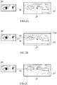
- FIG.2A to FIG.2C are schematic diagrams showing an image stabilization procedure in an embodiment.
- the first display image is displayed on the display 111 and the relative position between the viewer 201 and the display 111 is a first position that is represented by a dashed line R1. That is, one end of the dashed line R1 is aligned with eyes of the viewer 201 and the other end of the dashed line R1 is aligned with a locating point LP in the first display image. At the time, the locating point LP is located at an original position in the first display image.
- the processor 114 detects a visual dislocation event.
- the visual dislocation event refers to that the relative position between the viewer 201 and the display 111 changes from the first position to a second position represented by the dashed line R2.
- one end of the dashed line R2 is also aligned with the eyes of the viewer 201, but the other end of the dashed line R2 moves upward by a distance D1relative to the dashed line R1. That is, the visual dislocation event is considered as the upward movement of the viewer 201 relative to the display 111 by a distance D1 (or the downward movement of the display 111 relative to the viewer 201by the distance D1).
- an image stabilization procedure is performed by the processor 114 to reduce the impact of the visual dislocation event on the viewer.
- the processor 114 is configured to synchronously move the image displayed by the display 111 upward by a distance D2. That is, the image displayed by the display 111 is adjusted to the second display image via the image stabilization procedure.
- the second display image is displayed by the display 111.
- the locating point LP in the second display image is also shifted upward by the distance D2 relative to the locating point LP in the first display image to be align with the eyes of the viewer 201. That is, with the image stabilization procedure, even if a visual dislocation event occurs, the locating point LP is kept in alignment with the gazing direction of the viewer 201.
- the shifting direction of the image displayed by the display 111 is consistent with the shifting direction of the relative position between the viewer 201 and the display 111.
- the display 111 moves upward or downward relative to the viewer 201. Therefore, in the image stabilization procedure, the image displayed on the display 111 also moves upward or downward relative to the viewer 201 correspondingly.
- the movement of the display 111 relative to the viewer 201 is considered as the movement of the display 111 in a y-axis direction. Then, in the image stabilization procedure, the image displayed on the display 111 also moves in the y-axis direction of the display 111.
- the display 111 moves downward (that is, the display 111 moves in a negative y-axis direction) relative to the viewer 201 due to a visual dislocation event, the image displayed on the display 111 moves upward (that is, the image moves in a positive y-axis direction) relative to the viewer 201 in the image stabilization procedure, as shown in FIG.2B .
- the image displayed on the display 111 moves downward relative to the viewer 201 in the image stabilization procedure (that is, the image moves in the negative y-axis direction).
- the processor 114 determines the shifting distance D2 (that is, the offset distance) of the image displayed on the display 111 according to the detecting signal.
- the distance D2 is positively correlated to the magnitude of the change in the relative position between the viewer 201 and the display 111.
- the magnitude of the change in the relative position between the viewer 201 and the display 111 is represented by the distance D1, and the distance D2 is equal to the distance D1.
- the distance D2 is approximate to (a little greater or less than) the distance D1.
- the first display image is displayed by the display 111.
- the second display image is displayed by the display 111.
- one visual dislocation event corresponds to one shaking or wobbling. The visual dislocation event usually lasts for a little while.
- the visual dislocation event occurs, the relative position between the viewer 201 and the display 111 changes from the first position to the second position. Then, when the visual dislocation event is over, the relative position between the viewer 201 and the display 111 changes from the second position back to the first position.
- the processor 114 restores the image displayed by the display 111 to the first display image synchronously.
- the relative position between the viewer 201 and the image (or the locating point in the image) displayed by the display 111 is kept constant or only slightly changed.
- the image displayed on the display 111 is moved upward/downward to keep the relative position between the viewer 201 and the image displayed on the display 111 unchanged via the image stabilization procedure.
- the relative position between the viewer 201 and the image (or the locating point in the image) displayed by the display 111 is kept constant or only slightly changed by taking images in different regions of the original image.
- the processor 114 extracts the image in a region 310 of the original image 301 as the first display image.
- the first display image is displayed by the display 111.
- the region 310 has the same size as the display area (screen) of the display 11.
- the processor 114 determines the shifting direction (that is, the offset direction) of the image (or the locating point in the image) and the shifting distance (that is, the offset distance) according to the detecting signal to position the region 320 in the original image 301.
- the region 320 and the region 310 have the same size.
- the region 320 is shifted in the offset direction by the offset distance (such as, the offset distance D2 in the negative y-axis direction) relative to the region 310.
- the processor 114 extracts the image in the region 320 from the original image 301 as the second display image.
- the second display image is displayed by the display 111.
- the processor 114 extracts the image in the region 310 from the original image 301 as the first display image.
- the first display image is displayed by the display 111 again.
- the original image 301 is a dynamic or static image that is continuously played. Therefore, the images that are extracted from the region 310 and the region 320 of the original image 301 are also dynamic or static images continuously played.
- the image stabilization procedure includes multiple adjustments onto the images displayed on the display 111 accordingly.
- the image stabilization procedure is not performed if the forthcoming or current visual dislocation event is not detected. In an embodiment" , since the relative position between the viewer and the display does not change when the viewer and the display 111 move synchronously, the image stabilization procedure is not performed.
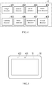
- FIG.4 is a block diagram showing a detector in an embodiment. Please refer to FIG.4 .
- the detector 12 includes at least one of an image detector 401, a motion detector 402, a speed detector 403, a travel route detector 404, a roadway detector 405, a brake detector 406, a horsepower detector 407 and a motion detector 408.
- the number of any of the image detector 401, the motion detector 402, the speed detector 403, the travel route detector 404, the roadway detector 405, the brake detector 406, the horsepower detector 407 and the motion detector 408 is one or more.
- the image detector 401 and/or the motion detector 402 are configured at the display 111 or the electronic device 111 with the display 111.
- the image detector 401 is configured to detect face image information of the viewer.
- the image detector 401 includes at least one lens.
- the image detector 401 is a face image detector.
- the motion detector 402 is configured to detect movement information of the display 111.
- the motion detector 402 includes at least one of an accelerometer sensor, a magnetic sensor, a gyro-sensor and a g-sensor, which is not limited herein.
- the motion detector 402 is also called as a display motion detector.
- the movement information includes information about the shaking/wobbling frequency, direction, and/or shaking/wobbling magnitude of the display 111.
- FIG.5 is a schematic diagram showing a display device in an embodiment. Please refer to FIG.5 .
- the image detector 401 is disposed at a side portion of a screen 51 of the display 111.
- the image detector 401 is capable of capturing the face image of the viewer in front of the display 111 and outputting a corresponding detecting signal.
- the processor 114 obtains facial feature information, such as eyeball position(s) and/or pupil size of the viewer according to the detecting signal output by the image detector 401.
- the processor 114 analyses the detecting signal output by the image detector 401 to determine whether a visual dislocation event occurs. In an embodiment, when the processor 114 determines that the eyeball position(s) of the viewer changes, it means that the visual dislocation event occurs.
- the processor 114 analyses the detecting signal output by the image detector 401 to determine parameters used for adjusting the image in the image stabilization procedure.
- the motion detector 402 is disposed at the display 111 or disposed inside the electronic apparatus 11 which includes the display 111. Thus, the motion detector 402 detects the wobbling or shaking of the display 111 and outputs a corresponding detecting signal.
- the processor 114 analyses the detecting signal output by the image detector 402 to determine whether a visual dislocation event occurs or determine parameters used for adjusting the image in the corresponding image stabilization procedure.
- the speed detector 403, the travel route detector 404, the roadway detector 405, the brake detector 406, the horsepower detector 407 or the motion detector 408 is disposed on a vehicle to detect the environmental information of the display 111.
- the speed detector 403 is configured to detect the speed information of the vehicle.
- the travel route detector 404 is configured to detect the route information of the vehicle.
- the roadway detector 405 is configured to detect the road condition information.
- the brake detector 406 is configured to detect the brake information.
- the horsepower detector 407 is configured to detect the horsepower information.
- the motion detector 408 is configured to detect the movement information of the vehicle.
- At least one of the speed detector 403 and the travel route detector 404 is connected to a navigation system of the vehicle. At least one of the speed information and the route information is provided by the navigation system.
- the roadway detector 405 includes at least one of a road image detector, an infrared ray detector, an ultrasonic transceiver, a millimeter radar and a laser detector.
- the road condition information includes at least one of the road image information of the road ahead and the obstacle information of the road ahead, which is not limited herein.
- the brake detector 406 and the horsepower detector 407 are connected to a powertrain system of the vehicle.
- the motion detector is connected to at least one of a tire and a shock-absorber of the vehicle.
- FIG.6 is a schematic diagram showing a vehicle in an embodiment. Please refer to FIG.6 .
- the speed detector 403 or the travel route detector 404 is integrated in a navigation device 601 of a vehicle.
- the navigation device 601 is configured to execute a navigation system.
- the speed detector 403 detects the current speed information of the vehicle 60
- the travel route detector 404 detects the route information related to the navigation route ahead of the vehicle 60 in the navigation information.
- the processor 114 obtains useful information about the speed, the direction, the time point of turning/changing lanes, the tilt of the vehicle body in turning.
- the roadway detector 405 is disposed at the front of the vehicle 60. In an embodiment, the roadway detector 405 is the road image detector 603 disposed inside the vehicle 60. In an embodiment, the road image detector 603 is a traveling data recorder. The roadway detector 405 detects the road image information or the obstacle information ahead of the vehicle 60. In an embodiment, the roadway detector 405 detects the road condition ahead of the vehicle 60 and outputs a corresponding detecting signal.
- the processor 114 obtains the information about the road condition (for example, whether there are bumps or hollows on the road ahead) ahead of the vehicle 60, the states of the traffic signals, the distance between the vehicle 60 and the front vehicle, the distance between the front obstacle and the vehicle 60 or the time point when the vehicle 60 hits the obstacle, which is not limited herein.
- the powertrain system of the vehicle 60 is shown via a dashed box 61.
- the powertrain system includes a brake unit (not shown) and an engine unit (not shown).
- the brake unit is configured to take a brake the vehicle 60.
- the engine unit is configured to drive the vehicle 60 to go forward or backward.
- the brake detector 406 is connected to the brake unit of the vehicle 60 to detect instant brakes of the vehicle 60.
- the horsepower detector 407 is connected to the engine unit of the vehicle 60 to detect instant changes of the horsepower of the vehicle 60, such as, a rotational speed. According to the detecting signal output by the brake detector 406, the processor 114 obtains the brake information of the vehicle 60. According to the detecting signal output by the horsepower detector 407, the processor 114 obtains the horsepower information of the vehicle 60.
- the speed detector 403 is connected to the powertrain system of the vehicle 60 to detect the speed of the vehicle 60.
- the motion detector 408 includes an accelerometer sensor, a magnetic sensor, a gyro-sensor, a g-sensor or a pressure sensor, which is not limited herein.
- the motion detector 402 is also called as a vehicle motion detector.
- the motion detector 408 is disposed at or connected to at least one of the front wheel 62 of the vehicle 60 and the shock-absorber inside the vehicle 60. In such a way, the detecting signal output from the motion detector 408 immediately reflects whether the vehicle 60 is in shaking or wobbling, as well as the direction, magnitude, and frequency of the shaking or wobbling.
- the motion detector 408 is disposed at the rear wheel 63 or at any position of the vehicle 60.
- the processor 114 detects whether a visual dislocation event occurs and/or determines parameters used for adjusting the images in the image stabilization procedure according to the detecting signals output from some of or all of the detectors that are disposed on the vehicle 60. In an embodiment, the processor 114 determines whether a visual dislocation event occurs, the time point of occurrence of the visual dislocation event, the changes of direction and/or magnitude in the relative position between the viewer and the display 111 on the vehicle 60 when the visual dislocation event occurs, and the offset direction and the offset distance of the image (or the locating point in the image) in the image stabilization procedure according to the speed information, the route information, the road condition information, the brake information, the horsepower information or the movement information of the moving vehicle 60.
- the processor 114 analyses the detecting signals output by the detectors disposed on the display 111 and the detectors disposed the vehicle 60, to detect whether a visual dislocation event occurs and determine parameters used for adjusting the image in the image stabilization procedure.
- the adjustment of the images in the image stabilization procedure includes the adjustment on the image resolution, the image projection distance and/or the image size (enlargement/reduction), which is not limited herein and depends on the requirement.
- the resolution of at least partial of the images that are displayed by the display 111 is reduced.
- the shifting direction of the image (or the locating point in the image) is various with the condition that the relative position between the viewer and the image displayed on the display 111 is kept unchanged.
- FIG.7 is a schematic diagram showing an electronic device in an embodiment. Please refer to FIG.7 .
- an electronic device 11 is a head-mounted display device 71, such as a virtual reality glass, an augmented reality glass and a smart mixed-reality glass.
- the head-mounted display device 71 at least includes the display 111, the connection interface 112, the memory 113, and the processor 114 mentioned in the embodiment of FIG.1 .
- the processor 111 of the head-mounted display device 71 receives the detecting signals from one or more of the detectors that are configured at the head-mounted display device 71 or on the vehicle 60 in FIG.6 wiredly or wirelessly.
- the processor 114 of the head-mounted display device 71 has a wireless connection with at least one detector that is configured on the vehicle 60 via the connection interface 112 to receive the detecting signal from the paired detector based on the wireless transmission 701.
- the processor 114 of the head-mounted display device 71 has a wired connection with at least one detector that is configured on the vehicle 60 via the connection interface 112 to receive the detecting signal from the paired detector based on the wired transmission. Then, the processor 114 of the head-mounted display device 71 analyses the received detecting signals to perform the image stabilization procedure. Related descriptions are mentioned above, which is not repeated here.
- the electronic device 11 is a head-mounted display device.
- the electronic device 11 is other mobile display devices, such as a vehicle-mounted display, a smart dashboard, a navigation device, a smart phone, a tablet computer, and a notebook computer, which is not limited herein.
- the electronic device 11 in FIG.1 is implemented in combination with the vehicle (such as, the vehicle 60).
- the images are displayed by the head-mounted display device 71 via the display 111.
- the processor 114 is configured at the head-mounted display device 71 or configured on the vehicle 60.
- the head-mounted display device 71 is replaced by a display (such as a vehicle-mounted display) movably or fixed to the vehicle.
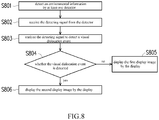
- FIG.8 is a flowchart of an image stabilization method in an embodiment. Please refer to FIG.8 .
- step S801 at least one detector detects environmental information and output a corresponding detecting signal.
- step S802 the detecting signal is received from the detector.
- step S803 the detecting signal is analyzed to detect a visual dislocation event.
- step S804 whether the visual dislocation event is detected is determined. If the visual dislocation event is not detected, in step S805, the first display image is displayed by the display. If the visual dislocation event is detected, in step S806, the image stabilization procedure is performed and the second display image is displayed by the display. The locating point in the second display image is shifted by an offset distance in an offset direction relative to the locating point in the first display image.
- the relative position between the viewer and the image displayed on the display 111 is kept constant or only slightly changed during the occurrence of the visual dislocation event.
- the step S801 is repeated.
- FIG.9 is a flowchart of an image stabilization method in an embodiment. Please refer to FIG.9 .
- step S901 whether a visual dislocation event is detected is determined. If the visual dislocation event is not detected, the image extracting region is a first region in the original image.
- step S902 the image in the first region is extracted from the original image as the first display image, and the first display image is displayed by the display. If the visual dislocation event is detected, the image extracting region is changed to a second region of the original image from the first region of the original image.
- the second region is positioned in the original image according to the detecting signal. The second region is shifted by an offset distance in an offset direction relative to the first region.
- step S904 the image in the second region is extracted from the original image as the second display image and the second display image is displayed by the display.
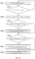
- FIG.10 is a flowchart of an image stabilization method in an embodiment. Please refer to FIG.10 .
- a detecting signal is received from the detector which is configured at the display.
- step S1002 whether the display is motionless is determined. If the display does not move, it is determined that the visual dislocation event does not occur, then back to step S1001. If the display moves, it indicates that the visual dislocation event may occur, and then go to step S1003.
- step S1003 the shaking magnitude, frequency or direction of the display is calculated.
- step S1004 whether the relative position between the eyeball position of the viewer and the display changes is determined.
- step S1005 If the relative position between the eyeball position of the viewer and the display changes, in step S1005, a change value of the relative position between the eyeball position of viewer and the display is calculated. If the relative position between the eyeball position of the viewer and the display does not change, then go to step S1006. In step S1006, whether a detecting signal is received from the detector that is configured on the vehicle is determined. In an embodiment, whether a preset detecting signal is received instantly from the navigation system, the powertrain system, the suspension system or the traveling data recorder of the vehicle is determined.
- step S1007 the magnitude, the frequency or the tilt angle of the current or forthcoming shaking of the vehicle is calculated. If the preset detecting signal is not received instantly from the navigation system, the powertrain system, the suspension system or the traveling data recorder of the vehicle, then go to step S1008. In step S1008, the image stabilization procedure is performed according to the calculated data information.
- FIG.8 to FIG.10 Details for the steps in FIG.8 to FIG.10 are described above.
- the steps in FIG.8 to FIG.10 are implemented by a plurality of program codes or circuits, which is not limited herein.
- a plurality of software modules are configured in the memory 113.
- the processor 114 reads and loads the software modules from the memory 113, the processor 114 performs the various functions mentioned above.
- the processor 114 includes a plurality of hardware circuits that are configured to perform the various functions mentioned above.
- the hardware circuits includes a signal-analyzing circuit configured to analyze the detecting signal to detect the visual dislocation event, an image-adjusting circuit configured to adjust the display images and an image-providing circuit configured to provide the display image for the display to display, which is not limited herein.
- the method in embodiments of FIG.8 to FIG.10 can be used in combination or separately, which is not limited herein.
- the detectors are used for detecting the environmental information.
- the forthcoming or current visual dislocation event is detected according to the detecting signals output from the detectors, and the image stabilization procedure is performed accordingly.
- the visual dislocation event refers to that the relative position between the viewer and the display changes.
- the image stabilization procedure the image displayed by the display is adjusted to keep the relative position between the viewer and the image displayed on the display unchanged. Thus, users would not feel so uncomfortable in viewing the image when the user's body or the display shakes.
Landscapes
- Engineering & Computer Science (AREA)
- Chemical & Material Sciences (AREA)
- Mechanical Engineering (AREA)
- Transportation (AREA)
- Combustion & Propulsion (AREA)
- Physics & Mathematics (AREA)
- General Physics & Mathematics (AREA)
- Theoretical Computer Science (AREA)
- Computer Hardware Design (AREA)
- Signal Processing (AREA)
- Multimedia (AREA)
- Optics & Photonics (AREA)
- Controls And Circuits For Display Device (AREA)
Abstract
Description
- The disclosure relates to an image stabilization technology and, more specifically, to an image stabilization method and an electronic device using the image stabilization method.
- With the popularity of mobile display devices, the mobile display devices are used anytime, anywhere, even on a moving vehicle. However, the moving vehicle is under an unstable circumstance, the user does not easy to focus on the display. Consequently, eyes easily get tired. Moreover, dizzy or even high intraocular pressure occurs. If the user wears a head-mounted display on a vehicle, the uncomfortable feelings for a user may be worse.
- According to an aspect of the invention, an image stabilization method adapted to an electronic device is provided. The electronic device includes at least a display and at least a connection interface. The connection interface is connected to the detector. The detector is used for detecting environmental information. The image stabilization method comprises: receiving a detecting signal from the detector; and performing an image stabilization procedure corresponding to a visual dislocation event according to the detecting signal. The visual dislocation event refers to a change of a relative position between the viewer and the display from a first position to a second position. The image stabilization procedure includes: changing an image extracting region from a first region of an original image to a second region of the original image according to the detecting signal; and displaying a second display image in the second region on the display. The second region is shifted by an offset distance in an offset direction relative to the first region.
- According to another aspect of the invention, an electronic device comprises: a display; at least a connection interface for being connected with at least a detector; and a processor coupled to the display and the connection interface. The detector is configured for detecting environmental information. The processor is configured to receive a detecting signal from the detector and perform an image stabilization procedure corresponding to a visual dislocation event according to the detecting signal. The visual dislocation event refers to a change of a relative position between the viewer and the display from a first position to a second position. In the image stabilization procedure, an image displayed by the display is adjusted from a first display image in a first region of an original image to a second display image in a second region of the original image. A locating point in the second display image is shifted by an offset distance in an offset direction relative to the locating point in the first display image.
- In sum, in embodiments of the disclosure, the detector is used for detecting the environmental information. The image stabilization procedure corresponding to the visual dislocation event is performed according to the detecting signal output from the detector. The visual dislocation event refers to a change of the relative position between the user and the display. In the image stabilization procedure, the image displayed on the display is automatically adjusted by shifting one locating point in the image by an offset distance in the offset direction. Thus, users would not feel so uncomfortable in viewing the image when the user's body or the display shakes.
- These and other features, aspects and advantages of the disclosure will become better understood with regard to the following embodiments and accompanying drawings.
-
FIG.1 is a schematic diagram showing an image stabilization system in an embodiment; -
FIG.2A to FIG.2C are schematic diagrams showing an image stabilization procedure in an embodiment; -
FIG.3A to FIG.3C are schematic diagrams showing an image stabilization procedure in an embodiment; -
FIG.4 is a block diagram showing a detector in an embodiment; -
FIG.5 is a schematic diagram showing a display in an embodiment; -
FIG.6 is a schematic diagram showing a vehicle in an embodiment; -
FIG.7 is a schematic diagram showing an electronic device in an embodiment; -
FIG.8 is a flowchart of an image stabilization method in an embodiment; -
FIG.9 is a flowchart of an image stabilization method in an embodiment; and -
FIG.10 is a flowchart of an image stabilization method in an embodiment. -
FIG.1 is a schematic diagram showing an image stabilization system in an embodiment. - Please refer to
FIG.1 . Animage stabilization system 10 includes anelectronic device 11 and adetector 12. Theelectronic device 11 includes adisplay 111, aconnection interface 112, amemory 113, and aprocessor 114. In the embodiment, thedisplay 111 is, but not limited to, a liquid crystal display (LCD), a light-emitting diode (LED) display, an organic light emitting display (OLED), or an electrophoretic display (EPD). - The
connection interface 112 is connected to thedetector 12. The number of theconnection interfaces 112 is one or more. When the number of theconnection interface 112 is more than one, the type of theconnection interfaces 112 is the same or various to each other. Theconnection interface 112 includes a wired and/or wireless and supports wired and/or wireless communication standards, respectively. - In an embodiment, the
connection interface 112 includes at least a wired connection interface. Theconnection interface 112 supports the inter-integrated circuit bus (I2C bus) standard, the standard mobile imaging architecture (SMIA) standard, the mobile video interface (MPL) standard, the mobile video interface (MVI) standard, the mobile display digital interface (MDDI) standard, the peripheral component interconnect express (PCI Express) standard or the universal serial bus (USB) standard, which is not limited herein. - In an embodiment, the
connection interface 112 includes at least a wireless connection interface. Theconnection interface 112 supports a global system for mobile communication (GSM) system, a personal handy-phone system (PHS), a code division multiple access (CDMA) system, a wireless fidelity (Wi-Fi) system, a worldwide interoperability for microwave access (WiMAX) system, a long term evolution (LTE) system, a near field communication (NFC) system or a blue-tooth system, which is not limited herein. In an embodiment, the wireless connection interface includes various communication circuits (such as an antenna circuit and a high-frequency circuit) to perform the wireless communication function. - In an embodiment, the
memory 113 is any type of a fixed or removable random access memory (RAM), a read-only memory (ROM), or a flash memory, which is not limited herein. In an embodiment, thememory 113 includes other types of storage media. - The
processor 114 is coupled to thedisplay 111, theconnection interface 112, and thememory 113. In an embodiment, theprocessor 114 is a single-core or multi-core central processing unit (CPU). In an embodiment, theprocessor 114 is other programmable microprocessor in general /special purpose, a digital signal processor (DSP), a programmable controller, an application specific integrated circuit (ASIC) or an embedded controller, which is not limited herein. - The
detector 12 is configured to detect environmental information and output a detecting signal accordingly. The number ofdetectors 12 is one or more. The type of thedetectors 12 is the same or various. In the embodiment, thedetector 12 is external to theelectronic device 11. However, in an embodiment, thedetector 12 is a component of theelectronic device 11. - In the embodiment, the
processor 114 controls thedisplay 111 to display an image. In embodiments, the image is a text, a symbol, a movie, or a picture. In an embodiment, the content of the image is stored in thememory 113. The image is played by thedisplay 111 after applying an image processing procedure (such as decoding) to the image by theprocessor 114. Theprocessor 114 receives a detecting signal from thedetector 12 via theconnection interface 112. At a particular time point, an image stabilization procedure corresponding to a visual dislocation event is performed by theprocessor 114 based on the detecting signal. In an embodiment, theprocessor 114 analyzes the environmental information detected by thedetector 12 according to the detecting signal, and detects the visual dislocation event according to the analysis result of the environmental information. When a forthcoming or current visual dislocation event is detected, the corresponding image stabilization procedure is performed by theprocessor 114 immediately. - In the embodiment, the visual dislocation event refers to the change of the relative position between the viewer and the
display 111. In an embodiment, when the viewer views a first display image on thedisplay 111 in front of thedisplay 111 and, the relative position between the viewer and thedisplay 111 changes from a first position to a second position according to the movement of the viewer or thedisplay 111. In an embodiment, when the relative position between the viewer and thedisplay 111 is changing, the viewer feels that thedisplay 111 is moved upward, downward, left, right, or in other direction relative to him or her. That is, when the visual dislocation event occurs, the viewer may feel that only thedisplay 111 is moved. - Generally, the visual dislocation event is caused by a sudden shaking or wobbling of the viewer or the
display 111. In an embodiment, the visual dislocation event is caused by different shaking (wobbling) frequencies, directions and/or magnitudes between the viewer and thedisplay 111. The shaking or wobbling is not expected or controlled by the viewer. In an embodiment, on a moving vehicle (such as an automobile, a train, an airplane, and a MRT), the viewer or thedisplay 111 shakes with the movement of the vehicle. In an embodiment, when the viewer is walking and using theelectronic device 10, the viewer or thedisplay 111 of theelectronic device 10 shakes with the paces of the viewer. - When the visual dislocation event occurs, the viewer's eyes needs to move with the shaking or wobbling
display 111 due to the change of the relative position between the viewer and thedisplay 111. Therefore, if the visual dislocation events occur frequently, the viewer need to pay much attention to view the image displayed on thedisplay 111. As a result, the viewer may feel dizzy or have a high intraocular pressure. - In the embodiment, when a forthcoming or current visual dislocation event is detected, the
processor 114 adaptively adjusts the image displayed on thedisplay 111 via the image stabilization procedure. In an embodiment, in the image stabilization procedure, theprocessor 114 adjusts the image displayed on thedisplay 111 from first display image to a second display image. A locating point in the second display image is shifted by an offset distance in an offset direction relative to the locating point in the first display image. That is, when the viewer or thedisplay 111 has a sudden shaking or wobbling, the image displayed on thedisplay 111 is shifted by the offset distance in the offset direction to prevent great changes of the relative position between the viewer and the image displayed on thedisplay 111. Therefore, even if the visual dislocation event occurs, the relative position between the viewer and the image displayed on thedisplay 111 is kept constant or only slightly changed. Consequently, the viewer's eyes do not need to move with the shaking/vibratingdisplay 111, which makes the viewer feel more comfortable. -
FIG.2A to FIG.2C are schematic diagrams showing an image stabilization procedure in an embodiment. - Please refer to
FIG.2A . In an embodiment, it is assumed that the first display image is displayed on thedisplay 111 and the relative position between theviewer 201 and thedisplay 111 is a first position that is represented by a dashed line R1. That is, one end of the dashed line R1 is aligned with eyes of theviewer 201 and the other end of the dashed line R1 is aligned with a locating point LP in the first display image. At the time, the locating point LP is located at an original position in the first display image. - Please refer to
FIG.2B . Theprocessor 114 detects a visual dislocation event. The visual dislocation event refers to that the relative position between theviewer 201 and thedisplay 111 changes from the first position to a second position represented by the dashed line R2. In the embodiment, one end of the dashed line R2 is also aligned with the eyes of theviewer 201, but the other end of the dashed line R2 moves upward by a distance D1relative to the dashed line R1. That is, the visual dislocation event is considered as the upward movement of theviewer 201 relative to thedisplay 111 by a distance D1 (or the downward movement of thedisplay 111 relative to the viewer 201by the distance D1). Thus, an image stabilization procedure is performed by theprocessor 114 to reduce the impact of the visual dislocation event on the viewer. In an embodiment, when theviewer 201 moves upward by the distance D1 relative to thedisplay 111, theprocessor 114 is configured to synchronously move the image displayed by thedisplay 111 upward by a distance D2. That is, the image displayed by thedisplay 111 is adjusted to the second display image via the image stabilization procedure. - Please refer to
FIG2C , when the visual dislocation event is detected, the second display image is displayed by thedisplay 111. The locating point LP in the second display image is also shifted upward by the distance D2 relative to the locating point LP in the first display image to be align with the eyes of theviewer 201. That is, with the image stabilization procedure, even if a visual dislocation event occurs, the locating point LP is kept in alignment with the gazing direction of theviewer 201. - In the embodiment, the shifting direction of the image displayed by the
display 111 is consistent with the shifting direction of the relative position between theviewer 201 and thedisplay 111. In an embodiment, as shown inFIG.2A to FIG.2C , when the visual dislocation event occurs, thedisplay 111 moves upward or downward relative to theviewer 201. Therefore, in the image stabilization procedure, the image displayed on thedisplay 111 also moves upward or downward relative to theviewer 201 correspondingly. In an embodiment, the movement of thedisplay 111 relative to theviewer 201 is considered as the movement of thedisplay 111 in a y-axis direction. Then, in the image stabilization procedure, the image displayed on thedisplay 111 also moves in the y-axis direction of thedisplay 111. In an embodiment, thedisplay 111 moves downward (that is, thedisplay 111 moves in a negative y-axis direction) relative to theviewer 201 due to a visual dislocation event, the image displayed on thedisplay 111 moves upward (that is, the image moves in a positive y-axis direction) relative to theviewer 201 in the image stabilization procedure, as shown inFIG.2B . In an embodiment, when thedisplay 111 moves upward (that is, thedisplay 111 moves in the positive y-axis direction) relative to theviewer 201 due to the visual dislocation event, the image displayed on thedisplay 111 moves downward relative to theviewer 201 in the image stabilization procedure (that is, the image moves in the negative y-axis direction). - In the embodiment, the
processor 114 determines the shifting distance D2 (that is, the offset distance) of the image displayed on thedisplay 111 according to the detecting signal. The distance D2 is positively correlated to the magnitude of the change in the relative position between theviewer 201 and thedisplay 111. In the embodiment, the magnitude of the change in the relative position between theviewer 201 and thedisplay 111 is represented by the distance D1, and the distance D2 is equal to the distance D1. However, in an embodiment, the distance D2 is approximate to (a little greater or less than) the distance D1. - In the embodiment, when the relative position between the
viewer 201 and thedisplay 111 is in the first position, the first display image is displayed by thedisplay 111. When the relative position between theviewer 201 and thedisplay 111 is in the second position, the second display image is displayed by thedisplay 111. In an embodiment, one visual dislocation event corresponds to one shaking or wobbling. The visual dislocation event usually lasts for a little while. When the visual dislocation event occurs, the relative position between theviewer 201 and thedisplay 111 changes from the first position to the second position. Then, when the visual dislocation event is over, the relative position between theviewer 201 and thedisplay 111 changes from the second position back to the first position. - In other words, when the relative position between the
viewer 201 and thedisplay 111 changes from the second position to the first position. Theprocessor 114 restores the image displayed by thedisplay 111 to the first display image synchronously. Thus, during the occurrence of the visual dislocation event, even if the relative position between theviewer 201 and thedisplay 111 changes continuously, the relative position between theviewer 201 and the image (or the locating point in the image) displayed by thedisplay 111 is kept constant or only slightly changed. - In
FIG.2A to FIG.2C , in the embodiment, the image displayed on thedisplay 111 is moved upward/downward to keep the relative position between theviewer 201 and the image displayed on thedisplay 111 unchanged via the image stabilization procedure. In other embodiment, the relative position between theviewer 201 and the image (or the locating point in the image) displayed by thedisplay 111 is kept constant or only slightly changed by taking images in different regions of the original image. - Please refer to
FIG.2A andFIG.3A , before the image stabilization procedure is performed (or the visual dislocation event is detected), theprocessor 114 extracts the image in aregion 310 of theoriginal image 301 as the first display image. The first display image is displayed by thedisplay 111. In an embodiment, theregion 310 has the same size as the display area (screen) of thedisplay 11. After the visual dislocation event shown inFIG.2B is detected, the image stabilization procedure is performed by theprocessor 114. - Please refer to
FIG.2B andFIG.3B , in the image stabilization procedure, theprocessor 114 determines the shifting direction (that is, the offset direction) of the image (or the locating point in the image) and the shifting distance (that is, the offset distance) according to the detecting signal to position theregion 320 in theoriginal image 301. Theregion 320 and theregion 310 have the same size. Theregion 320 is shifted in the offset direction by the offset distance (such as, the offset distance D2 in the negative y-axis direction) relative to theregion 310. - Please refer to
FIG.2C andFIG.3C . After theregion 320 is positioned, theprocessor 114 extracts the image in theregion 320 from theoriginal image 301 as the second display image. The second display image is displayed by thedisplay 111. After the end of the visual dislocation event, theprocessor 114 extracts the image in theregion 310 from theoriginal image 301 as the first display image. The first display image is displayed by thedisplay 111 again. - In an embodiment, the
original image 301 is a dynamic or static image that is continuously played. Therefore, the images that are extracted from theregion 310 and theregion 320 of theoriginal image 301 are also dynamic or static images continuously played. - For multiple visual dislocation events, the change of the relative position between the
viewer 201 and thedisplay 111 is considered as consecutively changes. The image stabilization procedure includes multiple adjustments onto the images displayed on thedisplay 111 accordingly. - In an embodiment, the image stabilization procedure is not performed if the forthcoming or current visual dislocation event is not detected. In an embodiment" , since the relative position between the viewer and the display does not change when the viewer and the
display 111 move synchronously, the image stabilization procedure is not performed. -
FIG.4 is a block diagram showing a detector in an embodiment. Please refer toFIG.4 . Thedetector 12 includes at least one of animage detector 401, amotion detector 402, aspeed detector 403, atravel route detector 404, aroadway detector 405, abrake detector 406, ahorsepower detector 407 and amotion detector 408. In an embodiment, the number of any of theimage detector 401, themotion detector 402, thespeed detector 403, thetravel route detector 404, theroadway detector 405, thebrake detector 406, thehorsepower detector 407 and themotion detector 408 is one or more. - In an embodiment, the
image detector 401 and/or themotion detector 402 are configured at thedisplay 111 or theelectronic device 111 with thedisplay 111. Theimage detector 401 is configured to detect face image information of the viewer. In an embodiment, theimage detector 401 includes at least one lens. In an embodiment, theimage detector 401 is a face image detector. Themotion detector 402 is configured to detect movement information of thedisplay 111. In an embodiment, themotion detector 402 includes at least one of an accelerometer sensor, a magnetic sensor, a gyro-sensor and a g-sensor, which is not limited herein. In an embodiment, themotion detector 402 is also called as a display motion detector. In an embodiment, the movement information includes information about the shaking/wobbling frequency, direction, and/or shaking/wobbling magnitude of thedisplay 111. -
FIG.5 is a schematic diagram showing a display device in an embodiment. Please refer toFIG.5 . Theimage detector 401 is disposed at a side portion of ascreen 51 of thedisplay 111. Thus, theimage detector 401 is capable of capturing the face image of the viewer in front of thedisplay 111 and outputting a corresponding detecting signal. In an embodiment, theprocessor 114 obtains facial feature information, such as eyeball position(s) and/or pupil size of the viewer according to the detecting signal output by theimage detector 401. Theprocessor 114 analyses the detecting signal output by theimage detector 401 to determine whether a visual dislocation event occurs. In an embodiment, when theprocessor 114 determines that the eyeball position(s) of the viewer changes, it means that the visual dislocation event occurs. In an embodiment, theprocessor 114 analyses the detecting signal output by theimage detector 401 to determine parameters used for adjusting the image in the image stabilization procedure. - The
motion detector 402 is disposed at thedisplay 111 or disposed inside theelectronic apparatus 11 which includes thedisplay 111. Thus, themotion detector 402 detects the wobbling or shaking of thedisplay 111 and outputs a corresponding detecting signal. Theprocessor 114 analyses the detecting signal output by theimage detector 402 to determine whether a visual dislocation event occurs or determine parameters used for adjusting the image in the corresponding image stabilization procedure. - Please refer to
FIG.4 . In an embodiment, thespeed detector 403, thetravel route detector 404, theroadway detector 405, thebrake detector 406, thehorsepower detector 407 or themotion detector 408 is disposed on a vehicle to detect the environmental information of thedisplay 111. Thespeed detector 403 is configured to detect the speed information of the vehicle. Thetravel route detector 404 is configured to detect the route information of the vehicle. Theroadway detector 405 is configured to detect the road condition information. Thebrake detector 406 is configured to detect the brake information. Thehorsepower detector 407 is configured to detect the horsepower information. Themotion detector 408 is configured to detect the movement information of the vehicle. - In an embodiment, at least one of the
speed detector 403 and thetravel route detector 404 is connected to a navigation system of the vehicle. At least one of the speed information and the route information is provided by the navigation system. In an embodiment, theroadway detector 405 includes at least one of a road image detector, an infrared ray detector, an ultrasonic transceiver, a millimeter radar and a laser detector. The road condition information includes at least one of the road image information of the road ahead and the obstacle information of the road ahead, which is not limited herein. In an embodiment, thebrake detector 406 and thehorsepower detector 407 are connected to a powertrain system of the vehicle. In an embodiment, the motion detector is connected to at least one of a tire and a shock-absorber of the vehicle. -
FIG.6 is a schematic diagram showing a vehicle in an embodiment. Please refer toFIG.6 . In an embodiment, thespeed detector 403 or thetravel route detector 404 is integrated in anavigation device 601 of a vehicle. Thenavigation device 601 is configured to execute a navigation system. According to navigation information from the navigation system, thespeed detector 403 detects the current speed information of thevehicle 60, and thetravel route detector 404 detects the route information related to the navigation route ahead of thevehicle 60 in the navigation information. According to the detecting signals output by thespeed detector 403 and thetravel route detector 404, theprocessor 114 obtains useful information about the speed, the direction, the time point of turning/changing lanes, the tilt of the vehicle body in turning. - In an embodiment, the
roadway detector 405 is disposed at the front of thevehicle 60. In an embodiment, theroadway detector 405 is theroad image detector 603 disposed inside thevehicle 60. In an embodiment, theroad image detector 603 is a traveling data recorder. Theroadway detector 405 detects the road image information or the obstacle information ahead of thevehicle 60. In an embodiment, theroadway detector 405 detects the road condition ahead of thevehicle 60 and outputs a corresponding detecting signal. According to the detecting signal of theroadway detector 405, theprocessor 114 obtains the information about the road condition (for example, whether there are bumps or hollows on the road ahead) ahead of thevehicle 60, the states of the traffic signals, the distance between thevehicle 60 and the front vehicle, the distance between the front obstacle and thevehicle 60 or the time point when thevehicle 60 hits the obstacle, which is not limited herein. - In
FIG.6 , the powertrain system of thevehicle 60 is shown via a dashedbox 61. In an embodiment, the powertrain system includes a brake unit (not shown) and an engine unit (not shown). The brake unit is configured to take a brake thevehicle 60. The engine unit is configured to drive thevehicle 60 to go forward or backward. In an embodiment, thebrake detector 406 is connected to the brake unit of thevehicle 60 to detect instant brakes of thevehicle 60. In an embodiment, thehorsepower detector 407 is connected to the engine unit of thevehicle 60 to detect instant changes of the horsepower of thevehicle 60, such as, a rotational speed. According to the detecting signal output by thebrake detector 406, theprocessor 114 obtains the brake information of thevehicle 60. According to the detecting signal output by thehorsepower detector 407, theprocessor 114 obtains the horsepower information of thevehicle 60. In an embodiment, thespeed detector 403 is connected to the powertrain system of thevehicle 60 to detect the speed of thevehicle 60. - In an embodiment, the
motion detector 408 includes an accelerometer sensor, a magnetic sensor, a gyro-sensor, a g-sensor or a pressure sensor, which is not limited herein. In an embodiment, themotion detector 402 is also called as a vehicle motion detector. In an embodiment, themotion detector 408 is disposed at or connected to at least one of thefront wheel 62 of thevehicle 60 and the shock-absorber inside thevehicle 60. In such a way, the detecting signal output from themotion detector 408 immediately reflects whether thevehicle 60 is in shaking or wobbling, as well as the direction, magnitude, and frequency of the shaking or wobbling. In embodiments, themotion detector 408 is disposed at therear wheel 63 or at any position of thevehicle 60. - In
FIG.6 , in the embodiment, theprocessor 114 detects whether a visual dislocation event occurs and/or determines parameters used for adjusting the images in the image stabilization procedure according to the detecting signals output from some of or all of the detectors that are disposed on thevehicle 60. In an embodiment, theprocessor 114 determines whether a visual dislocation event occurs, the time point of occurrence of the visual dislocation event, the changes of direction and/or magnitude in the relative position between the viewer and thedisplay 111 on thevehicle 60 when the visual dislocation event occurs, and the offset direction and the offset distance of the image (or the locating point in the image) in the image stabilization procedure according to the speed information, the route information, the road condition information, the brake information, the horsepower information or the movement information of the movingvehicle 60. In another embodiment inFIG.6 , theprocessor 114 analyses the detecting signals output by the detectors disposed on thedisplay 111 and the detectors disposed thevehicle 60, to detect whether a visual dislocation event occurs and determine parameters used for adjusting the image in the image stabilization procedure. - In an embodiment, the adjustment of the images in the image stabilization procedure includes the adjustment on the image resolution, the image projection distance and/or the image size (enlargement/reduction), which is not limited herein and depends on the requirement. In an embodiment, when the visual dislocation event occurs too frequently, the resolution of at least partial of the images that are displayed by the
display 111 is reduced. Thus, the burden on the viewer's eyes due to the too sharp of the images is relieved. In an embodiment, the shifting direction of the image (or the locating point in the image) is various with the condition that the relative position between the viewer and the image displayed on thedisplay 111 is kept unchanged. -
FIG.7 is a schematic diagram showing an electronic device in an embodiment. Please refer toFIG.7 . In an embodiment, anelectronic device 11 is a head-mounteddisplay device 71, such as a virtual reality glass, an augmented reality glass and a smart mixed-reality glass. The head-mounteddisplay device 71 at least includes thedisplay 111, theconnection interface 112, thememory 113, and theprocessor 114 mentioned in the embodiment ofFIG.1 . Theprocessor 111 of the head-mounteddisplay device 71 receives the detecting signals from one or more of the detectors that are configured at the head-mounteddisplay device 71 or on thevehicle 60 inFIG.6 wiredly or wirelessly. In an embodiment, theprocessor 114 of the head-mounteddisplay device 71 has a wireless connection with at least one detector that is configured on thevehicle 60 via theconnection interface 112 to receive the detecting signal from the paired detector based on thewireless transmission 701. In an embodiment, theprocessor 114 of the head-mounteddisplay device 71 has a wired connection with at least one detector that is configured on thevehicle 60 via theconnection interface 112 to receive the detecting signal from the paired detector based on the wired transmission. Then, theprocessor 114 of the head-mounteddisplay device 71 analyses the received detecting signals to perform the image stabilization procedure. Related descriptions are mentioned above, which is not repeated here. - In an embodiment, when a user wears the head-mounted
display device 71 to view the images displayed on thedisplay 111 of the head-mounteddisplay device 71 on the movingvehicle 60, with the image stabilization procedure, the discomfort feeling of the user caused by the shaking or wobbling of the movingvehicle 60 is reduced. In the embodiment inFIG.7 , theelectronic device 11 is a head-mounted display device. However, in embodiments, theelectronic device 11 is other mobile display devices, such as a vehicle-mounted display, a smart dashboard, a navigation device, a smart phone, a tablet computer, and a notebook computer, which is not limited herein. - In an embodiment, the
electronic device 11 inFIG.1 is implemented in combination with the vehicle (such as, the vehicle 60). In the embodiment ofFIG.6 and FIG.7 , the images are displayed by the head-mounteddisplay device 71 via thedisplay 111. In an embodiment, theprocessor 114 is configured at the head-mounteddisplay device 71 or configured on thevehicle 60. InFIG.7 , in an embodiment, the head-mounteddisplay device 71 is replaced by a display (such as a vehicle-mounted display) movably or fixed to the vehicle. -
FIG.8 is a flowchart of an image stabilization method in an embodiment. Please refer toFIG.8 . In step S801, at least one detector detects environmental information and output a corresponding detecting signal. In step S802, the detecting signal is received from the detector. In step S803, the detecting signal is analyzed to detect a visual dislocation event. In step S804, whether the visual dislocation event is detected is determined. If the visual dislocation event is not detected, in step S805, the first display image is displayed by the display. If the visual dislocation event is detected, in step S806, the image stabilization procedure is performed and the second display image is displayed by the display. The locating point in the second display image is shifted by an offset distance in an offset direction relative to the locating point in the first display image. Thus, with the image stabilization procedure, the relative position between the viewer and the image displayed on thedisplay 111 is kept constant or only slightly changed during the occurrence of the visual dislocation event. In an embodiment, after the steps S805 and S806, the step S801 is repeated. -
FIG.9 is a flowchart of an image stabilization method in an embodiment. Please refer toFIG.9 . In step S901, whether a visual dislocation event is detected is determined. If the visual dislocation event is not detected, the image extracting region is a first region in the original image. In step S902, the image in the first region is extracted from the original image as the first display image, and the first display image is displayed by the display. If the visual dislocation event is detected, the image extracting region is changed to a second region of the original image from the first region of the original image. In step S903, the second region is positioned in the original image according to the detecting signal. The second region is shifted by an offset distance in an offset direction relative to the first region. In step S904, the image in the second region is extracted from the original image as the second display image and the second display image is displayed by the display. -
FIG.10 is a flowchart of an image stabilization method in an embodiment. Please refer toFIG.10 . In step S1001, a detecting signal is received from the detector which is configured at the display. In step S1002, whether the display is motionless is determined. If the display does not move, it is determined that the visual dislocation event does not occur, then back to step S1001. If the display moves, it indicates that the visual dislocation event may occur, and then go to step S1003. In step S1003, the shaking magnitude, frequency or direction of the display is calculated. In step S1004, whether the relative position between the eyeball position of the viewer and the display changes is determined. If the relative position between the eyeball position of the viewer and the display changes, in step S1005, a change value of the relative position between the eyeball position of viewer and the display is calculated. If the relative position between the eyeball position of the viewer and the display does not change, then go to step S1006. In step S1006, whether a detecting signal is received from the detector that is configured on the vehicle is determined. In an embodiment, whether a preset detecting signal is received instantly from the navigation system, the powertrain system, the suspension system or the traveling data recorder of the vehicle is determined. If the preset detecting signal is received instantly from the navigation system, the powertrain system, the suspension system or the traveling data recorder of the vehicle, then, in step S1007, the magnitude, the frequency or the tilt angle of the current or forthcoming shaking of the vehicle is calculated. If the preset detecting signal is not received instantly from the navigation system, the powertrain system, the suspension system or the traveling data recorder of the vehicle, then go to step S1008. In step S1008, the image stabilization procedure is performed according to the calculated data information. - Details for the steps in
FIG.8 to FIG.10 are described above. The steps inFIG.8 to FIG.10 are implemented by a plurality of program codes or circuits, which is not limited herein. In an embodiment ofFIG.1 , a plurality of software modules are configured in thememory 113. When theprocessor 114 reads and loads the software modules from thememory 113, theprocessor 114 performs the various functions mentioned above. In another embodiment ofFIG.1 , theprocessor 114 includes a plurality of hardware circuits that are configured to perform the various functions mentioned above. In an embodiment, the hardware circuits includes a signal-analyzing circuit configured to analyze the detecting signal to detect the visual dislocation event, an image-adjusting circuit configured to adjust the display images and an image-providing circuit configured to provide the display image for the display to display, which is not limited herein. In an embodiment, the method in embodiments ofFIG.8 to FIG.10 can be used in combination or separately, which is not limited herein. - In sum, in embodiments, the detectors are used for detecting the environmental information. When the images are displayed by the display, the forthcoming or current visual dislocation event is detected according to the detecting signals output from the detectors, and the image stabilization procedure is performed accordingly. The visual dislocation event refers to that the relative position between the viewer and the display changes. In the image stabilization procedure, the image displayed by the display is adjusted to keep the relative position between the viewer and the image displayed on the display unchanged. Thus, users would not feel so uncomfortable in viewing the image when the user's body or the display shakes.
Claims (8)
- An image stabilization method, adapted to an electronic device (11, 71) including at least a display (111) and at least a connection interface (112), the connection interface (112) is connected to a detector (12, 401-408, 603) for detecting environmental information, the image stabilization method comprising:receiving (S802, S1001) a detecting signal from the detector (12, 401-408, 603); andperforming (S1008) an image stabilization procedure corresponding to a visual dislocation event according to the detecting signal, the visual dislocation event refers to a change of a relative position between the viewer (201) and the display (111) from a first position to a second position,wherein the image stabilization procedure includes:changing an image extracting region from a first region (310) of an original image (301) to a second region (320) of the original image (301) according to the detecting signal, the second region (320) is shifted by an offset distance (D2) in an offset direction relative to the first region (310); anddisplaying (S806) a second display image in the second region (320) on the display (111).
- The image stabilization method according to claim 1, wherein the offset direction is consistent with a direction in which the relative position changes.
- The image stabilization method according to claim 1, wherein the image stabilization procedure further comprises:determining the offset distance (D2) according to the detecting signal, wherein the offset distance (D2) is positively correlated to a magnitude of the change in the relative position.
- The image stabilization method according to claim 1, wherein the image stabilization procedure further comprises:establishing a wireless pairing or a wired connection with the detector (12, 401-408, 603) via the connection interface (112); andreceiving the detecting signal from the pair detector (12, 401-408, 603) via a wireless transmission (701) or receiving the detecting signal from the connected detector (12, 401-408, 603) via a wired transmission.
- An electronic device (11, 71) comprising:a display (111);at least a connection interface (112);a detector (12, 401-408, 603), connected to the connection interface (112) and configured to detect environmental information; anda processor (114), coupled to the display (111) and the connection interface (112), and configured to receive a detecting signal from the detector (12, 401-408, 603) and perform an image stabilization procedure corresponding to a visual dislocation event according to the detecting signal,wherein the visual dislocation event refers to a change of a relative position between the viewer (201) and the display (111) from a first position to a second position, and the image stabilization procedure comprises to adjust an image displayed by the display (111) from a first display image in a first region (310) of an original image (301) on the display (111) to a second display image in a second region (320) of the original image (301), and shift a locating point (LP) in the second display image by an offset distance (D2) in an offset direction relative to the locating point (LP) in the first display image.
- The electronic device according to claim 5, wherein the offset direction is consistent with a direction in which the relative position changes.
- The electronic device according to claim 5, wherein in the image stabilization procedure, the processor (114) is further configured to determine the offset distance (D2) according to the detecting signal, the offset distance (D2) is positively correlated to a magnitude of the change in the relative position.
- The electronic device according to claim 5, wherein the processor (114) is further configured to establish a wireless pairing or a wired connection with the detector (12, 401-408, 603) via the connection interface (112), and to receive the detecting signal from the paired detector (12, 401-408, 603) via a wireless transmission (701) or to receive the detecting signal from the connected detector (12, 401-408, 603) via a wired transmission.
Applications Claiming Priority (1)
| Application Number | Priority Date | Filing Date | Title |
|---|---|---|---|
| CN201610395537.1A CN107462989A (en) | 2016-06-06 | 2016-06-06 | Image stabilizing method and electronic device |
Publications (1)
| Publication Number | Publication Date |
|---|---|
| EP3255877A1 true EP3255877A1 (en) | 2017-12-13 |
Family
ID=59093341
Family Applications (1)
| Application Number | Title | Priority Date | Filing Date |
|---|---|---|---|
| EP17173604.4A Ceased EP3255877A1 (en) | 2016-06-06 | 2017-05-31 | Image stabilization method and electronic device using the image stabilization method |
Country Status (4)
| Country | Link |
|---|---|
| US (1) | US10740871B2 (en) |
| EP (1) | EP3255877A1 (en) |
| JP (1) | JP6501743B2 (en) |
| CN (1) | CN107462989A (en) |
Cited By (1)
| Publication number | Priority date | Publication date | Assignee | Title |
|---|---|---|---|---|
| EP3671718B1 (en) * | 2018-12-19 | 2023-05-24 | Audi Ag | Magnetic floating device and a vehicle |
Families Citing this family (10)
| Publication number | Priority date | Publication date | Assignee | Title |
|---|---|---|---|---|
| CN110573369B (en) * | 2017-04-19 | 2022-05-17 | 麦克赛尔株式会社 | Head-up display device and display control method thereof |
| DE102019124386A1 (en) * | 2019-09-11 | 2021-03-11 | Audi Ag | Method for operating virtual reality glasses in a vehicle and a virtual reality system with virtual reality glasses and a vehicle |
| US11710216B2 (en) * | 2020-07-14 | 2023-07-25 | Gm Cruise Holdings Llc | Adaptive adjustments to visual media to reduce motion sickness |
| CN113077741B (en) * | 2021-03-16 | 2022-05-17 | 武汉华星光电技术有限公司 | GOA circuit and display panel |
| CN115128802B (en) * | 2021-03-24 | 2025-09-23 | 群创光电股份有限公司 | Image display method |
| DE102021117327A1 (en) * | 2021-07-05 | 2023-01-05 | Ford Global Technologies, Llc | Method for operating a motor vehicle |
| US12452080B2 (en) * | 2022-08-01 | 2025-10-21 | Cypress Semiconductor Corporation | Signature graph method for enabling human authentication of high-entropy data |
| JP2024100610A (en) * | 2023-01-16 | 2024-07-26 | トヨタ自動車株式会社 | Display control device, display control method, and display control program |
| EP4686594A1 (en) * | 2024-07-31 | 2026-02-04 | Honeywell International Inc. | Systems, apparatuses, methods, and computer program products for a plurality of stabilized vehicle interface components |
| CN120126432A (en) * | 2025-02-18 | 2025-06-10 | 中国商用飞机有限责任公司北京民用飞机技术研究中心 | Cockpit screen image stabilization method and device in a scenario where the aircraft shakes significantly |
Citations (4)
| Publication number | Priority date | Publication date | Assignee | Title |
|---|---|---|---|---|
| US20020099257A1 (en) * | 2001-01-21 | 2002-07-25 | Parker Donald E. | Alleviating motion, simulator, and virtual environmental sickness by presenting visual scene components matched to inner ear vestibular sensations |
| US20040100419A1 (en) * | 2002-11-25 | 2004-05-27 | Nissan Motor Co., Ltd. | Display device |
| US20080199049A1 (en) * | 2007-02-21 | 2008-08-21 | Daly Scott J | Methods and Systems for Display Viewer Motion Compensation Based on User Image Data |
| EP3358839A1 (en) * | 2015-09-28 | 2018-08-08 | Kyocera Corporation | Image processing device, imaging device, camera monitor system and image processing method |
Family Cites Families (22)
| Publication number | Priority date | Publication date | Assignee | Title |
|---|---|---|---|---|
| JPH099179A (en) * | 1995-06-23 | 1997-01-10 | Sony Corp | Image display device |
| JP2002123242A (en) * | 2000-10-17 | 2002-04-26 | Ricoh Co Ltd | Image display device |
| JP2004128712A (en) * | 2002-09-30 | 2004-04-22 | Fuji Photo Film Co Ltd | Portable terminal device |
| JP4442112B2 (en) * | 2003-04-16 | 2010-03-31 | ソニー株式会社 | Image display apparatus and image blur prevention method |
| JP4153361B2 (en) * | 2003-05-19 | 2008-09-24 | フリースケール セミコンダクター インコーポレイテッド | Image display device |
| JP4501518B2 (en) * | 2004-04-23 | 2010-07-14 | 日産自動車株式会社 | In-vehicle information providing apparatus and control method for in-vehicle information providing apparatus |
| JP2007212742A (en) * | 2006-02-09 | 2007-08-23 | Matsushita Electric Ind Co Ltd | Image receiving device |
| JP5150308B2 (en) * | 2007-03-13 | 2013-02-20 | ペンタックスリコーイメージング株式会社 | Image blur correction device |
| JP2010070066A (en) * | 2008-09-18 | 2010-04-02 | Toshiba Corp | Head-up display |
| JP4702437B2 (en) * | 2008-11-25 | 2011-06-15 | トヨタ自動車株式会社 | Vehicle display device |
| US8165423B2 (en) * | 2009-12-30 | 2012-04-24 | Hon Hai Precision Industry Co., Ltd. | Portable device having vibration reduction function and vibration reduction methode thereof |
| JP2012118211A (en) * | 2010-11-30 | 2012-06-21 | Sharp Corp | Display device, display method, computer program and recording medium |
| CN102902466A (en) | 2011-07-28 | 2013-01-30 | 华移联科(沈阳)技术有限公司 | Image playing device capable of automatically adjusting display image and method for adjusting display image |
| JP5270016B1 (en) * | 2012-03-30 | 2013-08-21 | 株式会社東芝 | Electronic device and display control method |
| CN102819403A (en) | 2012-08-28 | 2012-12-12 | 广东欧珀移动通信有限公司 | A human-computer interaction method for a terminal device and the terminal device thereof |
| BR112015010280B1 (en) * | 2012-11-13 | 2022-06-21 | Sony Corporation | Image display system and method |
| US20140176425A1 (en) * | 2012-12-20 | 2014-06-26 | Sl Corporation | System and method for identifying position of head-up display area |
| KR102138511B1 (en) * | 2013-08-28 | 2020-07-28 | 엘지전자 주식회사 | Apparatus and Method for Portable Device transmitting marker information for videotelephony of Head Mounted Display |
| US9754415B2 (en) * | 2014-03-27 | 2017-09-05 | Microsoft Technology Licensing, Llc | Display relative motion compensation |
| US9778480B2 (en) * | 2014-09-26 | 2017-10-03 | Intel Corporation | Techniques for optical image stabilization using magnetic shape memory actuators |
| JP6443236B2 (en) * | 2015-06-16 | 2018-12-26 | 株式会社Jvcケンウッド | Virtual image presentation system, image projection apparatus, and virtual image presentation method |
| US10438410B2 (en) * | 2015-12-22 | 2019-10-08 | Intel Corporation | Text enhancements for head-mounted displays |
-
2016
- 2016-06-06 CN CN201610395537.1A patent/CN107462989A/en active Pending
- 2016-09-14 JP JP2016179063A patent/JP6501743B2/en active Active
-
2017
- 2017-05-31 EP EP17173604.4A patent/EP3255877A1/en not_active Ceased
- 2017-05-31 US US15/609,025 patent/US10740871B2/en active Active
Patent Citations (4)
| Publication number | Priority date | Publication date | Assignee | Title |
|---|---|---|---|---|
| US20020099257A1 (en) * | 2001-01-21 | 2002-07-25 | Parker Donald E. | Alleviating motion, simulator, and virtual environmental sickness by presenting visual scene components matched to inner ear vestibular sensations |
| US20040100419A1 (en) * | 2002-11-25 | 2004-05-27 | Nissan Motor Co., Ltd. | Display device |
| US20080199049A1 (en) * | 2007-02-21 | 2008-08-21 | Daly Scott J | Methods and Systems for Display Viewer Motion Compensation Based on User Image Data |
| EP3358839A1 (en) * | 2015-09-28 | 2018-08-08 | Kyocera Corporation | Image processing device, imaging device, camera monitor system and image processing method |
Non-Patent Citations (1)
| Title |
|---|
| KENYA UOMORI ET AL: "AUTOMATIC IMAGE STABILIZING SYSTEM BY FULL-DIGITAL SIGNAL PROCESSING", IEEE TRANSACTIONS ON CONSUMER ELECTRONICS, IEEE SERVICE CENTER, NEW YORK, NY, US, vol. 36, no. 3, 1 August 1990 (1990-08-01), pages 510 - 519, XP000162883, ISSN: 0098-3063, DOI: 10.1109/30.103167 * |
Cited By (1)
| Publication number | Priority date | Publication date | Assignee | Title |
|---|---|---|---|---|
| EP3671718B1 (en) * | 2018-12-19 | 2023-05-24 | Audi Ag | Magnetic floating device and a vehicle |
Also Published As
| Publication number | Publication date |
|---|---|
| JP6501743B2 (en) | 2019-04-17 |
| CN107462989A (en) | 2017-12-12 |
| US10740871B2 (en) | 2020-08-11 |
| US20170352129A1 (en) | 2017-12-07 |
| JP2017219827A (en) | 2017-12-14 |
Similar Documents
| Publication | Publication Date | Title |
|---|---|---|
| US10740871B2 (en) | Image stabilization method and electronic device using the image stabilization method | |
| US10534428B2 (en) | Image processing device and image processing method, display device and display method, and image display system | |
| US12198399B2 (en) | Display system and display method | |
| US10810966B1 (en) | Fusion of electronic mirror systems and driver monitoring for increased convenience and added safety | |
| US10580386B2 (en) | In-vehicle projected reality motion correction | |
| US11110933B2 (en) | Driving support device, wearable device, driving support system, driving support method, and computer-readable recording medium | |
| JP7568022B2 (en) | Image processing device and image processing method | |
| US20180056861A1 (en) | Vehicle-mounted augmented reality systems, methods, and devices | |
| EP4099136A1 (en) | Head- mounted display and image display device | |
| US10969946B2 (en) | Methods, devices, and systems for controlling movement of a moving object | |
| CN111264057B (en) | Information processing apparatus, information processing method, and recording medium | |
| CN110855825A (en) | Electronic Display Adjustments for Motion Sickness Reduction | |
| EP4086102B1 (en) | Navigation method and apparatus, electronic device, readable storage medium and computer program product | |
| KR20180055637A (en) | Electronic apparatus and method for controlling thereof | |
| CN116954534A (en) | Mobile display method, medium, program product and electronic equipment | |
| US11945310B2 (en) | Display system | |
| WO2017024458A1 (en) | System, method and apparatus for vehicle and computer readable medium | |
| TWI621098B (en) | Image stabilization method and electronic device using the same | |
| CN112241662B (en) | A method and device for detecting drivable areas | |
| US12429691B2 (en) | Display system and vibration detection system | |
| JP2024112137A (en) | DISPLAY CONTROL DEVICE, DISPLAY CONTROL METHOD, AND PROGRAM | |
| US12555554B2 (en) | Anti-dizziness display method, processing device, and information display system | |
| EP4632536A1 (en) | Real time augmented reality car sickness mitigation | |
| CN110139141A (en) | Video pictures rendering method, device, storage medium and electronic equipment | |
| CN119649258A (en) | Method, device, vehicle and storage medium for adjusting image |
Legal Events
| Date | Code | Title | Description |
|---|---|---|---|
| PUAI | Public reference made under article 153(3) epc to a published international application that has entered the european phase |
Free format text: ORIGINAL CODE: 0009012 |
|
| STAA | Information on the status of an ep patent application or granted ep patent |
Free format text: STATUS: REQUEST FOR EXAMINATION WAS MADE |
|
| 17P | Request for examination filed |
Effective date: 20170531 |
|
| AK | Designated contracting states |
Kind code of ref document: A1 Designated state(s): AL AT BE BG CH CY CZ DE DK EE ES FI FR GB GR HR HU IE IS IT LI LT LU LV MC MK MT NL NO PL PT RO RS SE SI SK SM TR |
|
| AX | Request for extension of the european patent |
Extension state: BA ME |
|
| RBV | Designated contracting states (corrected) |
Designated state(s): AL AT BE BG CH CY CZ DE DK EE ES FI FR GB GR HR HU IE IS IT LI LT LU LV MC MK MT NL NO PL PT RO RS SE SI SK SM TR |
|
| STAA | Information on the status of an ep patent application or granted ep patent |
Free format text: STATUS: EXAMINATION IS IN PROGRESS |
|
| 17Q | First examination report despatched |
Effective date: 20200525 |
|
| STAA | Information on the status of an ep patent application or granted ep patent |
Free format text: STATUS: THE APPLICATION HAS BEEN REFUSED |
|
| 18R | Application refused |
Effective date: 20210705 |