EP3255756A1 - Monotonic wireless power transfer - Google Patents
Monotonic wireless power transfer Download PDFInfo
- Publication number
- EP3255756A1 EP3255756A1 EP17174775.1A EP17174775A EP3255756A1 EP 3255756 A1 EP3255756 A1 EP 3255756A1 EP 17174775 A EP17174775 A EP 17174775A EP 3255756 A1 EP3255756 A1 EP 3255756A1
- Authority
- EP
- European Patent Office
- Prior art keywords
- wireless power
- power receiver
- component
- receiver
- adjust
- Prior art date
- Legal status (The legal status is an assumption and is not a legal conclusion. Google has not performed a legal analysis and makes no representation as to the accuracy of the status listed.)
- Ceased
Links
- 238000012546 transfer Methods 0.000 title claims description 68
- 230000008878 coupling Effects 0.000 claims abstract description 19
- 238000010168 coupling process Methods 0.000 claims abstract description 19
- 238000005859 coupling reaction Methods 0.000 claims abstract description 19
- 238000000034 method Methods 0.000 claims description 38
- 238000005259 measurement Methods 0.000 claims description 21
- 238000002847 impedance measurement Methods 0.000 claims description 2
- 230000006870 function Effects 0.000 description 52
- 230000006399 behavior Effects 0.000 description 17
- 230000001276 controlling effect Effects 0.000 description 15
- 230000003121 nonmonotonic effect Effects 0.000 description 10
- 238000000926 separation method Methods 0.000 description 8
- 230000001105 regulatory effect Effects 0.000 description 6
- 230000005540 biological transmission Effects 0.000 description 5
- 230000001965 increasing effect Effects 0.000 description 5
- 230000001939 inductive effect Effects 0.000 description 5
- 230000008859 change Effects 0.000 description 4
- 239000004020 conductor Substances 0.000 description 4
- 239000003990 capacitor Substances 0.000 description 3
- 238000004891 communication Methods 0.000 description 3
- 238000004590 computer program Methods 0.000 description 3
- 230000003247 decreasing effect Effects 0.000 description 3
- 230000001419 dependent effect Effects 0.000 description 2
- 230000000694 effects Effects 0.000 description 2
- 238000005516 engineering process Methods 0.000 description 2
- 230000004044 response Effects 0.000 description 2
- 230000033228 biological regulation Effects 0.000 description 1
- 230000007423 decrease Effects 0.000 description 1
- 238000011161 development Methods 0.000 description 1
- 238000010586 diagram Methods 0.000 description 1
- 230000005674 electromagnetic induction Effects 0.000 description 1
- 230000001747 exhibiting effect Effects 0.000 description 1
- 230000006698 induction Effects 0.000 description 1
- 230000007246 mechanism Effects 0.000 description 1
- 230000003071 parasitic effect Effects 0.000 description 1
- 230000008569 process Effects 0.000 description 1
- 238000010079 rubber tapping Methods 0.000 description 1
- 239000004065 semiconductor Substances 0.000 description 1
- 239000007787 solid Substances 0.000 description 1
- 230000001360 synchronised effect Effects 0.000 description 1
- 230000002123 temporal effect Effects 0.000 description 1
Images


Classifications
-
- H—ELECTRICITY
- H02—GENERATION; CONVERSION OR DISTRIBUTION OF ELECTRIC POWER
- H02J—CIRCUIT ARRANGEMENTS OR SYSTEMS FOR SUPPLYING OR DISTRIBUTING ELECTRIC POWER; SYSTEMS FOR STORING ELECTRIC ENERGY
- H02J50/00—Circuit arrangements or systems for wireless supply or distribution of electric power
- H02J50/10—Circuit arrangements or systems for wireless supply or distribution of electric power using inductive coupling
- H02J50/12—Circuit arrangements or systems for wireless supply or distribution of electric power using inductive coupling of the resonant type
Definitions
- the techniques described herein relate generally to wireless power transmission.
- WPTS Wireless Power Transfer Systems
- MI magnetic induction
- MR magnetic resonance
- WPT wireless power transmitter
- WPR wireless power receiver
- Some inductive WPTS typically operate in an allocated frequency range of several hundred kilohertz using frequency variation as a power flow control mechanism.
- MR WPTS typically operate on a single resonant frequency using input voltage regulation to regulate output power. In typical applications, MR WPTS operate at a frequency of 6.78 MHz.
- Industry committees have been working on developing international standards for consumer products based on wireless power transfer.
- Some embodiments relate to at least one component for a wireless power transmitter or a wireless power receiver.
- the at least one component includes a mechanical structure and/or circuitry configured to maintain and/or adjust a coupling coefficient K between the wireless power transmitter and the wireless power receiver, a loaded quality factor Q of the wireless power receiver, or both, such that K times Q is less than a constant.
- the at least component may comprise circuitry configured to measure an electrical characteristic of the wireless power receiver and to adjust Q based on the electrical characteristic.
- the circuitry may comprise a current measurement device, a voltage measurement device, or both.
- the least one component may comprise circuitry that is configured to adjust Q by adjusting a capacitance, inductance, resistance, and/or loading of the wireless power receiver.
- the circuitry may be configured to adjust the capacitance by controlling a variable capacitance of the wireless power receiver.
- the circuitry may be configured to adjust the inductance by controlling a variable inductance of the wireless power receiver.
- the circuitry may be configured to adjust the resistance by controlling a variable equivalent resistance of the wireless power receiver.
- the constant may be between 0.8 and 1.0, inclusive.
- the mechanical structure and/or circuitry may be configured to maintain and/or adjust K, Q or both such that a transfer function from the wireless power transmitter to the wireless power receiver is monotonic within a range of drive frequencies of the wireless power transmitter.
- the at least one component may comprise a mechanical structure configured to adjust K by setting or varying a minimum distance between a transmit coil of the wireless power transmitter and a receive coil of the wireless power receiver.
- Some embodiments relate to a wireless power transmitter or a wireless power receiver comprising the at least one component.
- the electrical characteristic may comprise a current measurement, a voltage measurement, an impedance measurement and/or a resistance measurement.
- Q may be adjusted by adjusting a capacitance, inductance and/or resistance of the wireless power receiver.
- the capacitance may be adjusted by controlling a variable capacitance of the wireless power receiver.
- the inductance may be adjusted by controlling a variable inductance of the wireless power receiver.
- the resistance may be adjusted by controlling a variable resistance of the wireless power receiver.
- K, Q or both may be adjusted such that a transfer function from the wireless power transmitter to the wireless power receiver is monotonic within a range of drive frequencies of the wireless power transmitter.
- K may be adjusted by setting or varying a minimum distance between a transmit coil of the wireless power transmitter and a receive coil of the wireless power receiver.
- Some embodiments relate to wireless power transfer system including a wireless power transmitter and a wireless power receiver.
- the wireless power transmitter, the wireless power receiver or both the wireless power transmitter and the wireless power receiver are configured to maintain a product of the coupling coefficient K between the wireless power transmitter and the wireless power receiver and a loaded quality factor Q of the wireless power receiver to be less than a constant.
- the constant may be between 0.8 and 1.0.
- the wireless power transmitter and wireless power receiver can be inductively coupled to one another. Due to the spacing between them, the coil geometry and/or placement, they may be loosely coupled to one another, i.e., the coupling coefficient may be relatively low.
- the load impedance seen by the wireless power transmitter may vary across a wide range as the spacing and/or placement of the wireless power receiver or the load seen by the wireless power receiver changes, due at least in part to changes in coupling.
- the load impedance seen by the wireless power transmitter may vary if multiple receivers are placed near the transmitter, or as the depletion level of a battery charged by the transmitter varies, or if the charging rate of the battery changes.
- the transfer function of a WPTS describes the power transferred over a frequency range.
- the magnitude of the transfer function may have a peak at a resonant frequency of the system. It may be desirable to operate the system at a frequency higher than the resonant frequency.
- This method of operation has benefits related to soft switching in semiconductor devices in practical systems, which reduces the power loss during the switching of switches within the WPTS.
- the transfer function is monotonic at frequencies higher than the resonant frequency, the closer the drive signal frequency is to the system resonant frequency, the higher the transferred power may be. The farther away from the resonant frequency F0, the lower the transferred power.
- the drive frequency is varied between a high operating frequency, F2, and a low operating frequency, F1. This may allow for fine control of the quantity of power transferred by the WPTS by adjusting the frequency at which power is transferred.
- F2 high operating frequency
- F1 low operating frequency
- the inventor has recognized that in certain combinations of loading and/or coupling the transfer function can become non-monotonic above the resonant frequency, exhibiting resonance peak splitting; the resonant frequency may be change to be substantially higher than F0. It may be undesirable to operate at a frequency above the maximum of the transfer function, as the frequency control method may no longer work effectively to control the transferred power.
- the WPTS operating range may be reduced to be between the maximum of the transfer function and the high operating frequency F2. Additionally, the range of power levels capable of being transferred may shrink as the non-monotonic behavior lowers the local maximum of the transfer function. Either of these two effects may prevent the system from reaching a desired power level in the specified operating frequency range.
- the techniques described herein allow for the wireless power transfer system to operate in a designated frequency range and to achieve desired levels of power transfer.
- the inventor has appreciated system parameters which ensure that the transfer function is monotonic across the operating frequency range, and has developed techniques to adjust one or more parameters of the system to maintain monotonic behavior of the transfer function. According to some embodiments, such techniques entail adjusting one or more system parameters to maintain a relationship between the coupling coefficient of the transmitter and receiver coils and the loaded quality factor of the receiver coil.
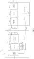
- FIG. 1 shows a block diagram of a wireless power system 100 including a wireless power transmitter 1 and a wireless power receiver 11.
- the wireless power transmitter 1 has a drive circuit 7 including an inverter 3 that drives a transmit coil 10 through a matching network 6.
- the wireless power transmitter 1 may include a regulated voltage source 2 (e.g., a voltage regulator) that provides a regulated DC voltage to the inverter 3.
- the regulated voltage source 2 produces a regulated DC output voltage in response to control stimulus from the controller 5.
- the drive circuit 7 may be a soft-switched power converter, such as a class E amplifier that converts the DC voltage at the input of inverter 3 into an AC output voltage to drive the transmit coil 10. Producing an AC output voltage enables wireless power transmission through electromagnetic induction.
- the controller 5 may control a signal generator 9 to drive the inverter 3 with signals of a selected wireless power transmission frequency.
- the inverter 3 may be switched at a frequency between 100 and 205 kHz to transmit power to a wireless power receiver designed to receive wireless power according to the Qi specification for low power Qi receivers and 80-300 kHz for medium power Qi receivers.
- the inverter 3 may be switched at a higher frequency, such as a frequency of greater than 1 MHz, within an ISM band, e.g., 6.765 MHz to 6.795 MHz, to transmit power to a receiver designed to receive wireless power using MR technology.
- Controller 5 may be an analog circuit, a digital circuit or a combination thereof. Controller 5 may be programmable, and may command signal generator 9 to produce signals at a desired transmission frequency based on stored program instructions, so that inverter 3 switches at the desired transmission frequency.
- Matching network 6 may facilitate wireless power delivery by presenting a suitable impedance to the inverter 3.
- the matching network(s) may have one or more capacitive or inductive elements or any suitable combination of capacitive and inductive elements.
- the matching network 6 may include one or more capacitive elements, which, when combined with the impedance(s) of the transmit coil 10, presents an impedance to the output of inverter 3 suitable for driving the transmit coil 10.
- the resonant frequency of the matching network 6 may be equal to or approximately equal to the switching frequency of the inverter 3.
- the transmit coil 10 may be realized by any suitable type of conductors.
- the conductors may be wires, including solid wire or Litz wire, or patterned conductors, such as patterned conductors of a PC board or an integrated circuit.
- the AC current in the transmit coil 10 generates an oscillating magnetic field in accordance with Ampere's law.
- the oscillating magnetic field induces an AC voltage into a receiver coil 12 of the wireless power receiver 11 in accordance with Faraday's law.
- the AC voltage induced in the receiver coil 12 is provided through a matching network 13 to a rectifier 14 that generates an unregulated DC voltage.
- Rectifier 14 may be a synchronous rectifier or may be implemented using diodes.
- the unregulated DC voltage is regulated using a DC/DC converter 15, the output of which may be filtered and provided to a load as output voltage Vout.
- the DC/DC converter 15 can be a linear regulator, buck regulator, boost regulator, flyback regulator or any other suitable converter.
- Control unit 16 may be an analog circuit, a digital circuit or a combination thereof, it may also be programmable. In some embodiments control unit 16 may be within the rectifier 14, or the DC/DC converter 15, or split into multiple components. In some embodiments control unit 16 may be between rectifier 14 and DC/DC converter 15.
- FIG. 2 shows a plot of the magnitude response of three transfer functions corresponding to three different spacings between the transmit and receive coils.
- the plot has frequency in kilohertz on the x-axis and transfer function magnitude on the y-axis.
- the transfer function curves are shown, using the same type of coil for both coils 10 and 12, and a load of 3.3 Ohms at the wireless power receiver.
- Curve 20 shows the transfer function with a coil separation of 6 mm.
- Curve 22 shows the transfer function with a coil separate of 3 mm.
- Curve 24 shows the transfer function with a coil separation of 0 mm.
- curve 20 is monotonic, and curves 22 and 24 are non-monotonic, over the frequency range of interest.
- the transfer function of the system may become non-monotonic as the transmit and receive coils are brought closer together, which increases the coupling between them.
- curve 20 may be a suitable transfer function, as it exhibits monotonic behavior through the entire frequency range.
- curves 22 and 24 are non-monotonic over the frequency range, and have resonant frequencies within the range at approximately 120 kHz and 145 kHz respectively.
- FIG. 3 illustrates the effect on the transfer functions of FIG. 2 when the load condition is decreased by increasing Ro from 3.3 Ohms to 9.9 Ohms, using the same separation distances between the transmit coil and the receive coil.
- decreasing the load condition by increasing Ro causes all of the transfer functions to be monotonic.
- FIG. 3 shows a plurality of transfer functions, all of which exhibit monotonic behavior.
- the plot has frequency in kilohertz on the x-axis and transfer function magnitude on the y-axis.
- the transfer function curves are shown, using a standard coil type for both coils 10 and 12, and a load of 9.9 Ohms.
- Curve 30 is a monotonic transfer function of the system, when the coil separation is approximately 6 mm.
- Curve 32 is a monotonic transfer function of the system, when the coil separation is approximately 3 mm.
- Curve 34 is a monotonic transfer function of the system, when the coil separation is approximately 0 mm. All three curves exhibit monotonic behavior over the entire operating range, in this case 110 kHz to 180 kHz. The operating range should not be considered a limitation of the present invention, and serves only to illustrate one example of monotonic behavior in a transfer function of a WPTS. As discussed below, increasing Ro decreases the loaded quality factor Q. Decreasing the loaded quality factor Q can cause the transfer function to change from non-monotonic over the frequency range of interest to monotonic.
- the inventor has recognized that certain system criteria may be selected or controlled to keep the transfer function monotonic within the operating range. Specifically, the inventor has recognized that the transfer function will be monotonic within the operating range as long as the product of the coupling coefficient K between the primary and secondary coils, and the quality factor Q of the loaded secondary coil does not exceed a constant.
- Kmax ⁇ Q ⁇ C where, C is a constant. In some embodiments, C may be 1, or 0.8, a value between 1 and 0.8, or another suitable value.
- the transfer function of the WPTS will be monotonic above resonance. Designing or controlling a wireless power transfer system such that the above equation is satisfied allows the transfer function to be monotonic for any expected loading, coupling and coil separation conditions.
- K and Q may be designed to satisfy this condition, or they may be controlled to maintain the relationship. Either K or Q may be adjusted to maintain the relationship, or both may be adjusted.
- K and/or Q may occur through a variety of implementations.
- K is determined through physical dimensions and relationships, while Q is primarily determined through electrical relationships.
- FIG. 4 is a flowchart for a method 40 of maintaining monotonic behavior of a transfer function.
- the method 40 may comprise an Act 42, which includes measuring a characteristic of the receiver 11.
- the characteristic may be a current and/or voltage, as shown in FIG. 5 , or another suitable characteristic of the signal at the receiver 11.
- Act 44 may comprise adjusting at least one of the quantities defining the quality factor Q and the coupling coefficient K, so that the product of Q and K may be below a constant C.
- the process may occur multiple times over the course of the wireless power transfer to ensure that the transfer function stays monotonic over the course of the wireless power transfer, or it may occur only once during the wireless power transfer.
- the method of FIG. 4 may be performed by control unit 16 and/or controller 5.
- FIG. 5 shows one embodiment of a wireless power receiver 11 for a wireless power transfer system.
- the wireless power receiver 11 may comprise a receiver coil 12, a matching network 13, a rectifier 14, a DC/DC converter 15, and a control unit 16 capable of performing in-band or out-of-band communication with the wireless power transmitter, as described above.
- the receiver 11 may additionally comprise a current measurement device 52, a voltage measurement device 56, a resistive impedance, 54, and a load 58.
- the current measurement device 52 and/or the voltage measurement device 56 may be part of the control unit 16.
- the resistive impedance 54 may be a representation of the equivalent resistance of the DC/DC converter 15 and the load 58, and not an actual circuit component, thus representing Ro in the equation above.
- only one of the current measurement device 52 and the voltage measurement device 56 may be needed, or any other measurement device may be used that is suitable for measuring a characteristic of the signal through the receiver 11.
- the control unit 16 uses measurements from measurement devices 52 and/or 56 to change operating conditions of the DC/DC converter 15 in a way that equivalent loading 54 of the rectifier 14 is dynamically adjusted with the techniques described above to a maintain monotonic transfer function of the wireless power system.
- the control unit 16 via in-band or out-of-band communication can request an increase of the rectifier output voltage and also can control the duty factor of the converter 15 to be reduced so the output of the receiver does not change.
- Q may be controlled through the method of FIG. 6 , by adjusting Ro.
- resistor 54 may be an adjustable impedance unit, such as a variable resistor or a bank of switchable resistors, or a representation of the equivalent resistance of the rest of the receiver 11 as described above.
- a characteristic of the receiver such as voltage or current of the signal, may be measured.
- the product of Kmax and Q can be verified to be less than the constant C.
- the controller 16 may control the value of resistor 54, such that the product of the quality factor and the coupling coefficient remains below a constant.
- the control of the value of resistor 54 may be direct, if resistor 54 is an adjustable impedance unit, or may occur through the control of the current or voltage flowing out of rectifier 14 to alter the equivalent resistance 54.
- the output voltage remains approximately constant due to the DC/DC converter 15, which can mitigate the variations in voltage and/or current caused by adjusting the value or Ro.
- Q may be controlled through the method of FIG. 7 , by adjusting C and/or L.
- C and/or L may be controlled in a variety of ways.
- C may be adjusted by controlling a frequency dependent capacitor, voltage dependent capacitor, switchable capacitor bank, or any other component with adjustable capacitance.
- L may be adjusted by controlling any variable or switchable inductive component, or an adjustable tapping of the receiver coil 12.
- a characteristic of the receiver such as voltage or current of the signal, may be measured.
- the product of Kmax and Q can be verified to be less than the constant C.
- the controller 16 may control the value of L or C, such that the product of the quality factor and the coupling coefficient remains below a constant.
- K may be controlled through the method of FIG. 8 . This embodiment may be used in combination with any of the other control schemes described.
- a characteristic of the receiver such as voltage or current of the signal, may be measured.
- the product of Kmax and Q can be verified to be less than the constant C.
- the controller 16 may control the value of K.
- K may be controlled in a variety of ways, such as through a mechanical system regulating the coupling distance between the receiver coil 12 and transmitter coil 10. The mechanical system may use a standoff distance to enforce a certain minimum spacing, keeping K below a maximum.
- the wireless power receiver target voltage may be controlled through the method of FIG. 9 .
- This embodiment may be used in combination with any of the other control schemes described.
- a characteristic of the receiver such as voltage or current of the signal, may be measured.
- the product of Kmax and Q can be verified to be less than the constant C.
- the controller 16 may control the target voltage of the wireless power receiver.
- the rectifier output voltage may be the voltage that is controlled by the closed loop.
- the nominal (set) voltage of the rectifier output voltage may be termed a "target voltage,” as the control loop controls the output voltage of the rectifier so that it becomes equal to the target voltage.
- the wireless power transmitter operating frequency may be controlled through the method of FIG. 10 .
- This embodiment may be used in combination with any of the other control schemes described.
- a characteristic of the receiver such as voltage or current of the signal, may be measured.
- the product of Kmax and Q can be verified to be less than the constant C.
- the controller 5 may control the operating frequency of the wireless power transmitter with or without use of in-band or out-of-band communication link with the controller 16.
- a wireless power transmitter may be controlled using controller 5 and a wireless power receiver may be controlled using a control unit 16, both of which may be implemented by any suitable type of circuitry.
- the controller 5 or the control unit 16 may be implemented using hardware or a combination of hardware and software.
- suitable software code can be executed on any suitable processor (e.g., a microprocessor) or collection of processors.
- the one or more controllers can be implemented in numerous ways, such as with dedicated hardware, or with general purpose hardware (e.g., one or more processors) that is programmed using microcode or software to perform the functions recited above.
- one implementation of the embodiments described herein comprises at least one computer-readable storage medium (e.g., RAM, ROM, EEPROM, flash memory or other memory technology, or other tangible, non-transitory computer-readable storage medium) encoded with a computer program (i.e., a plurality of executable instructions) that, when executed on one or more processors, performs the above-discussed functions of one or more embodiments.
- a computer program i.e., a plurality of executable instructions
- the reference to a computer program which, when executed, performs any of the above-discussed functions is not limited to an application program running on a host computer.
- computer program and software are used herein in a generic sense to reference any type of computer code (e.g., application software, firmware, microcode, or any other form of computer instruction) that can be employed to program one or more processors to implement aspects of the techniques discussed herein.
- any type of computer code e.g., application software, firmware, microcode, or any other form of computer instruction
Landscapes
- Engineering & Computer Science (AREA)
- Computer Networks & Wireless Communication (AREA)
- Power Engineering (AREA)
- Charge And Discharge Circuits For Batteries Or The Like (AREA)
Abstract
Description
- The techniques described herein relate generally to wireless power transmission.
- Wireless Power Transfer Systems (WPTS) are gaining increasing popularity as a convenient way to deliver power without wires or connectors. WPTS currently under development in the industry can be separated in two major classes: magnetic induction (MI) systems and magnetic resonance (MR) systems. Both types of systems include a wireless power transmitter (WPT) and a wireless power receiver (WPR). Such systems can be used to power or charge mobile devices such as smartphones or tablet computers, among other applications.
- Some inductive WPTS typically operate in an allocated frequency range of several hundred kilohertz using frequency variation as a power flow control mechanism.MR WPTS typically operate on a single resonant frequency using input voltage regulation to regulate output power. In typical applications, MR WPTS operate at a frequency of 6.78 MHz. Industry committees have been working on developing international standards for consumer products based on wireless power transfer.
- Some embodiments relate to at least one component for a wireless power transmitter or a wireless power receiver. The at least one component includes a mechanical structure and/or circuitry configured to maintain and/or adjust a coupling coefficient K between the wireless power transmitter and the wireless power receiver, a loaded quality factor Q of the wireless power receiver, or both, such that K times Q is less than a constant.
- The at least component may comprise circuitry configured to measure an electrical characteristic of the wireless power receiver and to adjust Q based on the electrical characteristic.
- The circuitry may comprise a current measurement device, a voltage measurement device, or both.
- The least one component may comprise circuitry that is configured to adjust Q by adjusting a capacitance, inductance, resistance, and/or loading of the wireless power receiver.
- The circuitry may be configured to adjust the capacitance by controlling a variable capacitance of the wireless power receiver.
- The circuitry may be configured to adjust the inductance by controlling a variable inductance of the wireless power receiver.
- The circuitry may be configured to adjust the resistance by controlling a variable equivalent resistance of the wireless power receiver.
- The circuitry may be configured to adjust the transmitter operating frequency.
- The constant may be between 0.8 and 1.0, inclusive.
- The mechanical structure and/or circuitry may be configured to maintain and/or adjust K, Q or both such that a transfer function from the wireless power transmitter to the wireless power receiver is monotonic within a range of drive frequencies of the wireless power transmitter.
- The at least one component may comprise a mechanical structure configured to adjust K by setting or varying a minimum distance between a transmit coil of the wireless power transmitter and a receive coil of the wireless power receiver.
- Some embodiments relate to a wireless power transmitter or a wireless power receiver comprising the at least one component.
- Some embodiments relate to a method of controlling a wireless power transmitter or a wireless power receiver. The method includes adjusting a coupling coefficient K between the wireless power transmitter and the wireless power receiver, a loaded quality factor Q of the wireless power receiver, or both, such that K times Q is less than a constant.
- The method may further comprise measuring an electrical characteristic of the wireless power receiver, wherein Q is adjusted based on the electrical characteristic.
- The electrical characteristic may comprise a current measurement, a voltage measurement, an impedance measurement and/or a resistance measurement.
- Q may be adjusted by adjusting a capacitance, inductance and/or resistance of the wireless power receiver.
- The capacitance may be adjusted by controlling a variable capacitance of the wireless power receiver.
- The inductance may be adjusted by controlling a variable inductance of the wireless power receiver.
- The resistance may be adjusted by controlling a variable resistance of the wireless power receiver.
- The constant may be between 0.8 and 1.0, inclusive.
- K, Q or both may be adjusted such that a transfer function from the wireless power transmitter to the wireless power receiver is monotonic within a range of drive frequencies of the wireless power transmitter.
- K may be adjusted by setting or varying a minimum distance between a transmit coil of the wireless power transmitter and a receive coil of the wireless power receiver.
- Some embodiments relate to wireless power transfer system including a wireless power transmitter and a wireless power receiver. The wireless power transmitter, the wireless power receiver or both the wireless power transmitter and the wireless power receiver are configured to maintain a product of the coupling coefficient K between the wireless power transmitter and the wireless power receiver and a loaded quality factor Q of the wireless power receiver to be less than a constant.
- The constant may be between 0.8 and 1.0.
- The foregoing summary is provided by way of illustration and is not intended to be limiting.
- In the drawings, each identical or nearly identical component that is illustrated in various figures is represented by a like reference character. For purposes of clarity, not every component may be labeled in every drawing. The drawings are not necessarily drawn to scale, with emphasis instead being placed on illustrating various aspects of the techniques and devices described herein.
-
FIG. 1 shows a wireless power transfer system. -
FIG. 2 shows a plurality of transfer functions, some of which exhibit non-monotonic behavior. -
FIG. 3 shows a plurality of transfer functions, all of which exhibit monotonic behavior. -
FIG. 4 is a flowchart for a method of maintaining monotonic behavior of a transfer function. -
FIG. 5 shows one embodiment of a receiver for a wireless power transfer system. -
FIG. 6 is a flowchart for a method of controlling the value of a resistance of a receiver to maintain monotonic behavior of a transfer function. -
FIG. 7 is a flowchart for a method of controlling the value of an inductance or capacitance of a receiver to maintain monotonic behavior of a transfer function. -
FIG. 8 is a flowchart for a method of controlling the value of a coupling coefficient of a receiver to maintain monotonic behavior of a transfer function. -
FIG. 9 is a flowchart for a method of controlling the target voltage of a wireless power receiver to maintain monotonic behavior of a transfer function. -
FIG. 10 is a flowchart for a method of controlling the transmitter operating frequency to maintain monotonic behavior of a transfer function. - In a WPTS the wireless power transmitter and wireless power receiver can be inductively coupled to one another. Due to the spacing between them, the coil geometry and/or placement, they may be loosely coupled to one another, i.e., the coupling coefficient may be relatively low. The load impedance seen by the wireless power transmitter may vary across a wide range as the spacing and/or placement of the wireless power receiver or the load seen by the wireless power receiver changes, due at least in part to changes in coupling. For example, the load impedance seen by the wireless power transmitter may vary if multiple receivers are placed near the transmitter, or as the depletion level of a battery charged by the transmitter varies, or if the charging rate of the battery changes.
- The transfer function of a WPTS describes the power transferred over a frequency range. The magnitude of the transfer function may have a peak at a resonant frequency of the system. It may be desirable to operate the system at a frequency higher than the resonant frequency. This method of operation has benefits related to soft switching in semiconductor devices in practical systems, which reduces the power loss during the switching of switches within the WPTS. In some embodiments, assuming that the transfer function is monotonic at frequencies higher than the resonant frequency, the closer the drive signal frequency is to the system resonant frequency, the higher the transferred power may be. The farther away from the resonant frequency F0, the lower the transferred power. In practical WPTS, the drive frequency is varied between a high operating frequency, F2, and a low operating frequency, F1. This may allow for fine control of the quantity of power transferred by the WPTS by adjusting the frequency at which power is transferred. However, the inventor has recognized that in certain combinations of loading and/or coupling the transfer function can become non-monotonic above the resonant frequency, exhibiting resonance peak splitting; the resonant frequency may be change to be substantially higher than F0. It may be undesirable to operate at a frequency above the maximum of the transfer function, as the frequency control method may no longer work effectively to control the transferred power. When the transfer function is non-monotonic above the resonant frequency, the WPTS operating range may be reduced to be between the maximum of the transfer function and the high operating frequency F2. Additionally, the range of power levels capable of being transferred may shrink as the non-monotonic behavior lowers the local maximum of the transfer function. Either of these two effects may prevent the system from reaching a desired power level in the specified operating frequency range. The techniques described herein allow for the wireless power transfer system to operate in a designated frequency range and to achieve desired levels of power transfer. The inventor has appreciated system parameters which ensure that the transfer function is monotonic across the operating frequency range, and has developed techniques to adjust one or more parameters of the system to maintain monotonic behavior of the transfer function. According to some embodiments, such techniques entail adjusting one or more system parameters to maintain a relationship between the coupling coefficient of the transmitter and receiver coils and the loaded quality factor of the receiver coil.
-
FIG. 1 shows a block diagram of awireless power system 100 including awireless power transmitter 1 and awireless power receiver 11. Thewireless power transmitter 1 has adrive circuit 7 including aninverter 3 that drives a transmitcoil 10 through amatching network 6. Thewireless power transmitter 1 may include a regulated voltage source 2 (e.g., a voltage regulator) that provides a regulated DC voltage to theinverter 3. Theregulated voltage source 2 produces a regulated DC output voltage in response to control stimulus from thecontroller 5. In some embodiments, thedrive circuit 7 may be a soft-switched power converter, such as a class E amplifier that converts the DC voltage at the input ofinverter 3 into an AC output voltage to drive the transmitcoil 10. Producing an AC output voltage enables wireless power transmission through electromagnetic induction. Thecontroller 5 may control asignal generator 9 to drive theinverter 3 with signals of a selected wireless power transmission frequency. As an example, theinverter 3 may be switched at a frequency between 100 and 205 kHz to transmit power to a wireless power receiver designed to receive wireless power according to the Qi specification for low power Qi receivers and 80-300 kHz for medium power Qi receivers. Theinverter 3 may be switched at a higher frequency, such as a frequency of greater than 1 MHz, within an ISM band, e.g., 6.765 MHz to 6.795 MHz, to transmit power to a receiver designed to receive wireless power using MR technology. However, these frequencies are described merely by way of example, as wireless power may be transmitted at a variety of suitable frequencies, in accordance with any suitable specification.Controller 5 may be an analog circuit, a digital circuit or a combination thereof.Controller 5 may be programmable, and may commandsignal generator 9 to produce signals at a desired transmission frequency based on stored program instructions, so thatinverter 3 switches at the desired transmission frequency.Matching network 6 may facilitate wireless power delivery by presenting a suitable impedance to theinverter 3. The matching network(s) may have one or more capacitive or inductive elements or any suitable combination of capacitive and inductive elements. Since the transmitcoil 10 may have an inductive impedance, in some embodiments thematching network 6 may include one or more capacitive elements, which, when combined with the impedance(s) of the transmitcoil 10, presents an impedance to the output ofinverter 3 suitable for driving the transmitcoil 10. In some embodiments, during wireless power transfer the resonant frequency of thematching network 6 may be equal to or approximately equal to the switching frequency of theinverter 3. The transmitcoil 10 may be realized by any suitable type of conductors. The conductors may be wires, including solid wire or Litz wire, or patterned conductors, such as patterned conductors of a PC board or an integrated circuit. - The AC current in the transmit
coil 10 generates an oscillating magnetic field in accordance with Ampere's law. The oscillating magnetic field induces an AC voltage into areceiver coil 12 of thewireless power receiver 11 in accordance with Faraday's law. The AC voltage induced in thereceiver coil 12 is provided through amatching network 13 to arectifier 14 that generates an unregulated DC voltage.Rectifier 14 may be a synchronous rectifier or may be implemented using diodes. The unregulated DC voltage is regulated using a DC/DC converter 15, the output of which may be filtered and provided to a load as output voltage Vout. In some embodiments, the DC/DC converter 15 can be a linear regulator, buck regulator, boost regulator, flyback regulator or any other suitable converter.Control unit 16 may be an analog circuit, a digital circuit or a combination thereof, it may also be programmable. In some embodiments controlunit 16 may be within therectifier 14, or the DC/DC converter 15, or split into multiple components. In some embodiments controlunit 16 may be betweenrectifier 14 and DC/DC converter 15. - The operation of
wireless power system 100 may be constrained by the characteristics of a transfer function of the system, as described above.FIG. 2 shows a plot of the magnitude response of three transfer functions corresponding to three different spacings between the transmit and receive coils. The plot has frequency in kilohertz on the x-axis and transfer function magnitude on the y-axis. The transfer function curves are shown, using the same type of coil for bothcoils Curve 20 shows the transfer function with a coil separation of 6 mm.Curve 22 shows the transfer function with a coil separate of 3 mm.Curve 24 shows the transfer function with a coil separation of 0 mm. - As can be seen,
curve 20 is monotonic, and curves 22 and 24 are non-monotonic, over the frequency range of interest. As shown inFIG. 2 , the transfer function of the system may become non-monotonic as the transmit and receive coils are brought closer together, which increases the coupling between them. For a desired operating range of 110 kHz to 180 kHz,curve 20 may be a suitable transfer function, as it exhibits monotonic behavior through the entire frequency range. However, curves 22 and 24 are non-monotonic over the frequency range, and have resonant frequencies within the range at approximately 120 kHz and 145 kHz respectively. As a result, withcurves curves curve 20, leading to a limited control of the power transfer, and a reduced power transfer maximum. It should be noted that while this example shows the coil separation as creating non-monotonic behavior in the transfer function over the operating range, there are other factors that may create non-monotonic transfer functions, as discussed below. -
FIG. 3 illustrates the effect on the transfer functions ofFIG. 2 when the load condition is decreased by increasing Ro from 3.3 Ohms to 9.9 Ohms, using the same separation distances between the transmit coil and the receive coil. As can be seen inFIG. 3 , decreasing the load condition by increasing Ro causes all of the transfer functions to be monotonic.FIG. 3 shows a plurality of transfer functions, all of which exhibit monotonic behavior. As withFIG. 2 , the plot has frequency in kilohertz on the x-axis and transfer function magnitude on the y-axis. The transfer function curves are shown, using a standard coil type for bothcoils Curve 30 is a monotonic transfer function of the system, when the coil separation is approximately 6 mm.Curve 32 is a monotonic transfer function of the system, when the coil separation is approximately 3 mm.Curve 34 is a monotonic transfer function of the system, when the coil separation is approximately 0 mm. All three curves exhibit monotonic behavior over the entire operating range, in thiscase 110 kHz to 180 kHz. The operating range should not be considered a limitation of the present invention, and serves only to illustrate one example of monotonic behavior in a transfer function of a WPTS. As discussed below, increasing Ro decreases the loaded quality factor Q. Decreasing the loaded quality factor Q can cause the transfer function to change from non-monotonic over the frequency range of interest to monotonic. - The inventor has recognized that certain system criteria may be selected or controlled to keep the transfer function monotonic within the operating range. Specifically, the inventor has recognized that the transfer function will be monotonic within the operating range as long as the product of the coupling coefficient K between the primary and secondary coils, and the quality factor Q of the loaded secondary coil does not exceed a constant. In equation form,

- Control of K and/or Q may occur through a variety of implementations. K is determined through physical dimensions and relationships, while Q is primarily determined through electrical relationships. Q may be expressed as

receiver 11, Cs is the capacitance of thereceiver 11, Ro is the apparent resistance of the receiver, and r is the parasitic resistance of thereceiver 11. Any of these variables may be used to control Q to establish or maintain the monotonic behavior of the transfer function of the WPTS. - A method to maintain the relationship described above, through control of K or Q, will now be discussed.
FIG. 4 is a flowchart for amethod 40 of maintaining monotonic behavior of a transfer function. Themethod 40 may comprise anAct 42, which includes measuring a characteristic of thereceiver 11. The characteristic may be a current and/or voltage, as shown inFIG. 5 , or another suitable characteristic of the signal at thereceiver 11.Act 44 may comprise adjusting at least one of the quantities defining the quality factor Q and the coupling coefficient K, so that the product of Q and K may be below a constant C. The process may occur multiple times over the course of the wireless power transfer to ensure that the transfer function stays monotonic over the course of the wireless power transfer, or it may occur only once during the wireless power transfer. In some embodiments, the method ofFIG. 4 may be performed bycontrol unit 16 and/orcontroller 5. - Applying the techniques discussed above to a wireless power receiver circuit will now be discussed.
FIG. 5 shows one embodiment of awireless power receiver 11 for a wireless power transfer system. Thewireless power receiver 11 may comprise areceiver coil 12, amatching network 13, arectifier 14, a DC/DC converter 15, and acontrol unit 16 capable of performing in-band or out-of-band communication with the wireless power transmitter, as described above. Thereceiver 11 may additionally comprise acurrent measurement device 52, avoltage measurement device 56, a resistive impedance, 54, and aload 58. In some embodiments, thecurrent measurement device 52 and/or thevoltage measurement device 56 may be part of thecontrol unit 16. In some embodiments, theresistive impedance 54 may be a representation of the equivalent resistance of the DC/DC converter 15 and theload 58, and not an actual circuit component, thus representing Ro in the equation above. In some embodiments, only one of thecurrent measurement device 52 and thevoltage measurement device 56 may be needed, or any other measurement device may be used that is suitable for measuring a characteristic of the signal through thereceiver 11. In some embodiments thecontrol unit 16 uses measurements frommeasurement devices 52 and/or 56 to change operating conditions of the DC/DC converter 15 in a way thatequivalent loading 54 of therectifier 14 is dynamically adjusted with the techniques described above to a maintain monotonic transfer function of the wireless power system. For example, in case of a DC/DC converter 15 being a buck converter, if as a result of measurements ofmeasurement devices equivalent impedance 54 is estimated of being too low to satisfy criterion Q*Ro>const, thecontrol unit 16 via in-band or out-of-band communication can request an increase of the rectifier output voltage and also can control the duty factor of theconverter 15 to be reduced so the output of the receiver does not change. - In one embodiment, Q may be controlled through the method of
FIG. 6 , by adjusting Ro. This embodiment may be used either alone or in combination with any of the other control schemes described herein. In this embodiment,resistor 54 may be an adjustable impedance unit, such as a variable resistor or a bank of switchable resistors, or a representation of the equivalent resistance of the rest of thereceiver 11 as described above. Inact 62, a characteristic of the receiver, such as voltage or current of the signal, may be measured. Inact 63, the product of Kmax and Q can be verified to be less than the constant C. Inact 64, thecontroller 16 may control the value ofresistor 54, such that the product of the quality factor and the coupling coefficient remains below a constant. The control of the value ofresistor 54 may be direct, ifresistor 54 is an adjustable impedance unit, or may occur through the control of the current or voltage flowing out ofrectifier 14 to alter theequivalent resistance 54. The output voltage remains approximately constant due to the DC/DC converter 15, which can mitigate the variations in voltage and/or current caused by adjusting the value or Ro. - In one embodiment, Q may be controlled through the method of
FIG. 7 , by adjusting C and/or L. This embodiment may be used in combination with any of the other control schemes described. C and/or L may be controlled in a variety of ways. C may be adjusted by controlling a frequency dependent capacitor, voltage dependent capacitor, switchable capacitor bank, or any other component with adjustable capacitance. Similarly, L may be adjusted by controlling any variable or switchable inductive component, or an adjustable tapping of thereceiver coil 12. Inact 72, a characteristic of the receiver, such as voltage or current of the signal, may be measured. Inact 73, the product of Kmax and Q can be verified to be less than the constant C. Inact 74, thecontroller 16 may control the value of L or C, such that the product of the quality factor and the coupling coefficient remains below a constant. - In one embodiment, K may be controlled through the method of
FIG. 8 . This embodiment may be used in combination with any of the other control schemes described. Inact 82, a characteristic of the receiver, such as voltage or current of the signal, may be measured. Inact 83, the product of Kmax and Q can be verified to be less than the constant C. Inact 84, thecontroller 16 may control the value of K. K may be controlled in a variety of ways, such as through a mechanical system regulating the coupling distance between thereceiver coil 12 andtransmitter coil 10. The mechanical system may use a standoff distance to enforce a certain minimum spacing, keeping K below a maximum. - In one embodiment, the wireless power receiver target voltage may be controlled through the method of
FIG. 9 . This embodiment may be used in combination with any of the other control schemes described. Inact 92, a characteristic of the receiver, such as voltage or current of the signal, may be measured. Inact 93, the product of Kmax and Q can be verified to be less than the constant C. Inact 94, thecontroller 16 may control the target voltage of the wireless power receiver. For example, if the wireless power transfer system is operating with control in a closed loop, the rectifier output voltage may be the voltage that is controlled by the closed loop. The nominal (set) voltage of the rectifier output voltage may be termed a "target voltage," as the control loop controls the output voltage of the rectifier so that it becomes equal to the target voltage. - In one embodiment, the wireless power transmitter operating frequency may be controlled through the method of
FIG. 10 . This embodiment may be used in combination with any of the other control schemes described. Inact 102, a characteristic of the receiver, such as voltage or current of the signal, may be measured. Inact 103, the product of Kmax and Q can be verified to be less than the constant C. Inact 104, thecontroller 5 may control the operating frequency of the wireless power transmitter with or without use of in-band or out-of-band communication link with thecontroller 16. - As discussed above, a wireless power transmitter may be controlled using
controller 5 and a wireless power receiver may be controlled using acontrol unit 16, both of which may be implemented by any suitable type of circuitry. For example, thecontroller 5 or thecontrol unit 16 may be implemented using hardware or a combination of hardware and software. When implemented using software, suitable software code can be executed on any suitable processor (e.g., a microprocessor) or collection of processors. The one or more controllers can be implemented in numerous ways, such as with dedicated hardware, or with general purpose hardware (e.g., one or more processors) that is programmed using microcode or software to perform the functions recited above. - In this respect, it should be appreciated that one implementation of the embodiments described herein comprises at least one computer-readable storage medium (e.g., RAM, ROM, EEPROM, flash memory or other memory technology, or other tangible, non-transitory computer-readable storage medium) encoded with a computer program (i.e., a plurality of executable instructions) that, when executed on one or more processors, performs the above-discussed functions of one or more embodiments. In addition, it should be appreciated that the reference to a computer program which, when executed, performs any of the above-discussed functions, is not limited to an application program running on a host computer. Rather, the terms computer program and software are used herein in a generic sense to reference any type of computer code (e.g., application software, firmware, microcode, or any other form of computer instruction) that can be employed to program one or more processors to implement aspects of the techniques discussed herein.
- Various aspects of the apparatus and techniques described herein may be used alone, in combination, or in a variety of arrangements not specifically discussed in the embodiments described in the foregoing description and is therefore not limited in its application to the details and arrangement of components set forth in the foregoing description or illustrated in the drawings. For example, aspects described in one embodiment may be combined in any manner with aspects described in other embodiments.
- Use of ordinal terms such as "first," "second," "third," etc., in the claims to modify a claim element does not by itself connote any priority, precedence, or order of one claim element over another or the temporal order in which acts of a method are performed, but are used merely as labels to distinguish one claim element having a certain name from another element having a same name (but for use of the ordinal term) to distinguish the claim elements.
- Also, the phraseology and terminology used herein is for the purpose of description and should not be regarded as limiting. The use of "including," "comprising," or "having," "containing," "involving," and variations thereof herein, is meant to encompass the items listed thereafter and equivalents thereof as well as additional items.
Claims (15)
- At least one component for a wireless power transmitter or a wireless power receiver, the at least one component comprising:a mechanical structure and/or circuitry configured to maintain and/or adjust a coupling coefficient K between the wireless power transmitter and the wireless power receiver, a loaded quality factor Q of the wireless power receiver, or both, such that K times Q is less than a constant.
- The at least one component of claim 1, wherein the at least component comprises circuitry configured to measure an electrical characteristic of the wireless power receiver and to adjust Q based on the electrical characteristic.
- The at least one component of claim 2, wherein the circuitry comprises a current measurement device, a voltage measurement device, or both.
- The at least one component of any preceding claim, wherein the at least one component comprises circuitry that is configured to adjust Q by adjusting a capacitance, inductance, resistance, and/or loading of the wireless power receiver.
- The at least one component of claim 4, wherein the circuitry is configured to adjust the capacitance by controlling a variable capacitance of the wireless power receiver, the circuitry is configured to adjust the inductance by controlling a variable inductance of the wireless power receiver and/or the circuitry is configured to adjust the resistance by controlling a variable equivalent resistance of the wireless power receiver.
- The at least one component of any preceding claim, wherein the circuitry is configured to adjust the transmitter operating frequency.
- The at least one component of any preceding claim, wherein the constant is between 0.8 and 1.0, inclusive.
- The at least one component of any preceding claim, wherein the mechanical structure and/or circuitry is configured to maintain and/or adjust K, Q or both such that a transfer function from the wireless power transmitter to the wireless power receiver is monotonic within a range of drive frequencies of the wireless power transmitter.
- The at least one component of any preceding claim, wherein the at least one component comprises a mechanical structure configured to adjust K by setting or varying a minimum distance between a transmit coil of the wireless power transmitter and a receive coil of the wireless power receiver.
- A wireless power transmitter or a wireless power receiver comprising the at least one component of any preceding claim.
- A method of controlling a wireless power transmitter or a wireless power receiver, the method comprising:adjusting a coupling coefficient K between the wireless power transmitter and the wireless power receiver, a loaded quality factor Q of the wireless power receiver, or both, such that K times Q is less than a constant.
- The method of claim 11, further comprising measuring an electrical characteristic of the wireless power receiver, wherein Q is adjusted based on the electrical characteristic.
- The method of claim 11 or 12, wherein the electrical characteristic comprises a current measurement, a voltage measurement, an impedance measurement and/or a resistance measurement.
- The method of any of claims 11-13, wherein Q is adjusted by adjusting a capacitance, inductance and/or resistance of the wireless power receiver, optionally by controlling a variable capacitance of the wireless power receiver, a variable inductance of the wireless power receiver or a variable resistance of the wireless power receiver.
- The method of any of claims 11-14, wherein the constant is between 0.8 and 1.0, inclusive.
Applications Claiming Priority (2)
| Application Number | Priority Date | Filing Date | Title |
|---|---|---|---|
| US201662346599P | 2016-06-07 | 2016-06-07 | |
| US15/481,341 US10483804B2 (en) | 2016-06-07 | 2017-04-06 | Monotonic wireless power transfer |
Publications (1)
| Publication Number | Publication Date |
|---|---|
| EP3255756A1 true EP3255756A1 (en) | 2017-12-13 |
Family
ID=59034488
Family Applications (1)
| Application Number | Title | Priority Date | Filing Date |
|---|---|---|---|
| EP17174775.1A Ceased EP3255756A1 (en) | 2016-06-07 | 2017-06-07 | Monotonic wireless power transfer |
Country Status (4)
| Country | Link |
|---|---|
| US (3) | US10483804B2 (en) |
| EP (1) | EP3255756A1 (en) |
| CN (2) | CN114793021A (en) |
| TW (1) | TWI644497B (en) |
Cited By (1)
| Publication number | Priority date | Publication date | Assignee | Title |
|---|---|---|---|---|
| EP4033640A1 (en) * | 2021-01-22 | 2022-07-27 | E.G.O. Elektro-Gerätebau GmbH | Method for operating a device for wireless transmission of energy in the direction of an electrical consumer by means of inductive coupling, device and system |
Families Citing this family (7)
| Publication number | Priority date | Publication date | Assignee | Title |
|---|---|---|---|---|
| US10186908B2 (en) * | 2015-08-04 | 2019-01-22 | Ningbo Weie Electronic Technology Co., Ltd. | Efficient power transmitting terminal, contactless power transmission device and power transmission method |
| US10483804B2 (en) | 2016-06-07 | 2019-11-19 | Mediatek Inc. | Monotonic wireless power transfer |
| US10693326B2 (en) * | 2017-07-27 | 2020-06-23 | Electronics And Telecommunications Research Institute | Wireless power receiving apparatus controlling effective load resistance, and effective load resistance control method |
| DE102018206724A1 (en) * | 2018-05-02 | 2019-11-07 | Kardion Gmbh | Energy transmission system and method for wireless energy transmission |
| US10998776B2 (en) | 2019-04-11 | 2021-05-04 | Apple Inc. | Wireless power system with in-band communications |
| CN110350673A (en) * | 2019-07-12 | 2019-10-18 | 江南大学 | A kind of impedance matching network optimization method of radio energy transmission system under maximal efficiency tracking |
| TWI829407B (en) * | 2022-10-31 | 2024-01-11 | 富達通科技股份有限公司 | Coil module with adjustable position and related control method |
Citations (2)
| Publication number | Priority date | Publication date | Assignee | Title |
|---|---|---|---|---|
| WO2015170175A1 (en) * | 2014-05-08 | 2015-11-12 | Powermat Technologies, Ltd. | Unified inductive digital protocol |
| US20160072309A1 (en) * | 2014-09-10 | 2016-03-10 | Htc Corporation | Wireless power transmitter device and wireless power receiver device |
Family Cites Families (9)
| Publication number | Priority date | Publication date | Assignee | Title |
|---|---|---|---|---|
| EP1339197A1 (en) | 2002-02-21 | 2003-08-27 | Motorola, Inc. | I/Q Mismatch compensation in an OFDM receiver in presence of frequency offset |
| AU2003226794A1 (en) | 2002-04-10 | 2003-11-10 | Nanotron Technologies Gmbh | Transceiver device |
| CN100566345C (en) | 2006-09-29 | 2009-12-02 | 湖南大学 | Wireless sensor network node locating method based on ultra broadband |
| JP2011050140A (en) * | 2009-08-26 | 2011-03-10 | Sony Corp | Non-contact electric power feeding apparatus, non-contact power electric receiver receiving apparatus, non-contact electric power feeding method, non-contact electric power receiving method and non-contact electric power feeding system |
| EP2455253A3 (en) * | 2010-10-27 | 2012-09-12 | Equos Research Co., Ltd. | Electric power transmission system and antenna |
| US20140152250A1 (en) * | 2012-11-30 | 2014-06-05 | General Electric Company | System and method for controlling output power in a contactless power transfer system |
| KR20230062668A (en) * | 2014-05-26 | 2023-05-09 | 지이 하이브리드 테크놀로지스, 엘엘씨 | Contactless power reception device and reception method |
| JP6402818B2 (en) * | 2015-02-20 | 2018-10-10 | 富士通株式会社 | Power receiver and power transmission system |
| US10483804B2 (en) | 2016-06-07 | 2019-11-19 | Mediatek Inc. | Monotonic wireless power transfer |
-
2017
- 2017-04-06 US US15/481,341 patent/US10483804B2/en active Active
- 2017-05-17 CN CN202210344214.5A patent/CN114793021A/en active Pending
- 2017-05-17 CN CN201710348569.0A patent/CN107482788B/en active Active
- 2017-05-23 TW TW106116984A patent/TWI644497B/en active
- 2017-06-07 EP EP17174775.1A patent/EP3255756A1/en not_active Ceased
-
2019
- 2019-09-24 US US16/581,012 patent/US11128174B2/en active Active
-
2021
- 2021-08-10 US US17/398,878 patent/US11632000B2/en active Active
Patent Citations (2)
| Publication number | Priority date | Publication date | Assignee | Title |
|---|---|---|---|---|
| WO2015170175A1 (en) * | 2014-05-08 | 2015-11-12 | Powermat Technologies, Ltd. | Unified inductive digital protocol |
| US20160072309A1 (en) * | 2014-09-10 | 2016-03-10 | Htc Corporation | Wireless power transmitter device and wireless power receiver device |
Cited By (1)
| Publication number | Priority date | Publication date | Assignee | Title |
|---|---|---|---|---|
| EP4033640A1 (en) * | 2021-01-22 | 2022-07-27 | E.G.O. Elektro-Gerätebau GmbH | Method for operating a device for wireless transmission of energy in the direction of an electrical consumer by means of inductive coupling, device and system |
Also Published As
| Publication number | Publication date |
|---|---|
| US20200021139A1 (en) | 2020-01-16 |
| US20170353053A1 (en) | 2017-12-07 |
| TWI644497B (en) | 2018-12-11 |
| US11128174B2 (en) | 2021-09-21 |
| TW201743536A (en) | 2017-12-16 |
| CN114793021A (en) | 2022-07-26 |
| US10483804B2 (en) | 2019-11-19 |
| CN107482788A (en) | 2017-12-15 |
| US11632000B2 (en) | 2023-04-18 |
| CN107482788B (en) | 2022-04-26 |
| US20220200347A1 (en) | 2022-06-23 |
Similar Documents
| Publication | Publication Date | Title |
|---|---|---|
| US11632000B2 (en) | Monotonic wireless power transfer | |
| US20210057939A1 (en) | Detecting foreign objects in wireless power transfer systems | |
| EP3232535B1 (en) | Wireless power transmitter | |
| EP3664254B1 (en) | Detecting foreign objects in wireless power transfer systems | |
| KR20180031469A (en) | Apparatus for transmitting power wirelessly and control method thereof | |
| EP3176910B1 (en) | Methods and devices for protection in wireless power systems | |
| EP3065282B1 (en) | Dynamic reduction of synchronous rectifier power losses | |
| EP2722966A1 (en) | Resonance-type non-contact power supply system | |
| EP3127209A1 (en) | Low power inductive power receiver | |
| US20200083748A1 (en) | Noncontact power supply apparatus | |
| WO2020015749A1 (en) | Detecting foreign objects in wireless power transfer systems | |
| KR20140108135A (en) | Wireless power supply system | |
| US11228207B2 (en) | Power receiving device, control method thereof, and feed system | |
| CN107408845B (en) | Wireless power receiver | |
| CN110582923B (en) | Non-contact power supply device | |
| CN113557657B (en) | Control method of power conversion device and power conversion device | |
| WO2017078543A1 (en) | Inductive power receiver | |
| KR101341086B1 (en) | Adjustable output voltage automatic voltage regulator | |
| KR101883326B1 (en) | Precise control power saver using inductive voltage control | |
| JP2016081750A (en) | Power transmission device, non-contact power supply device and induction heating apparatus | |
| WO2015151492A1 (en) | Non-contact power supply device and non-contact power supply system | |
| KR20160023103A (en) | Wireless charging power receiving device and operating method of the wireless charging power receiving device | |
| KR20090078886A (en) | Voltage division apparatus for transformer |
Legal Events
| Date | Code | Title | Description |
|---|---|---|---|
| PUAI | Public reference made under article 153(3) epc to a published international application that has entered the european phase |
Free format text: ORIGINAL CODE: 0009012 |
|
| STAA | Information on the status of an ep patent application or granted ep patent |
Free format text: STATUS: THE APPLICATION HAS BEEN PUBLISHED |
|
| AK | Designated contracting states |
Kind code of ref document: A1 Designated state(s): AL AT BE BG CH CY CZ DE DK EE ES FI FR GB GR HR HU IE IS IT LI LT LU LV MC MK MT NL NO PL PT RO RS SE SI SK SM TR |
|
| AX | Request for extension of the european patent |
Extension state: BA ME |
|
| STAA | Information on the status of an ep patent application or granted ep patent |
Free format text: STATUS: REQUEST FOR EXAMINATION WAS MADE |
|
| 17P | Request for examination filed |
Effective date: 20180613 |
|
| RBV | Designated contracting states (corrected) |
Designated state(s): AL AT BE BG CH CY CZ DE DK EE ES FI FR GB GR HR HU IE IS IT LI LT LU LV MC MK MT NL NO PL PT RO RS SE SI SK SM TR |
|
| STAA | Information on the status of an ep patent application or granted ep patent |
Free format text: STATUS: EXAMINATION IS IN PROGRESS |
|
| 17Q | First examination report despatched |
Effective date: 20190814 |
|
| STAA | Information on the status of an ep patent application or granted ep patent |
Free format text: STATUS: EXAMINATION IS IN PROGRESS |
|
| APBK | Appeal reference recorded |
Free format text: ORIGINAL CODE: EPIDOSNREFNE |
|
| APBN | Date of receipt of notice of appeal recorded |
Free format text: ORIGINAL CODE: EPIDOSNNOA2E |
|
| APBR | Date of receipt of statement of grounds of appeal recorded |
Free format text: ORIGINAL CODE: EPIDOSNNOA3E |
|
| APAF | Appeal reference modified |
Free format text: ORIGINAL CODE: EPIDOSCREFNE |
|
| P01 | Opt-out of the competence of the unified patent court (upc) registered |
Effective date: 20230607 |
|
| APBT | Appeal procedure closed |
Free format text: ORIGINAL CODE: EPIDOSNNOA9E |
|
| STAA | Information on the status of an ep patent application or granted ep patent |
Free format text: STATUS: THE APPLICATION HAS BEEN REFUSED |
|
| 18R | Application refused |
Effective date: 20231219 |