EP3255252A1 - Blade outer air seal made of ceramic matrix composite - Google Patents
Blade outer air seal made of ceramic matrix composite Download PDFInfo
- Publication number
- EP3255252A1 EP3255252A1 EP17174691.0A EP17174691A EP3255252A1 EP 3255252 A1 EP3255252 A1 EP 3255252A1 EP 17174691 A EP17174691 A EP 17174691A EP 3255252 A1 EP3255252 A1 EP 3255252A1
- Authority
- EP
- European Patent Office
- Prior art keywords
- layers
- boas
- segment
- recited
- outer air
- Prior art date
- Legal status (The legal status is an assumption and is not a legal conclusion. Google has not performed a legal analysis and makes no representation as to the accuracy of the status listed.)
- Granted
Links
- 239000011153 ceramic matrix composite Substances 0.000 title claims abstract description 24
- 239000000463 material Substances 0.000 claims abstract description 11
- 230000014759 maintenance of location Effects 0.000 claims description 14
- 238000000576 coating method Methods 0.000 claims description 10
- 239000000919 ceramic Substances 0.000 claims description 8
- XUIMIQQOPSSXEZ-UHFFFAOYSA-N Silicon Chemical compound [Si] XUIMIQQOPSSXEZ-UHFFFAOYSA-N 0.000 claims description 4
- 239000010703 silicon Substances 0.000 claims description 4
- 229910052710 silicon Inorganic materials 0.000 claims description 4
- 210000005069 ears Anatomy 0.000 abstract description 7
- 239000007789 gas Substances 0.000 description 19
- 239000011248 coating agent Substances 0.000 description 6
- 239000000567 combustion gas Substances 0.000 description 6
- 239000000835 fiber Substances 0.000 description 6
- 239000000446 fuel Substances 0.000 description 6
- 230000003068 static effect Effects 0.000 description 5
- 230000004048 modification Effects 0.000 description 4
- 238000012986 modification Methods 0.000 description 4
- 238000012360 testing method Methods 0.000 description 4
- 239000000945 filler Substances 0.000 description 3
- 238000000034 method Methods 0.000 description 3
- 125000006850 spacer group Chemical group 0.000 description 3
- 230000004323 axial length Effects 0.000 description 2
- 239000000284 extract Substances 0.000 description 2
- 239000011159 matrix material Substances 0.000 description 2
- 238000007789 sealing Methods 0.000 description 2
- HBMJWWWQQXIZIP-UHFFFAOYSA-N silicon carbide Chemical compound [Si+]#[C-] HBMJWWWQQXIZIP-UHFFFAOYSA-N 0.000 description 2
- 229910010271 silicon carbide Inorganic materials 0.000 description 2
- 229920000049 Carbon (fiber) Polymers 0.000 description 1
- 229920000914 Metallic fiber Polymers 0.000 description 1
- 229910000831 Steel Inorganic materials 0.000 description 1
- 238000003491 array Methods 0.000 description 1
- 230000000712 assembly Effects 0.000 description 1
- 238000000429 assembly Methods 0.000 description 1
- 238000005452 bending Methods 0.000 description 1
- 230000009286 beneficial effect Effects 0.000 description 1
- 230000008901 benefit Effects 0.000 description 1
- 230000005540 biological transmission Effects 0.000 description 1
- 239000004917 carbon fiber Substances 0.000 description 1
- 239000012700 ceramic precursor Substances 0.000 description 1
- 230000008859 change Effects 0.000 description 1
- 230000005465 channeling Effects 0.000 description 1
- 238000006243 chemical reaction Methods 0.000 description 1
- 230000000295 complement effect Effects 0.000 description 1
- 238000007596 consolidation process Methods 0.000 description 1
- 238000012937 correction Methods 0.000 description 1
- 238000005336 cracking Methods 0.000 description 1
- 230000007423 decrease Effects 0.000 description 1
- 230000032798 delamination Effects 0.000 description 1
- 230000004069 differentiation Effects 0.000 description 1
- 230000005611 electricity Effects 0.000 description 1
- 238000000605 extraction Methods 0.000 description 1
- 238000011049 filling Methods 0.000 description 1
- 238000011065 in-situ storage Methods 0.000 description 1
- 230000000977 initiatory effect Effects 0.000 description 1
- 238000011068 loading method Methods 0.000 description 1
- 238000004519 manufacturing process Methods 0.000 description 1
- 239000002184 metal Substances 0.000 description 1
- 239000000203 mixture Substances 0.000 description 1
- 239000003921 oil Substances 0.000 description 1
- 239000002243 precursor Substances 0.000 description 1
- 230000008569 process Effects 0.000 description 1
- 230000009467 reduction Effects 0.000 description 1
- 239000011347 resin Substances 0.000 description 1
- 229920005989 resin Polymers 0.000 description 1
- 230000000717 retained effect Effects 0.000 description 1
- 239000007921 spray Substances 0.000 description 1
- 239000010959 steel Substances 0.000 description 1
- 230000002123 temporal effect Effects 0.000 description 1
Images


Classifications
-
- F—MECHANICAL ENGINEERING; LIGHTING; HEATING; WEAPONS; BLASTING
- F01—MACHINES OR ENGINES IN GENERAL; ENGINE PLANTS IN GENERAL; STEAM ENGINES
- F01D—NON-POSITIVE DISPLACEMENT MACHINES OR ENGINES, e.g. STEAM TURBINES
- F01D11/00—Preventing or minimising internal leakage of working-fluid, e.g. between stages
- F01D11/08—Preventing or minimising internal leakage of working-fluid, e.g. between stages for sealing space between rotor blade tips and stator
-
- F—MECHANICAL ENGINEERING; LIGHTING; HEATING; WEAPONS; BLASTING
- F01—MACHINES OR ENGINES IN GENERAL; ENGINE PLANTS IN GENERAL; STEAM ENGINES
- F01D—NON-POSITIVE DISPLACEMENT MACHINES OR ENGINES, e.g. STEAM TURBINES
- F01D25/00—Component parts, details, or accessories, not provided for in, or of interest apart from, other groups
- F01D25/24—Casings; Casing parts, e.g. diaphragms, casing fastenings
-
- F—MECHANICAL ENGINEERING; LIGHTING; HEATING; WEAPONS; BLASTING
- F01—MACHINES OR ENGINES IN GENERAL; ENGINE PLANTS IN GENERAL; STEAM ENGINES
- F01D—NON-POSITIVE DISPLACEMENT MACHINES OR ENGINES, e.g. STEAM TURBINES
- F01D25/00—Component parts, details, or accessories, not provided for in, or of interest apart from, other groups
- F01D25/28—Supporting or mounting arrangements, e.g. for turbine casing
-
- F—MECHANICAL ENGINEERING; LIGHTING; HEATING; WEAPONS; BLASTING
- F05—INDEXING SCHEMES RELATING TO ENGINES OR PUMPS IN VARIOUS SUBCLASSES OF CLASSES F01-F04
- F05D—INDEXING SCHEME FOR ASPECTS RELATING TO NON-POSITIVE-DISPLACEMENT MACHINES OR ENGINES, GAS-TURBINES OR JET-PROPULSION PLANTS
- F05D2220/00—Application
- F05D2220/30—Application in turbines
- F05D2220/32—Application in turbines in gas turbines
-
- F—MECHANICAL ENGINEERING; LIGHTING; HEATING; WEAPONS; BLASTING
- F05—INDEXING SCHEMES RELATING TO ENGINES OR PUMPS IN VARIOUS SUBCLASSES OF CLASSES F01-F04
- F05D—INDEXING SCHEME FOR ASPECTS RELATING TO NON-POSITIVE-DISPLACEMENT MACHINES OR ENGINES, GAS-TURBINES OR JET-PROPULSION PLANTS
- F05D2240/00—Components
- F05D2240/10—Stators
- F05D2240/11—Shroud seal segments
-
- F—MECHANICAL ENGINEERING; LIGHTING; HEATING; WEAPONS; BLASTING
- F05—INDEXING SCHEMES RELATING TO ENGINES OR PUMPS IN VARIOUS SUBCLASSES OF CLASSES F01-F04
- F05D—INDEXING SCHEME FOR ASPECTS RELATING TO NON-POSITIVE-DISPLACEMENT MACHINES OR ENGINES, GAS-TURBINES OR JET-PROPULSION PLANTS
- F05D2260/00—Function
- F05D2260/30—Retaining components in desired mutual position
-
- F—MECHANICAL ENGINEERING; LIGHTING; HEATING; WEAPONS; BLASTING
- F05—INDEXING SCHEMES RELATING TO ENGINES OR PUMPS IN VARIOUS SUBCLASSES OF CLASSES F01-F04
- F05D—INDEXING SCHEME FOR ASPECTS RELATING TO NON-POSITIVE-DISPLACEMENT MACHINES OR ENGINES, GAS-TURBINES OR JET-PROPULSION PLANTS
- F05D2300/00—Materials; Properties thereof
- F05D2300/60—Properties or characteristics given to material by treatment or manufacturing
- F05D2300/603—Composites; e.g. fibre-reinforced
- F05D2300/6033—Ceramic matrix composites [CMC]
-
- Y—GENERAL TAGGING OF NEW TECHNOLOGICAL DEVELOPMENTS; GENERAL TAGGING OF CROSS-SECTIONAL TECHNOLOGIES SPANNING OVER SEVERAL SECTIONS OF THE IPC; TECHNICAL SUBJECTS COVERED BY FORMER USPC CROSS-REFERENCE ART COLLECTIONS [XRACs] AND DIGESTS
- Y02—TECHNOLOGIES OR APPLICATIONS FOR MITIGATION OR ADAPTATION AGAINST CLIMATE CHANGE
- Y02T—CLIMATE CHANGE MITIGATION TECHNOLOGIES RELATED TO TRANSPORTATION
- Y02T50/00—Aeronautics or air transport
- Y02T50/60—Efficient propulsion technologies, e.g. for aircraft
Definitions
- Gas turbine engines typically include a compressor section, a combustor section, and a turbine section. During operation, air is pressurized in the compressor section and is mixed with fuel and burned in the combustor section to generate hot combustion gases. The hot combustion gases are communicated through the turbine section, which extracts energy from the hot combustion gases to power the compressor section and other loads.
- the compressor and turbine sections of a gas turbine engine include alternating rows of rotating blades and stationary vanes.
- the turbine blades rotate and extract energy from the hot combustion gases that are communicated through the gas turbine engine.
- the turbine vanes direct the hot combustion gases at a preferred angle of entry into a downstream row of blades.
- An engine case of an engine static structure may include one or more blade outer air seals (BOAS), which are typically formed of metal, that establish an outer radial flow path boundary for channeling the hot combustion gases.
- BOAS blade outer air seals
- a transversely concave inner diameter (ID) surface is along a main body portion and extends from a first circumferential end to a second circumferential end.
- a first mounting ear extends outward from the main body portion. The first mounting ear and a first end portion of the main body portion to define a first circumferentially outwardly open mounting recess.
- a second mounting ear extends outward from the main body portion. The second mounting ear and a second end portion of the main body portion define a second circumferentially outwardly open mounting recess.
- An outwardly open well is between the first mounting ear and the second mounting ear.
- a plurality of layers are formed of a ceramic matrix composite (CMC) material and includes a first plurality extending along the first circumferentially outwardly open mounting recess; a second plurality extending along the second circumferentially outwardly open mounting recess; and a third plurality extending along from the first mounting ear to the second mounting ear.
- One or more first wedges are between layers of said plurality of layers along the first mounting ear to circumferentially flare the layers along the first mounting ear.
- One or more second wedges are between layers of said plurality of layers along the second mounting ear to circumferentially flare the layers along the second mounting ear.
- An embodiment may additionally and/or alternatively include, the plurality of layers further including: one or more fourth layers between the first plurality of layers and the inner diameter (ID) surface; and one or more fifth layers between the second plurality of layers and the inner diameter (ID) surface.
- a further embodiment may additionally and/or alternatively include, the plurality of layers further including: one or more sixth layers between: on the one hand, the one or more fourth layers, the third plurality of layers, and the one or more fifth layers; and on the other hand, the inner diameter (ID) surface.
- the plurality of layers further including: one or more sixth layers between: on the one hand, the one or more fourth layers, the third plurality of layers, and the one or more fifth layers; and on the other hand, the inner diameter (ID) surface.
- a further embodiment may additionally and/or alternatively include, a base structure comprising the first, second, and third pluralities of layers and the plurality of layers further comprising an overwrap layer over the base structure.
- a further embodiment may additionally and/or alternatively include, the overwrap layer overwrapping forward and aft ends of the base structure.
- a further embodiment may additionally and/or alternatively include, the first and second pluralities of layers being curved in substantially a C-shape to respectively provide the first and second mounting recesses.
- a further embodiment may additionally and/or alternatively include, the one or more first wedges and the one or more second wedges comprising CMC or monolithic ceramic.
- a further embodiment may additionally and/or alternatively include, the one or more first wedges and the one or more second wedges having a peak thickness of at least 0.15 mm.
- a further embodiment may additionally and/or alternatively include, the one or more first wedges and the one or more second wedges respectively fanning each of the first mounting ear and the second mounting ear by at least 15.0°.
- a further embodiment may additionally and/or alternatively include, a first load-distributing member along the first mounting recess and a second load-distributing member along the second mounting recess.
- a further embodiment may additionally and/or alternatively include, the first load-distributing member and the second load-distributing member being coatings.
- a further embodiment may additionally and/or alternatively include, the first load-distributing member and the second load-distributing member being silicon-based.
- a further embodiment may additionally and/or alternatively include, the first load-distributing member and the second load-distributing member having peak thickness of at least 0.05 mm.
- a gas turbine engine comprising: an engine case: a circumferential array of blade outer air seal (BOAS) segments; and a plurality of retention blocks attached to the engine case and each comprising a first portion received in the first recess of a first adjacent said BOAS segment and a second portion received in the second recess of a second adjacent said BOAS segment to support the BOAS segments relative to the engine case.
- BOAS blade outer air seal
- An embodiment may additionally and/or alternatively include, the retention block first portion and the retention block second portion respectively contacting coatings on the respective associated BOAS segments.
- a further embodiment may additionally and/or alternatively include, a plurality of wedge seals respectively between the plurality of retention blocks and their associated BOAS segments.
- FIG. 1 schematically and non-limitingly illustrates a gas turbine engine 20 that includes a fan section 22, a compressor section 24, a combustor section 26, and a turbine section 28.
- the exemplary illustrated engine is a two-spool engine as discussed below.
- Alternative engines might include an augmenter section (not shown) among other systems or features.
- the fan section 22 drives air along a bypass flow path B while the fan section and compressor section 24 drive a core airflow in along a core flow path C where air is compressed and communicated to the combustor section 26.
- the combustor section 26 air is mixed with fuel and ignited to generate a high pressure exhaust gas stream that expands through the turbine section 28 where energy is extracted and utilized to drive the fan section 22 and the compressor section 24.
- turbofan gas turbine engine depicts a turbofan gas turbine engine
- the concepts described herein are not limited to use with turbofans as the teachings may be applied to other types of turbine engines; for example a turbine engine including a three-spool architecture in which three spools concentrically rotate about a common axis and where a low spool enables a low pressure turbine to drive a fan via a gearbox, an intermediate spool that enables an intermediate pressure turbine to drive a first compressor of the compressor section, and a high spool that enables a high pressure turbine to drive a high pressure compressor of the compressor section.
- the concepts disclosed herein can further be applied outside of gas turbine engines.
- the example engine 20 generally includes a low speed spool 30 and a high speed spool 32 mounted for rotation about an engine central longitudinal axis A relative to an engine static structure 36 via several bearing systems 38. It should be understood that various bearing systems 38 at various locations may alternatively or additionally be provided.
- the low speed spool 30 generally includes an inner shaft 40 that connects a fan 42 and a low pressure (or first) compressor section 44 to a low pressure (or first) turbine section 46.
- the inner shaft 40 drives the fan 42 through a speed change device, such as a geared architecture 48, to drive the fan 42 at a lower speed than the low speed spool 30.
- the high speed spool 32 includes an outer shaft 50 that interconnects a high pressure (or second) compressor section 52 and a high pressure (or second) turbine section 54.
- the inner shaft 40 and the outer shaft 50 are concentric and rotate via the bearing systems 38 about the engine central longitudinal axis A.
- a combustor 56 is arranged between the high pressure compressor 52 and the high pressure turbine 54.
- the high pressure turbine 54 includes at least two stages to provide a double stage high pressure turbine 54.
- the high pressure turbine 54 includes only a single stage.
- a "high pressure" compressor or turbine experiences a higher pressure than a corresponding "low pressure” compressor or turbine.
- the example low pressure turbine 46 has a pressure ratio that is greater than about five.
- the pressure ratio of the example low pressure turbine 46 is measured prior to an inlet of the low pressure turbine 46 as related to the pressure measured at the outlet of the low pressure turbine 46 prior to an exhaust nozzle.
- a mid-turbine frame 58 of the engine static structure 36 is arranged generally between the high pressure turbine 54 and the low pressure turbine 46.
- the mid-turbine frame 58 further supports bearing systems 38 in the turbine section 28 as well as setting airflow entering the low pressure turbine 46.
- the core airflow is compressed by the low pressure compressor 44 then by the high pressure compressor 52 mixed with fuel and ignited in the combustor 56 to produce high speed exhaust gases that are then expanded through the high pressure turbine 54 and low pressure turbine 46.
- the mid-turbine frame 58 includes vanes 60, which are in the core airflow path C and function as an inlet guide vane for the low pressure turbine 46. Utilizing the vane 60 of the mid-turbine frame 58 as the inlet guide vane for low pressure turbine 46 decreases the length of the low pressure turbine 46 without increasing the axial length of the mid-turbine frame 58. Reducing or eliminating the number of vanes in the low pressure turbine 46 shortens the axial length of the turbine section 28. Thus, the compactness of the gas turbine engine 20 is increased and a higher power density may be achieved.
- the disclosed gas turbine engine 20 in one example is a high-bypass geared aircraft engine.
- the gas turbine engine 20 includes a bypass ratio greater than about six, with an example embodiment being greater than about ten.
- the example geared architecture 48 is an epicyclical gear train, such as a planetary gear system, star gear system or other known gear system, with a gear reduction ratio of greater than about 2.3.
- the gas turbine engine 20 includes a bypass ratio greater than about ten and the fan diameter is significantly larger than an outer diameter of the low pressure compressor 44. It should be understood, however, that the above parameters are only exemplary of one embodiment of a gas turbine engine including a geared architecture and that the present disclosure is applicable to other gas turbine engines.
- the fan section 22 of the engine 20 is designed for a particular flight condition-typically cruise at about 0.8 Mach and about 35,000 feet (10.7 km).
- Low fan pressure ratio is the pressure ratio across the fan blade alone, without a Fan Exit Guide Vane (“FEGV”) system.
- the low fan pressure ratio as disclosed herein according to one non-limiting embodiment is less than about 1.50. In another non-limiting embodiment the low fan pressure ratio is less than about 1.45.
- the "Low corrected fan tip speed,” as disclosed herein according to one non-limiting embodiment, is less than about 1150 ft/second (351 m/s).
- FIG. 2 is a perspective view of a portion 62 of the gas turbine engine 20 of FIG. 1 .
- the portion 62 is a portion of the high pressure turbine 54. It should be understood, however, that other portions of the gas turbine engine 20 may benefit from the teachings of this disclosure, including but not limited to the fan section 22, the compressor section 24, and the low pressure turbine 46.
- a rotor disk 64 (only one shown, although multiple disks could be axially disposed within the portion 62) is configured to rotate about the engine central longitudinal axis A.
- the portion 62 includes an array of rotating blades 66 (only one shown), which are mounted to the rotor disk 64, and arrays of static vane assemblies (not shown) on axial sides of the blades 66.
- Each blade 66 includes a blade tip 66T at a radially outermost portion thereof.
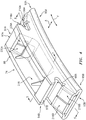
- the rotor disk 64 is arranged such that the blade tips 66T are located adjacent a blade outer air seal (BOAS) assembly 68.
- the BOAS assembly 68 may find beneficial use in many industries including aerospace, industrial, electricity generation, naval propulsion, pumps for gas in oil transmission, aircraft propulsion, vehicle engines and stationary power plants.
- the BOAS assembly 68 is disposed in an annulus radially between an engine case (such as an outer casing 70 of the engine 20) and the blade tips 66T.
- the BOAS assembly 68 includes a support structure 72 and a plurality of BOAS segments 74.
- the BOAS segments 74 may be arranged to form a segmented full ring hoop assembly that circumferentially surrounds the associated blades 66, which provides a sealing surface for the blade tips 66T to prevent leakage of the core airflow over to the blades 66.
- the individual BOAS segments 74 may be referred to individually as a "BOAS segment” or simply a "BOAS.”
- the support structure 72 includes a retention block 76 fastened to the engine outer casing 70 by a fastener 78.
- the retention block 76 includes tapered arms 80, 82 on circumferentially opposed sides thereof.
- the tapered arms 80, 82 in this example are rounded, and are to be received within a corresponding curved end of a respective BOAS segment 74 (as will be explained below).
- FIG. 3 also shows a wedge seal 79 sealing the inter-segment gap and retained in a compartment in the inner diameter (ID) face of the retention block 76.
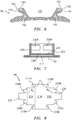
- FIG. 4 illustrates the detail of an example of a BOAS segment 74.
- the BOAS segment 74 is primarily made of a ceramic matrix composite (CMC) material.
- CMC materials include a ceramic matrix and a plurality of fibers suspended in that ceramic matrix.
- the fibers can be a ceramic fibers, silicon carbide fibers, carbon fibers, or metallic fibers, as examples.
- additional fillers may be added beyond those of the '764 publication in order to reorient plies/layers of the CMC to better resist fracture.
- the circumferential direction Y is normal to the engine central longitudinal axis A.
- the exemplary BOAS segment 74 includes a base structure or core 84 ( FIG. 6 ) and an overwrap layer 86 ( FIGS. 5 and 8 ).
- the detail of the base structure 84 is perhaps best seen with reference to FIG. 5 , which is a cross-sectional view taken along lines 5-5 in FIG. 4 .
- FIG. 6 does not include the overwrap layer 86.
- the BOAS segment 74 has a main body portion 90 having an inner diameter (ID) surface 92 and extending between a first circumferential end 93A and a second circumferential end 93B ( FIG. 4 ).
- the BOAS segment further comprises a pair of mounting ears 94A and 94B radially outward of the main body 90 and separated from adjacent main body end portions 95A, 95B by associated longitudinal channels (also referred to as recesses or slots) 96A, 96B circumferentially outwardly open.
- the mounting ears have respective circumferentially outboard ends 97A, 97B.
- the mounting ears and the respective adjacent main body end portions cooperate to define the respective recesses.
- the base structure 84 comprises a number of groups of plies.
- One group 98 of plies may form a bridge extending centrally along the main body and then outward along the mounting ears to leave a central channel, well, or recess 100 radially outwardly open.
- Another group 120 of plies extends along the mounting ear circumferentially outboard of adjacent portions of the plies 98 and along the main body portion 95A or 95B thus bending around an arc to form the associated recess 96A or 96B. Accordingly, respective groups 120 may be at opposite circumferential ends of the structure 84.
- groups 130 of plies may build thickness of the associated portion 95A or 95B terminating adjacent the bend of the group 98.
- one or more plies 140 extend essentially full circumferential span radially inward of the groups 98 and 130 and thus generally parallel to the surface 92.
- FIG. 5 further shows a filler or spacer 150 similar to that of the '764 publication filling a gap at the bend of the group 120.
- FIG. 5 also shows several further modifications relative to the '764 publication.
- a first modification involves the use of wedges 160, 162, 164 to fan out the plies along the mounting ears.
- the exemplary wedges are positioned between plies of the group 120; however the wedges may also be within the group 98.
- the wedges may be used to orient the plies to maximally resist loads that would otherwise cause cracking.
- Wedge materials may be similar to those of the wedge/spacer 150.
- the wedges may be made of a CMC. In one group of examples, these are initially formed as a mix of ceramic fibers and a ceramic-precursor resin material (e.g., molded). This molded material in a green state may be laid up with the plies or their precursors (fully or partially processed/cured CMC). In other examples, the wedges may be made of a monolithic ceramic or a fully processed CMC material.
- Exemplary individual wedges have peak thickness of at least 0.15 mm, more specifically 0.15 mm to 5.0 mm, more specifically, 0.30 mm to 3.0 mm.
- the individual wedges may have an included angle of 2.0° to 15.0°, more specifically 4.0° to 12.0°.
- the wedges may fan the plies by a net angle of at least 15.0°, more specifically 15° to 70°, more specifically 20° to 55° or 35° to 50°. In a reengineering of a baseline BOAS segment this may be effective to reorient the side surface of the well 100 (formed by the group 98) by that same angle.
- Such reengineering may bring the side surface close to radial (e.g., within 20°, more specifically within 10°, or within 5°). Likely, it will be at least 2° off radial to allow radial extraction of the tool (e.g., functioning as a mandrel to form the well).
- a second modification is the addition of a load distributing member 170 atop the outermost ply of the group 120 along the outboard surface of the recess 96A, 96B.
- the member 170 interfaces with the retention block and helps to distribute loads.
- the exemplary member 170 is formed in situ as a coating.
- An exemplary coating is silicon based such as silicon and/or silicon carbide.
- An exemplary application technique is plasma spray.
- An exemplary thickness is 0.05 mm to 0.50 mm, more specifically, 0.07 mm to 0.15 mm at least locally/peak, optionally feathering or tapering out.
- Exemplary coating properties may have the coating harder than the CMC to reduce pressure concentrations in the CMC. The coating may be sprayed to a greater thickness and then ground down.
- FIG. 9 shows a static load test system 300 comprising a test fixture 302 and a ram 304.
- the ram simulates pressure loading such as shown by arrows in FIG. 3A .
- the fixture 302 has a generally upwardly open channel-like section wherein the walls of the channel end in features 306A, 306B for simulating the portions of the two retention blocks that would interface with a given steel segment.
- the ram 304 has an underside 310 complementary to the outer diameter (OD) well 100 of the BOAS segment to simulate pressure loads.
- FIG. 9 shows a fracture path 350 extending through the mounting ear.
- This has been observed as intersecting the well 100 at an angle substantially off-normal to the surface of the well.
- the off-normality indicates that the plies are not oriented to best resist the stresses.
- An exemplary re-engineering involves adding the wedges 162, 164 to shift the plies of the group 98 ( FIG. 5 ) to an orientation more normal to the observed fracture 350. In the exemplary embodiment, this involves deepening the wall surface (making more radial rather than more circumferential).
- the member 170 may distribute loads from the retention block to further limit crack initiation at the recess 96A, 96B.
- the base structure 84 is held together in one example by an overwrap layer 86.
- the overwrap layer 86 is provided by either a single CMC sheet or a plurality of layered CMC sheets defining a single overwrap layer 86.
- the overwrap layer 86 may be provided using a PIP, CVI or CVD process.
- the overwrap layer 86 includes a central body portion 214 ( FIG. 8 ) having a plurality of flaps and projections extending therefrom. When formed, the central body portion 214 forms a radially innermost layer of the BOAS segment.
- the overwrap layer may be initially formed oversized in some locations and then machined down after a consolidation step to then form the final shape of the BOAS segment.
- the central body portion 214 includes a first pair of projections 216A, 218A which provide overwrap at the first end portion 95A.
- the overwrap layer similarly includes a pair of projections 216B, 218B which provide overwrap at the second end portion 95B.
- the overwrap layer 86 is bent about a first pair of bends B 1 to position the projections 216A, 216B, 218A, 218B relative to end portions of the base structure 84.
- the overwrap layer further includes a fore flap 224 and an aft flap 226 extending from the central body portion 214.
- the fore and aft flaps 224, 226 provide fore and aft surfaces of the BOAS segment 74, respectively.
- the overwrap layer 86 may include a plurality of primary fibers extending in a direction substantially parallel to the first and second pairs of bends B 1 , B 2 to increase the ease of folding the overwrap layer 86.
- Projections 228A, 230A extend from the fore and aft flaps 224, 226, respectively, to fall along a first end of the well 100.
- the fore and aft flaps also include another pair of projections 228B, 230B which fall along a second end of the well 100.
- a third, relatively larger pair of projections 236, 238 are provided between the projections 228A, 228B and 230A, 230B and wrap back down to form fore and aft surfaces of the well 100.
- the overwrap layer 86 urges the base structure 84 against the central body portion 214 of the overwrap layer 86.
- the overwrap layer 86 provides an effective cap over the edges of the sheets to prevent delamination. Accordingly, the overwrap layer 86 securely holds the base structure 84 intact, against the central body portion 214.
- the overall BOAS segment 74 is relatively strong, lightweight, and temperature resistant.
- first, second, and the like in the following claims is for differentiation within the claim only and does not necessarily indicate relative or absolute importance or temporal order. Similarly, the identification in a claim of one element as “first” (or the like) does not preclude such "first” element from identifying an element that is referred to as “second” (or the like) in another claim or in the description.
Landscapes
- Engineering & Computer Science (AREA)
- Mechanical Engineering (AREA)
- General Engineering & Computer Science (AREA)
- Structures Of Non-Positive Displacement Pumps (AREA)
Abstract
Description
- Gas turbine engines typically include a compressor section, a combustor section, and a turbine section. During operation, air is pressurized in the compressor section and is mixed with fuel and burned in the combustor section to generate hot combustion gases. The hot combustion gases are communicated through the turbine section, which extracts energy from the hot combustion gases to power the compressor section and other loads.
- The compressor and turbine sections of a gas turbine engine include alternating rows of rotating blades and stationary vanes. The turbine blades rotate and extract energy from the hot combustion gases that are communicated through the gas turbine engine. The turbine vanes direct the hot combustion gases at a preferred angle of entry into a downstream row of blades. An engine case of an engine static structure may include one or more blade outer air seals (BOAS), which are typically formed of metal, that establish an outer radial flow path boundary for channeling the hot combustion gases.
- International Application
WO2015/031764A1 (the '764 publication), filed 29 August 2014, discloses a ceramic matrix composite blade outer air seal segment. - United States Patent Application Publication
20110219775 A1 (the '775 publication), of Jarmon, et al., published September 15, 2011, discloses ceramic matrix composite materials with a sprayed hard coating. - The embodiments, examples and alternatives of the preceding paragraphs, the claims, or the following description and drawings, including any of their various aspects or respective individual features, may be taken independently or in any combination. Features described in connection with one embodiment are applicable to all embodiments, unless such features are incompatible.
- One aspect of the disclosure involves a blade outer air seal (BOAS) segment. A transversely concave inner diameter (ID) surface is along a main body portion and extends from a first circumferential end to a second circumferential end. A first mounting ear extends outward from the main body portion. The first mounting ear and a first end portion of the main body portion to define a first circumferentially outwardly open mounting recess. A second mounting ear extends outward from the main body portion. The second mounting ear and a second end portion of the main body portion define a second circumferentially outwardly open mounting recess. An outwardly open well is between the first mounting ear and the second mounting ear. A plurality of layers are formed of a ceramic matrix composite (CMC) material and includes a first plurality extending along the first circumferentially outwardly open mounting recess; a second plurality extending along the second circumferentially outwardly open mounting recess; and a third plurality extending along from the first mounting ear to the second mounting ear. One or more first wedges are between layers of said plurality of layers along the first mounting ear to circumferentially flare the layers along the first mounting ear. One or more second wedges are between layers of said plurality of layers along the second mounting ear to circumferentially flare the layers along the second mounting ear.
- An embodiment may additionally and/or alternatively include, the plurality of layers further including: one or more fourth layers between the first plurality of layers and the inner diameter (ID) surface; and one or more fifth layers between the second plurality of layers and the inner diameter (ID) surface.
- A further embodiment may additionally and/or alternatively include, the plurality of layers further including: one or more sixth layers between: on the one hand, the one or more fourth layers, the third plurality of layers, and the one or more fifth layers; and on the other hand, the inner diameter (ID) surface.
- A further embodiment may additionally and/or alternatively include, a base structure comprising the first, second, and third pluralities of layers and the plurality of layers further comprising an overwrap layer over the base structure.
- A further embodiment may additionally and/or alternatively include, the overwrap layer overwrapping forward and aft ends of the base structure.
- A further embodiment may additionally and/or alternatively include, the first and second pluralities of layers being curved in substantially a C-shape to respectively provide the first and second mounting recesses.
- A further embodiment may additionally and/or alternatively include, the one or more first wedges and the one or more second wedges comprising CMC or monolithic ceramic.
- A further embodiment may additionally and/or alternatively include, the one or more first wedges and the one or more second wedges having a peak thickness of at least 0.15 mm.
- A further embodiment may additionally and/or alternatively include, the one or more first wedges and the one or more second wedges respectively fanning each of the first mounting ear and the second mounting ear by at least 15.0°.
- A further embodiment may additionally and/or alternatively include, a first load-distributing member along the first mounting recess and a second load-distributing member along the second mounting recess.
- A further embodiment may additionally and/or alternatively include, the first load-distributing member and the second load-distributing member being coatings.
- A further embodiment may additionally and/or alternatively include, the first load-distributing member and the second load-distributing member being silicon-based.
- A further embodiment may additionally and/or alternatively include, the first load-distributing member and the second load-distributing member having peak thickness of at least 0.05 mm.
- Another aspect of the disclosure involves a gas turbine engine comprising: an engine case: a circumferential array of blade outer air seal (BOAS) segments; and a plurality of retention blocks attached to the engine case and each comprising a first portion received in the first recess of a first adjacent said BOAS segment and a second portion received in the second recess of a second adjacent said BOAS segment to support the BOAS segments relative to the engine case.
- An embodiment may additionally and/or alternatively include, the retention block first portion and the retention block second portion respectively contacting coatings on the respective associated BOAS segments.
- A further embodiment may additionally and/or alternatively include, a plurality of wedge seals respectively between the plurality of retention blocks and their associated BOAS segments.
- The drawings can be briefly described as follows:
-
FIG. 1 is a schematic, cross-sectional view of a gas turbine engine. -
FIG. 2 is a partial view of the engine ofFIG. 1 . -
FIG. 3 is a partial longitudinal cutaway view of the engine. -
FIG. 3A is an enlarged view of the engine ofFIG. 3 . -
FIG. 4 is a perspective view of a blade outer airseal (BOAS) segment. -
FIG. 5 is a partial transverse (engine frame of reference) sectional view of the BOAS segment taken along line 5-5 ofFIG. 4 . -
FIG. 6 is view of a base or core structure of the BOAS segment ofFIG. 5 . -
FIG. 7 is a longitudinal (engine frame of reference) sectional view of the BOAS segment taken along line 7-7 ofFIG. 4 -
FIG. 8 is a plan view of an overwrap layer of the BOAS segment. -
FIG. 9 is view of a test fixture with a BOAS segment. -
FIG. 1 schematically and non-limitingly illustrates agas turbine engine 20 that includes afan section 22, acompressor section 24, acombustor section 26, and aturbine section 28. The exemplary illustrated engine is a two-spool engine as discussed below. Alternative engines might include an augmenter section (not shown) among other systems or features. Thefan section 22 drives air along a bypass flow path B while the fan section andcompressor section 24 drive a core airflow in along a core flow path C where air is compressed and communicated to thecombustor section 26. In thecombustor section 26, air is mixed with fuel and ignited to generate a high pressure exhaust gas stream that expands through theturbine section 28 where energy is extracted and utilized to drive thefan section 22 and thecompressor section 24. - Although the disclosed non-limiting embodiment depicts a turbofan gas turbine engine, it should be understood that the concepts described herein are not limited to use with turbofans as the teachings may be applied to other types of turbine engines; for example a turbine engine including a three-spool architecture in which three spools concentrically rotate about a common axis and where a low spool enables a low pressure turbine to drive a fan via a gearbox, an intermediate spool that enables an intermediate pressure turbine to drive a first compressor of the compressor section, and a high spool that enables a high pressure turbine to drive a high pressure compressor of the compressor section. The concepts disclosed herein can further be applied outside of gas turbine engines.
- The
example engine 20 generally includes alow speed spool 30 and ahigh speed spool 32 mounted for rotation about an engine central longitudinal axis A relative to an enginestatic structure 36 viaseveral bearing systems 38. It should be understood that various bearingsystems 38 at various locations may alternatively or additionally be provided. - The
low speed spool 30 generally includes aninner shaft 40 that connects afan 42 and a low pressure (or first)compressor section 44 to a low pressure (or first)turbine section 46. Theinner shaft 40 drives thefan 42 through a speed change device, such as a gearedarchitecture 48, to drive thefan 42 at a lower speed than thelow speed spool 30. Thehigh speed spool 32 includes anouter shaft 50 that interconnects a high pressure (or second)compressor section 52 and a high pressure (or second)turbine section 54. Theinner shaft 40 and theouter shaft 50 are concentric and rotate via thebearing systems 38 about the engine central longitudinal axis A. - A
combustor 56 is arranged between thehigh pressure compressor 52 and thehigh pressure turbine 54. In one example, thehigh pressure turbine 54 includes at least two stages to provide a double stagehigh pressure turbine 54. In another example, thehigh pressure turbine 54 includes only a single stage. As used herein, a "high pressure" compressor or turbine experiences a higher pressure than a corresponding "low pressure" compressor or turbine. - The example
low pressure turbine 46 has a pressure ratio that is greater than about five. The pressure ratio of the examplelow pressure turbine 46 is measured prior to an inlet of thelow pressure turbine 46 as related to the pressure measured at the outlet of thelow pressure turbine 46 prior to an exhaust nozzle. - A
mid-turbine frame 58 of the enginestatic structure 36 is arranged generally between thehigh pressure turbine 54 and thelow pressure turbine 46. Themid-turbine frame 58 furthersupports bearing systems 38 in theturbine section 28 as well as setting airflow entering thelow pressure turbine 46. - The core airflow is compressed by the
low pressure compressor 44 then by thehigh pressure compressor 52 mixed with fuel and ignited in thecombustor 56 to produce high speed exhaust gases that are then expanded through thehigh pressure turbine 54 andlow pressure turbine 46. Themid-turbine frame 58 includesvanes 60, which are in the core airflow path C and function as an inlet guide vane for thelow pressure turbine 46. Utilizing thevane 60 of themid-turbine frame 58 as the inlet guide vane forlow pressure turbine 46 decreases the length of thelow pressure turbine 46 without increasing the axial length of themid-turbine frame 58. Reducing or eliminating the number of vanes in thelow pressure turbine 46 shortens the axial length of theturbine section 28. Thus, the compactness of thegas turbine engine 20 is increased and a higher power density may be achieved. - The disclosed
gas turbine engine 20 in one example is a high-bypass geared aircraft engine. In a further example, thegas turbine engine 20 includes a bypass ratio greater than about six, with an example embodiment being greater than about ten. The example gearedarchitecture 48 is an epicyclical gear train, such as a planetary gear system, star gear system or other known gear system, with a gear reduction ratio of greater than about 2.3. - In one disclosed embodiment, the
gas turbine engine 20 includes a bypass ratio greater than about ten and the fan diameter is significantly larger than an outer diameter of thelow pressure compressor 44. It should be understood, however, that the above parameters are only exemplary of one embodiment of a gas turbine engine including a geared architecture and that the present disclosure is applicable to other gas turbine engines. - A significant amount of thrust is provided by the bypass flow due to the high bypass ratio. The
fan section 22 of theengine 20 is designed for a particular flight condition-typically cruise at about 0.8 Mach and about 35,000 feet (10.7 km). The flight condition of 0.8 Mach and 35,000 ft. (10.7 km), with the engine at its best fuel consumption-also known as "bucket cruise Thrust Specific Fuel Consumption ('TSFC')"-is the industry standard parameter of pound-mass (lbm) of fuel per hour being burned divided by pound-force (lbf) of thrust the engine produces at that minimum point. - "Low fan pressure ratio" is the pressure ratio across the fan blade alone, without a Fan Exit Guide Vane ("FEGV") system. The low fan pressure ratio as disclosed herein according to one non-limiting embodiment is less than about 1.50. In another non-limiting embodiment the low fan pressure ratio is less than about 1.45.
- "Low corrected fan tip speed" is the actual fan tip speed in ft/sec divided by an industry standard temperature correction of [(Tram °R)/ (518.7 °R)]0.5 (where °R = K x 9/5). The "Low corrected fan tip speed," as disclosed herein according to one non-limiting embodiment, is less than about 1150 ft/second (351 m/s).
-
FIG. 2 is a perspective view of aportion 62 of thegas turbine engine 20 ofFIG. 1 . In this embodiment, theportion 62 is a portion of thehigh pressure turbine 54. It should be understood, however, that other portions of thegas turbine engine 20 may benefit from the teachings of this disclosure, including but not limited to thefan section 22, thecompressor section 24, and thelow pressure turbine 46. - In this embodiment, a rotor disk 64 (only one shown, although multiple disks could be axially disposed within the portion 62) is configured to rotate about the engine central longitudinal axis A. The
portion 62 includes an array of rotating blades 66 (only one shown), which are mounted to therotor disk 64, and arrays of static vane assemblies (not shown) on axial sides of theblades 66. - Each
blade 66 includes ablade tip 66T at a radially outermost portion thereof. Therotor disk 64 is arranged such that theblade tips 66T are located adjacent a blade outer air seal (BOAS)assembly 68. TheBOAS assembly 68 may find beneficial use in many industries including aerospace, industrial, electricity generation, naval propulsion, pumps for gas in oil transmission, aircraft propulsion, vehicle engines and stationary power plants. - The
BOAS assembly 68 is disposed in an annulus radially between an engine case (such as anouter casing 70 of the engine 20) and theblade tips 66T. TheBOAS assembly 68 includes asupport structure 72 and a plurality ofBOAS segments 74. TheBOAS segments 74 may be arranged to form a segmented full ring hoop assembly that circumferentially surrounds the associatedblades 66, which provides a sealing surface for theblade tips 66T to prevent leakage of the core airflow over to theblades 66. For ease of reference, theindividual BOAS segments 74 may be referred to individually as a "BOAS segment" or simply a "BOAS." - In this example, the
support structure 72 includes aretention block 76 fastened to the engineouter casing 70 by afastener 78. Theretention block 76 includes taperedarms arms FIG. 3 also shows awedge seal 79 sealing the inter-segment gap and retained in a compartment in the inner diameter (ID) face of theretention block 76. -
FIG. 4 illustrates the detail of an example of aBOAS segment 74. In this example, theBOAS segment 74 is primarily made of a ceramic matrix composite (CMC) material. As with the '764 publication, theBOAS segment 74 may include some non-CMC materials, such as for the fillers or spacers, discussed below. CMC materials include a ceramic matrix and a plurality of fibers suspended in that ceramic matrix. The fibers can be a ceramic fibers, silicon carbide fibers, carbon fibers, or metallic fibers, as examples. As is discussed further below, additional fillers may be added beyond those of the '764 publication in order to reorient plies/layers of the CMC to better resist fracture. With reference toFIG. 5 , the circumferential direction Y is normal to the engine central longitudinal axis A. - The
exemplary BOAS segment 74 includes a base structure or core 84 (FIG. 6 ) and an overwrap layer 86 (FIGS. 5 and8 ). The detail of thebase structure 84 is perhaps best seen with reference toFIG. 5 , which is a cross-sectional view taken along lines 5-5 inFIG. 4 . For ease of reference,FIG. 6 does not include theoverwrap layer 86. - The
BOAS segment 74 has amain body portion 90 having an inner diameter (ID)surface 92 and extending between a firstcircumferential end 93A and a secondcircumferential end 93B (FIG. 4 ). The BOAS segment further comprises a pair of mountingears main body 90 and separated from adjacent mainbody end portions - The
base structure 84 comprises a number of groups of plies. Onegroup 98 of plies may form a bridge extending centrally along the main body and then outward along the mounting ears to leave a central channel, well, orrecess 100 radially outwardly open. - Another
group 120 of plies extends along the mounting ear circumferentially outboard of adjacent portions of theplies 98 and along themain body portion recess respective groups 120 may be at opposite circumferential ends of thestructure 84. - Similarly,
groups 130 of plies may build thickness of the associatedportion group 98. In the exemplary embodiment, additionally, one ormore plies 140 extend essentially full circumferential span radially inward of thegroups surface 92. -
FIG. 5 further shows a filler orspacer 150 similar to that of the '764 publication filling a gap at the bend of thegroup 120. -
FIG. 5 also shows several further modifications relative to the '764 publication. A first modification involves the use ofwedges group 120; however the wedges may also be within thegroup 98. The wedges may be used to orient the plies to maximally resist loads that would otherwise cause cracking. Wedge materials may be similar to those of the wedge/spacer 150. For example, the wedges may be made of a CMC. In one group of examples, these are initially formed as a mix of ceramic fibers and a ceramic-precursor resin material (e.g., molded). This molded material in a green state may be laid up with the plies or their precursors (fully or partially processed/cured CMC). In other examples, the wedges may be made of a monolithic ceramic or a fully processed CMC material. - Exemplary individual wedges have peak thickness of at least 0.15 mm, more specifically 0.15 mm to 5.0 mm, more specifically, 0.30 mm to 3.0 mm. The individual wedges may have an included angle of 2.0° to 15.0°, more specifically 4.0° to 12.0°. Depending on the particular implementation, the wedges may fan the plies by a net angle of at least 15.0°, more specifically 15° to 70°, more specifically 20° to 55° or 35° to 50°. In a reengineering of a baseline BOAS segment this may be effective to reorient the side surface of the well 100 (formed by the group 98) by that same angle. Such reengineering may bring the side surface close to radial (e.g., within 20°, more specifically within 10°, or within 5°). Likely, it will be at least 2° off radial to allow radial extraction of the tool (e.g., functioning as a mandrel to form the well).
- A second modification is the addition of a
load distributing member 170 atop the outermost ply of thegroup 120 along the outboard surface of therecess member 170 interfaces with the retention block and helps to distribute loads. Theexemplary member 170 is formed in situ as a coating. An exemplary coating is silicon based such as silicon and/or silicon carbide. An exemplary application technique is plasma spray. An exemplary thickness is 0.05 mm to 0.50 mm, more specifically, 0.07 mm to 0.15 mm at least locally/peak, optionally feathering or tapering out. Exemplary coating properties may have the coating harder than the CMC to reduce pressure concentrations in the CMC. The coating may be sprayed to a greater thickness and then ground down. -
FIG. 9 shows a staticload test system 300 comprising atest fixture 302 and aram 304. The ram simulates pressure loading such as shown by arrows inFIG. 3A . Thefixture 302 has a generally upwardly open channel-like section wherein the walls of the channel end infeatures ram 304 has anunderside 310 complementary to the outer diameter (OD) well 100 of the BOAS segment to simulate pressure loads. -
FIG. 9 shows afracture path 350 extending through the mounting ear. In tests on a baseline monolithic ceramic, this has been observed as intersecting the well 100 at an angle substantially off-normal to the surface of the well. The off-normality indicates that the plies are not oriented to best resist the stresses. An exemplary re-engineering involves adding thewedges FIG. 5 ) to an orientation more normal to the observedfracture 350. In the exemplary embodiment, this involves deepening the wall surface (making more radial rather than more circumferential). Also, as noted above, themember 170 may distribute loads from the retention block to further limit crack initiation at therecess - With reference back to
FIG. 4 , thebase structure 84 is held together in one example by anoverwrap layer 86. In this example, theoverwrap layer 86 is provided by either a single CMC sheet or a plurality of layered CMC sheets defining asingle overwrap layer 86. In another example, theoverwrap layer 86 may be provided using a PIP, CVI or CVD process. - With continued reference to
FIG. 4 , and with additional reference toFIG. 8 (which illustrates theoverwrap layer 86 in a laid-out state), theoverwrap layer 86 includes a central body portion 214 (FIG. 8 ) having a plurality of flaps and projections extending therefrom. When formed, thecentral body portion 214 forms a radially innermost layer of the BOAS segment. The overwrap layer may be initially formed oversized in some locations and then machined down after a consolidation step to then form the final shape of the BOAS segment. - For example, the
central body portion 214 includes a first pair ofprojections first end portion 95A. The overwrap layer similarly includes a pair ofprojections second end portion 95B. In one example, theoverwrap layer 86 is bent about a first pair of bends B1 to position theprojections base structure 84. - The overwrap layer further includes a
fore flap 224 and anaft flap 226 extending from thecentral body portion 214. When the overwrap layer is bent about a pair of second bends B2, the fore andaft flaps BOAS segment 74, respectively. Theoverwrap layer 86 may include a plurality of primary fibers extending in a direction substantially parallel to the first and second pairs of bends B1, B2 to increase the ease of folding theoverwrap layer 86. -
Projections aft flaps well 100. The fore and aft flaps also include another pair ofprojections well 100. A third, relatively larger pair ofprojections projections well 100. - The projections of the
overwrap layer 86 urge thebase structure 84 against thecentral body portion 214 of theoverwrap layer 86. In the example where thebase structure 84 is made of layered CMC sheets, theoverwrap layer 86 provides an effective cap over the edges of the sheets to prevent delamination. Accordingly, theoverwrap layer 86 securely holds thebase structure 84 intact, against thecentral body portion 214. By virtue of the discussed arrangement, theoverall BOAS segment 74 is relatively strong, lightweight, and temperature resistant. - Manufacture and use may otherwise correspond to the methods of the '764 publication.
- The use of "first", "second", and the like in the following claims is for differentiation within the claim only and does not necessarily indicate relative or absolute importance or temporal order. Similarly, the identification in a claim of one element as "first" (or the like) does not preclude such "first" element from identifying an element that is referred to as "second" (or the like) in another claim or in the description.
- Where a measure is given in English units followed by a parenthetical containing SI or other units, the parenthetical's units are a conversion and should not imply a degree of precision not found in the English units.
- One of ordinary skill in this art would understand that the above-described embodiments are exemplary and non-limiting. That is, modifications of this disclosure would come within the scope of the claims. Accordingly, the following claims should be studied to determine their true scope and content.
Claims (15)
- A blade outer air seal (BOAS) segment (74) comprising:a transversely concave inner diameter (ID) surface (92) along a main body portion (90) and extending from a first circumferential end (93A) to a second circumferential end (93B);a first mounting ear (94A) extending outward from the main body portion (90), the first mounting ear (94A) and a first end portion (95A) of the main body portion (90) defining a first circumferentially outwardly open mounting recess (96A);a second mounting ear (94B) extending outward from the main body portion (90), the second mounting ear (94B) and a second end portion (95B) of the main body portion (90) defining a second circumferentially outwardly open mounting recess (96B);an outwardly open well (100) between the first mounting ear (94A) and the second mounting ear (94B);a plurality of layers (86,98,120,130,140) formed of a ceramic matrix composite (CMC) material, the plurality of layers (86... 140) including:a first plurality of layers (120) extending along the first circumferentially outwardly open mounting recess (96A);a second plurality of layers extending along the second circumferentially outwardly open mounting recess (96B); anda third plurality of layers (98) extending along from the first mounting ear (94A) to the second mounting ear (94B);one or more first wedges (160,162,164) between layers (120) of said plurality of layers along the first mounting ear (94A) to circumferentially flare the layers (120) along the first mounting ear (94A); andone or more second wedges (160,162,164) between layers of said plurality of layers along the second mounting ear (94B) to circumferentially flare the layers along the second mounting ear (94B).
- The blade outer air seal (BOAS) segment (74) as recited in claim 1, wherein the plurality of layers (86...140) further includes:one or more fourth layers (130) between the first plurality of layers (120) and the inner diameter (ID) surface (92); andone or more fifth layers between the second plurality of layers and the inner diameter (ID) surface (92).
- The blade outer air seal (BOAS) segment (74) as recited in claim 2, wherein the plurality of layers (86...140) further includes one or more sixth layers (140) between:the one or more fourth layers (130), the third plurality of layers (98), and the one or more fifth layers; andthe inner diameter (ID) surface (92).
- The blade outer air seal (BOAS) segment (74) as recited in any preceding claim, wherein a base structure (84) comprises the first (120), second, and third (98) pluralities of layers, and the plurality of layers (86... 140) further comprises an overwrap layer (86) over the base structure.
- The blade outer air seal (BOAS) segment (74) as recited in claim 4, wherein the overwrap layer (86) overwraps forward and aft ends of the base structure (84).
- The blade outer air seal (BOAS) segment (74) as recited in any preceding claim, wherein the first (120) and second pluralities of layers (120) are curved in substantially a C-shape to respectively provide the first and second mounting recesses (96A,B).
- The blade outer air seal (BOAS) segment (74) as recited in any preceding claim, wherein the one or more first wedges (160,162,164) and the one or more second wedges (160,162,164) comprise CMC or monolithic ceramic.
- The blade outer air seal (BOAS) segment as recited in any preceding claim, wherein the one or more first wedges (160,162,164) and the one or more second wedges (160,162,164) have a peak thickness of at least 0.15 mm.
- The blade outer air seal (BOAS) segment as recited in any preceding claim, wherein the one or more first wedges (160,162,164) and the one or more second wedges (160,162,164) respectively fan each of the first mounting ear (94A) and the second mounting ear (94B) by at least 15.0°.
- The blade outer air seal (BOAS) segment as recited in any preceding claim, further comprising:a first load-distributing member (170) along the first mounting recess (96A); anda second load-distributing member along the second mounting recess (96B).
- The blade outer air seal (BOAS) segment as recited in claim 10, wherein:the first load-distributing member (170) and the second load-distributing member are coatings, and, optionally, are silicon-based.
- The blade outer air seal (BOAS) segment as recited in claim 10 or 11, wherein
the first load-distributing member (170) and the second load-distributing member have peak thickness of at least 0.05 mm. - A gas turbine engine (20) comprising:an engine case (70);a circumferential array of blade outer air seal (BOAS) segments (74) as recited in any preceding claim; anda plurality of retention blocks (76) attached to the engine case (70) and each comprising a first portion (80) received in the first recess (96A) of a first adjacent said BOAS segment (74) and a second portion (82) received in the second recess (96B) of a second adjacent said BOAS segment (74) to support the BOAS segments (74) relative to the engine case (70).
- The gas turbine engine (20) as recited in claim 13, wherein the retention block first portion (80) and the retention block second portion (82) respectively contact coatings (170) on the respective associated BOAS segments (74).
- The gas turbine engine (20) as recited in claim 13 or 14, wherein a plurality of wedge seals (79) are respectively between the plurality of retention blocks (76) and their associated BOAS segments (74).
Priority Applications (1)
| Application Number | Priority Date | Filing Date | Title |
|---|---|---|---|
| EP19201995.8A EP3611349B1 (en) | 2016-06-07 | 2017-06-07 | Blade outer air seal made of ceramic matrix composite |
Applications Claiming Priority (1)
| Application Number | Priority Date | Filing Date | Title |
|---|---|---|---|
| US15/176,035 US10196918B2 (en) | 2016-06-07 | 2016-06-07 | Blade outer air seal made of ceramic matrix composite |
Related Child Applications (1)
| Application Number | Title | Priority Date | Filing Date |
|---|---|---|---|
| EP19201995.8A Division EP3611349B1 (en) | 2016-06-07 | 2017-06-07 | Blade outer air seal made of ceramic matrix composite |
Publications (2)
| Publication Number | Publication Date |
|---|---|
| EP3255252A1 true EP3255252A1 (en) | 2017-12-13 |
| EP3255252B1 EP3255252B1 (en) | 2019-10-09 |
Family
ID=59021414
Family Applications (2)
| Application Number | Title | Priority Date | Filing Date |
|---|---|---|---|
| EP17174691.0A Active EP3255252B1 (en) | 2016-06-07 | 2017-06-07 | Blade outer air seal made of ceramic matrix composite |
| EP19201995.8A Active EP3611349B1 (en) | 2016-06-07 | 2017-06-07 | Blade outer air seal made of ceramic matrix composite |
Family Applications After (1)
| Application Number | Title | Priority Date | Filing Date |
|---|---|---|---|
| EP19201995.8A Active EP3611349B1 (en) | 2016-06-07 | 2017-06-07 | Blade outer air seal made of ceramic matrix composite |
Country Status (2)
| Country | Link |
|---|---|
| US (1) | US10196918B2 (en) |
| EP (2) | EP3255252B1 (en) |
Cited By (13)
| Publication number | Priority date | Publication date | Assignee | Title |
|---|---|---|---|---|
| EP3543484A1 (en) * | 2018-03-20 | 2019-09-25 | United Technologies Corporation | Seal assembly for gas turbine engine and method of sealing |
| EP3575558A1 (en) * | 2018-06-01 | 2019-12-04 | United Technologies Corporation | Seal assembly for gas turbine engines |
| EP3587751A1 (en) * | 2018-06-27 | 2020-01-01 | United Technologies Corporation | Gas turbine engine component |
| EP3608513A1 (en) * | 2018-08-06 | 2020-02-12 | United Technologies Corporation | Blade outer air seal reinforcement laminate |
| EP3628824A1 (en) * | 2018-09-26 | 2020-04-01 | United Technologies Corporation | Blade outer air seal laminate t-joint |
| EP3636885A1 (en) * | 2018-10-12 | 2020-04-15 | United Technologies Corporation | Turbine section for a gas turbine engine and method of manufacturing a blade outer air seal |
| EP3767076A1 (en) * | 2019-07-19 | 2021-01-20 | Raytheon Technologies Corporation | Assembly with blade outer air seal formed of ceramic matrix composite |
| EP3767075A1 (en) * | 2019-07-19 | 2021-01-20 | Raytheon Technologies Corporation | Assembly with blade outer air seal formed of ceramic matrix composite |
| EP3792453A3 (en) * | 2019-09-13 | 2021-03-24 | Raytheon Technologies Corporation | Cmc boas assembly |
| EP3819477A1 (en) * | 2019-11-06 | 2021-05-12 | Raytheon Technologies Corporation | Feather seal slot arrangement for a cmc blade outer air seal assembly |
| EP3859124A3 (en) * | 2020-01-28 | 2021-08-18 | Rolls-Royce plc | Method of pre-conditioning ceramic matrix composite gas turbine engine components |
| US11105214B2 (en) | 2019-07-19 | 2021-08-31 | Raytheon Technologies Corporation | CMC BOAS arrangement |
| US11248482B2 (en) | 2019-07-19 | 2022-02-15 | Raytheon Technologies Corporation | CMC BOAS arrangement |
Families Citing this family (30)
| Publication number | Priority date | Publication date | Assignee | Title |
|---|---|---|---|---|
| WO2015038341A1 (en) * | 2013-09-11 | 2015-03-19 | United Technologies Corporation | Blade outer air seal having angled retention hook |
| US9759079B2 (en) | 2015-05-28 | 2017-09-12 | Rolls-Royce Corporation | Split line flow path seals |
| US10697314B2 (en) * | 2016-10-14 | 2020-06-30 | Rolls-Royce Corporation | Turbine shroud with I-beam construction |
| US10858950B2 (en) | 2017-07-27 | 2020-12-08 | Rolls-Royce North America Technologies, Inc. | Multilayer abradable coatings for high-performance systems |
| US10900371B2 (en) * | 2017-07-27 | 2021-01-26 | Rolls-Royce North American Technologies, Inc. | Abradable coatings for high-performance systems |
| US10718226B2 (en) | 2017-11-21 | 2020-07-21 | Rolls-Royce Corporation | Ceramic matrix composite component assembly and seal |
| US10697315B2 (en) | 2018-03-27 | 2020-06-30 | Rolls-Royce North American Technologies Inc. | Full hoop blade track with keystoning segments |
| US10808565B2 (en) | 2018-05-22 | 2020-10-20 | Rolls-Royce Plc | Tapered abradable coatings |
| US10738628B2 (en) * | 2018-05-25 | 2020-08-11 | General Electric Company | Joint for band features on turbine nozzle and fabrication |
| US11028722B2 (en) | 2018-05-30 | 2021-06-08 | Rolls-Royce North American Technologies Inc. | Ceramic matrix composite blade track assembly with tip clearance control |
| US11111806B2 (en) * | 2018-08-06 | 2021-09-07 | Raytheon Technologies Corporation | Blade outer air seal with circumferential hook assembly |
| US11148980B2 (en) | 2018-08-16 | 2021-10-19 | Raytheon Technologies Corporation | Protective coating for ceramic matrix composites |
| US11192828B2 (en) | 2018-08-16 | 2021-12-07 | Raytheon Technologies Corporation | Machinable coatings fabricated by slurry methods for use on ceramic matrix composites |
| WO2020036713A1 (en) | 2018-08-17 | 2020-02-20 | United Technologies Corporation | Coating repair for ceramic matrix composite (cmc) substrates |
| US10648407B2 (en) * | 2018-09-05 | 2020-05-12 | United Technologies Corporation | CMC boas cooling air flow guide |
| US11761343B2 (en) | 2019-03-13 | 2023-09-19 | Rtx Corporation | BOAS carrier with dovetail attachments |
| US11015485B2 (en) * | 2019-04-17 | 2021-05-25 | Rolls-Royce Corporation | Seal ring for turbine shroud in gas turbine engine with arch-style support |
| US11255208B2 (en) | 2019-05-15 | 2022-02-22 | Raytheon Technologies Corporation | Feather seal for CMC BOAS |
| US11454130B2 (en) * | 2019-09-11 | 2022-09-27 | Raytheon Technologies Corporation | Blade outer air seal with inward-facing dovetail hooks and backside cooling |
| US11352897B2 (en) | 2019-09-26 | 2022-06-07 | Raytheon Technologies Corporation | Double box composite seal assembly for gas turbine engine |
| US11220924B2 (en) * | 2019-09-26 | 2022-01-11 | Raytheon Technologies Corporation | Double box composite seal assembly with insert for gas turbine engine |
| US11359507B2 (en) | 2019-09-26 | 2022-06-14 | Raytheon Technologies Corporation | Double box composite seal assembly with fiber density arrangement for gas turbine engine |
| US11466585B2 (en) * | 2019-11-06 | 2022-10-11 | Raytheon Technologies Corporation | Blade outer air seal arrangement and method of sealing |
| US11125099B2 (en) * | 2019-11-06 | 2021-09-21 | Raytheon Technologies Corporation | Boas arrangement with double dovetail attachments |
| US11220930B2 (en) * | 2019-12-03 | 2022-01-11 | Rolls-Royce Corporation | Assembly with pin-mounted ceramic matrix composite material components |
| US12077479B2 (en) * | 2020-02-12 | 2024-09-03 | Rolls-Royce Corporation | Recession resistant intermediate layer for CMC vane |
| US11499443B2 (en) * | 2020-12-21 | 2022-11-15 | Raytheon Technologies Corporation | Ceramic wall seal interface cooling |
| US11732598B2 (en) * | 2021-12-17 | 2023-08-22 | Rolls-Royce Corporation | Ceramic matrix composite turbine shroud shaped for minimizing abradable coating layer |
| US20230366318A1 (en) * | 2022-05-13 | 2023-11-16 | Raytheon Technologies Corporation | Cmc arc segment interface gap flow blocker |
| US11982187B1 (en) * | 2022-12-21 | 2024-05-14 | Rtx Corporation | Blade outer air seal with angle-oriented ply layup for CMC compound radii |
Citations (6)
| Publication number | Priority date | Publication date | Assignee | Title |
|---|---|---|---|---|
| US20110219775A1 (en) | 2010-03-12 | 2011-09-15 | Jarmon David C | High tolerance controlled surface for ceramic matrix composite component |
| US20140271145A1 (en) * | 2013-03-12 | 2014-09-18 | Rolls-Royce Corporation | Turbine blade track assembly |
| EP2784272A2 (en) * | 2013-03-28 | 2014-10-01 | Rolls-Royce plc | A gas turbine seal segment formed of ceramic matrix composite material |
| WO2015023576A1 (en) * | 2013-08-15 | 2015-02-19 | United Technologies Corporation | Protective panel and frame therefor |
| WO2015031764A1 (en) | 2013-08-29 | 2015-03-05 | United Technologies Corporation | Blade outer air seal made of ceramic matrix composite |
| WO2015038341A1 (en) * | 2013-09-11 | 2015-03-19 | United Technologies Corporation | Blade outer air seal having angled retention hook |
Family Cites Families (9)
| Publication number | Priority date | Publication date | Assignee | Title |
|---|---|---|---|---|
| US4728257A (en) * | 1986-06-18 | 1988-03-01 | The United States Of America As Represented By The Administrator Of The National Aeronautics And Space Administration | Thermal stress minimized, two component, turbine shroud seal |
| DE19938274A1 (en) * | 1999-08-12 | 2001-02-15 | Asea Brown Boveri | Device and method for drawing the gap between the stator and rotor arrangement of a turbomachine |
| US6702550B2 (en) * | 2002-01-16 | 2004-03-09 | General Electric Company | Turbine shroud segment and shroud assembly |
| US7052235B2 (en) * | 2004-06-08 | 2006-05-30 | General Electric Company | Turbine engine shroud segment, hanger and assembly |
| US8568091B2 (en) * | 2008-02-18 | 2013-10-29 | United Technologies Corporation | Gas turbine engine systems and methods involving blade outer air seals |
| US8534995B2 (en) * | 2009-03-05 | 2013-09-17 | United Technologies Corporation | Turbine engine sealing arrangement |
| US8790067B2 (en) * | 2011-04-27 | 2014-07-29 | United Technologies Corporation | Blade clearance control using high-CTE and low-CTE ring members |
| US9200530B2 (en) * | 2012-07-20 | 2015-12-01 | United Technologies Corporation | Radial position control of case supported structure |
| US9447696B2 (en) * | 2012-12-27 | 2016-09-20 | United Technologies Corporation | Blade outer air seal system for controlled tip clearance |
-
2016
- 2016-06-07 US US15/176,035 patent/US10196918B2/en active Active
-
2017
- 2017-06-07 EP EP17174691.0A patent/EP3255252B1/en active Active
- 2017-06-07 EP EP19201995.8A patent/EP3611349B1/en active Active
Patent Citations (6)
| Publication number | Priority date | Publication date | Assignee | Title |
|---|---|---|---|---|
| US20110219775A1 (en) | 2010-03-12 | 2011-09-15 | Jarmon David C | High tolerance controlled surface for ceramic matrix composite component |
| US20140271145A1 (en) * | 2013-03-12 | 2014-09-18 | Rolls-Royce Corporation | Turbine blade track assembly |
| EP2784272A2 (en) * | 2013-03-28 | 2014-10-01 | Rolls-Royce plc | A gas turbine seal segment formed of ceramic matrix composite material |
| WO2015023576A1 (en) * | 2013-08-15 | 2015-02-19 | United Technologies Corporation | Protective panel and frame therefor |
| WO2015031764A1 (en) | 2013-08-29 | 2015-03-05 | United Technologies Corporation | Blade outer air seal made of ceramic matrix composite |
| WO2015038341A1 (en) * | 2013-09-11 | 2015-03-19 | United Technologies Corporation | Blade outer air seal having angled retention hook |
Cited By (27)
| Publication number | Priority date | Publication date | Assignee | Title |
|---|---|---|---|---|
| EP3543484A1 (en) * | 2018-03-20 | 2019-09-25 | United Technologies Corporation | Seal assembly for gas turbine engine and method of sealing |
| US11021986B2 (en) | 2018-03-20 | 2021-06-01 | Raytheon Technologies Corporation | Seal assembly for gas turbine engine |
| EP3575558A1 (en) * | 2018-06-01 | 2019-12-04 | United Technologies Corporation | Seal assembly for gas turbine engines |
| US11035243B2 (en) | 2018-06-01 | 2021-06-15 | Raytheon Technologies Corporation | Seal assembly for gas turbine engines |
| US11421558B2 (en) | 2018-06-27 | 2022-08-23 | Raytheon Technologies Corporation | Gas turbine engine component |
| US11661865B2 (en) | 2018-06-27 | 2023-05-30 | Raytheon Technologies Corporation | Gas turbine engine component |
| US11022002B2 (en) | 2018-06-27 | 2021-06-01 | Raytheon Technologies Corporation | Attachment body for blade outer air seal |
| EP3587751A1 (en) * | 2018-06-27 | 2020-01-01 | United Technologies Corporation | Gas turbine engine component |
| EP3608513A1 (en) * | 2018-08-06 | 2020-02-12 | United Technologies Corporation | Blade outer air seal reinforcement laminate |
| EP3628824A1 (en) * | 2018-09-26 | 2020-04-01 | United Technologies Corporation | Blade outer air seal laminate t-joint |
| US10927710B2 (en) | 2018-09-26 | 2021-02-23 | Raytheon Technologies Corporation | Blade outer air seal laminate T-joint |
| EP3636885A1 (en) * | 2018-10-12 | 2020-04-15 | United Technologies Corporation | Turbine section for a gas turbine engine and method of manufacturing a blade outer air seal |
| US11286801B2 (en) | 2018-10-12 | 2022-03-29 | Raytheon Technologies Corporation | Boas with twin axial dovetail |
| EP3767076A1 (en) * | 2019-07-19 | 2021-01-20 | Raytheon Technologies Corporation | Assembly with blade outer air seal formed of ceramic matrix composite |
| US11073037B2 (en) | 2019-07-19 | 2021-07-27 | Raytheon Technologies Corporation | CMC BOAS arrangement |
| US11073038B2 (en) | 2019-07-19 | 2021-07-27 | Raytheon Technologies Corporation | CMC BOAS arrangement |
| US11105214B2 (en) | 2019-07-19 | 2021-08-31 | Raytheon Technologies Corporation | CMC BOAS arrangement |
| US11248482B2 (en) | 2019-07-19 | 2022-02-15 | Raytheon Technologies Corporation | CMC BOAS arrangement |
| EP3767075A1 (en) * | 2019-07-19 | 2021-01-20 | Raytheon Technologies Corporation | Assembly with blade outer air seal formed of ceramic matrix composite |
| EP3792453A3 (en) * | 2019-09-13 | 2021-03-24 | Raytheon Technologies Corporation | Cmc boas assembly |
| US11085317B2 (en) | 2019-09-13 | 2021-08-10 | Raytheon Technologies Corporation | CMC BOAS assembly |
| US11105215B2 (en) | 2019-11-06 | 2021-08-31 | Raytheon Technologies Corporation | Feather seal slot arrangement for a CMC BOAS assembly |
| EP3819477A1 (en) * | 2019-11-06 | 2021-05-12 | Raytheon Technologies Corporation | Feather seal slot arrangement for a cmc blade outer air seal assembly |
| EP3859124A3 (en) * | 2020-01-28 | 2021-08-18 | Rolls-Royce plc | Method of pre-conditioning ceramic matrix composite gas turbine engine components |
| US20220154582A1 (en) * | 2020-01-28 | 2022-05-19 | Rolls-Royce Plc | Gas turbine engine with pre-conditioned ceramic matrix composite components |
| US11255200B2 (en) | 2020-01-28 | 2022-02-22 | Rolls-Royce Plc | Gas turbine engine with pre-conditioned ceramic matrix composite components |
| US11933195B2 (en) | 2020-01-28 | 2024-03-19 | Rolls-Royce Plc | Gas turbine engine with pre-conditioned ceramic matrix composite components |
Also Published As
| Publication number | Publication date |
|---|---|
| EP3255252B1 (en) | 2019-10-09 |
| US10196918B2 (en) | 2019-02-05 |
| US20170350268A1 (en) | 2017-12-07 |
| EP3611349B1 (en) | 2020-11-18 |
| EP3611349A1 (en) | 2020-02-19 |
Similar Documents
| Publication | Publication Date | Title |
|---|---|---|
| EP3255252B1 (en) | Blade outer air seal made of ceramic matrix composite | |
| EP3039250B1 (en) | Blade outer air seal made of ceramic matrix composite | |
| EP3792453B1 (en) | Cmc boas assembly | |
| EP2984291B1 (en) | Nozzle segment for a gas turbine engine | |
| US11148980B2 (en) | Protective coating for ceramic matrix composites | |
| EP3626934A1 (en) | Turbine section comprising a featherseal formed of cmc material | |
| EP2971585B1 (en) | Gas turbine engine turbine vane rail seal | |
| EP4219128A2 (en) | Constant cross section mandrel for cmc components | |
| EP3734021A1 (en) | Blade outer air seal | |
| EP3663533B1 (en) | Method of forming a boas | |
| EP2987960B1 (en) | Ceramic coating system and method | |
| EP3636885B1 (en) | Turbine section for a gas turbine engine and method of manufacturing a blade outer air seal | |
| EP3767075A1 (en) | Assembly with blade outer air seal formed of ceramic matrix composite | |
| EP3712382A2 (en) | Blade outer air seal with wear liner | |
| EP3196419A1 (en) | Blade outer air seal having surface layer with pockets | |
| EP3767076A1 (en) | Assembly with blade outer air seal formed of ceramic matrix composite | |
| EP2890878B1 (en) | Blade outer air seal | |
| EP3660275B1 (en) | Abradable coating for grooved boas | |
| EP3792454B1 (en) | Intersegment seal for cmc boas assembly | |
| EP3767077A1 (en) | Cmc boas arrangement | |
| WO2014209464A2 (en) | Gas turbine engine airfoil platform edge geometry |
Legal Events
| Date | Code | Title | Description |
|---|---|---|---|
| PUAI | Public reference made under article 153(3) epc to a published international application that has entered the european phase |
Free format text: ORIGINAL CODE: 0009012 |
|
| STAA | Information on the status of an ep patent application or granted ep patent |
Free format text: STATUS: THE APPLICATION HAS BEEN PUBLISHED |
|
| AK | Designated contracting states |
Kind code of ref document: A1 Designated state(s): AL AT BE BG CH CY CZ DE DK EE ES FI FR GB GR HR HU IE IS IT LI LT LU LV MC MK MT NL NO PL PT RO RS SE SI SK SM TR |
|
| AX | Request for extension of the european patent |
Extension state: BA ME |
|
| STAA | Information on the status of an ep patent application or granted ep patent |
Free format text: STATUS: REQUEST FOR EXAMINATION WAS MADE |
|
| 17P | Request for examination filed |
Effective date: 20180612 |
|
| RBV | Designated contracting states (corrected) |
Designated state(s): AL AT BE BG CH CY CZ DE DK EE ES FI FR GB GR HR HU IE IS IT LI LT LU LV MC MK MT NL NO PL PT RO RS SE SI SK SM TR |
|
| GRAP | Despatch of communication of intention to grant a patent |
Free format text: ORIGINAL CODE: EPIDOSNIGR1 |
|
| STAA | Information on the status of an ep patent application or granted ep patent |
Free format text: STATUS: GRANT OF PATENT IS INTENDED |
|
| RIC1 | Information provided on ipc code assigned before grant |
Ipc: F01D 25/28 20060101ALI20190329BHEP Ipc: F01D 11/08 20060101AFI20190329BHEP Ipc: F01D 25/24 20060101ALI20190329BHEP |
|
| INTG | Intention to grant announced |
Effective date: 20190424 |
|
| RIN1 | Information on inventor provided before grant (corrected) |
Inventor name: MCCAFFREY, MICHAEL G. |
|
| GRAS | Grant fee paid |
Free format text: ORIGINAL CODE: EPIDOSNIGR3 |
|
| GRAA | (expected) grant |
Free format text: ORIGINAL CODE: 0009210 |
|
| STAA | Information on the status of an ep patent application or granted ep patent |
Free format text: STATUS: THE PATENT HAS BEEN GRANTED |
|
| AK | Designated contracting states |
Kind code of ref document: B1 Designated state(s): AL AT BE BG CH CY CZ DE DK EE ES FI FR GB GR HR HU IE IS IT LI LT LU LV MC MK MT NL NO PL PT RO RS SE SI SK SM TR |
|
| REG | Reference to a national code |
Ref country code: GB Ref legal event code: FG4D |
|
| REG | Reference to a national code |
Ref country code: CH Ref legal event code: EP |
|
| REG | Reference to a national code |
Ref country code: IE Ref legal event code: FG4D |
|
| REG | Reference to a national code |
Ref country code: DE Ref legal event code: R096 Ref document number: 602017007569 Country of ref document: DE |
|
| REG | Reference to a national code |
Ref country code: AT Ref legal event code: REF Ref document number: 1189055 Country of ref document: AT Kind code of ref document: T Effective date: 20191115 |
|
| REG | Reference to a national code |
Ref country code: NL Ref legal event code: MP Effective date: 20191009 |
|
| REG | Reference to a national code |
Ref country code: LT Ref legal event code: MG4D |
|
| REG | Reference to a national code |
Ref country code: AT Ref legal event code: MK05 Ref document number: 1189055 Country of ref document: AT Kind code of ref document: T Effective date: 20191009 |
|
| PG25 | Lapsed in a contracting state [announced via postgrant information from national office to epo] |
Ref country code: NL Free format text: LAPSE BECAUSE OF FAILURE TO SUBMIT A TRANSLATION OF THE DESCRIPTION OR TO PAY THE FEE WITHIN THE PRESCRIBED TIME-LIMIT Effective date: 20191009 Ref country code: PL Free format text: LAPSE BECAUSE OF FAILURE TO SUBMIT A TRANSLATION OF THE DESCRIPTION OR TO PAY THE FEE WITHIN THE PRESCRIBED TIME-LIMIT Effective date: 20191009 Ref country code: SE Free format text: LAPSE BECAUSE OF FAILURE TO SUBMIT A TRANSLATION OF THE DESCRIPTION OR TO PAY THE FEE WITHIN THE PRESCRIBED TIME-LIMIT Effective date: 20191009 Ref country code: LT Free format text: LAPSE BECAUSE OF FAILURE TO SUBMIT A TRANSLATION OF THE DESCRIPTION OR TO PAY THE FEE WITHIN THE PRESCRIBED TIME-LIMIT Effective date: 20191009 Ref country code: ES Free format text: LAPSE BECAUSE OF FAILURE TO SUBMIT A TRANSLATION OF THE DESCRIPTION OR TO PAY THE FEE WITHIN THE PRESCRIBED TIME-LIMIT Effective date: 20191009 Ref country code: PT Free format text: LAPSE BECAUSE OF FAILURE TO SUBMIT A TRANSLATION OF THE DESCRIPTION OR TO PAY THE FEE WITHIN THE PRESCRIBED TIME-LIMIT Effective date: 20200210 Ref country code: AT Free format text: LAPSE BECAUSE OF FAILURE TO SUBMIT A TRANSLATION OF THE DESCRIPTION OR TO PAY THE FEE WITHIN THE PRESCRIBED TIME-LIMIT Effective date: 20191009 Ref country code: GR Free format text: LAPSE BECAUSE OF FAILURE TO SUBMIT A TRANSLATION OF THE DESCRIPTION OR TO PAY THE FEE WITHIN THE PRESCRIBED TIME-LIMIT Effective date: 20200110 Ref country code: BG Free format text: LAPSE BECAUSE OF FAILURE TO SUBMIT A TRANSLATION OF THE DESCRIPTION OR TO PAY THE FEE WITHIN THE PRESCRIBED TIME-LIMIT Effective date: 20200109 Ref country code: FI Free format text: LAPSE BECAUSE OF FAILURE TO SUBMIT A TRANSLATION OF THE DESCRIPTION OR TO PAY THE FEE WITHIN THE PRESCRIBED TIME-LIMIT Effective date: 20191009 Ref country code: LV Free format text: LAPSE BECAUSE OF FAILURE TO SUBMIT A TRANSLATION OF THE DESCRIPTION OR TO PAY THE FEE WITHIN THE PRESCRIBED TIME-LIMIT Effective date: 20191009 Ref country code: NO Free format text: LAPSE BECAUSE OF FAILURE TO SUBMIT A TRANSLATION OF THE DESCRIPTION OR TO PAY THE FEE WITHIN THE PRESCRIBED TIME-LIMIT Effective date: 20200109 |
|
| PG25 | Lapsed in a contracting state [announced via postgrant information from national office to epo] |
Ref country code: RS Free format text: LAPSE BECAUSE OF FAILURE TO SUBMIT A TRANSLATION OF THE DESCRIPTION OR TO PAY THE FEE WITHIN THE PRESCRIBED TIME-LIMIT Effective date: 20191009 Ref country code: HR Free format text: LAPSE BECAUSE OF FAILURE TO SUBMIT A TRANSLATION OF THE DESCRIPTION OR TO PAY THE FEE WITHIN THE PRESCRIBED TIME-LIMIT Effective date: 20191009 Ref country code: IS Free format text: LAPSE BECAUSE OF FAILURE TO SUBMIT A TRANSLATION OF THE DESCRIPTION OR TO PAY THE FEE WITHIN THE PRESCRIBED TIME-LIMIT Effective date: 20200224 |
|
| PG25 | Lapsed in a contracting state [announced via postgrant information from national office to epo] |
Ref country code: AL Free format text: LAPSE BECAUSE OF FAILURE TO SUBMIT A TRANSLATION OF THE DESCRIPTION OR TO PAY THE FEE WITHIN THE PRESCRIBED TIME-LIMIT Effective date: 20191009 |
|
| REG | Reference to a national code |
Ref country code: DE Ref legal event code: R097 Ref document number: 602017007569 Country of ref document: DE |
|
| PG2D | Information on lapse in contracting state deleted |
Ref country code: IS |
|
| PG25 | Lapsed in a contracting state [announced via postgrant information from national office to epo] |
Ref country code: CZ Free format text: LAPSE BECAUSE OF FAILURE TO SUBMIT A TRANSLATION OF THE DESCRIPTION OR TO PAY THE FEE WITHIN THE PRESCRIBED TIME-LIMIT Effective date: 20191009 Ref country code: RO Free format text: LAPSE BECAUSE OF FAILURE TO SUBMIT A TRANSLATION OF THE DESCRIPTION OR TO PAY THE FEE WITHIN THE PRESCRIBED TIME-LIMIT Effective date: 20191009 Ref country code: EE Free format text: LAPSE BECAUSE OF FAILURE TO SUBMIT A TRANSLATION OF THE DESCRIPTION OR TO PAY THE FEE WITHIN THE PRESCRIBED TIME-LIMIT Effective date: 20191009 Ref country code: DK Free format text: LAPSE BECAUSE OF FAILURE TO SUBMIT A TRANSLATION OF THE DESCRIPTION OR TO PAY THE FEE WITHIN THE PRESCRIBED TIME-LIMIT Effective date: 20191009 Ref country code: IS Free format text: LAPSE BECAUSE OF FAILURE TO SUBMIT A TRANSLATION OF THE DESCRIPTION OR TO PAY THE FEE WITHIN THE PRESCRIBED TIME-LIMIT Effective date: 20200209 |
|
| PLBE | No opposition filed within time limit |
Free format text: ORIGINAL CODE: 0009261 |
|
| STAA | Information on the status of an ep patent application or granted ep patent |
Free format text: STATUS: NO OPPOSITION FILED WITHIN TIME LIMIT |
|
| PG25 | Lapsed in a contracting state [announced via postgrant information from national office to epo] |
Ref country code: SK Free format text: LAPSE BECAUSE OF FAILURE TO SUBMIT A TRANSLATION OF THE DESCRIPTION OR TO PAY THE FEE WITHIN THE PRESCRIBED TIME-LIMIT Effective date: 20191009 Ref country code: SM Free format text: LAPSE BECAUSE OF FAILURE TO SUBMIT A TRANSLATION OF THE DESCRIPTION OR TO PAY THE FEE WITHIN THE PRESCRIBED TIME-LIMIT Effective date: 20191009 Ref country code: IT Free format text: LAPSE BECAUSE OF FAILURE TO SUBMIT A TRANSLATION OF THE DESCRIPTION OR TO PAY THE FEE WITHIN THE PRESCRIBED TIME-LIMIT Effective date: 20191009 |
|
| 26N | No opposition filed |
Effective date: 20200710 |
|
| PG25 | Lapsed in a contracting state [announced via postgrant information from national office to epo] |
Ref country code: SI Free format text: LAPSE BECAUSE OF FAILURE TO SUBMIT A TRANSLATION OF THE DESCRIPTION OR TO PAY THE FEE WITHIN THE PRESCRIBED TIME-LIMIT Effective date: 20191009 |
|
| PG25 | Lapsed in a contracting state [announced via postgrant information from national office to epo] |
Ref country code: MC Free format text: LAPSE BECAUSE OF FAILURE TO SUBMIT A TRANSLATION OF THE DESCRIPTION OR TO PAY THE FEE WITHIN THE PRESCRIBED TIME-LIMIT Effective date: 20191009 |
|
| REG | Reference to a national code |
Ref country code: CH Ref legal event code: PL |
|
| PG25 | Lapsed in a contracting state [announced via postgrant information from national office to epo] |
Ref country code: LU Free format text: LAPSE BECAUSE OF NON-PAYMENT OF DUE FEES Effective date: 20200607 |
|
| REG | Reference to a national code |
Ref country code: BE Ref legal event code: MM Effective date: 20200630 |
|
| PG25 | Lapsed in a contracting state [announced via postgrant information from national office to epo] |
Ref country code: LI Free format text: LAPSE BECAUSE OF NON-PAYMENT OF DUE FEES Effective date: 20200630 Ref country code: CH Free format text: LAPSE BECAUSE OF NON-PAYMENT OF DUE FEES Effective date: 20200630 Ref country code: IE Free format text: LAPSE BECAUSE OF NON-PAYMENT OF DUE FEES Effective date: 20200607 |
|
| PG25 | Lapsed in a contracting state [announced via postgrant information from national office to epo] |
Ref country code: BE Free format text: LAPSE BECAUSE OF NON-PAYMENT OF DUE FEES Effective date: 20200630 |
|
| PG25 | Lapsed in a contracting state [announced via postgrant information from national office to epo] |
Ref country code: TR Free format text: LAPSE BECAUSE OF FAILURE TO SUBMIT A TRANSLATION OF THE DESCRIPTION OR TO PAY THE FEE WITHIN THE PRESCRIBED TIME-LIMIT Effective date: 20191009 Ref country code: MT Free format text: LAPSE BECAUSE OF FAILURE TO SUBMIT A TRANSLATION OF THE DESCRIPTION OR TO PAY THE FEE WITHIN THE PRESCRIBED TIME-LIMIT Effective date: 20191009 Ref country code: CY Free format text: LAPSE BECAUSE OF FAILURE TO SUBMIT A TRANSLATION OF THE DESCRIPTION OR TO PAY THE FEE WITHIN THE PRESCRIBED TIME-LIMIT Effective date: 20191009 |
|
| PG25 | Lapsed in a contracting state [announced via postgrant information from national office to epo] |
Ref country code: MK Free format text: LAPSE BECAUSE OF FAILURE TO SUBMIT A TRANSLATION OF THE DESCRIPTION OR TO PAY THE FEE WITHIN THE PRESCRIBED TIME-LIMIT Effective date: 20191009 |
|
| REG | Reference to a national code |
Ref country code: DE Ref legal event code: R081 Ref document number: 602017007569 Country of ref document: DE Owner name: RAYTHEON TECHNOLOGIES CORPORATION (N.D.GES.D.S, US Free format text: FORMER OWNER: UNITED TECHNOLOGIES CORPORATION, FARMINGTON, CONN., US |
|
| P01 | Opt-out of the competence of the unified patent court (upc) registered |
Effective date: 20230520 |
|
| PGFP | Annual fee paid to national office [announced via postgrant information from national office to epo] |
Ref country code: GB Payment date: 20240521 Year of fee payment: 8 |
|
| PGFP | Annual fee paid to national office [announced via postgrant information from national office to epo] |
Ref country code: DE Payment date: 20240521 Year of fee payment: 8 |
|
| PGFP | Annual fee paid to national office [announced via postgrant information from national office to epo] |
Ref country code: FR Payment date: 20240522 Year of fee payment: 8 |