EP4219128A2 - Constant cross section mandrel for cmc components - Google Patents
Constant cross section mandrel for cmc components Download PDFInfo
- Publication number
- EP4219128A2 EP4219128A2 EP23159233.8A EP23159233A EP4219128A2 EP 4219128 A2 EP4219128 A2 EP 4219128A2 EP 23159233 A EP23159233 A EP 23159233A EP 4219128 A2 EP4219128 A2 EP 4219128A2
- Authority
- EP
- European Patent Office
- Prior art keywords
- mandrel
- fixture
- component
- matrix composite
- locking pin
- Prior art date
- Legal status (The legal status is an assumption and is not a legal conclusion. Google has not performed a legal analysis and makes no representation as to the accuracy of the status listed.)
- Pending
Links
- 238000000034 method Methods 0.000 claims abstract description 13
- 238000000465 moulding Methods 0.000 claims abstract description 9
- 239000011159 matrix material Substances 0.000 claims description 17
- 239000002131 composite material Substances 0.000 claims description 14
- 239000000463 material Substances 0.000 claims description 11
- 239000011153 ceramic matrix composite Substances 0.000 claims description 7
- OKTJSMMVPCPJKN-UHFFFAOYSA-N Carbon Chemical compound [C] OKTJSMMVPCPJKN-UHFFFAOYSA-N 0.000 claims description 4
- 229910002804 graphite Inorganic materials 0.000 claims description 4
- 239000010439 graphite Substances 0.000 claims description 4
- 230000013011 mating Effects 0.000 claims description 2
- 230000008569 process Effects 0.000 abstract description 4
- 241000270299 Boa Species 0.000 description 14
- 239000000835 fiber Substances 0.000 description 11
- 238000000280 densification Methods 0.000 description 5
- 239000000446 fuel Substances 0.000 description 5
- HBMJWWWQQXIZIP-UHFFFAOYSA-N silicon carbide Chemical compound [Si+]#[C-] HBMJWWWQQXIZIP-UHFFFAOYSA-N 0.000 description 3
- 229910010271 silicon carbide Inorganic materials 0.000 description 3
- 230000003068 static effect Effects 0.000 description 3
- 229910052582 BN Inorganic materials 0.000 description 2
- PZNSFCLAULLKQX-UHFFFAOYSA-N Boron nitride Chemical compound N#B PZNSFCLAULLKQX-UHFFFAOYSA-N 0.000 description 2
- 238000002485 combustion reaction Methods 0.000 description 2
- 230000009467 reduction Effects 0.000 description 2
- 239000011347 resin Substances 0.000 description 2
- 229920005989 resin Polymers 0.000 description 2
- 229920006395 saturated elastomer Polymers 0.000 description 2
- 239000002759 woven fabric Substances 0.000 description 2
- 230000008901 benefit Effects 0.000 description 1
- 230000008859 change Effects 0.000 description 1
- 238000004891 communication Methods 0.000 description 1
- 230000006835 compression Effects 0.000 description 1
- 238000007906 compression Methods 0.000 description 1
- 238000010276 construction Methods 0.000 description 1
- 238000012937 correction Methods 0.000 description 1
- 238000013461 design Methods 0.000 description 1
- 239000002657 fibrous material Substances 0.000 description 1
- 239000000945 filler Substances 0.000 description 1
- 239000002648 laminated material Substances 0.000 description 1
- 239000007788 liquid Substances 0.000 description 1
- 238000004519 manufacturing process Methods 0.000 description 1
- 230000007246 mechanism Effects 0.000 description 1
- 238000012986 modification Methods 0.000 description 1
- 230000004048 modification Effects 0.000 description 1
- 235000012149 noodles Nutrition 0.000 description 1
- 239000011160 polymer matrix composite Substances 0.000 description 1
- 229920013657 polymer matrix composite Polymers 0.000 description 1
- 230000004044 response Effects 0.000 description 1
- 238000007789 sealing Methods 0.000 description 1
- 239000007787 solid Substances 0.000 description 1
- 238000011144 upstream manufacturing Methods 0.000 description 1
- 230000037303 wrinkles Effects 0.000 description 1
Images


Classifications
-
- B—PERFORMING OPERATIONS; TRANSPORTING
- B29—WORKING OF PLASTICS; WORKING OF SUBSTANCES IN A PLASTIC STATE IN GENERAL
- B29C—SHAPING OR JOINING OF PLASTICS; SHAPING OF MATERIAL IN A PLASTIC STATE, NOT OTHERWISE PROVIDED FOR; AFTER-TREATMENT OF THE SHAPED PRODUCTS, e.g. REPAIRING
- B29C53/00—Shaping by bending, folding, twisting, straightening or flattening; Apparatus therefor
- B29C53/80—Component parts, details or accessories; Auxiliary operations
- B29C53/82—Cores or mandrels
- B29C53/821—Mandrels especially adapted for winding and joining
- B29C53/824—Mandrels especially adapted for winding and joining collapsible, e.g. elastic or inflatable; with removable parts, e.g. for regular shaped, straight tubular articles
-
- B—PERFORMING OPERATIONS; TRANSPORTING
- B29—WORKING OF PLASTICS; WORKING OF SUBSTANCES IN A PLASTIC STATE IN GENERAL
- B29C—SHAPING OR JOINING OF PLASTICS; SHAPING OF MATERIAL IN A PLASTIC STATE, NOT OTHERWISE PROVIDED FOR; AFTER-TREATMENT OF THE SHAPED PRODUCTS, e.g. REPAIRING
- B29C43/00—Compression moulding, i.e. applying external pressure to flow the moulding material; Apparatus therefor
- B29C43/32—Component parts, details or accessories; Auxiliary operations
- B29C43/36—Moulds for making articles of definite length, i.e. discrete articles
- B29C43/361—Moulds for making articles of definite length, i.e. discrete articles with pressing members independently movable of the parts for opening or closing the mould, e.g. movable pistons
-
- B—PERFORMING OPERATIONS; TRANSPORTING
- B29—WORKING OF PLASTICS; WORKING OF SUBSTANCES IN A PLASTIC STATE IN GENERAL
- B29C—SHAPING OR JOINING OF PLASTICS; SHAPING OF MATERIAL IN A PLASTIC STATE, NOT OTHERWISE PROVIDED FOR; AFTER-TREATMENT OF THE SHAPED PRODUCTS, e.g. REPAIRING
- B29C33/00—Moulds or cores; Details thereof or accessories therefor
- B29C33/44—Moulds or cores; Details thereof or accessories therefor with means for, or specially constructed to facilitate, the removal of articles, e.g. of undercut articles
- B29C33/48—Moulds or cores; Details thereof or accessories therefor with means for, or specially constructed to facilitate, the removal of articles, e.g. of undercut articles with means for collapsing or disassembling
- B29C33/485—Moulds or cores; Details thereof or accessories therefor with means for, or specially constructed to facilitate, the removal of articles, e.g. of undercut articles with means for collapsing or disassembling cores or mandrels
-
- B—PERFORMING OPERATIONS; TRANSPORTING
- B29—WORKING OF PLASTICS; WORKING OF SUBSTANCES IN A PLASTIC STATE IN GENERAL
- B29D—PRODUCING PARTICULAR ARTICLES FROM PLASTICS OR FROM SUBSTANCES IN A PLASTIC STATE
- B29D99/00—Subject matter not provided for in other groups of this subclass
- B29D99/0025—Producing blades or the like, e.g. blades for turbines, propellers, or wings
-
- B—PERFORMING OPERATIONS; TRANSPORTING
- B29—WORKING OF PLASTICS; WORKING OF SUBSTANCES IN A PLASTIC STATE IN GENERAL
- B29D—PRODUCING PARTICULAR ARTICLES FROM PLASTICS OR FROM SUBSTANCES IN A PLASTIC STATE
- B29D99/00—Subject matter not provided for in other groups of this subclass
- B29D99/0053—Producing sealings
-
- B—PERFORMING OPERATIONS; TRANSPORTING
- B32—LAYERED PRODUCTS
- B32B—LAYERED PRODUCTS, i.e. PRODUCTS BUILT-UP OF STRATA OF FLAT OR NON-FLAT, e.g. CELLULAR OR HONEYCOMB, FORM
- B32B18/00—Layered products essentially comprising ceramics, e.g. refractory products
-
- C—CHEMISTRY; METALLURGY
- C04—CEMENTS; CONCRETE; ARTIFICIAL STONE; CERAMICS; REFRACTORIES
- C04B—LIME, MAGNESIA; SLAG; CEMENTS; COMPOSITIONS THEREOF, e.g. MORTARS, CONCRETE OR LIKE BUILDING MATERIALS; ARTIFICIAL STONE; CERAMICS; REFRACTORIES; TREATMENT OF NATURAL STONE
- C04B35/00—Shaped ceramic products characterised by their composition; Ceramics compositions; Processing powders of inorganic compounds preparatory to the manufacturing of ceramic products
- C04B35/622—Forming processes; Processing powders of inorganic compounds preparatory to the manufacturing of ceramic products
- C04B35/626—Preparing or treating the powders individually or as batches ; preparing or treating macroscopic reinforcing agents for ceramic products, e.g. fibres; mechanical aspects section B
- C04B35/628—Coating the powders or the macroscopic reinforcing agents
- C04B35/62844—Coating fibres
- C04B35/62857—Coating fibres with non-oxide ceramics
- C04B35/62865—Nitrides
- C04B35/62868—Boron nitride
-
- F—MECHANICAL ENGINEERING; LIGHTING; HEATING; WEAPONS; BLASTING
- F01—MACHINES OR ENGINES IN GENERAL; ENGINE PLANTS IN GENERAL; STEAM ENGINES
- F01D—NON-POSITIVE DISPLACEMENT MACHINES OR ENGINES, e.g. STEAM TURBINES
- F01D11/00—Preventing or minimising internal leakage of working-fluid, e.g. between stages
- F01D11/08—Preventing or minimising internal leakage of working-fluid, e.g. between stages for sealing space between rotor blade tips and stator
-
- F—MECHANICAL ENGINEERING; LIGHTING; HEATING; WEAPONS; BLASTING
- F01—MACHINES OR ENGINES IN GENERAL; ENGINE PLANTS IN GENERAL; STEAM ENGINES
- F01D—NON-POSITIVE DISPLACEMENT MACHINES OR ENGINES, e.g. STEAM TURBINES
- F01D9/00—Stators
- F01D9/02—Nozzles; Nozzle boxes; Stator blades; Guide conduits, e.g. individual nozzles
- F01D9/04—Nozzles; Nozzle boxes; Stator blades; Guide conduits, e.g. individual nozzles forming ring or sector
-
- F—MECHANICAL ENGINEERING; LIGHTING; HEATING; WEAPONS; BLASTING
- F01—MACHINES OR ENGINES IN GENERAL; ENGINE PLANTS IN GENERAL; STEAM ENGINES
- F01D—NON-POSITIVE DISPLACEMENT MACHINES OR ENGINES, e.g. STEAM TURBINES
- F01D9/00—Stators
- F01D9/06—Fluid supply conduits to nozzles or the like
-
- B—PERFORMING OPERATIONS; TRANSPORTING
- B29—WORKING OF PLASTICS; WORKING OF SUBSTANCES IN A PLASTIC STATE IN GENERAL
- B29C—SHAPING OR JOINING OF PLASTICS; SHAPING OF MATERIAL IN A PLASTIC STATE, NOT OTHERWISE PROVIDED FOR; AFTER-TREATMENT OF THE SHAPED PRODUCTS, e.g. REPAIRING
- B29C43/00—Compression moulding, i.e. applying external pressure to flow the moulding material; Apparatus therefor
- B29C43/32—Component parts, details or accessories; Auxiliary operations
- B29C43/36—Moulds for making articles of definite length, i.e. discrete articles
- B29C43/361—Moulds for making articles of definite length, i.e. discrete articles with pressing members independently movable of the parts for opening or closing the mould, e.g. movable pistons
- B29C2043/3615—Forming elements, e.g. mandrels or rams or stampers or pistons or plungers or punching devices
- B29C2043/3626—Forming elements, e.g. mandrels or rams or stampers or pistons or plungers or punching devices multi-part rams, plungers or mandrels
-
- B—PERFORMING OPERATIONS; TRANSPORTING
- B29—WORKING OF PLASTICS; WORKING OF SUBSTANCES IN A PLASTIC STATE IN GENERAL
- B29C—SHAPING OR JOINING OF PLASTICS; SHAPING OF MATERIAL IN A PLASTIC STATE, NOT OTHERWISE PROVIDED FOR; AFTER-TREATMENT OF THE SHAPED PRODUCTS, e.g. REPAIRING
- B29C43/00—Compression moulding, i.e. applying external pressure to flow the moulding material; Apparatus therefor
- B29C43/32—Component parts, details or accessories; Auxiliary operations
- B29C43/36—Moulds for making articles of definite length, i.e. discrete articles
- B29C2043/3665—Moulds for making articles of definite length, i.e. discrete articles cores or inserts, e.g. pins, mandrels, sliders
-
- B—PERFORMING OPERATIONS; TRANSPORTING
- B29—WORKING OF PLASTICS; WORKING OF SUBSTANCES IN A PLASTIC STATE IN GENERAL
- B29L—INDEXING SCHEME ASSOCIATED WITH SUBCLASS B29C, RELATING TO PARTICULAR ARTICLES
- B29L2031/00—Other particular articles
- B29L2031/08—Blades for rotors, stators, fans, turbines or the like, e.g. screw propellers
-
- B—PERFORMING OPERATIONS; TRANSPORTING
- B29—WORKING OF PLASTICS; WORKING OF SUBSTANCES IN A PLASTIC STATE IN GENERAL
- B29L—INDEXING SCHEME ASSOCIATED WITH SUBCLASS B29C, RELATING TO PARTICULAR ARTICLES
- B29L2031/00—Other particular articles
- B29L2031/748—Machines or parts thereof not otherwise provided for
- B29L2031/7504—Turbines
-
- C—CHEMISTRY; METALLURGY
- C04—CEMENTS; CONCRETE; ARTIFICIAL STONE; CERAMICS; REFRACTORIES
- C04B—LIME, MAGNESIA; SLAG; CEMENTS; COMPOSITIONS THEREOF, e.g. MORTARS, CONCRETE OR LIKE BUILDING MATERIALS; ARTIFICIAL STONE; CERAMICS; REFRACTORIES; TREATMENT OF NATURAL STONE
- C04B2235/00—Aspects relating to ceramic starting mixtures or sintered ceramic products
- C04B2235/02—Composition of constituents of the starting material or of secondary phases of the final product
- C04B2235/50—Constituents or additives of the starting mixture chosen for their shape or used because of their shape or their physical appearance
- C04B2235/52—Constituents or additives characterised by their shapes
- C04B2235/5208—Fibers
- C04B2235/5216—Inorganic
- C04B2235/524—Non-oxidic, e.g. borides, carbides, silicides or nitrides
- C04B2235/5244—Silicon carbide
-
- C—CHEMISTRY; METALLURGY
- C04—CEMENTS; CONCRETE; ARTIFICIAL STONE; CERAMICS; REFRACTORIES
- C04B—LIME, MAGNESIA; SLAG; CEMENTS; COMPOSITIONS THEREOF, e.g. MORTARS, CONCRETE OR LIKE BUILDING MATERIALS; ARTIFICIAL STONE; CERAMICS; REFRACTORIES; TREATMENT OF NATURAL STONE
- C04B2235/00—Aspects relating to ceramic starting mixtures or sintered ceramic products
- C04B2235/60—Aspects relating to the preparation, properties or mechanical treatment of green bodies or pre-forms
- C04B2235/602—Making the green bodies or pre-forms by moulding
- C04B2235/6028—Shaping around a core which is removed later
-
- C—CHEMISTRY; METALLURGY
- C04—CEMENTS; CONCRETE; ARTIFICIAL STONE; CERAMICS; REFRACTORIES
- C04B—LIME, MAGNESIA; SLAG; CEMENTS; COMPOSITIONS THEREOF, e.g. MORTARS, CONCRETE OR LIKE BUILDING MATERIALS; ARTIFICIAL STONE; CERAMICS; REFRACTORIES; TREATMENT OF NATURAL STONE
- C04B2237/00—Aspects relating to ceramic laminates or to joining of ceramic articles with other articles by heating
- C04B2237/30—Composition of layers of ceramic laminates or of ceramic or metallic articles to be joined by heating, e.g. Si substrates
- C04B2237/32—Ceramic
- C04B2237/38—Fiber or whisker reinforced
-
- F—MECHANICAL ENGINEERING; LIGHTING; HEATING; WEAPONS; BLASTING
- F05—INDEXING SCHEMES RELATING TO ENGINES OR PUMPS IN VARIOUS SUBCLASSES OF CLASSES F01-F04
- F05D—INDEXING SCHEME FOR ASPECTS RELATING TO NON-POSITIVE-DISPLACEMENT MACHINES OR ENGINES, GAS-TURBINES OR JET-PROPULSION PLANTS
- F05D2240/00—Components
- F05D2240/10—Stators
- F05D2240/11—Shroud seal segments
-
- F—MECHANICAL ENGINEERING; LIGHTING; HEATING; WEAPONS; BLASTING
- F05—INDEXING SCHEMES RELATING TO ENGINES OR PUMPS IN VARIOUS SUBCLASSES OF CLASSES F01-F04
- F05D—INDEXING SCHEME FOR ASPECTS RELATING TO NON-POSITIVE-DISPLACEMENT MACHINES OR ENGINES, GAS-TURBINES OR JET-PROPULSION PLANTS
- F05D2300/00—Materials; Properties thereof
- F05D2300/60—Properties or characteristics given to material by treatment or manufacturing
- F05D2300/603—Composites; e.g. fibre-reinforced
- F05D2300/6033—Ceramic matrix composites [CMC]
-
- F—MECHANICAL ENGINEERING; LIGHTING; HEATING; WEAPONS; BLASTING
- F05—INDEXING SCHEMES RELATING TO ENGINES OR PUMPS IN VARIOUS SUBCLASSES OF CLASSES F01-F04
- F05D—INDEXING SCHEME FOR ASPECTS RELATING TO NON-POSITIVE-DISPLACEMENT MACHINES OR ENGINES, GAS-TURBINES OR JET-PROPULSION PLANTS
- F05D2300/00—Materials; Properties thereof
- F05D2300/60—Properties or characteristics given to material by treatment or manufacturing
- F05D2300/614—Fibres or filaments
-
- Y—GENERAL TAGGING OF NEW TECHNOLOGICAL DEVELOPMENTS; GENERAL TAGGING OF CROSS-SECTIONAL TECHNOLOGIES SPANNING OVER SEVERAL SECTIONS OF THE IPC; TECHNICAL SUBJECTS COVERED BY FORMER USPC CROSS-REFERENCE ART COLLECTIONS [XRACs] AND DIGESTS
- Y02—TECHNOLOGIES OR APPLICATIONS FOR MITIGATION OR ADAPTATION AGAINST CLIMATE CHANGE
- Y02T—CLIMATE CHANGE MITIGATION TECHNOLOGIES RELATED TO TRANSPORTATION
- Y02T50/00—Aeronautics or air transport
- Y02T50/60—Efficient propulsion technologies, e.g. for aircraft
Definitions
- This application relates to a mandrel having a constant cross-section for forming components from ceramic matrix composites.
- Gas turbine engines typically include a compressor compressing air and delivering it into a combustor.
- the air is mixed with fuel in the combustor and ignited. Products of the combustion pass downstream over turbine rotors, driving them to rotate.
- Blade outer air seals have been proposed made of ceramic matrix composite fiber layers.
- Some known methods of forming blade outer air seals of ceramic matrix composite fiber layers use a mandrel.
- a mandrel for a molding process that includes a first portion that has a first portion outer surface, a first portion inner surface, a first portion first end, and a first portion second end. A thickness of the first portion first end is greater than the first portion second end.
- a second portion has a second portion outer surface, a second portion inner surface, a second portion first end, and a second portion second end. A thickness of the second portion first end is smaller than the second portion second end.
- the first portion inner surface engages the second portion inner surface to form a mandrel that has a constant cross-section.
- a first protrusion has a first dovetail surface that extends from the first portion inner surface.
- a second protrusion has a second dovetail surface that extends from the second portion inner surface. The first and second dovetail surfaces abut one another.
- a channel is formed between the first and second portions and extends along a length of the mandrel.
- a locking pin is inserted into an end of the channel.
- the locking pin is configured to contact the first and second portions and maintain a gap between the first and second portions along the length of the mandrel.
- a second locking pin is inserted into a second end of the channel.
- the end of the channel and the second end of the channel each have an angled surface for engagement with the locking pin and second locking pin.
- a locking wedge is inserted into an end of the channel and configured to maintain a gap between the first and second portions along the length of the mandrel.
- the first and second portions are formed from graphite.
- a molding apparatus includes a fixture that has a first member and a second member that extend from a base.
- the first member has a groove and the second member has a fixture pin.
- a mandrel has a first portion and a second portion. Each of the first and second portion has a dovetail mating surface.
- the mandrel has first and second locking pins. The mandrel is secured to the fixture by the groove at the first member and by the fixture pin at the second member.
- the fixture pin contacts the second locking pin.
- a space is formed between the mandrel and the base and is configured to receive ceramic matrix composite material when a component is formed about the mandrel.
- the mandrel is configured to provide an inner mold surface and the base is configured to provide an outer mold surface for forming a component.
- the mandrel is formed from graphite.
- a method of forming a matrix composite component includes providing a mandrel that has a first portion and a second portion.
- the first portion includes a first dovetail surface in engagement with a second dovetail surface of the second portion.
- a locking pin is inserted into an end of the mandrel.
- a matrix composite laminate is wrapped about the mandrel to form a component. The locking pin is removed.
- the first portion is removed from a first end of the component and the second portion is removed from a second end of the component.
- the inserting the locking pin comprises forming and maintaining a gap between a first portion inner surface and a second portion inner surface.
- the matrix composite laminate is densified before removing the locking pin.
- the mandrel is mounted to a fixture before the wrapping of the matrix composite laminate.
- the mandrel provides an inner mold surface and the fixture provides an outer mold surface for the matrix composite laminate.
- the component is a blade outer air seal.
- FIG. 1 schematically illustrates a gas turbine engine 20.
- the gas turbine engine 20 is disclosed herein as a two-spool turbofan that generally incorporates a fan section 22, a compressor section 24, a combustor section 26 and a turbine section 28.
- the fan section 22 drives air along a bypass flow path B in a bypass duct defined within a nacelle 15, and also drives air along a core flow path C for compression and communication into the combustor section 26 then expansion through the turbine section 28.
- FIG. 1 schematic
- the exemplary engine 20 generally includes a low speed spool 30 and a high speed spool 32 mounted for rotation about an engine central longitudinal axis A relative to an engine static structure 36 via several bearing systems 38. It should be understood that various bearing systems 38 at various locations may alternatively or additionally be provided, and the location of bearing systems 38 may be varied as appropriate to the application.
- the low speed spool 30 generally includes an inner shaft 40 that interconnects, a first (or low) pressure compressor 44 and a first (or low) pressure turbine 46.
- the inner shaft 40 is connected to the fan 42 through a speed change mechanism, which in exemplary gas turbine engine 20 is illustrated as a geared architecture 48 to drive a fan 42 at a lower speed than the low speed spool 30.
- the high speed spool 32 includes an outer shaft 50 that interconnects a second (or high) pressure compressor 52 and a second (or high) pressure turbine 54.
- a combustor 56 is arranged in exemplary gas turbine 20 between the high pressure compressor 52 and the high pressure turbine 54.
- a mid-turbine frame 57 of the engine static structure 36 may be arranged generally between the high pressure turbine 54 and the low pressure turbine 46.
- the mid-turbine frame 57 further supports bearing systems 38 in the turbine section 28.
- the inner shaft 40 and the outer shaft 50 are concentric and rotate via bearing systems 38 about the engine central longitudinal axis A which is colline
- the core airflow is compressed by the low pressure compressor 44 then the high pressure compressor 52, mixed and burned with fuel in the combustor 56, then expanded over the high pressure turbine 54 and low pressure turbine 46.
- the mid-turbine frame 57 includes airfoils 59 which are in the core airflow path C.
- the turbines 46, 54 rotationally drive the respective low speed spool 30 and high speed spool 32 in response to the expansion.
- gear system 48 may be located aft of the low pressure compressor, or aft of the combustor section 26 or even aft of turbine section 28, and fan 42 may be positioned forward or aft of the location of gear system 48.
- the engine 20 in one example is a high-bypass geared aircraft engine.
- the engine 20 bypass ratio is greater than about six, with an example embodiment being greater than about ten
- the geared architecture 48 is an epicyclic gear train, such as a planetary gear system or other gear system, with a gear reduction ratio of greater than about 2.3 and the low pressure turbine 46 has a pressure ratio that is greater than about five.
- the engine 20 bypass ratio is greater than about ten
- the fan diameter is significantly larger than that of the low pressure compressor 44
- the low pressure turbine 46 has a pressure ratio that is greater than about five.
- Low pressure turbine 46 pressure ratio is pressure measured prior to inlet of low pressure turbine 46 as related to the pressure at the outlet of the low pressure turbine 46 prior to an exhaust nozzle.
- the geared architecture 48 may be an epicycle gear train, such as a planetary gear system or other gear system, with a gear reduction ratio of greater than about 2.3:1 and less than about 5:1. It should be understood, however, that the above parameters are only exemplary of one embodiment of a geared architecture engine and that the present invention is applicable to other gas turbine engines including direct drive turbofans.
- the fan section 22 of the engine 20 is designed for a particular flight condition -- typically cruise at about 0.8 Mach and about 35,000 feet (10,668 meters).
- the flight condition of 0.8 Mach and 35,000 ft (10,668 meters), with the engine at its best fuel consumption - also known as "bucket cruise Thrust Specific Fuel Consumption ('TSFC')" - is the industry standard parameter of lbm of fuel being burned divided by lbf of thrust the engine produces at that minimum point.
- "Low fan pressure ratio” is the pressure ratio across the fan blade alone, without a Fan Exit Guide Vane (“FEGV”) system.
- the low fan pressure ratio as disclosed herein according to one non-limiting embodiment is less than about 1.45.
- the "Low corrected fan tip speed” as disclosed herein according to one non-limiting embodiment is less than about 1150 ft / second (350.5 meters/second).
- Figure 2 shows a portion of a turbine section 100, which may be incorporated into a gas turbine engine such as the one shown in Figure 1 .
- a gas turbine engine such as the one shown in Figure 1 .
- a turbine blade 102 has a radially outer tip 103 that is spaced from a blade outer air seal (“BOAS") 104.
- the BOAS 104 may be made up of a plurality of seal segments 105 that are circumferentially arranged in an annulus about the central axis A of the engine 20.
- the BOAS seal segments 105 may be monolithic bodies that are formed of a high thermal-resistance, low-toughness material, such as a ceramic matrix composite (“CMC").
- CMC ceramic matrix composite
- the BOAS 104 may be mounted to an engine case or structure, such as engine static structure 36 via an attachment block 110.
- the engine structure 36 may extend for a full 360° about the engine axis A.
- the engine structure 36 may have a forward hook 118 supporting a forward hook 116 of the attachment block 110.
- the engine structure 36 may have an aft hook 122 supporting an aft hook 120 on the attachment block 110.
- engine structure hooks 118, 122 face rearwardly, while the attachment block hooks 116, 120 face forwardly.
- hooks 118, 120, 116, and 118 could be reversed such that hooks 118 and/or 122 face forwardly and hooks 116 and/or 120 face rearwardly.
- the hooks 116 and 120 face in a common axial direction and the hooks 118 and 122 face in an opposed axial direction.
- FIGS 3A and 3B show an exemplary BOAS seal segment 105 of a BOAS 104.
- the BOAS seal segment 105 includes a leading edge 106 and a trailing edge 108.
- the BOAS segment 105 includes a forward wall 111 and an aft wall 112 that extend radially outward from a base portion 114 to an outer wall 115.
- the base portion 114 extends between the leading edge 106 and the trailing edge 108 and defines a gas path on a radially inner side and a non-gas path on a radially outer side.
- the outer wall 115 includes a generally constant thickness and constant position in the radial direction such that an outer surface of the outer wall 115 is planar.
- the forward wall 111, the aft wall 112, the outer wall 115, and the base portion 114 define a passage 117 for attachment to the attachment block 110 (shown in Figure 2 ).
- forward, aft, upstream, downstream, axial, radial, or circumferential is in relation to the engine axis A unless stated otherwise.
- the BOAS 104 is formed of a ceramic matrix composite ("CMC") material.
- the BOAS 104 is formed of a plurality of CMC laminates.
- the laminates may be silicon carbide fibers, formed into a woven fabric in each layer.
- the fibers may be coated by a boron nitride.
- CMC components such as a BOAS 104 are formed by laying fiber material, such as laminate sheets, in tooling, injecting a liquid resin into the tooling, and curing to form a solid composite component.
- the component may be densified by adding additional material to further stiffen the laminates.
- pre-formed parts are further provided within the tooling before material is put into the tooling. For example, a mandrel may be used to occupy a cavity in the component to prevent material from flowing into the cavity.
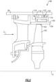
- Figures 4A-4D show a two-piece mandrel 300 according to an embodiment.
- the mandrel 300 has a tapered first portion 302 and a tapered second portion 304.
- the first portion 302 has an outer surface 306 and an inner surface 308.
- the second portion 304 has an outer surface 310 and an inner surface 312.
- each of the outer and inner surfaces 306, 310, 308, 312 is a radial surface.
- the outer surfaces 306, 310 are parallel to one another, and the inner surfaces 308, 312 are parallel to one another.
- the inner surfaces 308, 312 are offset relative to the outer surfaces 310, 312. That is, an axis of revolution of the outer surfaces 306, 310 is offset from an axis of revolution of the inner surfaces 308, 312.
- this offset may be approximated as an angle between a tangent of the inner surfaces 308, 312 and a tangent of the outer surfaces 306, 310 of between 1 and 10°.
- the first portion 302 and second portion 304 are opposing radial wedges. The offset axes of the radial inner and outer surfaces results in different heights at each end of each portion.
- the mandrel 300 has a first end 303 and a second end 305.
- the first portion 302 has a first height H 1 at the first end 303 and a second height Hz at the second end 305.
- the second portion 304 is flipped, meaning it has the first height H 1 at the second end 305 and the second height Hz at the first end 303.
- a difference between the first height H 1 and the second height H 2 is between about 0.005 inches (0.127 mm) and 0.100 inches (2.54 mm). In a further embodiment, the difference in height between the first height H 1 and the second height H 2 is about 0.020 inches (0.508 mm).
- the outer surfaces 306, 310 are shaped depending on the component they are used to form.
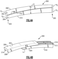
- the mandrel 300 When the first and second portions 302, 304 are in a retracted state, as shown in Figure 4A , the mandrel 300 has a constant cross section along the length. The mandrel 300 has a height H along the entire length. When the first and second portions 302, 304 are in an expanded state, as shown in Figure 4B , a height h is smaller than the height H. This smaller height h when the first and second portions 302, 304 are in the retracted state facilitates easy removal of the mandrel 300 from the component. The first and second portions 302 cannot slide beyond one another past the retracted state.
- the first and second portions 302, 304 each include dovetail surfaces 314, 316 along inner surfaces 308, 312, respectively.
- each of the first and second portions 302, 304 includes a pair of projections with at least one angled surface.
- the first portion 302 includes a pair of projections 318 along outside edges, with the dovetail surfaces 314 facing inward, or towards one another.
- the second portion 304 includes a pair of projections 320 inward of the outside edge, with the dovetail surfaces 316 facing outward, or away from one another.
- the pair of projections 320 fits inward of the pair of projections 318, while dovetail surfaces 314, 316 contact one another.
- the CMC component is formed around the mandrel 300, then the first and second portions 302, 304 are slid out opposing ends of the component.
- the opposing radial wedge shape of the first and second portions 302, 304 allows for a mandrel that is easier to remove, because it avoids being locked into the part.
- the first and second portions 302, 304 cannot slide past center in order to have a constant cross section.
- the dovetail surfaces provide self-centering of the first and second portions when locked for a more precisely controlled tool.
- the dovetail surfaces may produce a CMC part with more precisely controlled wall thicknesses.
- the mandrel 300 includes a channel 330.
- the ends of the mandrel 300 include a clearance hole 331 and angled surfaces 338.
- the channel 330 is generally circular in cross section, and the clearance hole 331 is generally rectangular.
- other shapes of the channel 330 and clearance hole 331 may be contemplated within the scope of this disclosure.
- the channel 330 receives a locking pin 332, as shown in Figures 5A and 5B .
- the locking pin 332 may be inserted into the channel 330 from either or both ends of the mandrel 300 when the mandrel 300 is in the retracted state. As shown, two locking pins 332 may be used with the mandrel 300.
- the locking pin 332 includes an elongate body 334 and a tab 336.
- the tab 336 improves handling during use.
- the elongate body 334 is generally cylindrical. In other embodiments, the elongate body 334 is generally rectangular or another shape. The elongate body 334 is shaped to fit into the channel 330, and the tabs 336 fit into the clearance hole 331.
- Figure 5B shows the pins 332 inserted into the channel 330.
- the first and second portions 302, 304 may have angled surfaces 338 adjacent the channel 330. These angled surfaces 338 engage with the tab 336 to force the first and second portions 302, 304 away from one another.
- a small gap 340 is formed between the inner surfaces 308, 312.
- the dovetail surfaces 314, 316 keep the first and second portions 302, 304 together while the pin 332 is inserted.
- the locking pins 332 are self-centering due to the dovetail surfaces 314, 316.
- the first and second portions 302, 304 are expanded outward, bringing the mandrel 300 to its maximum height. This makes the mandrel 300 easier to remove once the pin 332 is removed.
- the mandrel design does not require any threaded parts, making it easier to construct.
- the mandrel may be formed from graphite for use in high temperature furnaces.
- Figures 6A-6C show an alternate configuration utilizing a wedge style locking feature in place of the locking pin 332.
- the mandrel 400 has a rectangular channel 430.
- a locking wedge 432 is inserted into the channel 430 to force the dovetail surfaces 414, 416 into engagement and form the gap 440.
- the locking wedge 432 extends the full length of the mandrel 400.
- the locking wedge 432 is tapered, such that it has a smaller thickness at a first end 442 than at a second end 444.
- the locking wedge 432 is inserted into the mandrel 400 with the first end 442 first.
- the first and second portions 402, 404 are forced apart.
- the locking wedge 432 may be removed by pushing on the first end 442 or by pulling on the second end 444.
- the second end 444 may include a puller feature 446 to aid in pulling the locking wedge 432 from the channel 430.
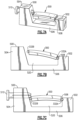
- Figures 7A-7C show a molding fixture that uses the mandrel 300.
- the mandrel 300 is mounted in a fixture 500.
- the fixture 500 has a first member 502 and a second member 504 extending from a base 506.
- the first member 502 includes a groove 508.
- the mandrel 300 with locking pins 332 inserted is mounted on the fixture 500.
- One of the pins 332A fits into the groove 508 and is maintained in place by the groove 508.
- the mandrel 300 is rotated about the pin 332A in the groove 508 such that the other pin 332B contacts the second member 504.
- a fixture locking pin 510 is inserted into the second member 504 to maintain the mandrel 300 in place.
- the fixture locking pin 510 is engaged with the locking pin 332B.
- the fixture locking pin 510 is held in place by a combination of friction and spring force.
- This mounting arrangement of the mandrel 300 in the fixture 500 provides clearance about the mandrel 300 to form the CMC plies of the component to be formed.
- the base 506 provides the outer mold line for the component. In such embodiments, the entire gap 520 between the mandrel 300 and base 506 will be filled with CMC plies to form the component.
- a method of forming a CMC component includes the steps of providing a mandrel 300 having first and second portions 302, 304 in a retracted state and inserting locking pins 332 into the ends of the mandrel 300 to lock the first and second portions in the retracted state.
- the mandrel may be mounted to a fixture 500.
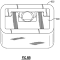
- a plurality of CMC laminate layers 601 are wrapped about the mandrel 300, as shown in Figures 8A-8B . After the CMC laminates 601 are wrapped about the mandrel 300, they are solidified into a component 602. In some embodiments, this includes injecting a resin into the fibers.
- the CMC laminates 601 may be silicon carbide fibers, formed into a woven fabric in each layer. The fibers may be coated by a boron nitride.
- the component is densified. Densification generally includes adding additional material to make the CMC laminates more stiff than their free woven fiber state. The densification process increases the density of the laminate material after assembly. A filler material, such as a silicon carbide matrix material, is injected into the spaces between the fibers in the woven layers.
- One hundred percent densification may be defined as the layers being completely saturated with the matrix and about the fibers.
- One hundred percent densification may be defined as the theoretical upper limit of layers being completely saturated with the matrix and about the fibers, such that no additional material may be deposited. In practice, 100% may be difficult to achieve in practice. The desired amount of densification depends on the particular application.
- the mandrel 300 and component 602 are removed from the fixture 500.
- the first and second portions 302, 304 of the mandrel 300 are moved to the expanded state.
- the component 602 is removed from the mandrel 300.
- the component may be a BOAS seal segment 105 (shown in Figures 3A-3B ), for example.
- the mandrel 300 may be used to form a CMC material, or may be used to form other matrix composite components, such as organic matrix composite (“OMC”) or polymer matrix composite (“PMC”) components.
- OMC organic matrix composite
- PMC polymer matrix composite
- the two-piece mandrel allows for a constant fully enclosed cross-section with no taper to be produced in a matrix composite plied component.
- the constant cross-section may further provide a stronger, more continuous ply construction and reduce the chance of having wrinkles or voids in the plies.
- the cross-section may also reduce any non-laminated zones, noodles, matrix, or chopped strands.
- the mandrel may further provide a more uniform hot wall thickness in thermal parts, such as a BOAS.
- the self-centering pins and dovetail surfaces ensure repeatable results in the manufacturing process.
- a rectangular cross-section mandrel is illustrated, the cross-section could be tubular or another shape.
Landscapes
- Engineering & Computer Science (AREA)
- Mechanical Engineering (AREA)
- Chemical & Material Sciences (AREA)
- General Engineering & Computer Science (AREA)
- Ceramic Engineering (AREA)
- Manufacturing & Machinery (AREA)
- Structural Engineering (AREA)
- Organic Chemistry (AREA)
- Materials Engineering (AREA)
- Inorganic Chemistry (AREA)
- Moulding By Coating Moulds (AREA)
- Moulds For Moulding Plastics Or The Like (AREA)
- Forging (AREA)
Abstract
Description
- This application relates to a mandrel having a constant cross-section for forming components from ceramic matrix composites.
- Gas turbine engines are known and typically include a compressor compressing air and delivering it into a combustor. The air is mixed with fuel in the combustor and ignited. Products of the combustion pass downstream over turbine rotors, driving them to rotate.
- It is desirable to ensure that the bulk of the products of combustion pass over turbine blades on the turbine rotor. As such, it is known to provide blade outer air seals radially outwardly of the blades. Blade outer air seals have been proposed made of ceramic matrix composite fiber layers.
- Some known methods of forming blade outer air seals of ceramic matrix composite fiber layers use a mandrel.
- According to a first aspect of the present invention there is provided a mandrel for a molding process that includes a first portion that has a first portion outer surface, a first portion inner surface, a first portion first end, and a first portion second end. A thickness of the first portion first end is greater than the first portion second end. A second portion has a second portion outer surface, a second portion inner surface, a second portion first end, and a second portion second end. A thickness of the second portion first end is smaller than the second portion second end. The first portion inner surface engages the second portion inner surface to form a mandrel that has a constant cross-section.
- In an embodiment of the above, a first protrusion has a first dovetail surface that extends from the first portion inner surface. A second protrusion has a second dovetail surface that extends from the second portion inner surface. The first and second dovetail surfaces abut one another.
- In a further embodiment of any of the above, a channel is formed between the first and second portions and extends along a length of the mandrel.
- In a further embodiment of any of the above, a locking pin is inserted into an end of the channel.
- In a further embodiment of any of the above, the locking pin is configured to contact the first and second portions and maintain a gap between the first and second portions along the length of the mandrel.
- In a further embodiment of any of the above, a second locking pin is inserted into a second end of the channel.
- In a further embodiment of any of the above, the end of the channel and the second end of the channel each have an angled surface for engagement with the locking pin and second locking pin.
- In a further embodiment of any of the above, a locking wedge is inserted into an end of the channel and configured to maintain a gap between the first and second portions along the length of the mandrel.
- In a further embodiment of any of the above, the first and second portions are formed from graphite.
- A molding apparatus according to another aspect of the present invention includes a fixture that has a first member and a second member that extend from a base. The first member has a groove and the second member has a fixture pin. A mandrel has a first portion and a second portion. Each of the first and second portion has a dovetail mating surface. The mandrel has first and second locking pins. The mandrel is secured to the fixture by the groove at the first member and by the fixture pin at the second member.
- In an embodiment of the above, the fixture pin contacts the second locking pin.
- In a further embodiment of any of the above, a space is formed between the mandrel and the base and is configured to receive ceramic matrix composite material when a component is formed about the mandrel.
- In a further embodiment of any of the above, the mandrel is configured to provide an inner mold surface and the base is configured to provide an outer mold surface for forming a component.
- In a further embodiment of any of the above, the mandrel is formed from graphite.
- In a further aspect of the present invention there is provided a method of forming a matrix composite component includes providing a mandrel that has a first portion and a second portion. The first portion includes a first dovetail surface in engagement with a second dovetail surface of the second portion. A locking pin is inserted into an end of the mandrel. A matrix composite laminate is wrapped about the mandrel to form a component. The locking pin is removed. The first portion is removed from a first end of the component and the second portion is removed from a second end of the component.
- In an embodiment of the above, the inserting the locking pin comprises forming and maintaining a gap between a first portion inner surface and a second portion inner surface.
- In a further embodiment of any of the above, the matrix composite laminate is densified before removing the locking pin.
- In a further embodiment of any of the above, the mandrel is mounted to a fixture before the wrapping of the matrix composite laminate.
- In a further embodiment of any of the above, the mandrel provides an inner mold surface and the fixture provides an outer mold surface for the matrix composite laminate.
- In a further embodiment of any of the above, the component is a blade outer air seal.
- These and other features may be best understood from the following drawings and specification.
-
-
Figure 1 schematically shows a gas turbine engine. -
Figure 2 shows a turbine section. -
Figure 3A shows an exemplary blade outer air seal. -
Figure 3B shows a cross-section of a blade outer air seal. -
Figure 4A shows an exemplary mandrel in a retracted state. -
Figure 4B shows an exemplary mandrel in an expanded state. -
Figure 4C shows an exemplary mandrel. -
Figure 4D shows a cross-section of an exemplary mandrel. -
Figure 5A shows an exploded view of an exemplary mandrel. -
Figure 5B shows a cross-section of an exemplary mandrel. -
Figure 6A shows another exemplary mandrel. -
Figure 6B shows a portion of another exemplary mandrel. -
Figure 6C shows an exemplary locking wedge. -
Figure 7A shows an exemplary fixture. -
Figure 7B shows an exemplary fixture. -
Figure 7C shows an exemplary fixture. -
Figure 8A shows an exemplary mandrel and component. -
Figure 8B shows an exemplary mandrel and component. -
Figure 1 schematically illustrates agas turbine engine 20. Thegas turbine engine 20 is disclosed herein as a two-spool turbofan that generally incorporates afan section 22, acompressor section 24, acombustor section 26 and aturbine section 28. Thefan section 22 drives air along a bypass flow path B in a bypass duct defined within anacelle 15, and also drives air along a core flow path C for compression and communication into thecombustor section 26 then expansion through theturbine section 28. Although depicted as a two-spool turbofan gas turbine engine in the disclosed non-limiting embodiment, it should be understood that the concepts described herein are not limited to use with two-spool turbofans as the teachings may be applied to other types of turbine engines including three-spool architectures. - The
exemplary engine 20 generally includes alow speed spool 30 and ahigh speed spool 32 mounted for rotation about an engine central longitudinal axis A relative to an enginestatic structure 36 viaseveral bearing systems 38. It should be understood that various bearingsystems 38 at various locations may alternatively or additionally be provided, and the location of bearingsystems 38 may be varied as appropriate to the application. - The
low speed spool 30 generally includes aninner shaft 40 that interconnects, a first (or low) pressure compressor 44 and a first (or low)pressure turbine 46. Theinner shaft 40 is connected to thefan 42 through a speed change mechanism, which in exemplarygas turbine engine 20 is illustrated as a gearedarchitecture 48 to drive afan 42 at a lower speed than thelow speed spool 30. Thehigh speed spool 32 includes anouter shaft 50 that interconnects a second (or high)pressure compressor 52 and a second (or high)pressure turbine 54. Acombustor 56 is arranged inexemplary gas turbine 20 between thehigh pressure compressor 52 and thehigh pressure turbine 54. Amid-turbine frame 57 of the enginestatic structure 36 may be arranged generally between thehigh pressure turbine 54 and thelow pressure turbine 46. Themid-turbine frame 57 furthersupports bearing systems 38 in theturbine section 28. Theinner shaft 40 and theouter shaft 50 are concentric and rotate via bearingsystems 38 about the engine central longitudinal axis A which is collinear with their longitudinal axes. - The core airflow is compressed by the low pressure compressor 44 then the
high pressure compressor 52, mixed and burned with fuel in thecombustor 56, then expanded over thehigh pressure turbine 54 andlow pressure turbine 46. Themid-turbine frame 57 includesairfoils 59 which are in the core airflow path C. Theturbines low speed spool 30 andhigh speed spool 32 in response to the expansion. It will be appreciated that each of the positions of thefan section 22,compressor section 24,combustor section 26,turbine section 28, and fandrive gear system 48 may be varied. For example,gear system 48 may be located aft of the low pressure compressor, or aft of thecombustor section 26 or even aft ofturbine section 28, andfan 42 may be positioned forward or aft of the location ofgear system 48. - The
engine 20 in one example is a high-bypass geared aircraft engine. In a further example, theengine 20 bypass ratio is greater than about six, with an example embodiment being greater than about ten, the gearedarchitecture 48 is an epicyclic gear train, such as a planetary gear system or other gear system, with a gear reduction ratio of greater than about 2.3 and thelow pressure turbine 46 has a pressure ratio that is greater than about five. In one disclosed embodiment, theengine 20 bypass ratio is greater than about ten, the fan diameter is significantly larger than that of the low pressure compressor 44, and thelow pressure turbine 46 has a pressure ratio that is greater than about five.Low pressure turbine 46 pressure ratio is pressure measured prior to inlet oflow pressure turbine 46 as related to the pressure at the outlet of thelow pressure turbine 46 prior to an exhaust nozzle. The gearedarchitecture 48 may be an epicycle gear train, such as a planetary gear system or other gear system, with a gear reduction ratio of greater than about 2.3:1 and less than about 5:1. It should be understood, however, that the above parameters are only exemplary of one embodiment of a geared architecture engine and that the present invention is applicable to other gas turbine engines including direct drive turbofans. - A significant amount of thrust is provided by the bypass flow B due to the high bypass ratio. The
fan section 22 of theengine 20 is designed for a particular flight condition -- typically cruise at about 0.8 Mach and about 35,000 feet (10,668 meters). The flight condition of 0.8 Mach and 35,000 ft (10,668 meters), with the engine at its best fuel consumption - also known as "bucket cruise Thrust Specific Fuel Consumption ('TSFC')" - is the industry standard parameter of lbm of fuel being burned divided by lbf of thrust the engine produces at that minimum point. "Low fan pressure ratio" is the pressure ratio across the fan blade alone, without a Fan Exit Guide Vane ("FEGV") system. The low fan pressure ratio as disclosed herein according to one non-limiting embodiment is less than about 1.45. "Low corrected fan tip speed" is the actual fan tip speed in ft/sec divided by an industry standard temperature correction of [(Tram °R) / (518.7 °R)]0.5(where °R = K x 9/5). The "Low corrected fan tip speed" as disclosed herein according to one non-limiting embodiment is less than about 1150 ft / second (350.5 meters/second). -
Figure 2 shows a portion of aturbine section 100, which may be incorporated into a gas turbine engine such as the one shown inFigure 1 . However, it should be understood that other sections of thegas turbine engine 20 or other gas turbine engines, and even gas turbine engines not having a fan section at all, could benefit from this disclosure. - A
turbine blade 102 has a radiallyouter tip 103 that is spaced from a blade outer air seal ("BOAS") 104. TheBOAS 104 may be made up of a plurality ofseal segments 105 that are circumferentially arranged in an annulus about the central axis A of theengine 20. TheBOAS seal segments 105 may be monolithic bodies that are formed of a high thermal-resistance, low-toughness material, such as a ceramic matrix composite ("CMC"). - The
BOAS 104 may be mounted to an engine case or structure, such as enginestatic structure 36 via anattachment block 110. Theengine structure 36 may extend for a full 360° about the engine axis A. Theengine structure 36 may have aforward hook 118 supporting aforward hook 116 of theattachment block 110. Theengine structure 36 may have anaft hook 122 supporting anaft hook 120 on theattachment block 110. In the illustrated embodiment, engine structure hooks 118, 122 face rearwardly, while the attachment block hooks 116, 120 face forwardly. It should be understood, however, that the arrangement of some or all of thehooks hooks hooks -
Figures 3A and 3B show an exemplaryBOAS seal segment 105 of aBOAS 104. TheBOAS seal segment 105 includes aleading edge 106 and a trailingedge 108. TheBOAS segment 105 includes aforward wall 111 and anaft wall 112 that extend radially outward from abase portion 114 to anouter wall 115. Thebase portion 114 extends between theleading edge 106 and the trailingedge 108 and defines a gas path on a radially inner side and a non-gas path on a radially outer side. Theouter wall 115 includes a generally constant thickness and constant position in the radial direction such that an outer surface of theouter wall 115 is planar. Theforward wall 111, theaft wall 112, theouter wall 115, and thebase portion 114 define apassage 117 for attachment to the attachment block 110 (shown inFigure 2 ). In this disclosure, forward, aft, upstream, downstream, axial, radial, or circumferential is in relation to the engine axis A unless stated otherwise. - The
BOAS 104 is formed of a ceramic matrix composite ("CMC") material. TheBOAS 104 is formed of a plurality of CMC laminates. The laminates may be silicon carbide fibers, formed into a woven fabric in each layer. The fibers may be coated by a boron nitride. - CMC components such as a
BOAS 104 are formed by laying fiber material, such as laminate sheets, in tooling, injecting a liquid resin into the tooling, and curing to form a solid composite component. The component may be densified by adding additional material to further stiffen the laminates. In some more complex components, pre-formed parts are further provided within the tooling before material is put into the tooling. For example, a mandrel may be used to occupy a cavity in the component to prevent material from flowing into the cavity. -
Figures 4A-4D show a two-piece mandrel 300 according to an embodiment. Themandrel 300 has a taperedfirst portion 302 and a taperedsecond portion 304. Thefirst portion 302 has anouter surface 306 and aninner surface 308. Thesecond portion 304 has anouter surface 310 and aninner surface 312. In an embodiment, each of the outer andinner surfaces outer surfaces inner surfaces inner surfaces outer surfaces outer surfaces inner surfaces inner surfaces outer surfaces first portion 302 andsecond portion 304 are opposing radial wedges. The offset axes of the radial inner and outer surfaces results in different heights at each end of each portion. Themandrel 300 has afirst end 303 and asecond end 305. Thefirst portion 302 has a first height H1 at thefirst end 303 and a second height Hz at thesecond end 305. Thesecond portion 304 is flipped, meaning it has the first height H1 at thesecond end 305 and the second height Hz at thefirst end 303. In one embodiment, a difference between the first height H1 and the second height H2 is between about 0.005 inches (0.127 mm) and 0.100 inches (2.54 mm). In a further embodiment, the difference in height between the first height H1 and the second height H2 is about 0.020 inches (0.508 mm). Theouter surfaces - When the first and
second portions Figure 4A , themandrel 300 has a constant cross section along the length. Themandrel 300 has a height H along the entire length. When the first andsecond portions Figure 4B , a height h is smaller than the height H. This smaller height h when the first andsecond portions mandrel 300 from the component. The first andsecond portions 302 cannot slide beyond one another past the retracted state. - As shown in
Figure 4B , theinner surfaces second portions inner surfaces second portions Figures 4C-4D , thefirst portion 302 includes a pair ofprojections 318 along outside edges, with the dovetail surfaces 314 facing inward, or towards one another. Thesecond portion 304 includes a pair ofprojections 320 inward of the outside edge, with the dovetail surfaces 316 facing outward, or away from one another. The pair ofprojections 320 fits inward of the pair ofprojections 318, while dovetail surfaces 314, 316 contact one another. Although a pair of projections on each portion is illustrated, a single projection may fall within the scope of this disclosure. - In use, the CMC component is formed around the
mandrel 300, then the first andsecond portions second portions second portions - As shown in
Figures 4C-4D , themandrel 300 includes achannel 330. The ends of themandrel 300 include aclearance hole 331 andangled surfaces 338. In the illustrated embodiment, thechannel 330 is generally circular in cross section, and theclearance hole 331 is generally rectangular. However other shapes of thechannel 330 andclearance hole 331 may be contemplated within the scope of this disclosure. - The
channel 330 receives alocking pin 332, as shown inFigures 5A and 5B . Thelocking pin 332 may be inserted into thechannel 330 from either or both ends of themandrel 300 when themandrel 300 is in the retracted state. As shown, two lockingpins 332 may be used with themandrel 300. Thelocking pin 332 includes anelongate body 334 and atab 336. Thetab 336 improves handling during use. In an embodiment, theelongate body 334 is generally cylindrical. In other embodiments, theelongate body 334 is generally rectangular or another shape. Theelongate body 334 is shaped to fit into thechannel 330, and thetabs 336 fit into theclearance hole 331. -
Figure 5B shows thepins 332 inserted into thechannel 330. The first andsecond portions surfaces 338 adjacent thechannel 330. Theseangled surfaces 338 engage with thetab 336 to force the first andsecond portions pin 332 is inserted, asmall gap 340 is formed between theinner surfaces second portions pin 332 is inserted. The locking pins 332 are self-centering due to the dovetail surfaces 314, 316. When the locking pins 332 are in place, the first andsecond portions mandrel 300 to its maximum height. This makes themandrel 300 easier to remove once thepin 332 is removed. - The mandrel design does not require any threaded parts, making it easier to construct. For example, the mandrel may be formed from graphite for use in high temperature furnaces.
-
Figures 6A-6C show an alternate configuration utilizing a wedge style locking feature in place of thelocking pin 332. In this embodiment, themandrel 400 has arectangular channel 430. A lockingwedge 432 is inserted into thechannel 430 to force the dovetail surfaces 414, 416 into engagement and form thegap 440. The lockingwedge 432 extends the full length of themandrel 400. The lockingwedge 432 is tapered, such that it has a smaller thickness at afirst end 442 than at asecond end 444. The lockingwedge 432 is inserted into themandrel 400 with thefirst end 442 first. As the lockingwedge 432 is pushed further into thechannel 430 and the thickness of the lockingwedge 432 increases, the first andsecond portions wedge 432 may be removed by pushing on thefirst end 442 or by pulling on thesecond end 444. Thesecond end 444 may include apuller feature 446 to aid in pulling the lockingwedge 432 from thechannel 430. -
Figures 7A-7C show a molding fixture that uses themandrel 300. Themandrel 300 is mounted in afixture 500. Thefixture 500 has afirst member 502 and asecond member 504 extending from abase 506. Thefirst member 502 includes agroove 508. Themandrel 300 with lockingpins 332 inserted is mounted on thefixture 500. One of thepins 332A fits into thegroove 508 and is maintained in place by thegroove 508. Themandrel 300 is rotated about thepin 332A in thegroove 508 such that theother pin 332B contacts thesecond member 504. Afixture locking pin 510 is inserted into thesecond member 504 to maintain themandrel 300 in place. Thefixture locking pin 510 is engaged with thelocking pin 332B. Thefixture locking pin 510 is held in place by a combination of friction and spring force. - This mounting arrangement of the
mandrel 300 in thefixture 500 provides clearance about themandrel 300 to form the CMC plies of the component to be formed. In some embodiments, thebase 506 provides the outer mold line for the component. In such embodiments, theentire gap 520 between themandrel 300 andbase 506 will be filled with CMC plies to form the component. Once the component is formed, themandrel 300 is removed from thefixture 500 by removing thefixture locking pin 510. - A method of forming a CMC component includes the steps of providing a
mandrel 300 having first andsecond portions mandrel 300 to lock the first and second portions in the retracted state. The mandrel may be mounted to afixture 500. A plurality of CMC laminate layers 601 are wrapped about themandrel 300, as shown inFigures 8A-8B . After the CMC laminates 601 are wrapped about themandrel 300, they are solidified into acomponent 602. In some embodiments, this includes injecting a resin into the fibers. The CMC laminates 601 may be silicon carbide fibers, formed into a woven fabric in each layer. The fibers may be coated by a boron nitride. - In some examples, the component is densified. Densification generally includes adding additional material to make the CMC laminates more stiff than their free woven fiber state. The densification process increases the density of the laminate material after assembly. A filler material, such as a silicon carbide matrix material, is injected into the spaces between the fibers in the woven layers.
- One hundred percent densification may be defined as the layers being completely saturated with the matrix and about the fibers. One hundred percent densification may be defined as the theoretical upper limit of layers being completely saturated with the matrix and about the fibers, such that no additional material may be deposited. In practice, 100% may be difficult to achieve in practice. The desired amount of densification depends on the particular application.
- After the
component 602 is formed and solidified, themandrel 300 andcomponent 602 are removed from thefixture 500. The first andsecond portions mandrel 300 are moved to the expanded state. Thecomponent 602 is removed from themandrel 300. The component may be a BOAS seal segment 105 (shown inFigures 3A-3B ), for example. Themandrel 300 may be used to form a CMC material, or may be used to form other matrix composite components, such as organic matrix composite ("OMC") or polymer matrix composite ("PMC") components. - Known mandrels require the component to have a taper to allow the mandrel to be pulled from the part once the curing process is complete. However, such tapers may make the components more complicated. For example, backside sealing of BOAS faces may be more difficult with a tapered surface. The two-piece mandrel allows for a constant fully enclosed cross-section with no taper to be produced in a matrix composite plied component. The constant cross-section may further provide a stronger, more continuous ply construction and reduce the chance of having wrinkles or voids in the plies. The cross-section may also reduce any non-laminated zones, noodles, matrix, or chopped strands. The mandrel may further provide a more uniform hot wall thickness in thermal parts, such as a BOAS. The self-centering pins and dovetail surfaces ensure repeatable results in the manufacturing process. Although a rectangular cross-section mandrel is illustrated, the cross-section could be tubular or another shape.
- Although an embodiment of this invention has been disclosed, a worker of ordinary skill in this art would recognize that certain modifications would come within the scope of this disclosure. For that reason, the following claims should be studied to determine the true scope and content of this disclosure.
Claims (10)
- A molding apparatus, comprising:a fixture (500) having a first member (502) and a second member (504) extending from a base (506), the first member (502) having a groove (508) and the second member (504) having a fixture pin (510); anda mandrel (300) having a first portion (302) and a second portion (304), each of the first and second portions (302, 304) having a dovetail mating surface (314, 316; 414, 416), and the mandrel (300) having first and second locking pins (332), wherein the mandrel (300) is secured to the fixture (500) by the groove (508) at the first member (502) and by the fixture pin (510) at the second member (504)
- The molding apparatus of claim 1, wherein the mandrel (300) is formed from graphite.
- The molding apparatus of claim 1 or 2, wherein the fixture pin (510) contacts the second locking pin (332).
- The molding apparatus of any of claims 1 to 3, wherein a space (520) is formed between the mandrel (300) and the base (506) configured to receive ceramic matrix composite material when a component (602, 105) is formed about the mandrel (300).
- The molding apparatus of any of claims 1 to 4, wherein the mandrel (300) is configured to provide an inner mold surface and the base (506) is configured to provide an outer mold surface for forming a or the component (602, 105).
- A method of forming a matrix composite component (602, 105), such as a blade outer air seal (106), the method comprising:providing a mandrel (300) having a first portion (302) and a second portion (304), wherein the first portion (302) includes a first dovetail surface (316) in engagement with a second dovetail surface (314) of the second portion (304);inserting a locking pin (332) into an end of the mandrel (300);wrapping a matrix composite laminate (601) about the mandrel (300) to form a component (602, 105);removing the locking pin (332); andremoving the first portion (302) from a first end of the component and removing the second portion (304) from a second end of the component.
- The method of claim 6, wherein the inserting the locking pin (332) comprises forming and maintaining a gap (340) between a first portion inner surface (312) and a second portion inner surface (308).
- The method of claim 6 or 7, wherein the matrix composite laminate (601) is densified before removing the locking pin (332).
- The method of any of claims 6 to 8, wherein the mandrel (300) is mounted to a fixture (500) before the wrapping of the matrix composite laminate (601)
- The method of claim 9, wherein the mandrel (300) provides an inner mold surface and the fixture (500) provides an outer mold surface for the matrix composite laminate (601).
Applications Claiming Priority (2)
| Application Number | Priority Date | Filing Date | Title |
|---|---|---|---|
| US16/139,141 US11400624B2 (en) | 2018-09-24 | 2018-09-24 | Constant cross section mandrel for CMC components |
| EP19199359.1A EP3626427B1 (en) | 2018-09-24 | 2019-09-24 | Constant cross section mandrel for cmc components |
Related Parent Applications (2)
| Application Number | Title | Priority Date | Filing Date |
|---|---|---|---|
| EP19199359.1A Division EP3626427B1 (en) | 2018-09-24 | 2019-09-24 | Constant cross section mandrel for cmc components |
| EP19199359.1A Division-Into EP3626427B1 (en) | 2018-09-24 | 2019-09-24 | Constant cross section mandrel for cmc components |
Publications (2)
| Publication Number | Publication Date |
|---|---|
| EP4219128A2 true EP4219128A2 (en) | 2023-08-02 |
| EP4219128A3 EP4219128A3 (en) | 2023-09-13 |
Family
ID=68066695
Family Applications (2)
| Application Number | Title | Priority Date | Filing Date |
|---|---|---|---|
| EP19199359.1A Active EP3626427B1 (en) | 2018-09-24 | 2019-09-24 | Constant cross section mandrel for cmc components |
| EP23159233.8A Pending EP4219128A3 (en) | 2018-09-24 | 2019-09-24 | Constant cross section mandrel for cmc components |
Family Applications Before (1)
| Application Number | Title | Priority Date | Filing Date |
|---|---|---|---|
| EP19199359.1A Active EP3626427B1 (en) | 2018-09-24 | 2019-09-24 | Constant cross section mandrel for cmc components |
Country Status (2)
| Country | Link |
|---|---|
| US (2) | US11400624B2 (en) |
| EP (2) | EP3626427B1 (en) |
Families Citing this family (6)
| Publication number | Priority date | Publication date | Assignee | Title |
|---|---|---|---|---|
| US10034519B2 (en) | 2016-06-16 | 2018-07-31 | Adidas Ag | UV curable lattice microstructure for footwear |
| US10934878B2 (en) * | 2018-12-05 | 2021-03-02 | Raytheon Technologies Corporation | CMC loop boas |
| US11359507B2 (en) * | 2019-09-26 | 2022-06-14 | Raytheon Technologies Corporation | Double box composite seal assembly with fiber density arrangement for gas turbine engine |
| US11352897B2 (en) * | 2019-09-26 | 2022-06-07 | Raytheon Technologies Corporation | Double box composite seal assembly for gas turbine engine |
| US11396814B2 (en) * | 2020-06-03 | 2022-07-26 | Raytheon Technologies Corporation | Multi-piece mandrel for CMC components |
| US11965430B1 (en) | 2023-09-11 | 2024-04-23 | Rtx Corporation | Flared mandrel and process for effective use in transition regions |
Family Cites Families (29)
| Publication number | Priority date | Publication date | Assignee | Title |
|---|---|---|---|---|
| US1284363A (en) * | 1917-05-02 | 1918-11-12 | Westinghouse Electric & Mfg Co | Process of making tubes. |
| US2902080A (en) * | 1953-11-04 | 1959-09-01 | Western Electric Co | Apparatus for twisting wave guides |
| FR2042016A5 (en) * | 1969-01-21 | 1971-02-05 | Goodrich Co B F | Plastic hoses |
| FR2177518A1 (en) | 1972-03-28 | 1973-11-09 | Nord Pas Calais Houilleres | Mandrel for grp tubing - allowing mfr and release of long pipe sections |
| US4381960A (en) * | 1981-12-28 | 1983-05-03 | United Technologies Corporation | Method of manufacturing a filament wound article |
| JPS59150715A (en) | 1983-02-16 | 1984-08-29 | Daiichi Gaiyaa Kk | Mold material |
| US4591400A (en) * | 1984-05-15 | 1986-05-27 | United Technologies Corporation | Method of forming a fiber reinforced composite article of a complex configuration |
| US7153125B2 (en) * | 2000-01-19 | 2006-12-26 | Rain Bird Corporation | Molded plastic elbow |
| US6655633B1 (en) * | 2000-01-21 | 2003-12-02 | W. Cullen Chapman, Jr. | Tubular members integrated to form a structure |
| DE10044626A1 (en) | 2000-09-09 | 2002-03-21 | Behr Gmbh & Co | Core making long cylindrical channels in injection molding, is formed by sections which can be slid axially relative to one another, reducing core cross section |
| US6783824B2 (en) * | 2001-01-25 | 2004-08-31 | Hyper-Therm High-Temperature Composites, Inc. | Actively-cooled fiber-reinforced ceramic matrix composite rocket propulsion thrust chamber and method of producing the same |
| US6622797B2 (en) * | 2001-10-24 | 2003-09-23 | Hydril Company | Apparatus and method to expand casing |
| GB0221220D0 (en) * | 2002-09-13 | 2002-10-23 | Weatherford Lamb | Expanding coupling |
| US8177262B2 (en) * | 2005-07-28 | 2012-05-15 | Hydril Company Lp | Mid-seal for expandable connections |
| US7549469B2 (en) * | 2006-06-06 | 2009-06-23 | Baker Hughes Incorporated | Adjustable swage |
| US20090152770A1 (en) * | 2007-08-07 | 2009-06-18 | Canon Virginia Inc. | Mechanically collapsible core for injection molding |
| US8033810B2 (en) * | 2009-06-17 | 2011-10-11 | Progressive Components International Corporation | Lock for core assembly for injection molding tool |
| FR2972123B1 (en) | 2011-03-02 | 2014-06-13 | Snecma | PROCESS FOR MANUFACTURING A MONOBLOC REVOLUTION METAL PIECE INCORPORATING A CERAMIC FIBER REINFORCEMENT |
| DE102012000564B4 (en) * | 2012-01-16 | 2015-02-19 | Airbus Operations Gmbh | Forming tool and method for the manufacture of an aerodynamically shaped aircraft component made of fiber-reinforced plastic |
| FR3017321B1 (en) * | 2014-02-13 | 2016-08-26 | Snecma | INJECTION MOLD CORE FOR MAKING A COMPOSITE MATERIAL PART HAVING A CLOSED HOUSING |
| ES2872401T3 (en) * | 2014-03-10 | 2021-11-02 | Siemens Gamesa Renewable Energy As | A method of manufacturing a rotor blade for a wind turbine |
| US10226899B2 (en) * | 2015-01-02 | 2019-03-12 | The Boeing Company | System and method of forming a component using a mandrel assembly |
| GB201513236D0 (en) | 2015-07-28 | 2015-09-09 | Rolls Royce Plc | A nozzle guide vane passage |
| DE102015221182A1 (en) * | 2015-10-29 | 2017-05-04 | Bayerische Motoren Werke Aktiengesellschaft | Core system, use of the core system in the manufacture of a fiber composite component and method for producing a fiber composite component |
| FR3044253B1 (en) * | 2015-11-26 | 2018-05-18 | Safran Aircraft Engines | MOLD FOR THE MANUFACTURE OF A GAS TURBINE BLOWER CASING IN COMPOSITE MATERIAL AND METHOD FOR CLOSING SUCH MOLD |
| US10167677B2 (en) * | 2016-04-29 | 2019-01-01 | William von Eberstein | Flotation system and method |
| US9908594B2 (en) * | 2016-04-29 | 2018-03-06 | Expert E&P Consultants, L.L.C. | Flotation system and method |
| DE102018116019A1 (en) * | 2018-07-02 | 2020-01-02 | Rolls-Royce Deutschland Ltd & Co Kg | Bearing device for load reduction |
| US11040915B2 (en) * | 2018-09-11 | 2021-06-22 | General Electric Company | Method of forming CMC component cooling cavities |
-
2018
- 2018-09-24 US US16/139,141 patent/US11400624B2/en active Active
-
2019
- 2019-09-24 EP EP19199359.1A patent/EP3626427B1/en active Active
- 2019-09-24 EP EP23159233.8A patent/EP4219128A3/en active Pending
-
2022
- 2022-07-06 US US17/858,287 patent/US20230100487A1/en active Pending
Also Published As
| Publication number | Publication date |
|---|---|
| EP3626427A2 (en) | 2020-03-25 |
| EP3626427B1 (en) | 2023-04-12 |
| EP4219128A3 (en) | 2023-09-13 |
| US20200094447A1 (en) | 2020-03-26 |
| US20230100487A1 (en) | 2023-03-30 |
| EP3626427A3 (en) | 2020-07-15 |
| US11400624B2 (en) | 2022-08-02 |
Similar Documents
| Publication | Publication Date | Title |
|---|---|---|
| US11400624B2 (en) | Constant cross section mandrel for CMC components | |
| EP3919248B1 (en) | Multi-piece mandrel for cmc components | |
| EP3626934A1 (en) | Turbine section comprising a featherseal formed of cmc material | |
| US11125096B2 (en) | CMC boas arrangement | |
| EP3663533B1 (en) | Method of forming a boas | |
| EP3719263A1 (en) | Blade outer air seal assembly with intersegment seal | |
| EP3613951B1 (en) | Blade outer air seal with circumferential hook assembly | |
| US11242991B2 (en) | CMC component arrangement and method of manufacture | |
| EP3767075A1 (en) | Assembly with blade outer air seal formed of ceramic matrix composite | |
| EP3722569A1 (en) | Blade outer air seal and turbine section | |
| EP3712382A2 (en) | Blade outer air seal with wear liner | |
| EP3767077B1 (en) | Cmc boas arrangement | |
| EP3736410B1 (en) | Nesting components | |
| EP3708786A2 (en) | Cmc boas with internal support structure | |
| EP3767076A1 (en) | Assembly with blade outer air seal formed of ceramic matrix composite | |
| EP3712384A1 (en) | Blade outer air seal with seal carrier | |
| EP3617459B1 (en) | Method of forming a gas turbine component formed of laminate | |
| EP3712383A1 (en) | Cmc blade outer air seal |
Legal Events
| Date | Code | Title | Description |
|---|---|---|---|
| PUAI | Public reference made under article 153(3) epc to a published international application that has entered the european phase |
Free format text: ORIGINAL CODE: 0009012 |
|
| STAA | Information on the status of an ep patent application or granted ep patent |
Free format text: STATUS: THE APPLICATION HAS BEEN PUBLISHED |
|
| AC | Divisional application: reference to earlier application |
Ref document number: 3626427 Country of ref document: EP Kind code of ref document: P |
|
| AK | Designated contracting states |
Kind code of ref document: A2 Designated state(s): AL AT BE BG CH CY CZ DE DK EE ES FI FR GB GR HR HU IE IS IT LI LT LU LV MC MK MT NL NO PL PT RO RS SE SI SK SM TR |
|
| PUAL | Search report despatched |
Free format text: ORIGINAL CODE: 0009013 |
|
| AK | Designated contracting states |
Kind code of ref document: A3 Designated state(s): AL AT BE BG CH CY CZ DE DK EE ES FI FR GB GR HR HU IE IS IT LI LT LU LV MC MK MT NL NO PL PT RO RS SE SI SK SM TR |
|
| RIC1 | Information provided on ipc code assigned before grant |
Ipc: B29C 70/04 20060101ALN20230809BHEP Ipc: B29C 33/48 20060101ALI20230809BHEP Ipc: B29C 53/82 20060101AFI20230809BHEP |
|
| RAP3 | Party data changed (applicant data changed or rights of an application transferred) |
Owner name: RTX CORPORATION |
|
| STAA | Information on the status of an ep patent application or granted ep patent |
Free format text: STATUS: REQUEST FOR EXAMINATION WAS MADE |
|
| 17P | Request for examination filed |
Effective date: 20231107 |
|
| RBV | Designated contracting states (corrected) |
Designated state(s): AL AT BE BG CH CY CZ DE DK EE ES FI FR GB GR HR HU IE IS IT LI LT LU LV MC MK MT NL NO PL PT RO RS SE SI SK SM TR |
|
| GRAP | Despatch of communication of intention to grant a patent |
Free format text: ORIGINAL CODE: EPIDOSNIGR1 |
|
| STAA | Information on the status of an ep patent application or granted ep patent |
Free format text: STATUS: GRANT OF PATENT IS INTENDED |