EP3255229B1 - Auxiliary locking device for sliding doors or hinged doors and the like for applications in motor vehicles - Google Patents
Auxiliary locking device for sliding doors or hinged doors and the like for applications in motor vehicles Download PDFInfo
- Publication number
- EP3255229B1 EP3255229B1 EP17174834.6A EP17174834A EP3255229B1 EP 3255229 B1 EP3255229 B1 EP 3255229B1 EP 17174834 A EP17174834 A EP 17174834A EP 3255229 B1 EP3255229 B1 EP 3255229B1
- Authority
- EP
- European Patent Office
- Prior art keywords
- locking device
- doors
- lock
- motor vehicles
- hook
- Prior art date
- Legal status (The legal status is an assumption and is not a legal conclusion. Google has not performed a legal analysis and makes no representation as to the accuracy of the status listed.)
- Active
Links
- 230000000284 resting effect Effects 0.000 claims description 8
- 238000003780 insertion Methods 0.000 claims description 5
- 230000037431 insertion Effects 0.000 claims description 5
- 229910000831 Steel Inorganic materials 0.000 claims description 3
- 239000010959 steel Substances 0.000 claims description 3
- 239000004809 Teflon Substances 0.000 description 3
- 229920006362 Teflon® Polymers 0.000 description 3
- 239000000428 dust Substances 0.000 description 3
- 239000000463 material Substances 0.000 description 2
- 239000012528 membrane Substances 0.000 description 2
- 239000007769 metal material Substances 0.000 description 2
- 230000004913 activation Effects 0.000 description 1
- 230000006978 adaptation Effects 0.000 description 1
- 230000006835 compression Effects 0.000 description 1
- 238000007906 compression Methods 0.000 description 1
- 230000001419 dependent effect Effects 0.000 description 1
- 238000005553 drilling Methods 0.000 description 1
- 238000004519 manufacturing process Methods 0.000 description 1
- 238000007254 oxidation reaction Methods 0.000 description 1
- 229920002050 silicone resin Polymers 0.000 description 1
- 239000007787 solid Substances 0.000 description 1
- 229910001220 stainless steel Inorganic materials 0.000 description 1
- 239000010935 stainless steel Substances 0.000 description 1
- 238000005496 tempering Methods 0.000 description 1
- XLYOFNOQVPJJNP-UHFFFAOYSA-N water Substances O XLYOFNOQVPJJNP-UHFFFAOYSA-N 0.000 description 1
Images


Classifications
-
- E—FIXED CONSTRUCTIONS
- E05—LOCKS; KEYS; WINDOW OR DOOR FITTINGS; SAFES
- E05B—LOCKS; ACCESSORIES THEREFOR; HANDCUFFS
- E05B83/00—Vehicle locks specially adapted for particular types of wing or vehicle
- E05B83/16—Locks for luggage compartments, car boot lids or car bonnets
- E05B83/26—Emergency opening means for persons trapped in the luggage compartment
-
- E—FIXED CONSTRUCTIONS
- E05—LOCKS; KEYS; WINDOW OR DOOR FITTINGS; SAFES
- E05B—LOCKS; ACCESSORIES THEREFOR; HANDCUFFS
- E05B63/00—Locks or fastenings with special structural characteristics
- E05B63/0004—Additional locks added to existing lock arrangements
-
- E—FIXED CONSTRUCTIONS
- E05—LOCKS; KEYS; WINDOW OR DOOR FITTINGS; SAFES
- E05B—LOCKS; ACCESSORIES THEREFOR; HANDCUFFS
- E05B63/00—Locks or fastenings with special structural characteristics
- E05B63/24—Arrangements in which the fastening members which engage one another are mounted respectively on the wing and the frame and are both movable, e.g. for release by moving either of them
- E05B63/244—Arrangements in which the fastening members which engage one another are mounted respectively on the wing and the frame and are both movable, e.g. for release by moving either of them the striker being movable for latching, the bolt for unlatching, or vice versa
- E05B63/246—Emergency release from inside by releasing the striker
-
- E—FIXED CONSTRUCTIONS
- E05—LOCKS; KEYS; WINDOW OR DOOR FITTINGS; SAFES
- E05B—LOCKS; ACCESSORIES THEREFOR; HANDCUFFS
- E05B83/00—Vehicle locks specially adapted for particular types of wing or vehicle
- E05B83/02—Locks for railway freight-cars, freight containers or the like; Locks for the cargo compartments of commercial lorries, trucks or vans
-
- E—FIXED CONSTRUCTIONS
- E05—LOCKS; KEYS; WINDOW OR DOOR FITTINGS; SAFES
- E05B—LOCKS; ACCESSORIES THEREFOR; HANDCUFFS
- E05B85/00—Details of vehicle locks not provided for in groups E05B77/00 - E05B83/00
- E05B85/02—Lock casings
-
- E—FIXED CONSTRUCTIONS
- E05—LOCKS; KEYS; WINDOW OR DOOR FITTINGS; SAFES
- E05B—LOCKS; ACCESSORIES THEREFOR; HANDCUFFS
- E05B85/00—Details of vehicle locks not provided for in groups E05B77/00 - E05B83/00
- E05B85/04—Strikers
-
- E—FIXED CONSTRUCTIONS
- E05—LOCKS; KEYS; WINDOW OR DOOR FITTINGS; SAFES
- E05B—LOCKS; ACCESSORIES THEREFOR; HANDCUFFS
- E05B85/00—Details of vehicle locks not provided for in groups E05B77/00 - E05B83/00
- E05B85/06—Lock cylinder arrangements
-
- E—FIXED CONSTRUCTIONS
- E05—LOCKS; KEYS; WINDOW OR DOOR FITTINGS; SAFES
- E05B—LOCKS; ACCESSORIES THEREFOR; HANDCUFFS
- E05B83/00—Vehicle locks specially adapted for particular types of wing or vehicle
- E05B83/02—Locks for railway freight-cars, freight containers or the like; Locks for the cargo compartments of commercial lorries, trucks or vans
- E05B83/12—Locks for railway freight-cars, freight containers or the like; Locks for the cargo compartments of commercial lorries, trucks or vans for back doors of vans
-
- E—FIXED CONSTRUCTIONS
- E05—LOCKS; KEYS; WINDOW OR DOOR FITTINGS; SAFES
- E05B—LOCKS; ACCESSORIES THEREFOR; HANDCUFFS
- E05B9/00—Lock casings or latch-mechanism casings ; Fastening locks or fasteners or parts thereof to the wing
- E05B9/08—Fastening locks or fasteners or parts thereof, e.g. the casings of latch-bolt locks or cylinder locks to the wing
- E05B9/084—Fastening of lock cylinders, plugs or cores
Definitions
- the present invention relates to a locking device of sliding or hinged doors and the like, for applications in motor vehicles.
- the invention relates to a locking device of cargo doors of a commercial motor vehicle that can be used to prevent the unauthorized opening thereof, in addition to the standard lock.
- the cargo doors for accessing the loading receptacles of the motor vehicle comprise standard locks which in many cases are easy to force open, thus not being suitable for preventing unauthorized access to the loading receptacles.
- a locking device for doors typically consists of a lock which comprises, inside a casing, a corresponding mechanism operable by a key that can be inserted into a keyhole arranged on the lock.
- a mechanism comprises a traditional lock which allows the activation of a bolt.
- Such a known lock of the locking device is configured to mechanically act in conjunction with a locking element of the bolt, which is separate from the lock, to ensure the closing of the door.
- both the lock and such a locking element of the bolt are each fixed on a respective leaf of the door by means of fixing means so that when the leaves are in the closed position, the bolt of the lock can be inserted into a seat of the locking elements, for example by operating the key. Thereby, any relative movement between the lock and the locking element of the bolt are prevented, thus ensuring that the door remains closed.
- Such a known door locking device using a bolt has the drawback of always requiring a key to control the insertion of the bolt into the seat of the locking element and to lock the door in closed position.
- Document EP2995754 A1 discloses an auxiliary device for opening and closing the loading compartment of a motor vehicle, which can be installed on the back door of the vehicle.
- Document ES1076172 U discloses a closing for a delivery vehicle.
- the object of the present invention is to propose a locking device of sliding or hinged doors and the like, for applications in motor vehicles, in particular in commercial motor vehicles, which allows the drawbacks indicated above with reference to the known art described to be overcome.
- a further task of the invention is to provide a locking device for the doors of a motor vehicle comprising contrivances which make it particularly suitable for resisting attempts of forced entry.
- a further task of the invention is to provide a locking device for the doors of a motor vehicle configured to accommodate different types of lock cylinders to meet different needs of use, including at least one suitable for performing the function of "hold open”.
- a locking device for doors of motor vehicles in particular sliding doors or hinged doors, according to the invention is indicated as a whole with numeral 100.
- the door locking device of the invention can be used in particular to lock the cargo doors of a commercial motor vehicle under closed conditions, in addition to a standard lock, thus preventing the unauthorized opening of such cargo doors and access to the loading receptacle of the motor vehicle.
- locking device 100 for doors of motor vehicles will also be indicated as locking device or more simply as device.
- the door locking device 100 comprises a lock 10 adapted to be fixed to a first leaf element 50 of the door.
- a lock 10 consists of a casing 1 for accommodating a lock unit 2 which is operable by a key (not shown) that can be inserted into a keyhole 2a prepared in casing 1.
- Such a casing 1 is hemispherical- or cap-shaped with a circular base portion 1a.
- a casing 1 is made of metal material, preferably steel with heat tempering processing to reach a specific degree of hardness HRC 52-54. It is worth noting that due to the cap shape of casing 1 and to the material used to make it, the locking device 100 of the invention ensures an increased resistance to attempts of forced entry both with sharp bodies and with cutting and drilling equipment.
- the above-mentioned lock unit 2 of the locking device 100 is accommodated in casing 1 along a first axis Z (shown with a dotted line in the drawings) which is orthogonal to a base 4 for fixing lock 10 to the first leaf element 50 of the door.
- a lock unit 2 is operable to control a disc element 3 for opening/closing the locking device 100 and is positioned coaxial to said lock unit 2 to rotate between an open position and a closed position of the device, and vice versa.
- the opening/closing disc element 3 operates as a rotating lock bolt of the locking device 100 of the invention.
- Such a disc element 3 radially extends from the first axis Z and comprises a through hole 3a for the insertion of an actuation end 11' of a cylinder unit 11 or first cylinder unit of the lock unit 2.
- the disc element 3 comprises a first arc-shaped engagement surface 3b and a first 3c and a second 3d protruding tooth operating as end stop elements in the rotation of the disc element 3, as will be clarified below.
- the aforesaid lock unit 2 comprises a first 12 and a second 13 portion of container/adapter of the cylinder unit 11 both having a substantially circular section.
- Such first 12 and second 13 container portion may be coupled with each other to accommodate the cylinder unit 11 itself, thus forming a first adapter 12-13.
- a toroidal-shaped gasket 14 for example made of Teflon, is interposed between the second container portion 13 of the cylinder unit and the disc element 3.
- a further gasket 14' is interposed between the cylinder unit 11 and the disc element 3.
- the lock unit 2 comprises protection elements 15, 16, 17 of the cylinder unit 11 interposed between keyhole 2a and the first container portion 12 of the cylinder unit.
- protection elements of type known to a person skilled in the art, materialize in a defender element 15 and in dust covers 17 operable by springs (not shown) to interact with a respective cover 16.
- dust covers which may be applied on certain types of lock cylinders, have the advantage of avoiding foreign bodies (e.g. dust, water, etc.) from getting inside cylinder 11 once the key is extracted from the lock, thus compromising the correct operation thereof.
- the fixing base 4 of lock 10 includes a base sheet 6 fixed to casing 1 by means of first screws 7, in particular four screws. Such a base sheet 6 overlaps and is restrained to an undercut plate 5, which in turn may be fixed to the first leaf element 50 of the door of the motor vehicle by means of second screws 9. Respective third screws 8, in particular two screws, can be inserted into through holes 5a, 6a of the undercut plate 5 and of the base sheet 6, respectively, to ensure a solid fixing of lock 10 to the door of the motor vehicle.
- the locking device 100 of the invention further comprises a locking element 20 of the disc element 3, configured to be fixed to a second leaf element 51 of the door of the motor vehicle.
- Such a locking element 20 is configured to mechanically act in conjunction with the disc element 3 of lock 10 when the door is in a closed configuration, as shown in figure 2 .
- the locking element 20 is inserted in a respective compartment 19 prepared in the hemispherical casing 1 of lock 10.
- the locking element 20 comprises an engagement unit 21 shaped to delimit a seat 22 adapted to be engaged with the disc element 3 in closed position to prevent any relative movement between lock 10 and the locking element 20 in the closed configuration of the door.
- the engagement unit of the locking element 20 comprises a hook 21 which is rotatable about a second axis Y orthogonal to the first axis Z of casing 1, from a resting position to a disengaged position. In such a disengaged position, shown in figure 4 , hook 21 disengages the disc element 3 by opening the locking device 100 under emergency condition.
- the locking element 20 comprises manually-operated means 23 configured to operate the rotation of hook 21 about the second axis Y, from the resting position to the disengaged position to release the locking device 100 without using a key.
- such means for operating the rotation of hook 21 consist of a cable 24, for example made of steel, having a first end 24a fixed to a head portion 25 of hook 21 and a second free end 24b which is manually operable from inside the motor vehicle under the emergency condition.
- the locking element 20 comprises elastic means 26, for example one or more springs, associated with hook 21.
- elastic means 26 are configured to elastically rotate hook 21 from the disengaged position to the resting position following the ceasing of the action executed with the manually-operated means.
- the aforesaid elastic means 26 materialize in a torsion spring or a compression spring.
- the head portion 25 of hook 21 of the locking element 20 comprises a tilted contact and sliding surface 27 adapted to be engaged by the corresponding engagement surface 3b of the disc element 3 rotated in closed position.
- the engagement of the first surface 3b of the disc element 3 on the tilted surface 27 of hook 21 causes the rotation of hook 21 itself from the resting position, contrasting the action of the elastic means 26, away from the disc itself. Such a rotation is sufficient to engage the disc element 3 in the seat 22 of hook 21 to lock the door in closed position ( figure 2 ).
- the key may only be extracted from the cylinder unit 11 in the locked position of device 100.
- the rotatable hook 21 is fixed, for example by means of a pin 35, to a semi-circular plate 28 for fixing the .locking element 20 to the second leaf element 51 of the door.
- a plate 28 comprises parallel ribs 37 for the insertion of the pin 35 of hook 21 adapted to act in conjunction with a closing element 36 to delimit a rotation compartment 38 for hook 21. It is worth noting that plate 28 and the closing element 36 simultaneously may be fixed to each other and to the second leaf element 52 of the door by means of bolts 39 (shown in figure 1 ).
- the fixing plate 28 includes first 29 and second 30 security means adapted to hinder attempts to tamper with the device and/or unauthorized opening.
- the first security means comprise ribs 29 arranged on a circumferential portion of the fixing plate 28 for the protection of hook 21.
- the second security means comprise a tubular conduit 30 made in one piece with the fixing plate 28 and which extends from said fixing plate away from hook 21.
- a tubular conduit 30 which is in communication with the rotation compartment 38 of hook 21, is configured to promote the insertion and the protection of the release cable 24 in an emergency of device 100 ( figure 7 ).
- Such security means 29, 30 make it difficult to reach both hook 21 and the security cable 24 from the outside of device 100 in order to operate the hook in an emergency and therefore they hinder all attempts to force open and release device 100.
- cap-shaped casing 1 of device 100 is shaped so as to accommodate various types of cylinder units with the related containers or adapters.
- lock unit 2 in figure 1 comprises the first cylinder unit 11 which is operable by a flat key (not depicted).
- FIG 8 shows a perspective and exploded view of a second example embodiment of the key-operated lock unit 2' that can be used in the locking device 100 of the invention.
- a second lock unit 2' comprises a respective cylinder unit 111 or second cylinder unit which is operable by a tubular key 112 to act on a control element 115 of the lock unit 2'.
- Such a second cylinder unit 111 can be inserted into a second container or adapter 113 to be accommodated in casing 1.
- a respective toroidal-shaped gasket 114 is interposed between the second container/adapter 113 of the second cylinder unit and the disc element 3'.
- a head gasket 114a is positioned close to an opening 113a for inserting the second cylinder unit 111 into the second adapter 113.
- the control element 115 comprises an actuation end 115' which can be inserted into the through hole 3a of the disc element 3'. It is worth noting that the disc element 3' comprises the first engagement surface 3b similar to the one of disc 3 in figure 1 , but does not have protruding end stop teeth.
- the device 100 of the invention advantageously implements the function of "hold open", known to a person skilled in the art. With such a function, the key may be extracted both in closed lock position and in open lock position in order to meet various needs of use. In other words, the disc element 3' may be locked in open position and key 112 may be extracted from cylinder 111.
- Figure 9 shows a perspective and exploded view of a third example embodiment of the key-operated lock unit 2" that can be used in the locking device 100 of the invention.
- Such a third lock unit 2" comprises a third cylinder unit 211, in particular a double cylinder, which is operable by a key (not shown).
- a double cylinder 211 has an actuation end 211' which can be inserted into the through hole 3a of the disc element 3.
- Such a disc element 3 is similar to the one described with reference to figure 1 .
- Such a double cylinder 211 can be inserted into a respective container/adapter 213 or third adapter having U-shaped cross section to be accommodated in casing 1.
- a respective U-shaped gasket 214 for example made of Teflon, is interposed between the third container/adapter 213 of the cylinder and the disc element 3.
- a unit 215 for protecting the double cylinder 211 comprises a defender 215a fixed to a cover 215b between which a membrane 215c, for example a silicone resin membrane, and a respective head gasket 214a are interposed.
- a membrane 215c for example a silicone resin membrane
- cap-shaped casing 1 configured to accommodate the various above-mentioned lock units 2, 2', 2" is described in greater detail.
- casing 1 comprises a through hole 80 in communication with keyhole 2a and configured to accommodate the three types of lock units 2, 2', 2", that is the first 11, the second 111 and the third 211 cylinder unit inserted in the first 12-13, in the second 113 and in the third 213 container/adapter, respectively.
- the hole 80 is delimited by a first wall 81 connected to an inner wall 82 of casing 1 through radial ribs 83.
- the aforesaid first wall 81 of hole 80 comprises canals 84, in particular four canals, which are coaxial to the aforesaid hole 80.
- Such canals 84 are configured to engage longitudinal ribs 85 prepared on an outer surface S, S', S'' of the first 12-13, of the second 113 and of the third 213 adapter, respectively.
- longitudinal ribs 85 allow to insert and keep in position the first adapter 12-13 of the first cylinder 11 (shown in figure 1 ) in hole 80.
- the through hole 80 comprises a first 86 and a second 87 compartment which radially extend from the aforesaid hole 80 along a same main direction or first direction and in opposite direction.
- the above-mentioned second adapter element 113 of the second cylinder unit 111 comprises a protruding portion 88, with a rectangular cross section, prepared on the outer surface S' of such a second adapter element and configured to be housed in the first compartment 86.
- providing such a first compartment 86 advantageously allows to insert and keep in position the second adapter element 113 of the second cylinder 111 in the hole 80 of casing 1.
- the third locking cylinder 211 of the above-described lock unit 2" housed in the third adapter element 213 comprises a first protruding portion 89 configured to be housed in the second compartment 87.
- providing such a second compartment 87 advantageously allows to insert and keep in position the third cylinder 211, with the related adapter 213, in the hole 80 of casing 1.
- one of the above-mentioned radial ribs 83 of casing 1 comprises a raised element 90 configured to abut with the protruding teeth 3c and 3d of the disc element 3 by acting as end stop for the rotation of such a disc element.
- all the components of the locking element 20 of the locking device 100 and all the fixing means used in the device are made of metal material, preferably o.f stainless steel, to ensure an increased resistance to oxidization.
- defender 15, 215a of the cylinder unit 11, 211 has the same features as the cap-shaped casing 1 in terms of materials used for the manufacturing thereof.
- the locking device 100 for doors of motor vehicles of the invention has several advantages with respect to known solutions and perfectly achieves the set objects.
- the locking device 100 there is no need to use the key to lock the door in closed position. Indeed, following the movement of the first leaf element 50 to bring the door of the motor vehicle to the closed position, due to the shape of the head portion 25 of the rotatable hook 21, the disc element 3, which is already in closed position, engages the contact and sliding surface 27 of such a head portion 25, thus causing the rotation of hook 21 away from the disc itself. Such a rotation is sufficient to engage the disc in seat 22 of the hook to lock the door in closed position. Moreover, with the device of the invention, there is no need to use a mechanism with a "quick release" movement.
- the locking device 100 for doors of motor vehicles of the invention does not have the drawbacks for making and implementing emergency opening systems of the door since such systems in device 100 are associated with the locking element 20 and not with the lock 10.
- the locking device 100 of the doors of a motor vehicle comprises security means associated with the locking element 20 which prevent the opening of the device with skill, for example by introducing foreign bodies to cause a rotation of hook 21.
- security means therefore make the door locking device 100 of the invention suitable for resisting attempts of forced entry and tampering.
- device 100 is configured to accommodate different types of lock cylinders to meet different needs of use, among them one suitable for performing the function of "hold open".
Description
- The present invention relates to a locking device of sliding or hinged doors and the like, for applications in motor vehicles. In greater detail, the invention relates to a locking device of cargo doors of a commercial motor vehicle that can be used to prevent the unauthorized opening thereof, in addition to the standard lock.
- In the field of commercial motor vehicles, whether they are sliding or hinged, the cargo doors for accessing the loading receptacles of the motor vehicle comprise standard locks which in many cases are easy to force open, thus not being suitable for preventing unauthorized access to the loading receptacles.
- Nowadays, various types of devices or locks for locking the cargo doors of commercial motor vehicles are very common. Such known locking devices may be purchased separately to be fixed to the cargo doors of the motor vehicles, in addition to standard locks.
- A locking device for doors, for example hinged or sliding doors, for commercial motor vehicles of known type typically consists of a lock which comprises, inside a casing, a corresponding mechanism operable by a key that can be inserted into a keyhole arranged on the lock. Such a mechanism comprises a traditional lock which allows the activation of a bolt.
- Such a known lock of the locking device is configured to mechanically act in conjunction with a locking element of the bolt, which is separate from the lock, to ensure the closing of the door. In particular, both the lock and such a locking element of the bolt are each fixed on a respective leaf of the door by means of fixing means so that when the leaves are in the closed position, the bolt of the lock can be inserted into a seat of the locking elements, for example by operating the key. Thereby, any relative movement between the lock and the locking element of the bolt are prevented, thus ensuring that the door remains closed.
- Such a known door locking device using a bolt has the drawback of always requiring a key to control the insertion of the bolt into the seat of the locking element and to lock the door in closed position.
- Moreover, since the movable bolt is included in the lock of the locking device, known systems adapted to release the device from the inside of the motor vehicle under emergency conditions and to allow the opening of the door are usually associated with the lock because they are configured to act on the bolt to release it. This causes certain drawbacks for making and implementing such emergency opening systems of the door since the lock of the device is usually fixed on the leaf of the door which is opened most often. Indeed, the case may occur in which the emergency opening mechanism of the cargo door of the motor vehicle, and particularly of sliding type, may get caught or otherwise interfere with the fixed portion of the lock applied.
- Document
EP2995754 A1 discloses an auxiliary device for opening and closing the loading compartment of a motor vehicle, which can be installed on the back door of the vehicle. DocumentES1076172 U - The object of the present invention is to propose a locking device of sliding or hinged doors and the like, for applications in motor vehicles, in particular in commercial motor vehicles, which allows the drawbacks indicated above with reference to the known art described to be overcome.
- A further task of the invention is to provide a locking device for the doors of a motor vehicle comprising contrivances which make it particularly suitable for resisting attempts of forced entry.
- A further task of the invention is to provide a locking device for the doors of a motor vehicle configured to accommodate different types of lock cylinders to meet different needs of use, including at least one suitable for performing the function of "hold open".
- Such objects and tasks are achieved by a locking device for doors of motor vehicles, particularly for sliding doors or hinged doors, as defined by appended
claim 1. - Preferred embodiments of such a door locking device are defined by the dependent claims.
- Further features and advantages of the sliding or hinged door locking device according to the invention will become apparent from the following description of preferred embodiments thereof, given only by way of nonlimiting, indicative example, with reference to the accompanying drawings, in which:
-
figure 1 shows a perspective and exploded view of the door locking device of the invention, comprising a first example embodiment of key-operated lock; -
figure 2 shows a sectional view of the locking device infigure 1 , fixed to the door with a disc element for the controlled opening/closing of the lock in closed position; -
figure 3 shows a sectional view of the locking device infigure 1 , fixed to the door with a disc element for the controlled opening/closing of the lock in open position; -
figure 4 shows a sectional view of the locking device infigure 1 , fixed to the door with a disc element for the controlled opening/closing of the lock in closed position and with a hook of the locking element of the opening/closing disc in open emergency position; -
figure 5 shows a sectional top view, and with parts separated, of the locking device infigure 1 , comprising a lock fixed to a first leaf element of the hinged door and a respective locking element fixed to a second leaf element of the door; -
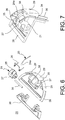
figure 6 shows an exploded and enlarged view of the locking element of the locking device of the invention; -
figure 7 shows a sectional view in assembled configuration, of the locking element infigure 6 ; -
figure 8 shows a perspective and exploded view of a second example embodiment of the key-operated lock that can be used in the locking device of the invention; -
figure 9 shows a perspective and exploded view of a third example embodiment of the key-operated lock that can be used in the locking device of the invention; -
figure 10 shows a bottom enlarged view of a casing for accommodating a lock unit of the locking device infigure 1 . - With reference to the aforesaid
figures 1 to 7 , a locking device for doors of motor vehicles, in particular sliding doors or hinged doors, according to the invention is indicated as a whole withnumeral 100. - The door locking device of the invention can be used in particular to lock the cargo doors of a commercial motor vehicle under closed conditions, in addition to a standard lock, thus preventing the unauthorized opening of such cargo doors and access to the loading receptacle of the motor vehicle.
- Later in the description, the
locking device 100 for doors of motor vehicles will also be indicated as locking device or more simply as device. - With reference to the drawings, the
door locking device 100 comprises alock 10 adapted to be fixed to afirst leaf element 50 of the door. Such alock 10 consists of acasing 1 for accommodating alock unit 2 which is operable by a key (not shown) that can be inserted into akeyhole 2a prepared incasing 1. - Such a
casing 1 is hemispherical- or cap-shaped with acircular base portion 1a. Such acasing 1 is made of metal material, preferably steel with heat tempering processing to reach a specific degree of hardness HRC 52-54. It is worth noting that due to the cap shape ofcasing 1 and to the material used to make it, thelocking device 100 of the invention ensures an increased resistance to attempts of forced entry both with sharp bodies and with cutting and drilling equipment. - With reference to
figures 2 to 3 , the above-mentionedlock unit 2 of thelocking device 100 is accommodated incasing 1 along a first axis Z (shown with a dotted line in the drawings) which is orthogonal to abase 4 forfixing lock 10 to thefirst leaf element 50 of the door. Such alock unit 2 is operable to control adisc element 3 for opening/closing thelocking device 100 and is positioned coaxial to saidlock unit 2 to rotate between an open position and a closed position of the device, and vice versa. In other words, the opening/closing disc element 3 operates as a rotating lock bolt of thelocking device 100 of the invention. Such adisc element 3 radially extends from the first axis Z and comprises a throughhole 3a for the insertion of an actuation end 11' of acylinder unit 11 or first cylinder unit of thelock unit 2. - In one example embodiment, the
disc element 3 comprises a first arc-shaped engagement surface 3b and a first 3c and a second 3d protruding tooth operating as end stop elements in the rotation of thedisc element 3, as will be clarified below. - In a first embodiment, the
aforesaid lock unit 2 comprises a first 12 and a second 13 portion of container/adapter of thecylinder unit 11 both having a substantially circular section. Such first 12 and second 13 container portion may be coupled with each other to accommodate thecylinder unit 11 itself, thus forming a first adapter 12-13. - Moreover, a toroidal-
shaped gasket 14, for example made of Teflon, is interposed between thesecond container portion 13 of the cylinder unit and thedisc element 3. - A further gasket 14' is interposed between the
cylinder unit 11 and thedisc element 3. - Moreover, the
lock unit 2 comprisesprotection elements cylinder unit 11 interposed betweenkeyhole 2a and the first container portion 12 of the cylinder unit. Such protection elements, of type known to a person skilled in the art, materialize in adefender element 15 and in dust covers 17 operable by springs (not shown) to interact with arespective cover 16. As is known, dust covers, which may be applied on certain types of lock cylinders, have the advantage of avoiding foreign bodies (e.g. dust, water, etc.) from getting insidecylinder 11 once the key is extracted from the lock, thus compromising the correct operation thereof. - Moreover, with reference to
figure 1 , thefixing base 4 oflock 10 includes abase sheet 6 fixed tocasing 1 by means offirst screws 7, in particular four screws. Such abase sheet 6 overlaps and is restrained to anundercut plate 5, which in turn may be fixed to thefirst leaf element 50 of the door of the motor vehicle by means ofsecond screws 9. Respectivethird screws 8, in particular two screws, can be inserted into throughholes undercut plate 5 and of thebase sheet 6, respectively, to ensure a solid fixing oflock 10 to the door of the motor vehicle. - The
locking device 100 of the invention further comprises alocking element 20 of thedisc element 3, configured to be fixed to asecond leaf element 51 of the door of the motor vehicle. - Such a
locking element 20 is configured to mechanically act in conjunction with thedisc element 3 oflock 10 when the door is in a closed configuration, as shown infigure 2 . In such a closed configuration of the door, thelocking element 20 is inserted in arespective compartment 19 prepared in thehemispherical casing 1 oflock 10. - In particular, the
locking element 20 comprises anengagement unit 21 shaped to delimit aseat 22 adapted to be engaged with thedisc element 3 in closed position to prevent any relative movement betweenlock 10 and thelocking element 20 in the closed configuration of the door. - In a preferred embodiment, the engagement unit of the locking
element 20 comprises ahook 21 which is rotatable about a second axis Y orthogonal to the first axis Z ofcasing 1, from a resting position to a disengaged position. In such a disengaged position, shown infigure 4 ,hook 21 disengages thedisc element 3 by opening thelocking device 100 under emergency condition. - Advantageously, with reference to
figures 2 to 4 , the lockingelement 20 comprises manually-operated means 23 configured to operate the rotation ofhook 21 about the second axis Y, from the resting position to the disengaged position to release thelocking device 100 without using a key. - In greater detail, such means for operating the rotation of
hook 21 consist of acable 24, for example made of steel, having afirst end 24a fixed to ahead portion 25 ofhook 21 and a secondfree end 24b which is manually operable from inside the motor vehicle under the emergency condition. - In addition, with reference to
figure 6 , the lockingelement 20 comprises elastic means 26, for example one or more springs, associated withhook 21. Such elastic means 26 are configured to elastically rotatehook 21 from the disengaged position to the resting position following the ceasing of the action executed with the manually-operated means.
For example, the aforesaid elastic means 26 materialize in a torsion spring or a compression spring. - In a preferred embodiment, the
head portion 25 ofhook 21 of the lockingelement 20 comprises a tilted contact and slidingsurface 27 adapted to be engaged by the correspondingengagement surface 3b of thedisc element 3 rotated in closed position. In particular, the engagement of thefirst surface 3b of thedisc element 3 on the tiltedsurface 27 ofhook 21 causes the rotation ofhook 21 itself from the resting position, contrasting the action of the elastic means 26, away from the disc itself. Such a rotation is sufficient to engage thedisc element 3 in theseat 22 ofhook 21 to lock the door in closed position (figure 2 ). - In order to release
device 100 and open the door from such a closed position of the door, there is a need to rotate the disc element, by means of a key, by 90°, from the closed position to the open position (figure 3 ) to bringdevice 100 from the locked configuration to the released configuration. - Generally, the key may only be extracted from the
cylinder unit 11 in the locked position ofdevice 100. - In a preferred embodiment, with reference to
figures 1 ,6 and 7 , therotatable hook 21 is fixed, for example by means of apin 35, to asemi-circular plate 28 for fixing the .lockingelement 20 to thesecond leaf element 51 of the door. - It is worth noting that such a
plate 28 comprisesparallel ribs 37 for the insertion of thepin 35 ofhook 21 adapted to act in conjunction with aclosing element 36 to delimit arotation compartment 38 forhook 21. It is worth noting thatplate 28 and theclosing element 36 simultaneously may be fixed to each other and to the second leaf element 52 of the door by means of bolts 39 (shown infigure 1 ). - Advantageously, the fixing
plate 28 includes first 29 and second 30 security means adapted to hinder attempts to tamper with the device and/or unauthorized opening. - In particular, the first security means comprise
ribs 29 arranged on a circumferential portion of the fixingplate 28 for the protection ofhook 21. - The second security means comprise a
tubular conduit 30 made in one piece with the fixingplate 28 and which extends from said fixing plate away fromhook 21. Such atubular conduit 30, which is in communication with therotation compartment 38 ofhook 21, is configured to promote the insertion and the protection of therelease cable 24 in an emergency of device 100 (figure 7 ). - Such security means 29, 30 make it difficult to reach both
hook 21 and thesecurity cable 24 from the outside ofdevice 100 in order to operate the hook in an emergency and therefore they hinder all attempts to force open andrelease device 100. - It is worth noting that the cap-shaped
casing 1 ofdevice 100 is shaped so as to accommodate various types of cylinder units with the related containers or adapters. - It is worth noting that the
lock unit 2 infigure 1 comprises thefirst cylinder unit 11 which is operable by a flat key (not depicted). -
Figure 8 shows a perspective and exploded view of a second example embodiment of the key-operated lock unit 2' that can be used in thelocking device 100 of the invention.
Such a second lock unit 2' comprises arespective cylinder unit 111 or second cylinder unit which is operable by atubular key 112 to act on acontrol element 115 of the lock unit 2'. Such asecond cylinder unit 111 can be inserted into a second container oradapter 113 to be accommodated incasing 1. - Moreover, a respective toroidal-shaped
gasket 114, for example made of Teflon, is interposed between the second container/adapter 113 of the second cylinder unit and the disc element 3'. - A
head gasket 114a is positioned close to anopening 113a for inserting thesecond cylinder unit 111 into thesecond adapter 113. - The
control element 115 comprises an actuation end 115' which can be inserted into the throughhole 3a of the disc element 3'. It is worth noting that the disc element 3' comprises thefirst engagement surface 3b similar to the one ofdisc 3 infigure 1 , but does not have protruding end stop teeth. - It is worth noting that with the above-described
second cylinder unit 111 withtubular key 112, thedevice 100 of the invention advantageously implements the function of "hold open", known to a person skilled in the art. With such a function, the key may be extracted both in closed lock position and in open lock position in order to meet various needs of use. In other words, the disc element 3' may be locked in open position and key 112 may be extracted fromcylinder 111. -
Figure 9 shows a perspective and exploded view of a third example embodiment of the key-operatedlock unit 2" that can be used in thelocking device 100 of the invention. - Such a
third lock unit 2" comprises athird cylinder unit 211, in particular a double cylinder, which is operable by a key (not shown). Such adouble cylinder 211 has an actuation end 211' which can be inserted into the throughhole 3a of thedisc element 3. - Such a
disc element 3 is similar to the one described with reference tofigure 1 . - Such a
double cylinder 211 can be inserted into a respective container/adapter 213 or third adapter having U-shaped cross section to be accommodated incasing 1. - Moreover, a respective
U-shaped gasket 214, for example made of Teflon, is interposed between the third container/adapter 213 of the cylinder and thedisc element 3. - Additionally, a
unit 215 for protecting thedouble cylinder 211 comprises adefender 215a fixed to acover 215b between which amembrane 215c, for example a silicone resin membrane, and arespective head gasket 214a are interposed. - With reference to
figure 10 , an inner structure of the cap-shapedcasing 1 configured to accommodate the various above-mentionedlock units - In particular, casing 1 comprises a through
hole 80 in communication withkeyhole 2a and configured to accommodate the three types oflock units - In greater detail, the
hole 80 is delimited by afirst wall 81 connected to aninner wall 82 ofcasing 1 throughradial ribs 83. The aforesaidfirst wall 81 ofhole 80 comprisescanals 84, in particular four canals, which are coaxial to theaforesaid hole 80.Such canals 84 are configured to engagelongitudinal ribs 85 prepared on an outer surface S, S', S'' of the first 12-13, of the second 113 and of the third 213 adapter, respectively. - In particular, such
longitudinal ribs 85 allow to insert and keep in position the first adapter 12-13 of the first cylinder 11 (shown infigure 1 ) inhole 80. - Moreover, the through
hole 80 comprises a first 86 and a second 87 compartment which radially extend from theaforesaid hole 80 along a same main direction or first direction and in opposite direction. - In greater detail, the above-mentioned
second adapter element 113 of thesecond cylinder unit 111 comprises a protrudingportion 88, with a rectangular cross section, prepared on the outer surface S' of such a second adapter element and configured to be housed in thefirst compartment 86. - In other words, providing such a
first compartment 86 advantageously allows to insert and keep in position thesecond adapter element 113 of thesecond cylinder 111 in thehole 80 ofcasing 1. - Moreover, the
third locking cylinder 211 of the above-describedlock unit 2" housed in thethird adapter element 213 comprises a first protrudingportion 89 configured to be housed in thesecond compartment 87. In other words, providing such asecond compartment 87 advantageously allows to insert and keep in position thethird cylinder 211, with therelated adapter 213, in thehole 80 ofcasing 1. - Moreover, one of the above-mentioned
radial ribs 83 ofcasing 1 comprises a raisedelement 90 configured to abut with the protrudingteeth disc element 3 by acting as end stop for the rotation of such a disc element. - It is worth noting that all the components of the locking
element 20 of thelocking device 100 and all the fixing means used in the device are made of metal material, preferably o.f stainless steel, to ensure an increased resistance to oxidization. - Preferably,
defender cylinder unit casing 1 in terms of materials used for the manufacturing thereof. - As noted above, the
locking device 100 for doors of motor vehicles of the invention has several advantages with respect to known solutions and perfectly achieves the set objects. - In particular, with the
locking device 100, there is no need to use the key to lock the door in closed position. Indeed, following the movement of thefirst leaf element 50 to bring the door of the motor vehicle to the closed position, due to the shape of thehead portion 25 of therotatable hook 21, thedisc element 3, which is already in closed position, engages the contact and slidingsurface 27 of such ahead portion 25, thus causing the rotation ofhook 21 away from the disc itself. Such a rotation is sufficient to engage the disc inseat 22 of the hook to lock the door in closed position. Moreover, with the device of the invention, there is no need to use a mechanism with a "quick release" movement. - Moreover, unlike known solutions, the
locking device 100 for doors of motor vehicles of the invention does not have the drawbacks for making and implementing emergency opening systems of the door since such systems indevice 100 are associated with the lockingelement 20 and not with thelock 10. - Moreover, as described above, the
locking device 100 of the doors of a motor vehicle comprises security means associated with the lockingelement 20 which prevent the opening of the device with skill, for example by introducing foreign bodies to cause a rotation ofhook 21. Such security means therefore make thedoor locking device 100 of the invention suitable for resisting attempts of forced entry and tampering. - Moreover,
device 100 is configured to accommodate different types of lock cylinders to meet different needs of use, among them one suitable for performing the function of "hold open". - Those skilled in the art may make several changes and adaptations to the embodiments of the locking device for doors of motor vehicles of the invention, and may replace elements with others which are functionally equivalent in order to meet contingent needs, without departing from the scope of the invention as defined by the appended claims.
Claims (13)
- A locking device (100) in addition to the standard lock for doors of motor vehicles, in particular sliding doors or hinged doors, comprising:- a lock (10) adapted to be fixed to a first leaf element (50) of said door, said lock consisting of a casing (1) for accommodating a key-operated lock unit (2; 2'; 2"), said lock unit (2; 2'; 2") being accommodated in the casing (1) along a first axis (Z) orthogonal to a base (4) for fixing the lock (10) to the first leaf element (50) of the door, said lock unit (2; 2'; 2") being operable to control a disc element (3; 3') for opening/closing the locking device and being positioned coaxial to said lock unit (2; 2', 2") to rotate between an open position and a closed position of the device and vice versa;- a locking element (20) of said disc element, configured to be fixed to a second leaf element (51) of said door, said locking element (20) being configured to mechanically act in conjunction with the disc element (3; 3') of the lock (10) when the door is in a closed configuration, said locking element (20) comprising an engagement unit (21) shaped to delimit a seat (22) adapted to be engaged with said disc element (3; 3') in closed position to prevent any relative movement between the lock (10) and the locking element (20) in the closed configuration of the door,wherein said casing (1) comprises a through hole (80) configured to accommodate said lock unit (2, 2', 2"), said through hole (80) being delimited by a first wall (81) connected to an inner wall (82) of the casing (1) through radial ribs (83), and wherein said first wall (81) of the hole (80) comprises canals (84) which are coaxial to the hole (80) to engage longitudinal ribs (85) prepared on the outer surface (S, S', S") of an adapter element (12-13; 113; 213) of the lock unit (2, 2', 2").
- A locking device (100) for doors of motor vehicles according to claim 1, wherein said engagement unit of the locking element (20) comprises a hook (21) which is rotatable about a second axis (Y) orthogonal to the first axis (Z) of the casing (1) from a resting position to a disengaged position to disengage the disc element (3; 3') by opening the locking device under emergency condition.
- A locking device (100) for doors of motor vehicles according to claim 2, wherein said locking element (20) comprises manually-operated means (23) configured to operate the rotation of the hook (21) from the resting position to the disengaged position to release the locking device without using a key.
- A locking device (100) for doors of motor vehicles according to the preceding claim, wherein said means for operating the rotation of the hook (21) consist of a cable (24) having a first end (24a) fixed to a head portion (25) of the hook (21) and a second free end (24b) which is manually operable from inside the motor vehicle.
- A locking device (100) for doors of motor vehicles according to claim 3, wherein said locking element (20) comprises elastic means (26) associated with said hook (21), said elastic means being configured to elastically rotate the hook (21) from the disengaged position to the resting position following the ceasing of the action executed with said manually-operated means.
- A locking device (100) for doors of motor vehicles according to claims 4 and 5, wherein the head portion (25) of the hook (21) of the locking element (20) comprises a contact and sliding surface (27) adapted to be engaged by a corresponding surface (3b) of the disc element (3; 3') rotated in closed position to cause the rotation of the hook (21) from the resting position contrasting the action of the aforesaid elastic means (26) .
- A locking device (100) for doors of motor vehicles according to claim 4, wherein said rotatable hook is fixed to a semi-circular plate (28) for fixing the locking element (20) to the second leaf element (51) of the door, said fixing plate (28) including first (29) and second (30) security means adapted to hinder attempts to tamper with the device.
- A locking device (100) for doors of motor vehicles according to claim 7, wherein said first security means comprise ribs (29) arranged on a circumferential portion of the fixing plate (28) for the protection of the hook (21) .
- A locking device (100) for doors of motor vehicles according to claim 7, wherein said second security means comprise a tubular conduit (30) made in one piece with the fixing plate (28) and which extends from said fixing plate away from said hook (21), said conduit being configured to promote the insertion and the protection of the release cable (24) in an emergency of the device.
- A locking device (100) for doors of motor vehicles according to any one of the preceding claims, wherein said casing (1) is hemispherical- or cap-shaped and is made of steel.
- A locking device (100) for doors of motor vehicles according to claim 1, wherein said through hole (80) comprises a first (86) and a second (87) compartment which radially extend from the aforesaid hole (80) along a first direction and in opposite direction.
- A locking device (100) for doors of motor vehicles according to claim 11, wherein said adapter element (113) of the lock unit (2') comprises a protruding portion (88) prepared on the outer surface (S') configured to be housed in said first compartment (86) .
- A locking device (100) for doors of motor vehicles according to claim 11, wherein said lock unit (2") comprises a locking cylinder (211) housed in said adapter element (213) and having a first protruding portion (89) configured to be housed in said second compartment (87).
Applications Claiming Priority (1)
| Application Number | Priority Date | Filing Date | Title |
|---|---|---|---|
| ITUA201623795 | 2016-06-08 |
Publications (2)
| Publication Number | Publication Date |
|---|---|
| EP3255229A1 EP3255229A1 (en) | 2017-12-13 |
| EP3255229B1 true EP3255229B1 (en) | 2019-04-03 |
Family
ID=59399216
Family Applications (1)
| Application Number | Title | Priority Date | Filing Date |
|---|---|---|---|
| EP17174834.6A Active EP3255229B1 (en) | 2016-06-08 | 2017-06-07 | Auxiliary locking device for sliding doors or hinged doors and the like for applications in motor vehicles |
Country Status (2)
| Country | Link |
|---|---|
| EP (1) | EP3255229B1 (en) |
| ES (1) | ES2732951T3 (en) |
Families Citing this family (2)
| Publication number | Priority date | Publication date | Assignee | Title |
|---|---|---|---|---|
| IT201800003457A1 (en) * | 2018-03-12 | 2019-09-12 | Gentili Romualdo Di Gentili Roberta & C Sas | ANTI-BURGLARY BELL PADLOCK FOR BINDING VEHICLE DOORS |
| IT201800005311A1 (en) * | 2018-05-14 | 2019-11-14 | SAFETY LOCK, PARTICULARLY FOR VEHICLES |
Family Cites Families (6)
| Publication number | Priority date | Publication date | Assignee | Title |
|---|---|---|---|---|
| US3951444A (en) * | 1973-02-01 | 1976-04-20 | Elixir Industries | Lock assembly with resilient latch |
| US5842359A (en) * | 1997-08-06 | 1998-12-01 | Longueira; Christopher F. | Anti-theft auxiliary lock for vehicles |
| US7770422B1 (en) * | 2008-11-03 | 2010-08-10 | Rafael Sierra | Round padlock |
| US8347662B2 (en) * | 2010-03-11 | 2013-01-08 | Kaminsky Jr Robert Joseph | Shielding assembly for door lock system |
| ES1076172Y (en) * | 2012-01-20 | 2012-05-14 | Seguridad Fremoes S L | LOCK FOR DELIVERY VEHICLE |
| EP2995754B1 (en) * | 2014-09-11 | 2019-04-24 | Block System Stealth SRL | An auxiliary opening and closing device for "automotive" field |
-
2017
- 2017-06-07 ES ES17174834T patent/ES2732951T3/en active Active
- 2017-06-07 EP EP17174834.6A patent/EP3255229B1/en active Active
Non-Patent Citations (1)
| Title |
|---|
| None * |
Also Published As
| Publication number | Publication date |
|---|---|
| EP3255229A1 (en) | 2017-12-13 |
| ES2732951T3 (en) | 2019-11-26 |
Similar Documents
| Publication | Publication Date | Title |
|---|---|---|
| US8234891B2 (en) | Combination cam lock with improved combination change mode | |
| US6604393B2 (en) | Lock system operable with multiple keys | |
| KR20150094653A (en) | Improved rotary blocking device | |
| EP3589809B1 (en) | Locking module | |
| CN110536994B (en) | Reversible clutch mortise lock | |
| EP3551822B1 (en) | Latch having cover | |
| EP3255229B1 (en) | Auxiliary locking device for sliding doors or hinged doors and the like for applications in motor vehicles | |
| CN110114543B (en) | Compression latch with key retention | |
| US6293130B1 (en) | Swivelling lever control that can be padlocked for closing switchboard cabinet doors or the like | |
| WO2000071841A1 (en) | Door locking device | |
| EP2642049B1 (en) | Motor vehicle handle with a movable covering element | |
| CA2202342A1 (en) | Housing access control device | |
| CA2241542C (en) | Key controlled latch | |
| EP1195484B1 (en) | Locking device | |
| GB2042048A (en) | Keyoperated device | |
| AU2020100374A4 (en) | Mounting system for mounting an electronic device on a vehicle | |
| US20050231363A1 (en) | Self-adjusting cam assembly | |
| GB2058198A (en) | Key mountings | |
| JP2020514581A (en) | Closure device for automobiles | |
| KR100528846B1 (en) | Door locking handle device for drawing rotating operating type door | |
| US4716746A (en) | Key operated lock mechanism lockable in the absence of a key | |
| US20200181941A1 (en) | Lead screw latch | |
| US20190169877A1 (en) | Lock assembly | |
| GB2226359A (en) | Improvements in or relating to lockable handle assemblies | |
| EA010916B1 (en) | Auxiliary bolt arrangement in a door lock |
Legal Events
| Date | Code | Title | Description |
|---|---|---|---|
| PUAI | Public reference made under article 153(3) epc to a published international application that has entered the european phase |
Free format text: ORIGINAL CODE: 0009012 |
|
| STAA | Information on the status of an ep patent application or granted ep patent |
Free format text: STATUS: THE APPLICATION HAS BEEN PUBLISHED |
|
| AK | Designated contracting states |
Kind code of ref document: A1 Designated state(s): AL AT BE BG CH CY CZ DE DK EE ES FI FR GB GR HR HU IE IS IT LI LT LU LV MC MK MT NL NO PL PT RO RS SE SI SK SM TR |
|
| AX | Request for extension of the european patent |
Extension state: BA ME |
|
| STAA | Information on the status of an ep patent application or granted ep patent |
Free format text: STATUS: REQUEST FOR EXAMINATION WAS MADE |
|
| 17P | Request for examination filed |
Effective date: 20180411 |
|
| RBV | Designated contracting states (corrected) |
Designated state(s): AL AT BE BG CH CY CZ DE DK EE ES FI FR GB GR HR HU IE IS IT LI LT LU LV MC MK MT NL NO PL PT RO RS SE SI SK SM TR |
|
| GRAP | Despatch of communication of intention to grant a patent |
Free format text: ORIGINAL CODE: EPIDOSNIGR1 |
|
| STAA | Information on the status of an ep patent application or granted ep patent |
Free format text: STATUS: GRANT OF PATENT IS INTENDED |
|
| RIC1 | Information provided on ipc code assigned before grant |
Ipc: E05B 83/26 20140101AFI20181106BHEP Ipc: E05B 63/00 20060101ALI20181106BHEP Ipc: E05B 85/06 20140101ALI20181106BHEP Ipc: E05B 83/02 20140101ALI20181106BHEP Ipc: E05B 63/24 20060101ALI20181106BHEP Ipc: E05B 9/08 20060101ALN20181106BHEP Ipc: E05B 85/04 20140101ALI20181106BHEP |
|
| RIC1 | Information provided on ipc code assigned before grant |
Ipc: E05B 85/04 20140101ALI20181113BHEP Ipc: E05B 83/02 20140101ALI20181113BHEP Ipc: E05B 83/26 20140101AFI20181113BHEP Ipc: E05B 63/24 20060101ALI20181113BHEP Ipc: E05B 9/08 20060101ALN20181113BHEP Ipc: E05B 85/06 20140101ALI20181113BHEP Ipc: E05B 63/00 20060101ALI20181113BHEP |
|
| INTG | Intention to grant announced |
Effective date: 20181126 |
|
| GRAS | Grant fee paid |
Free format text: ORIGINAL CODE: EPIDOSNIGR3 |
|
| GRAA | (expected) grant |
Free format text: ORIGINAL CODE: 0009210 |
|
| STAA | Information on the status of an ep patent application or granted ep patent |
Free format text: STATUS: THE PATENT HAS BEEN GRANTED |
|
| AK | Designated contracting states |
Kind code of ref document: B1 Designated state(s): AL AT BE BG CH CY CZ DE DK EE ES FI FR GB GR HR HU IE IS IT LI LT LU LV MC MK MT NL NO PL PT RO RS SE SI SK SM TR |
|
| REG | Reference to a national code |
Ref country code: GB Ref legal event code: FG4D |
|
| REG | Reference to a national code |
Ref country code: CH Ref legal event code: EP Ref country code: AT Ref legal event code: REF Ref document number: 1115931 Country of ref document: AT Kind code of ref document: T Effective date: 20190415 |
|
| REG | Reference to a national code |
Ref country code: DE Ref legal event code: R096 Ref document number: 602017003030 Country of ref document: DE |
|
| REG | Reference to a national code |
Ref country code: IE Ref legal event code: FG4D |
|
| REG | Reference to a national code |
Ref country code: NL Ref legal event code: FP |
|
| REG | Reference to a national code |
Ref country code: LT Ref legal event code: MG4D |
|
| REG | Reference to a national code |
Ref country code: AT Ref legal event code: MK05 Ref document number: 1115931 Country of ref document: AT Kind code of ref document: T Effective date: 20190403 |
|
| PG25 | Lapsed in a contracting state [announced via postgrant information from national office to epo] |
Ref country code: SE Free format text: LAPSE BECAUSE OF FAILURE TO SUBMIT A TRANSLATION OF THE DESCRIPTION OR TO PAY THE FEE WITHIN THE PRESCRIBED TIME-LIMIT Effective date: 20190403 Ref country code: HR Free format text: LAPSE BECAUSE OF FAILURE TO SUBMIT A TRANSLATION OF THE DESCRIPTION OR TO PAY THE FEE WITHIN THE PRESCRIBED TIME-LIMIT Effective date: 20190403 Ref country code: NO Free format text: LAPSE BECAUSE OF FAILURE TO SUBMIT A TRANSLATION OF THE DESCRIPTION OR TO PAY THE FEE WITHIN THE PRESCRIBED TIME-LIMIT Effective date: 20190703 Ref country code: FI Free format text: LAPSE BECAUSE OF FAILURE TO SUBMIT A TRANSLATION OF THE DESCRIPTION OR TO PAY THE FEE WITHIN THE PRESCRIBED TIME-LIMIT Effective date: 20190403 Ref country code: PT Free format text: LAPSE BECAUSE OF FAILURE TO SUBMIT A TRANSLATION OF THE DESCRIPTION OR TO PAY THE FEE WITHIN THE PRESCRIBED TIME-LIMIT Effective date: 20190803 Ref country code: AL Free format text: LAPSE BECAUSE OF FAILURE TO SUBMIT A TRANSLATION OF THE DESCRIPTION OR TO PAY THE FEE WITHIN THE PRESCRIBED TIME-LIMIT Effective date: 20190403 Ref country code: LT Free format text: LAPSE BECAUSE OF FAILURE TO SUBMIT A TRANSLATION OF THE DESCRIPTION OR TO PAY THE FEE WITHIN THE PRESCRIBED TIME-LIMIT Effective date: 20190403 Ref country code: CZ Free format text: LAPSE BECAUSE OF FAILURE TO SUBMIT A TRANSLATION OF THE DESCRIPTION OR TO PAY THE FEE WITHIN THE PRESCRIBED TIME-LIMIT Effective date: 20190403 |
|
| REG | Reference to a national code |
Ref country code: ES Ref legal event code: FG2A Ref document number: 2732951 Country of ref document: ES Kind code of ref document: T3 Effective date: 20191126 |
|
| PG25 | Lapsed in a contracting state [announced via postgrant information from national office to epo] |
Ref country code: BG Free format text: LAPSE BECAUSE OF FAILURE TO SUBMIT A TRANSLATION OF THE DESCRIPTION OR TO PAY THE FEE WITHIN THE PRESCRIBED TIME-LIMIT Effective date: 20190703 Ref country code: RS Free format text: LAPSE BECAUSE OF FAILURE TO SUBMIT A TRANSLATION OF THE DESCRIPTION OR TO PAY THE FEE WITHIN THE PRESCRIBED TIME-LIMIT Effective date: 20190403 Ref country code: LV Free format text: LAPSE BECAUSE OF FAILURE TO SUBMIT A TRANSLATION OF THE DESCRIPTION OR TO PAY THE FEE WITHIN THE PRESCRIBED TIME-LIMIT Effective date: 20190403 Ref country code: PL Free format text: LAPSE BECAUSE OF FAILURE TO SUBMIT A TRANSLATION OF THE DESCRIPTION OR TO PAY THE FEE WITHIN THE PRESCRIBED TIME-LIMIT Effective date: 20190403 Ref country code: GR Free format text: LAPSE BECAUSE OF FAILURE TO SUBMIT A TRANSLATION OF THE DESCRIPTION OR TO PAY THE FEE WITHIN THE PRESCRIBED TIME-LIMIT Effective date: 20190704 |
|
| PG25 | Lapsed in a contracting state [announced via postgrant information from national office to epo] |
Ref country code: IS Free format text: LAPSE BECAUSE OF FAILURE TO SUBMIT A TRANSLATION OF THE DESCRIPTION OR TO PAY THE FEE WITHIN THE PRESCRIBED TIME-LIMIT Effective date: 20190803 Ref country code: AT Free format text: LAPSE BECAUSE OF FAILURE TO SUBMIT A TRANSLATION OF THE DESCRIPTION OR TO PAY THE FEE WITHIN THE PRESCRIBED TIME-LIMIT Effective date: 20190403 |
|
| REG | Reference to a national code |
Ref country code: DE Ref legal event code: R097 Ref document number: 602017003030 Country of ref document: DE |
|
| PG25 | Lapsed in a contracting state [announced via postgrant information from national office to epo] |
Ref country code: DK Free format text: LAPSE BECAUSE OF FAILURE TO SUBMIT A TRANSLATION OF THE DESCRIPTION OR TO PAY THE FEE WITHIN THE PRESCRIBED TIME-LIMIT Effective date: 20190403 Ref country code: EE Free format text: LAPSE BECAUSE OF FAILURE TO SUBMIT A TRANSLATION OF THE DESCRIPTION OR TO PAY THE FEE WITHIN THE PRESCRIBED TIME-LIMIT Effective date: 20190403 Ref country code: SK Free format text: LAPSE BECAUSE OF FAILURE TO SUBMIT A TRANSLATION OF THE DESCRIPTION OR TO PAY THE FEE WITHIN THE PRESCRIBED TIME-LIMIT Effective date: 20190403 Ref country code: RO Free format text: LAPSE BECAUSE OF FAILURE TO SUBMIT A TRANSLATION OF THE DESCRIPTION OR TO PAY THE FEE WITHIN THE PRESCRIBED TIME-LIMIT Effective date: 20190403 Ref country code: MC Free format text: LAPSE BECAUSE OF FAILURE TO SUBMIT A TRANSLATION OF THE DESCRIPTION OR TO PAY THE FEE WITHIN THE PRESCRIBED TIME-LIMIT Effective date: 20190403 |
|
| PLBE | No opposition filed within time limit |
Free format text: ORIGINAL CODE: 0009261 |
|
| STAA | Information on the status of an ep patent application or granted ep patent |
Free format text: STATUS: NO OPPOSITION FILED WITHIN TIME LIMIT |
|
| PG25 | Lapsed in a contracting state [announced via postgrant information from national office to epo] |
Ref country code: SM Free format text: LAPSE BECAUSE OF FAILURE TO SUBMIT A TRANSLATION OF THE DESCRIPTION OR TO PAY THE FEE WITHIN THE PRESCRIBED TIME-LIMIT Effective date: 20190403 |
|
| 26N | No opposition filed |
Effective date: 20200106 |
|
| PG25 | Lapsed in a contracting state [announced via postgrant information from national office to epo] |
Ref country code: TR Free format text: LAPSE BECAUSE OF FAILURE TO SUBMIT A TRANSLATION OF THE DESCRIPTION OR TO PAY THE FEE WITHIN THE PRESCRIBED TIME-LIMIT Effective date: 20190403 |
|
| PG25 | Lapsed in a contracting state [announced via postgrant information from national office to epo] |
Ref country code: IE Free format text: LAPSE BECAUSE OF NON-PAYMENT OF DUE FEES Effective date: 20190607 |
|
| PG25 | Lapsed in a contracting state [announced via postgrant information from national office to epo] |
Ref country code: LU Free format text: LAPSE BECAUSE OF NON-PAYMENT OF DUE FEES Effective date: 20190607 Ref country code: SI Free format text: LAPSE BECAUSE OF FAILURE TO SUBMIT A TRANSLATION OF THE DESCRIPTION OR TO PAY THE FEE WITHIN THE PRESCRIBED TIME-LIMIT Effective date: 20190403 |
|
| REG | Reference to a national code |
Ref country code: CH Ref legal event code: PL |
|
| PG25 | Lapsed in a contracting state [announced via postgrant information from national office to epo] |
Ref country code: LI Free format text: LAPSE BECAUSE OF NON-PAYMENT OF DUE FEES Effective date: 20200630 Ref country code: CH Free format text: LAPSE BECAUSE OF NON-PAYMENT OF DUE FEES Effective date: 20200630 |
|
| PG25 | Lapsed in a contracting state [announced via postgrant information from national office to epo] |
Ref country code: CY Free format text: LAPSE BECAUSE OF FAILURE TO SUBMIT A TRANSLATION OF THE DESCRIPTION OR TO PAY THE FEE WITHIN THE PRESCRIBED TIME-LIMIT Effective date: 20190403 |
|
| PG25 | Lapsed in a contracting state [announced via postgrant information from national office to epo] |
Ref country code: MT Free format text: LAPSE BECAUSE OF FAILURE TO SUBMIT A TRANSLATION OF THE DESCRIPTION OR TO PAY THE FEE WITHIN THE PRESCRIBED TIME-LIMIT Effective date: 20190403 Ref country code: HU Free format text: LAPSE BECAUSE OF FAILURE TO SUBMIT A TRANSLATION OF THE DESCRIPTION OR TO PAY THE FEE WITHIN THE PRESCRIBED TIME-LIMIT; INVALID AB INITIO Effective date: 20170607 |
|
| PG25 | Lapsed in a contracting state [announced via postgrant information from national office to epo] |
Ref country code: MK Free format text: LAPSE BECAUSE OF FAILURE TO SUBMIT A TRANSLATION OF THE DESCRIPTION OR TO PAY THE FEE WITHIN THE PRESCRIBED TIME-LIMIT Effective date: 20190403 |
|
| PGFP | Annual fee paid to national office [announced via postgrant information from national office to epo] |
Ref country code: NL Payment date: 20230626 Year of fee payment: 7 Ref country code: IT Payment date: 20230419 Year of fee payment: 7 Ref country code: FR Payment date: 20230622 Year of fee payment: 7 Ref country code: DE Payment date: 20230620 Year of fee payment: 7 |
|
| PGFP | Annual fee paid to national office [announced via postgrant information from national office to epo] |
Ref country code: BE Payment date: 20230620 Year of fee payment: 7 |
|
| PGFP | Annual fee paid to national office [announced via postgrant information from national office to epo] |
Ref country code: GB Payment date: 20230622 Year of fee payment: 7 Ref country code: ES Payment date: 20230703 Year of fee payment: 7 |