EP3254927B1 - Dustproof cover for brake cylinder and waterproof brake cylinder using dustproof cover - Google Patents
Dustproof cover for brake cylinder and waterproof brake cylinder using dustproof cover Download PDFInfo
- Publication number
- EP3254927B1 EP3254927B1 EP16840284.0A EP16840284A EP3254927B1 EP 3254927 B1 EP3254927 B1 EP 3254927B1 EP 16840284 A EP16840284 A EP 16840284A EP 3254927 B1 EP3254927 B1 EP 3254927B1
- Authority
- EP
- European Patent Office
- Prior art keywords
- brake cylinder
- waterproof
- dust cover
- cover
- ring seat
- Prior art date
- Legal status (The legal status is an assumption and is not a legal conclusion. Google has not performed a legal analysis and makes no representation as to the accuracy of the status listed.)
- Active
Links
Images


Classifications
-
- B—PERFORMING OPERATIONS; TRANSPORTING
- B61—RAILWAYS
- B61H—BRAKES OR OTHER RETARDING DEVICES SPECIALLY ADAPTED FOR RAIL VEHICLES; ARRANGEMENT OR DISPOSITION THEREOF IN RAIL VEHICLES
- B61H13/00—Actuating rail-vehicle brakes
-
- F—MECHANICAL ENGINEERING; LIGHTING; HEATING; WEAPONS; BLASTING
- F16—ENGINEERING ELEMENTS AND UNITS; GENERAL MEASURES FOR PRODUCING AND MAINTAINING EFFECTIVE FUNCTIONING OF MACHINES OR INSTALLATIONS; THERMAL INSULATION IN GENERAL
- F16D—COUPLINGS FOR TRANSMITTING ROTATION; CLUTCHES; BRAKES
- F16D65/00—Parts or details
- F16D65/0025—Rust- or corrosion-preventing means
-
- B—PERFORMING OPERATIONS; TRANSPORTING
- B60—VEHICLES IN GENERAL
- B60T—VEHICLE BRAKE CONTROL SYSTEMS OR PARTS THEREOF; BRAKE CONTROL SYSTEMS OR PARTS THEREOF, IN GENERAL; ARRANGEMENT OF BRAKING ELEMENTS ON VEHICLES IN GENERAL; PORTABLE DEVICES FOR PREVENTING UNWANTED MOVEMENT OF VEHICLES; VEHICLE MODIFICATIONS TO FACILITATE COOLING OF BRAKES
- B60T17/00—Component parts, details, or accessories of power brake systems not covered by groups B60T8/00, B60T13/00 or B60T15/00, or presenting other characteristic features
-
- B—PERFORMING OPERATIONS; TRANSPORTING
- B60—VEHICLES IN GENERAL
- B60T—VEHICLE BRAKE CONTROL SYSTEMS OR PARTS THEREOF; BRAKE CONTROL SYSTEMS OR PARTS THEREOF, IN GENERAL; ARRANGEMENT OF BRAKING ELEMENTS ON VEHICLES IN GENERAL; PORTABLE DEVICES FOR PREVENTING UNWANTED MOVEMENT OF VEHICLES; VEHICLE MODIFICATIONS TO FACILITATE COOLING OF BRAKES
- B60T17/00—Component parts, details, or accessories of power brake systems not covered by groups B60T8/00, B60T13/00 or B60T15/00, or presenting other characteristic features
- B60T17/08—Brake cylinders other than ultimate actuators
- B60T17/088—Mounting arrangements
-
- B—PERFORMING OPERATIONS; TRANSPORTING
- B60—VEHICLES IN GENERAL
- B60T—VEHICLE BRAKE CONTROL SYSTEMS OR PARTS THEREOF; BRAKE CONTROL SYSTEMS OR PARTS THEREOF, IN GENERAL; ARRANGEMENT OF BRAKING ELEMENTS ON VEHICLES IN GENERAL; PORTABLE DEVICES FOR PREVENTING UNWANTED MOVEMENT OF VEHICLES; VEHICLE MODIFICATIONS TO FACILITATE COOLING OF BRAKES
- B60T17/00—Component parts, details, or accessories of power brake systems not covered by groups B60T8/00, B60T13/00 or B60T15/00, or presenting other characteristic features
- B60T17/18—Safety devices; Monitoring
- B60T17/22—Devices for monitoring or checking brake systems; Signal devices
- B60T17/228—Devices for monitoring or checking brake systems; Signal devices for railway vehicles
-
- B—PERFORMING OPERATIONS; TRANSPORTING
- B61—RAILWAYS
- B61H—BRAKES OR OTHER RETARDING DEVICES SPECIALLY ADAPTED FOR RAIL VEHICLES; ARRANGEMENT OR DISPOSITION THEREOF IN RAIL VEHICLES
- B61H11/00—Applications or arrangements of braking or retarding apparatus not otherwise provided for; Combinations of apparatus of different kinds or types
-
- F—MECHANICAL ENGINEERING; LIGHTING; HEATING; WEAPONS; BLASTING
- F16—ENGINEERING ELEMENTS AND UNITS; GENERAL MEASURES FOR PRODUCING AND MAINTAINING EFFECTIVE FUNCTIONING OF MACHINES OR INSTALLATIONS; THERMAL INSULATION IN GENERAL
- F16D—COUPLINGS FOR TRANSMITTING ROTATION; CLUTCHES; BRAKES
- F16D65/00—Parts or details
- F16D65/14—Actuating mechanisms for brakes; Means for initiating operation at a predetermined position
- F16D65/16—Actuating mechanisms for brakes; Means for initiating operation at a predetermined position arranged in or on the brake
-
- F—MECHANICAL ENGINEERING; LIGHTING; HEATING; WEAPONS; BLASTING
- F16—ENGINEERING ELEMENTS AND UNITS; GENERAL MEASURES FOR PRODUCING AND MAINTAINING EFFECTIVE FUNCTIONING OF MACHINES OR INSTALLATIONS; THERMAL INSULATION IN GENERAL
- F16D—COUPLINGS FOR TRANSMITTING ROTATION; CLUTCHES; BRAKES
- F16D2121/00—Type of actuator operation force
- F16D2121/02—Fluid pressure
- F16D2121/04—Fluid pressure acting on a piston-type actuator, e.g. for liquid pressure
-
- F—MECHANICAL ENGINEERING; LIGHTING; HEATING; WEAPONS; BLASTING
- F16—ENGINEERING ELEMENTS AND UNITS; GENERAL MEASURES FOR PRODUCING AND MAINTAINING EFFECTIVE FUNCTIONING OF MACHINES OR INSTALLATIONS; THERMAL INSULATION IN GENERAL
- F16D—COUPLINGS FOR TRANSMITTING ROTATION; CLUTCHES; BRAKES
- F16D2121/00—Type of actuator operation force
- F16D2121/02—Fluid pressure
- F16D2121/08—Fluid pressure acting on a membrane-type actuator, e.g. for gas pressure
Definitions
- the invention belongs to the technical field of brake cylinder for vehicle, in particular to a brake cylinder dust cover and a waterproof brake cylinder using such dust cover.
- a brake cylinder for a railway vehicle is generally mounted at the bottom of the vehicle, and the body of the vehicle (e.g. gondola car and box car) will prevent rain water from entering the cylinder.
- the bodies of some types of vehicles e.g. flat car, tank car and cement truck
- an existing brake cylinder for a railway vehicle has a dustproof function only and lacks waterproof function.
- rain water is very easy to flow from the places A, B and C in Figure 1 into the brake cylinder.
- negative pressure will appear at the right side of the piston of the brake cylinder, so that rain water is easy to be pumped into the cylinder, resulting in pollution and corrosion in the brake cylinder, which greatly reduces the service life of the brake cylinder and affects driving safety.
- JP 2004 345394 A An example belonging to the state of the art is disclosed in JP 2004 345394 A .
- the purpose of the invention is to provide a brake cylinder dust cover that can effectively prevent rain water from entering the brake cylinder so as to increase the service life of the brake cylinder and ensure safe driving, and to provide a waterproof brake cylinder using such dust cover.
- the brake cylinder dust cover according to the invention wherein the skirt takes the shape of a bell mouth as a whole.
- a waterproof brake cylinder using the brake cylinder dust cover comprises a brake cylinder body and a front cover.
- a waterproof dust cover assembly is arranged on the front cover.
- the waterproof dust cover assembly comprises a dust cover fixedly connected to the front cover of brake cylinder, and a filter felt support and a filter felt pad which are arranged in the brake cylinder dust cover.
- the filter felt support is connected with the brake cylinder dust cover, and the filter felt pad is fixed on the filter felt support.
- An outwards extending skirt is arranged at the edge of the brake cylinder dust cover in the axial direction thereof.
- the waterproof brake cylinder wherein a waterproof ring seat for mounting a filter cover of front cover is arranged in the front cover, the waterproof ring seat is sleeved on a piston rod of the brake cylinder, a double-lip waterproof ring is arranged on the waterproof ring seat and between the waterproof ring seat and the piston rod, and an O seal ring is arranged on the waterproof ring seat and between the waterproof ring seat and the front cover.
- the waterproof brake cylinder according to the invention wherein a ring slot is arranged at the outer end face of the waterproof ring seat, and the O seal ring is assembled in the ring slot.
- the invention can effectively prevent rain water from being sucked into the cylinder by the negative pressure formed in the brake cylinder when the brake cylinder is released, thus playing the waterproof role, which increases the service life of the cylinder and ensures safe driving.
- a waterproof brake cylinder comprises a brake cylinder body 1 and a front cover 2.
- a waterproof dust cover assembly 3 is arranged on the front cover 2.
- the waterproof dust cover assembly 3 comprises a brake cylinder dust cover 4 fixedly connected to the front cover 2, and a filter felt support 5 and a filter felt pad 6 which are arranged in the brake cylinder dust cover 4.
- the filter felt support 5 is connected with the brake cylinder dust cover 4, and the filter felt pad 6 is fixed on the filter felt support 5.
- An outwards extending skirt 7 is arranged at the edge of the brake cylinder dust cover 4 in the axial direction thereof.
- the skirt 7 and the brake cylinder dust cover 4 are formed into an integrated structure.
- the skirt 7 takes the shape of a bell mouth as a whole.
- An outwards extending boss 8 is arranged at a vent of the brake cylinder dust cover 4 in the axial direction thereof, thus further preventing rain water from entering the dust cover.
- a waterproof ring seat 11 for mounting the filter cover 10 of front cover is arranged in the front cover 2, and the waterproof ring seat 11 is sleeved on the piston rod 12 of the brake cylinder.
- a double-lip waterproof ring 13 is arranged on the waterproof ring seat 11 and between the waterproof ring seat 11 and the piston rod 12.
- the double-lip waterproof ring is made from high-hardness polyurethane, which reduces friction with the piston rod, and can prevent rain water from entering the cylinder body from the place A.
- An O seal ring 14 is arranged on the waterproof ring seat 11 and between the waterproof ring seat 11 and the front cover 2.
- a ring slot 9 is arranged at the outer end surface of the waterproof ring seat 11, and the O seal ring 14 is assembled in the ring slot 9.
- the O seal ring 14 With the acting force of a release spring 15, the O seal ring 14 deforms and plays a sealing role, which prevents rain water from entering the cylinder from the place B between the front cover and a dust ring mounting base.
- the filter cover of front cover is sealed through the O seal ring and the double-lip waterproof ring, which avoids direct contact with the atmosphere, reduces volatilization of 89M lubricating grease stored in the cover, slows oxidative deterioration down and is useful for lubrication and rust protection of the piston rod.
- the invention makes structural improvement for the three water leakage positions A, B and C in Figure 1 .
- the invention provides a seal structure to play a waterproof role, thus effectively preventing pollution and corrosion in the brake cylinder due to rain water, which greatly reduces the service life of the brake cylinder and ensures safe driving.
Landscapes
- Engineering & Computer Science (AREA)
- Mechanical Engineering (AREA)
- General Engineering & Computer Science (AREA)
- Transportation (AREA)
- Braking Arrangements (AREA)
- Sealing Devices (AREA)
Description
- The invention belongs to the technical field of brake cylinder for vehicle, in particular to a brake cylinder dust cover and a waterproof brake cylinder using such dust cover.
- A brake cylinder for a railway vehicle is generally mounted at the bottom of the vehicle, and the body of the vehicle (e.g. gondola car and box car) will prevent rain water from entering the cylinder. However, the bodies of some types of vehicles (e.g. flat car, tank car and cement truck) do not shelter the whole brake cylinders, so that rain water is easy to fall down to and enter the brake cylinder.
- As shown in
Figure 1 , an existing brake cylinder for a railway vehicle has a dustproof function only and lacks waterproof function. Once water falls down to the brake cylinder in rainy days, rain water is very easy to flow from the places A, B and C inFigure 1 into the brake cylinder. Especially when the brake cylinder is released, negative pressure will appear at the right side of the piston of the brake cylinder, so that rain water is easy to be pumped into the cylinder, resulting in pollution and corrosion in the brake cylinder, which greatly reduces the service life of the brake cylinder and affects driving safety. An example belonging to the state of the art is disclosed inJP 2004 345394 A - To address the problems, the purpose of the invention is to provide a brake cylinder dust cover that can effectively prevent rain water from entering the brake cylinder so as to increase the service life of the brake cylinder and ensure safe driving, and to provide a waterproof brake cylinder using such dust cover.
- The technical solution of the invention is realized by a brake cylinder dust according to claim 1.
- The brake cylinder dust cover according to the invention, wherein the skirt takes the shape of a bell mouth as a whole.
- The brake cylinder dust cover according to the invention, wherein the skirt and the brake cylinder dust cover are formed into an integrated structure
- A waterproof brake cylinder using the brake cylinder dust cover comprises a brake cylinder body and a front cover. A waterproof dust cover assembly is arranged on the front cover. The waterproof dust cover assembly comprises a dust cover fixedly connected to the front cover of brake cylinder, and a filter felt support and a filter felt pad which are arranged in the brake cylinder dust cover. The filter felt support is connected with the brake cylinder dust cover, and the filter felt pad is fixed on the filter felt support. An outwards extending skirt is arranged at the edge of the brake cylinder dust cover in the axial direction thereof.
- The waterproof brake cylinder according to the invention, wherein an outwards extending boss is arranged at a vent of the brake cylinder dust cover in the axial direction thereof.
- The waterproof brake cylinder according to the invention, wherein a waterproof ring seat for mounting a filter cover of front cover is arranged in the front cover, the waterproof ring seat is sleeved on a piston rod of the brake cylinder, a double-lip waterproof ring is arranged on the waterproof ring seat and between the waterproof ring seat and the piston rod, and an O seal ring is arranged on the waterproof ring seat and between the waterproof ring seat and the front cover.
- The waterproof brake cylinder according to the invention, wherein a ring slot is arranged at the outer end face of the waterproof ring seat, and the O seal ring is assembled in the ring slot.
- By providing an existing brake cylinder with a sealing structure at the position liable to water, the invention can effectively prevent rain water from being sucked into the cylinder by the negative pressure formed in the brake cylinder when the brake cylinder is released, thus playing the waterproof role, which increases the service life of the cylinder and ensures safe driving.
-
-
Figure 1 is a diagram illustrating a conventional front cover assembly for a brake cylinder; -
Figure 2 is a structural diagram of the invention; -
Figure 3 is an enlarged view of the waterproof dust cover assembly inFigure 2 ; -
Figure 4 is a waterproof diagram of the front cover end in the invention; and -
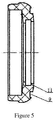
Figure 5 is a structural diagram of a waterproof ring seat of the invention. - Marks in the figures: 1-brake cylinder body; 2-front cover; 3-waterproof dust cover assembly; 4-brake cylinder dust cover; 5-filter felt support; 6- filter felt pad; 7-skirt; 8-boss; 9-ring slot; 10-filter cover of front cover; 11-waterproof ring seat; 12-piston rod; 13-double-lip waterproof ring; 14-O seal ring B; and 15-release spring.
- The invention will be described in detail in combination with accompanied drawings.
- In order to make the purpose, technical solution and advantages of the invention more clear, the invention will be described in detail in combination with accompanied drawings and embodiments. It should be understood that various embodiments described herein are only used to explain the invention rather than defining the invention.
- As shown in
Figure 2 andFigure 3 , a waterproof brake cylinder comprises a brake cylinder body 1 and afront cover 2. A waterproofdust cover assembly 3 is arranged on thefront cover 2. The waterproofdust cover assembly 3 comprises a brake cylinder dust cover 4 fixedly connected to thefront cover 2, and a filter felt support 5 and a filter feltpad 6 which are arranged in the brake cylinder dust cover 4. The filter felt support 5 is connected with the brake cylinder dust cover 4, and the filter feltpad 6 is fixed on the filter felt support 5. An outwards extending skirt 7 is arranged at the edge of the brake cylinder dust cover 4 in the axial direction thereof. The skirt 7 and the brake cylinder dust cover 4 are formed into an integrated structure. The skirt 7 takes the shape of a bell mouth as a whole. An outwards extending boss 8 is arranged at a vent of the brake cylinder dust cover 4 in the axial direction thereof, thus further preventing rain water from entering the dust cover. - As shown in
Figure 3 , when rain water flows down along the brake cylinder dust cover, rain water will fall down along the skirt directly because of the water retaining effect of the skirt on the brake cylinder dust cover so as to isolate the gas passage from the flowing path of rain water, which plays a waterproof role. When the brake cylinder is released, negative pressure is formed above the filter felt pad of a filter assembly. However, as rain water cannot reach the place C of the brake cylinder dust cover due to the block from the skirt, rain water will not be sucked into the cylinder. Even if a small part of the rain water flows to the place C, rain water will be stopped by the boss at the place C again, which ensures that rain water can not enter the brake cylinder dust cover. - As shown in
Figure 4 , awaterproof ring seat 11 for mounting thefilter cover 10 of front cover is arranged in thefront cover 2, and thewaterproof ring seat 11 is sleeved on thepiston rod 12 of the brake cylinder. A double-lipwaterproof ring 13 is arranged on thewaterproof ring seat 11 and between thewaterproof ring seat 11 and thepiston rod 12. The double-lip waterproof ring is made from high-hardness polyurethane, which reduces friction with the piston rod, and can prevent rain water from entering the cylinder body from the place A. AnO seal ring 14 is arranged on thewaterproof ring seat 11 and between thewaterproof ring seat 11 and thefront cover 2. As shown inFigure 5 , a ring slot 9 is arranged at the outer end surface of thewaterproof ring seat 11, and theO seal ring 14 is assembled in the ring slot 9. With the acting force of arelease spring 15, theO seal ring 14 deforms and plays a sealing role, which prevents rain water from entering the cylinder from the place B between the front cover and a dust ring mounting base. The filter cover of front cover is sealed through the O seal ring and the double-lip waterproof ring, which avoids direct contact with the atmosphere, reduces volatilization of 89M lubricating grease stored in the cover, slows oxidative deterioration down and is useful for lubrication and rust protection of the piston rod. - The invention makes structural improvement for the three water leakage positions A, B and C in
Figure 1 . The invention provides a seal structure to play a waterproof role, thus effectively preventing pollution and corrosion in the brake cylinder due to rain water, which greatly reduces the service life of the brake cylinder and ensures safe driving. - The above mentioned examples are preferred examples of the invention only and not used to limit the invention.
Claims (6)
- A brake cylinder dust cover, the brake cylinder dust cover (4) being fixedly connectable to a front cover (2) of the brake cylinder, an outwards extending skirt (7) being arranged at the edge of the brake cylinder dust cover (4) in the axial direction thereof, characterized in that an outwards extending boss (8) is arranged at a vent of the brake cylinder dust cover (4) in the axial direction thereof.
- The brake cylinder dust cover according to claim 1, characterized in that the skirt (7) takes the shape of a bell mouth as a whole.
- The brake cylinder dust cover according to claim 1 or 2, characterized in that the skirt (7) and the brake cylinder dust cover (4) are formed into an integrated structure.
- A waterproof brake cylinder comprising the brake cylinder dust cover according to claim 1, 2 or 3, comprising a brake cylinder body (1) and a front cover (2), characterized in that said waterproof dust cover assembly (3) is arranged on the front cover (2); the waterproof dust cover assembly (3) comprises a brake cylinder dust cover (4) fixedly connected to the front cover (2), and a filter felt support (5) and a filter felt pad (6) which are arranged in the brake cylinder dust cover (4); the filter felt support (5) is connected with the brake cylinder dust cover (4), and the filter felt pad (6) is fixed on the filter felt support (5); and an outwards extending skirt (7) is arranged at the edge of the brake cylinder dust cover (4) in the axial direction thereof.
- The waterproof brake cylinder according to claim 4, characterized in that a waterproof ring seat (11) for mounting a filter cover (10) of front cover is arranged in the front cover (2); the waterproof ring seat (11) is sleeved on a piston rod (12) of the brake cylinder; a double-lip waterproof ring (13) is arranged on the waterproof ring seat (11) and between the waterproof ring seat (11) and the piston rod (12); and an O seal ring (14) is arranged on the waterproof ring seat (11) and between the waterproof ring seat (11) and the front cover (2).
- The waterproof brake cylinder according to claim 5, characterized in that a ring slot (9) is arranged at the outer end face of the waterproof ring seat (11), and the O seal ring (14) is assembled in the ring slot (9).
Priority Applications (1)
| Application Number | Priority Date | Filing Date | Title |
|---|---|---|---|
| PL16840284T PL3254927T3 (en) | 2016-04-13 | 2016-09-29 | Dustproof cover for brake cylinder and waterproof brake cylinder using dustproof cover |
Applications Claiming Priority (3)
| Application Number | Priority Date | Filing Date | Title |
|---|---|---|---|
| CN201620304099.9U CN205479329U (en) | 2016-04-13 | 2016-04-13 | Can waterproof checking cylinder shield |
| CN201610587732.4A CN106080559B (en) | 2016-07-25 | 2016-07-25 | Waterproof brake cylinder |
| PCT/CN2016/100735 WO2017177627A1 (en) | 2016-04-13 | 2016-09-29 | Dustproof cover for brake cylinder and waterproof brake cylinder using dustproof cover |
Publications (3)
| Publication Number | Publication Date |
|---|---|
| EP3254927A1 EP3254927A1 (en) | 2017-12-13 |
| EP3254927A4 EP3254927A4 (en) | 2018-06-20 |
| EP3254927B1 true EP3254927B1 (en) | 2018-12-26 |
Family
ID=60042204
Family Applications (1)
| Application Number | Title | Priority Date | Filing Date |
|---|---|---|---|
| EP16840284.0A Active EP3254927B1 (en) | 2016-04-13 | 2016-09-29 | Dustproof cover for brake cylinder and waterproof brake cylinder using dustproof cover |
Country Status (7)
| Country | Link |
|---|---|
| US (1) | US10428885B2 (en) |
| EP (1) | EP3254927B1 (en) |
| AU (2) | AU2016291543A1 (en) |
| CA (1) | CA2968142C (en) |
| MX (1) | MX379388B (en) |
| PL (1) | PL3254927T3 (en) |
| WO (1) | WO2017177627A1 (en) |
Families Citing this family (3)
| Publication number | Priority date | Publication date | Assignee | Title |
|---|---|---|---|---|
| EP3797229B1 (en) * | 2018-05-22 | 2022-10-19 | MANN+HUMMEL GmbH | Brake dust particle filter and disc brake assembly comprising a brake dust particle filter |
| IT201900022086A1 (en) * | 2019-11-25 | 2021-05-25 | Faiveley Transport Italia Spa | Braking system for carrying out additional safe braking functions |
| US11866016B2 (en) | 2020-09-10 | 2024-01-09 | Industrial Machine Service, Inc. | Gas-liquid separating gas exchange device |
Family Cites Families (24)
| Publication number | Priority date | Publication date | Assignee | Title |
|---|---|---|---|---|
| US1615370A (en) * | 1926-04-05 | 1927-01-25 | Westinghouse Air Brake Co | Brake-cylinder device |
| BE497691A (en) * | 1950-01-28 | 1900-01-01 | ||
| US3183795A (en) * | 1962-12-24 | 1965-05-18 | Westinghouse Air Brake Co | Brake cylinder assembly |
| GB1128167A (en) * | 1965-07-30 | 1968-09-25 | Girling Ltd | Improvements in and relating to disc brakes |
| DE1525897A1 (en) * | 1966-09-24 | 1969-09-18 | Teves Gmbh Alfred | Closure of cylinder openings |
| US3447647A (en) * | 1967-09-05 | 1969-06-03 | Westinghouse Air Brake Co | Hydraulic-pneumatic tread brake unit for railway car trucks |
| DE2133953B2 (en) * | 1971-07-08 | 1973-09-27 | Westinghouse Bremsen- Und Apparatebau Gmbh, 3000 Hannover | Bellows for sealing the piston rod leadthrough of a cylinder, in particular a brake cylinder for pneumatic vehicle brakes |
| US3814483A (en) * | 1973-05-22 | 1974-06-04 | Westinghouse Air Brake Co | Blending valve device for combining fluid pressure and dynamic brakes |
| US4016318A (en) * | 1976-07-16 | 1977-04-05 | General Latex And Chemical Corporation | Automotive carpet mat and method of preparing same |
| US4058348A (en) * | 1977-03-04 | 1977-11-15 | Westinghouse Air Brake Company | Brake apparatus with a combined brake cylinder and reservoir |
| DE4127830A1 (en) * | 1991-08-22 | 1993-02-25 | Teves Gmbh Alfred | PROTECTIVE CAP FOR THE BRAKE CYLINDER OF A DISC BRAKE |
| DE19512997C1 (en) * | 1995-04-06 | 1996-11-07 | Knorr Bremse Systeme | Actuating device for braking devices of rail vehicles |
| JP2004345394A (en) * | 2003-05-20 | 2004-12-09 | Hino Motors Ltd | Master cylinder |
| CN2879484Y (en) * | 2005-12-07 | 2007-03-14 | 张辉 | Outdoor knife switch anti-rain cover for transformer substation |
| FR2928121B1 (en) * | 2008-03-03 | 2010-05-07 | Peugeot Citroen Automobiles Sa | AUTOMOTIVE MOTOR VEHICLE BRAKE PNEUMATIC AMPLIFIER WITH INTERCHANGEABLE FILTER, FILTER SUPPORT, AND INTERCHANGEABLE FILTER THEREFOR |
| US9676380B2 (en) * | 2008-09-18 | 2017-06-13 | Wabtec Holding Corp. | Universal venting arrangement for a railway vehicle brake cylinder |
| US8240642B2 (en) * | 2010-02-12 | 2012-08-14 | Bwi Company Limited S.A. | Fluid damper with internal compression spring |
| CN202790240U (en) * | 2012-08-10 | 2013-03-13 | 南车长江车辆有限公司 | Dust filtration device of railway vehicle brake cylinder |
| CN103352942A (en) * | 2013-07-19 | 2013-10-16 | 四川制动科技股份有限公司 | Railway wagon brake cylinder |
| CN203374709U (en) * | 2013-07-19 | 2014-01-01 | 四川制动科技股份有限公司 | Brake cylinder of wagon |
| KR101509974B1 (en) * | 2013-11-19 | 2015-04-07 | 현대자동차주식회사 | Waterproof device for drum brake |
| AT516143B1 (en) * | 2014-08-13 | 2021-02-15 | Siemens Mobility Austria Gmbh | Rail vehicle with air conditioning and a friction brake |
| CN205479329U (en) * | 2016-04-13 | 2016-08-17 | 眉山中车制动科技股份有限公司 | Can waterproof checking cylinder shield |
| CN205479043U (en) * | 2016-04-13 | 2016-08-17 | 眉山中车制动科技股份有限公司 | Can waterproof checking cylinder |
-
2016
- 2016-09-29 US US15/500,482 patent/US10428885B2/en active Active
- 2016-09-29 AU AU2016291543A patent/AU2016291543A1/en not_active Abandoned
- 2016-09-29 MX MX2017007472A patent/MX379388B/en unknown
- 2016-09-29 EP EP16840284.0A patent/EP3254927B1/en active Active
- 2016-09-29 PL PL16840284T patent/PL3254927T3/en unknown
- 2016-09-29 WO PCT/CN2016/100735 patent/WO2017177627A1/en not_active Ceased
- 2016-09-29 CA CA2968142A patent/CA2968142C/en active Active
-
2019
- 2019-01-25 AU AU2019200526A patent/AU2019200526B2/en active Active
Also Published As
| Publication number | Publication date |
|---|---|
| CA2968142C (en) | 2020-05-12 |
| AU2019200526A1 (en) | 2019-02-14 |
| CA2968142A1 (en) | 2017-10-13 |
| AU2019200526B2 (en) | 2021-02-25 |
| WO2017177627A1 (en) | 2017-10-19 |
| MX379388B (en) | 2025-03-11 |
| MX2017007472A (en) | 2018-03-23 |
| EP3254927A1 (en) | 2017-12-13 |
| US20180202503A1 (en) | 2018-07-19 |
| EP3254927A4 (en) | 2018-06-20 |
| PL3254927T3 (en) | 2019-05-31 |
| AU2016291543A1 (en) | 2017-11-02 |
| US10428885B2 (en) | 2019-10-01 |
Similar Documents
| Publication | Publication Date | Title |
|---|---|---|
| AU2019200526B2 (en) | Brake cylinder dust cover and waterproof brake cylinder using such dust cover | |
| CN105805373B (en) | A kind of breather valve, fuel tank cap and fuel tank | |
| CN211852931U (en) | Breather valve of oil tank | |
| JP2012036941A (en) | Gear device for electric motor | |
| CN205479043U (en) | Can waterproof checking cylinder | |
| CN201866354U (en) | Breather valve | |
| CN106080559B (en) | Waterproof brake cylinder | |
| CN202545913U (en) | Oil tank safety valve | |
| CN202100636U (en) | Internal respiration spring braking gas chamber | |
| CN100516497C (en) | Fuel tank cap of general gasoline engine | |
| CN205479329U (en) | Can waterproof checking cylinder shield | |
| CN201615159U (en) | Piston type brake sub-chamber | |
| CN202140544U (en) | Backflow type vent cap for deceleration or speed changing box used for vehicle | |
| CN205836797U (en) | A kind of waterproof checking cylinder | |
| JP2005280514A (en) | Suspension device | |
| CN105437924A (en) | Automobile air-conditioner air outlet shell with protective filtering device | |
| CN201891772U (en) | Wheel cylinder assembly | |
| CN211082583U (en) | Bearing with sealing structure | |
| CN201346961Y (en) | Rear axle ventilation plug for automobiles | |
| CN221482590U (en) | Ventilation plug assembly structure | |
| CN109854792B (en) | Two-way breather valve of unmanned aerial vehicle oil tank | |
| JP4306065B2 (en) | Float valve device and mounting structure of float valve device | |
| CN114658826A (en) | Ventilation mechanism, gearbox and car | |
| CN223076353U (en) | Dynamic sealing press cap for electromagnetic valve | |
| CN219806699U (en) | Anti-overflow oil dustproof fuel tank cap |
Legal Events
| Date | Code | Title | Description |
|---|---|---|---|
| STAA | Information on the status of an ep patent application or granted ep patent |
Free format text: STATUS: UNKNOWN |
|
| STAA | Information on the status of an ep patent application or granted ep patent |
Free format text: STATUS: THE INTERNATIONAL PUBLICATION HAS BEEN MADE |
|
| PUAI | Public reference made under article 153(3) epc to a published international application that has entered the european phase |
Free format text: ORIGINAL CODE: 0009012 |
|
| STAA | Information on the status of an ep patent application or granted ep patent |
Free format text: STATUS: REQUEST FOR EXAMINATION WAS MADE |
|
| 17P | Request for examination filed |
Effective date: 20170307 |
|
| AK | Designated contracting states |
Kind code of ref document: A1 Designated state(s): AL AT BE BG CH CY CZ DE DK EE ES FI FR GB GR HR HU IE IS IT LI LT LU LV MC MK MT NL NO PL PT RO RS SE SI SK SM TR |
|
| AX | Request for extension of the european patent |
Extension state: BA ME |
|
| RIN1 | Information on inventor provided before grant (corrected) |
Inventor name: WEI, XUELI Inventor name: ZHANG, JUNYING Inventor name: XIAO, CHEN Inventor name: DU, XIA Inventor name: QUAN, QIONG Inventor name: SHEN, JIANHONG Inventor name: LV, LIANG Inventor name: LV, CHAO Inventor name: LIU, YI Inventor name: WANG, QIN Inventor name: WANG, KAIEN Inventor name: XIAO, WEIYUAN Inventor name: LI, GUO Inventor name: MAO, FUYING Inventor name: AN, HONG Inventor name: SHI, YUNXIAO |
|
| A4 | Supplementary search report drawn up and despatched |
Effective date: 20180518 |
|
| RIC1 | Information provided on ipc code assigned before grant |
Ipc: B61H 11/00 20060101AFI20180514BHEP |
|
| GRAP | Despatch of communication of intention to grant a patent |
Free format text: ORIGINAL CODE: EPIDOSNIGR1 |
|
| STAA | Information on the status of an ep patent application or granted ep patent |
Free format text: STATUS: GRANT OF PATENT IS INTENDED |
|
| GRAS | Grant fee paid |
Free format text: ORIGINAL CODE: EPIDOSNIGR3 |
|
| DAX | Request for extension of the european patent (deleted) | ||
| INTG | Intention to grant announced |
Effective date: 20181023 |
|
| GRAA | (expected) grant |
Free format text: ORIGINAL CODE: 0009210 |
|
| STAA | Information on the status of an ep patent application or granted ep patent |
Free format text: STATUS: THE PATENT HAS BEEN GRANTED |
|
| AK | Designated contracting states |
Kind code of ref document: B1 Designated state(s): AL AT BE BG CH CY CZ DE DK EE ES FI FR GB GR HR HU IE IS IT LI LT LU LV MC MK MT NL NO PL PT RO RS SE SI SK SM TR |
|
| DAV | Request for validation of the european patent (deleted) | ||
| REG | Reference to a national code |
Ref country code: GB Ref legal event code: FG4D |
|
| REG | Reference to a national code |
Ref country code: CH Ref legal event code: EP |
|
| REG | Reference to a national code |
Ref country code: AT Ref legal event code: REF Ref document number: 1080999 Country of ref document: AT Kind code of ref document: T Effective date: 20190115 |
|
| REG | Reference to a national code |
Ref country code: DE Ref legal event code: R096 Ref document number: 602016008808 Country of ref document: DE |
|
| REG | Reference to a national code |
Ref country code: IE Ref legal event code: FG4D |
|
| REG | Reference to a national code |
Ref country code: SE Ref legal event code: TRGR |
|
| PG25 | Lapsed in a contracting state [announced via postgrant information from national office to epo] |
Ref country code: BG Free format text: LAPSE BECAUSE OF FAILURE TO SUBMIT A TRANSLATION OF THE DESCRIPTION OR TO PAY THE FEE WITHIN THE PRESCRIBED TIME-LIMIT Effective date: 20190326 Ref country code: NO Free format text: LAPSE BECAUSE OF FAILURE TO SUBMIT A TRANSLATION OF THE DESCRIPTION OR TO PAY THE FEE WITHIN THE PRESCRIBED TIME-LIMIT Effective date: 20190326 Ref country code: LT Free format text: LAPSE BECAUSE OF FAILURE TO SUBMIT A TRANSLATION OF THE DESCRIPTION OR TO PAY THE FEE WITHIN THE PRESCRIBED TIME-LIMIT Effective date: 20181226 Ref country code: LV Free format text: LAPSE BECAUSE OF FAILURE TO SUBMIT A TRANSLATION OF THE DESCRIPTION OR TO PAY THE FEE WITHIN THE PRESCRIBED TIME-LIMIT Effective date: 20181226 Ref country code: HR Free format text: LAPSE BECAUSE OF FAILURE TO SUBMIT A TRANSLATION OF THE DESCRIPTION OR TO PAY THE FEE WITHIN THE PRESCRIBED TIME-LIMIT Effective date: 20181226 Ref country code: FI Free format text: LAPSE BECAUSE OF FAILURE TO SUBMIT A TRANSLATION OF THE DESCRIPTION OR TO PAY THE FEE WITHIN THE PRESCRIBED TIME-LIMIT Effective date: 20181226 |
|
| REG | Reference to a national code |
Ref country code: NL Ref legal event code: MP Effective date: 20181226 |
|
| REG | Reference to a national code |
Ref country code: LT Ref legal event code: MG4D |
|
| PG25 | Lapsed in a contracting state [announced via postgrant information from national office to epo] |
Ref country code: AL Free format text: LAPSE BECAUSE OF FAILURE TO SUBMIT A TRANSLATION OF THE DESCRIPTION OR TO PAY THE FEE WITHIN THE PRESCRIBED TIME-LIMIT Effective date: 20181226 Ref country code: RS Free format text: LAPSE BECAUSE OF FAILURE TO SUBMIT A TRANSLATION OF THE DESCRIPTION OR TO PAY THE FEE WITHIN THE PRESCRIBED TIME-LIMIT Effective date: 20181226 Ref country code: GR Free format text: LAPSE BECAUSE OF FAILURE TO SUBMIT A TRANSLATION OF THE DESCRIPTION OR TO PAY THE FEE WITHIN THE PRESCRIBED TIME-LIMIT Effective date: 20190327 |
|
| REG | Reference to a national code |
Ref country code: AT Ref legal event code: MK05 Ref document number: 1080999 Country of ref document: AT Kind code of ref document: T Effective date: 20181226 |
|
| PG25 | Lapsed in a contracting state [announced via postgrant information from national office to epo] |
Ref country code: NL Free format text: LAPSE BECAUSE OF FAILURE TO SUBMIT A TRANSLATION OF THE DESCRIPTION OR TO PAY THE FEE WITHIN THE PRESCRIBED TIME-LIMIT Effective date: 20181226 |
|
| PG25 | Lapsed in a contracting state [announced via postgrant information from national office to epo] |
Ref country code: PT Free format text: LAPSE BECAUSE OF FAILURE TO SUBMIT A TRANSLATION OF THE DESCRIPTION OR TO PAY THE FEE WITHIN THE PRESCRIBED TIME-LIMIT Effective date: 20190426 Ref country code: IT Free format text: LAPSE BECAUSE OF FAILURE TO SUBMIT A TRANSLATION OF THE DESCRIPTION OR TO PAY THE FEE WITHIN THE PRESCRIBED TIME-LIMIT Effective date: 20181226 Ref country code: ES Free format text: LAPSE BECAUSE OF FAILURE TO SUBMIT A TRANSLATION OF THE DESCRIPTION OR TO PAY THE FEE WITHIN THE PRESCRIBED TIME-LIMIT Effective date: 20181226 Ref country code: CZ Free format text: LAPSE BECAUSE OF FAILURE TO SUBMIT A TRANSLATION OF THE DESCRIPTION OR TO PAY THE FEE WITHIN THE PRESCRIBED TIME-LIMIT Effective date: 20181226 |
|
| PG25 | Lapsed in a contracting state [announced via postgrant information from national office to epo] |
Ref country code: EE Free format text: LAPSE BECAUSE OF FAILURE TO SUBMIT A TRANSLATION OF THE DESCRIPTION OR TO PAY THE FEE WITHIN THE PRESCRIBED TIME-LIMIT Effective date: 20181226 Ref country code: SM Free format text: LAPSE BECAUSE OF FAILURE TO SUBMIT A TRANSLATION OF THE DESCRIPTION OR TO PAY THE FEE WITHIN THE PRESCRIBED TIME-LIMIT Effective date: 20181226 Ref country code: IS Free format text: LAPSE BECAUSE OF FAILURE TO SUBMIT A TRANSLATION OF THE DESCRIPTION OR TO PAY THE FEE WITHIN THE PRESCRIBED TIME-LIMIT Effective date: 20190426 Ref country code: RO Free format text: LAPSE BECAUSE OF FAILURE TO SUBMIT A TRANSLATION OF THE DESCRIPTION OR TO PAY THE FEE WITHIN THE PRESCRIBED TIME-LIMIT Effective date: 20181226 Ref country code: SK Free format text: LAPSE BECAUSE OF FAILURE TO SUBMIT A TRANSLATION OF THE DESCRIPTION OR TO PAY THE FEE WITHIN THE PRESCRIBED TIME-LIMIT Effective date: 20181226 |
|
| REG | Reference to a national code |
Ref country code: DE Ref legal event code: R097 Ref document number: 602016008808 Country of ref document: DE |
|
| PG25 | Lapsed in a contracting state [announced via postgrant information from national office to epo] |
Ref country code: DK Free format text: LAPSE BECAUSE OF FAILURE TO SUBMIT A TRANSLATION OF THE DESCRIPTION OR TO PAY THE FEE WITHIN THE PRESCRIBED TIME-LIMIT Effective date: 20181226 Ref country code: AT Free format text: LAPSE BECAUSE OF FAILURE TO SUBMIT A TRANSLATION OF THE DESCRIPTION OR TO PAY THE FEE WITHIN THE PRESCRIBED TIME-LIMIT Effective date: 20181226 |
|
| PLBE | No opposition filed within time limit |
Free format text: ORIGINAL CODE: 0009261 |
|
| STAA | Information on the status of an ep patent application or granted ep patent |
Free format text: STATUS: NO OPPOSITION FILED WITHIN TIME LIMIT |
|
| 26N | No opposition filed |
Effective date: 20190927 |
|
| PG25 | Lapsed in a contracting state [announced via postgrant information from national office to epo] |
Ref country code: SI Free format text: LAPSE BECAUSE OF FAILURE TO SUBMIT A TRANSLATION OF THE DESCRIPTION OR TO PAY THE FEE WITHIN THE PRESCRIBED TIME-LIMIT Effective date: 20181226 |
|
| PG25 | Lapsed in a contracting state [announced via postgrant information from national office to epo] |
Ref country code: TR Free format text: LAPSE BECAUSE OF FAILURE TO SUBMIT A TRANSLATION OF THE DESCRIPTION OR TO PAY THE FEE WITHIN THE PRESCRIBED TIME-LIMIT Effective date: 20181226 |
|
| PG25 | Lapsed in a contracting state [announced via postgrant information from national office to epo] |
Ref country code: MC Free format text: LAPSE BECAUSE OF FAILURE TO SUBMIT A TRANSLATION OF THE DESCRIPTION OR TO PAY THE FEE WITHIN THE PRESCRIBED TIME-LIMIT Effective date: 20181226 |
|
| REG | Reference to a national code |
Ref country code: CH Ref legal event code: PL |
|
| PG25 | Lapsed in a contracting state [announced via postgrant information from national office to epo] |
Ref country code: IE Free format text: LAPSE BECAUSE OF NON-PAYMENT OF DUE FEES Effective date: 20190929 Ref country code: LU Free format text: LAPSE BECAUSE OF NON-PAYMENT OF DUE FEES Effective date: 20190929 Ref country code: CH Free format text: LAPSE BECAUSE OF NON-PAYMENT OF DUE FEES Effective date: 20190930 Ref country code: LI Free format text: LAPSE BECAUSE OF NON-PAYMENT OF DUE FEES Effective date: 20190930 |
|
| REG | Reference to a national code |
Ref country code: BE Ref legal event code: MM Effective date: 20190930 |
|
| PG25 | Lapsed in a contracting state [announced via postgrant information from national office to epo] |
Ref country code: BE Free format text: LAPSE BECAUSE OF NON-PAYMENT OF DUE FEES Effective date: 20190930 |
|
| PG25 | Lapsed in a contracting state [announced via postgrant information from national office to epo] |
Ref country code: FR Free format text: LAPSE BECAUSE OF NON-PAYMENT OF DUE FEES Effective date: 20190930 |
|
| GBPC | Gb: european patent ceased through non-payment of renewal fee |
Effective date: 20200929 |
|
| PG25 | Lapsed in a contracting state [announced via postgrant information from national office to epo] |
Ref country code: CY Free format text: LAPSE BECAUSE OF FAILURE TO SUBMIT A TRANSLATION OF THE DESCRIPTION OR TO PAY THE FEE WITHIN THE PRESCRIBED TIME-LIMIT Effective date: 20181226 |
|
| PG25 | Lapsed in a contracting state [announced via postgrant information from national office to epo] |
Ref country code: HU Free format text: LAPSE BECAUSE OF FAILURE TO SUBMIT A TRANSLATION OF THE DESCRIPTION OR TO PAY THE FEE WITHIN THE PRESCRIBED TIME-LIMIT; INVALID AB INITIO Effective date: 20160929 Ref country code: MT Free format text: LAPSE BECAUSE OF FAILURE TO SUBMIT A TRANSLATION OF THE DESCRIPTION OR TO PAY THE FEE WITHIN THE PRESCRIBED TIME-LIMIT Effective date: 20181226 |
|
| PG25 | Lapsed in a contracting state [announced via postgrant information from national office to epo] |
Ref country code: GB Free format text: LAPSE BECAUSE OF NON-PAYMENT OF DUE FEES Effective date: 20200929 |
|
| PG25 | Lapsed in a contracting state [announced via postgrant information from national office to epo] |
Ref country code: MK Free format text: LAPSE BECAUSE OF FAILURE TO SUBMIT A TRANSLATION OF THE DESCRIPTION OR TO PAY THE FEE WITHIN THE PRESCRIBED TIME-LIMIT Effective date: 20181226 |
|
| PGFP | Annual fee paid to national office [announced via postgrant information from national office to epo] |
Ref country code: DE Payment date: 20250926 Year of fee payment: 10 |
|
| PGFP | Annual fee paid to national office [announced via postgrant information from national office to epo] |
Ref country code: PL Payment date: 20250826 Year of fee payment: 10 |
|
| PGFP | Annual fee paid to national office [announced via postgrant information from national office to epo] |
Ref country code: SE Payment date: 20250930 Year of fee payment: 10 |